coiled tubing center stages
TRANSCRIPT
8/6/2019 Coiled Tubing Center Stages
http://slidepdf.com/reader/full/coiled-tubing-center-stages 1/15
Coiled Tubing Takes Center Stage
David BigioAndy RikeA nchorage, A laska, U SA
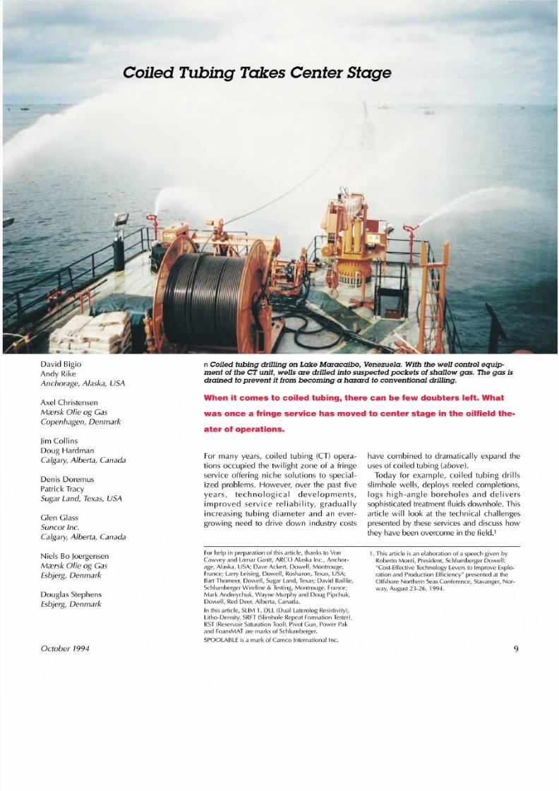
n Coiled tubing drilling on Lake Maracaibo, Venezuela. With the well control equip-ment of the CT unit, wells are drilled into suspected pockets of shallow gas. The gas isdrained to prevent it from becoming a hazard to conventional drilling.
Axel ChristensenMC€r sk O l ieog CasC op en ha gen , D enma rk
When it comes to coiled tubing, there can be few doubters left. What
was once a fringe service has moved to center stage in the oilfield the-
ater of operations.
JimCollinsDoug HardmanCa lg ar y, A lb er ta , C a na da
For many years, coiled tubing (CT) opera-tions occupied the twilight zone of a fringeservice offering niche solutions to special-
ized problems. However, over the past fiveyears, technological developments,improved service reliability, graduallyincreasing tubing diameter and an ever-growing need to drive down industry costs
Denis Doremus
Patrick TracySugar Land, Texas, U SA
Glen GlassS un co r In c.C a lg ar y, A lb er ta , C a na da
have combined to dramatically expand theusesof coiled tubing (above).Today for example, coiled tubing drills
slimhole wells, deploys reeled completions,logs high-angle boreholes and deliverssophisticated treatment fluids downhole. Thisarticle will look at the technical challengespresented by these services and discuss howthey have been overcome in the field.'
Niels Bo JoergensenMC€r sk O l ieog CasEsbj erg, Denma rk
F or h elp in p re pa ra tio n o f th is a rtic le , th ank s to VonC aw ve y a nd L am ar G antt, A RC O A la sk a Inc ., A nc ho r-a ge , A la sk a, U SA ; D av e A ck ert, D ow ell, M on tro ug e,F ra nc e; L arry L eis in g, D ow ell, R os ha ro n, Tex as , U SA ;B art T ho me er, D ow ell, S ug ar L an d, Tex as ; D av id B aillie ,S c hl umbe rg e r Wi re li ne & Tes ti ng , M o ntr ou ge , F ra nc e;M ark A ndreychuk, Wayne M urphy and D oug P ipchuk,D ow ell, R ed D ee r, A lb erta , C an ad a.
In th is a rtic le , S LIM 1 , D LL (D ua l L ate ro lo g R es is tiv ity ),L ith o- De ns ity , S R FT ( Slim h ol e R e pe at F orma tio n Te st er ),R ST (R es erv oir S atu ra tio n Too l), P iv ot G un , P ow er P aka nd F oa mMAT a re m ark s o f S ch lu mb erg er.
S PO OL AB LE is a m ark o f C am eo Inte rna tio na l Inc .
Douglas StephensEsbj erg, Denma rk
O ctober 1994
1 . T his a rtic le is a n e la bo ra tio n o f a s pe ec h g iv en b yR ob erto M on ti, P re sid en t, S ch lu mb erg er D ow ell:
" Co st-E ffe ctiv e Tec hn olo gy L ev ers to Im pro ve E xp lo -ra tio n a nd P ro du ctio n E ffic ie nc y" p re se nte d a t th eO ffs ho re N orth ern S ea s C o nfe re nc e, S ta va ng er, N or-
w ay , A ug ust 2 3-2 6, 1 99 4.
9
8/6/2019 Coiled Tubing Center Stages
http://slidepdf.com/reader/full/coiled-tubing-center-stages 2/15
Drilling Slimhole WellsSlimhole wells-generally those with a finaldiameter of 5 inches or less-have thepotential to deliver cost-effective solutionsto many financial and environmental prob-lems, cutting the amount of consumablesneeded to complete a well and producinglesswaste.2 Other benefits depend on what
kind of rig drills the well. Compared to con-ventional rigs, purpose-designed smallerrotary rigs can deliver slimhole wells usingfewer people on a much smaller drillsite,which cuts the cost of site preparation andsignificantly reduces the environmentalimpact of onshore drilling.'Coiled tubing drilling combines the virtues
of a small rig with some unique operationaladvantages, including the capability to runthe slim coiled tubing drillstring throughexisting completions to drill new sectionsbelow. There is also the opportunity to har-
nessa coiled tubing unit 's built-in well con-trol equipment to improve safety whendrilling potential high-pressure gas zones.This allows safe underbalanced drilling-when the well may flow during drilling.'Although there were attempts at CT
drilling in the mid-1970s, technologicaladvances were needed to make it viable.These include the development of largerdiameter, high-strength, reliable tubing, andthe introduction of smaller diameter positivedisplacement downhole motors, orientingtools, surveying systemsand fixed cutter bits.Furthermore, currently available coiled tub-ing engineering software enables importantparameters to be predicted, such as lockup-when tubing buckl i ng halts dri II i ngprogress-available weight on bit, expectedpump pressure, wellbore hydraulics andwellbore cleaning capabilitv>It was not until 1991 that the first positive
results of CT drilling were seen with thedeepening of a vertical well in France bySchlumberger Dowell and Elf Aquitaine,and the drilling of two horizontal reentry
wells in West Texas, operated by OryxEnergy CO.6Today, experience has beenbuilt up, technology development continuesand the number of wells drilled worldwideis set to increase rapidly (above, right)J
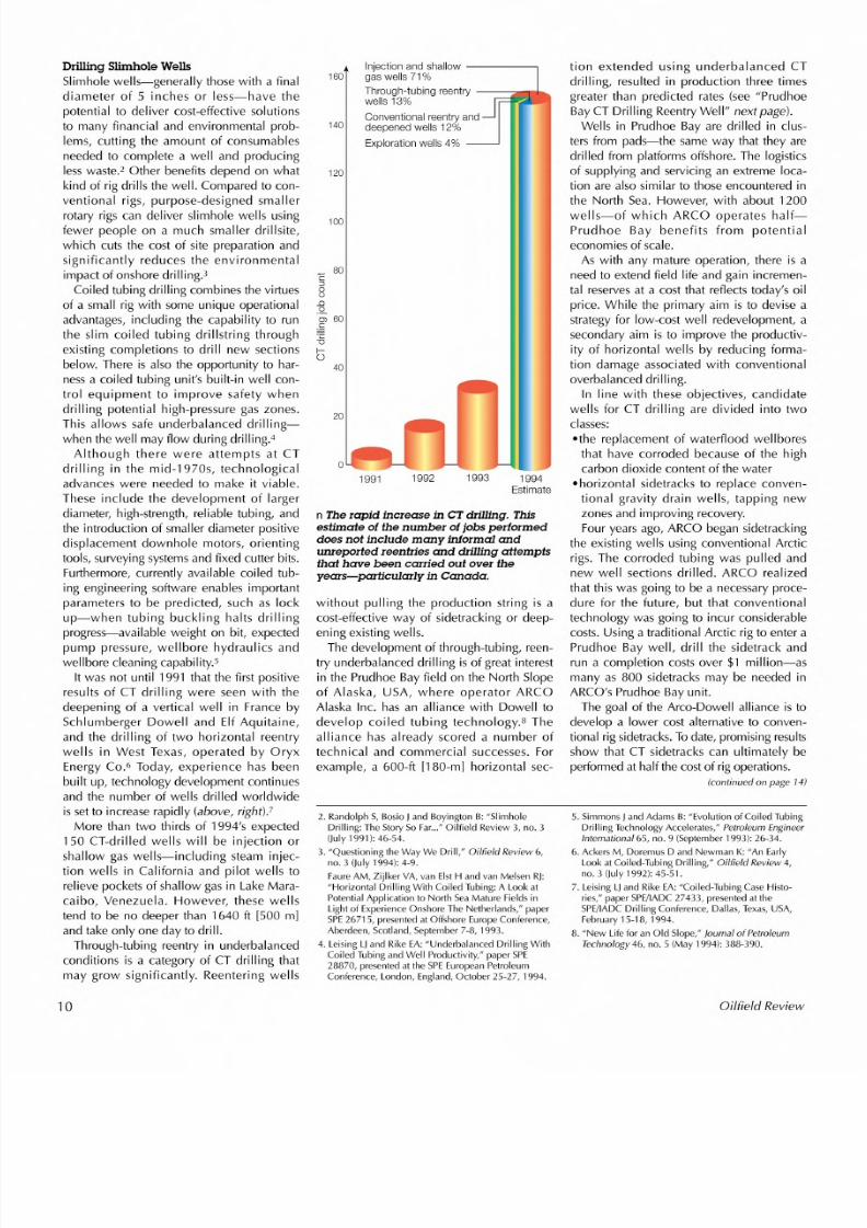
More than two thirds of 1994's expected150 CT-drilled wells will be injection orshallow gas wells-including steam injec-tion wells in California and pilot wells torelieve pockets of shallow gas in LakeMara-caibo, Venezuela. However, these wellstend to be no deeper than 1640 ft [500 m]and take only one day to drill .
Through-tubing reentry in underbalancedconditions is a category of CT drilling thatmay grow significantly. Reenter ing wells
10
I nj ec ti on a nd s ha ll ow - -- -- -- ,160 gas w ells 71 %
Through -tub ing reen try ----z-.,-r ....wells 1 3%
Conv en ti on al re en tr y a ndd eep en ed w ells 1 2%40
Expl or at io n we lls 4%
120
100
C 80::Joo_Q
o~ 60c-c:""0
b40
1991 1992 1993 1994Estimate
n The rapid increase in CT dril ling. Thisestimate of the number ofjobs performeddoes not include many informal andunreported reentries and drilling attempts
that have been carried out over theyears-particularly in Canada.
without pulling the production string is acost-effective way of sidetracking or deep-ening existing wells.The development of through-tubing, reen-
try underbalanced drilling isof great interestin the Prudhoe Bay field on the North Slopeof Alaska, USA, where operator ARCOAlaska Inc. has an alliance with Dowell todevelop coiled tubing technology.s Thealliance has already scored a number of
technical and commercial successes. Forexample, a 600-ft [180-ml horizontal sec-
tion extended using underbalanced CTdrilling, resulted in production three timesgreater than predicted rates (see "PrudhoeBay CT Drilling ReentryWell" next page).
Wells in Prudhoe Bay are drilled in clus-ters from pads-the same way that they aredrilled from platforms offshore. The logisticsof supplying and servicing an extreme loca-
tion are also similar to those encountered inthe North Sea. However, with about 1200wells-of which ARCO operates half-Prudhoe Bay benefits from potentialeconomies of scale.As with any mature operation, there is a
need to extend field life and gain incremen-tal reservesat a cost that reflects today's oilprice. While the primary aim is to devise astrategy for low-cost well redevelopment, asecondary aim is to improve the productiv-ity of horizontal wells by reducing forma-tion damage associated with conventional
overbalanced drilling.In line with these objectives, candidate
wells for CT drilling are divided into twoclasses:.the replacement of waterflood wellboresthat have corroded because of the highcarbon dioxide content of the water
• horizontal sidetracks to replace conven-tional gravity drain wells, tapping newzones and improving recovery.Four years ago, ARCO began sidetracking
the existing wells using conventional Arcticrigs. The corroded tubing was pulled andnew well sections drilled. ARCO realizedthat this was going to be a necessary proce-dure for the future, but that conventionaltechnology was going to incur considerablecosts. Using a traditional Arctic rig to enter aPrudhoe Bay well, drill the sidetrack andrun a completion costs over $1 million-asmany as 800 sidetracks may be needed inARCO's Prudhoe Bay unit.The goal of the Arco-Dowell alliance isto
develop a lower cost alternative to conven-tional rig sidetracks.Todate, promising results
show that CT sidetracks can ultimately beperformed at half the costof rig operations.(continued on page 14)
2 . R and olp h S , B osio J a nd B oy ingto n B : "S lim ho leD rillin g: T he S to ry S o F ar...n O ilfield Review 3, no. 3
(J uly 1 99 1): 4 6- 54 .
3 . "Q ue stio ning th e Way We D rill,"Oilfield R ev iew 6 ,no . 3 (Ju ly 1 99 4): 4 -9 _
Faure AM , Zijlker VA, van Elst H and van M elsen RJ:"H orizontal D rilling W ith Coiled Tubing: A Look atP ote ntia l A pp lica tio n to N orth S ea M atu re F ie ld s inL ig ht o f E xp erie nc e O ns ho re T he N eth erla nd s," p ap erS PE 2 67 15 , p re se nte d a t O ffs ho re E uro pe C onfe re nc e,A be rd ee n, S co tla nd , S ep tem be r 7 -8 ,1 99 3.
4 . L eising L J and R ike E A: "U nd erb alanc ed D rilling W ithC oile d T ub ing a nd Well P ro du ctiv ity ," p ape r S PE
2 88 70 , p re se nte d a t th e S PE E uro pe an P etro le umC on fe re nc e, L ond on , E ng la nd , O cto be r 2 5-2 7, 1 99 4.
5 . S im mo ns J a nd A da ms B : " Ev olu tion of C oile d T ub ingD ri ll in g Te chno lo g y Ac ce le ra te s ," P e tr ol eum Engi ne e rInternational 6 5, no. 9 (S ep te mb er 19 93 ): 2 6-3 4.
6. Ackers M, Doremus D and Newman K: "An EarlyL oo k a t C oile d-Tub in g D rillin g,"Oilfield R eview 4 ,n o. 3 (J uly 1 99 2): 4 5-5 1.
7 . L eis in g L J an d R ik e E A: " Co ile d-T ub in g C as e H is to -rie s," p ap er S PE /IA DC 2 74 33 , p re se nte d a t th eS PE /IA DC D rilling C on fe re nc e, D alla s, Tex as , U SA ,F eb ru ary 1 5-1 8, 1 99 4_
8. "New Life for an O ld Slope,"Journal of Petroleum
Technology 46 , no . 5 (M ay 1 99 4): 3 88 -3 90.
Oilfie ld Review
8/6/2019 Coiled Tubing Center Stages
http://slidepdf.com/reader/full/coiled-tubing-center-stages 3/15
Prudhoe Bay CT Drilling Reentry Well
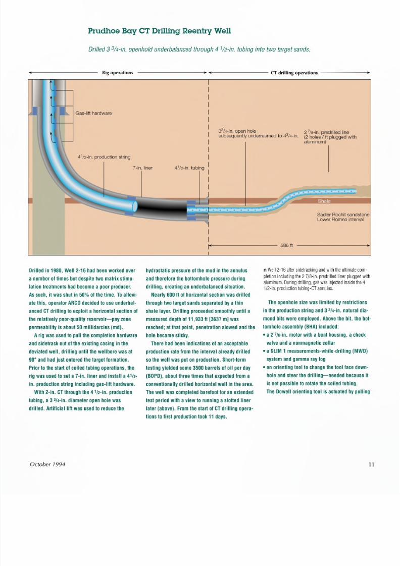
Dri l led3 3 /4 -in . o p en h old u n de rb a la n ce d th ro u gh4 1 /2 -in . tu bin g in to tw o ta rg et s an ds .
Rig operations --------- -------- CT drilling operations ------ ..
41/2 -in . p ro du ctio n s trin g
33 /4 -in . o pe n h ole 2 l is -in . p re dr il le d lin es ub se qu en tly u nd er re am ed to43 /4-in. (2 holes I ft p lu gg ed w ith
aluminum)
7 - i n. l in e r 4112 -i n. t ub ing
S ad le r Roc hit s an ds to neL ow er R om eo in te rv al
--------- 586 ft
Drille d in 1980, Well 2 -16 had beenworked ove r hyd ro sta tic p re ssu re o f t he mud in th e annu lu s
a number 01times but d esp ite two matrix stimu- and th ere lo re th e bottomho le p re ssu re during
la tion tr ea tmen ts had become a poor p roduce r. d rilling, c reating an underba lanced s ituation.
Assuch , it was shu t in 50% 01the time. Toa llevi-
a te this, operator ARCOdecided to use underbal-
anced CTdri ll ing to exploit a hor izonta l section 01
the relat ively poor-qual ity reservoir-pay zone
permeabil ity is about 50 mil lidarc ies (md).
A rig was used to pull the comple tion hardware
and sidetrack out 01the exist ing casing in the
dev ia ted well, d rilling until the well bore was a t
90° and had just entered the target lormation.
Prior to the s tart of coi led tubing operations, the
rig was u sed t o se t a 7 -in. line r a nd insta ll a41/2 -
in. production string including gas-lill hardware.
With 2-in. CTthrough the4 1/2-in. production
tubing, a 3 3 /4 -in .d i amete r open hole was
drilled. Artific ia llill was used to reduce the
October 1994
Nearly 600 II 01horizontal section was drilled
through two target sands separated by a thin
shale layer. Dri ll ing proceeded smoothly unt il a
measured depth 0111,93311 [3637 mJwas
reached; a t that paint , penetra tion slowed and the
hole became sticky.
There had been indications 01an acceptable
product ion rate from the interval a lready dri lled
so the wel l was put on product ion. Short -term
tes ting yie lded some 3500 barre ls 01oil per day
(BOPD),about three t imes that expected from a
convent ionally dri lled hor izonta l wel l in the area.
The wel l was completed bareloot for an extended
te st per iod with a v iew to running a s lo tted liner
later (above) . From the start 01CTdri ll ing opera-
t ions to f irst product ion took 11 days.
n We ll 2 -1 6 a fte r s id etra ck in g a nd w ith th e u lt im a te c om
p le tio n in clu d in g th e 2l I B - i n p re d rille d lin e r p lu g ge d w it ha lu m in um . D u rin g d rillin g, g as w a s in je cte d in sid e th e 4
1 /2 -in . p ro du c tio n tu b in g-C T a n nu lu s .
The openhole s ize was l imited by res tr ic tions
in the product ion str ing and 3 3/4-in. natural dia-
mond b its were employed. Above the b it, the bot-
tomhole assembly (BHA) included:
• a 2 7 /a -in. moto r with a b ent housing , a ch eck
valve and a nonmagnetic collar
• a SLIM 1 measurements-while-dr il ling (MWD)
sys tem and gamma ray log
• an orienting tool to change the tool lace down-
hole and s teer the d rilling-needed because it
i s not possible to rotate the coi led tubing.
The Dowel l orienting tool is actuated by pul ling
11
8/6/2019 Coiled Tubing Center Stages
http://slidepdf.com/reader/full/coiled-tubing-center-stages 4/15
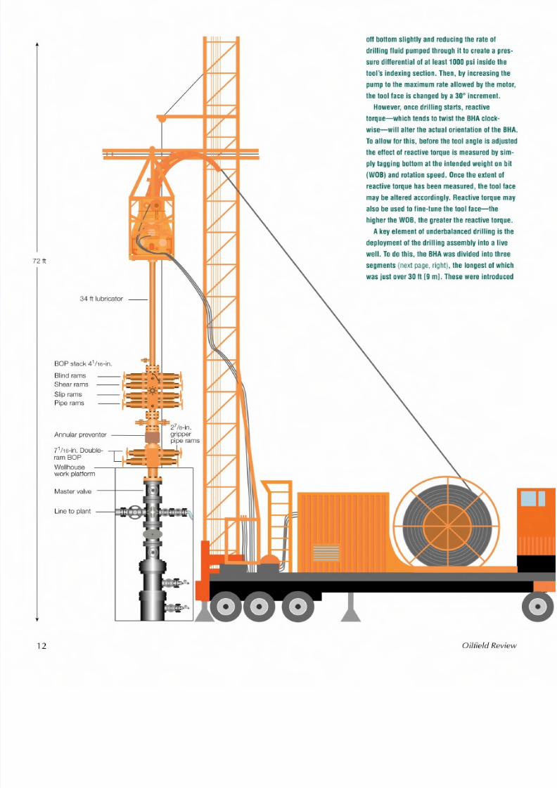
72 ft
BOP stack 41116-in.
B lin d r am s
S he ar r am s
S lip r am s
P ip e rams
71116-in. Double-ram BO P
Wellhousework p la tf orm
Ma st er v alv e
L in e to p la nt
12
34 ft lubricator --
off bol lom s lighlly and reduc ing the rate 01
drill ing lIu id pumped th rough it to c reate a p res-
sure different ia l 01at least1000psi ins ide the
tool' s indexing section. Then, by increas ing the
pump to the max imum rate a llowed by the moto r,
th e tool la ce is ch anged bya30 ° increment.
However, once drilling starts, reactive
to rque -wh ich tends to twis t the BHAclock-wise-will a lte r the actual o rienta tion 01the BHA.
Toa llow lo r th is , belo re the tool ang le is adjusted
the ellect 01react ive torque is measured by sim-
p ly tagg ing bol lom a t the in tended weight on b it
(WOB)and rotat ion speed. Oncethe extent 01
react ive torque hasbeen measured, the tool lace
may be altered accordingly. React ive torque may
also be used to l ine- tune the tool lace- the
higher the WOB,the greater the react ive torque.
A key element 01underbalanced dri ll ing is the
deployment 01the dri ll ing assembly into a l ivewell. Todo this , the BHAwas d iv ided into th ree
segments (next page,right), the longest 01which
was just ove r30 It [9 ml, These were int roduced
Oilfie ld Review
8/6/2019 Coiled Tubing Center Stages
http://slidepdf.com/reader/full/coiled-tubing-center-stages 5/15
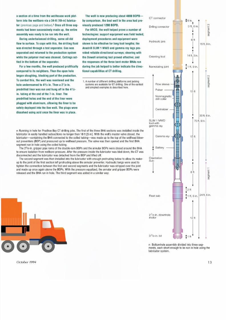
a s ec tio n a t a tim e fro m th e w e llh ou se w o rk p la t-
fo rm in to th e w e llb o re v ia a 3 4 -ft [1 0 -m ] lu b ric a-
to r (p re vio u s p ag e a nd b e lo w ). 'O n c ea ll th re es e g -
m e n ts h ad b ee n s uc ce ss iv e ly m a d e u p , th e e n tire
a ss em b ly w a s re ad y to b e ru n in to th e w e ll .
D u rin g u n de rb a la n ce d d rill in g , s o m e o il d id
flo w to s u rfa c e. To c o pe w i th th is , th e d ril lin g f lu id
w a s d ire c te d th ro u gh a te s t s ep a ra to r. G a s w a ss ep a ra te d a n d re tu rn e d to th e p ro d uc tio n s ys te m
w h ile th e p o ly m er m u d w a s c le an ed . C u tt in gs s e t-
lie d in th e b o tto m o f th e s e pa ra to r.
F o r a fe w m o n th s , th e w e ll p ro d uc ed p ro lific a lly
T he w e ll is n ow p ro du cin g a bo ut 4 00 0 B O P D-
b y c o m pa ris on , th e b es t w e ll in th e a re a h ad p re -
v io us ly p ro du ce d 1 20 0 B O P D .
F or A R C O , th e w e ll h e lp ed p ro ve a n um b er o f
te c h n olo g ie s : s u p p or t e q u ip m e n t w a s f ie ld te s te d ;
d e plo y m e nt p ro c ed u re s a n d e q uip m e n t w e re
s ho w n to b e e ffe ct iv e fo r lo ngto o l le n g th s ;th e
A na dr il l S LIM 1 M W D an d g am m a ra y lo gs p ro -v id e d r elia b le d ir ec tio n a l s u rv e y s; s te e rin g w i th
th e D o w e ll o rie n tin g to o l p ro v ed e ffe c tiv e ; a n d
th e re sp on se s o f t he th re e b en t-m o to r B H A s ru n
d u rin g th e jo b h e lp e d to b e tte r in d ic a te th e d ire c-
c om p are d to its n eig hb ors . T he n th e o pe n h ole tio na l c ap ab ili t ie s o f C T d rill in g .
b e g a n s lo u g h in g , b lo c k in g p a rt o f t he p ro d u c tio n .
T oc om b a t th is ,th e w e ll w a s re en te re d a nd th e
h o le u n de rre am e d to43/4 in . T h en a 2 7/s -in .
p re dr ille d lin er w a s ru n a nd h un g o ff in th e 4 1/2 -
i n . t u b in ga t th ee nd o f t he 7 -in . l in e r . T he
p re dr ille d h o le s a nd th e e nd o f t he lin e r w e rep lu gg ed w ith a lu m in um , a llo w in g th e lin er to b e
s afe ly d ep lo ye d in to th e liv e w e ll . T he p lu gs w e re
d is so lv ed u s in g a cid o nc e th e lin er w a s in p la ce .
1. A number o f d if fe rent d ri ll ing p la tf orms and j ackingsystems are avai lable forC Tdr il ling . Oneof the earl ies tand s imp le st examples i s descr ibed her e.
n R un nin g in h ole fo r P ru dh oe B ayC Td ri llin g jo b s . T h e fir s t o f th e th re e B H A s ec tio n s w a s in s ta lle d in s id e th elu br ic ato r in e as ily h an d le d s ub se ct io ns n o lo ng er th an 1 8 ft [5 m ] . W i th th e w e ll 's m a s te r v a lv e c lo se d , th e
lu br ic a to r- c o nta in in g th e B HA c o nn ec te d to th e c o ile d tu bin g-w a s m a de u p to th e to p o f th e w e llh ea d b lo w -o u t p re ve n te rs (B O P) a nd p re ss ur e d u p to w e llh ea d p re ss u re . T he va lv e w a s th en o pe ne d a nd th e fir s t B HAs eg m e n t ru n in h o le u sin g th e c o ile d tu b in g .
T he 2 7/s - in . g rip pe r p ip e ra m s o f th e d ou ble -r am B OP s a nd th e a nn ula r B OP s w e r e c lo se d a ro un d th e B HAto e ns ure is ola tio n fro m w e llb or e p re ss u re . A fte r th e p re ss ur e in sid e th e lu br ic a to r w a s b le d d ow n , th e C T w a sd is co nn ec te d a nd th e lu br ic ato r w a s d e ta ch ed fr o m th e B OP a nd lif te d o ff .T he s ec on d s eg m e n t w a s th en in s ta lle d in to th e lu br ic ato r w ith e no ug h p ro tr u d in g b e lo w to a llo w its m a k e -
u p to th e jo in t o f th e fir s t s ec tio n le ft p ro tr u d in g a bo ve th e a nn u la r p re ve n te r. H yd ra u lic to ng s w e re u se d tot ig h te n th e c on ne ct io n b e tw e en th e fir s t a nd s ec on d s eg m e n ts a nd th e lu br ic a to r w a s s tr ip pe d o ve r th e jo in ta nd m a d e u p o nc e a ga in a bo ve th e B OP s . W i th th e p re ss ur e e qu a liz e d , th e a nn u la r a nd g rip pe r B OP s w e re
r e le as e d a nd th e B HA ru n in h ole . T he th ird s e gm e nt w a s a dd ed in a s im i la r w a y .
October 1994
CT connector
Drilling connector
Hydrau li c j ar s
O rie nt in g to ol
Non ro ta ti ng joint
SLIM 1 MW Dt oo l w it hgam ma ray
Gamma ray
Battery
OrientationSub
j
F lo at s ub
27/s-in. downholemotor
3 %-in. bit
¢ g in.
t3 ft, 6 in .
~
t6ft
1t14 f t, 3 In.
1t1 ft, 9 in .
15ft
15ft
r c8ft (])
jEOJ(])(IJ
! ft
t1 ft, 6 in.24ft,6in.
112 ft
J
C'J
C(])
EOJ(])(IJ
15ft,9in.
C\J
C(])
EOJ(])(IJ
30ft,6in.
7 0ft , g in .
n B otto m ho le a ss em b ly d iv id ed in to th re e s eg -m e nts , e ac h s ho rt e no ug h to b e ru n in h ole u sin g thlu b ric a to r s y ste m .
13
8/6/2019 Coiled Tubing Center Stages
http://slidepdf.com/reader/full/coiled-tubing-center-stages 6/15
The second objective of improving pro-ductivity employs underbalanced drilling innew, low-permeabi Iity zones. Underbal-anced drilling offers the opportunity to mini-mize formation damage incurred duringdrilling and to optimize the productivity ofthe completion. As the first case studyshows, the technique does seem to offer
some benefits.Underbalanced drilling sometimes helps
alleviate other problems like differentialsticking." Oil production during drillinghelps the string slide better and aids holecleaning by carrying cuttings to surfacemore effectively.Drilling and directional control equip-
ment for through-tubing CT drilling islargely proven, although systems requirecontinued refinement and improvement. Ashigher build rates are achieved, slimmer CTdirectional tools may be necessary to
accommodate through-tubing operations insome existing wells.Bit selection must match the geology,
motor specifications and the maximumallowable pumping pressure, while at thesame time offer viable rates of penetrationwith less weight on bit and higher rotationspeeds than is normal. Polycrystalline dia-mond compact (PDC) bits are commonlyused in medium-to-soft formations, andthermally stable diamond or natural dia-mond bits for harder formations.A positive displacement mud motor is
used to rotate the bit. Most CT drilling isperformed using motors with a diameter lessthan 3 1/2 in, such as Anadrill's 2 7/s-in. Pow-erPak steerable motor.For directional control, Dowell uses an
orienting tool operated by mud-pump flowrate to alter the tool face. Anadrill's SLIM 1MWD system coupled with a gamma raylog is used to monitor the wellbore'sprogressthrough the formation in real time.Data are transmitted to surface using con-ventional mud-pulse techniques.
There are systems available that use wire-line inside the coiled tubing. These cantransmit directional data to surface at ahigher rate than mud-pulse tools and holdthe potential to provide electrical power toactivate downhole tools. However, installa-tion and maintenance of the cable increasedrilling costs.In case the bottomhole assembly gets
stuck, a hydraulic or shear release toolallows the coiled tubing string to be discon-nected and recovered in one piece. A flap-per valve just above the disconnection point
prevents any wellbore pressure from enter-ing the CT string.
14
It would, however, be wrong to say thatall the mechanical challenges of drillinghave been met. For example, transmittingsufficient weight to the bit can be problem-atic. Since it is impossible to rotate the CTfrom surface, it isoften difficult to overcomeaxial friction along the length of the CT, par-ticularly in deviated wells. Because of this,the weight applied at surface frequentlybecomes "stacked up" against the boreholewall instead of reaching the bit. This phe-
nomenon is well known for slide drilling,but is exacerbated by the flexibility of theCT and increaseswith the sidetrack angle.Numerous solutions have been proposed,
including hydraulically activated "crawlers"that grip the borehole wall and pull the CTinto the hole, and hydraulic thrusters thatapply weight by pushing on a slip joint orpiston just above the bit. As yet, neither sys-tem offers a complete solution.Another area under intense development
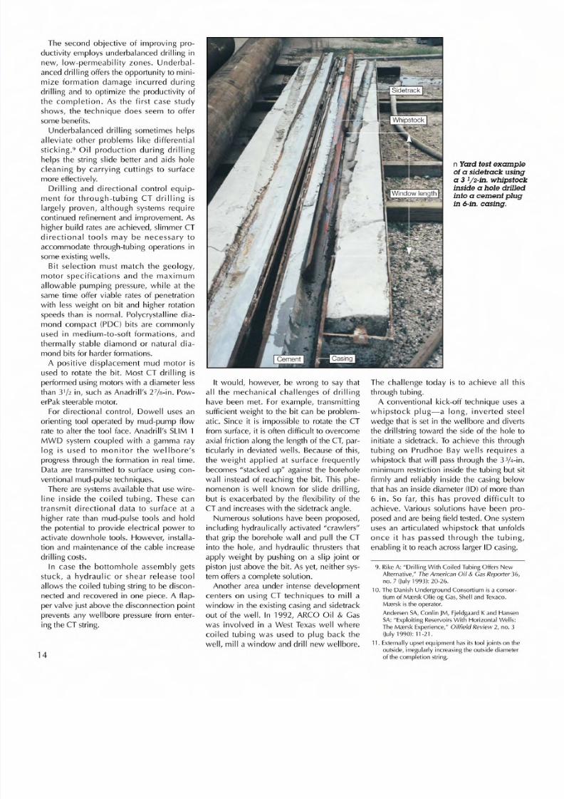
centers on using CT techniques to mill awindow in the existing casing and sidetrack
out of the well. In 1992, ARCO Oil & Gaswas involved in a West Texas well wherecoiled tubing was used to plug back thewell, mill a window and drill new wellbore.
n Yard test exampleof a sidetrack usinga 3 1/2-in. whipstockinside a hole drilledinto a cement plugin 6-in. casing.
The challenge today is to achieve all thisthrough tubing.A conventional kick-off technique usesa
whipstock plug-a long, inverted steelwedge that is set in the wellbore and divertsthe drillstr ing toward the side of the hole toinitiate a sidetrack. To achieve this throughtubing on Prudhoe Bay wells requires awhipstock that will passthrough the 3 3/4-in.minimum restriction inside the tubing but sitfirmly and reliably inside the casing below
that has an inside diameter (10) of more than6 in. So far, this has proved difficult toachieve. Various solutions have been pro-posed and are being field tested. One systemuses an articulated whipstock that unfoldsonce it has passed through the tubing,enabling it to reach acrosslarger 10 casing.
9 . R ike A : "D rilling W ith C oile d Tu bing O ffers N ewAlternative," T he A me rica n O il& G as R ep orte r 3 6,n o. 7 (J uly 1 99 3): 2 0-2 6.
1 0. T he D an is h U nd erg ro un d C on so rtiu m is a c on so r-tiu m o f M acrsk O lie og G as, S he ll a nd Texaco.M iE rs k i s t h e o pe ra to r.
A nd ers en S A, C on lin JM, F je ld ga ard K a nd H an se nSA: "E xp lo it in g R es er vo ir s With H o riz on ta l We ll s:Th e MiE rs k Exp e ri en c e, " O il fie ld R e vie w2, no. 3( Ju ly 1990 ): 11- 21 .
1 1. E xte rn ally u ps et e qu ip me nt h as its to ol jo in ts o n th eo uts id e, ir re gu la rl y in cr ea si ng th e o ut sid e d iame te ro f t he c omple ti on s tr in g.
8/6/2019 Coiled Tubing Center Stages
http://slidepdf.com/reader/full/coiled-tubing-center-stages 7/15
Dowell is currently developing two othersolutions:• A hard and nonbrittle proprietary cementplug is set downhole so that a CT millingassembly is deflected against the casingwall to cut a window-two field testshave been carried out so far.
• The inside diameter of the casing is
reduced to accommodate a normal butslim whipstock that passeseasily throughthe production tubing.In this second solution, a conventional
cement plug is set in the liner below thetubing. With CT, an oriented 3 3/4-in. hole isdrilled against the side of the casing throughwhich the sidetrack must go. Then a 3'/2-in.whipstock isrun on coiled tubing. An MWDsystem and orienting tool ensure that thewhipstock is set in the hole in the cementplug sothat itsface isadjacent to the casingwall. This is then drilled in the usual way to
kick off the well ( pr ev ious page ).Development of CT drilling is not exclu-
sive to Alaska. For example, in the NorthSea, the Danish Underground Consortiumis turning to the technique asan alternativeto its pioneering strategy based on long,conventionally drilled horizontal sectionscompleted so that many individual zonesmay be separately fractured.w Becausethese stimulation treatments and all theassociated hardware can be expensive,operator MHsk Olie og Gas believes that anetwork of slimhole wells drilled quicklyand underbalanced with coiled tubing maybe more cost-effective.To evaluate this development strategy,
Dowell and Anadrill drilled the first success-ful CT drilling offshore development well inthe North Sea. The well was completed inMay 1994 on MHsk's Gorm platform andinitially produced some 3000 BOPD-up tofour times the anticipated level (see "C TDrilling Offshore Denmark," next page ).To date, CT drilling has not been used asa
major exploration drilling tool. One factor
that limits its usefulness for explorationdrilling is the maximum openhole diameterpossible. This is increasing as larger diame-ter coiled tubing becomes available. With23/8 -in. tubing, a vertical open hole of up to8'/2 in. may be drilled. Because it is stifferand can extend farther before lock up, largerdiameter CT also allows longer horizontalsections to be drilled. However, horizontaldrilling necessitatesmore trips into the welland more cycling of the CT over the goose-neck. And the larger the CT diameter, the
O ctober 1994
more it is liable to suffer from fatigue duringhorizontal drilling.But another important parameter affects
CT durability: the internal tubing pressureatthe time of bending. The higher the pres-sure, the greater the fatigue. This, too, isrelated to the tubing diameter because inter-nal pressure depends on the flow rate
required to drive the downhole motor,which is a fixed value depending on themotor type and diameter. Larger diametertubing can achieve the required flow rate ata lower internal pressure than its slimmercounterpart, thus reducing fatigue.In short, there is an optimum tubing size
for any flow rate, and therefore for anygiven motor. All these factors, and manyothers, are taken into consideration byDowell's design software when planning thedrilling program and choosing the bottom-hole assembly and CT type. To date, the
reduced life expectancy of coiled tubinglarger than 23 /8 in. limits its use for CTdrilling in horizontal wells.
Delivering Coiled Tubing CompletionsThe availability of larger CT-up to 3'/2- in.diameter-has sparked interest in anothermajor advance: underbalanced coiled tub-ing completion. Like CT drilling, this usesthe coiled tubing unit's well control capabil-ity to safely run the completion. There aretwo basic CT completion options .
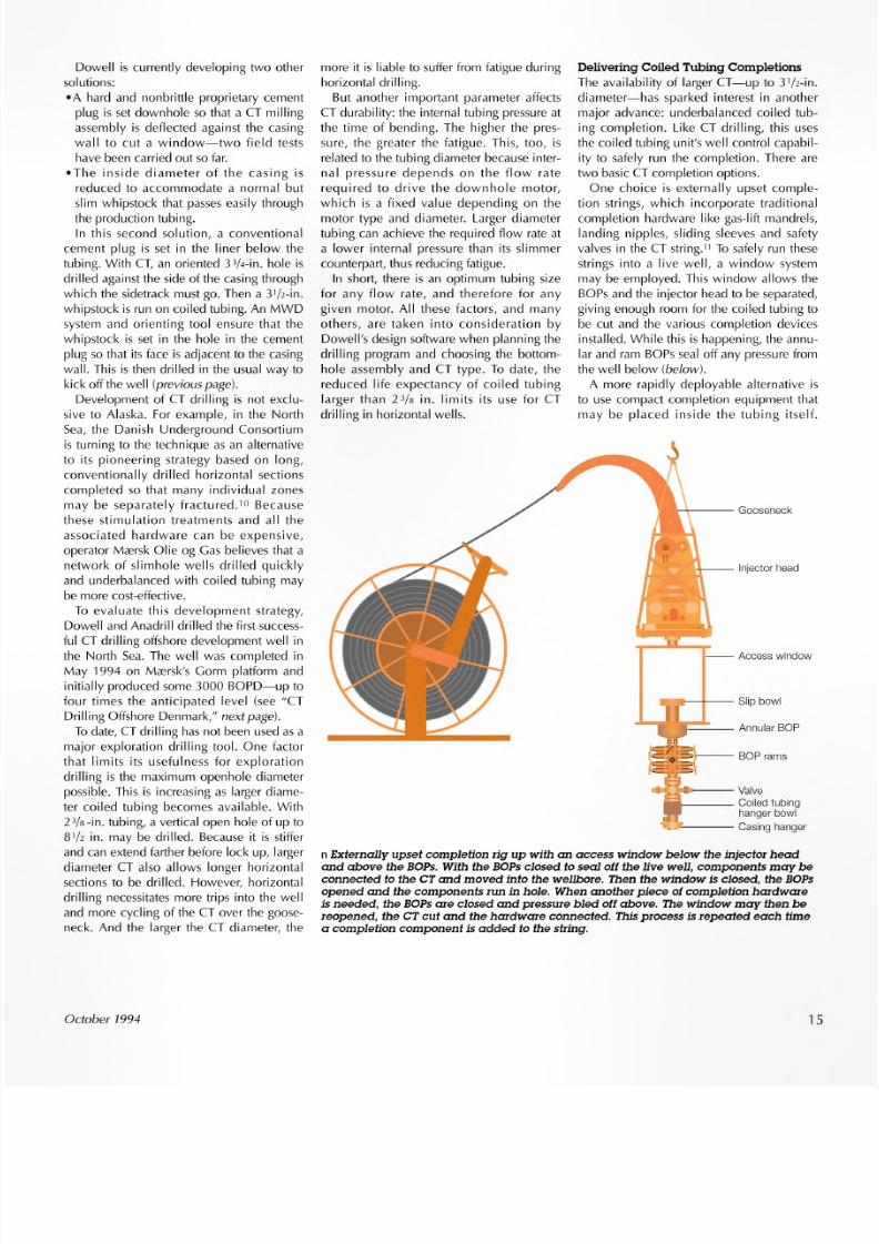
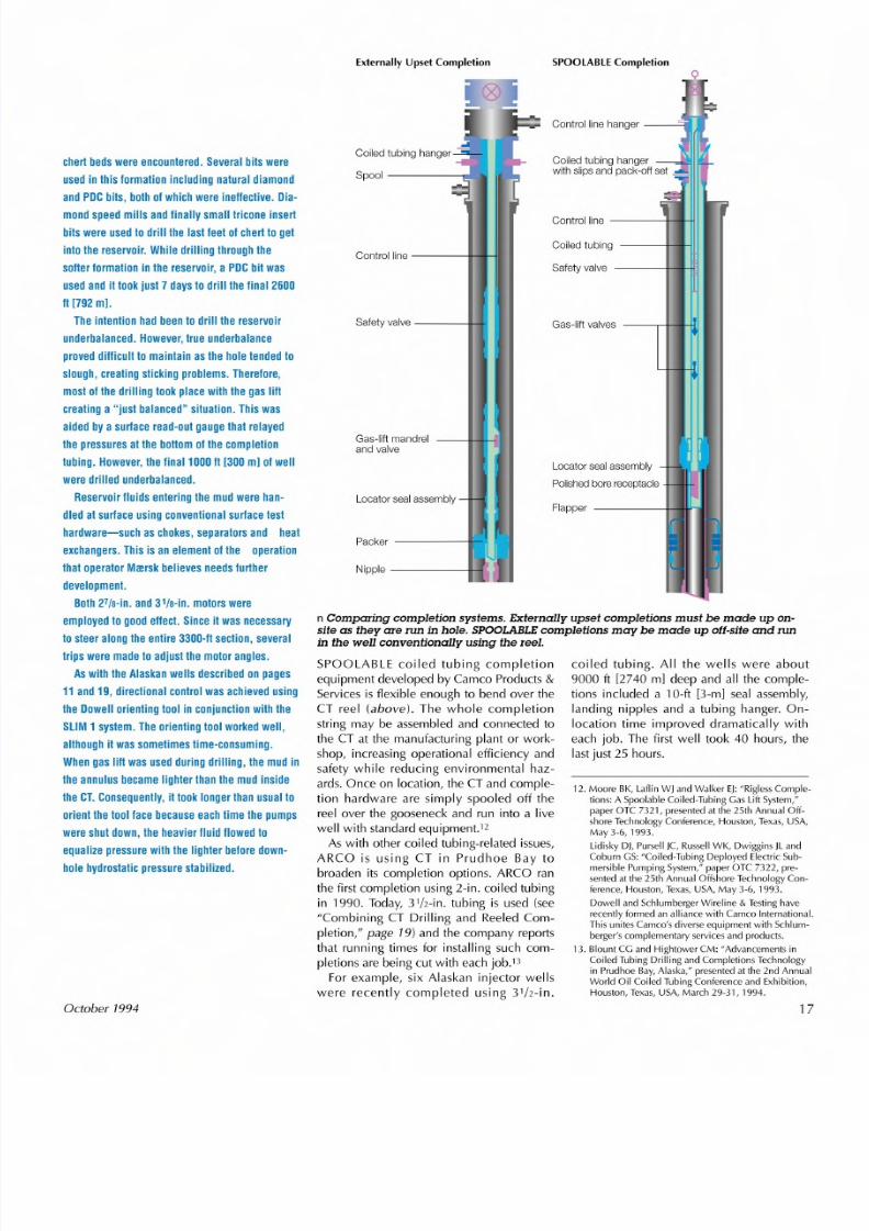
One choice is externally upset comple-tion strings, which incorporate traditionalcompletion hardware like gas-lift mandrels,landing nipples, sliding sleeves and safetyvalves in the CT string." To safely run thesestrings into a live well, a window systemmay be employed. This window allows theBOPsand the injector head to be separated,giving enough room for the coiled tubing tobe cut and the various completion devicesinstalled. While this is happening, the annu-lar and ram BOPsseal off any pressurefromthe well below (be/ow).
A more rapidly deployable alternative isto use compact completion equipment thatmay be placed inside the tubing itself.
I n jec to r head
A cc es s w in dow
):: ;U :: r-- --- - Valv e
_1---- Coi led tubingh an ge r b ow l
"'--'1>----- Ca si ng h ang er
n Externally upset completion rig up with an access window below the injector headand above the BOPs.With the BOPsclosed to seal off the live well, components may beconnected to the CT and moved into the wel lbore. Then the window is closed, the BOPsopened and the components run in hole. When another piece of completion hardwareis needed, the BOPs are closed and pressure bled off above. The window may then bereopened, the CT cut and the hardware connected. This process is repeated each timea completion component is added to the string.
15
8/6/2019 Coiled Tubing Center Stages
http://slidepdf.com/reader/full/coiled-tubing-center-stages 8/15
CT Drilling Offshore Denmark
T he firs t s uc ce ss fu l N o rth S e a C T-d rille d w e ll e m p lo ye d " iu st b a la nc ed " d rillin g to d eliv er31/z -in . o pe n h ole .
Ver ti cal Sec tion5000
.;::
.J::
0.Q J
o 6500
7000
o 1000 2000 3000 4000
Horizonta l s tep-out , f t
5000
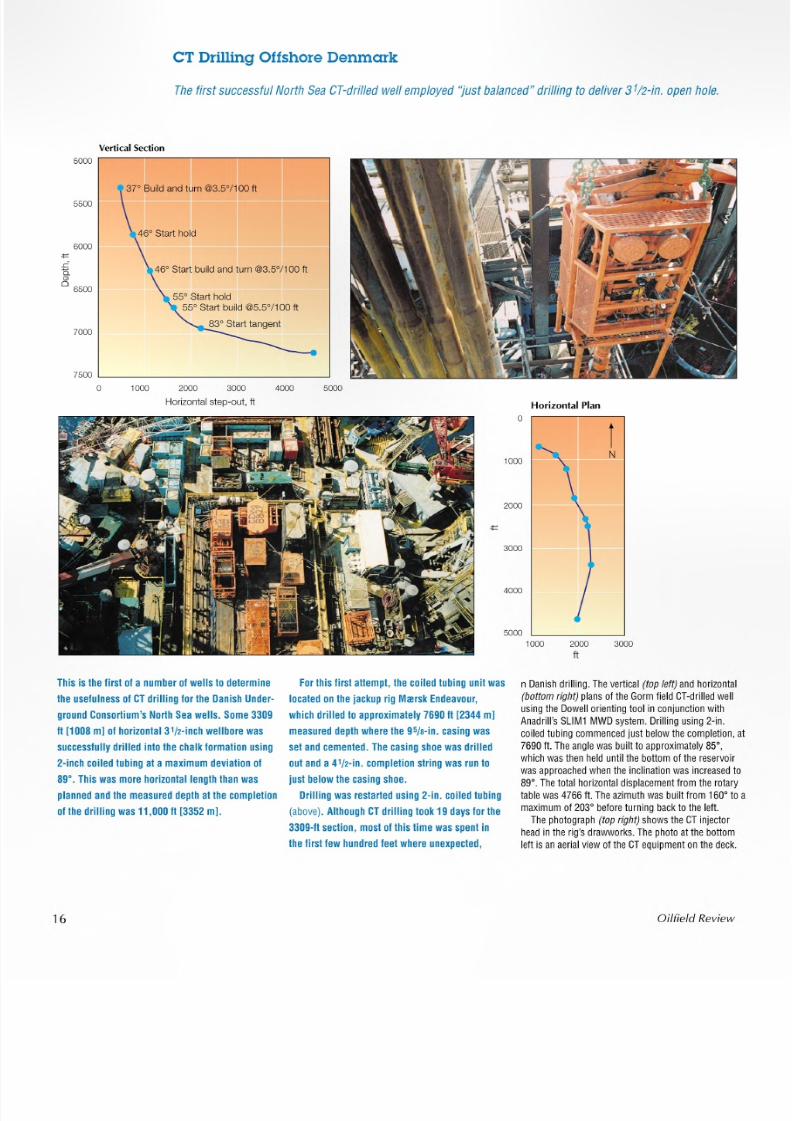
This is the first of a number of wells to determine
the usefulness of CT drilling for the Danish Under-
g ro und Con sortium 's North S ea w ells. Some 33 09
II [1008 ml of horizontal 31/2 -inch w ellbore w as
su ccessfully drille d in to the chalk form ation usin g
2-inch coiled tubing at a maximum deviation of
89° . This was m ore horizontal length than was
p lan ned an d the measured d epth at the completion
of the drilling was 11,000 II [3352 ml,
Horizo nta l p lan
o
1000
rN
2000
3000
4000
5000
1000 2000
f t3000
For this first attem pt, the coiled tubing unit was
locate d on the jacku p rig M re rsk E nde avour,
which drilled to approximately 7690 II [ 2344 ml
measured depth where the 95/s-in. ca sing w as
se t and cemente d. T he casing sho e w as drille d
out and a 41/2-in. com pletion string was run to
ju st below the ca sing shoe .
D rillin g w as re sta rted usin g 2-in. co iled tu bing
(above). Although CT drilling took 19 days for the
3309-11 section, m ost of this time was spent in
the first few hun dred feet w here une xpe cted,
16
n Danish dril ling . The ver tical( top left)and horizontal(bottom right)p lans o f th e Gorm fie ld CT-dr ille d wellu sing th e Dowell o rie ntin g tool in con junc tio n w ithAnadr ill' s SLlM1 MWD system. D rillin g u sing 2 -in .co ile d tubing commenced ju st b elow th e comple tio n, a t7690 ft. The ang le was built to app roximate ly 85° ,
which was th en held until th e bot tom o f th e r es er vo irwas app ro ached when th e in clin atio n was in cre as ed to89° . The to ta l horiz on ta l d isp la cement fr om the r ot ar y
table w as 4766 ft. The azimuth was built from 160° to amaximum of 20 3° b efore turning ba ck to th e left.The photograph ( top right)shows the CT in jector
h ead in th e r ig 's d rawwork s. The pho to a t th e bottom
le ft is an ae rial view of th e CTe qu ipmen t on the deck.
Oilfie ld Review
8/6/2019 Coiled Tubing Center Stages
http://slidepdf.com/reader/full/coiled-tubing-center-stages 9/15
chert beds were encountered. Several bits were
used in this lormation including natural diamond
and PDCbits , both0 1which were ineflective . Dia-
mond speed mil ls and linally small t ricone inser t
b its were used to d rill the la st leet0 1che rt to get
into the reservoir. While dri ll ing through the
sol ler lormation in the reservoir, a PDCbit was
used and it took just7 days to d rill the linal 2600
It [ 792 m l ,
The intention had been to dri ll the reservoir
underbalanced. However, true underbalance
proved d illicult to main ta in as the hole tended to
slough, creating sticking problems. Therefore,mos t o f the d rilling took p lace with the gas lilt
creat ing a "just balanced" situation. This was
aided by a sur lace read-out gauge that relayed
the pressures at the bot tom0 1the completion
tubing. However, t he final 1000 II [300 ml0 1well
were drilled underbalanced.
Reservoir l Iuids enter ing the mud were han-
dled at surface using conventional surface test
hardware- such aschokes , separato rs and hea t
exchanger s. This is an e lement o f the ope ra tion
that operator Mrersk believes needs furtherdevelopment.
Both 27ts-in. and 31ts-in. motors were
employed to good eflect. Since i t was necessary
to steer along the entire 3300-11section, several
t rips were made to adjust the motor angles.
As with the Alaskan wel ls descr ibed on pages
11 and 19, directional control was achieved using
the Dowel l orienting tool in conjunction with the
SLIM 1 system. The orienting tool worked wel l,
although it was sometimes time-consuming.
When gas lift was used dur ing drilling, the mud in
the annulus became l ighter than the mud inside
the CT.Consequently, i t took longer than usual to
o rient the tool face because each t ime the pumps
were shu t down, the heavie r lIu id lIowed to
equalize pressure with the l ighter before down-
hole hydrostatic pressure stabilized.
October 1994
Ex te rnal ly Upse t Comp le ti on
Coile d tu bin g h an ge r
Gas- li ft mandrela nd v alv e
Con tr ol lin e------1. ..H1
Sa fe ty va lve ---~I
Loca to r s eal a s sembly
SPOOLABLE Completion
Coile d tu bin g h an ge rw ith s lip s a nd p ac k- off s et
Sa fe ty va lve
Co il ed tub ing ----Ir.H
Gas- li ft v a lve s ----rl __ -HI
Loca to r s ea l a s semb ly
Polished bore receptac le
n Comparing completion systems. Externally upset completions must be made up on-site as they are run in hole. SPOOLABLEcompletions may be made up off-site and runin the well conventionally us ing the reel .
SPOOLABLE coiled tubing completionequipment developed by Camco Products &Services is flexible enough to bend over theCT reel (above). The whole completionstring may be assembled and connected tothe CT at the manufacturing plant or work-
shop, increasing operational efficiency andsafety while reducing environmental haz-ards. Once on location, the CT and comple-tion hardware are simply spooled off thereel over the gooseneck and run into a livewell with standard equipment.t-As with other coiled tubing-related issues,
ARCO is using CT in Prudhoe Bay tobroaden its completion options. ARCO ranthe first completion using 2-in. coiled tubingin 1990. Today, 3 1/2-in. tubing is used (see"Combining CT Drilling and Reeled Com-pletion," page 19) and the company reports
that running times for installing such com-pletions are being cut with each job."For example, six Alaskan injector wells
were recently completed using 3 1/2-in.
coiled tubing. All the wells were about9000 ft [2740 rn] deep and all the comple-tions included a 10-ft [3-m] seal assembly,landing nipples and a tubing hanger. On-location time improved dramatically witheach job. The first well took 40 hours, the
lastjust 25 hours.
1 2. M oore B K, L aflin W J a nd Walk er E J: "R igle ss C om ple-tio ns : A S po ola ble C oile d-T ub in g G as L ift S ys te m,"paper OTC 7321, presented at the 25th Annual Off-s ho re Tec hn olo gy C onfe re nc e, H ou sto n, Tex as , U SA ,
M ay 3 -6, 1 993 .
L id is ky D J, P urs ellJC ,R uss ell W K, D wig gins J L a ndC obu rn G S: "C oiled -T ub ing D eploy ed E le ctric S ub -
m ersib le P um ping S ystem ," p ap er O TC 73 22 , pre -s ented a t t he 2 5th A nnua l O ffs hore T ech nolo gy C on-fere nce , H ou sto n, T ex as, U SA , M ay 3 -6 , 19 93 .
D ow ell a nd S ch lu mb erg er W ire lin e& Te st in g h a ve
re ce ntly fo rm ed a n a llia nc e w ith C am co In te rn atio na l.T his u nite s C am eo 's d iv ers e e qu ip me nt w ith S ch lu m-
b erg er' s c om p lem en ta ry s er vi ce s a nd p ro du ct s.
13. Blount C G and Hightow er C M: "Advancem ents inC oile d T ub ing D rillin g a nd C orn ple tio ns Tec hn olo gy
in P ru dh oe B ay , A la sk a," pre se nte d a t t he 2 nd A nnu alWorld O il C oile d T ub in g C on fe re nc e a nd E xh ib itio n,H ou st on , Tex as , U SA , M a rc h 2 9-3 1,1 99 4.
17
8/6/2019 Coiled Tubing Center Stages
http://slidepdf.com/reader/full/coiled-tubing-center-stages 10/15
Dep th e nc od er m ou nte do n in je cto r h ea d
C oile d tu bin g u nitd ep th moni to r
000.0
J un ct io n b ox
L og gin g d ata fromreel collector
D ow ell d ata re co rd in g s ys tem
/ . - " " ,I ,\ ...-'
D ep th s ign al s en t to lo gging un it
Logging and Perforating with
Coiled TubingLike CT drilling, coiled tubing logging hascome of age only in the 1990s. One of itskey selling points revolves around the stiff-
nessof the tubing, enabling penetration intohorizontal and high-angle sections. Addi-tionally, wireline inside coiled tubing offersthe potential to pump fluids downhole andlog at the sametime.i-Successful application of CT logging
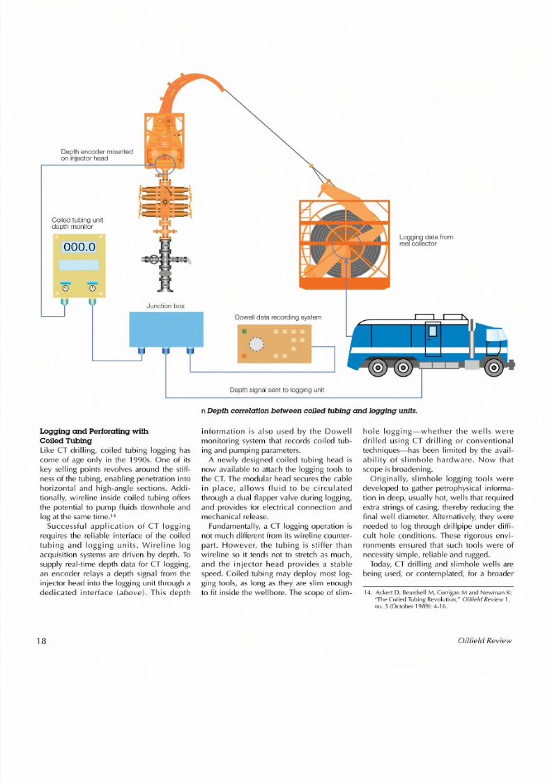
requires the reliable interface of the coiledtubing and logging units. Wireline logacquisition systems are driven by depth. Tosupply real-time depth data for CT logging,an encoder relays a depth signal from theinjector head into the logging unit through adedicated interface (above). This depth
18
n Depth correlation between coi led tubing and logging units.
information is also used by the Dowellmonitoring system that records coiled tub-ing and pumping parameters.A newly designed coiled tubing head is
now available to attach the logging tools to
the CT. The modular head secures the cablein place, allows fluid to be circulatedthrough a dual flapper valve during logging,and provides for electrical connection andmechanical release.Fundamentally, a CT logging operation is
not much different from its wireline counter-part. However, the tubing is stiffer thanwireline so it tends not to stretch as much,and the injector head provides a stablespeed. Coiled tubing may deploy most log-ging tools, as long as they are slim enoughto fit inside the wellbore. The scope of slim-
hole logging-whether the wells weredrilled using CT drilling or conventionaltechniques-has been limited by the avail-ability of slimhole hardware. Now thatscope is broadening.
Originally, slimhole logging tools weredeveloped to gather petrophysical informa-tion in deep, usually hot, wells that requiredextra strings of casing, thereby reducing thefinal well diameter. Alternatively, they wereneeded to log through drillpipe under diffi-cult hole conditions. These rigorous envi-ronments ensured that such tools were ofnecessity simple, reliable and rugged.Today, CT drilling and slimhole wells are
being used, or contemplated, for a broader
14. Acker t D, Beardse ll M, Corrigan M and Newman K:"The Coiled Tubing Revolution,"
Oilf ie ld Review1,
no. 3 (October 1989): 4-16.
O ilfie ld R ev iew
8/6/2019 Coiled Tubing Center Stages
http://slidepdf.com/reader/full/coiled-tubing-center-stages 11/15
Combining CT Drilling and Reeled Completion
We ll d rille d o ve rb ala nc e d a nd co m ple te d u sin g 2 -in . a nd 31/2 -in . c oile d tu b in g , re sp e ctiv e ly
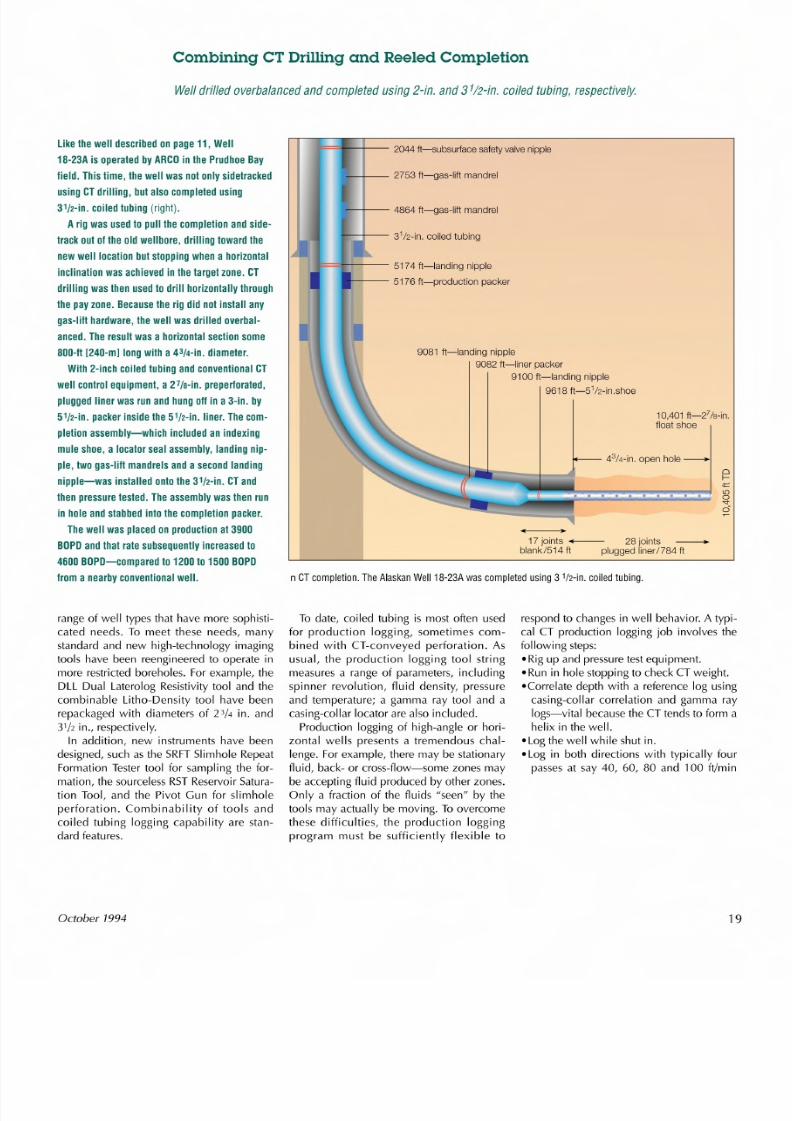
l ik e th e w e ll d es cr ib ed o n p ag e 1 1, W e ll
1 8-2 3A is o pe ra te d b y A R C O in th e P ru dh oe B ay
fie ld . T h is t im e , th e w e ll w a s n o t o n ly s id e tra c ke d
u s in g C T d rill in g , b u t a ls o c o m p le te d u s in g
31/2 -in . c o ile d t ub in g( r i g h t ) .
A rig w a s u se d to p ull th e c om p le tio n a nd s id e-
tra c k o u t o f t h e o ld w e llb o re , d ril lin g to w a rd th e
n e ww e l l l oc a ti onb u t s to p pin g w h e n a h o riz o nta l
in c lin a tio n w a s a ch ie v ed in th e ta rg e t z o ne . C T
d rillin g w a s th e n u s ed to d ril l h o riz o nta lly th ro u gh
th e p ay z on e. B e ca us e th e r ig d id n o t in s ta ll a ny
g a s-li lt h a rd w a re , th e w e ll w a s d rille d o v erb a l-
a nc ed . T h e re su lt w a s a h o r iz on ta l s ec tio n s om e
8 0 0 - 1 t[ 2 4 0 -m ]l o ngw ith a 43/ 4- in . d i am e t e r .
W i th 2 -in c h c o ile d tu b in g a n d c o nv e ntio n al C T
w e ll c o n tr ol e q u ip m e n t , a 2 7 /s -in . p r ep e rf or ate d ,
p lu gg ed lin er w a s ru n a nd h un g o il in a 3 -in . b y
51/2 -in . p ac ke r in s id e th e 51/2 -in . l in e r. T h e c o m -
p le tio n a ss em b ly -w h ic h in clu de d a n in de xin g
m u le s ho e , a lo ca to r s ea l a ss em b ly , la nd in g n ip -
p le , tw o g as -lil t m a n dre ls a nd a s ec on d la nd in g
n ip ple -w a s in sta lle d o nto th e 31/2 -in . C T a nd
th en p re ss ure te s te d . T he a ss em b ly w a s th en ru n
in h o le a nd s ta bb ed in to th e c om p le tio n p ac ke r.T he w e ll w a s p la ce d o n p ro du c tio n a t 3 90 0
B O P D a n d th a t ra te s u bs eq u en tly in c re a se d to
4 6 0 0 B OP D-c om p a re d to 1 2 0 0 to 1 5 0 0 B OP D
fro m a n e arb y c o nv e ntio n al w e ll .
range of well types that have more sophisti-cated needs. To meet these needs, manystandard and new high-technology imagingtools have been reengineered to operate inmore restricted boreholes. For example, the
DLL Dual Laterolog Resistivity tool and thecombinable Litho-Density tool have beenrepackaged with diameters of 2 3/4 in. and31 /2 in., respectively.In addition, new instruments have been
designed, such asthe SRFTSlimhole RepeatFormation Tester tool for sampling the for-mation, the sourceless RSTReservoir Satura-tion Tool, and the Pivot Gun for slimholeperforation. Combinability of tools andcoiled tubing logging capability are stan-dard features.
October 1994
_-£-- 2753ft-gas-lift mandrel
F==-B-- - 2044ft-subsurfacesafetyvalvenipple
9081ft-Ianding nipple9082ft-liner packer
9100ft-Ianding nipple9618ft-5 1/2-in.shoe
I-- £-- 4864ft-gas-lift mandrel
'==="1--+-- 5174ft-Ianding nipple
--+-- 5176ft-production packer
10.401t_27/s-in.floatshoe
43 /4-in.openhole ----+
oI-;=L[)o
'":i
17joints --- 28 joints ___blank/514ft pluggedliner1784t
n C T c om p le tio n. T he A la sk an W e ll 1 8- 2 3A w a s c om p le te d u sin g 3 1 /2 -in . c oile d tu bin g .
To date, coiled tubing is most often usedfor production logging, sometimes com-bined with CT-conveyed perforation. Asusual, the production logging tool stringmeasures a range of parameters, including
spinner revolution, fluid density, pressureand temperature; a gamma ray tool and acasing-collar locator are also included.Production logging of high-angle or hori-
zontal wells presents a tremendous chal-lenge. For example, there may be stationaryfluid, back- or cross-flow-some zones maybe accepting fluid produced by other zones.Only a fraction of the fluids "seen" by thetools may actually be moving. To overcomethese difficu Ities, the production loggi ngprogram must be sufficiently flexible to
respond to changes in well behavior. A typi-cal CT production logging job involves thefollowing steps:• Rig up and pressuretest equipment.• Run in hole stopping to check CTweight.
-Correlate depth with a reference log usingcasing-collar correlation and gamma raylogs-vital because the CT tends to form ahelix in the well .
• Lo g the well while shut in..Log in both directions with typically fourpassesat say 40, 60, 80 and 100 ft/min
19
8/6/2019 Coiled Tubing Center Stages
http://slidepdf.com/reader/full/coiled-tubing-center-stages 12/15
[12, 18, 24 and 30 m/minl with the wellflowing. The intervals between data col-lection may be decreased or the loggingspeed increased.
• Observe well anomalies, making somestationary log measurements to look forbackflow.
• Pullout of hole.
Another production-related CT loggingservice employs pulsed neutron logs andborax solution. The borax is pumped intothe CT-production tubing annulus at a pres-sure above that of the reservoir but belowthe fracturing pressure. Because borax ismore effective than reservoir fluid at slow-ing neutrons, pulsed neutron logs can tracewhere it has gone and hence confirm thelocation of a suspected channel and indi-cate high-permeabi I ity zones. With addi-tional openhole log data, initial reservoirsaturation information may also be derived.
After the production profile of a well andpotential hydrocarbon saturated zones havebeen identified, reperforation using CT-con-veyed guns may be necessary (see"CT Log-ging and Perforation in Alaska," right).
Matrix TreatmentThe most traditional of all coiled tubing ser-vices is the delivery of fluids downhole. Noaccount of the practical uses of coiled tub-ing would be complete without describingat least one pumping application-a rolethat has become more important with theproliferation of horizontal wells.As in other areas, increasingly sophisti-
cated pumping services are available. Forexample, a relatively new matrix treatmenttackles an old problem, diversion. Unless astimulation fluid is successfully diverted intothe areas that most need it, the fluid willchannel into the high-porosity, high-perme-ability formation that least requires improve-ment. Horizontal wells generally have amuch longer reservoir section than their ver-tical counterparts, so the problem of diver-
sion is proportionally more difficult. Tocompound this, few horizontal wells arecompleted in a way that allows even rudi-mentary zonal isolation.Traditionally, diverting materials-like cal-
cium carbonate or rock salt-are introducedto temporarily plug the zones of the forma-tion taking most fluid, redirecting flow tomore needy parts of the wellbore. But theplugging must be reversible-by dissolutionin acid or reservoir fluids-and leave theformation undamaged. Not an easy criterionto meet.
20
CT Logging and Perforation in Alaska
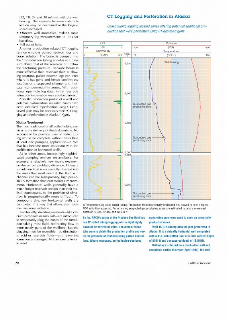
C o ile d tu bin g lo gg in g lo ca te d z on es o ffe rin g p ote ntia l a dd itio na l p
d uc tio n th at w e re p er fo ra te d u sin g C T -d ep lo ye d g un s.
CC l Pressure
-19 (V ) 1100 (PSI) 1100
G amma ray Tem e ra tu re0 (GAP) 200 1:600 175 185
It
12,200
12,400
S us pe ct ed g as -- -- +\p ro du ci ng z on e
'------'----:__ ___JLJ 12,500 '------' ___.__-'---_---'--- __ -'-- ___J
,---- ---- --;;;; ;;; ;;0" 13,400 ,--,-------,----,---,---------,
13,500
S us pe ct ed g as ----_p ro du ci ng z on e
n T em p er a tu re lo g u sin g c oile d tu b in g. P ro du ctio n fro m th is v ir tu al ly h or iz o n ta l w e ll p ro ve d toG O Rra tio th an e xp ec te d . F ro m th is lo g s us pe cte d g as p ro du cin g zo ne s a re e st im a te d to b e a t a md ep th o f12,335, 12,450 a n d 13,530 ft .
S o fa r, A R C O 's s ec to r o f th e P ru dh oe B ay fie ld h as p erfo ra tin g g un s w e re u se d to o pe n u p p
ru n 1 2 c oile d tu bin g lo gg in g jo bs in e ig ht h ig hly p ro du ct iv e z o ne s.
d ev ia te d o r h o r iz on ta l w e lls . T he a im s o f t he seWell 15-07Ae x em p lifie s th e jo b s p e rfo rm e d in
jo bs w e re to o bta in th e p ro du ctio n p ro file a nd v er - A la sk a.I t is a v ir tu a lly h o riz o n ta l w e ll c o m p le te d
ify th e p re se nc e o f c ha nn e ls u s in g p u ls ed n eu tro n w ith a 4 1/2 -in ch s lo tte d lin era t a lo la l v e rtic a l d e plh
lo gs . W h ere n ec es s a ry , c o ile d tu bin g-d ep lo ye d o f 8 76 1 II a n d a m e a s ure d d ep lh o f 1 3,5 4
D rille d a s a s id et ra ck to a m u ch o ld er w e ll a nd
c o m p le le d e a rlie r th is y e ar(A p ril 1 9 94 ),th e w e ll
Oilfie ld Review
8/6/2019 Coiled Tubing Center Stages
http://slidepdf.com/reader/full/coiled-tubing-center-stages 13/15
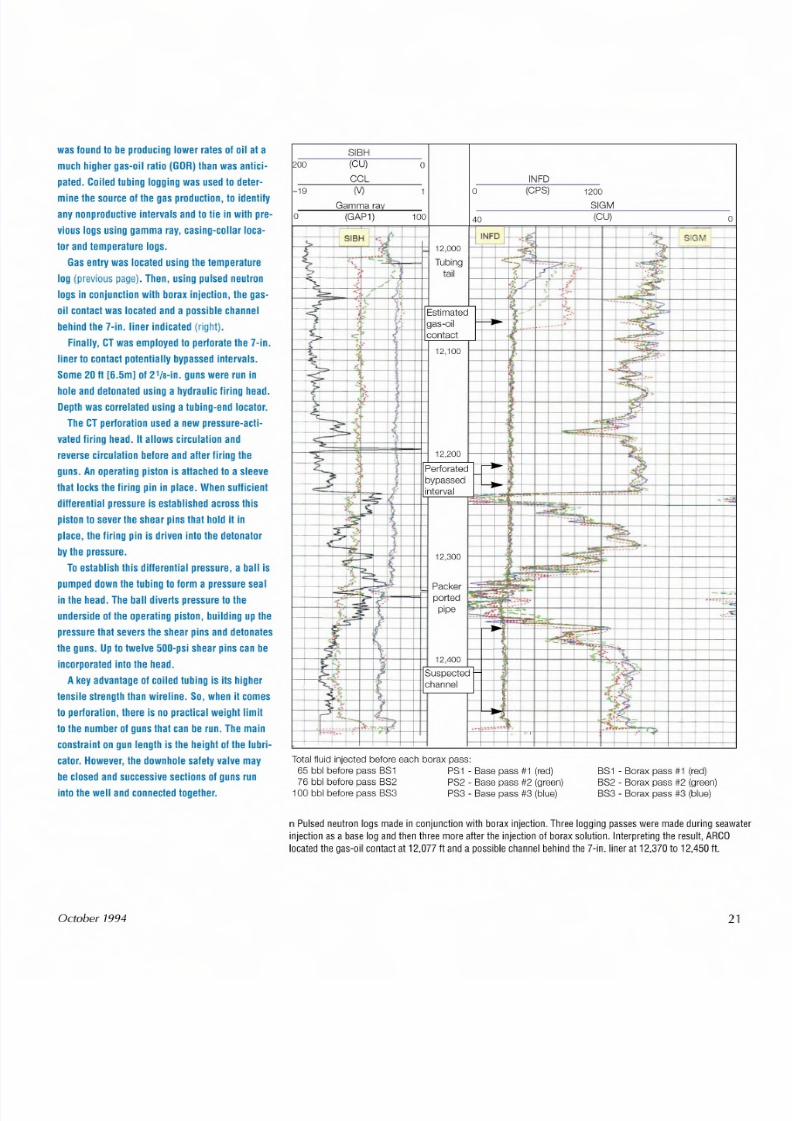
w as fo un d to b e p ro du cin g lo w er r a te s o f o il a t a
m u c h h ig h er g a s -o il ra tio (G O R ) th an w a s a ntic i-
p a te d . C o ile d tu b in g lo g gin g w a s u se d to d e te r-
m in e th e s ou rc eo f t he g a s p r o d u ctio n , to id e n tify
a ny n o np ro d uc tiv e in te rv als a nd to tie in w ith p re -
v io u s lo g s u s in g g am m a ra y, c as in g -c olla r lo ca -
to r a nd te m p era tu re lo g s.
G a s e n tr y w a s lo c ate d u s in g th e te m p e ra tu re
lo g (previous page). T h e n, u s in g p u ls ed n e utr on
lo g s in c o nju n ctio n w i th b o ra x in je ctio n , th e g a s-
o il c on ta ct w a s lo ca te d a nd a p o ss ib le c ha nn el
b e h in d th e 7 -in . lin e r in d ic ate d(right).
F in a lly , C T w a s e m p lo ye d to p er fo ra te th e 7 -in .l in e r to c o n ta c t p o te n tia lly b y p a ss e d in te rv a ls .
S om e 2 0It [ 6 . 5m ]of 21/a-in. g un s w ere ru n in
h o le a nd d eto n ate d u s in g a h yd ra u lic fir in g h ea d .
D e p th w a s c o rre la te d u s in g a tu b in g -e n d lo c ato r.
T h e C T p e rfo ra tio n u s ed a n e w p re ss u re -a c ti-
v ate d fir in g h e ad . It a llo w s c ir cu la tio n a n d
r ev er se c ir cu la tio n b e fo re a n d a lte r fir in g th e
g u ns . A n o p er a tin g p is to n is a tta ch ed to a s le ev e
tha t locks th e fir in g p in in p la ce . W h e n s u llic ie n t
d il le re n tia l p r es s u re is e s ta b lis h e d a c ro s s th is
p is to n to s ev er th e s he ar p in s th a t h o ld it in
p la ce , th e fir in g p in is d riv en in to th e d e to n ato r
b y th e p re ss u re .
T o e sta b lis h th is d ille re n tia l p re ss u re , a b a ll is
p um p ed d ow n th e tu b in g to fo rm a p re ss ur e s ea l
in th e h ea d . T h e b all d iv er ts p re ss ur e to th e
u n d e r s i d eo f t he o p er atin g p is to n , b u ild in g u p th e
p re ss u re th a t s ev er s th e s h ea r p in s a n d d e to n ate s
th e g un s . U p to tw e lv e 5 00 -p si s he ar p in s c an b e
in c or po ra te d in to th e h e ad .
A k ey a dv an ta ge o f c oile d tu b in g is its h ig h er
te ns ile s tr e ng th th an w ire lin e . S o , w h en it c om e s
to p e rfo ra tio n , th e re is n o p ra c tic alweigh t l imit
to th e n um b er o f g u ns th at c a n b e ru n . T he m a in
c on s t ra in t o n g u n le ng th is th e h e ig h to f t he l ub r i -
c ato r. H o w ev er , th e d o w nh o le s afe ty v alv e m a y
b e c lo se d a nd s uc ce ss iv e s ec tio n s o f g u ns ru n
in to th e w e ll a n d c o nn e cte d to g e th e r.
October 1994
INFO
SIBH200 (CU) 0
CC l-19 (V ) 1
Gamma ra~0 (GAP1) 100
(CPS) 1200
SIGM(CU) o0
~..,.~--"-I-~ .~ L '>+ '~ ..~ I: :',f; . SIGM}-h.J?'--l.....-...,.. ..~,.•HIH+I 12,000 H-----t---+--;;;:~d: _t__+_-'--.J.-;H--J----'~"l,'f--=r=I=--I
I= - : ' S . ~ I=~" ; ; ,~-~tJttlTubing 1--j-t-;:t:'_~-F;: __:i . :;:;:0:::--± , -=~ t - .- - r - t ~+ - - __ t _ -~~ · -==I=;===i? 'tail r ..> ' " ._ 1 ;<~ 1 1
f---.':;-'>!'.~-I-_',i1-+-"" l fC - - 1-+-+--t:\I. '+.f'~ l r ~~~ '. J ); I 'j-'-" ~
-;fY-t--+_Ol·'i-,~__j__H.t-, -+t.IcE~st;;;:im;;;:at~ed;t]-HH""_~_-h-':::I-'-+--+t~~:_.+-.+--1-- --"-'--~"fi:"'~~C:>"""_-+--if---1I---f*--+-I-+~:F'-----+-}..,I--l-Ilgas-oil i :±=-- . . ,_~t - - . - - -1_ . ' - . - -+-_-_.;;.;"+----1--I-+=.-.-...IIi- Gi:"1:E=i--+--+--'-~1
·~~~-,~~'t.-_HIH-~ITco~n~ta~ct~~+-+~+-1_~-+-+_I_~~~~·~~~-_.~; ,--f----tJ---1
J ,.' I : .: ;~ I_ _ _ _ _ },_ 1 _ ~ ,: --t---t1+----hH 12,100 _ ~ .•,. . < ;_ I' .. J~r'-< l--t-t--'.!'t-t-+-t--t--t--+-f-' -FI--=.::o,a?:,.o;_.t-:~-+-+----I
? -", =- .....~.._1___,--t~·,_+-+--r---1--+-I--+----1~~.~~---------1
I1
I
1
I ~e:a, II
II
Total fluid injected before each borax pass:65 bbl before pass BS1 PS1 - Base pass #1 (red)76 bbl before pass BS2 PS2 - Base pass #2 (green)100 bbl before pass BS3 PS3 - Base pass #3 (blue)
BS1 - Borax pass #1 (red)BS2 - Borax pass #2 (green)BS3 - Borax pass #3 (blue)
n Puls ed neu tron logs made in con junct io n w ith bor ax in je ctio n, Thr ee logg ing pas se s were made dur ing s eawa te rin je ctio n a s a b as e log and t hen th re e mor e a ft er th e in je ct io n o f borax so lu tio n. In te rp re tin g th e r es ult, ARGO
loca te d th e g as- oil conta ct a t 12,077 f t a nd a poss ib le ch anne l b eh ind t he 7 -in , lin er a t 12,370 to 12,450It
21
8/6/2019 Coiled Tubing Center Stages
http://slidepdf.com/reader/full/coiled-tubing-center-stages 14/15
A successful alternative employs stablefoam that isgenerated in the "thief zones" asa diverter. Alternating stagesof acid and thefoam-made from water containing surfac-tant and nitrogen-are pumped.! ' Thediverter enters the formation that is takingfluid. Some 10 minutes or so are allowed forthe foam to build up and, when pumping
restarts with a new acid stage, a pressureincrease is seen at surface as the foamensures the acid enters some other part ofthe formation. Pressuregradually decreasesuntil it is time to pump the next foam stage.Once production starts, the foam breaksdown and flows out of the well leavingundamaged, acidized formation.Coiled tubing is an ideal way of targeting
the delivery of the treatment fluids to theformation, particularly in horizontal wells.Furthermore, because the volume inside CTis relatively small, a flexible treatment pro-
gram may be employed, based on pressureresponses observed during pumping (see"Matrix Treatment in Alberta," right).
Looking to the FutureThis tour of coiled tubing applications hasconcentrated on events in Alaska and theNorth Sea. But allover the world operatorsand service companies are using coiled tub-ing for a range of tasks that would havebeen inconceivable only a few years ago.As larger diameter tubing and the avail-
ability of hardware needed to handle itbecome more widespread, even more ser-vices will be devised and current onesimproved. For example, conventional direc-tional CT drilling techniques will bereplaced by geosteering. CT completion sys-tems will be refined and costs reduced. Log-ging with CT will become more extensive.Rigless well workover operations willbecome increasingly widespread.If they weren't so busy coping with the
present, coiled tubing engineers could lookforward to the future with excitement. -CF
15. Crowe C, Masmonteil J and Thomas R:"Trends inMatrix Acidizing," Oilfield Review 4, no. 4 (October1992): 24-40.
22
Matrix Treatment in Alberta
C T-e on ve ye d F oa mMAT tre a tm e n t a dd ed a n e stim a te d d eliv era bio f2 to 6 m i llio n s e fiD .
This case concerns a Suncor Inc. operated gas
wel l, Pine Creek 10-1-56-19-W5M, in Alber ta ,
Canada. It has a 2493-11[760-mJ horizontal sec-
t ion, dri lled through the carbonate reservoir above
the wate r leg to a measu red dep th o f 14,935 II
J4552ml.
Unl ike the usuaf s ituation, the best porosity of
Consequenlly, extensive compatibility tests
were run between the mud and proposed acid sys -
tems. The f inal t reatment design included a num-
ber of s tages:
.tu bing p ickle , which is u sed t o cle an up t he
ins ide of the coi led tubing-15% hydrochloric
acid [HCIl, inhibitor and surfactant
the hor izon ta l sec tion was believed to be a t the toe • p re llu sh , to th in the mud in the wellbore- fr ac -
o f the well r ather than the hee l. However, it was
also bel ieved that these high-potent ia l zones had
been invaded by dri ll ing mud fi lt ra te . Toenhance
product ivity, i t was important to ensure that the
a cid was pumped into th e to e o f t he well to openupf ractu re s and a llow the mud to lIow out.
Tocreate the required diversion, i t was decided
to pump a FoamMATtreatment. Foam is pumped
into the formation, blocking fur ther entry of the
acid and diver ting i t to unstimulated reservoir. To
minimize fr ic tion when pumping at the necessary
rate , 2 -in . coiled tubing was used to deliver the
l Iuids. The relat ively large CTdiameter a lso
helped avoid lock-up when running into the long
horizonta l section and offered more pul ling poten-
tia l if the s tr ing had become s tuck .The downhole assembly consisted of a nozzle,
two memory gauges separated by a knuckle [elnt ,
and a check valve. The knuckle joint added
lIexibil ity to an otherwise s ti ff assembly. Data
collected by the gauges were used a lle r the job to
analyze the bui ldup and breakdown of the forma-
t ion as success ive diversion and acid phases
were pumped.
A number of factors complicated the choice of
acid add itives -which is c rucia l to the success o f
any matr ix t reatment . First , as a lready noted, Sun-
tur ing oil , ant is ludge agent and nit rogen, creat -
ing a fo am with a qua lity o f 50%1
• Mudclean OBso lu tion, to flu sh out any remain -
ing mud in the well and wate r-we t the fo rmation
prior to the FoamMATjob-water, surfactantand solven t a sa foam of50% qua lity
• diversion stages-water and surfactant with
n itrogen as a 65% qua lity foam
• squeeze acid -15% HCI, with inhib ito r, sur fac-
tant, de-emulsifier, antisludge agent, miscible
solvent and H2S scavenger. The tota l volume of
th e a cid , some 33,025 gal [ 125 m3], was deter-
mined bya rule o f thumb and pas t exper ience of
a FoamMATjob car ried out on a nea rby o il well.
• pos tjob lIush -fr ac tu ring o il and n itrogen .
Having pickled the CTand negot ia ted someproblems running in hole caused by a hydrate
p lug, the p re flu sh was pumped with the CTon bot-
tom-a t th e end o f t he to e. Once a ll th e p re flu sh
had been displaced across the open hole, the wel l
was shut in fo r a bout 15 m inu te s to a llow it to so ak
and then f lowed backto recover any mud filt ra te .
Next the Mudclean OBstage was pumped down-
hole and displaced using nit rogen. The wel l was
then a llowed to ffow to c lean up and ano ther s tage
was pumped.
When th is had been d isplaced out o f the well,
cor suspec ted that the fo rmation had been invaded the main tr ea tmen t commenced . A ser ie s o f 15
by s ignifica nt quantitie s o f mud filtra te, which con- a lte rnating a cid -1585 gal [ 6 m3J-and diver ter
ta ined a s trong emuls ifie r likely to fo rm an emu1 - -400 gal [1.5 m3J -s tages were pumped a t 25to
sion w ith sp ent a cid . S econd , th e p re sence o f 25% 80 gal/m in [ 0.1 to 0 .3 m3/m inJ . A t t he same time,
hydrogen sulfide [H2SJ in the wel l necessi ta ted the
use of corrosion-control addit ives that may react
with other chemicals in the f luid .
Oilfie ld Review
8/6/2019 Coiled Tubing Center Stages
http://slidepdf.com/reader/full/coiled-tubing-center-stages 15/15
Duvemay
128
Beaverhiliia e
Temperatureone
D imestone
D hale
118 (DEGC)
Temperature der ivat ive-17.75 (DEGC) -17,85
- - - - - Minimum distanceWel lh ead p re ssur e
5000 (KPA) 11000
Flowing pressure
21000 (KPA) 25000
Minimum distanc e from boundary
3650 3950 4350750 3850
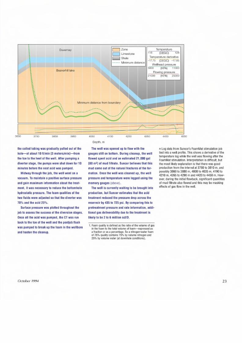
th e c oile d tu b in g w a s g ra du ally p u lle d o u t o f t he
h o le -a t a b ou t 1 0 It /m i n [3 m e te rs /m i n]- fro m
th e to e to th e h ee l o f t h e w e ll . A lte r p um p in g ad iv er te r s ta ge , th e p um p s w e re s hu t d ow n fo r 1 0
m in u te s b efo re th e n ex t a cid w a s p um p e d.
M id w ay th ro ug h th e jo b, th e w e ll w e nt o n a
v ac u um . To m a in ta in a p o sitiv e s u rfa ce p re s su re
a nd g ain m a x im u m in fo rm a tio n a bo u t th e t re at -
m e n t, i t w a s n ec es sa ry to re du ce th eb o tto m h o le
h y dro s ta tic p re ss u re . T h e fo a m q u alit ie s o f th e
tw o f lu id s w e re a d ju s te d s o th at th e d iv er te r w a s
7 0% a n d th e a c id 2 5% .
S u rfa ce p re s su re w a s p lo tte d th ro u gh o ut th e
jo b to a s se s s th e s u cc e ss o f t h e d iv ers io n s ta g es .
O n c e a ll th e a cid w as p um p ed , th e C T w a s ru n
b ac k to th e to e o f th e w e ll a nd th ep o s t j o bf l u s h
w a s p um p ed to b re ak u p t he fo am in th e w e llb ore
a n d h a ste n th e c le an u p.
October 1994
4050 4150 4250
Depth, m
T he w e ll w a s o pe ne d u p t o flo w w ith th e
g au ge s s ti ll o n b o tto m . D u rin g c le an up , th e w e ll
flo w ed s pe nt a cid a nd a n e st im a te d 2 1,0 00 g al[8 0 m3] o f m u d f il tr ate . S u n co r b e lie v es th a t th is
m u d c am e o u t o f t he n atu ra l fra c tu re s o f t he fo r-
m a tio n . O n ce th e w e ll w a s c le an ed u p , th e w e ll
p re ss u re a nd te m p era tu re w e re lo gg ed u s in g th e
m e m o ry g au ge s(above).
T he w e ll is c u rre nt ly w a it in g to b e b ro ug h t in to
p ro d uc tio n , b u t S u n c o r e s tim a te s th a t th e a c id
tre a tm e n t re d uc ed th e p re ss u re d ro p a c ro s s th e
re se rv oir b y 4 3 5 to 7 25 p si. B y c om p a rin g th is to
p re tre a tm e n t p re s su re a n d r ate in fo rm a t io n , a d di-
tio n al g a s d e liv e ra b ility d u e to th e tre a tm e n t is
lik ely to b e 2 to 6 m illio n s cf /D .
1 , F oam qua lity is d efine d a s t he ra tio o f th e v olume o f g asin the foam to the total volume of foam -ex pres sed asa f ra ct ion o r a s a per cent age, So a n it rogen-wa te r f oamo f 7 5% quality c on ta in s 7 5% byvo lume n itro ge n a nd25% by volume wat er ( at downhol e condi ti on s) ,
4450 4550
n Log data fr om Sunco r' s FoamMat st imula tio n jobtie d in to a well p ro file . This s hows a der iv ativ e o f th etemper atu re log while t he well was flowing a fte r t he
FoamMat s timula tion. Interpretat ion i s d iffi cu lt , butth e mos t lik ely exp la na tio n is th at t he re was goodpro du ctio n from th e in te rva l at 3 76 0 to 38 10 m , a nd
possibly 3860 to 3880 m, 4000 to 4035 m , 4190 to4210 m, 4265 to 4290 m and 4420 to 4450 m. How-ever, during the ini tial f lowback, signif icant quanti ties
o f mud filtr at e a ls o flowed and t his may be maskinge ffe cts o f g as flow in th e well.
23