coiled tubing dowell handbook
TRANSCRIPT

COILED TUBING CLIENT SCHOOL MANUAL
This manual has been prepared to complement the information provided through the presentations anddiscussions held during a Schlumberger Dowell Coiled Tubing Client School. The technical information withinthis manual is intended to provide a basic understanding of the equipment, tools, processes and designrequirements associated with modern coiled tubing operations. Comprehensive and detailed information, suchas that required to safely and successfully complete the design and execution of coiled tubing operations, maynot be included. Consequently, it is recommended that the local Dowell representative be consulted during thefeasibility or design preparation phase of any coiled tubing operation.
SchlumbergerDowell
CTCSM Rev A – March 1995/November 1996
Table of Contents
Section Title Page
1 Coiled Tubing and Well Control Equipment 1-12
2 Downhole Tools and Equipment 1-10
3 The Coiled Tubing String 1-19
4 Coiled Tubing Job Design 1-7
5 Conventional Coiled Tubing Applications 1-50
6 Wired Coiled Tubing Applications 1-10
7 Coiled Tubing Completions 1-15
8 Coiled Tubing Drilling 1-47
9 Appendices
I Contingency Planning 1-14
II Deployment Systems 1-18
III Coiled Tubing Unit Simulator 1-4
10 Supplementary Information
Section 1
Page 1COILED TUBING CLIENT SCHOOL MANUAL
ContentsPageContents Page
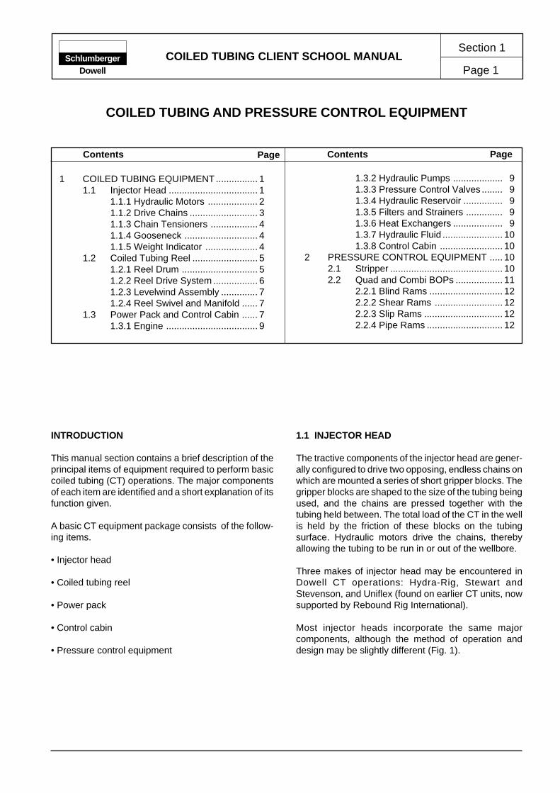
INTRODUCTION
This manual section contains a brief description of theprincipal items of equipment required to perform basiccoiled tubing (CT) operations. The major componentsof each item are identified and a short explanation of itsfunction given.
A basic CT equipment package consists of the follow-ing items.
• Injector head
• Coiled tubing reel
• Power pack
• Control cabin
• Pressure control equipment
1.1 INJECTOR HEAD
The tractive components of the injector head are gener-ally configured to drive two opposing, endless chains onwhich are mounted a series of short gripper blocks. Thegripper blocks are shaped to the size of the tubing beingused, and the chains are pressed together with thetubing held between. The total load of the CT in the wellis held by the friction of these blocks on the tubingsurface. Hydraulic motors drive the chains, therebyallowing the tubing to be run in or out of the wellbore.
Three makes of injector head may be encountered inDowell CT operations: Hydra-Rig, Stewart andStevenson, and Uniflex (found on earlier CT units, nowsupported by Rebound Rig International).
Most injector heads incorporate the same majorcomponents, although the method of operation anddesign may be slightly different (Fig. 1).
SchlumbergerDowell
1.3.2 Hydraulic Pumps ................... 91.3.3 Pressure Control Valves ........ 91.3.4 Hydraulic Reservoir ............... 91.3.5 Filters and Strainers .............. 91.3.6 Heat Exchangers ................... 91.3.7 Hydraulic Fluid ....................... 101.3.8 Control Cabin ........................ 10
2 PRESSURE CONTROL EQUIPMENT ..... 102.1 Stripper ........................................... 102.2 Quad and Combi BOPs .................. 11
2.2.1 Blind Rams ............................ 122.2.2 Shear Rams .......................... 122.2.3 Slip Rams .............................. 122.2.4 Pipe Rams ............................. 12
1 COILED TUBING EQUIPMENT................ 11.1 Injector Head .................................. 1
1.1.1 Hydraulic Motors ................... 21.1.2 Drive Chains .......................... 31.1.3 Chain Tensioners .................. 41.1.4 Gooseneck ............................ 41.1.5 Weight Indicator .................... 4
1.2 Coiled Tubing Reel ......................... 51.2.1 Reel Drum ............................. 51.2.2 Reel Drive System ................. 61.2.3 Levelwind Assembly .............. 71.2.4 Reel Swivel and Manifold ...... 7
1.3 Power Pack and Control Cabin ...... 71.3.1 Engine ................................... 9
COILED TUBING AND PRESSURE CONTROL EQUIPMENT

COILED TUBING CLIENT SCHOOLCOILED TUBING AND WELL CONTROL EQUIPMENT
Section 1
Page 2Schlumberger
Dowell
Major injector-head components include the following.
• Hydraulic motors
• Drive chains
• Chain tensioners
• Gooseneck or guide-arch
• Weight indicator
Figure 1. Hydra-Rig HR 240 injector head, side view.
1.1.1 Hydraulic Motors
The hydraulic motors provide the traction required tomove the tubing in or out of the well. By controlling thepressure and flow rate of the hydraulic fluid delivered tothe motors, the speed and, more importantly, potentialforce exerted by the injector head can be controlled.Two motors, generally synchronized through a gearbox,are used to drive the injector head.
50-in. radius gooseneck
Injector drive motor
Inside chain tensioner
Weight indicator load cell
Outside chain tensioner
COILED TUBING CLIENT SCHOOLCOILED TUBING AND WELL CONTROL EQUIPMENT Page 3
Section 1Schlumberger
Dowell
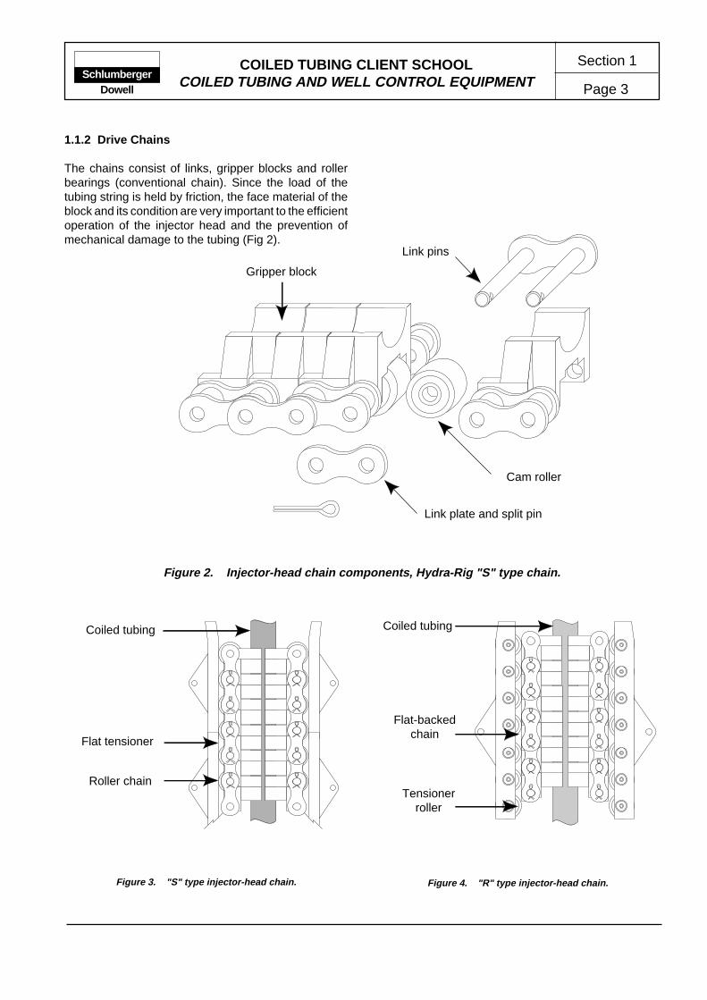
1.1.2 Drive Chains
The chains consist of links, gripper blocks and rollerbearings (conventional chain). Since the load of thetubing string is held by friction, the face material of theblock and its condition are very important to the efficientoperation of the injector head and the prevention ofmechanical damage to the tubing (Fig 2).
Figure 3. "S" type injector-head chain. Figure 4. "R" type injector-head chain.
Flat-backedchain
Tensionerroller
Coiled tubingCoiled tubing
Flat tensioner
Roller chain
Link pins
Gripper block
Cam roller
Link plate and split pin
Figure 2. Injector-head chain components, Hydra-Rig "S" type chain.

COILED TUBING CLIENT SCHOOLCOILED TUBING AND WELL CONTROL EQUIPMENT
Section 1
Page 4Schlumberger
Dowell
InsideChain-Tension
Cylinders
Lower Sprocket
Chain Drive Sprocket
Chain Tension Bars
Outside Chain TensionSprocket
Cut-away section
Cut-away section
1.1.3 Chain Tensioners
As the tubing is run deeper into a well, the load on theinjector chains increases, requiring an increased forceto the gripper blocks to maintain efficient traction. Thisis achieved by using the applied hydraulic pressure inthe inside chain tensioner system (Fig. 5).
Hydra-Rig offers a choice of chain and tensioner systems(Fig. 3 and 4). The traditional design of gripper block hasintegral rollers and solid bar skates (denoted as the "S"type), an alternative configuration has solid back gripperblocks and a roller system on the skate (denoted as the"R" type).
1.1.4 Gooseneck
The gooseneck, or guide arch, acts as a guide for thetubing, taking it through the angle as the tubing leavesthe reel, to the vertical position as it enters the top of theinjector-head chains. Profiled rollers support the tubingas it is bent over the gooseneck arc.
Figure 5. Inside and outside chain tensioner configuration ("S" system).
1.1.5 Weight Indicator
The weight indicator indicates the tension exerted onthe tubing hanging from the injector head chains. Thetensile load measured is a function of the weight of thetubing hanging in the well, and includes the effect of thewellhead pressure and buoyancy. The weight indicatorwill also let the operator see when the tubing tags orhangs up on an obstruction. Weight indicators mayoperate hydraulically, electronically or as a combinationof both. A recording device must always be incorporatedinto the weight indicator system

COILED TUBING CLIENT SCHOOLCOILED TUBING AND WELL CONTROL EQUIPMENT Page 5
Section 1Schlumberger
Dowell
1.2 COILED TUBING REEL
The CT reel is used to store and transport the tubing. Allof the effort required to run, and retrieve the CT from thewell is provided by the injector head. The tensionbetween the reel and injector is necessary to ensure thesmooth feeding of the injector and proper spooling ontothe tubing reel. The major components of the CT reelinclude the following.
• Reel drum
• Reel drive system
• Levelwind assembly
• Reel swivel and manifold
1.2.1 Reel Drum
The capacity of any reel drum for a given size of tubingmay be calculated using the procedure and formulagiven below. The results are approximate, and theformula assumes ideal spooling of the tubing.
The freeboard is the amount of clearance between theOD of the reel flanges and the OD of the wrapped tubingat maximum capacity (L). The minimum recommendedfreeboard varies with the tubing size.
Minimum Recommended Freeboard
Tubing OD (in.) Freeboard (in.)
1 and 1-1/4 1.51-1/2 and 1-3/4 2.0
2 and 2-3/8 3.02-7/8 and 3-1/2 4.0
Example of Calculating Reel Capacity
Tubing OD = 1.50 in.; therefore, the freeboard is 2.0 in.
A = 22 in. (24-in. drum rim height minus 2-in. freeboard)B = 72 in.C = 72 in.K = 0.116
L = (22 + 72) (22) (72) (0.116)
L = 17,272 ft of 1.5-in. tubing.
B
C
Figure 6. Reel drum capacity.
L = (A + C) (A) (B) (K),
whereL = tubing capacity (ft),A = tubing stack height (in.),B = width between flanges (in.),C = reel drum core diameter (in.), andK = K value for different tubing sizes.
K Values for Different Tubing Sizes
Tubing OD (in.) K Value
1 0.2621-1/4 0.1681-1/2 0.1161-3/4 0.0862 0.0662-3/8 0.0462-7/8 0.0323-1/2 0.021
A
Freeboard
COILED TUBING CLIENT SCHOOLCOILED TUBING AND WELL CONTROL EQUIPMENT
Section 1
Page 6Schlumberger
Dowell
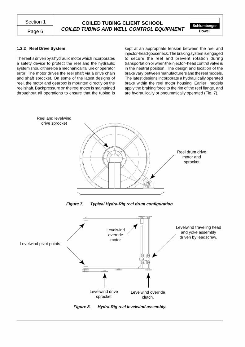
1.2.2 Reel Drive System
The reel is driven by a hydraulic motor which incorporatesa safety device to protect the reel and the hydraulicsystem should there be a mechanical failure or operatorerror. The motor drives the reel shaft via a drive chainand shaft sprocket. On some of the latest designs ofreel, the motor and gearbox is mounted directly on thereel shaft. Backpressure on the reel motor is maintainedthroughout all operations to ensure that the tubing is
kept at an appropriate tension between the reel andinjector-head gooseneck. The braking system is engagedto secure the reel and prevent rotation duringtransportation or when the injector–head control valve isin the neutral position. The design and location of thebrake vary between manufacturers and the reel models.The latest designs incorporate a hydraulically operatedbrake within the reel motor housing. Earlier modelsapply the braking force to the rim of the reel flange, andare hydraulically or pneumatically operated (Fig. 7).
Figure 8. Hydra-Rig reel levelwind assembly.
Reel and levelwinddrive sprocket
Figure 7. Typical Hydra-Rig reel drum configuration.
Reel drum drivemotor andsprocket
Levelwind pivot points
Levelwindoverridemotor
Levelwind traveling headand yoke assemblydriven by leadscrew.
Levelwind drivesprocket
Levelwind overrideclutch.
COILED TUBING CLIENT SCHOOLCOILED TUBING AND WELL CONTROL EQUIPMENT Page 7
Section 1Schlumberger
Dowell
1.2.3 Levelwind Assembly
To minimize the strain and possibility of mechanicaldamage to the tubing, it is important to ensure that thetubing is spooled evenly onto the reel. The levelwindassembly is designed to automatically spool the tubingon and off the reel, though it incorporates a manualoverride facility allowing the operator to correct or preventimproper spooling. The height of the levelwind isadjustable, hydraulically or manually, to match the angleof the tubing between the reel and gooseneck (Fig. 8).
The levelwind also provides a convenient mountingposition for a depth counter or encoder and tubingmonitoring equipment. In addition, equipment requiredto apply CT lubrication or corrosion inhibitor is alsomounted on the levelwind assembly.
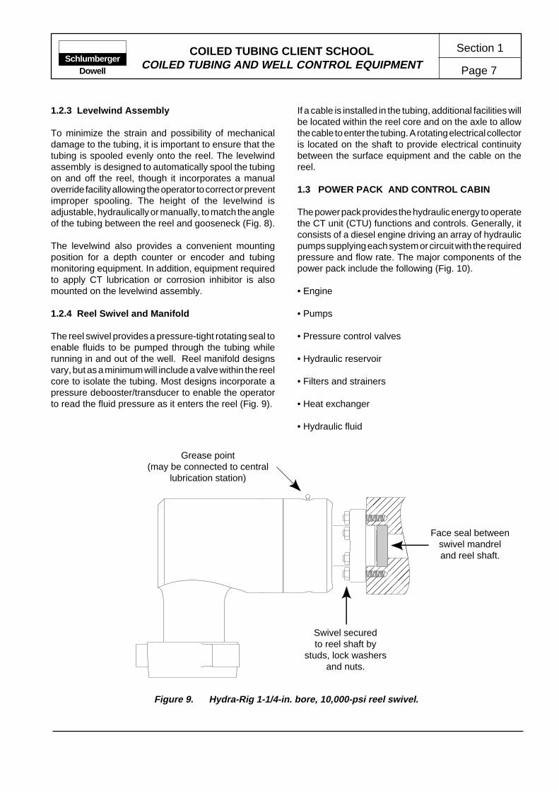
1.2.4 Reel Swivel and Manifold
The reel swivel provides a pressure-tight rotating seal toenable fluids to be pumped through the tubing whilerunning in and out of the well. Reel manifold designsvary, but as a minimum will include a valve within the reelcore to isolate the tubing. Most designs incorporate apressure debooster/transducer to enable the operatorto read the fluid pressure as it enters the reel (Fig. 9).
If a cable is installed in the tubing, additional facilities willbe located within the reel core and on the axle to allowthe cable to enter the tubing. A rotating electrical collectoris located on the shaft to provide electrical continuitybetween the surface equipment and the cable on thereel.
1.3 POWER PACK AND CONTROL CABIN
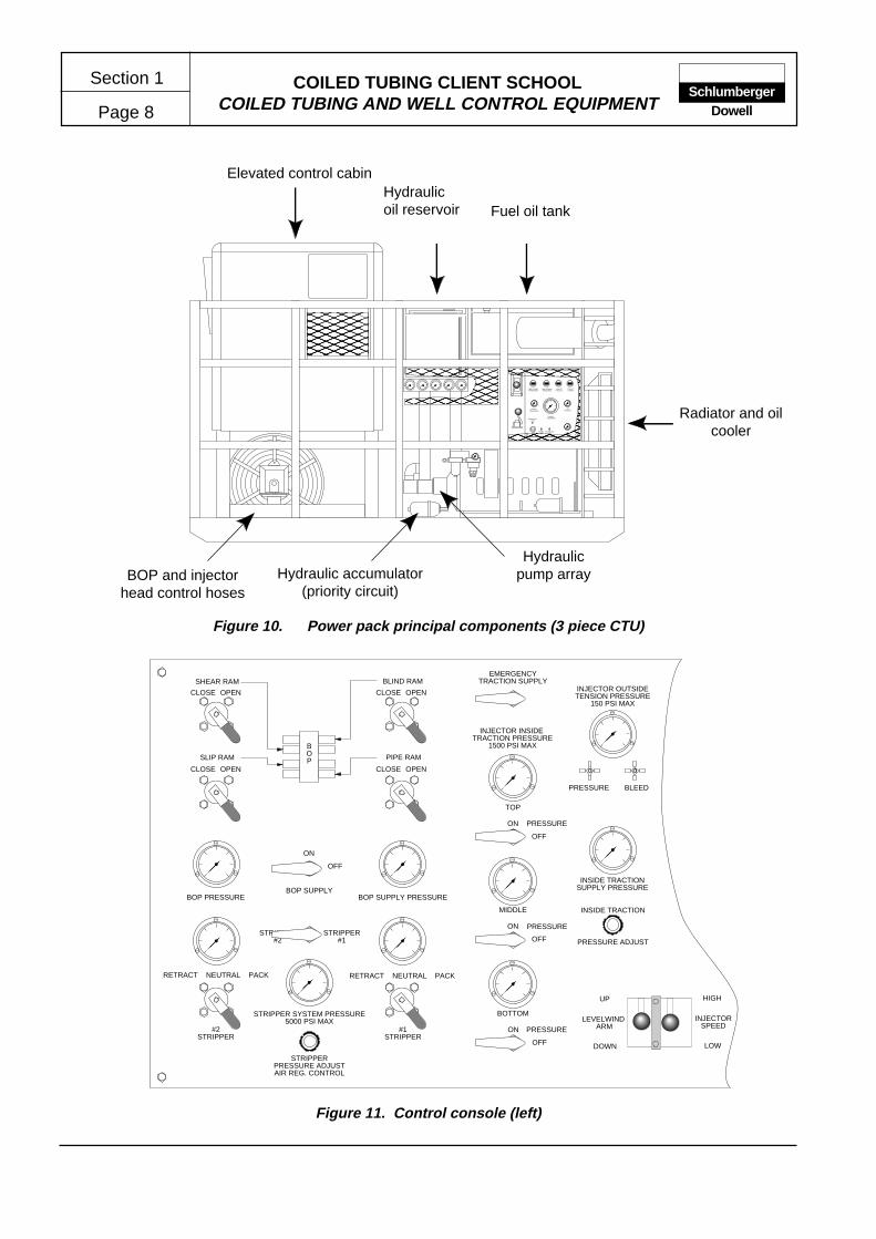
The power pack provides the hydraulic energy to operatethe CT unit (CTU) functions and controls. Generally, itconsists of a diesel engine driving an array of hydraulicpumps supplying each system or circuit with the requiredpressure and flow rate. The major components of thepower pack include the following (Fig. 10).
• Engine
• Pumps
• Pressure control valves
• Hydraulic reservoir
• Filters and strainers
• Heat exchanger
• Hydraulic fluid
Figure 9. Hydra-Rig 1-1/4-in. bore, 10,000-psi reel swivel.
Grease point(may be connected to central
lubrication station)
��
����
�����
Swivel securedto reel shaft by
studs, lock washersand nuts.
Face seal betweenswivel mandreland reel shaft.
COILED TUBING CLIENT SCHOOLCOILED TUBING AND WELL CONTROL EQUIPMENT
Section 1
Page 8Schlumberger
Dowell
Figure 11. Control console (left)
High CoolantTemperature
High ExhaustTemperature
Low OilPressure
Loss of Coolant
Coolant Temperature
OilPressure
Engine Tachometer
AirPressure
Permissive start
EngineKill
EmergencyKill
Start
������
������������
������
Fuel oil tankHydraulicoil reservoir
Elevated control cabin
Radiator and oilcooler
Hydraulicpump arrayHydraulic accumulator
(priority circuit)
Figure 10. Power pack principal components (3 piece CTU)
BOP and injectorhead control hoses
LEVELWIND ARM
UP
DOWN
EMERGENCYTRACTION SUPPLY
INJECTOR INSIDE TRACTION PRESSURE
1500 PSI MAX
TOP
ON
OFF
ON
OFF
ON
OFF
MIDDLE
BOTTOM
INSIDE TRACTION
PRESSURE ADJUST
INSIDE TRACTIONSUPPLY PRESSURE
BLEEDPRESSURE
INJECTOR OUTSIDETENSION PRESSURE
150 PSI MAX
PRESSURE
PRESSURE
PRESSURE
STRIPPER#2
STRIPPER#1
RETRACT NEUTRAL PACKRETRACT NEUTRAL PACK
STRIPPER SYSTEM PRESSURE5000 PSI MAX
STRIPPERPRESSURE ADJUSTAIR REG. CONTROL
#2STRIPPER
#1STRIPPER
BOP SUPPLYBOP PRESSURE BOP SUPPLY PRESSURE
ON
OFF
CLOSE OPEN CLOSE OPEN
CLOSE OPEN CLOSE OPEN
BLIND RAM
PIPE RAM
SHEAR RAM
SLIP RAM
BOP
HIGH
LOW
INJECTORSPEED
COILED TUBING CLIENT SCHOOLCOILED TUBING AND WELL CONTROL EQUIPMENT Page 9
Section 1Schlumberger
Dowell
1.3.1 Engine
The engine of the power pack is generally a dedicatedunit, although on some truck-mounted units the truckengine is used. A variety of engine protection systemsand, if necessary, a complete Zone II protection packagemay be fitted to allow the unit to operate in the environ-ment in which it is required.
1.3.2 Hydraulic Pumps
There are many types and models of hydraulic pumps.The type of pump generally fitted to CTU power packsis the balanced vane type of either single-, or two-stageconstruction.
1.3.3 Pressure Control Valves
Pressure control valves perform functions such as limitingthe maximum system pressure or regulating the reducedpressure in certain portions of a circuit. A relief valve isfound in every circuit. Its purpose is to limit the pressurein a system to a preset maximum by diverting some orall of the flow to the hydraulic fluid reservoir.
1.3.4 Hydraulic Reservoir
The hydraulic reservoir stores the fluid, allows it to cool,allows any entrained air to be released and permits dirtto settle out of the fluid.
1.3.5 Filters and Strainers
The fluid in the hydraulic system is kept clean principallythrough the use of filters and strainers.Generally, strain-ers are fitted to the suction side of the system, e.g., onthe bottom of the reservoir on the suction line. However,filters may be fitted anywhere in the system, providedthe filter and its housing are rated at the appropriatepressure.
1.3.6 Heat Exchangers
The generation of excess heat is a common problem inhydraulic systems. The heat exchangers are principallydesigned to cool the fluid; however, in some environ-ments, it may be necessary to heat the fluid, e.g., wherehigh-viscosity oils have to be warmed to reduce theviscosity in cold climates. The exchanger may useforced air as a coolant or, more commonly, water will becirculated through the exchanger to cool (or heat) thefluid.
Figure 12. Control console (right)
REEL BRAKE
OFF
REEL PRESSURE
REEL PRESSURE ADJUST
REEL CONTROLLEVELWINDOVERRIDE
INSIDE TRACTIONPRESSURE DRAIN
CLOSE OPEN
INJECTORMOTOR PRESSURE
INJECTOR MOTOR PRESSURE ADJUST
INJECTORCONTROL
INJECTOR DIRECTIONALCONTROL VALVEPILOT PRESSURE
PRIORITY PRESSURE2,000 PSI MAX
IN
OUT
ON
OFF
ON
OFF
AIP SUPPLYPRESSURE
30 GPMPUMP
60 GPMPUMP
THROTTLE
ENGINESTOP
EMERGENCYSTOP
AIR HORN
INJECTOR CHAINLUBRICATION
REEL TUBINGLUBRICATION
WELLHEAD PRESSURECIRCULATING PRESSURE
TUBING WEIGHT INDICATOR
SchlumbergerDowell

COILED TUBING CLIENT SCHOOLCOILED TUBING AND WELL CONTROL EQUIPMENT
Section 1
Page 10Schlumberger
Dowell
1.3.7 Hydraulic Fluid
The hydraulic fluid has four primary functions: transmitpower, lubricate moving parts, seal clearances betweenparts, cool components and dissipate heat.
The exact type of hydraulic fluid used in Dowell equipmentmay be determined by local availability and environ-mental conditions. The quality requirements of fluids arewell defined; as a result, a list of recommended fluidshas been compiled for use in Dowell equipment, andshould be followed wherever possible.
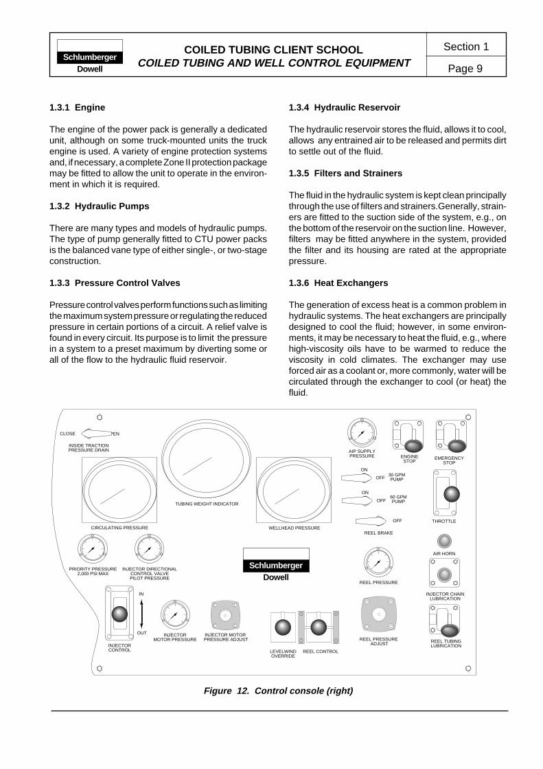
1.3.8 Control Cabin
Depending on the configuration of the CTU, the controlcab may be contained on a separate skid, be incorporatedwith the power-pack skid or be permanently truckmounted.
The control cab will contain all necessary controls andinstruments to allow the CT operation to be run from onecontrol station (Fig. 11 and 12). In some instances,controls and instruments for associated services (e.g.,pumping) are also located in the CTU control cab.Manual pumps for standby or emergency use on essentialhydraulic functions are also located in the control cab.These will include manual or air-driven pumps to energizethe BOP, stripper and skate tension circuits so that wellsecurity can be maintained in the event of a majorequipment failure.
Only qualified personnel are authorized to operate andperform maintenance on the CTU and ancillaryequipment.
2.0 PRESSURE CONTROL EQUIPMENT
2.1 Stripper
The stripper is designed to provide a pressure-tight sealor packoff around the coiled tubing as it is being run (orstripped) in and out of a well with surface pressure. Theseal is achieved by energizing the stripper packer whichforces the inserts to seal against the tubing. The ener-gized force is applied hydraulically and is controlledfrom the operator control cab. Since the packer insertsare consumable and may need to be changed during anoperation, the design of the stripper components allowsthe replacement of inserts while the equipment is riggedup and the tubing is in place. The stripper is flange-mounted to the injector head and when rigged upsupports most of the injector head weight. Figure 13. Well control equipment rig-up.
The side-door stripper is designed to permit easieraccess to the stripper packing arrangement. Conven-tional stripper systems require the packing to be re-moved from the top of the stripper assembly within theinjector-head frame (Fig. 14). Side-door strippers allowthe packing arrangement to be removed below theinjector head. This simplifies the removal and replace-ment of the packing arrangement while the tubing is inplace (Fig. 15).
The side-door stripper has several operational advan-tages over conventional stripper systems:
PrimaryWell ContolEquipment
SecondaryWell ContolEquipment
TertiaryWell ContolEquipment
Gooseneck
Injector Head
Stripper
Quad BOP
Riser
Shear/Seal BOP
Swab Valve
Christmas Tree

COILED TUBING CLIENT SCHOOLCOILED TUBING AND WELL CONTROL EQUIPMENT Page 11
Section 1Schlumberger
Dowell
• The stripper assembly can be mounted closer to theinjector-head chains since there is no longer a require-ment to access the stripper from above.
• The packing arrangement is more accessible, there-fore inspection and replacement are easier and safer.
• The extended guides and bushings improve centrali-zation of the CT, thereby reducing packer wear.
In some instances of extreme well conditions, or ifrequired by the operating company, a dual or tandemstripper assembly can be used.
2.2 Quad and Combi BOPs
The BOPs most commonly used within Dowell areTexas Oil Tools 10,000-psi Working Pressure, H
2S
Resistant Quad or Combi BOPs. They are hydraulicallyoperated from the control cabin using the BOP hydrauliccircuit and accumulator. The accumulator provides areserve of hydraulic energy to enable the BOP to beoperated (for a limited number of functions) following anengine shutdown or circuit failure.
A variety of special BOPs are also used as tertiarypressure barriers, generally providing shear/sealcapabilitties for added safety during offshore operations.
Quad BOPs comprise the following components (Fig.16).
• Blind rams
• Shear rams
• Slip rams
• Pipe rams
• Equalizing valves
• Top and bottom connections
• Side port and pressure port
�������
�
������ ��
����� ����
�
�
�
�
�
�
�
��
���
�
�
��
��
����
����
�
���
����
�
�
�
�
����
��
�
���
�
�
���
�
�
���
����
��
���
�
�����
Packing arrangement
Upper guides
Retract port
Pack port
Pack port
Upper guides
Retract port
Packing arrangement
Figure 14. Conventional stripper assembly. Figure 15. Side-door stripper assembly.
COILED TUBING CLIENT SCHOOLCOILED TUBING AND WELL CONTROL EQUIPMENT
Section 1
Page 12Schlumberger
Dowell
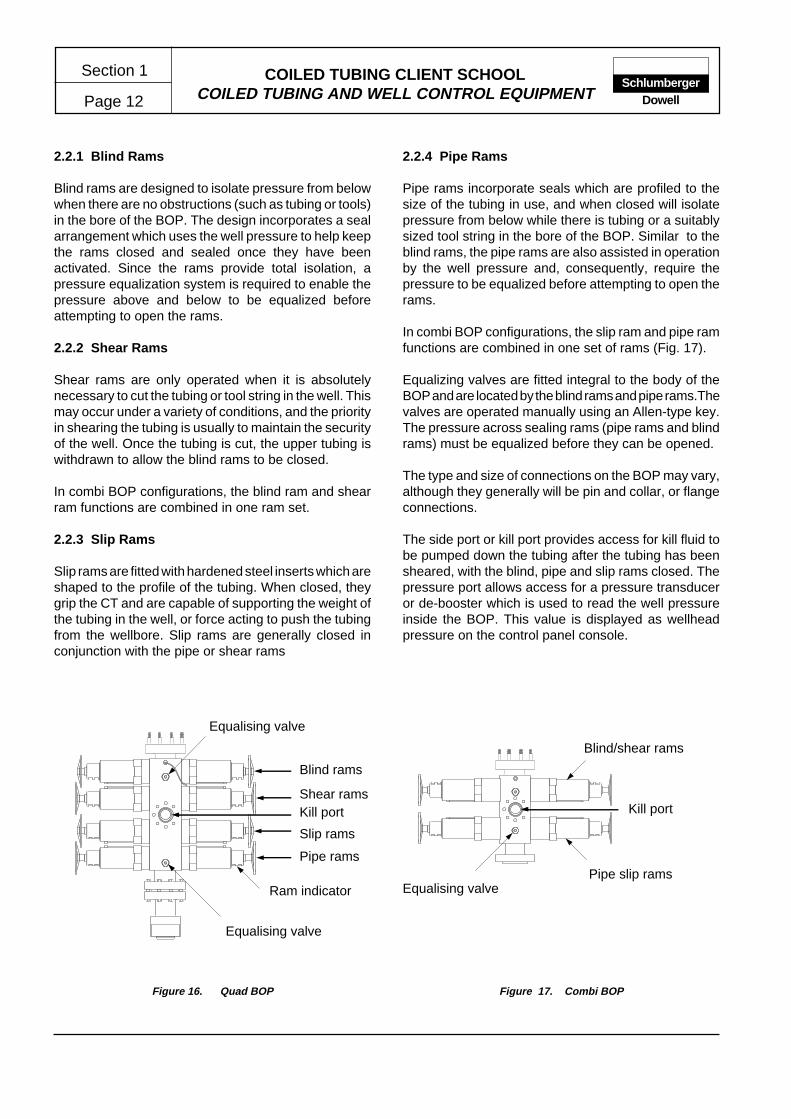
2.2.1 Blind Rams
Blind rams are designed to isolate pressure from belowwhen there are no obstructions (such as tubing or tools)in the bore of the BOP. The design incorporates a sealarrangement which uses the well pressure to help keepthe rams closed and sealed once they have beenactivated. Since the rams provide total isolation, apressure equalization system is required to enable thepressure above and below to be equalized beforeattempting to open the rams.
2.2.2 Shear Rams
Shear rams are only operated when it is absolutelynecessary to cut the tubing or tool string in the well. Thismay occur under a variety of conditions, and the priorityin shearing the tubing is usually to maintain the securityof the well. Once the tubing is cut, the upper tubing iswithdrawn to allow the blind rams to be closed.
In combi BOP configurations, the blind ram and shearram functions are combined in one ram set.
2.2.3 Slip Rams
Slip rams are fitted with hardened steel inserts which areshaped to the profile of the tubing. When closed, theygrip the CT and are capable of supporting the weight ofthe tubing in the well, or force acting to push the tubingfrom the wellbore. Slip rams are generally closed inconjunction with the pipe or shear rams
2.2.4 Pipe Rams
Pipe rams incorporate seals which are profiled to thesize of the tubing in use, and when closed will isolatepressure from below while there is tubing or a suitablysized tool string in the bore of the BOP. Similar to theblind rams, the pipe rams are also assisted in operationby the well pressure and, consequently, require thepressure to be equalized before attempting to open therams.
In combi BOP configurations, the slip ram and pipe ramfunctions are combined in one set of rams (Fig. 17).
Equalizing valves are fitted integral to the body of theBOP and are located by the blind rams and pipe rams.Thevalves are operated manually using an Allen-type key.The pressure across sealing rams (pipe rams and blindrams) must be equalized before they can be opened.
The type and size of connections on the BOP may vary,although they generally will be pin and collar, or flangeconnections.
The side port or kill port provides access for kill fluid tobe pumped down the tubing after the tubing has beensheared, with the blind, pipe and slip rams closed. Thepressure port allows access for a pressure transduceror de-booster which is used to read the well pressureinside the BOP. This value is displayed as wellheadpressure on the control panel console.
Equalising valve
Blind rams
Shear ramsKill port
Slip rams
Pipe rams
Ram indicator
Equalising valve
Blind/shear rams
Pipe slip rams
Kill port
Equalising valve
Figure 17. Combi BOPFigure 16. Quad BOP

Section 2
Page 1COILED TUBING CLIENT SCHOOL MANUAL
DOWNHOLE TOOLS AND EQUIPMENT
Introduction ............................................... 12.1 Standard Thread ....................................... 22.2 Coiled Tubing Connectors ........................ 32.3 Coiled Tubing Check Valves ..................... 42.4 Nozzles and Shoes ................................... 5
ContentsPageContents Page
2.5 Release Joints .......................................... 62.6 Accelerators .............................................. 72.7 Jars ....................................................... 82.8 Overshots .................................................. 92.9 Spears ....................................................... 10
Introduction
Downhole tools of some description are used on almostall coiled tubing operations. Most tools currently usedcan be categorized as follows.
• Primary tools – Coiled tubing connectors and checkvalves are included in this category, i.e., tools whichmay be considered essential for all operations.
• Support tools – This category includes tools such asa release joint and jar, i.e., tools which enhance orsupport the toolstring function, or provide a contingencyrelease function.
• Functional tools – These are tools selected on thebasis of their ability to to perform the intended operation.
The designation STIFFLINE* Services is given to CTservices conducted by Dowell that are generallyconducted using nonelectric wireline tool strings. Suchservices may be categorized as follows.
• Conveying retrievable flow control tools - A widevariety of plugs and flow control devices are commonlyused to selectively control production. The plugs, orlocks, may be located in specific landing nipples,tubing joints or on the tubing wall.
• Operating fixed completion equipment - This principallyinvolves the operation (opening and closing) of slidingsleeves, or circulation devices located in the productiontubing or uncemented production liner.
• Conveying gauges or monitoring equipment - Gaugesand sampling or monitoring equipment can be conveyedby wireline or CT, and if necessary secured in a tubingnipple or similar locating device.
• Wellbore servicing - A variety of well service operationsare commonly performed, generally as preparatorywork before performing other services e.g., tubingdrifting, depth (fill) check, paraffin removal.
• Fishing - Coiled tubing fishing operations can providea rapid and economic solution to a variety of light- tomedium-weight fishing problems.
The operational features of CT conveyed tools andtechniques offers several advantages over conventionalwireline methods.
• Coiled tubing is considerably stronger than slickline orbraided line allowing the application of greater forcesand lifting capacity.
• The rigidity of CT allows access to highly deviated orhorizontal wellbores.
• Fluids circulated through the CT can be used toimprove access to the fish or wellbore equipment to beengaged.
• Fluids pumped through the CT can also be used topower specialized tools.
SchlumbergerDowell
* Mark of Schlumberger

COILED TUBING CLIENT SCHOOLDOWNHOLE TOOLS AND EQUIPMENT
Section 2
Page 2Schlumberger
Dowell
Stub acme threads
O-ring seal bore
Stub acme threads
O-ring seal
����
�����
����
����
����
�����
�����
�����
����
CT Size(in.)
Make-Up Length
(in.)
Minimum OD(in.)
MaximumID
(in.)
Max Working Pressure
(psi)
Max Operating Temperature
(°F)
Max Static Torque(ft-lbf)
Max Tensile Load(lbf)
1-1/41-1/21-3/4
2.8501.6902.1252.563
0.9371.250 5000 350
15002500
Exceeds tubing value
2.1 STANDARD THREADS
Schlumberger Dowell has designed three standardthread specifications for use in coiled tubing applica-tions. The purpose of these thread specifications is toprovide a uniform worldwide standard so all downholetools successfully make up on location. The standardthreaded connections are available in the followingsizes:
• 1-1/4-in. CT standard thread, designated as a nominal1.500-in.-10 Stub Acme 2G
• 1-1/2 in. CT standard thread, designated as a nominal1.812-in.-10 Stub Acme 2G
• 1-3/4 in. CT standard thread, designated as a nominal2.000 in. -10 Stub Acme 2G
The standard thread connections are also available ina non-rotating configuration. This connection is de-signed for use when there is difficulty making up theconnection or where the tools cannot be rotated.
The material selected for tool and thread constructionshould be chosen to meet the requirements of the toolsapplication. However, a material with a yield stress ofless than 75,000 psi should not be used for the standardthread connections. The benefits of the Dowell stan-dard thread design include the following:
• The threads are protected from treatment fluids bydual O-ring seals.
• During make-up, the threads engage before the O-rings, reducing the likelihood of damaging the sealduring assembly.
Specifications

COILED TUBING CLIENT SCHOOLDOWNHOLE TOOLS AND EQUIPMENT Page 3
Section 2Schlumberger
Dowell
Coiled tubing
Setscrew
O-ring
Standard thread
O-ring
Crimped tubing
Standard thread
Coiled tubing
�@�À�@�À�@�À�@�À��@�À�@�À�@�À�@�À�
2.2 COILED TUBING CONNECTORS
Coiled tubing connectors connect various downholetools to the end of the CT. Connectors are commerciallyavailable in a wide range of designs and sizes. However,three types of connectors are recommended for usewithin Schlumberger Dowell, the Dowell GrappleConnector, the Setscrew/Dimple Connector and theRoll-On Connector. Selecting the appropriate connectoris generally dependent on the application and operatorpreference.
Setscrew/dimple connector
The Setscrew Connector is attached to the CT by set-screws engaging in preformed dimples. A dimpling toolis used to place the dimples in the same pattern asformed by the screws on the connector. The setscrewconnector attaches to the outside diameter of the CT,and therefore, interferes less with the internal flow pathof the tubing.
Roll-on connector
The roll-on connector attaches to the internal diameterof the CT and is held in place by crimping the CT arounda connector profile with a special crimping tool. However,the roll-on connector poses a significant obstruction tofluids, darts or balls pumped through the CT. In specialapplications where an extremely slim bottomholeassembly is required, and where low torque and tensilestrength values are required, the roll-on connector maybe considered a practical alternative to the grapple andsetscrew connector.
ConnectorType
CT Size(in.)
Typical OD(in.)
Typical ID
(in.)
Max Working Pressure
(psi)
Max Operating Temperature
(°F)
Max Tensile Load(lbf)
TorqueTolerence
(ft-lbf)
Setscrew1-1/41-1/21-3/4
1.7502.0002.250
0.7501.0601.125
5000 300 25,000Exceeds
tubing value
Roll-On1-1/41-1/21-3/4
1.2501.5001.750
0.6250.6251.000
5000 300 21,000 50
Specifications

COILED TUBING CLIENT SCHOOLDOWNHOLE TOOLS AND EQUIPMENT
Section 2
Page 4Schlumberger
Dowell
2.3 COILED TUBING CHECK VALVES
The check valve is generally attached to the coiledtubing connector at the end of the CT string. Bypreventing the flow of well fluids into the CT, wellsecurity is maintained in the event of failure or damageto the tubing at surface. Check valves should be part ofevery CT bottomhole assembly and should only beomitted when the application precludes its use (e.g.,where it is desired to reverse circulate through the CT).In most cases it is recommended that tandem checkvalves be fitted to provide some redundancy of operation.
Flapper check valves
Flapper check valves are, by necessity, becoming morecommonly used. The fullbore (or near fullbore) openingpermits the use of more complex CT tools, fluids andoperating techniques by allowing balls, darts and plugsto pass through to the toolstring from the CT withoutrestriction. Most flapper check valves are of similardesign, although some may incorporate a cartridgevalve assembly for ease of maintenance.
Ball and seat check valves
The ball and seat check valve has been predominantlyused on conventional CT applications because of itssimple construction and ease of maintenance. However,this design has several limitations including restrictedflow area and bore obstruction. These limitations requireusing an alternative when fullbore opening or unrestrictedflow area is required.
Check ValveType
Typical Length
(in.)
Typical OD(in.)
Typical ID
(in.)
Max Working Pressure
(psi)
Max Operating Temperature
(°F)
Max Tensile Load(lbf)
Ball and Seat
6 to 121.6882.1252.563
N/A 5000 300Exceeds
tubing value
Flapper 6 to 121.6882.1252.563
0.6251.0001.300
5000 300Exceeds
tubing value
Specifications
Top connection
SeatBall
Bottom connection
Top connection
Flapper
Bottom connection
Seat
Flappercheck valveassembly
Ball andseat check
valveassembly

COILED TUBING CLIENT SCHOOLDOWNHOLE TOOLS AND EQUIPMENT Page 5
Section 2Schlumberger
Dowell
2.4 NOZZLES AND JETTING SUBS
Nozzles and jetting subs for use on coiled tubing formthe downhole “end” of the CT bottomhole assembly.These nozzles and subs are generally of simple designand construction and are often locally manufactured.The required jetting action generally determines theposition and size of the nozzle ports. In general, thesetools will fall into two categories.
Circulating subs
Nozzles used on operations where fluids are to becirculated without a jetting action require a large portarea. This port area may be composed of several smallports to increase turblence, or a few large ports; thecriteria being that there is relatively little pressure dropacross the nozzle.
Jetting subs
Nozzles used on operations that require jetting actionwill have a relatively small port area, usually composedof several small ports. The efficiency of a jetting nozzleis largely dependent on the fluid velocity through theport. The largest constraints on the jetting nozzle designare the limits of the flow rate and pressure available atthe nozzle. These limits are a result of the relatively largefriction pressure induced within the CT string.
The position, shape and direction of the jet ports affectthe jetting action of the nozzle, and in most cases, aredetermined by the intended application.
Combination nozzles are often used to perform specialoperations. The various functions of combination nozzlescan be accomplished with a ball or sleeve mechanismwithin the nozzle assembly, which is activated to blockcertain ports. Simple versions are activated by droppinga ball through the CT work string.
�@�À�@�À�@�À�@�À�
Single Large-Diameter Port
Multiple Small-Diameter Ports
Muleshoe AngledJet Nozzle
COILED TUBING CLIENT SCHOOLDOWNHOLE TOOLS AND EQUIPMENT
Section 2
Page 6Schlumberger
Dowell
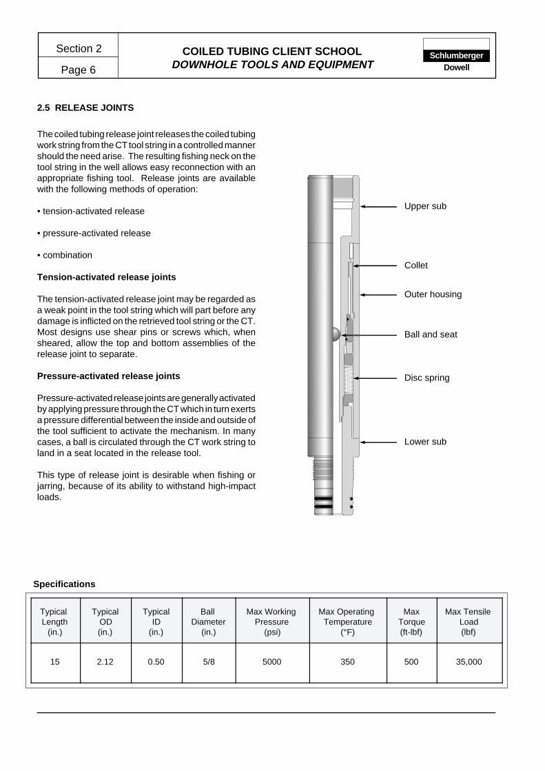
2.5 RELEASE JOINTS
The coiled tubing release joint releases the coiled tubingwork string from the CT tool string in a controlled mannershould the need arise. The resulting fishing neck on thetool string in the well allows easy reconnection with anappropriate fishing tool. Release joints are availablewith the following methods of operation:
• tension-activated release
• pressure-activated release
• combination
Tension-activated release joints
The tension-activated release joint may be regarded asa weak point in the tool string which will part before anydamage is inflicted on the retrieved tool string or the CT.Most designs use shear pins or screws which, whensheared, allow the top and bottom assemblies of therelease joint to separate.
Pressure-activated release joints
Pressure-activated release joints are generally activatedby applying pressure through the CT which in turn exertsa pressure differential between the inside and outside ofthe tool sufficient to activate the mechanism. In manycases, a ball is circulated through the CT work string toland in a seat located in the release tool.
This type of release joint is desirable when fishing orjarring, because of its ability to withstand high-impactloads.
Typical Length
(in.)
TypicalOD(in.)
TypicalID
(in.)
Ball Diameter
(in.)
Max Working Pressure
(psi)
Max Operating Temperature
(°F)
MaxTorque(ft-lbf)
Max Tensile Load(lbf)
15 2.12 0.50 5/8 5000 350 500 35,000
Specifications
Collet
Outer housing
Ball and seat
Disc spring
Lower sub
Upper sub
��� @@@ ��� ÀÀÀ ��� @@@ ��� ÀÀÀ ��� @@@ ��� ÀÀÀ ��� @@@ ��� ÀÀÀ �����@@��ÀÀ��@@��ÀÀ��@@��ÀÀ��@@��ÀÀ��
��@A��ÀÁ��@A��ÀÁ��@A��ÀÁ��@A��ÀÁ��
COILED TUBING CLIENT SCHOOLDOWNHOLE TOOLS AND EQUIPMENT Page 7
Section 2Schlumberger
Dowell
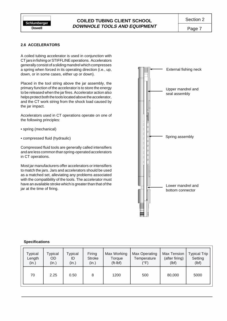
2.6 ACCELERATORS
A coiled tubing accelerator is used in conjunction withCT jars in fishing or STIFFLINE operations. Acceleratorsgenerally consist of a sliding mandrel which compressesa spring when forced in its operating direction (i.e., up,down, or in some cases, either up or down).
Placed in the tool string above the jar assembly, theprimary function of the accelerator is to store the energyto be released when the jar fires. Accelerator action alsohelps protect both the tools located above the accelerator,and the CT work string from the shock load caused bythe jar impact.
Accelerators used in CT operations operate on one ofthe following principles:
• spring (mechanical)
• compressed fluid (hydraulic)
Compressed fluid tools are generally called intensifiersand are less common than spring-operated acceleratorsin CT operations.
Most jar manufacturers offer accelerators or intensifiersto match the jars. Jars and accelerators should be usedas a matched set, alleviating any problems associatedwith the compatibility of the tools. The accelerator musthave an available stroke which is greater than that of thejar at the time of firing.
Typical Length
(in.)
Typical OD(in.)
Typical ID
(in.)
Firing Stroke(in.)
Max Working Torque(ft-lbf)
Max Operating Temperature
(°F)
Max Tension (after firing)
(lbf)
Typical TripSetting
(lbf)
70 2.25 0.50 8 1200 500 80,000 5000
Specifications
External fishing neck
Lower mandrel andbottom connector
Spring assembly
Upper mandrel andseal assembly

COILED TUBING CLIENT SCHOOLDOWNHOLE TOOLS AND EQUIPMENT
Section 2
Page 8Schlumberger
Dowell
Firing mechanism
Adjusting mechanism
Mandrel
�@�À�@�À�@�À�@�À�
Spring assembly
Hammer
Anvil
Splined mandrel
2.7 JARS
A jar may be described as a device which delivers asudden shock (up or down) to the tool string. In coiledtubing applications, jar assemblies generally include asliding mandrel arrangement which allows the brief andsudden acceleration of the tool string above the jar.Travel of the mandrel is limited by a stop (hammer)which strikes a corresponding stop on the outer mandrel(anvil).
Most jars release (also called a trip, fire, hit or lick) in onedirection only. However, some designs feature theability to jar up and down without resetting the tool.
An accelerator (detailed elsewhere) must be included inany CT bottomhole assembly in which a jar is fitted. Theaccelerator is placed in the tool string above the jarassembly in order to store the energy that will bereleased when the jar fires.
Jars commonly used in CT operations operate on one ofthe following principles:
• mechanical
• hydraulic
• fluid powered (e.g., impact drill).
All three jar types operate on the upstroke; however,only jars operating on the mechanical and fluid-poweredprinciples are capable of downstroke or dual operation.The ability to jar down is an important feature which maybe required on many fishing and STIFFLINE* operations.The release of many overshots, spears and pulling toolsoften requires a downward blow at the tool.
Typical Length
(in.)
Typical OD(in.)
Typical ID
(in.)
Firing Stroke(in.)
Max Working Torque(ft-lbf)
Max Operating Temperature
(°F)
Max Tension (after firing)
(lbf)
Typical TripSetting
(lbf)
70 2.25 0.50 8 1200 500 80,000 5000
Specifications

COILED TUBING CLIENT SCHOOLDOWNHOLE TOOLS AND EQUIPMENT Page 9
Section 2Schlumberger
Dowell
Top connector/fishing neck
Catch spring
Catch/release mechanism
Adjustable stop
Grapple
Bowl
�@�À�@�À�@�À�@�À�
�@�À�@�À�@�À�@�À�
��@@��ÀÀ��@@��ÀÀ��@@��ÀÀ��@@��ÀÀ��
�@�À�@�À�@�À�@�À��@�À�@�À�@�À�@�À�
�@�À�@�À�@�À�@�À�
�@�À�@�À�@�À�@�À��@�À�@�À�@�À�@�À�
��@@��ÀÀ��@@��ÀÀ��@@��ÀÀ��@@��ÀÀ��
2.8 OVERSHOTS
Overshots are commonly used on a wide variety ofcoiled tubing fishing operations. Overshots are designedto engage over the fish to be retrieved, gripping on theOD surface of the fishing neck.
Once latched on the fish, the grip exerted by the overshotgrapple increases as the tool string tension is increased.In the event the fish or tool to be retrieved is immovable,a release mechanism can be activated to retrieve the CTand tool string. This release may be incorporated intothe design of the overshot (releasable overshot) or mayrequire the operation of a separate CT release joint(non-releasable overshot).
It is recommended that only releasable overshots beused in CT applications. Non-releasable overshotsshould be avoided and only run where the implication oftheir use is fully understood.
The design and operation of releasable overshots usedby Dowell, vary slightly among manufacturers. However,the principal features and components are similar andinclude the following:
• A catch/release mechanism, usually controlled by aratchet mechanism, which cycles each time weight isset on the tool.
• A bowl/grapple assembly which should be selectedonly after consideration of the fishing neck profile,overshot reach and completion restrictions.
• A circulation facility which enables the circulation offluid and offers significant advantage over alternativefishing methods.
Typical Length
(in.)
Typical OD(in.)
Typical ID
(in.)
GrappleRange(fishing neck)
(in.)
Max WorkingPressure
(psi)
Max Operating Temperature
(°F)
Max Tensile Load(lbf)
30 2.25 0.50 0.88 to 4.50 5000 350 40,000
Specifications
COILED TUBING CLIENT SCHOOLDOWNHOLE TOOLS AND EQUIPMENT
Section 2
Page 10Schlumberger
Dowell
Top connection/fishing neck
Catch/release mechanism
Catch spring
Adjustable stop
Grapple
Nose cone
�@�À�@�À�@�À�@�À�
�@�À�@�À�@�À�@�À��@�À�@�À�@�À�@�À�
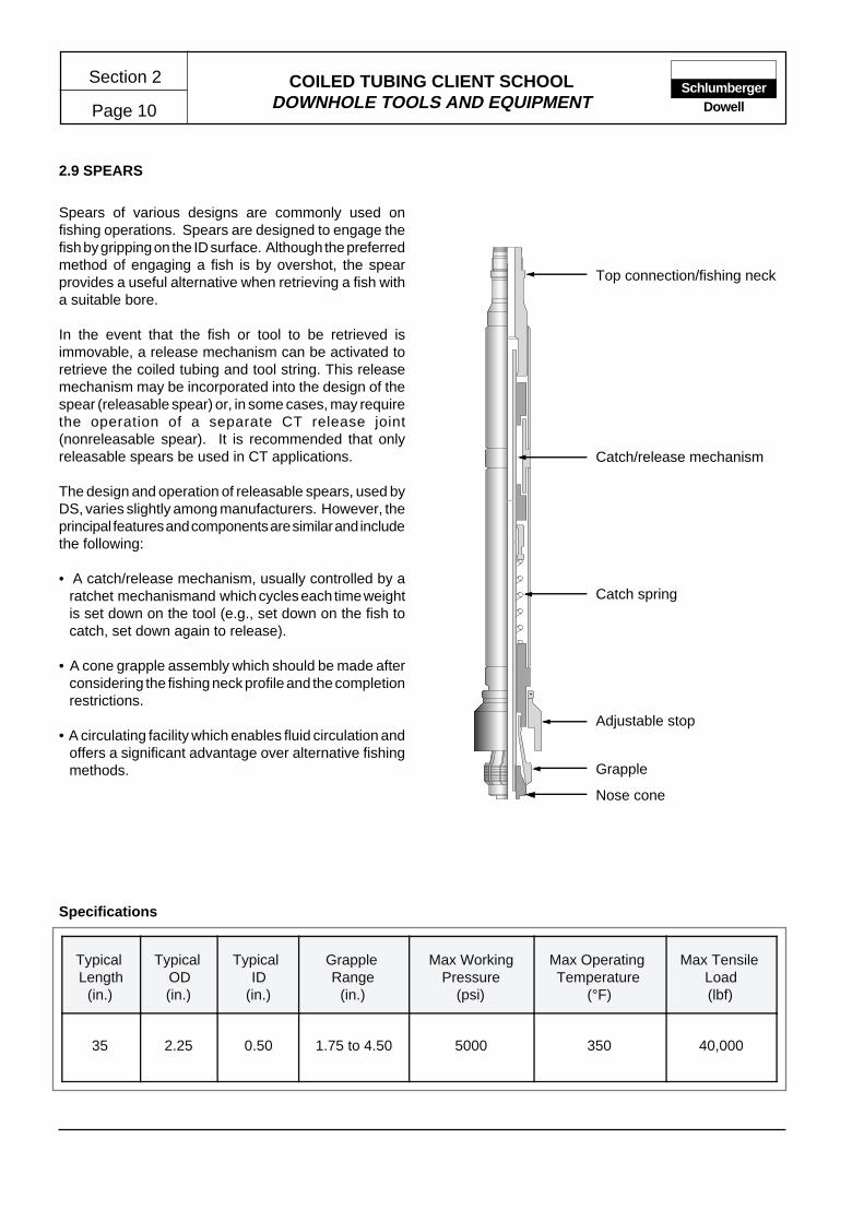
2.9 SPEARS
Spears of various designs are commonly used onfishing operations. Spears are designed to engage thefish by gripping on the ID surface. Although the preferredmethod of engaging a fish is by overshot, the spearprovides a useful alternative when retrieving a fish witha suitable bore.
In the event that the fish or tool to be retrieved isimmovable, a release mechanism can be activated toretrieve the coiled tubing and tool string. This releasemechanism may be incorporated into the design of thespear (releasable spear) or, in some cases, may requirethe operation of a separate CT release joint(nonreleasable spear). It is recommended that onlyreleasable spears be used in CT applications.
The design and operation of releasable spears, used byDS, varies slightly among manufacturers. However, theprincipal features and components are similar and includethe following:
• A catch/release mechanism, usually controlled by aratchet mechanismand which cycles each time weightis set down on the tool (e.g., set down on the fish tocatch, set down again to release).
• A cone grapple assembly which should be made afterconsidering the fishing neck profile and the completionrestrictions.
• A circulating facility which enables fluid circulation andoffers a significant advantage over alternative fishingmethods.
Typical Length
(in.)
Typical OD(in.)
Typical ID
(in.)
Grapple Range
(in.)
Max WorkingPressure
(psi)
Max Operating Temperature
(°F)
Max Tensile Load(lbf)
35 2.25 0.50 1.75 to 4.50 5000 350 40,000
Specifications

Section 3
Page 1COILED TUBING CLIENT SCHOOL MANUAL
COILED TUBING STRING
1 OPERATING LIMITS ................................ 11.1 Pressure and Tension .................... 2
1.1.1 Internal Burst Pressure .......... 31.1.2 External Collapse Pressure ... 31.1.3 Wellhead Pressure ................ 31.1.4 Tension .................................. 3
1.2 Diameter and Ovality ...................... 31.3 Fatigue and Corrosion .................... 51.4 Pumping and Flowing ..................... 6
1.4.1 Pumped Fluids ...................... 61.4.2 Reverse Circulation ............... 61.4.3 Flowing Through CT .............. 6
1.5 Hydrogen Sulfide ............................ 61.5.1 Determining Sour Status ....... 7
2 COILED TUBING FORCES ...................... 72.1 Buoyant Weight .............................. 82.2 Well Profile ..................................... 9
ContentsPageContents Page
1 OPERATING LIMITS
The experience associated with Dowell research anddevelopment efforts has helped create well-defined,recommended operating limits and procedures forcoiled tubing (CT) operations.
This manual section will identify the current Dowellrecommended operating limits, and outline the factorsthat contribute toward them. Most of these factors aredependent on the physical and metallurgicalcharacteristics of the tubing, and on the history of theCT string. However, some of the operating limits givenapply to operating techniques and conditions.
Several of the limits are defined by the use of CoilCADE*computer models and modules. Therefore, anunderstanding of the input requirements of these modelsis essential in the design process of any Dowell CToperation. In addition, correct interpretation of theCoilCADE output plots and tables is required to ensurethe operation is designed and safely executed withinthe prescribed limits.
The limits discussed in this section apply to the followingaspects of CT and CT operations.
• Pressure and tension
• Diameter and ovality
• Fatigue and corrosion
• Pumped or produced fluids
• H2S considerations
Tubing fatigue and reel history data are factors whichmay influence the limitations and applications of particulartubing strings. These effects are cumulative and requirea recording system to accurately monitor the progress ofthe tubing life.
SchlumbergerDowell
2.3 Residual Bend ................................ 92.4 Buckling .......................................... 92.5 Fluid Turbulence ............................. 102.6 Stripper Friction .............................. 102.7 Wellhead Pressure ......................... 112.8 Tubing Reel Back Tension ............. 11
3 COILED TUBING FATIGUE ..................... 113.1 Stress and Strain ............................ 123.2 Stress-Strain Theory ...................... 123.3 Stress-Strain Theory Applied to
Coiled Tubing ................................. 143.3.1 Stress Applied in the Well ..... 143.3.2 Stress Applied at Surface ...... 15
3.4 Fatigue Testing ............................... 163.4.1 Fatigue Testing Results ......... 17
4 REFERENCES ......................................... 19
* Mark of Schlumberger
COILED TUBING CLIENT SCHOOLCOILED TUBING STRING
Section 3
Page 2Schlumberger
Dowell
1.1 Pressure and Tension
The factors which affect the operational limits of a CTstring in any application are often interactive,e.g., thepressure capacity of a CT string can be greatly affectedby the tension to which it is subjected. Therefore, it isessential that all relevant factors are taken into accountwhen determining any operational limits.
The CoilLIMIT* module of the CoilCADE programdetermines the pressure and tension limits that apply toa CT work string in given wellbore conditions. Using theVon Mises incipient yield criteria, the model determinesthe pressure and tension limits at which the CT beginsto yield.
The effect of ovality is considered in the model collapsepressure calculation. In addition, the effect of helicalbuckling within the wellbore tubular is also considered.The limits calculated for a previous job will apply unlessone of the following points apply:
• Acid or corrosive fluids have been pumped sinceprevious limits were calculated.
• Significant corrosion has occurred to the CT.
• The wellbore or tubulars on the intended operation arelarger than those for which the previous limits werecalculated.
• The wellbore conditions of the intended operation aregreater than these for which the previous limits werecalculated.
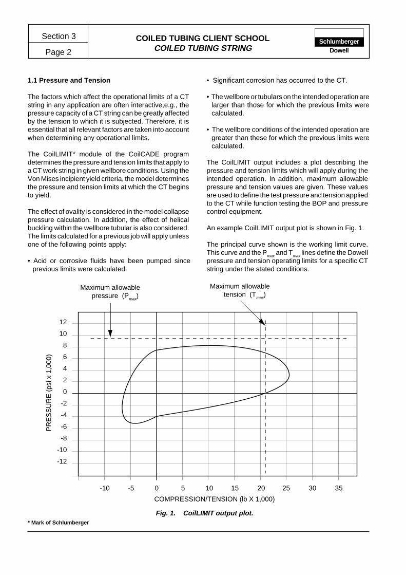
The CoilLIMIT output includes a plot describing thepressure and tension limits which will apply during theintended operation. In addition, maximum allowablepressure and tension values are given. These valuesare used to define the test pressure and tension appliedto the CT while function testing the BOP and pressurecontrol equipment.
An example CoilLIMIT output plot is shown in Fig. 1.
The principal curve shown is the working limit curve.This curve and the Pmax and Tmax lines define the Dowellpressure and tension operating limits for a specific CTstring under the stated conditions.
-10 -5 0 5 10 15 20 25 30 35
-12
-10
-8
-6
-4
-2
0
2
4
6
8
10
12
Maximum allowablepressure (Pmax)
Maximum allowabletension (Tmax)
COMPRESSION/TENSION (lb X 1,000)
PR
ES
SU
RE
(ps
i x 1
,000
)
Fig. 1. CoilLIMIT output plot.* Mark of Schlumberger
COILED TUBING CLIENT SCHOOLCOILED TUBING STRING Page 3
Section 3Schlumberger
Dowell
In the event that CoilLIMIT output data are not available,the following longstanding recommended limits willapply.
1.1.1 Internal Burst Pressure
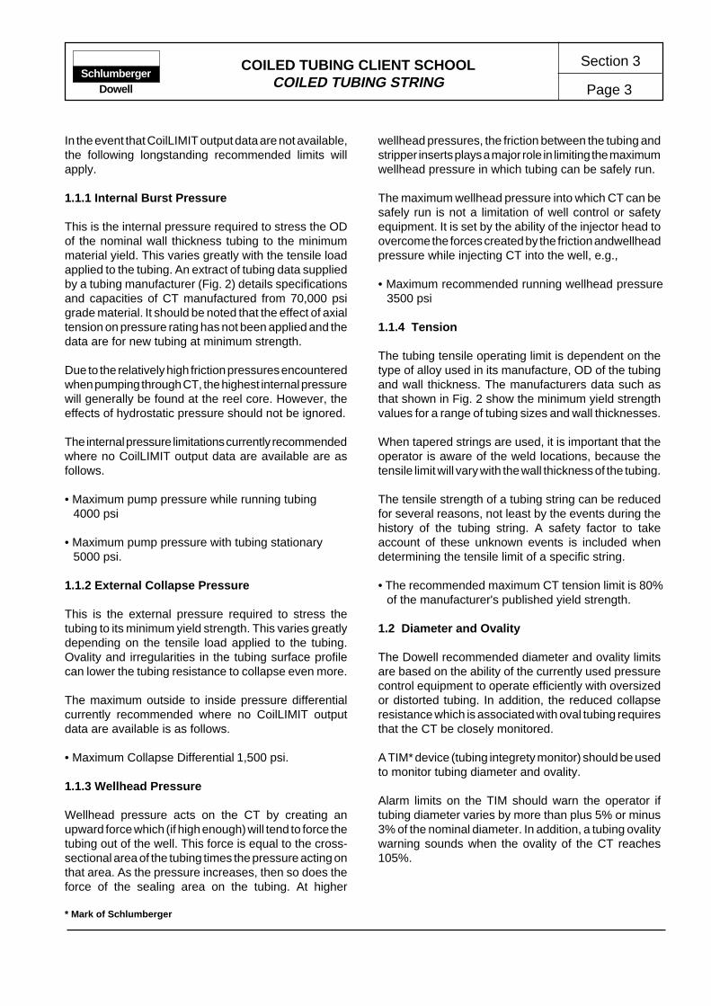
This is the internal pressure required to stress the ODof the nominal wall thickness tubing to the minimummaterial yield. This varies greatly with the tensile loadapplied to the tubing. An extract of tubing data suppliedby a tubing manufacturer (Fig. 2) details specificationsand capacities of CT manufactured from 70,000 psigrade material. It should be noted that the effect of axialtension on pressure rating has not been applied and thedata are for new tubing at minimum strength.
Due to the relatively high friction pressures encounteredwhen pumping through CT, the highest internal pressurewill generally be found at the reel core. However, theeffects of hydrostatic pressure should not be ignored.
The internal pressure limitations currently recommendedwhere no CoilLIMIT output data are available are asfollows.
• Maximum pump pressure while running tubing4000 psi
• Maximum pump pressure with tubing stationary5000 psi.
1.1.2 External Collapse Pressure
This is the external pressure required to stress thetubing to its minimum yield strength. This varies greatlydepending on the tensile load applied to the tubing.Ovality and irregularities in the tubing surface profilecan lower the tubing resistance to collapse even more.
The maximum outside to inside pressure differentialcurrently recommended where no CoilLIMIT outputdata are available is as follows.
• Maximum Collapse Differential 1,500 psi.
1.1.3 Wellhead Pressure
Wellhead pressure acts on the CT by creating anupward force which (if high enough) will tend to force thetubing out of the well. This force is equal to the cross-sectional area of the tubing times the pressure acting onthat area. As the pressure increases, then so does theforce of the sealing area on the tubing. At higher
wellhead pressures, the friction between the tubing andstripper inserts plays a major role in limiting the maximumwellhead pressure in which tubing can be safely run.
The maximum wellhead pressure into which CT can besafely run is not a limitation of well control or safetyequipment. It is set by the ability of the injector head toovercome the forces created by the friction andwellheadpressure while injecting CT into the well, e.g.,
• Maximum recommended running wellhead pressure3500 psi
1.1.4 Tension
The tubing tensile operating limit is dependent on thetype of alloy used in its manufacture, OD of the tubingand wall thickness. The manufacturers data such asthat shown in Fig. 2 show the minimum yield strengthvalues for a range of tubing sizes and wall thicknesses.
When tapered strings are used, it is important that theoperator is aware of the weld locations, because thetensile limit will vary with the wall thickness of the tubing.
The tensile strength of a tubing string can be reducedfor several reasons, not least by the events during thehistory of the tubing string. A safety factor to takeaccount of these unknown events is included whendetermining the tensile limit of a specific string.
• The recommended maximum CT tension limit is 80%of the manufacturer's published yield strength.
1.2 Diameter and Ovality
The Dowell recommended diameter and ovality limitsare based on the ability of the currently used pressurecontrol equipment to operate efficiently with oversizedor distorted tubing. In addition, the reduced collapseresistance which is associated with oval tubing requiresthat the CT be closely monitored.
A TIM* device (tubing integrety monitor) should be usedto monitor tubing diameter and ovality.
Alarm limits on the TIM should warn the operator iftubing diameter varies by more than plus 5% or minus3% of the nominal diameter. In addition, a tubing ovalitywarning sounds when the ovality of the CT reaches105%.
* Mark of Schlumberger

COILED TUBING CLIENT SCHOOLCOILED TUBING STRING
Section 3
Page 4Schlumberger
Dowell
Fig
. 2.
Man
ufac
ture
rs tu
bing
dat
a fo
r 7
0,00
0 ps
i coi
led
tubi
ng w
ork
strin
g m
ater
ial.
0.75
0.06
70.
063
0.61
60.
143
0.29
80.
489
10,0
3110
,748
9,
400
12,
600
10,7
22
5.4
8 0
.369
22.9
50.
547
1.00
0.06
70.
063
0.86
60.
196
0.59
80.
668
13,7
2015
,040
6,
980
11,
440
8,2
60 3
0.60
0.7
2940
.78
0.97
11.
000.
075
0.07
10.
850
0.21
80.
568
0.74
115
,260
17,4
40
7,86
0 1
2,90
0 9
,970
29.
51 0
.703
40.7
80.
971
1.00
0.08
70.
083
0.82
60.
250
0.53
60.
848
17,5
0020
,000
9,
200
15,
100
11,1
20 2
7.84
0.6
6340
.78
0.97
11.
000.
095
0.09
10.
810
0.27
00.
515
0.91
818
,900
21,6
0010
,080
16,
500
12,0
30 2
6.54
0.6
3740
.78
0.97
11.
000.
109
0.10
40.
782
0.30
50.
480
1.03
721
,350
24,4
0011
,530
19,
210
13,6
00 2
4.94
0.5
9440
.78
0.97
1
1.25
0.06
70.
063
1.11
60.
247
0.98
00.
840
17,2
9019
,760
5,5
80
9,02
0 5
,410
50.
21 1
.212
63.7
51.
518
1.25
0.07
50.
071
1.10
00.
277
0.95
00.
941
19,3
9022
,160
6,2
90 1
0,13
0 6
,770
49.
35 1
.175
63.7
51.
518
1.25
0.08
70.
083
1.07
60.
318
0.90
91.
081
22,2
6025
,440
7,3
60 1
1,90
0 8
,810
47.
22 1
.124
63.7
51.
518
1.25
0.09
50.
091
1.06
00.
345
0.88
21.
172
24,1
5027
,600
8,07
0 1
3,05
0 9
,830
45.
82 1
.094
63.7
51.
518
1.25
0.10
20.
097
1.04
60.
368
0.85
91.
251
27,3
4031
,250
9,10
011
,400
10,4
5044
.64
1.06
363
.75
1.51
81.
250.
109
0.10
41.
032
0.39
10.
837
1.32
827
,370
31,2
809,
220
15,
180
11,1
40 4
3.48
1.0
3563
.75
1.51
81.
250.
125
0.11
81.
000
0.44
20.
785
1.50
231
,000
33,2
2510
,000
13,2
0012
,500
40.
80 0
.971
63.7
51.
518
1.25
0.13
40.
128
0.98
20.
470
0.75
71.
597
32,8
8635
,235
10,0
00
15,0
0013
,300
39.
34 0
.936
63.7
51.
518
1.25
0.15
60.
148
0.93
80.
536
0.69
11.
840
37,1
0039
,750
10,0
00
17,4
0015
,200
35.
89 0
.855
63.7
51.
518
1.50
0.09
50.
091
1.31
00.
419
1.34
81.
425
29,3
5033
,540
6,7
2010
,750
7,4
90 7
0.03
1.6
6791
.806
2.18
61.
500.
109
0.10
41.
282
0.47
61.
291
1.61
933
,340
38,1
00 7
,680
12,4
30 9
,430
67.
06 1
.597
91.8
062.
186
1.50
0.12
50.
119
1.25
00.
540
1.22
71.
836
37,8
0043
,200
8,7
9014
,390
10,6
90 6
3.74
1.5
1891
.806
2.18
61.
500.
134
0.12
81.
232
0.57
51.
192
1.95
540
,250
46,0
00 9
,460
15,5
0011
,390
61.
92 1
.474
91.8
062.
186
1.50
0.15
60.
148
1.18
80.
658
1.10
82.
239
46,1
0649
,410
10,0
00 1
3,80
013
,000
57.
58 1
.370
91.8
062.
186
1.75
0.10
90.
104
1.53
20.
5619
1.84
31.
910
39,3
3544
,955
6,1
00 7
,630
3,6
00 9
5.78
2.2
812
0.68
2.87
01.
750.
125
0.11
81.
500
0.63
811.
767
2.19
044
,670
51,0
51 7
,000
8,7
50 4
,100
91.
82 2
.19
120.
682.
870
1.75
0.13
40.
128
1.48
20.
6803
1.72
52.
313
47,6
2154
,424
7,5
00 9
,380
4,4
00 8
9.63
2.1
312
0.68
2.87
01.
750.
156
0.14
81.
438
0.78
121.
624
2.66
054
,684
62,4
96 8
,700
10,9
20 5
,000
84.
39 2
.01
120.
682.
870
2.00
0.10
90.
104
1.78
20.
6475
2.49
42.
200
45,3
2851
,803
5,3
00 6
,670
3,1
00 1
29.5
93.
0915
7.63
3.
750
2.00
0.12
50.
118
1.75
00.
7363
2.40
52.
670
51,5
4058
,905
6,1
00 7
,650
3,4
00 1
24.9
82.
9815
7.63
3.
750
2.00
0.13
40.
128
1.73
20.
7855
2.35
63.
070
54,9
8862
,843
6,5
00 8
,200
3,80
0 1
22.4
22.
9115
7.63
3.
750
2.00
0.15
60.
148
1.68
80.
9037
2.23
84.
400
63,2
6172
,298
7,6
00 9
,550
4,5
00 1
16.2
8 2
.77
157.
63
3.75
0
Inte
rnal
Cap
acity
per
1000
ft
Load
Cap
acity
(lb)
Ext
erna
ldi
spla
cem
ent
per
1000
ftO
.D.
NO
MW
all
NO
M
Wal
lM
INI.D
.N
OM
Wal
lN
OM
Insi
deN
OM
NO
MY
ield
MIN
Ulti
mat
eM
INT
este
dB
urst
MIN
Col
laps
eM
IN(g
al)
(
bbl)
(gal
)
(bb
l)
Pre
ssur
e C
apac
ity(p
si)
Wt
(lb/ft
)x
Sec
Are
a (
in2 )
Tub
ing
Dim
ensi
ons
(in
.)
CO
ILE
D T
UB
ING
WO
RK
ST
RIN
G D
AT
A –
70,
000
PS
I YIE
LD S
TR
EN
GT
H M
AT
ER
IAL

COILED TUBING CLIENT SCHOOLCOILED TUBING STRING Page 5
Section 3Schlumberger
Dowell
NOTE: The ovality percentage value is obtained bydividing the major axis diameter by the minor axisdiameter.
• The recomended operating limits applied to CT diameterand ovality are as follows:
Maximum OD – 106% of the nominal CT diameter.
Minimum OD – 96% of the nominal CT diameter.
1.3 Fatigue and Corrosion
Fatigue damage in CT as a result of combined pressureand bending cycles is the primary consideration whenattempting to define the useful life of a CT string. It is anunusual material characteristic which must be predictedbecause it cannot be measured.
The CoilLIFE* computer model features a complexmathematical model which was derived from anextensive CT fatigue testing program. This modelcalculates the damage that occurs to the tubing due tothe sequence of pressure and bending cycles. Byanalyzing the cumulative data of a CT string, the modelcan predict when the first cracks in the tubing will be
initiated. By applying a safety factor to this prediction,the CT string may be withdrawn from service before afatigue-induced major operating failure (MOF) occurs.
To enable the CoilLIFE model to function effectively,the following parameters must be accurately recordedover the length of the CT string.
• Bending cycles
• Pressure cycles
• Major and minor diameters
• Chemical environment
With these parameters input to the model, a plot can bemade to display the percentage tubing life against thelength of the string. An example plot is shown in Fig. 3.
As a CT operation is being designed, the proposedpumping and tubing movement schedules may be inputto the model. The resulting plot may then be analyzedto verify the ability of the CT string to safely complete theintended operation.
2,000 4,000 6,000 8,000 10,000
10
20
30
40
50
60 Weld Location
Previous Life
Current Life
Distance from the downhole end (ft)
Fig. 3. CoilLIFE output plot.
Life
of C
oile
d T
ubin
g (
%)
* Mark of Schlumberger
COILED TUBING CLIENT SCHOOLCOILED TUBING STRING
Section 3
Page 6Schlumberger
Dowell
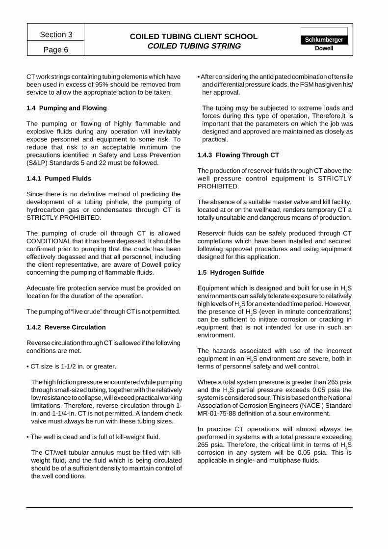
CT work strings containing tubing elements which havebeen used in excess of 95% should be removed fromservice to allow the appropriate action to be taken.
1.4 Pumping and Flowing
The pumping or flowing of highly flammable andexplosive fluids during any operation will inevitablyexpose personnel and equipment to some risk. Toreduce that risk to an acceptable minimum theprecautions identified in Safety and Loss Prevention(S&LP) Standards 5 and 22 must be followed.
1.4.1 Pumped Fluids
Since there is no definitive method of predicting thedevelopment of a tubing pinhole, the pumping ofhydrocarbon gas or condensates through CT isSTRICTLY PROHIBITED.
The pumping of crude oil through CT is allowedCONDITIONAL that it has been degassed. It should beconfirmed prior to pumping that the crude has beeneffectively degassed and that all personnel, includingthe client representative, are aware of Dowell policyconcerning the pumping of flammable fluids.
Adequate fire protection service must be provided onlocation for the duration of the operation.
The pumping of “live crude” through CT is not permitted.
1.4.2 Reverse Circulation
Reverse circulation through CT is allowed if the followingconditions are met.
• CT size is 1-1/2 in. or greater.
The high friction pressure encountered while pumpingthrough small-sized tubing, together with the relativelylow resistance to collapse, will exceed practical workinglimitations. Therefore, reverse circulation through 1-in. and 1-1/4-in. CT is not permitted. A tandem checkvalve must always be run with these tubing sizes.
• The well is dead and is full of kill-weight fluid.
The CT/well tubular annulus must be filled with kill-weight fluid, and the fluid which is being circulatedshould be of a sufficient density to maintain control ofthe well conditions.
• After considering the anticipated combination of tensileand differential pressure loads, the FSM has given his/her approval.
The tubing may be subjected to extreme loads andforces during this type of operation, Therefore,it isimportant that the parameters on which the job wasdesigned and approved are maintained as closely aspractical.
1.4.3 Flowing Through CT
The production of reservoir fluids through CT above thewell pressure control equipment is STRICTLYPROHIBITED.
The absence of a suitable master valve and kill facility,located at or on the wellhead, renders temporary CT atotally unsuitable and dangerous means of production.
Reservoir fluids can be safely produced through CTcompletions which have been installed and securedfollowing approved procedures and using equipmentdesigned for this application.
1.5 Hydrogen Sulfide
Equipment which is designed and built for use in H2S
environments can safely tolerate exposure to relativelyhigh levels of H
2S for an extended time period. However,
the presence of H2S (even in minute concentrations)
can be sufficient to initiate corrosion or cracking inequipment that is not intended for use in such anenvironment.
The hazards associated with use of the incorrectequipment in an H
2S environment are severe, both in
terms of personnel safety and well control.
Where a total system pressure is greater than 265 psiaand the H
2S partial pressure exceeds 0.05 psia the
system is considered sour. This is based on the NationalAssociation of Corrosion Engineers (NACE ) StandardMR-01-75-88 definition of a sour environment.
In practice CT operations will almost always beperformed in systems with a total pressure exceeding265 psia. Therefore, the critical limit in terms of H
2S
corrosion in any system will be 0.05 psia. This isapplicable in single- and multiphase fluids.

COILED TUBING CLIENT SCHOOLCOILED TUBING STRING Page 7
Section 3Schlumberger
Dowell
1.5.1 Determining Sour Status
To simplify the procedure in determining whether a wellis to be considered a “sour well” and initiate thecorresponding requirements of equipment andpersonnel safety, the following recommendations aremade.
It should be noted that these are minimumrecommendations; application of more stringent limitsmay be justified by local requirements or clientpreference.
• Any well on which an acid treatment is to be performed,and which has or has had any history of H
2S, will be
regarded as an H2S well.
• Any well on which the CT will be exposed to a totalsystem pressure less than 5000 psi, and an H
2S level
in excess of 10 ppm, will be regarded as an H2S well.
• Any well on which the CT will be exposed to a totalsystem pressure greater than 5000 psi containing anylevel of H
2S will be regarded as an H
2S well.
• Only equipment that can be positively identified assuitable for use in an H
2S environment (as specified by
NACE Standard MR -01-75-88 and API R49) shouldbe used when working on a well that is known orsuspected to contain H
2S.
2 COILED TUBING FORCES
When CT is run into or pulled out of a vertical well, it isrelatively easy to predict what will be the indicatedweight of the tubing string.The tubing weight per foot, ormeter, is known so the weight of the string will correspondto the length hanging in the well, with some correctionbeing made for the effects of buoyancy. Thus, theweight of the string as shown on the weight indicatordisplay on the surface gives a primary indication of theforces being applied to the CT downhole.
In highly deviated wellbores, the forces required to pushthe CT along the wellbore cannot be accuratelydetermined by the weight indicator display alone. Anumber of forces which act on the CT must be taken intoaccount to predict the loads that the tubing will besubjected to in the wellbore.
The CoilCADE computer program has been developedby Dowell to model the forces acting on the CT undergiven conditions. It is thereby possible to determine theloads on the CT string, enabling efficient job design priorto the operation.
The CoilCADE Tubing Forces Model (TFM) outputs areused to assist in the design of CT operations which aresafe and reliable, and also predict the maximum depthwhich a tool string may be run in horizontal and highlydeviated wellbores. A plot of the anticipated weightindicator load against the measured depth is usedduring the job as a means of checking and interpretingany anomalous conditions.
Most models or calculations used to determine forcesacting on the CT divide the well and tubing string intosections or elements. The resultant load is then calculatedfor each component in each element. In this way it ispossible to examine the effects over the length of thetubing and not only at the top or bottom of the tubingstring.
COILED TUBING CLIENT SCHOOLCOILED TUBING STRING
Section 3
Page 8Schlumberger
Dowell
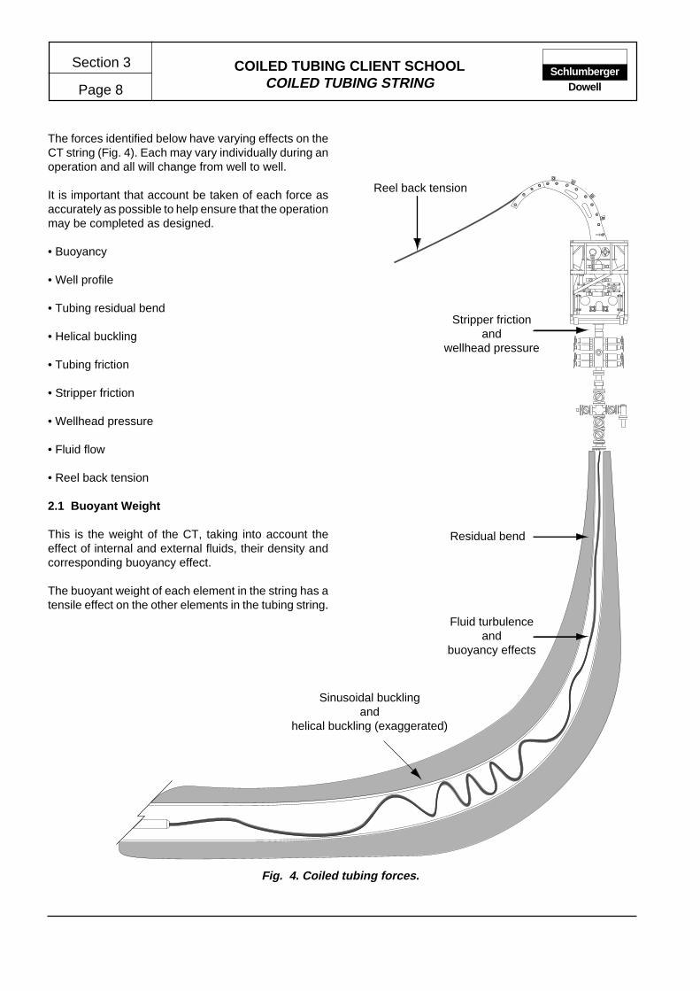
Fig. 4. Coiled tubing forces.
Reel back tension
Stripper frictionand
wellhead pressure
Residual bend
Fluid turbulenceand
buoyancy effects
Sinusoidal bucklingand
helical buckling (exaggerated)
The forces identified below have varying effects on theCT string (Fig. 4). Each may vary individually during anoperation and all will change from well to well.
It is important that account be taken of each force asaccurately as possible to help ensure that the operationmay be completed as designed.
• Buoyancy
• Well profile
• Tubing residual bend
• Helical buckling
• Tubing friction
• Stripper friction
• Wellhead pressure
• Fluid flow
• Reel back tension
2.1 Buoyant Weight
This is the weight of the CT, taking into account theeffect of internal and external fluids, their density andcorresponding buoyancy effect.
The buoyant weight of each element in the string has atensile effect on the other elements in the tubing string.
COILED TUBING CLIENT SCHOOLCOILED TUBING STRING Page 9
Section 3Schlumberger
Dowell
2.2 Well Profile
The profile of a well or completion can affect the load orforce applied to the tubing string in two ways.
• Low Side Drag
The buoyant weight of a tubing string, which is lyingagainst the low side of the well, will vary with thedeviation of the well. As the deviation changes, theamount of friction due to buoyant weight will alsochange.
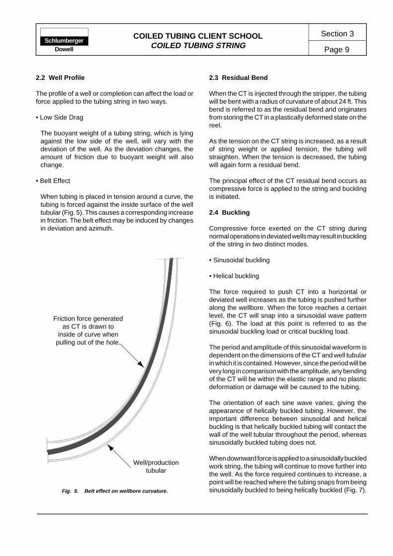
• Belt Effect
When tubing is placed in tension around a curve, thetubing is forced against the inside surface of the welltubular (Fig. 5). This causes a corresponding increasein friction. The belt effect may be induced by changesin deviation and azimuth.
2.3 Residual Bend
When the CT is injected through the stripper, the tubingwill be bent with a radius of curvature of about 24 ft. Thisbend is referred to as the residual bend and originatesfrom storing the CT in a plastically deformed state on thereel.
As the tension on the CT string is increased, as a resultof string weight or applied tension, the tubing willstraighten. When the tension is decreased, the tubingwill again form a residual bend.
The principal effect of the CT residual bend occurs ascompressive force is applied to the string and bucklingis initiated.
2.4 Buckling
Compressive force exerted on the CT string duringnormal operations in deviated wells may result in bucklingof the string in two distinct modes.
• Sinusoidal buckling
• Helical buckling
The force required to push CT into a horizontal ordeviated well increases as the tubing is pushed furtheralong the wellbore. When the force reaches a certainlevel, the CT will snap into a sinusoidal wave pattern(Fig. 6). The load at this point is referred to as thesinusoidal buckling load or critical buckling load.
The period and amplitude of this sinusoidal waveform isdependent on the dimensions of the CT and well tubularin which it is contained. However, since the period will bevery long in comparison with the amplitude, any bendingof the CT will be within the elastic range and no plasticdeformation or damage will be caused to the tubing.
The orientation of each sine wave varies, giving theappearance of helically buckled tubing. However, theimportant difference between sinusoidal and helicalbuckling is that helically buckled tubing will contact thewall of the well tubular throughout the period, whereassinusoidally buckled tubing does not.
When downward force is applied to a sinusoidally buckledwork string, the tubing will continue to move further intothe well. As the force required continues to increase, apoint will be reached where the tubing snaps from beingsinusoidally buckled to being helically buckled (Fig. 7).
Friction force generatedas CT is drawn to
inside of curve whenpulling out of the hole.
Well/productiontubular
Fig. 5. Belt effect on wellbore curvature.

COILED TUBING CLIENT SCHOOLCOILED TUBING STRING
Section 3
Page 10Schlumberger
Dowell
Fig. 6. Sinusoidal buckling.
Period (wavelength)
Amplitude
Fig. 7. Helical buckling.
Shorteningperiod
As with sinusoidal buckling, the wave pattern isdependent on the CT and well tubular dimensions andis within the elastic range of the CT. The direction of thehelix will change over the length of the buckled sectionof tubing, thus the number of rotations and inducedtorque over the total length of the buckled sectionremains zero.
When the tubing is helically buckled, the resulting helixapplies force against the side of the well tubular. However,the tubing can still be moved further into the wellbore.The increased friction caused by forcing the tubingfurther into the wellbore causes the period of helix toshorten, which in turn further increases the friction. At acertain point, the friction forces become greater than theforce pushing the tubing. When this point is reached, itis impossible to push the tubing further into the wellbore.This condition is referred to as helical lockup.
Following helical lockup, it will still be possible to injecttubing into the well; however, this will only result inincreasing the amount of buckled tubing in the well. TheBHA cannot be pushed further into the well followinghelical lockup. Determining the point at which lockupoccurs is a major element of CT job design work inhorizontal and deviated well applications.
Where the wellbore contains a curvature, either as aresult of deviation or azimuth change, the sinusoidal
and helical buckling loads will be increased. This is dueto the increased support the well tubulars afford to theCT. Increasing the compressive force tends to stabilizethe CT by forcing it into the trough of the curve. A largerforce is required to move the CT out of the trough into asine or helical waveform.
2.5 Fluid Turbulence
When fluid is flowing at high rates through the CT orthrough the surrounding annulus, the CT will tend tovibrate. This vibration will effectively decrease the frictionbetween the CT and the well tubular in which it iscontained.
2.6 Stripper Friction
The seal provided by the stripper to secure well pressurecauses a friction force to be applied to the tubing. Whenthe stripper operating pressure or wellhead pressure isincreased, the friction caused by the stripper seal areawill also increase.
When operating at high wellhead pressures, this frictionbecomes a significant factor. In extreme cases thefriction imposed by the stripper seal area may make itdifficult to inject the CT through the stripper assembly.
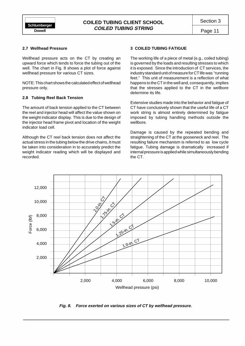
COILED TUBING CLIENT SCHOOLCOILED TUBING STRING Page 11
Section 3Schlumberger
Dowell
2.7 Wellhead Pressure
Wellhead pressure acts on the CT by creating anupward force which tends to force the tubing out of thewell. The chart in Fig. 8 shows a plot of force againstwellhead pressure for various CT sizes.
NOTE: This chart shows the calculated effect of wellheadpressure only.
2.8 Tubing Reel Back Tension
The amount of back tension applied to the CT betweenthe reel and injector head will affect the value shown onthe weight indicator display. This is due to the design ofthe injector head frame pivot and location of the weightindicator load cell.
Although the CT reel back tension does not affect theactual stress in the tubing below the drive chains, it mustbe taken into consideration in to accurately predict theweight indicator reading which will be displayed andrecorded.
3 COILED TUBING FATIGUE
The working life of a piece of metal (e.g., coiled tubing)is governed by the loads and resulting stresses to whichit is exposed. Since the introduction of CT services, theindustry standard unit of measure for CT life was “runningfeet.” This unit of measurement is a reflection of whathappens to the CT in the well and, consequently, impliesthat the stresses applied to the CT in the wellboredetermine its life.
Extensive studies made into the behavior and fatigue ofCT have conclusively shown that the useful life of a CTwork string is almost entirely determined by fatigueimposed by tubing handling methods outside thewellbore.
Damage is caused by the repeated bending andstraightening of the CT at the gooseneck and reel. Theresulting failure mechanism is referred to as low cyclefatigue. Tubing damage is dramatically increased ifinternal pressure is applied while simultaneously bendingthe CT.
Fig. 8. Force exerted on various sizes of CT by wellhead pressure.
For
ce (
lbf)
Wellhead pressure (psi)
2,000 4,000 6,000 8,000 10,000
2,000
4,000
6,000
8,000
10,000
12,000
1.0-in. CT1.25-in. C
T1.5-in. C
T1.75
-in. C
T
2.0-
in. C
T

COILED TUBING CLIENT SCHOOLCOILED TUBING STRING
Section 3
Page 12Schlumberger
Dowell
As a result of the research and development efforts, aCoilCADE CT fatigue tracking system has beenimplemented. This system takes account of the factorsthat are now known to have a major influence over theuseful life of a CT string.
The physical and metallurgical properties of CT havesignificantly improved in recent years. This combinedwith improved manufacturing techniques and qualitycontrol procedures has resulted in the production of aconsistent product with a predictable performance.
Early manufacturing processes required that the CTstring be assembled using butt welds to join severalshort lengths of tubing. This introduced a relativeweakness into the CT material adjacent to the weld site(Fig. 9). Tubing failures in this type of work string almostalways occur within this heat-affected zone (HAZ).
Most CT strings are now being formed from a continuouslength of strip material. The short lengths of flat stripmaterial, which are used to assemble the final stringlength, are welded and heat treated in a closely controlledprocess which effectively removes any HAZ from thestrip material.
3.1 Stress and Strain
A stress is the internal reaction of a body to an externalforce. It is generally described as the internal forceacting across a unit area in a solid material in resistingthe separation, compacting or sliding that tends to beinduced by external forces. Stress analysis is thedetermination of the stresses produced in a solid bodywhen subjected to various external forces.Since stress is a function of the area of an element,stress values are expressed in force/area (e.g., psi).
Whenever a stress is applied to an element, the elementreacts by changing its dimensions, i.e., it is deformed.Strain is a measure of this deformation and is defined asthe change in the dimension of the element divided byits original dimension.
The units of strain are consequently expressed as in./in., mm/mm, etc.... or sometimes as a percentage.
Any stress applied to an element will always have anassociated strain; a bending stress causes a bendingstrain.
In any operation CT is exposed to several stresses,some of which apply at specific points while others applythroughout the entire system. The primary stresses thatare applied to a CT string are shown in Fig. 10.
The types of stress identified in Fig. 11 have been foundto be the principal stresses that affect a CT work string.
• Hoop stress (circumferential)
Internal pressure applied to a CT string produces ahoop stress which is applied to the full length of thestring.
• Bending stress
A bending stress is produced when the CT is beingbent over the gooseneck or onto the reel.
• Radial stress
The radial stress and associated radial strain onlybecome a significant factor when the wall thickness ofthe CT is reduced as a result of the combined effectsof the hoop strain and bending strain.
Heat-affected zones
CT butt weld
Fig. 9. Heat-affected zones adjacent to a CT butt weld.

COILED TUBING CLIENT SCHOOLCOILED TUBING STRING Page 13
Section 3Schlumberger
Dowell
Pressure andbending
Pressure andtension
Pressure andbending
Pressure andcompression
Pressure andtension
Possibletorque
Fig.11. Principal CT stresses.
The plastic and elastic regions shown in Fig. 13 identifyimportant differences in material behavior.
If the applied stress is kept within the range OA, e.g.,point Y, and then released, the strain will also return tozero. The material is said to behave elastically in thisinterval and is the reason for referring to Point A as theelastic limit.
Elastic deformation represents an actual change in thedistance between atoms of a material when a load isapplied. When the load is released, the atomic structurereturns to its original position.
A stress/strain plot of the release will follow the sameline OY. There is no permanent damage or deformationto the material when the stresses are in this range.
If the applied stress is in the range AB, e.g., Point X, andis then released, a stress/strain plot of the release willnot follow a line XO.Although the stress returns to zero, a strain (Z) willremain, i.e., there is some permanent change to thematerial.
The line XZ, which is parallel to line OA, shows how thestress will be removed.
This is called plastic deformation and is the reason whythe interval AB is referred to as the plastic region. Aplastic deformation represents a permanent change inthe atomic structure of a material when the stress isremoved.
Radial stress
Bendingstress
Hoop stress
The tension applied to the CT downhole is the result oftensile stresses which terminate at the injector-headchains. The tension to which the CT is subjected atsurface is negligible under normal operating conditions.
3.2 Stress-Strain Theory
For most metals, there is a well-established relationshipbetween the stresses applied to an element and theresulting strains. This general relationship is graphicallyshown in Fig 12.
There are two distinct parts to the relationship as shownby the lines OA and AB . In the line OA, the strain isdirectly proportional to the applied stress, i.e., if a smallamount of pull is applied,the material stretches a little. Iftwice as much pull is applied, it stretches twice as much(however, the material will always return to its originaldimension). This applies up to a limit corresponding toPoint A, which is known as the yield point .The stress (C) applied at Point A is known as the yieldstrength.
Beyond Point A, the behavior of the material changes.A small change in stress will result in a large strain. If itis pulled beyond its yield point, the material stretchessignificantly until it breaks. The breaking pointcorresponds to Point B.
The applied stress (D) at Point B is known as theultimate strength of the material. The strain (E) at PointB is known as the ultimate strain.
Fig. 10. Primary Stress effecting the CT string.

COILED TUBING CLIENT SCHOOLCOILED TUBING STRING
Section 3
Page 14Schlumberger
Dowell
The new elastic limit for the material is now somewherebetween points F and X, but its exact position dependson the type of material and the stresses involved. Thenext time a stress is applied, it will go up the line ZX andnot OA.
It is important to understand that every time a materialis stressed beyond the yield point, some permanentdamage occurs.
3.3 Stress/Strain Theory Applied to Coiled Tubing
The plot and chart in Fig. 14 identify some of thespecifications generally used by manufacturers todescribe the CT.
By quoting minimum values, the manufacturer isguaranteeing that this is the worst case. In fact, mostbatches of 70,000-psi CT material have actual yieldstrengths of about 75,000 psi and ultimate strengths ofaround 80,000 psi.
These values are a function of the alloy only, and are notrelated to the pipe size or wall thickness.
All manufacturers provide data similar to those shown inFig. 2 (Coiled Tubing Data). The yield and ultimatevalues of load capacity are obtained by multiplying therelevant material properties of the alloy (i.e., 70,000 psiand 75,000 psi) by the wall cross-sectional area to givethe load capacity (lb).
Two important points should be noted when consideringstresses applied to the CT:
• The stress/strain theory applies to each of the differentstresses applied to the CT, e.g., bending stress, hoopstress, radial stress or the tensile stress acting on theCT while in the well.
• The stresses can be simplified into two groups– thoseacting on the CT when it is in the well and those actingon the CT at the surface.
3.3.1 Stress Applied in the Well
The CT is straightened by the injector-head chains, andthe string weight is then held by the chains. Below thechains the CT is usually hanging freely in the well(except in deviated/horizontal holes). The CT stressesare always within the elastic region except in veryextreme cases.
Although other stresses are present, the primary stressacting on the CT in the well is tension.
Factors that can affect CT tension are buoyancy, wellgeometry (frictional drag), obstructions and stuck pipe.If the tubing becomes stuck in the hole and the operatorcontinues to pull on the CT, the tension in the tubingwould increase until the yield stress is reached and theCT would then begin to plastically deform.Once the ultimate stress of the material is reached, afailure will occur. Normally, the CT would break justbelow the injector head if this were allowed to happen.Consider an example of the tension in a CT string in awell (Fig. 15).
Assume the minimum yield strength of the CT is 70,000psi. The area of 1-1/4-in. OD x 0.087-in. wall thickness
Fig. 12. General stress/strain plot.
D
C
O
B
E
Plastic region
Elastic region
D
C
O
B
E
Plastic region
A F
XA
Y
Elastic region
STRAIN (∑)
ST
RE
SS
(∂)
STRAIN (∑)
ST
RE
SS
(∂)
Fig. 13. Plastic deformation plot.

COILED TUBING CLIENT SCHOOLCOILED TUBING STRING Page 15
Section 3Schlumberger
Dowell
Fig. 15. An example of CT tension in the well.
CT is 0.318 in.2 The minimum yield load capacity of 1-1/4-in. OD x 0.087-in. CT is 22,260 lb. The minimumultimate load capacity is 25,440 lb, and the weight is1.081 lb/ft.
If the CT is run to a depth of 15,000 ft, the string weightwill be 16,215 lb (without any buoyancy effect or supportfrom a deviated wellbore). This load is well within theelastic region.
Torque can be applied to the tubing in several ways.The tubing will follow a helical path down the wellboreand effectively produce a minimal torque stress value.However, the most severe case of torque stress ariseswhen downhole motors are run on the CT. A typicaldownhole motor for use on 1-1/4-in. CT can generateabout 100 ft/lb of torque which is well below the torqueyield limit (504 ft/lb for 0.087-in. wall thickness) of theCT. However, as larger and more efficient motors aredeveloped, consideration should be given to this factor.
3.3.2 Stress Applied at the Surface
A characteristic of bending strain is that the bottomportion of the tubing decreases in length, resulting in anegative bending stress and strain (compression). Thetop portion increases in length, resulting in a positivebending stress and strain (tension).
The hoop strain which is considered relevant may besimply stated as the diametral growth of the CT due tohigh internal pressure.
The radial strain becomes a significant factor once thewall thickness is reduced, because of the combinationof the hoop and bending strains.
One strain acting independently will cause less severeresults than a combination of strains simultaneouslyproduced. In fact, the CT is subjected to a combinationof strains a majority of the time. As a result a multiaxialstress/strain analysis is required to determine thecombined stress to which the CT is being subjected.Multiaxial forces act in the directions of the three
Plastic region
LOA
D C
AP
AC
ITY
(lb
w)
STRAIN (∑)
Elastic region
22,260 lb
24,440 lb
Yieldpoint
Yield strength
Ultimate strength
Elastic region
STRAIN (∑)
ST
RE
SS
(∂)
Property Value
Minimum yield strength 70,000 psi
Minimum tensile strength 75,000 psi
Minimum elongation 30%(ultimate strain)
Fig. 14. General stress/strain plot.

COILED TUBING CLIENT SCHOOLCOILED TUBING STRING
Section 3
Page 16Schlumberger
Dowell
coordinate axes (x,y and z) and produce stresses notequivalent to zero. There are many mathematicalmodels which predict the life of a given alloy undercertain test conditions. However, an exact cumulativestress/strain diagram for CT does not yet exist, althoughit is believed that the curve resembles that shown in Fig.16 for the “top” portion of a piece of CT.
This graph depicts the combined effect of the threeprimary strains due to continuous reciprocation of theCT at the surface.
Point 0 on the graph represents the tubing after beingstress relieved at the factory but before it has beenspooled onto a reel for the first time (it has never beenbent).
Tubing which has never been bent behaves elastically.As CT is spooled onto a reel, the material is subjectedto combined postyield strains equivalent to Point 1.
Once it is spooled, it is then called CT and practically theentire cross section is plastically deformed. This can beobserved by cutting a section of tubing from the reel andlaying it on the ground. The CT is no longer straight butis curved due to the residual stress in the CT which isinduced by plastic deformation.
However, tubing that has been plastically deformed willstill behave elastically, e.g., if a 3-ft length of 1-1/4-in.CT is bent 2 in. and the force is then removed, the CTwill return to its original shape.
Point 2 of the plot corresponds to residual strains whichremain after the tubing has been rolled off of the reel andstraightened as it approaches the gooseneck.
As the tubing is again bent over the gooseneck, combinedstrains increase to those at Point 3. Restraightening thetubing within the injector head creates a strain reversalto Point 4. A subsurface tensile load lower than the yieldpoint of the CT material is represented at Point 5.
On pulling out of the hole, the pipe returns through thechains and travels over the gooseneck (point 6).
As the cycles accumulate, the combined strain increasesuntil the ultimate strain is exceeded and the pipe fails(fatigue). At the point of failure, the final stress will havebeen produced, which has in turn caused the tubing toreach its ultimate strain.
Fig. 16. Stress/strain diagram for CT during spooling and operation.
5
4, 6
3, 7
1, 9
2, 8
Elastic region
STRAIN (∑)
CO
MB
INE
D S
TR
ES
S (
∂)
Plastic region
Plastic region
Elastic region
Rupture
Yieldstress
1 3 6
0
2 4
The numbers on the illustrationabove correspond to the numberedpoints on the stress strain diagram.
COILED TUBING CLIENT SCHOOLCOILED TUBING STRING Page 17
Section 3Schlumberger
Dowell
3.4 Fatigue Testing
The first documented Dowell CT fatigue tests wereperformed in Holland in 1988. At that time a piece of CTwas positioned over the gooseneck with a 7500-kgweight added to the tubing below the injector-headchains and a 50-kg weight positioned on the oppositeend to ensure the CT remained wrapped around thegooseneck. The reel was not used.
The injector head was elevated, and the tests wereconducted using a cycling stroke of approximately 26 ft(8 m) and an internal pressure of 5000 psi. With the testparameters fixed, the number of “cycles,” the OD of theCT and the skate pressures were recorded.
These tests were not truly representative of an actualjob as all of the strain reversals associated with the CTcoming on and off the reel were not simulated. However,they were the first documented tests which gave aqualitative idea of the factors that are important to thefatigue life, and therefore safe working life of the tubing.
An important factor identified during the tests is thatvarying skate pressures affect the life of the CT. Theless the skate pressure applied, the longer the tubinglife.
Full-scale fatigue tests conducted by the Dowell CoiledTubing R&E Group (TCT) began in 1989. Various CTgeometries and internal working pressures have beentested to destruction, and testing continues as new CTproducts are commercialized by manufacturers.
The above tests fully reproduced actual job conditionsand, by using the T.I.M. and strain gages, produced datanot obtained in previous testing.
The eventual failure of CT due to fatigue was confirmedto be a result of cumulative deformation occurring everytime the pipe is bent. To determine the evolution of thedamage, cumulative strains were monitored. The straindata were then input to several local strain-based fatiguelife prediction theories.
3.4.1 Fatigue Test Results
The tests revealed two physical, easily measurablephenomena which can be exploited in the field. Fieldsystems track the condition of the pipe with respect tothese phenomena and correlate them to the fatigue lifeof a CT work string.
• Bending Under Pressure
There is a distinct relationship between the number oftrips to failure and the simultaneous internal pressure.The higher the internal pressure, the less the numberof trips to failure (e.g., 199 trips at 300 psi versus 41trips at 5000 psi). If there is a butt weld within thesection, the number of trips to failure will be dramaticallyreduced due to the changed metallic structure in theHAZ.
• Diametric Growth
The CT grows in diameter as trips are made with aninternal pressure applied. This growth is significantand in some cases is severe, e.g., during one of thetests at 5000 psi with 1-1/4-in. CT, the pipe balloonedfrom its original 1.25 in. out to 1.47 in.
Under static conditions, the levels of pressure that aretypically applied will not result in any permanentdeformation, because the associated stresses are wellwithin the elastic limit. However, when the tubing isbeing bent sufficiently to make the bending stressplastic, any other stress that is applied at the same timewill also have plastic strains associated with it. Thisapplies even if these additional stresses appliedindividually would be elastic. Therefore, bending the CTwith a high internal pressure, i.e.,greater than 3000 psi,will cause some diametric growth.
If the CT is bent with no internal pressure, there will beno significant growth in diameter.
Approximately 60% of the CT jobs performed worldwidehave an applied internal pressure greater than 3000 psi.Therefore, the majority of CT workstrings will be subjectto ballooning in the sections that have been cycled at ahigher pressure.
From the results of these fatigue tests, field qualitysystems have been developed:
• A fatigue tracking system comprising on-site dataacquisition supplying data for the CoilCADE reeldatabase. The CoilLIFE computer model can then beused to predict the remaining life of the CT work string.
• A T.I.M. real-time inspection system will accuratelymeasure the diameter of the CT to alert operatingpersonnel if the predefined dimensional limits of theCT are exceeded.

COILED TUBING CLIENT SCHOOLCOILED TUBING STRING
Section 3
Page 18Schlumberger
Dowell
Other significant findings from the test results are listedbelow:
• The CT always failed at the portion that had madecomplete trips (from the reel through the injector-headchains and back onto the reel).
• The CT fails at the maximum diameter of the balloonedportion and generally on the underside. In the vastmajority of the tests, this occurred while passing overthe gooseneck coming out of the hole.
• At the beginning of the tests, the CT assumes anelliptical shape such as that shown in Fig. 17. At higherpressures, the minor axis grows to become the majoraxis and is also dependent on the number of tripsperformed.
• The top portion of the CT often conforms to the shapeof a wave just before failure as shown in Fig. 18. Thewave shape is more pronounced at higher internalpressures and barely visible at lower internal pressures.
• The initial cracking (which initiates failure) begins onthe inside suface of the tubing.
• The sequence of pressure and bending cycles must beconsidered to determine CT life.
• The CT behaves elastically when subjected to aninternal pressure alone. However, when the CT isbent at the same time, the CT then behaves plastically.
• Bending strains remain essentially constant to failure
at all pressure levels; however, hoop strains increasewith increasing internal pressure.
• Test measurements showed that CT will either notlengthen or only lengthen slightly with an appliedinternal pressure, and that most of the damage iscaused by diametric growth (ballooning).
• The longitudinal weld does not seem to have an effecton the longevity of the CT.
• Thicker walled pipe gives a longer cycle life.
• The smaller the OD of the CT, the more cycles that canbe made before failure.
• The less skate tension, the longer the tubing life.
• The tests with the butt weld revealed the regions oflocalized plastic deformation were located approxi-mately 0.2 in. on either side of the weld, in the HAZ.
• Reversing the direction of curvature also reduces thelife of the CT. Reversal of the CT is commonly causedby positioning the levelwind too low. Theoretical pre-dictions suggest that as much as a 25% reduction inthe life of the CT may result if a reversal is present onevery trip throughout the life of the CT.
• Although a section of CT fails, the remainder of thestring is not affected in the same manner as the failedsection unless subjected to exactly the same conditions.Therefore, the entire string should be evaluated todetermine whether it should be repaired or discarded.
Prior to the conclusion of the tests outlined above, there
XX
Y
Y
Ideal geometry
Typicalnew CT
geometry
Geometry after repeatedpasses over the
gooseneck at highpressure
Geometry just prior totubing failure at high
pressure
Tubing shows grosseccentricity due to
swelling with internalpressure and
deformation by thegripper blocks.
Tubing showseccentricity due to
flattening as it passesover the gooseneck and
reel drum.
Tubing circular, tubingslightly under size.
Fig. 17. Ovality changes in CT.
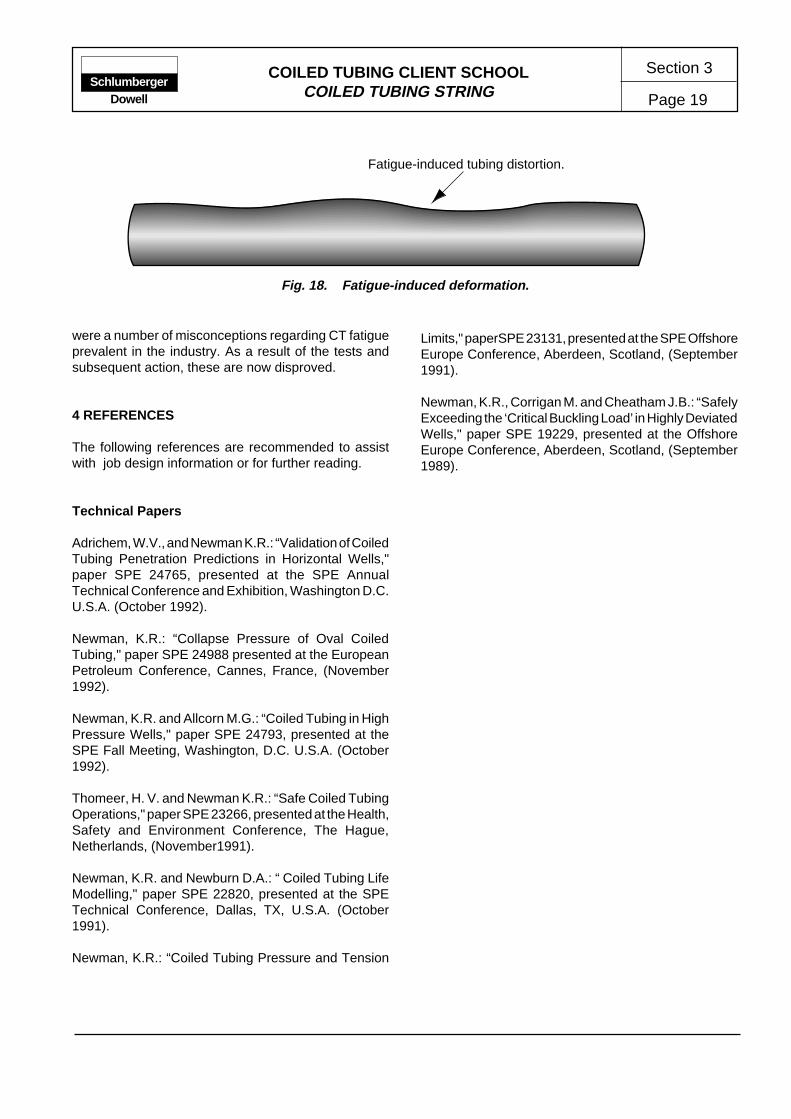
COILED TUBING CLIENT SCHOOLCOILED TUBING STRING Page 19
Section 3Schlumberger
Dowell
Fatigue-induced tubing distortion.
Fig. 18. Fatigue-induced deformation.
were a number of misconceptions regarding CT fatigueprevalent in the industry. As a result of the tests andsubsequent action, these are now disproved.
4 REFERENCES
The following references are recommended to assistwith job design information or for further reading.
Technical Papers
Adrichem, W.V., and Newman K.R.: “Validation of CoiledTubing Penetration Predictions in Horizontal Wells,"paper SPE 24765, presented at the SPE AnnualTechnical Conference and Exhibition, Washington D.C.U.S.A. (October 1992).
Newman, K.R.: “Collapse Pressure of Oval CoiledTubing," paper SPE 24988 presented at the EuropeanPetroleum Conference, Cannes, France, (November1992).
Newman, K.R. and Allcorn M.G.: “Coiled Tubing in HighPressure Wells," paper SPE 24793, presented at theSPE Fall Meeting, Washington, D.C. U.S.A. (October1992).
Thomeer, H. V. and Newman K.R.: “Safe Coiled TubingOperations," paper SPE 23266, presented at the Health,Safety and Environment Conference, The Hague,Netherlands, (November1991).
Newman, K.R. and Newburn D.A.: “ Coiled Tubing LifeModelling," paper SPE 22820, presented at the SPETechnical Conference, Dallas, TX, U.S.A. (October1991).
Newman, K.R.: “Coiled Tubing Pressure and Tension
Limits," paperSPE 23131, presented at the SPE OffshoreEurope Conference, Aberdeen, Scotland, (September1991).
Newman, K.R., Corrigan M. and Cheatham J.B.: “SafelyExceeding the ‘Critical Buckling Load’ in Highly DeviatedWells," paper SPE 19229, presented at the OffshoreEurope Conference, Aberdeen, Scotland, (September1989).

Section 4
Page 1COILED TUBING CLIENT SCHOOL MANUAL
COILED TUBING JOB DESIGN
ContentsPageContents Page
SchlumbergerDowell
service is required (e.g., matrix stimulation or squeezecementing). In many cases a number of alternativetreatments, or means of application may be identified.While some may be quickly dismissed due to economicor availability reasons, it is prudent to assess all optionsto ensure that the selected treatment is optimal in termsof efficiency and economics.
A major component in the design of Dowell CT operationsis the use of CoilCADE* software. CoilCADE softwareprovides design support for a wide range of CTapplications through validated models which are used tosimulate conditions anticipated during the operation.The resulting outputs are used to confirm the operationcan be safely completed under the given conditions.
Databases within CoilCADE are used to track the history,and more importantly the fatigue to which CT workstringsmay be subjected.
The illustration in Fig. 1 shows a generalized CT jobdesign sequence. In complex or sensitive applications,several iterations of each stage may be required toensure the desired results. Conversely, the design ofroutine treatments is often driven and tuned byexperience.
The evaluation phase is a necessary, though oftenoverlooked requirement to complete the CT operationand assess the design efficiency.
* Mark of Schlumberger
1 INTRODUCTION ......................................... 12 JOB DESIGN DATA..................................... 3
2.1 Associated Services .......................... 33 CoilCADE SOFTWARE ............................... 3
3.1 Tubing Forces Module ....................... 43.2 CoilLIFE ............................................. 4
3.3 CoilLIMIT ........................................... 53.4 Wellbore Simulator ............................ 53.5 Friction Pressure ............................... 63.6 Foam Cleanout .................................. 6
4 OPERATING LIMITS AND PROCEDURES 65 REFERENCES ............................................ 7
1 INTRODUCTION
As the features and benefits of modern coiled tubingoperations, equipment and downhole tools becomemore complex, the initiation of a thorough and methodicaljob design process becomes essential. Although themajority of the job design process is performed awayfrom the wellsite, many potential execution problems orhazards can be identified. With timely identification,operational problems or hazards may be resolvedwithout jeopardizing the safety of personnel or wellsecurity. Therefore, the job design process must beregarded as an investigation and preparation procedurefor all aspects of the intended operation – not simply theselection of an appropriate treatment, toolstring orequipment configuration.
Fundamental to any job design process is a fullunderstanding of the overall objectives. The ultimatesuccess of the operation will be gauged against theseobjectives, therefore, a clear understanding is essential.In some instances, the objectives may be economicallyor operationally misguided. A joint review of influencingfactors, conducted by operator and contractor personnel,can allow such conditions to be identified. As aconsequence, alternatives can be investigated andselected to provide improved return on investment orgreater operational success.
In almost all CT applications, the workstring functionsas a conveyance method for treatment fluids ortoolstrings. Therefore, to complete a treatment designsome knowledge and understanding of the associated
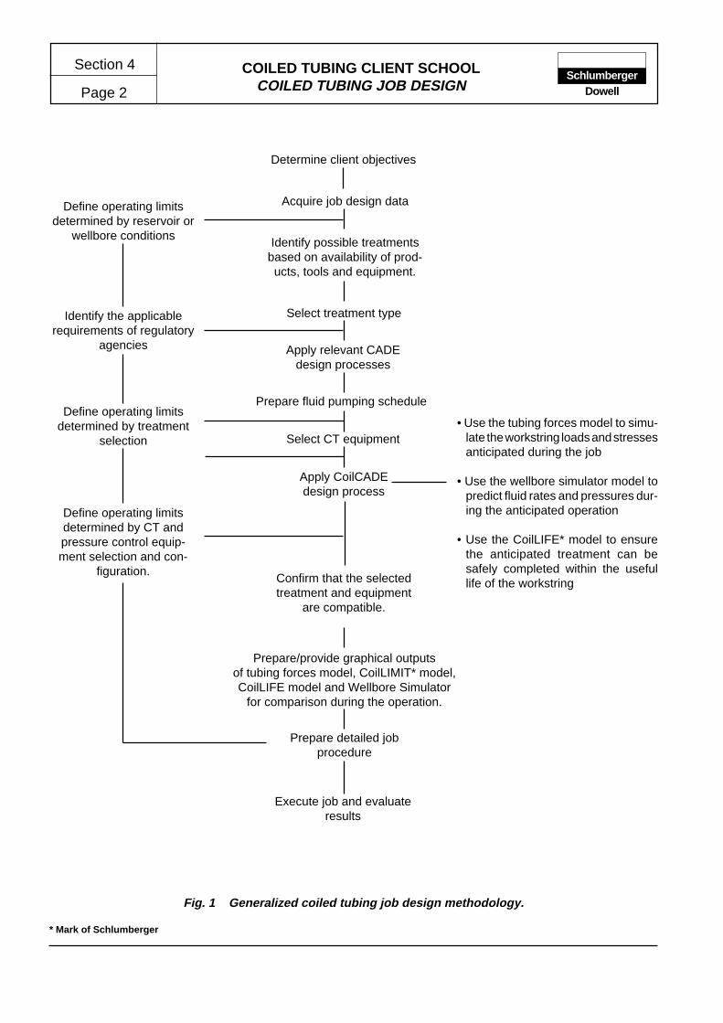
COILED TUBING CLIENT SCHOOLCOILED TUBING JOB DESIGN
Section 4
Page 2Schlumberger
Dowell
Acquire job design data
Determine client objectives
Select CT equipment
Define operating limitsdetermined by reservoir or
wellbore conditions
Identify the applicablerequirements of regulatory
agencies
Define operating limitsdetermined by treatment
selection
Prepare/provide graphical outputsof tubing forces model, CoilLIMIT* model,CoilLIFE model and Wellbore Simulator
for comparison during the operation.
Prepare detailed jobprocedure
Execute job and evaluateresults
Identify possible treatmentsbased on availability of prod-ucts, tools and equipment.
Select treatment type
Apply relevant CADEdesign processes
Apply CoilCADEdesign process
Define operating limitsdetermined by CT andpressure control equip-ment selection and con-
figuration.
Fig. 1 Generalized coiled tubing job design methodology.
• Use the tubing forces model to simu-late the workstring loads and stressesanticipated during the job
• Use the wellbore simulator model topredict fluid rates and pressures dur-ing the anticipated operation
• Use the CoilLIFE* model to ensurethe anticipated treatment can besafely completed within the usefullife of the workstring
* Mark of Schlumberger
Confirm that the selectedtreatment and equipment
are compatible.
Prepare fluid pumping schedule

COILED TUBING CLIENT SCHOOLCOILED TUBING JOB DESIGN Page 3
Section 4Schlumberger
Dowell
2 JOB DESIGN DATA
The data required to enable the job design process to becompleted varies with the type of application and itscomplexity. The principal areas of investigation areshown below and are grouped in three categories: dataobtained from well records, information relating toproduct and service availability, and the requirements ofregulatory agencies.
Well file sourced
• Reservoir parameters
• Wellbore conditions
• Surface or location limitations
Dowell sourced
• Product availability/compatibility
• Equipment and tool availability
Regulatory requirements
• Operational requirements or limitations
The output of representative plots and values fromcomputer models is greatly dependent on the input ofaccurate data. Consequently, some effort should bemade to ensure the accuracy of job design data. Whileacquiring this data, the overall objectives should beconfirmed by investigating the desired changes inwellbore or reservoir conditions.
The design methodology adopted for each job isdependent on the application or operation to becompleted, and in many cases prior experience is thebest guide. However, there are several factors whichapply to all Dowell CT operations and consequentlymust be considered during all phases of the job designand execution.
• Well security - it is essential that adequate well securityis maintained to guard against the exposure of person-nel, equipment and the environment to wellbore pres-sure and fluids.
• Personnel safety - performing the necessary tasksusing the required safety equipment, or with equipmenton standby for immediate use as required.
• Operating limits - the operating and safety limits of allequipment and tools must be known by relevant op-erators. The operation must be designed and executedwithin stated or calculated limits.
• Operating standards - the operation must be executed,as designed, by trained and competent personnel inaccordance with applicable operating practices, regu-lations and safety standards.
2.1 Associated Services
The factors and constraints associated with the designand selection of associated services are contained inthe relevant service line manuals. In this manual,summaries or guidelines are occasionally given forassociated services conveyed by CT. However, in allcases it is recommended that the local Dowell CTrepresentative is consulted during the job design process.
Published articles and technical papers are often usefulreference sources for many aspects of CT and associatedoperations.
3 CoilCADE SOFTWARE
CoilCADE software is an assembled package of modulardesign which allows modifications and additions to beeasily made. The package includes calculation and database modules as well as the capability of severalgraphic and report format outputs. Being modular alsoallows selective, or reiterative use of models during thejob design process.
The CoilCADE software comprises the following principaljob design modules.
• Tubing forces
• CoilLIFE
• CoilLIMIT
• Wellbore simulator
• Friction pressure
• Foam cleanout
The following brief descriptions of CoilCADE modulesand their functionality is provided for general informationpurposes only.
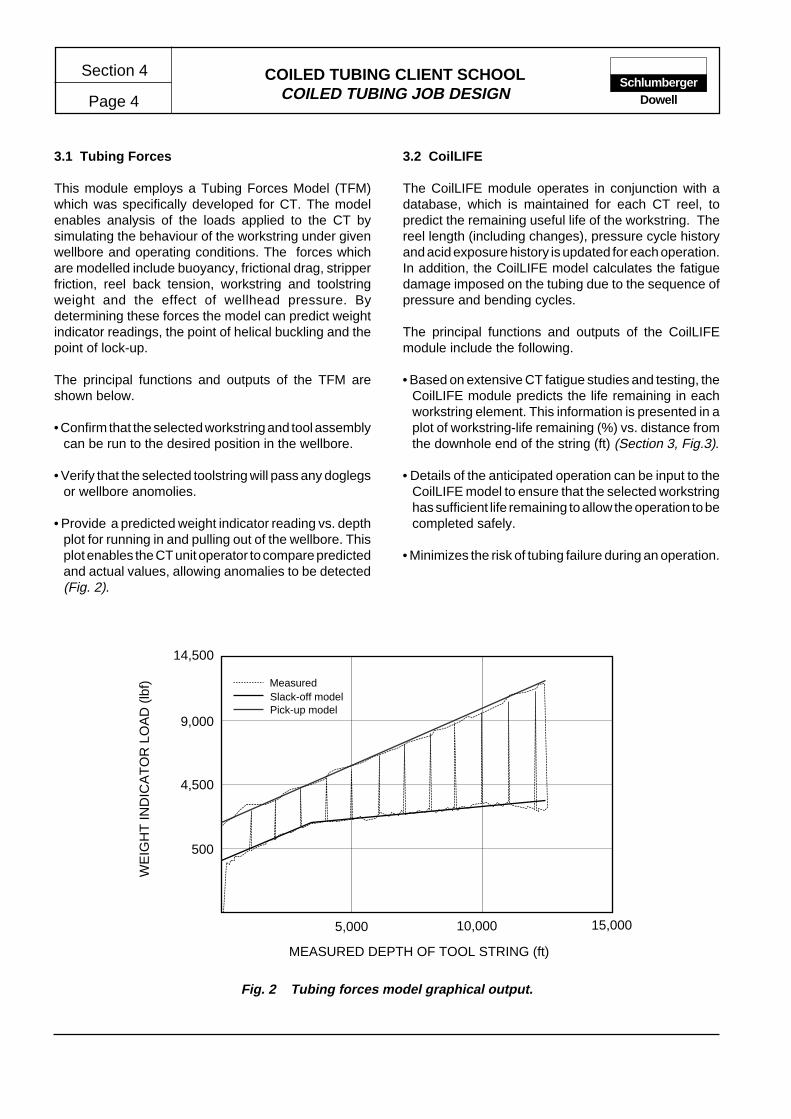
COILED TUBING CLIENT SCHOOLCOILED TUBING JOB DESIGN
Section 4
Page 4Schlumberger
Dowell
3.1 Tubing Forces
This module employs a Tubing Forces Model (TFM)which was specifically developed for CT. The modelenables analysis of the loads applied to the CT bysimulating the behaviour of the workstring under givenwellbore and operating conditions. The forces whichare modelled include buoyancy, frictional drag, stripperfriction, reel back tension, workstring and toolstringweight and the effect of wellhead pressure. Bydetermining these forces the model can predict weightindicator readings, the point of helical buckling and thepoint of lock-up.
The principal functions and outputs of the TFM areshown below.
• Confirm that the selected workstring and tool assemblycan be run to the desired position in the wellbore.
• Verify that the selected toolstring will pass any doglegsor wellbore anomolies.
• Provide a predicted weight indicator reading vs. depthplot for running in and pulling out of the wellbore. Thisplot enables the CT unit operator to compare predictedand actual values, allowing anomalies to be detected(Fig. 2).
3.2 CoilLIFE
The CoilLIFE module operates in conjunction with adatabase, which is maintained for each CT reel, topredict the remaining useful life of the workstring. Thereel length (including changes), pressure cycle historyand acid exposure history is updated for each operation.In addition, the CoilLIFE model calculates the fatiguedamage imposed on the tubing due to the sequence ofpressure and bending cycles.
The principal functions and outputs of the CoilLIFEmodule include the following.
• Based on extensive CT fatigue studies and testing, theCoilLIFE module predicts the life remaining in eachworkstring element. This information is presented in aplot of workstring-life remaining (%) vs. distance fromthe downhole end of the string (ft) (Section 3, Fig.3).
• Details of the anticipated operation can be input to theCoilLIFE model to ensure that the selected workstringhas sufficient life remaining to allow the operation to becompleted safely.
• Minimizes the risk of tubing failure during an operation.
Fig. 2 Tubing forces model graphical output.
500
4,500
9,000
14,500
WE
IGH
T IN
DIC
AT
OR
LO
AD
(lb
f)
MEASURED DEPTH OF TOOL STRING (ft)
5,000 10,000 15,000
MeasuredSlack-off modelPick-up model

COILED TUBING CLIENT SCHOOLCOILED TUBING JOB DESIGN Page 5
Section 4Schlumberger
Dowell
3.3 CoilLIMIT
The CoilLIMIT module is used to determine the pressureand tension limits for a given workstring under theanticipated wellbore conditions. The model uses VonMises incipient yield criteria to determine the pressureand tension conditions under which the CT will begin toyield. The effect of workstring ovality is also consideredwhen calculating the collapse pressure limit.
The principal functions and outputs of the CoilLIMITmodule include the following.
• The CoilLIMIT output plot graphically depicts the safepressure and tension limits for the workstring in agiven wellbore (Section 3, Fig. 1)
3.4 Wellbore Simulator
The wellbore simulator uses equations for theconservation of mass and momentum to model transient,multi-phase fluid flow and particle transport in a wellboreenvironment. The circulation of fluids (compressibleand incompressible) is modeled with the pick-up andtransport of solids to determine circulation rates andpressures. Possible formation leakoff or inflow is alsocalculated to allow the Wellbore Simulator to model themixing and flow of all solids, liquids and gasses in theannular flow stream (Fig. 3).
Fig. 3 Wellbore simultaor – wellbore fill removal flowchart.
Solids TransportSelect best fluid and rate
for wellbore geometry
Reservoir ConsiderationsWill injection fluid leakoff or reservoir fluid flow?
Pwf = Pwh + Ph-Pi qr = PI (Pr-Pwf)
CT Injection PressureCan rate be achieved?
qinj = qann - qr
Pinj = Pbh - Ph + Pf
Wellbore SimulatorIs design satisfactory?
Can operation be performed safely?
Adjust fluid density
Adjust choke
Increase CT ODDecrease penetration rate
Change fluid
Design for slugsDesign for reciprocation
Design for foam
Is larger CT available?Are other fluids available?
Can penetration rate be reduced?
Acc
epta
ble
Unacceptable
Yes
No
Yes
No
COILED TUBING CLIENT SCHOOLCOILED TUBING JOB DESIGN
Section 4
Page 6Schlumberger
Dowell
The principal functions and outputs of the WellboreSimulator include the following.
• Used to determine treatment feasibility, and enableequipment and product selection (including quantity)for a treatment.
• Predicts the rate of gas, liquid and solid returns,allowing efficient operations to be conducted at thewellsite.
• Quantifies return fluid composition to allow appropriatedisposal arrangements to be made.
3.5 Friction Pressure
Based on fluid friction correlations, the fluid frictionmodel determines friction pressure gradients for PowerLaw, Newtonian, Bingham Plastic and foam rheologicalmodels. The friction pressure module is also used toselect fluids, rate and pressures for input to the Wellboresimulator.
The principal functions and outputs of the FrictionPressure module include the following.
• Provides fluid friction, pressure and rate data for use inother CoilCADE modules.
• Provides graphical output of friction pressures forvarious fluids in a given CT workstring and annularconfiguration.
3.6 Foam Cleanout
The foam cleanout module calculates the rates andvolumes of liquid and gas required to achieve a desiredbottomhole pressure and foam quality.
The principal functions and outputs of the CoilLIFEmodule include the following.
• A calculated output details the pump rates and volumesof liquid and gas required to maintain the specifiedbottomhole foam quality.
• Surface choke pressures required to maintain desiredwellbore conditions.
4 OPERATING LIMITS AND PROCEDURES
Operating procedures should be prepared to ensurecorrect execution of the intended operation, as designedand in a safe manner. These job procedures or guidelinesmust be prepared for every CT operation, and willgenerally comprise a sequence of actions, checks orcontrols.
The operating limits of the CT workstring and applicablecomponents of the toolstring should be consideredduring the preparation of the job procedure. In addition,workstring and toolstring operating limits should bedocumented - either within the job procedure or as anappendix.
Additional plans and procedures to be considered includecontingency plans and emergency procedures.
Contingency Plans — Contingency plans should beprepared as a reference source to be used as a guide inthe event unplanned conditions are encountered duringan operation. By necessity, some plans may includeemergency procedures required to maintain control ofwell pressure or surface equipment. However, CTUoperators must be fully familiar with such emergencyprocedures, and be capable of conducting them withoutreference to prepared plans or procedures.
Emergency Procedures — Emergency procedures maybe defined as an immediate responses to conditionswhich threaten well security, or personnel safety. Suchresponses are enacted as a result of detailed training,familiarity with equipment and executed with theknowledge and awareness of the wellbore andoperational conditions.

COILED TUBING CLIENT SCHOOLCOILED TUBING JOB DESIGN Page 7
Section 4Schlumberger
Dowell
5 REFERENCES
The following references are recommended for jobdesign information or for further reading.
Technical Papers
Newman, K.R.: “Collapse Pressure of Oval CoiledTubing”, SPE Paper 24988 European PetroleumConference, Cannes, France. November 1992.
Newman, K.R., M.G. Allcorn: “Coiled Tubing in HighPressure Wells”, SPE Paper 24793, SPE FallMeeting, Washington, D.C. October 1992.
Thomeer, H. V., K. R. Newman: “Safe Coiled TubingOperations”, SPE Paper 23266, Health, Safety andEnvironment Conference, The Hague, Netherlands.November1991.
Newman, K.R., D.A. Newburn: “ Coiled Tubing LifeModelling”, SPE Paper 22820, SPE TechnicalConference, Dallas, Texas. October 1991.
Newman, K.R.: “Coiled Tubing Pressure and TensionLimits”, SPE Paper 23131, SPE Offshore EuropeConference, Aberdeen, Scotland. September 1991.

Section 5
Page 1COILED TUBING CLIENT SCHOOL MANUAL
CONVENTIONAL COILED TUBING APPLICATIONS
1 WELLBORE FILL REMOVAL .................. 11.1 Job Design .................................... 2
1.1.1 Design Data .......................... 21.1.2 Fill Characteristics ................ 51.1.3 Fluid Performance ................ 61.1.4 Deviated Wells ..................... 91.1.5 Fluid Selection ...................... 91.1.6 Downhole Tools .................... 111.1.7 Tubing Movement ................. 121.1.8 Computer Modeling .............. 13
1.2 Fill Removal Operations ................ 131.2.1 Execution Precautions .......... 131.2.2 Equipment Requirements ..... 141.2.3 Treatment Execution ............ 15
1.3 Fill Removal Evaluation ................. 162 MATRIX STIMULATION .......................... 17
2.1 Job Design .................................... 172.1.1 Candidate Selection ............. 192.1.2 Treatment Fluid .................... 202.1.3 Fluid Additives ...................... 212.1.4 Injection Pressure/Rate ........ 232.1.5 Treatment Volume ................ 232.1.6 Diversion .............................. 242.1.7 Downhole Tools .................... 262.1.8 Pumping Schedule ............... 272.1.9 Horizontal Wellbores ............ 28
ContentsPageContents Page
2.2 Matrix Stimulation Operations ....... 282.2.1 Execution Precautions .......... 282.2.2 Equipment Requirements ..... 292.2.3 Fluid Preparation .................. 30
2.3 Matrix Stimulation Evaluation ........ 313 SQUEEZE CEMENTING ......................... 31
3.1 Laboratory Testing ........................ 323.1.1 Thickening Time ................... 323.1.2 Fluid Loss ............................. 323.1.3 Rheology .............................. 34
3.2 Job Design .................................... 363.2.1 Slurry Volume ....................... 363.2.2 Slurry Placement .................. 363.2.3 Depth Correlation ................. 363.2.4 Contamination Protection ..... 373.2.5 Cement Column Stability ...... 383.2.6 Tool Selection ....................... 39
3.3 Squeeze Cementing Operations ... 403.3.1 Execution Precautions .......... 403.3.2 Equipment Requirements ..... 403.3.3 Treatment Execution ............ 40
3.4 Squeeze Cementing Evaluation .... 494 REFERENCES ........................................ 50
1 WELLBORE FILL REMOVAL
The removal of fill material from producing wells ishistorically the most common application of coiled tubing(CT) services. The process is commonly known byseveral names, including, sand washing, sand jettingand wellbore or fill cleanouts. The primary reason for fillremoval is generally to restore the production capabilityof the well. However, fill removal may be necessary forseveral reasons, some of which are of greater importancein deviated or horizontal well completions. Typical fillremoval operations are designed to
• restore the production capability of the well
• permit the free passage of wireline or service tools
• ensure the proper operation of downhole flow controldevices
• maintain a sump (space) below the perforated intervalto allow complete passage of tools or as a contingencytool drop area
• remove material which may interfere with subsequentwell service or completion operations.
When designing a fill removal treatment, the source ofthe fill material should be thoroughly investigated. Inaddition to helping determine the most appropriateremoval technique, investigations may indicate that asecondary treatment at the source will prevent furtherproduction of fill material.
Common types of fill material include
• formation sand or fines
SchlumbergerDowell

COILED TUBING CLIENT SCHOOLCONVENTIONAL COILED TUBING APPLICATIONS
Section 5
Page 2Schlumberger
Dowell
• produced proppant or fracturing operation screenout
• gravel-pack failure
• workover debris (e.g., scale particles).
For the purpose of fill removal operations, fill materialscan be broadly divided into three categories:
• sludge or very fine particulates
• unconsolidated particulates
• consolidated particulates
These general descriptions reflect the type of circulatingfluid and possible mechanical assistance which will berequired for efficient removal.
Removing fill and conditioning the wellbore should beconsidered before every operation that involves injectionof fluid into the producing (or injection) formation. Also,CT operations which are conducted using tools that willbe affected by the presence of particulates or fill shouldbe preceded by a precautionary wellbore cleaningtreatment.
In most cases, CT provides the only viable means ofremoving fill material from a wellbore. The ability tocontinuously circulate through CT while maintaining ahigh level of well control enables fill removal operationsto be completed efficiently with minimum disruption tocompletion equipment or production.
In the majority of cases, fill is removed by circulating afluid through the CT while slowly penetrating the fill withan appropriate jetting nozzle. The fill material is entrainedin the fluid flow and is circulated out of the wellborethrough the CT/production tubing annulus. Crucial tothe success of the operation is the basic requirementthat the annular fluid velocity is greater than the settlingvelocity of the fill material in the fluid.
The fill particles which are easiest to transport andremove in a carrier fluid have a low settling velocity.Such particles are of low density and/or small dimensions.Chemical or mechanical techniques can be used toassist removal. However, chemical removal of fill isgenerally not a viable method due to the low solubility ofcommon fill materials. Mechanical removal may simplyinvolve jetting and circulation; where consolidated fill ispresent, the assistance of a drill motor or impact drill andbit may be required.
In highly deviated and horizontal wellbores, settling ofthe fill material from the carrier fluid is a major concern.In such cases, the fill particles have to fall through thefluid only a short distance before settling occurs on thelow side of the wellbore.
In addition to the factors to be considered which ensureefficient removal of the fill material, some considerationmust be given to the separation and disposal of fill andcarrier fluid.
It will become apparent from the following guidelinesand references that there are many factors associatedwith the successful design and execution of fill removaloperations. Several of these factors are interrelated.Understanding the factors and their relationships isessential and serves to emphasize that each fill removaljob design must be based on the characteristics of thewell to be treated.
1.1 Design
The initial steps for the design of an appropriate fillremoval technique require thorough investigation of thefollowing points:
• wellbore and completion geometry
• reservoir parameters
• surface equipment/logistical constraints
• fill characteristics.
A summary of data required is shown in Fig. 1. Thisshould be used as a checklist when preparing a fillremoval operation design.
Selection of an appropriate fluid and possible mechanicalassistance which may be necessary should be basedon these data.
1.1.1 Design Data
Obtaining accurate data for use in treatment designs iscrucial to the selection of optimum techniques, treatmentfluids and ultimately success of the operation.
Reservoir Parameters
Reservoir Pressure
Reservoir pressure is the most important consideration
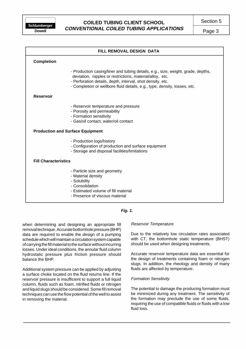
COILED TUBING CLIENT SCHOOLCONVENTIONAL COILED TUBING APPLICATIONS Page 3
Section 5Schlumberger
Dowell
FILL REMOVAL DESIGN DATA
Completion
- Production casing/liner and tubing details, e.g., size, weight, grade, depths,deviation, nipples or restrictions, material/alloy, etc.
- Perforation details, depth, interval, shot density, etc.- Completion or wellbore fluid details, e.g., type, density, losses, etc.
Reservoir
- Reservoir temperature and pressure- Porosity and permeability- Formation sensitivity- Gas/oil contact, water/oil contact
Production and Surface Equipment
- Production logs/history- Configuration of production and surface equipment- Storage and disposal facilities/limitations
Fill Characteristics
- Particle size and geometry- Material density- Solubility- Consolidation- Estimated volume of fill material- Presence of viscous material
Fig. 1.
Reservoir Temperature
Due to the relatively low circulation rates associatedwith CT, the bottomhole static temperature (BHST)should be used when designing treatments.
Accurate reservoir temperature data are essential forthe design of treatments containing foam or nitrogenslugs. In addition, the rheology and density of manyfluids are affected by temperature.
Formation Sensitivity
The potential to damage the producing formation mustbe minimized during any treatment. The sensitivity ofthe formation may preclude the use of some fluids,requiring the use of compatible fluids or fluids with a lowfluid loss.
when determining and designing an appropriate fillremoval technique. Accurate bottomhole pressure (BHP)data are required to enable the design of a pumpingschedule which will maintain a circulation system capableof carrying the fill material to the surface without incurringlosses. Under ideal conditions, the annular fluid columnhydrostatic pressure plus friction pressure shouldbalance the BHP.
Additional system pressure can be applied by adjustinga surface choke located on the fluid returns line. If thereservoir pressure is insufficient to support a full liquidcolumn, fluids such as foam, nitrified fluids or nitrogenand liquid slugs should be considered. Some fill removaltechniques can use the flow potential of the well to assistin removing the material.
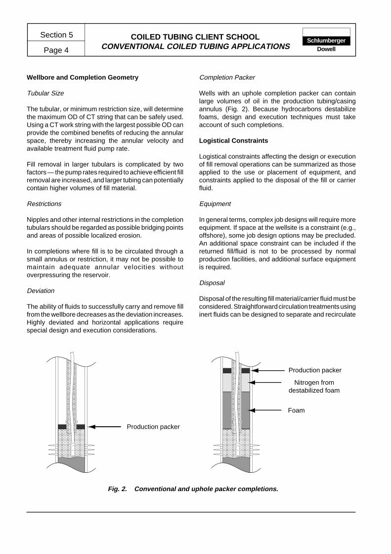
COILED TUBING CLIENT SCHOOLCONVENTIONAL COILED TUBING APPLICATIONS
Section 5
Page 4Schlumberger
Dowell
Wellbore and Completion Geometry
Tubular Size
The tubular, or minimum restriction size, will determinethe maximum OD of CT string that can be safely used.Using a CT work string with the largest possible OD canprovide the combined benefits of reducing the annularspace, thereby increasing the annular velocity andavailable treatment fluid pump rate.
Fill removal in larger tubulars is complicated by twofactors — the pump rates required to achieve efficient fillremoval are increased, and larger tubing can potentiallycontain higher volumes of fill material.
Restrictions
Nipples and other internal restrictions in the completiontubulars should be regarded as possible bridging pointsand areas of possible localized erosion.
In completions where fill is to be circulated through asmall annulus or restriction, it may not be possible tomaintain adequate annular velocities withoutoverpressuring the reservoir.
Deviation
The ability of fluids to successfully carry and remove fillfrom the wellbore decreases as the deviation increases.Highly deviated and horizontal applications requirespecial design and execution considerations.
Completion Packer
Wells with an uphole completion packer can containlarge volumes of oil in the production tubing/casingannulus (Fig. 2). Because hydrocarbons destabilizefoams, design and execution techniques must takeaccount of such completions.
Logistical Constraints
Logistical constraints affecting the design or executionof fill removal operations can be summarized as thoseapplied to the use or placement of equipment, andconstraints applied to the disposal of the fill or carrierfluid.
Equipment
In general terms, complex job designs will require moreequipment. If space at the wellsite is a constraint (e.g.,offshore), some job design options may be precluded.An additional space constraint can be included if thereturned fill/fluid is not to be processed by normalproduction facilities, and additional surface equipmentis required.
Disposal
Disposal of the resulting fill material/carrier fluid must beconsidered. Straightforward circulation treatments usinginert fluids can be designed to separate and recirculate
����������������������������������������������������������������������������������������������������
����������������������������������������������������������������������������������������������������
Fig. 2. Conventional and uphole packer completions.
Nitrogen fromdestabilized foam
Foam
Production packer
Production packer

COILED TUBING CLIENT SCHOOLCONVENTIONAL COILED TUBING APPLICATIONS Page 5
Section 5Schlumberger
Dowell
the carrier fluid to reduce the volumes required andminimize subsequent disposal. However, more complexjob designs including gelled fluids, foams and nitrogen/gel slugs can result in large volumes of fluid for disposal.
Certain types of fill or scale are classed as low specificactivity (LSA) radiation sources (e.g., strontium andbarium sulfates). Appropriate monitoring and protectionmeasures must be taken to ensure safe operations. Thelocal or national requirements or regulations associatedwith the processing and disposal of LSA solids must beknown to personnel designing and executing theoperation.
1.1.2 Fill Characteristics
To ensure the greatest efficiency of any fill removaloperation, the physical properties of the fill materialmust be known. A sample of material should be obtainedfor physical and chemical analyses. Samples of fillproduced from the reservoir formation can be obtainedfrom produced fluids or wireline sampling tools. If
possible, fill samples should be obtained from thewellbore for analyses. Samples obtained from producedfluids will contain particles which are more easilytransported (i.e., less dense and smaller particles) thanthe remaining wellbore fill. Samples of fill materialresulting from workover or stimulation activity should beeasily obtained from surface samples.
The conveying properties of most fill materials can beseverely affected by the presence of mud or other fluidswhich can cause a viscous mass.
Obtaining a sample of consolidated fill material may notbe possible. In such cases, the reservoir details and wellhistory should be closely studied to enable an accurateestimation of the fill properties. The fill characteristicsrequired for the job design include the particle size anddensity, solubility, and compressive strength.
STANDARD MESH/PARTICLE SIZE
U.S. Standard ParticleMesh Size Diameter (in.)
3 0.25004 0.18706 0.1320
8 0.093710 0.078712 0.0661
16 0.046920 0.033130 0.0232
35 0.019740 0.016550 0.0117
60 0.0098100 0.0059200 0.0029
270 0.0021325 0.0017
Fig. 3. U.S. Standard mesh/particle sizes.
TYPICAL WELLBORE FILL MATERIALPARTICLE SIZE AND DENSITY
Fill U.S. Standard DensityMaterial Mesh Size Range (SG)
Proppants
Sand 12 to 70 2.65Resin-Coated Sand 12 to 40 2.56ISP 12 to 40 3.20Sintered Bauxite 16 to 70 3.70Zirconium Oxide 20 to 40 3.15
Drilling/Workover Fluid Solids
Barite - 4.33Bentonite - 2.65Calcium Chloride - 1.75Sodium Chloride - 2.16Calcium Carbonate - 2.71
Wellbore Debris
Steel - 7.90Brass - 8.50Common Elastomers - 1.20
Formation Materials
Sand and Fines 100 to 350 2.65
Fig.4. Typical wellbore fill material particle size and density.
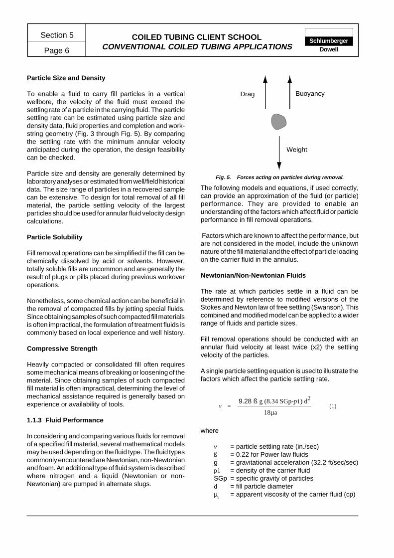
COILED TUBING CLIENT SCHOOLCONVENTIONAL COILED TUBING APPLICATIONS
Section 5
Page 6Schlumberger
Dowell
Particle Size and Density
To enable a fluid to carry fill particles in a verticalwellbore, the velocity of the fluid must exceed thesettling rate of a particle in the carrying fluid. The particlesettling rate can be estimated using particle size anddensity data, fluid properties and completion and work-string geometry (Fig. 3 through Fig. 5). By comparingthe settling rate with the minimum annular velocityanticipated during the operation, the design feasibilitycan be checked.
Particle size and density are generally determined bylaboratory analyses or estimated from well/field historicaldata. The size range of particles in a recovered samplecan be extensive. To design for total removal of all fillmaterial, the particle settling velocity of the largestparticles should be used for annular fluid velocity designcalculations.
Particle Solubility
Fill removal operations can be simplified if the fill can bechemically dissolved by acid or solvents. However,totally soluble fills are uncommon and are generally theresult of plugs or pills placed during previous workoveroperations.
Nonetheless, some chemical action can be beneficial inthe removal of compacted fills by jetting special fluids.Since obtaining samples of such compacted fill materialsis often impractical, the formulation of treatment fluids iscommonly based on local experience and well history.
Compressive Strength
Heavily compacted or consolidated fill often requiressome mechanical means of breaking or loosening of thematerial. Since obtaining samples of such compactedfill material is often impractical, determining the level ofmechanical assistance required is generally based onexperience or availability of tools.
1.1.3 Fluid Performance
In considering and comparing various fluids for removalof a specified fill material, several mathematical modelsmay be used depending on the fluid type. The fluid typescommonly encountered are Newtonian, non-Newtonianand foam. An additional type of fluid system is describedwhere nitrogen and a liquid (Newtonian or non-Newtonian) are pumped in alternate slugs.
Weight
BuoyancyDrag
Fig. 5. Forces acting on particles during removal.
The following models and equations, if used correctly,can provide an approximation of the fluid (or particle)performance. They are provided to enable anunderstanding of the factors which affect fluid or particleperformance in fill removal operations.
Factors which are known to affect the performance, butare not considered in the model, include the unknownnature of the fill material and the effect of particle loadingon the carrier fluid in the annulus.
Newtonian/Non-Newtonian Fluids
The rate at which particles settle in a fluid can bedetermined by reference to modified versions of theStokes and Newton law of free settling (Swanson). Thiscombined and modified model can be applied to a widerrange of fluids and particle sizes.
Fill removal operations should be conducted with anannular fluid velocity at least twice (x2) the settlingvelocity of the particles.
A single particle settling equation is used to illustrate thefactors which affect the particle settling rate.
9.28 ß g (8.34 SGp-p1) d2
18µav = (1)
where
v = particle settling rate (in./sec)ß = 0.22 for Power law fluidsg = gravitational acceleration (32.2 ft/sec/sec)p1 = density of the carrier fluidSGp = specific gravity of particlesd = fill particle diameterµ
a= apparent viscosity of the carrier fluid (cp)
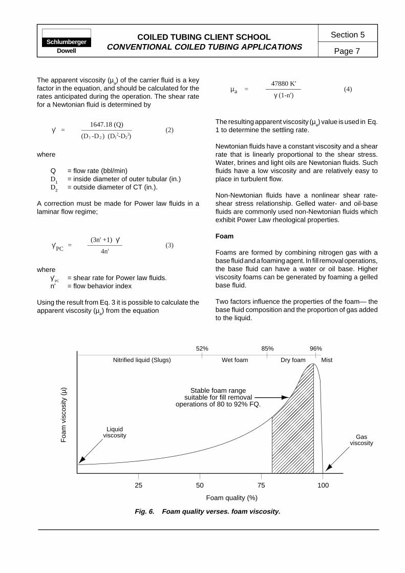
COILED TUBING CLIENT SCHOOLCONVENTIONAL COILED TUBING APPLICATIONS Page 7
Section 5Schlumberger
Dowell
47880 K'µ = (4)
γ (1-n')a
The resulting apparent viscosity (µa) value is used in Eq.
1 to determine the settling rate.
Newtonian fluids have a constant viscosity and a shearrate that is linearly proportional to the shear stress.Water, brines and light oils are Newtonian fluids. Suchfluids have a low viscosity and are relatively easy toplace in turbulent flow.
Non-Newtonian fluids have a nonlinear shear rate-shear stress relationship. Gelled water- and oil-basefluids are commonly used non-Newtonian fluids whichexhibit Power Law rheological properties.
Foam
Foams are formed by combining nitrogen gas with abase fluid and a foaming agent. In fill removal operations,the base fluid can have a water or oil base. Higherviscosity foams can be generated by foaming a gelledbase fluid.
Two factors influence the properties of the foam— thebase fluid composition and the proportion of gas addedto the liquid.
The apparent viscosity (µa) of the carrier fluid is a key
factor in the equation, and should be calculated for therates anticipated during the operation. The shear ratefor a Newtonian fluid is determined by
1647.18 (Q)γ' = (2)
(D -D ) 21 (D -D ) 2212
where
Q = flow rate (bbl/min)D
1= inside diameter of outer tubular (in.)
D2
= outside diameter of CT (in.).
A correction must be made for Power law fluids in alaminar flow regime;
(3n' +1) γ'γ' = (3)PC 4n'
whereγ’
PC= shear rate for Power law fluids.
n' = flow behavior index
Using the result from Eq. 3 it is possible to calculate theapparent viscosity (µ
a) from the equation
Fig. 6. Foam quality verses. foam viscosity.
��
����
�����
�����
�����
�����
����
@@
@@@@
@@@@@
@@@@@
@@@@@
@@@@@
@@@@
��
����
�����
�����
�����
�����
����
ÀÀ
ÀÀÀÀ
ÀÀÀÀÀ
ÀÀÀÀÀ
ÀÀÀÀÀ
ÀÀÀÀÀ
ÀÀÀÀ
��
����
�����
�����
�����
�����
����
@@
@@@@
@@@@@
@@@@@
@@@@@
@@@@@
@@@@
��
����
�����
�����
�����
�����
����
ÀÀ
ÀÀÀÀ
ÀÀÀÀÀ
ÀÀÀÀÀ
ÀÀÀÀÀ
ÀÀÀÀÀ
ÀÀÀÀ
��
����
�����
�����
�����
�����
����
@@
@@@@
@@@@@
@@@@@
@@@@@
@@@@@
@@@@
��
����
�����
�����
�����
�����
����
ÀÀ
ÀÀÀÀ
ÀÀÀÀÀ
ÀÀÀÀÀ
ÀÀÀÀÀ
ÀÀÀÀÀ
ÀÀÀÀ
��
����
�����
�����
�����
�����
����
@@
@@@@
@@@@@
@@@@@
@@@@@
@@@@@
@@@@
��
����
�����
�����
�����
�����
����
ÀÀ
ÀÀÀÀ
ÀÀÀÀÀ
ÀÀÀÀÀ
ÀÀÀÀÀ
ÀÀÀÀÀ
ÀÀÀÀ
��
����
�����
�����
�����
�����
����
25 50 75 100
Foam quality (%)
Foa
m v
isco
sity
(µ)
52% 85% 96%
Nitrified liquid (Slugs) Wet foam Dry foam Mist
Stable foam rangesuitable for fill removal
operations of 80 to 92% FQ.
Liquidviscosity Gas
viscosity
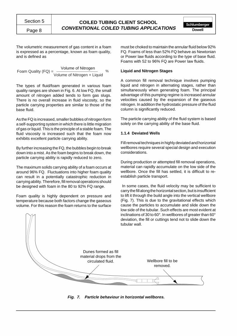
COILED TUBING CLIENT SCHOOLCONVENTIONAL COILED TUBING APPLICATIONS
Section 5
Page 8Schlumberger
Dowell
The volumetric measurement of gas content in a foamis expressed as a percentage, known as foam quality,and is defined as
Volume of NitrogenFoam Quality (FQ) =
Volume of Nitrogen + Liquid%
The types of fluid/foam generated in various foamquality ranges are shown in Fig. 6. At low FQ, the smallamount of nitrogen added tends to form gas slugs.There is no overall increase in fluid viscosity, so theparticle carrying properties are similar to those of thebase fluid.
As the FQ is increased, smaller bubbles of nitrogen forma self-supporting system in which there is little migrationof gas or liquid. This is the principle of a stable foam. Thefluid viscosity is increased such that the foam nowexhibits excellent particle carrying ability.
By further increasing the FQ, the bubbles begin to breakdown into a mist. As the foam begins to break down, theparticle carrying ability is rapidly reduced to zero.
The maximum solids carrying ability of a foam occurs ataround 96% FQ. Fluctuations into higher foam qualitycan result in a potentially catastrophic reduction incarrying ability. Therefore, fill removal operations shouldbe designed with foam in the 80 to 92% FQ range.
Foam quality is highly dependent on pressure andtemperature because both factors change the gaseousvolume. For this reason the foam returns to the surface
must be choked to maintain the annular fluid below 92%FQ. Foams of less than 52% FQ behave as Newtonianor Power law fluids according to the type of base fluid.Foams with 52 to 96% FQ are Power law fluids.
Liquid and Nitrogen Stages
A common fill removal technique involves pumpingliquid and nitrogen in alternating stages, rather thansimultaneously when generating foam. The principaladvantage of this pumping regime is increased annularvelocities caused by the expansion of the gaseousnitrogen. In addition the hydrostatic pressure of the fluidcolumn is significantly reduced.
The particle carrying ability of the fluid system is basedsolely on the carrying ability of the base fluid.
1.1.4 Deviated Wells
Fill removal techniques in highly deviated and horizontalwellbores require several special design and executionconsiderations.
During production or attempted fill removal operations,material can rapidly accumulate on the low side of thewellbore. Once the fill has settled, it is difficult to re-establish particle transport.
In some cases, the fluid velocity may be sufficient tocarry the fill along the horizontal section, but is insufficientto lift it through the build angle into the vertical wellbore(Fig. 7). This is due to the gravitational effects whichcause the particles to accumulate and slide down thelow side of the tubular. Such effects are most evident atinclinations of 30 to 60°. In wellbores of greater than 60°deviation, the fill or cuttings tend not to slide down thetubular wall.
Fig. 7. Particle behaviour in horizontal wellbores.
Dunes formed as fillmaterial drops from the
circulated fluid. Wellbore fill to beremoved.

COILED TUBING CLIENT SCHOOLCONVENTIONAL COILED TUBING APPLICATIONS Page 9
Section 5Schlumberger
Dowell
Studies have shown that hole cleaning in a horizontalwellbore is optimized when the fluid is in turbulent flow.However, in many cases, turbulent flow is not possibledue to the flow and pressure restrictions imposed by theCT work string, or the relative size of the completiontubular. In addition, turbulent flow is difficult to achieveover the length of a horizontal section where the CT isnon-centralized.
To compensate for the resulting laminar flow regimeand low annular velocity, the rheology of the fluid mustbe modified. Alternatively, in some cases, the annularvelocity can be maintained above the critical rate bypumping slugs of nitrogen and liquid. In such cases, theliquid selected should be capable of achieving turbulentflow at relatively low rates, i.e., Newtonian fluids.
1.1.5 Fluid Selection
Fluids used in the removal of wellbore fill material areselected following consideration of the following criteria:
• bottomhole pressure
• particle carrying ability
• friction pressure
• logistical constraints
• disposal
• compatibility
• cost.
Water/Brine
The general availability, low cost and generallystraightforward handling requirements of water andlight brines ensures their popularity as a basic fluid usedin most workover operations.
Water and light brines are commonly used as fill removalfluids in applications where the BHP and configurationof wellbore tubulars are suitable. In these cases theBHP is greater than the hydrostatic pressure exerted bythe fluid column, and the annular space is small enoughto ensure the high annular velocities required by suchfluids.
Newtonian fluids can be easily placed in turbulent flowwhich provides a useful scouring action. In addition,
Newtonian fluids generally provide the best jetting actionif compacted fill is to be removed.
Formation sensitivity and compatibility with wellborefluids should be checked prior to introducing aqueous-base fluid into the wellbore. Compatibility problems cangenerally be overcome by the use of stimulation fluidadditives.
Under static conditions these fluids exhibit no particlesuspension capabilities. Therefore, it is vital that anadequate annular fluid velocity is maintained throughoutthe operation.
Oil/Diesel
Light oils used in fill removal operations possessNewtonian fluid characteristics similar to those discussedfor water/brine. The most significant advantages of lightoil are improved compatibility and the reduction in fluiddensity, extending its suitability for operations in wellswith a lower BHP.
Operations associated with the handling and pumpingof flammable fluids require several safety, logistical andenvironmental concerns to be addressed. Personnelinvolved with the design or execution of flammable fluidoperations must be familiar with the requirements of theapplicable S&LP Standards.
Compatibility problems with oil-base fluid systems arelikely to be less restrictive than those of water-basesystems. However, compatibility should never beassumed, and basic laboratory compatibility tests shouldbe performed when possible.
Disposal of the carrier fluid is generally handled bynormal production facilities. However, separation of thefill material may require that fluids are rerouted totemporary separation/production facilities.
Separation and recirculation of flammable fluids aregenerally impractical for safety reasons. Consequently,larger volumes of fluid than would be necessary onrecirculated water-base systems are required.
Similar to water/brine, light oils exhibit no particlesuspension properties under static conditions. Therefore,it is vital that an adequate annular fluid velocity ismaintained for the duration of the operation.

COILED TUBING CLIENT SCHOOLCONVENTIONAL COILED TUBING APPLICATIONS
Section 5
Page 10Schlumberger
Dowell
Gelled Fluids
Water-base gels are the most common fill removal fluidused in applications which require improved particlecarrying and suspension ability.
The viscosity of gelled fluids is dependent on formulationand temperature. Therefore, it is important that the fluiddesign accurately reflects the anticipated wellboretemperatures, and the field mixing procedures closelyfollow the designed formulation. Variations in either ofthese factors from the designed system can result ingels with severely diminished particle carrying ability.
The additional fluid viscosity results in increased frictionpressures in the CT work string and annulus which canfurther restrict the pump rate. However, the improvedparticle carrying ability of gelled fluids adequatelycompensates for the reduction in annular velocity.
Several types of water-base gelling agents are commonlyused in fill removal operations, most of which arederived from stimulation/fracturing fluids. Formulationsand rheology data for most gel types are shown in theStimulation Manuals. However, laboratory tests shouldbe run to obtain rheology data for the designed gel at theapplicable temperature.
Oil-base gel fill removal fluids provide an improvedparticle carrying ability on application where oil-basefluids are preferred.
Liquid and Nitrogen Stages
Staged treatments are effective in several applicationswhere conventional fluid treatments are at the limit oftheir effectiveness.
• The CT/tubular annulus size is at the extreme range ofthe fluid's capability.
• The length of the CT work string limits the desiredpump rate due to friction pressure.
• The hydrostatic pressure exerted by a conventionalfluid column is too great.
• Foam is not a practical alternative.
The job design must result in a pumping schedule whichensures that the fill is penetrated only when liquids areat the nozzle. When N
2 is at the nozzle , the CT should
be stationary or withdrawn.
Foam
A good quality stable foam provides the best particlecarrying capability of any fluid. However, foam treatmentsare subject to more logistical and operational constraintsthan most other fill removal techniques. Provided a highdegree of backpressure control is exercised on annularreturns, foam may be used on a wide range of BHPconditions. Although foam treatments are closelyassociated with low and very low BHP treatments, thetechnique can be successfully applied to fill removal invery large tubulars.
The low fluid-loss properties of foam are of benefit inremoving fill from completions in high-permeabilityformations. Similarly, applications in water-sensitivereservoirs can be treated using special water-basefoams or oil-base foam. The operational cost associatedwith foam treatments, i.e., the additional nitrogenpumping equipment, is a disadvantage in applicationswhere the BHP and tubular sizes allow alternativetechniques to be used.
Foam is a poor jetting fluid and is unsuitable for manyapplications where the fill is compacted and requiressome jetting action to ensure complete removal.
Water-base foams are destroyed by hydrocarbons,consequently, treatments must be performed withoutreservoir fluids entering the wellbore. Hydrocarbonscontaminating the foam, even is small quantities, willresult in an unpredictable reduction in the carryingability of the foam.
The practical and environmental problems associatedwith breaking and disposing of the foam fluid depend onthe capability of the production or testing equipmentavailable at the wellsite.
To ensure that foam treatments are designed andexecuted efficiently relatively complex procedures mustbe carefully followed. In addition, treatment parametersmust be closely monitored to enable the treatment to bemodified to suit changing well conditions.
Stable foams can only exist in the foam qualities shownin Fig. 6. Stable foams are generated by creating auniform bubble size at the desired gas/liquid ratio. If thebubble size is nonuniform, liquid slugs can be easilyformed which tend to prematurely break the foam. Theconfiguration and geometry of a CT string on the reel willusually facilitate the generation of a good quality stablefoam. However, foam generating equipment may be

COILED TUBING CLIENT SCHOOLCONVENTIONAL COILED TUBING APPLICATIONS Page 11
Section 5Schlumberger
Dowell
required for use with larger size tubing strings (1-3/4 in.and greater).
An approximate measure of foam stability is foam half-life. The foam half-life of a foam is defined as the timerequired for 50% of the foam liquid to separate. However,such tests have poor reproducibility and the resultscannot be extrapolated to conditions other than thoseunder test.
To improve the stability of a foam, it is necessary toincrease the strength of the bubble walls. This is achievedby increasing the viscosity of the base liquid.
Nitrogen Gas
Fill removal operations using only gas as a transportmedium are applicable in low BHP or liquid-sensitivegas wells. Such applications generally use the productioncapability of the gas well to assist the nitrogen achievethe critical annular velocity required to initiate solidstransport. In such applications, erosion of the CT orcompletion equipment is a concern due to the highannular velocities required. An additional concern existsin that pumping operations must be uninterrupted.Interruption of the pump rate or even reducing theannular velocity below the critical level, will cause thesolids to immediately fall back. In this event, re-establishing solids transport is difficult and sticking ofthe CT string is likely.
1.1.6 Downhole Tools
The downhole tools referenced in this section are thosewhich may be required over and above the primary CTdownhole tools normally required (e.g., check valve/connector).
Small fill particles that are not compacted can usually besuccessfully removed by fluid action alone; therefore,mechanical assistance is generally not required.However, the exact nature of the fill material is often notknown before commencing the operation. Therefore, insome cases, it is desirable to use a tool string equippedto provide some mechanical assistance as a contingencymeasure.
Mechanical assistance during fill removal operationscan be provided by jetting tools, drill motors or impactdrills. Additional tools may also be required to supportthe operation (or provide contingency release) of thetool string.
Removal of very large particles or workover debriscontained within the fill may require the use of specializedfishing tools.
The following are some basic requirements of tools to beused in association with fill removal operations:
• The flow rate through the tool string should not berestricted below that required to provide the desiredannular velocity.
• Tools must be capable of operating in the high-solids-content annular fluid.
• The operation and components of the tool must becompatible with treatment fluids.
• The OD profile of the tool string should be as slim aspractical. In addition, the profile must not containsudden or large changes in OD which can inducesticking.
Jetting
Jetting provides a simple and effective aid in removingslightly compacted fill. Most applications are treatedwith low-pressure jetting through fixed nozzles or jettingsubs. Low-pressure jetting can generally be conductedwith a minimal effect on annular velocity. High-pressurejetting can be effective in removing compacted material;however, the high-pressure drop at the nozzle caneffectively reduce the flow rate below that required for asuitable annular velocity.
The jetting sub should be designed to provide goodjetting action and sufficient coverage of the tubular wall.Swirl or rotating nozzles can improve coverage andoptimize removal.
All forms of jetting have two main disadvantages - fullbore cleaning cannot be assured, and large cuttings canbe produced which cannot be transported by the annularfluid.
Drill Motor
Motors, bits and underreamers can be effective in thecomplete removal of compacted fill materials. However,the use of motors can be constrained by temperature,fluid type and cost.

COILED TUBING CLIENT SCHOOLCONVENTIONAL COILED TUBING APPLICATIONS
Section 5
Page 12Schlumberger
Dowell
Impact Drill
Impact drills are suited to a wide variety of fill removaloperations, which include the following advantages:
• The impact drill does not operate until resistance is metby the bit, allowing full circulation while running in thehole.
• A wide range of fluids may be used to power impactdrills.
• Impact drill assemblies are relatively short, facilitatingrig up and deployment.
• Impact drills are capable of operation at higher tem-peratures than conventional motors.
A significant disadvantage of impact drills is their inabilityto underream below a restriction.
Junk Removal
Wellbore fill that contains workover debris or largesolids (e.g., cement lumps) can require special fishingequipment. A variety of magnetic tools, junk basketsand custom- designed tools are used in such applications.If a wellbore is known or suspected of containing junk orparticles which cannot be removed by circulation, theBHA must be carefully chosen to reduce the risk ofsticking. In addition, an appropriate release tool must beincluded in the tool string. The risk of sticking the CT insuch applications can be high.
1.1.7 Tubing Movement
The rate of penetration during any fill removal operationis determined by the ability of the annular fluid to safelyremove the fill material. Loading of the annular fluid withfill material increases the hydrostatic pressure exertedby the annular column. In low BHP applications, thismay result in fluid being lost to the formation. Excessiveloading of the annular fluid can ultimately result insticking of the CT or tool string.
Estimates of penetration rates, tubing movement andcirculation times are required to enable fluid quantity,preparation and disposal needs to be planned, i.e., fluidrequirements are dependent on time in the wellbore,and time in the wellbore is determined by tubingmovement. To avoid the problems associated withexcessive penetration rates yet optimize the fill removaloperation, tubing movement must be closely aligned to
the pumping schedule. This is particularly importantwhile performing staged treatments, when only certainstage fluids are designed to carry the fill material.
The following guidelines on tubing movement andpenetration rates should be considered when designingfill removal operations.
Tagging Fill
In many cases the top of the fill will be known as a resultof a wireline survey. In such known conditions, the CTprogress to the fill and commencement of washing canquickly and efficiently be completed.
The fluid type and circulation rate will be determined bythe existing wellbore fluid, e.g., it may be desirable todisplace wellbore fluids as the CT is being run.
When the top of the fill is not known, several precautionsshould be taken to ensure that the CT is not run into apotential sticking situation. In many cases, loose fillmaterial can easily be penetrated with little or no indicationon the tubing weight indicator display. Slow circulationthrough the CT could be sufficient to penetrate the fill,yet be insufficient to transport the fill particles.
When performing fill removal operations in wellboreswhere the top and extent of fill are unknown, an assumedtop of fill point must be identified. When the CT reachesthis point, the CT penetration rate and pumping schedulemust be designed to be capable of safely removing thefill.
Penetrating Fill
The rate of fill penetration must never exceed the rate atwhich the maximum fluid loading occurs (Fig. 8). Thevalues shown are based on field experience in verticalwellbores and are conservative when compared withtheoretical examples. However, increased frictionpressure resulting from the fluid rheology changes willbe minimal below these levels.
During staged treatments (i.e., nitrogen/gelled fluid),penetration should only be attempted when the fluidsdesigned to carry the fill material are exiting the CTnozzle or tool. This requires that a detailed and accuratepumping schedule be prepared. To simplify the designand execution of such treatments, it is recommendedthat the stage volumes be related to the CT reel volume.
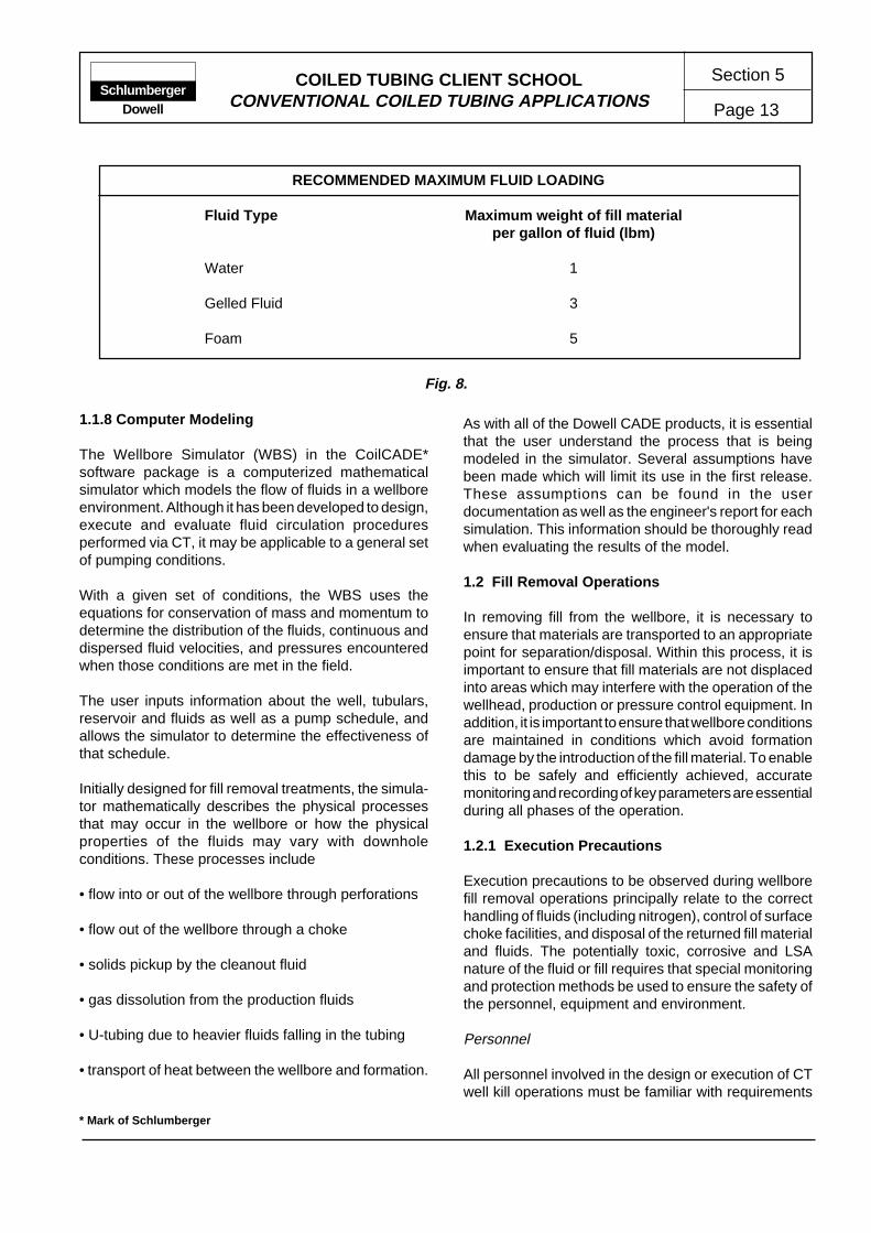
COILED TUBING CLIENT SCHOOLCONVENTIONAL COILED TUBING APPLICATIONS Page 13
Section 5Schlumberger
Dowell
1.1.8 Computer Modeling
The Wellbore Simulator (WBS) in the CoilCADE*software package is a computerized mathematicalsimulator which models the flow of fluids in a wellboreenvironment. Although it has been developed to design,execute and evaluate fluid circulation proceduresperformed via CT, it may be applicable to a general setof pumping conditions.
With a given set of conditions, the WBS uses theequations for conservation of mass and momentum todetermine the distribution of the fluids, continuous anddispersed fluid velocities, and pressures encounteredwhen those conditions are met in the field.
The user inputs information about the well, tubulars,reservoir and fluids as well as a pump schedule, andallows the simulator to determine the effectiveness ofthat schedule.
Initially designed for fill removal treatments, the simula-tor mathematically describes the physical processesthat may occur in the wellbore or how the physicalproperties of the fluids may vary with downholeconditions. These processes include
• flow into or out of the wellbore through perforations
• flow out of the wellbore through a choke
• solids pickup by the cleanout fluid
• gas dissolution from the production fluids
• U-tubing due to heavier fluids falling in the tubing
• transport of heat between the wellbore and formation.
As with all of the Dowell CADE products, it is essentialthat the user understand the process that is beingmodeled in the simulator. Several assumptions havebeen made which will limit its use in the first release.These assumptions can be found in the userdocumentation as well as the engineer's report for eachsimulation. This information should be thoroughly readwhen evaluating the results of the model.
1.2 Fill Removal Operations
In removing fill from the wellbore, it is necessary toensure that materials are transported to an appropriatepoint for separation/disposal. Within this process, it isimportant to ensure that fill materials are not displacedinto areas which may interfere with the operation of thewellhead, production or pressure control equipment. Inaddition, it is important to ensure that wellbore conditionsare maintained in conditions which avoid formationdamage by the introduction of the fill material. To enablethis to be safely and efficiently achieved, accuratemonitoring and recording of key parameters are essentialduring all phases of the operation.
1.2.1 Execution Precautions
Execution precautions to be observed during wellborefill removal operations principally relate to the correcthandling of fluids (including nitrogen), control of surfacechoke facilities, and disposal of the returned fill materialand fluids. The potentially toxic, corrosive and LSAnature of the fluid or fill requires that special monitoringand protection methods be used to ensure the safety ofthe personnel, equipment and environment.
Personnel
All personnel involved in the design or execution of CTwell kill operations must be familiar with requirements
Fig. 8.
RECOMMENDED MAXIMUM FLUID LOADING
Fluid Type Maximum weight of fill materialper gallon of fluid (lbm)
Water 1
Gelled Fluid 3
Foam 5
* Mark of Schlumberger
COILED TUBING CLIENT SCHOOLCONVENTIONAL COILED TUBING APPLICATIONS
Section 5
Page 14Schlumberger
Dowell
detailed in the relevant S&LP Standards. In addition, therequirements for the handling and disposal of LSAmaterials must be known. Monitoring and protectioncriteria should be defined in association with the operatingcompany or designated third party.
Well Security
The control of well pressure and fluids must meet therequirements of relevant S&LP Standards. In additionthe requirements of the operating company andapplicable regulatory authorities must be known.
Equipment
All Dowell treating and monitoring equipment must bespotted and operated in accordance with therequirements of the relevant S&LP Standards. In addition,equipment certified for use in hazardous area must beoperated and maintained in accordance with theoperating zone requirements (e.g., Zone II equipment).
1.2.2 Equipment Requirements
Operations that involve the circulation of particulatematerial from the wellbore must be carefully plannedand executed. The consequences of stopping or losingcirculation while the annular fluid is laden with solids canbe severe. Therefore, adequate precautions must betaken to ensure that the operation proceeds as planned.A typical equipment schematic for fill removal operationsis shown in Fig. 9.
Coiled Tubing Equipment
Fill removal operations frequently require the tool stringto be repeatedly cycled over a localized area. In thisevent, consideration must be given to the effects ofinducing fatigue in the corresponding localized area ofthe work string as it passes the reel and gooseneck. Inaddition, the effect of fatigue while conducting high-pressure jetting operations must be accurately predicted.Cycling the work string under high internal pressuresdrastically reduces the useful life of the work string.
Pressure Control Equipment
The configuration of CT pressure control equipmentallows fill removal operations to be completed safelyand efficiently under live well conditions. The equipmentmust be configured to avoid circulating corrosive orsolids-laden annular return fluid through the BOP.However, in certain cases, it may be necessary to return
fluids through a shear/seal BOP installed above thetree. Returns should then be taken through a pump-intee installed in the riser.
Downhole Tools and Equipment
Jetting Assemblies
Jetting tools should be configured to maximize theavailable fluid rate and pressure. In addition to improvingthe efficiency of consolidated fill removal, this will ensurethe circulation rate is maximized to aid fill dispersion andremoval of solids from the wellbore.
Drill Motor Assemblies
Drill motor assemblies should be function tested beforerunning in the hole. Typically, this is achieved after theassembly has been made up to the work string and ishanging inside the lubricator/riser. This should beconsidered a basic operational check. Morecomprehensive checks, including the motor torque,must be completed prior to rigging up.
Impact Drill Assemblies
Impact drill assemblies should be function tested beforerunning in the hole. Impact drills do not operate until thetool is pushed into the collapsed position; therefore, thetoolstring has to be manipulated during the testprocedure.
Typically, the function test is performed after the toolstring has been assembled and attached to the workstring, and circulation has been established. The tool iscollapsed and tested by placing the bit on a firm woodensurface by carefully controlling injector head.
Auxiliary Equipment
The fluid mixing, handling and pumping equipment mustbe of adequate capacity and be configured to minimizecross contamination of the fluid stages.
Live well operations may require the use of a chokemanifold to control annular returns. In this event, a clearline of communication must exist between the CTU,pump and choke manifold operators.

COILED TUBING CLIENT SCHOOLCONVENTIONAL COILED TUBING APPLICATIONS Page 15
Section 5Schlumberger
Dowell
Nitrogen/foamgenerationpackage
Sample point
Disposal
Process andrecirculate
BOP kill port
Chokemanifold
Pumping teebelow
pressurecontrol
equipment
Fig. 9. Typical foam equipment configuration for fill removal.
CT nozzle/tools
Productiontubing
1.2.3 Treatment Execution
The steps required to successfully complete a fill removaloperation will depend on the particular conditionsencountered in each case. In the following section, thekey points in each phase of the operation are outlined.When preparing and documenting a treatmentprocedure, it is recommended that the key points bereviewed (with the applicable points being incorporatedinto the job procedure as required).
Wellbore fill removal treatments are frequently designedand conducted on a regular basis within a field or area.Consequently, procedures are often tuned to meet local
conditions by application of the DESIGN EXECUTEEVALUATE* cycle. Whenever possible, previous casehistories for similar applications should be referenced.
Execution of wellbore fill and scale removal treatmentsare accomplished in two basic steps:
• wellbore preparation
• treatment and tool operation

COILED TUBING CLIENT SCHOOLCONVENTIONAL COILED TUBING APPLICATIONS
Section 5
Page 16Schlumberger
Dowell
Wellbore Preparation
• The recovery of wellbore samples for analysis can becompleted by CT conveyed tools in conjunction withpreparatory work. Typically, slick-line methods areused; however, in deviated or logistically difficultconditions, CT may be used.
• If it is desired to remove completion equipment compo-nents such as gas-lift valves or safety valves, the useof CT conveyed methods should be considered. Insome cases, the fill or scale condition to be treated willhamper retrieval of downhole devices. Tools andtechniques used in CT conveyed methods will allowthe circulation of treatment fluids to facilitate removal.In addition, the forces which may be exerted by CT aregreater than commonly used wireline equipment.
• It may be necessary to kill the well for safety, fluidcompatibility or production reasons. In such wellboreswith known fill or deposits, it is clearly undesirable torisk damaging the near wellbore area by bullheadingthe wellbore fluid. Coiled tubing well kill techniquescan be used to minimize the potential of damageduring the well kill process.
Treatment and Tool Operation
• The volume and density of all fluids pumped into thewellbore must be monitored and recorded.
• Since full bore cleaning cannot be assured, a numberof passes should be made over any consolidated fillarea. The procedure will be determined by experiencein similar conditions and fill material characteristics.
• Use the largest feasible size of work string to allowhigher circulation rates and higher annular velocity.
• The operational efficiency of impact drills is greatlydependent on applying the appropriate weight at thetool. The use of a suitable accelerator can simplify theprocess; however, a high degree of injector-headcontrol is necessary. This control is based on weightindicator readings; therefore, the weight indicatorsystem must be properly operated and maintained.
1.3 Fill Removal Evaluation
The requirements of the operator will ultimately determinethe extent to which the fill material must be removed andwhat means are to be used to evaluate the success ofthe operation.
Solids removal operations are generally evaluated byperforming a drift run. Typically, a slick-line gauge-cutter tool will be run, although CT conveyed methodsmay also be used.

COILED TUBING CLIENT SCHOOLCONVENTIONAL COILED TUBING APPLICATIONS Page 17
Section 5Schlumberger
Dowell
2 MATRIX STIMULATION
When a well does not, or can no longer, produce at therates expected, the formation may be “damaged.” Bycarefully evaluating the wellbore and reservoirparameters, the type and degree of damage can beidentified. If the reservoir permeability is low, the wellmay be a candidate for hydraulic fracturing. However, ifnear-wellbore damage is found to be reducing wellproductivity, matrix stimulation may be appropriate. Inaddition to offering economic advantages over hydraulicfracturing, matrix treatments are preferred whenfracturing may result in the undesirable production ofgas or water.
Various types of damage exist, several of which maycoexist, because almost every operation performed ona well (drilling, completion, production, workover andstimulation) is a potential source of damage. The mostcommon form of damage is plugging of the formationaround the wellbore.
Stimulation treatments must either remove the damage(in sandstones) or create channels to bypass thedamaged zone (in carbonates). Such matrix stimulationtreatments are designed to restore the naturalpermeability of the formation by injecting treatmentfluids at a pressure less than the formation fracturepressure.
Coiled tubing is commonly used to perform matrixtreatments, and in many cases will offer severaladvantages over conventional treatment techniques.
• The CT pressure control equipment configurationallows the treatment to be performed on a live well.The potential formation damage associated with wellkilling operations and the corresponding loss ofproduction time are thereby avoided.
• Associated operations can be performed as part of anintegrated service, e.g., wellbore fill can be removedprior to the matrix treatment and nitrogen or artificial liftservices may be applied to restore production followingthe treatment if required.
• Performing the treatment through CT avoids exposingthe wellhead or completion tubulars to direct contactwith corrosive treatment fluids.
• Spotting the treatment fluid with CT will help ensurecomplete coverage of the interval. This in conjunctionwith an appropriate diversion technique will help ensure
uniform injection of fluid into the target zone. Spottingthe treatment fluid also avoids the need to bullheadwellbore fluids into the formation ahead of the treatment.
• Long intervals can be more effectively treated usingtechniques and tools that have been developed foruse with CT, e.g., FoamMAT* foam diversion or aselective treatment system using straddle-pack isola-tion tools. This particularly important in horizontalwellbores.
By recognizing the limitations of the CT and associatedequipment, treatments can be designed to achieve themaximum benefit to the zone while operating within safelimits and approved techniques. For example, therelatively high friction pressures and low pump ratesassociated with CT can extend the duration of largevolume treatments beyond viable limits. In many cases,a lower volume treatment selectively applied will achievesimilar, or better, results.
2.1 DESIGN
The following general guidelines outline the principalconsiderations when designing and executing matrixtreatments. While most of the points listed will apply toany matrix treatment, some emphasis is made onconsiderations which apply to operations performedthrough CT.
• Ensure that the well is a candidate for matrix stimulationby confirming the presence of damage.
• Identify the location, composition and origin of thedamage.
• Gather and compile the wellbore and completioninformation required for job design and evaluation oftreatment options.
• Select an appropriate treatment fluid, including additivesand associated treatments. Conduct compatibility teststo ensure there are no adverse reactions betweenfluids.
• Determine the maximum injection rate and pressure.
• Determine the treatment volume.
• Consider the use of diverting agents to help ensurecomplete coverage.
• Consider the use of selective treatment tools.
* Mark of Schlumberger

COILED TUBING CLIENT SCHOOLCONVENTIONAL COILED TUBING APPLICATIONS
Section 5
Page 18Schlumberger
Dowell
MATRIX TREATMENT DESIGN DATA
Drilling - Drilling mud details over zone of interest, e.g., type, density, losses, unusual conditions, etc.- Casing/liner cementing details for zone of interest, e.g., type, density, losses, evaluation, unusual conditions, etc.
Completion - Production casing/liner and tubing details, e.g., size, weight, grade, depths, deviation, nipples or restrictions, material/alloy, etc.
- Perforation details, depth, interval, shot density, etc.- Completion fluid details, e.g., type, density, losses, etc.
Reservoir - Formation analysis.- Reservoir temperature and pressure.- Porosity and permeability.- Gas/oil contact, water/oil contact.
Production - Production test results, e.g., skin, effective permeability, production rates, etc.- Production logs/history.- Results of NODAL* analysis
Workover - Details of previous stimulation or remedial treatments.
Laboratory Analyses
- Acid solubility- Formation water analysis- Emulsion and sludge testing- Iron content testing- Permeability and porosity- Flow test (ARC)- SEM/ Edax studies- Petrographic studies- Determine paraffin/asphaltine content.
Fig. 10.
• Prepare a complete pumping schedule, including shut-in and flowback requirements.
• Forecast the economic viability of the treatment.
The importance of obtaining adequate, and accurate,wellbore and reservoir data prior to designing stimulationtreatments cannot be understated. This is necessary forseveral reasons:
• By confirming the composition, location and degree ofdamage, the selection of an appropriate treatmentfluid is possible.
• The maximum cost effectiveness of the treatment canonly be ensured if all aspects of the treatment areoptimized.
• By conducting pre- and posttreatment tests and com-parisons, the efficiency of the treatment may be quan-tified.
In addition to reservoir and wellbore parameters, theselection of an appropriate treatment may be dependenton the well or field production objectives and economics.

COILED TUBING CLIENT SCHOOLCONVENTIONAL COILED TUBING APPLICATIONS Page 19
Section 5Schlumberger
Dowell
2.1.1 Candidate Selection
When a well has been identified as a possible candidatefor matrix treatment, it is necessary to gather andcompile data for analyses and design purposes. Fig. 10summarizes the typical fields of data required for matrixtreatment design. This should be regarded as a basicguide list which may require additional input for complexjob designs or procedures.
Formation Damage
The objective of a matrix treatment is to remove thedamage which impairs the productivity of the well, i.e.,decrease skin. Therefore, it is essential to know thetype, amount, location and origin of the damage.
The presence and amount of damage are calculatedfrom data obtained by conducting a pressure transientanalysis, i.e., by pressure buildup or drawdown tests.Such tests provide invaluable information to optimizethe treatment and evaluate the results.
The type, location and origin of the damage aredetermined by reviewing the results of the pressuretransient analyses in conjunction with the informationoutlined in Fig. 10.
Damage can be characterized by two importantparameters - its composition and location. The locationsof various damage types are summarized in Fig. 11.
Wellbore and Completion Characteristics
A key factor in determining the suitability of CT in anyoperation is the ability to safely run and retrieve the CTinto and out of the wellbore. The size of completiontubulars and placement of restrictions will initiallydetermine if CT can be used to convey the treatmentfluid or tools.
In highly deviated and horizontal wellbores, deviationsurvey data are required, in addition to completiongeometry, as input for the CoilCADE* Tubing ForcesModel (TFM). The TFM may then be used to determinehow far the CT may be pushed into the wellbore. Inaddition, the anticipated forces are calculated for runningand retrieving the CT.
Well Preparation
There are several options available when selecting atreatment technique. For example, the entire treatmentmay be performed through CT, or the CT may be usedto prepare the wellbore and spot the treatment fluid
Fig. 11.
TYPE AND LOCATION OF COMMON FORMATION DAMAGE
Damage Location
Tubing Gravel Pack Perforations FormationType of Damage
Scales x x x x
Organic Deposits x x x x
Silicates, Aluminosilicates x x x
Emulsion x x x
Water Block x
Wettability Change x
Bacteria x x x x
* Mark of Schlumberger
COILED TUBING CLIENT SCHOOLCONVENTIONAL COILED TUBING APPLICATIONS
Section 5
Page 20Schlumberger
Dowell
inside the production tubing. Regardless of the techniqueemployed, it is undesirable to inject damaging fluids,scales or other wellbore solids into the formation. Designconsideration must be given to the removal of thefollowing potential damage sources before conductingthe main treatment:
• wellbore fill material near the treatment zone (seeWellbore Fill Removal)
• scale, asphalt or solids in the production tubing/liner
• rust and scale deposits inside the CT work string.
The Dowell Tubeclean Service uses a fluid containinginhibited acid, solvents, iron reducing agents and solidssuspending agents to clean tubulars before stimulationand sand control treatments. In addition to removingdamaging solids, the Tubeclean treatment prevents themain treating fluid from carrying high concentrations ofdissolved iron into the formation.
2.1.2 Treatment Fluid
Selection of an appropriate treatment fluid is determinedby the type of damage and its location. The location ofthe damage is a significant consideration because thetreatment fluid may contact several other substratesbefore contacting the damaged zone, e.g., rust or scaleon well tubulars or carbonate cementing materials. Thefluid must then provide an effective treatment on contactwith the damaged zone.
In most cases, the exact type of damage cannot beidentified with absolute certainty. In addition, there isoften more than one type of damage present. Therefore,many stimulation treatments incorporate fluids to removemore than one type of damage.
Selection of the most appropriate treatment fluid andadditives for given wellbore and reservoir conditionsshould be made by following guidelines given in thereference documents listed in Section 5.
The following list summarizes the criteria consideredwhen selecting treatment fluids for use with CT:
• Physical characteristics of the damage. These charac-teristics will often determine the nature of the basetreatment fluid, e.g., acid- or solvent-base treatment.
• Reaction of the treatment fluid with the formation.Adverse reactions between the formation and treating
fluid can create new damage and compound existingproductivity problems. Such potential reactions arecontrolled by additives in the treatment fluid and bypreflush and overflush treatments.
• Prevention of excessive corrosion, both to CT andcompletion equipment (see subsection 2.5.1 CorrosionInhibitor).
• Use of friction reducers to optimize the treatment rate(seesubsection 2.4.2 Friction Reducer).
• Compatibility of treatment fluid with wellbore andreservoir fluids. Fluid additives are used to preventsludge or emulsions, disperse paraffins and preventprecipitation of reaction products.
• Compatibility of treatment fluid with diverting agent(see subsection 2.5 Diversion).
• Cleanup and flowback. Using CT to perform a matrixtreatment provides the means to quickly initiate pro-duction following treatment. If the reservoir pressurecannot overcome the hydrostatic pressure exerted bythe spent treatment fluid, nitrogen kickoff techniquesmay be performed. As an alternative, energizing thetreatment fluid may be appropriate.
Preflush/Overflush
Some treatments, especially in sandstone reservoirs,require preflush and overflush fluids to prevent adversesecondary reactions and the creation of precipitatesfrom the treatment fluid.
The preflush provides separation between the connatewater and treatment fluid and, in sandstone treatments,reacts with carbonate minerals in the formation to preventtheir reaction with the hydrofloric acid (HF). Brine,solvent or hydrochloric acid (HCl) can be use as preflushfluids.
The primary purpose of an overflush is to displacepotentially damaging precipitates deep into the reservoir,away from the wellbore. Special overflushes can beformulated to facilitate diverter cleanup. Ammoniumchloride brine, HCl (3 to 10%) and light hydrocarbons(e.g., diesel) are commonly used as overflush fluids.
The volume of preflush or overflush required is calculatedon the basis of the radial displacement required.

COILED TUBING CLIENT SCHOOLCONVENTIONAL COILED TUBING APPLICATIONS Page 21
Section 5Schlumberger
Dowell
2.1.3 Fluid Additives
While the base treatment fluid is designed to remove thedamage, most treatments require the use of additives toimprove reactions and control potential damage to theformation, completion tubulars or CT work string. Thefollowing types of additive are commonly used on matrixstimulation treatments:
• Acid corrosion inhibitors are required on all jobs toreduce the rate of corrosion on treating and completionequipment to an acceptable level.
• Alcohol is often used in gas wells to lower surface/interfacial tension, increase vapor pressure and im-prove cleanup.
• Antifoam agents prevent excess foam from beingformed when mixing fluids on the surface.
• Clay stabilizers are used to prevent damage from thedispersion, migration or swelling of clay particles.
• Diverting agents help ensure complete coverage of thezone to be treated.
• Formation cleaner will kill and remove bacteria andpolymer residues.
• Iron stabilizers are used to prevent the precipitation ofgelatinous ferric iron in the formation.
• Mutual solvents serve as a wetting agent, demulsifiersand surface/interfacial tension reducer.
• Organic dispersants and inhibitors are used to removeand inhibit the deposition of organic materials.
• Surfactants have several functions and uses whichmay be summarized as aiding the penetration of fluidsthrough the formation during treatment and flowback.
Many of the additives commonly used in stimulationtreatments will present a hazard to personnel and theenvironment if handled incorrectly. Consideration mustbe given to the safe handling, mixing, cleanup anddisposal of treatment fluids and additives.
A more detailed description and explanation of fluidadditives crucial to CT operations follows. Further detailson range and selection of other fluid additives may befound in the references listed in Section 5.
Corrosion Inhibitors
The useful life and reliability of a CT work string aregoverned by the effects of fatigue and corrosion.Therefore, ensuring adequate corrosion control is anobvious requirement when designing stimulationtreatments performed through CT.
In common with all stimulation fluid additives, corrosioninhibitors must perform their principal function withoutaffecting the injectivity or productivity of the treatedformation. Several compounds provide excellentcorrosion protection but can cause significant formationdamage.The range of corrosion inhibitors and inhibitoraids developed by Dowell is formulated to provideoptimum inhibition performance without damaging theformation.
The addition of certain materials to the acid system(such as surfactants, mutual solvents, demulsifiers andnon-emulsifiers) can alter the temperature range inwhich an inhibitor may be considered effective. In severecases, the inhibitor may be rendered ineffective at thedesired treatment temperature.
The stresses to which a CT work string is subjected asit is plasticly deformed require some considerationwhen selecting corrosion inhibitor schedules for CTconveyed treatments. In addition, the extremely highfluid velocities encountered inside the CT means ahigher concentration of corrosion inhibitor is required toprovide the necessary protection.
The efficiency of pumping a small high-concentrationcorrosion inhibitor slug ahead of the treatment fluid isinconclusive and cannot substitute for a well-designedand prepared inhibitor schedule. However, it is generallyaccepted that an inhibitor slug ensures good initialprotection for the work string. The efficiency of such atreatment is improved when all rust or scale inside theCT is removed by pickling the work string prior to thetreatment.
The performance of most corrosion inhibitors issignificantly reduced in the presence of H
2S. To overcome
these effects, an H2S scavenger (e.g., M187) should be
used. Increasing the concentration of corrosion inhibitoris ineffective.

COILED TUBING CLIENT SCHOOLCONVENTIONAL COILED TUBING APPLICATIONS
Section 5
Page 22Schlumberger
Dowell
CORROSION INHIBITOR AND INHIBITOR AID SELECTION
Corrosion Inhibitors Remarks
A166 Low-temperature inhibitor up to 310°F. Not recommended if acid systemsincorporate large additive packages. Use appropriate inhibitor aid atsuggested temperature ranges.
A186 Organic acid inhibitor. Does not require inhibitor aids.
A250 General use inhibitor up to 300°F. Use Inhibitor Aid A201 above 220°F.
A252 High-temperature inhibitor (<350°F) requires A201 above 250°F.
A260 Temperature range up to 300°F. Effective with large additive packages.Requires Inhibitor Aid A153 if temperature is under 240°F. If temperature isover 240°F, use A201.
A270 High-temperature inhibitor designed for temperatures above 275°F although it is effective at lower temperatures. Use with A201.
Inhibitor Aids
A153 Enhances efficiency of inhibitor. Minimizes pitting tendencies below 240°F.
A179 Preferred inhibitor aid when acid system contains Methanol K46.
A201 General use inhibitor aid. Ineffective at temperatures below 220°F.
Fig. 12.
The selection of an appropriate corrosion inhibitor (typeand concentration) can be done only after specificationof the following treating and well conditions:
• type and concentration of acid
• maximum temperature
• duration of acid contact
• type of tubular/completion goods which will be exposed
• presence of H2S.
The effective range of corrosion inhibitors can beextended and improved by using inhibitor aids. A list ofcorrosion inhibitors and inhibitor aids commonly usedwith CT conveyed treatments is shown in Fig 12.
H2S Protection
The presence of H2S affects the design and execution
of matrix stimulation jobs in several ways:
• Because H2S is frequently liberated as an acid reaction
product, the well condition must be considered sourfollowing treatment and during cleanup. Personneland equipment safety requirements must be observedduring these periods.
• Wells with a sour status must be treated using CTdownhole tools and equipment that can be positivelyidentified as suitable for H
2S service.
• The efficiency of some additives, especially corrosioninhibitors, can be significantly reduced in the presenceof H
2S.

COILED TUBING CLIENT SCHOOLCONVENTIONAL COILED TUBING APPLICATIONS Page 23
Section 5Schlumberger
Dowell
Protection against the effects of H2S can be achieved by
using a scavenger (e.g., M187or A255). In most cases,H
2S protection should be applied to the exterior surface
of the CT as well as included in the treatment fluid.
Friction Reducers
The efficiency of many treatments can be significantlyimproved by increasing the rate at which the treatmentfluid enters the formation. The pump rate of treatmentsperformed through CT is limited by the restricted internaldiameter and length of the work string, i.e., fluids mustbe pumped through the total string length, regardless ofthe depth of the treatment. Using a friction reducingagent can significantly increase the rate at which fluidsmay be pumped. In addition to improving the treatmentefficiency, the job time will be reduced. Such a reductionin job time may be an important consideration in largevolume treatments.
2.1.4 Injection Pressure and Rate
The design of matrix acid treatments should not onlyspecify the volumes and types of fluid to be injected, butalso the maximum permissible injection rate and treatingpressure, to avoid fracturing the formation.
Downhole Sensor Package
The downhole sensor package (DSP*) is a real-timedownhole data acquisition system which can be used tomonitor temperature, pressure and casing collar data.Real-time bottomhole pressure (BHP) and temperature(BHT) data acquired during a matrix treatment can beused to determine the efficiency of the stimulation as itprogresses. This capability provides several benefitscontributing to the optimization of the treatment:
• Accurate BHP and BHT data for any well profile. TheDSP package has potential for virtually every oilfieldCT application anytime it is desirable to have accuratereal-time knowledge of the BHP and BHT during a CToperation. This includes vertical, inclined and horizontalwellbores, cased and open hole.
• Evaluate-Treat-Evaluate– Conventional static pressurebuild up and pressure drawdown flow testing is easilydone using the DSP package. Well test data collectedby the system and sent to the laptop can be processedon location to allow for last minute changes in atreatment design if necessary. Pressure buildup testsrun before and after an acid or other formation damageremoval treatment can be used to evaluate changes in
effective permeability, skin damage and well produc-tivity. The BHP during matrix treatments can be usedby MatTIME* software to calculate skin.
• Optimized diversion–Use of the DSP package allowsfor real-time knowledge of the actual BHP, regardlessof fluctuations in the circulating rate, foam quality,hydrostatic head or friction pressure. If necessary, itallows for changes to be made to the treatment scheduleas the job is being pumped. For example, while a foamdiversion stage is being pumped, the BHP continuesto decrease instead of increase; the foam stage can becontinued until the BHP sufficiently increases to indicatethat diversion is taking place.
2.1.5 Treatment Volume
The treatment volume (gal/ft of perforated interval) ismost commonly determined by field experience, althoughlaboratory tests can be conducted if no history exists.The amount of acid required to remove formation damageis dependent on many factors relating to thecharacteristics of the damage, formation and treatmentfluid.
The objective of establishing the treatment volume is toachieve an acceptable permeability increase. Increasingthe treatment fluid volume in an attempt to remove alldamage is costly and carries the risk of further formationdamage. For example, in sandstone formations,excessive removal of the cementing material can resultin the deconsolidation and collapse of the formation.
2.1.6 Diversion
Successful matrix treatments depend on the uniformdistribution of the treating fluid over the entire production(or injection) interval. When fluids are pumped into awell, they naturally tend to flow into the zones with thehighest permeability and least damage. By diverting theflow of treatment fluid to the areas of lesser permeability,a more effective treatment will be achieved. Productionlog data can be used to identify high-permeability zonesor thief zones, enabling the design of an efficientplacement/diversion technique.
The criteria for selection of a diversion technique oragent include the following:
• The diverting agent must provide uniform distributionof treating fluid into zones of widely differentpermeability.
* Mark of Schlumberger
COILED TUBING CLIENT SCHOOLCONVENTIONAL COILED TUBING APPLICATIONS
Section 5
Page 24Schlumberger
Dowell
• The diverter must not cause permanent damage to theformation.
• A rapid and complete cleanup must be possible toavoid secondary damage from precipitates.
• The diversion agent must be compatible with thetreating fluid, additives and overflush or displacementfluids.
• The diverter must be effective at the applicable treatmenttemperature.
Diverting techniques can be classified as mechanical,chemical or foam. In addition, although not a truediversion technique, reciprocating the CT nozzle overthe treatment zone during the treatment can be beneficialin some operations. Reciprocating the CT can assist intreatments intended to remove possible damage in oraround the perforation tunnels. An appropriate jettingnozzle reciprocated over the interval while pumping thefluid will help clean the perforation tunnels and improvethe treatment.
One of the greatest advantages of performing treatmentsthrough CT is the ability to continuously pump fluidswhile moving the tubing and nozzle. However, aconsequence of reciprocating the string under highinternal pressure is the increased fatigue that can beinduced in a relatively short interval of the work string.The benefits of such techniques must be weighedagainst the reduced life of the CT string and localizedfatigue.
In almost all cases, the ability to spot the treatment fluidover the entire treatment zone before injection will bebeneficial.
Mechanical Diversion
Mechanical diversion methods applicable to CT matrixtreatments are limited to techniques incorporating bridgeplugs, packers and straddle packers. Conventionalmethods of diversion using ball sealers are not compatiblewith CT conveyed treatments because of the restrictedinternal diameter and low pump rates associated withCT.
The use of packers and plugs to isolate and selectivelytreat zones can be desirable because the treatment iseffectively conducted on a shorter zone. Within thisshort zone, the need for diversion during the treatmentis less critical and successful treatments can beperformed using conventional fluids.
A straddle packer configuration is preferred becausethe forces created by the injection pressure are balanced,enabling a secure and efficient packer seal. The distancebetween the two packers is adjustable, using a range ofspacers, when the tool is assembled (Fig 13).
The following points must be considered when designinga matrix treatment in conjunction with a packer toolstring.
• The maximum spacer length (i.e., treatment interval) islimited by the maximum tool length that can be safelydeployed into and out of the well.
• The maximum injection pressure is determined by thespecifications and expansion of the packers.
• All fluids must be free of particulate solid which couldblock restricted passages within the tool string.
• Circulation through the work string while the toolstringis being run and retrieved is not possible. Pumpedfluids will cause the packer elements to inflate, therebyincreasing the risk of damaging the packer or surgingor swabbing the wellbore.
Chemical Diversion
Many chemical compounds have been used as divertingagents. However, because cleanup problems wereencountered in numerous cases, only a few are nowcommonly used. Most chemical diverters function byforming a bridge or cake of lower permeability on theformation face to create an artificial skin. This solublecake is dissolved and removed during cleanup andsubsequent production (or injection).
High-viscosity fluids can also be used as divertingagents but are more commonly used to plug waterzones when acidizing adjacent oil zones or in horizontalwellbores. The use of self diverting acid (SDA) systemsis increasingly effective in carbonate formations. In suchacid systems the fluid crosslinks to provide a highviscosity as it spends. When completely spent ituncrosslinks and can be easily flowed back.
The efficiency of chemical diversion techniques isimproved with higher injection or treating rates. Becausea limitation of CT conveyed treatments is the relativelylow circulation rate, certain chemical diverting agentsmay be unsuitable in low pump-rate applications. Inaddition, large particulate solids can plug or interferewith the operation of downhole tools (e.g., check valves)required on CT operations.

COILED TUBING CLIENT SCHOOLCONVENTIONAL COILED TUBING APPLICATIONS Page 25
Section 5Schlumberger
Dowell
An appropriate chemical diverting agent must meetseveral physical and chemical requirements:
• Permeability – The bridge or cake formed on theformation face should be as impermeable as possibleto achieve maximum diversion. If the permeability ofthe cake is greater than that of the tightest zone, littleor no diversion will occur.
• Invasion – Deep invasion of diverter into a producingformation is undesirable. The efficiency of diversionand subsequent cleanup is increased by reducinginvasion.
• Dispersion – To ensure a satisfactory buildup ofdiverter, the particles of diverting agent must be properlydispersed in the carrier fluid.
• Compatibility – Diverting agents must be compatiblewith the base treating fluid, additives and overflush/displacement fluids. They must be inert toward thecarrier fluid at the well treating temperature.
• Cleanup – The diverting agent must be soluble in theproduction (or injection) fluid to enable a rapid andcomplete cleanup.
Diverting agents with a large particle size, i.e., theparticle size is 10/20 U.S. mesh size to 100 U.S. meshsize (2mm to 150µm), are often referred to as bridgingor plugging agents. Diversion materials with a particlesize less than 100µm are commonly known as matrixdiverting agents.
Insoluble bridging agents (such as silica) are sometimesused. However, soluble materials reduce the risk ofcausing permanent damage to the formation cause byincomplete removal. Common water-soluble agents(Fig. 16) include rock salt and benzoic acid. The mostcommon oil-soluble diverters include graded oil-solubleresins, naphthalene flakes and wax polymer beads thatare soluble in oil. These wax polymer beads aredeformable to increase diversion efficiency andtemperature degradable to improve cleanup.
The particle size of the diverting agent must correspondto the petrophysical properties (such as pore size andpermeability) of the treated zone.
Chemical diverting agents can be applied in a stagedpumping schedule, i.e., specially prepared diverterstages are pumped alternately with stages of treatmentfluid, or the agent is included in the treatment fluid andcontinuously applied.
Fig. 13. Dual inflatable packers.
Coiled tubing
Deployment bar
Control section
Upper inflatable packer
Spacer section
Lower inflatable packer
Connector and release jointassembly

COILED TUBING CLIENT SCHOOLCONVENTIONAL COILED TUBING APPLICATIONS
Section 5
Page 26Schlumberger
Dowell
Foam Diversion
Foam can be an effective diverter in many matrixstimulation treatments, particularly those performed inhorizontal wellbores. Unlike a particulate diverter thatrequires fluid contact to assist cleanup, foam will breakor be produced to allow a rapid and efficient cleanup.
Conventional foam diversion techniques divert treatmentfluids in the casing, tubing or perforation tunnels. Whilethis is fairly effective, laboratory tests and experiencehave shown that the diversion effect is slow to form andhas a relatively short life before rapidly losing efficiency.The FoamMAT Diversion Service from Dowellgenerates and maintains a stable foam in the formation(thief zone) during the treatment. By diverting thetreatment fluid from the thief zone to the damaged zone,a complete and effective treatment is achieved.
A FoamMAT pumping schedule is computer designedbased on the specific reservoir and wellbore conditions.As a result, a rapid-building and long-lasting foamdiversion will be created within the formation. Treatmentsare generally designed to include several foam stagesto ensure complete coverage of the treatment zone.
Zones that have water/oil (WOC) contact can beefficiently treated because the special preflush andsubsequent injection of 65 to 70% quality nitrified fluidform a very stable foam in the water zone. With the waterzone blocked with foam, the oil zone can then be treatedas desired.
The high friction pressures associated with pumpingfoamed fluids through CT impose practical limitations.In most cases, only 1-1/2-in. CT or larger should be usedto convey FoamMAT fluids.
Effective in any type of well, the FoamMAT DiversionService typically follows a pumping schedule such asoutlined in Fig 6.
2.1.7 Downhole Tools
A number of tool strings and bottomhole assemblies(BHAs)are used in conjunction with matrix stimulationtreatments. The string composition and configurationwill depend on the tool-string function; however, thefollowing criteria will apply to all tool strings used onmatrix treatments:
• The material from which the tool is manufactured mustbe resistant to inhibited treatment fluid.
• The tool seals and components must be compatiblewith the treatment fluid and additives.
• The tool seals or O-rings should be located to protectthreaded connections or components from corrosivetreatment fluids.
2.1.8 Pumping Schedule
A pumping schedule detailing each fluid stage of thetreatment should be prepared. The schedule shouldinclude anticipated pump rates and times, and can beregarded as a summary of the total operation. Thevolume and density of each fluid stage should be noted.Each fluid should be listed, including
• fluids circulated while running in the hole (RIH) with theCT
• fluids used to circulate out wellbore fluids or fill materialthat could be damaging to the formation
• fluids used to clean the completion tubulars
• preflush and injectivity test fluids
• main treatment fluid (including diverter stages)
• overflush fluids.
Cleanup and Flowback
In most cases, flowback of spent fluids should beaccomplished as soon as possible. Detrimental reactionproducts and precipitates can be formed within theformation if some spent-acid products remain for anextended time. Therefore, a rapid flowback is generallyFig. 14.
CHEMICAL DIVERTERS
Material Nature
J227 Benzoic Acid Flakes
J363 Water and Oil Soluble Salt
J237/J238 Oil Soluble Resin
U62/U63 Emulsifier

COILED TUBING CLIENT SCHOOLCONVENTIONAL COILED TUBING APPLICATIONS Page 27
Section 5Schlumberger
Dowell
Fig. 15.
FoamMAT DIVERSION PRINCIPALS
The FoamMAT process principle generally consists of five distinct and orderly steps.
1. Clean the near-wellbore region (exept dry gas wells).
Brine with mutual solvent or CLEAN SWEEP* I, CLEAN SWEEP II or CLEANSWEEP III fluid is injected to remove oil from the near-wellbore region (oil destroysfoam) and to water-wet the formation.
2. Saturate the near-wellbore area with foamer.
Inject HCl or brine containing a foaming agent (e.g., EZEFLO* F78 Surfactant, Foaming Agent F52.1or EZEFLO F75N) to displace the mutual solvent (solvents are detremental to foam), to minimize theadsorption of the foaming agent from the foam and ensure a stable foam is generated in thematrix.
3. Foam injection.
A 55 to 75% quality foam fluid is injected into the matrix to generate a stable viscous foam,resulting in an increased bottomhole treating pressure.
4. Shut-in (recommended).
A 10-min optional shut-in period decreases the time required to reach maximum diversion.
5. Inject treating fluids containing surfactant.
The treating fluid containing foaming agent is injected at a low rate. Omission of the foamingagent at this step will reduce the foam stability and, consequently, reduce the diversion efficiency.
desirable. However, in some cases (notably followingclay damage treatments), the production rate should begradually increased to minimize the migration of fines.
The treatment fluid reaction product flowed backimmediately following an acidizing treatment can besignificantly corrosive. This is particularly true of poorlydesigned or executed operations where the treatmentfluids were incompatible with the formation or type ofdamage, or the fluids were incorrectly placed.
Corrosive flowback fluids are of concern because anycorrosion inhibitors used in the original treatment fluidwill be exhausted and largely ineffective at protectingthe completion tubulars and the outside surface of theCT.
The pH of wellbore fluids should be monitored during thecleanup period.
2.1.9 Horizontal Wellbores
Attempts to bullhead acid treatments into horizontalwellbores have generally proved ineffective. Techniquesthat improve fluid placement and treatment efficiencyhave been developed using CT (see referencesEconomides et al.). The work string is placed at the endof the wellbore and is slowly retrieved toward the verticalsection. The rate of retrieval (ft/min) is dependent on thefluid injection rate and the desired volumetric coverage(which depends on the damage radius of the wellboresection to be treated). Reactive fluids are pumpedthrough the CT while an inert fluid is pumped down theCT annulus. This technique assumes that the acid willreact laterly with the formation exactly where the CTnozzle is located. Obviously this is not always possible,especially in carbonate reservoirs where thief zones(either natural or created by wormholes) can prevent thedesired fluid placement. Thus, horizontal wellbores are
* Mark of Schlumberger
COILED TUBING CLIENT SCHOOLCONVENTIONAL COILED TUBING APPLICATIONS
Section 5
Page 28Schlumberger
Dowell
generally treated in discrete intervals with stages ofchemical diverters used to separate the treatmentintervals.
2.2 Matrix Stimulation Operations
2.2.1 Execution Precautions
Execution precautions to be observed during matrixstimulation treatments are generally based on thecorrosive and toxic nature of the chemical productsused. However, there are several other importantconsiderations which must be understood and accountedfor in the execution procedure. In addition, personnelinvolved in service activity or flowback operationsfollowing the treatment, should be informed of thetreatment and potentially hazardous conditions whichmay exist on completion of the treatment.
Personnel and Environment
All personnel involved in the design or execution ofmatrix stimulation or CT services must be familiar withrequirements detailed in the relevant Dowell Safety andLoss Prevention (S&LP) Standards.
The corrosive and toxic nature of most stimulation fluidsand additives demands that care and attention arerequired during all phases of the operation. The handling,mixing application, cleanup and disposal of stimulationfluids must be completed with due consideration forpersonnel and and environmental safety.
Well Security
The control of well pressure and fluids must meet therequirements of the relevant S&LP Standards. In addition,the requirements of the operating company andapplicable regulatory authorities must be known.
Equipment
All Dowell treating and monitoring equipment must bespotted and operated in accordance with therequirements of the relevant S&LP Standards. In addition,equipment certified for use in hazardous areas must beoperated and maintained in accordance with theoperating zone requirements.
Posttreatment
Following any acid treatment, it is possible that H2S may
be liberated. Therefore, appropriate precautions should
be taken during posttreatment work. Additionally,corrosive treatment fluids may be produced to surface.
2.2.2 Equipment Requirements
Treatments, such as matrix stimulation, which requirethe preparation and pumping of corrosive fluids must becarefully planned and executed. The treatment fluid andspent-fluid returns should be routed to minimize exposureto personnel and equipment.
Coiled Tubing Equipment
It is recommended that the CT work-string internalsurface be pickled with a low-concentration inhibitedacid before performing the matrix treatment. Such atreatment provides the following benefits:
• Rust and scale deposits that can be damaging to theformation if injected are removed.
• Inhibition from the main treatment fluid is more effectiveif the inhibitor is adsorbed onto a clean surface.
The pickling process can be performed before or afterthe equipment arrives at the job site. A significantconsideration in determining the place of treatment isthe disposal of the fluids following the pickling treatment.In many cases the most convenient disposal method isto use the wellsite production or disposal facility.
Pickling is typically performed using 7-1/2 to15% inhibitedHCl. A treatment volume of 250 to 400 gal is generallysufficient. Displacement of the pickling fluid will oftendepend on how and where the treatment is performed.Clean freshwater or ammonium chloride brine (2 to 3 %)should be pumped after the pickling solution. Furtherdisplacement with nitrogen can be conducted beforetransportation if required.
If the main treatment is not to be performed within 24 hrs,a neutralizing solution should be used to preventcorrosion by any remaining pickling solution. Typicalneutralizing solutions are mixed using 50 lbm of sodaash in 5 bbl of clean fresh water displaced with freashwater or nitrogen.Some operating companies requirethat the work-string volume be checked by inserting anddisplacing a plug or foam pig. Such checks can becombined with the displacement of pickling treatments.
To ensure adequate protection against corrosion, it is acommon practice to pump a small-volume/high-concentration inhibitor slug ahead of the main treatment.

COILED TUBING CLIENT SCHOOLCONVENTIONAL COILED TUBING APPLICATIONS Page 29
Section 5Schlumberger
Dowell
While this maximizes corrosion protection, it is generallyundesirable to inject such a fluid into a producingformation. Therefore, provision should be made in thetreatment design and pumping schedule for circulationof the inhibitor slug to the CT annulus.
The volume and type of displacement fluid used duringthe treatment will determine the amount of postjobflushing and neutralizing that is required. However, aneutralizing solution should be circulated through thework string on the completion of every acid job, or seriesof treatments. Typically, 50 lbm of soda ash mixed with4 to 5 bbl of clean fresh water should be used.
As with the prejob pickling procedure, flushing andneutralizing the work string must be conducted with dueregard for the safe disposal of fluids.
Pressure Control Equipment
Because significant quantities of H2S may be liberated
during an acid treatment, only H2S service pressure
control equipment should be used.
In treatments when acid is to be pumped through theproduction tubing as well as the CT work string, the acidinjection point must be below the CT pressure controlequipment. Similarly, when flowing spent treating fluids,avoid flowing through the CT pressure control equipment(Fig 16). The extent of postjob flushing and neutralizingof fluids in the CT pressure control equipment willdepend on the likelihood of corrosive fluid contact.However, due to the nature of the equipment, acidcontact should be assumed and equipment internallycleaned and inspected following every operation.
Pumping Equipment
All fluid mixing pumping and storage equipment must beclean and free from solids. If cementing equipment is tobe used, a pickling/acid treatment must be performedon the equipment and lines to ensure no solid particlesare released during the treatment. All tanks should haveaccurate volume markers or strap charts to ensurecorrect treatment volumes.
As in all treatments which involve the injection of fluidsinto a producing formation, all surface mixing, storageand pumping equipment must be clean and free fromdamaging solids. The equipment and lines should beflushed with clean water to remove potentially damagingsolids or liquids.
BOP kill port - Acid or corrosivefluids must never be pumped
through this port
Pump-in Tee - Avoid pumpingacid through the swab valve
Wing valve - Preferredconnection for pumping and
flowing
Casing valve
Production tubing
Coiled tubing
Fig. 16. Pressure control equipment configuration.
Pressure and rate limits (governed by the CT equipmentor reservoir conditions) for every stage of the operationmust be defined and noted on the pumping schedule.
Operations that require the manipulation or movementof the CT string during the treatment must be conductedwith a good line of communication between the fluidpump operator and the CTU operator. In most casesradio headsets will be required.
The maximum pump rate achievable under the givenpressure limitations should be used to reduce theexposure time of equipment to corrosive fluids and alsoto achieve the maximum diversion effect.

COILED TUBING CLIENT SCHOOLCONVENTIONAL COILED TUBING APPLICATIONS
Section 5
Page 30Schlumberger
Dowell
The volume and type of displacement fluid used duringthe treatment will determine the amount of postjobflushing and neutralizing that is required.
Monitoring and Recording Equipment
Monitoring and recording equipment must be capable ofoperating with all treating and displacement fluids at therates anticipated during the treatment.
Wellbore, fluid and reservoir parameters required byrecording and process software for real-time analysesshould be accurately input.
Departures from the planned pumping schedule mustbe noted for postjob reporting purposes.
Downhole Equipment
Prior to the installation of any tool in a CT tool string,several dimensional and operational checks must bemade.
A note of the tool dimensions and profile must be madefor use in the BHA fishing diagram. Minimumrequirements are length, OD, ID and connection sizeand type.
Operating specifications for the tool must be noted tohelp ensure that the operating conditions for which thetool is designed are not exceeded. The followinginformation should typically be included — tension,compression and pressure limitations, temperatureranges, H
2S service and fluid compatibility.
All downhole tools which have been exposed to corrosivefluids should be serviced as soon as possible followingretrieval. As a minimum requirement, the tools shouldbe broken at all service breaks and flushed clean.
2.2.3 Fluid Preparation
Fluids should be prepared to the design specificationfollowing the standards set in the S&LP Manual.
Samples of all raw and mixed fluids should be taken andkept until the job is completed and has been fullyevaluated. In addition, the pH and specific gravity (SG)of all fluids should be checked and noted.
2.3 Evaluation of Matrix Stimulation
The evaluation of matrix acidizing treatments is basedon the analyses of the reservoir response to the injectionof the stimulation fluid. In particular, the change(improvement) in reservoir flow characteristics is ofinterest.
By modeling and comparing the response of an idealreservoir with that of the actual reservoir, the degree ofdamage is assessed. Injection pressures measuredand recorded during the stimulation treatment can beinterpreted to provide an indication of the efficiency ofthe damage removal.

COILED TUBING CLIENT SCHOOLCONVENTIONAL COILED TUBING APPLICATIONS Page 31
Section 5Schlumberger
Dowell
3 SQUEEZE CEMENTING
Squeeze cementing may be defined as the process offorcing cement slurry, under pressure, throughperforations or holes in the casing or liner. When theslurry is forced against a permeable formation, some ofthe fluid enters the formation matrix filtering out theslurry solids on the formation face. In performing a CTsqueeze, the pressure is gradually increased inpredefined increments (hesitation squeeze). With aproperly designed slurry and squeeze procedure, a firmfilter cake will fill the opening(s) allowing the final squeezepressure to exceed the formation fracture pressure.
The firm filter cake, in the form of nodes, allows cleaningof the wellbore by circulation immediately after completingthe squeeze procedure. Therefore, subsequent drillingor underreaming operations to clean the wellbore areavoided.
With the development of efficient squeeze cementingtechniques conducted through CT, significant costsavings can benefit operators performing through-tubingworkovers. Conventional methods of cement placementrequired the use of a workover rig. However, most of thetime and expense associated with mobilization ofequipment, well killing and completion handling can beavoided when using CT conveyed services. In addition,the operational features of CT and associated pressurecontrol equipment provide several technical andeconomic benefits.
Squeeze cementing operations conducted through CThave been developed and improved by evolvingoperating procedures to suit well/production conditions,and by refining the slurry design. For example, a keyoperational factor is the removal of excess cementslurry from the wellbore. Current techniques can allowrapid and efficient removal of excess slurry, therebypermitting production to be resumed with minimumdelay. In addition, extensive laboratory testing andanalyses have increased the understanding of thecement slurry performance and characteristics as it ismixed in small volumes and pumped through the CTstring.
Squeeze cementing operations are applied topermanently block the intrusion of undesirable fluids tothe wellbore. In oil wells, this is frequently required toreduce excessive water or gas production which limitsdownstream separation or process capacity. The cementproviding the block to production must remain effective
under the highest differential pressure anticipated whenproduction is resumed.
The following conditions are treated with a high degreeof reliability using CT squeeze cementing techniques:
• water or gas channeling as a result of an incompleteprimary cementing job
• injection water or gas breakthrough
• gas or water coning caused by production or reservoircharacteristics
• isolation of unwanted or depleted perforated intervals
• losses to a thief zone or inefficient injection profile onan injection well.
In treating these conditions, CT squeeze cementingtechniques offer several advantages over conventionalworkover rig practices.
• The CT pressure control equipment configurationallows the treatment to be performed through thecompletion tubulars without the need for a rig. Inaddition, the well can be safely killed with relatively lowvolumes of fluid.
• Associated operations can be performed as part of apackaged service, e.g., wellbore fill can be removed orartificial lift services may be applied to restore produc-tion following the treatment.
• Placing the slurries and fluids through CT avoidscontamination from wellbore and displacement fluids.The mobile injection point improves the placementefficiency and accuracy.
• Low treatment volumes are required and wellborecleaning of excess slurry is easily performed.
• Experience has shown that significant time, productand cost savings can be realized.
Early experiences of CT cementing showed thatcompared with conventional primary cementingoperations, CT cementing requires more stringent designand control considerations. Only by exercising a highdegree of control and verification on all aspects of theoperation can the desired result be reliably achieved.

COILED TUBING CLIENT SCHOOLCONVENTIONAL COILED TUBING APPLICATIONS
Section 5
Page 32Schlumberger
Dowell
Since the consequences of an improperly appliedsqueeze cement treatment may be severely damagingto the reservoir, wellbore or completion, correctassessment of the well and reservoir conditions must beconfirmed before the treatment design is finalized.
3.1 Laboratory Testing
A variety of additives, used in varying concentrations,are commonly used to control the characteristics of asqueeze slurry. The efficiency of the additives isdependent on their proper use in the correctconcentration. Therefore, the proportions used inlaboratory testing of cement slurries must be clearlycommunicated to allow field operations to replicate theslurry and desired characteristics.
Batch mixing and pumping a cement slurry through a CTstring may significantly affect the principal slurryproperties— the fluid loss and thickening time. Thickeningtime for a slurry mixed according to API mixingprocedures (API Spec. 10, Section 5) may be reducedas much as 75%. The reasons for such significantchanges in slurry properties are related to the mixingprocedures and energy imparted to the slurry as it ismixed and pumped.
As a result of extensive laboratory and yard tests, it isknown that the mixing energy and manner in which it isapplied affect slurry properties. This causes a higherconsumption, and therefore requirement of additives bythe cement slurry.
As a consequence of these effects, slurries designed foruse with CT must undergo special laboratory testprocedures which more accurately simulate actualconditions.
The principal characteristics of a squeeze cement slurrycan be categorized as follows:
• thickening time
• filter-cake properties/fluid loss
• rheology.
The stability and reproducibility of these characteristicsare directly related to the shear energy imparted to theslurry during mixing and pumping through the CT. Onlyby adequately shearing the slurry are characteristicsstabilized. Therefore, the mixing energy/shear impartedduring mixing in the laboratory, or during field mixing,
must be sufficient to achieve stable slurry characteristics.3.1.1 Thickening Time
As with primary cementing, API testing schedules havebeen developed to test the thickening time of squeezecementing slurries. However, conducting the placementthrough CT subjects the slurry to significantly differentconditions (and rates of change) than is represented byconventional API squeeze schedules. Such API squeezeschedules have been developed for use with drillpipe ortubing placement. To more accurately reflect the actualconditions encountered during a CT cement squeeze,modified versions of the API schedules are used. Atypical modified test schedule for CT operations isshown in Fig 17.
The relatively small flow areas and rates associatedwith CT permit a rapid temperature increase in circulatedfluids. Therefore, bottomhole static temperature (BHST)should be used when conducting test procedures.Conventional API test schedules use bottomholecirculating temperature (BHCT).
Because the mixing energy imparted to the slurry alsoinfluences the thickening time, the test procedure shouldclosely simulate the anticipated mixing and pumpingprocedure.
The recommended thickening time is typically based onthe predicted job time plus a safety factor of 40-50%.
3.1.2 Fluid Loss
Fluid-loss-control additives are required to ensure thecreation of good quality filter cake on permeable surfacesin and around the perforation tunnel. Ultimately, thisfilter cake should cure to provide an impermeable cementnode with sufficient compressive strength to remainsecure at the anticipated differential pressure.
Excessive fluid loss can result in bridging of the wellbore tubulars with dehydrated cement (Fig. 18). Slurrieswith too little fluid loss can result in an insufficientbuildup of filter cake on the formation surface. To avoidthese conditions, the filter cake for CT squeeze cementslurries should be designed within a range of 0.5 to 1.0in. (design criteria for operators in Prudhoe Bay, Alaska).This will generally correspond to a fluid loss within therange of 40 to 100 mL/30 min (API). A more exact valueshould then be determined after considering thecharacteristics of the formation. A good starting point forthe design of gas- or water-shutoff slurries is 0.75in.High-pressure, fluid-loss cells are used to study the

COILED TUBING CLIENT SCHOOLCONVENTIONAL COILED TUBING APPLICATIONS Page 33
Section 5Schlumberger
Dowell
TYPICAL COILED TUBING CEMENT SLURRY TEST SEQUENCES
Squeeze Slurries
• Mixing
Two hours at surface temperature and atmospheric pressure to simulate batch mixing andsurface operations.
• Placement
Two times the placement time (calculated from slurry and displacement volumes usinganticipated pump rates for the CT size to be used). Apply a constant gradient increase tobottomhole pressure (BHP) and temperature (BHST).
• Squeeze
A 30-min period during which the temperature is kept constant and the pressure is increasedto the bottomhole squeeze pressure.
• Postsqueeze
Five hours during which temperature is kept constant at BHST and the pressure is decreasedfrom squeeze pressure back to BHP + 500 psi.
Plug Slurries
• Mixing
Two hours at surface temperature and atmospheric pressure to simulate batch mixing andsurface operations.
• Placement
Two times the placement time (calculated from slurry and displacement volumes usinganticipated pump rates for the CT size to be used). Apply a constant gradient increase tobottomhole pressure (BHP) and temperature (BHST).
• Curing
Five hours during which temperature is kept constant at BHST and the pressure is decreasedfrom squeeze pressure back to BHP.
Fig. 17.
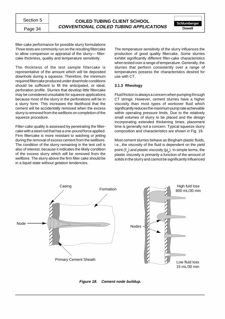
COILED TUBING CLIENT SCHOOLCONVENTIONAL COILED TUBING APPLICATIONS
Section 5
Page 34Schlumberger
Dowell
filter-cake performance for possible slurry formulationsThree tests are commonly run on the resulting filtercaketo allow comparison or appraisal of the slurry— filter-cake thickness, quality and temperature sensitivity.
The thickness of the test sample filtercake isrepresentative of the amount which will be depositeddownhole during a squeeze. Therefore, the minimumrequired filtercake produced under downhole conditionsshould be sufficient to fill the anticipated, or ideal,perforation profile. Slurries that develop little filtercakemay be considered unsuitable for squeeze applicationsbecause most of the slurry in the perforations will be ina slurry form. This increases the likelihood that thecement will be accidentally removed when the excessslurry is removed from the wellbore on completion of thesqueeze procedure.
Filter-cake quality is assessed by penetrating the filter-cake with a steel rod that has a one-pound force applied.Firm filtercake is more resistant to washing or jettingduring the removal of excess cement from the wellbore.The condition of the slurry remaining in the test cell isalso of interest, because it indicates the likely conditionof the excess slurry which will be removed from thewellbore. The slurry above the firm filter cake should bein a liquid state without gelation tendencies.
The temperature sensitivity of the slurry influences theproduction of good quality filtercake. Some slurriesexhibit significantly different filter-cake characteristicswhen tested over a range of temperature. Generally, theslurries that perform consistently over a range oftemperatures possess the characteristics desired foruse with CT.
3.1.3 Rheology
Fluid friction is always a concern when pumping throughCT strings. However, cement slurries have a higherviscosity than most types of workover fluid whichsignificantly reduces the maximum pump rate achievablewithin operating pressure limits. Due to the relativelysmall volumes of slurry to be placed and the designincorporating extended thickening times, placementtime is generally not a concern. Typical squeeze slurrycomposition and characteristics are shown in Fig. 19.
Most cement slurries behave as Bingham plastic fluids,i.e., the viscosity of the fluid is dependent on the yieldpoint (τy) and plastic viscosity (µp). In simple terms, theplastic viscosity is primarily a function of the amount ofsolids in the slurry and cannot be significantly influenced
Figure 18. Cement node buildup.
Node
���
�
�@AB
C
C���
�
�ÀÁÂ
Ã
���
�
�@AB
C
C���
�
�ÀÁÂ
Ã
���
�
�@AB
C
C���
�
�ÀÁÂ
Ã
���
�
�@AB
C
C���
�
�ÀÁÂ
Ã
���
�
�
���
�
�@AB
C
C���
�
�ÀÁÂ
Ã
���
�
�@AB
C
C���
�
�ÀÁÂ
Ã
���
�
�@AB
C
C���
�
�ÀÁÂ
Ã
���
�
�@AB
C
C���
�
�ÀÁÂ
Ã
���
�
�
FormationCasing
Primary Cement Sheath
�
�
�
�
�������
�������
�
�
�
@
@
@
@
AAAAAAA
BBBBBBB
C
C
C
�
�
�
�
�������
�������
�
�
�
À
À
À
À
ÁÁÁÁÁÁÁ
ÂÂÂÂÂÂÂ
Ã
Ã
Ã
�
�
�
�
�������
�������
�
�
�
@
@
@
@
AAAAAAA
BBBBBBB
C
C
C
�
�
�
�
�������
�������
�
�
�
À
À
À
À
ÁÁÁÁÁÁÁ
ÂÂÂÂÂÂÂ
Ã
Ã
Ã
�
�
�
�
�������
�������
�
�
�
@
@
@
@
AAAAAAA
BBBBBBB
C
C
C
�
�
�
�
�������
�������
�
�
�
À
À
À
À
ÁÁÁÁÁÁÁ
ÂÂÂÂÂÂÂ
Ã
Ã
Ã
�
�
�
�
�������
�������
�
�
�
@
@
@
@
AAAAAAA
BBBBBBB
C
C
C
�
�
�
�
�������
�������
�
�
�
À
À
À
À
ÁÁÁÁÁÁÁ
ÂÂÂÂÂÂÂ
Ã
Ã
Ã
�
�
�
�
�������
�������
�
�
�
�������
�
�
�
�
�
�
�
������
@@@@@@@
A
A
A
A
B
B
B
CCCCCC
�������
�
�
�
�
�
�
�
������
ÀÀÀÀÀÀÀ
Á
Á
Á
Á
Â
Â
Â
ÃÃÃÃÃÃ
�������
�
�
�
�
�
�
�
������
@@@@@@@
A
A
A
A
B
B
B
CCCCCC
�������
�
�
�
�
�
�
�
������
ÀÀÀÀÀÀÀ
Á
Á
Á
Á
Â
Â
Â
ÃÃÃÃÃÃ
�������
�
�
�
�
�
�
�
������
@@@@@@@
A
A
A
A
B
B
B
CCCCCC
�������
�
�
�
�
�
�
�
������
ÀÀÀÀÀÀÀ
Á
Á
Á
Á
Â
Â
Â
ÃÃÃÃÃÃ
�������
�
�
�
�
�
�
�
������
@@@@@@@
A
A
A
A
B
B
B
CCCCCC
�������
�
�
�
�
�
�
�
������
ÀÀÀÀÀÀÀ
Á
Á
Á
Á
Â
Â
Â
ÃÃÃÃÃÃ
�������
�
�
�
�
�
�
�
������
Nodes
Low fluid loss15 mL/30 min
High fuid loss800 mL/30 min

COILED TUBING CLIENT SCHOOLCONVENTIONAL COILED TUBING APPLICATIONS Page 35
Section 5Schlumberger
Dowell
Fig. 19.
TYPICAL SQUEEZE CEMENTING SLURRY COMPOSITION AND CHARACTERISTICS
Conventional Squeeze Slurry
Class G Cement+ 0.1 gal/sk D47 Antifoam+ 0.4% BWOC D156 Fluid-Loss Additive+ 0.5% BWOC D65 Dispersant+ 0.2% BWOC D800 Retarder+ 0.1 gal/sk D135 Surfactant (shear bond/fluid-loss enhancer)+ 0.5% BWOC D20 Slurry Stabilizer+ 5.05 gal/sk Fresh Water
Density 15.6 lb/galYield 1.19 ft3/skFilter Cake 0.8 in. — firmFluid Loss 67 mL/30 min (170°F BHCT)Thickening Time 7 hr 20 min to reach 70 Bc (180°F BHST)Bingham Yield 9.5 lb/100 ft2 (95°F), 9.2 lb/100 ft2 (170°F)Plastic Viscosity 39.2 cp (95°F), 37.3 cp (170°F)
No free water/sedimentation. D20 is prehydrated in water, all additives are mixed inwater, and cement is added in 15 sec at 12,000 rpm for 180 sec.
Latex Cement Squeeze Slurry
Class G Cement+ 0.1 gal/sk D47 Antifoam+ 1.3 gal/sk D134 Latex Fluid-Loss Additive+ 0.4% BWOC D65 Dispersant+ 0.5% BWOC D800 Retarder+ 0.10 gal/sk D135 Surfactant (shear bond/fluid-loss enhancer)+ 1.0% BWOC D20 Slurry Stabilizer+ 3.82 gal/sk Fresh Water
Density 15.6 lb/galYield 1.21 ft3/skFilter Cake 0.7 in. — firmFluid Loss 58 mL/30 min (170°F BHCT)Thickening Time 7 hr 29 min to reach 70 Bc (180°F BHST)Bingham Yield 17 lb/100 ft2 (95°F), 12 lb/100 ft2 (170°F)Plastic Viscosity 34 cp (95°F), 34 cp (170°F)
No free water/sedimentation. D20 is prehydrated in water, all additives are mixed inwater, and cement is added in 15 sec at 12,000 rpm for 180 sec.

COILED TUBING CLIENT SCHOOLCONVENTIONAL COILED TUBING APPLICATIONS
Section 5
Page 36Schlumberger
Dowell
by additives. The yield point is a measure of thedistribution of the particles in the slurry. The yield point,and therefore the viscosity, of a slurry can be altered byadding dispersants. However, care must be exercisedin the use of dispersants because it is possible tooverdisperse a slurry, in which case settling of thecement solids will occur. A prerequisite for CT squeezeslurries is no settled solids and no free water.
The apparent viscosity (µa) is commonly used inspecifying the characteristics of a cement slurry since itis relatively easily measured using a FANN 35Viscometer.
Optimum rheological values for CT squeeze cementslurries are
Minimum possible τy (5 to 10 lbf/100 ft2)
Minimum possible µp (less than 50cP)
Since cementing operations may require the CT toremain inside a column of cement for an extendedperiod, no gel- strength buildup should be evident withintwo hours at BHST.
Rheology and stability tests are commonly performed atsurface mixing temperatures and at BHST. In generalstable slurries provide good rheology characteristicswhich are are easily reproducible.
3.2 Design
3.2 .1 Slurry Volume
The appropriate volume of slurry prepared for a CTcement squeeze is dependent on several factors. Inmost cases, previous squeeze experience in the sameor similar reservoirs will provide the best guidelines.Although it is desirable to achieve a successful squeezein one operation, some hazards exist if the slurry volumeis excessive. Conversely, the minimum practical slurryvolume is that which will ensure correct placement of thenecessary volume of uncontaminated cement.
The following factors influence the slurry volume:
• Length of perforated interval and capacity of liner/casing.
• Void areas behind the perforations resulting from theerosion of friable and unconsolidated formations or
from stimulation treatments.• The force applied to the tubing, i.e., in deep applications,
the additional tension resulting from the cement insidethe CT may exceed operating limits.
• The configuration of surface mixing and pumpingequipment i.e., reducing the volume of surface lines(especially large-diameter lines) reduces the likeli-hood of slurry contamination.
• Use of cement plugs, pigs or darts to ensure separationof slurry in the CT string reduces the excess slurryvolume necessary to account for contamination. Inaddition, the plugs can provide a positive indication ofslurry location.
When using CT to place a fluid column in a wellbore, theultimate position of the fluid column is primarily dictatedby the location of the CT nozzle and by the volume offluid pumped. Consequently, fluid volumes must becarefully designed, measured and confirmed whenperforming operations requiring critical depth control.
3.2.2 Slurry Placement
The success of any cement squeeze is dependent onthe accurate placement of an uncontaminated slurrywhich has the desired characteristics. The followingfactors are of importance during slurry placement:
• Depth control
• Contamination protection
• Cement column stability
• Isolation of adjacent zones
• Tubing movement
3.2.3 Depth Correlation
Depth-sensitive applications, such as cement squeezing,generally require the CT nozzle to be positioned andcontrolled using a higher degree of accuracy than canbe achieved using surface measuring equipment. Theeffects of stretch, buckling and residual bend can bevariable and considerable. For this reason a downholereference point is generally required to achieve thenecessary accuracy of placement.
There are three methods of acquiring a depth reference:log correlation, tagging bottom or tagging completion
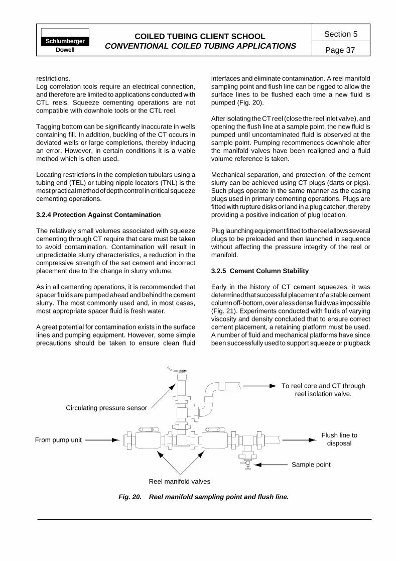
COILED TUBING CLIENT SCHOOLCONVENTIONAL COILED TUBING APPLICATIONS Page 37
Section 5Schlumberger
Dowell
restrictions.Log correlation tools require an electrical connection,and therefore are limited to applications conducted withCTL reels. Squeeze cementing operations are notcompatible with downhole tools or the CTL reel.
Tagging bottom can be significantly inaccurate in wellscontaining fill. In addition, buckling of the CT occurs indeviated wells or large completions, thereby inducingan error. However, in certain conditions it is a viablemethod which is often used.
Locating restrictions in the completion tubulars using atubing end (TEL) or tubing nipple locators (TNL) is themost practical method of depth control in critical squeezecementing operations.
3.2.4 Protection Against Contamination
The relatively small volumes associated with squeezecementing through CT require that care must be takento avoid contamination. Contamination will result inunpredictable slurry characteristics, a reduction in thecompressive strength of the set cement and incorrectplacement due to the change in slurry volume.
As in all cementing operations, it is recommended thatspacer fluids are pumped ahead and behind the cementslurry. The most commonly used and, in most cases,most appropriate spacer fluid is fresh water.
A great potential for contamination exists in the surfacelines and pumping equipment. However, some simpleprecautions should be taken to ensure clean fluid
interfaces and eliminate contamination. A reel manifoldsampling point and flush line can be rigged to allow thesurface lines to be flushed each time a new fluid ispumped (Fig. 20).
After isolating the CT reel (close the reel inlet valve), andopening the flush line at a sample point, the new fluid ispumped until uncontaminated fluid is observed at thesample point. Pumping recommences downhole afterthe manifold valves have been realigned and a fluidvolume reference is taken.
Mechanical separation, and protection, of the cementslurry can be achieved using CT plugs (darts or pigs).Such plugs operate in the same manner as the casingplugs used in primary cementing operations. Plugs arefitted with rupture disks or land in a plug catcher, therebyproviding a positive indication of plug location.
Plug launching equipment fitted to the reel allows severalplugs to be preloaded and then launched in sequencewithout affecting the pressure integrity of the reel ormanifold.
3.2.5 Cement Column Stability
Early in the history of CT cement squeezes, it wasdetermined that successful placement of a stable cementcolumn off-bottom, over a less dense fluid was impossible(Fig. 21). Experiments conducted with fluids of varyingviscosity and density concluded that to ensure correctcement placement, a retaining platform must be used.A number of fluid and mechanical platforms have sincebeen successfully used to support squeeze or plugback
To reel core and CT throughreel isolation valve.
Flush line todisposal
Sample point
From pump unit
Circulating pressure sensor
Reel manifold valves
Fig. 20. Reel manifold sampling point and flush line.

COILED TUBING CLIENT SCHOOLCONVENTIONAL COILED TUBING APPLICATIONS
Section 5
Page 38Schlumberger
Dowell
cement slurries:• excess cement slurry
• weighted gel
• sand
• PROTECTOZONE* Fluid
• calcium carbonate
• through-tubing bridge plug.
The nature and size of an appropriate platform shouldbe determined for each case. Under some conditions itmay be appropriate to place the cement column from thebottom of the rat hole.
Isolation of adjacent perforations below the zone to besqueezed can be achieved by similar methods to thoseshown above for providing a platform. However, it iscommon for all perforations around the squeeze zone tobe cemented. Selective reperforation of the interval hasachieved better results with the benefit of less complex
job design.Placement techniques for fluids or plugs conveyed byCT differ from conventional drillpipe or tubing conveyedmethods.Capillary forces associated with the relativelysmall ID tube restrict the ability of viscous fluids to fallfrom the tubing while pulling up. Attempting to pull upthrough a placed plug will result in cement stringersbeing pulled uphole.
The technique commonly used to place plugs takesadvantage of a basic feature of coiled tubing operations,i.e., the ability to pump fluids while moving the tubing.Once the cement/spacer interface starts rising in theannulus, the CT nozzle is withdrawn at a rate whichmaintains the nozzle within the rising slurry column. TheCT nozzle should be kept at least 50 to 100 ft below thetop interface while the column is being placed. As thelast of the cement is pumped from the CT, the nozzleshould be withdrawn above the theoretical top of thecement (TOC).
This technique will result in a clean cement interface.Further tubing movement, circulation or reversecirculation will be determined by operationalrequirements.
Cement slurry fallsthrough less dense fluidsresulting in contaminationand improper placement
of the cement columnover the treatment zone.
Cement platform consistingof a high density fluid, sandor similar particulates, or athrough tubing bridge plug.
Stable cementcolumn placed over
the platform.
�����
����
�����
@@@@@
@@@@
@@@@@
�����
����
�����
ÀÀÀÀÀ
ÀÀÀÀ
ÀÀÀÀÀ
�����
����
�����
@@@@@
@@@@
@@@@@
�����
����
�����
ÀÀÀÀÀ
ÀÀÀÀ
ÀÀÀÀÀ
�����
����
�����
@@@@@
@@@@
@@@@@
�����
����
�����
ÀÀÀÀÀ
ÀÀÀÀ
ÀÀÀÀÀ
�����
����
�����
@@@@@
@@@@
@@@@@
�����
����
�����
ÀÀÀÀÀ
ÀÀÀÀ
ÀÀÀÀÀ
�����
����
�����
Fig. 21. Cement placement with and without a retaining platform.
* Mark of Schlumberger

COILED TUBING CLIENT SCHOOLCONVENTIONAL COILED TUBING APPLICATIONS Page 39
Section 5Schlumberger
Dowell
3.2.6 Tool Selection
Tool strings used in conjunction with cement squeezesshould generally be kept to a minimum. However, thereare a number of functions which may be requireddepending on the application.
• Connector
Required on all jobs. The simple connectors are lesssensitive to accidental cement invasion than the Dowellgrapple.
When using cement plugs, pigs or balls, connectorsthat deform the internal surface of the CT (e.g., dimple/setscrew and roll-on connectors) should be checkedfor adequate clearance.
• Check Valves
Cannot be used when procedures call for reversecirculation of excess cement from the wellbore. Whenfitted, only full-bore flapper check valves should beused.
• Depth Correlation
Tubing end or nipple locators are commonly used toconfirm depth; however, many treatments are per-formed using TD as a reference point.
• Plug Catcher
For use with plugs ahead or behind the cement slurry.Essentially to catch and retrieve the plugs, someversions provide some indication that the plug hasseated by causing a pressure increase visible at thesurface.
• Nozzles
A variety of jetting nozzles have been developed toimprove the slurry placement. In addition, some morecomplex designs are intended to ensure satisfactoryremoval of excess cement by reverse circulation.
While it is advantageous to perform all aspects of theoperation without changing the nozzle or BHA, somefunctions ideally require different nozzle/jet configura-tions. For example, to clean and condition the wellboreand to place the cement slurry, a nozzle with multipleside-facing jets is preferred. However, if excess slurryis to be removed by reverse circulation, a single large-port nozzle (to avoid plugging) is preferable. Combina-tion nozzles (Fig.22) are designed to provide improvedreverse circulating and jetting capabilities.
��@@��ÀÀ��@@��ÀÀ��@@��ÀÀ��@@��ÀÀ�����
����
����
����
����
����
��
@@@
@@@@
@@@@
@@@@
@@@@
@@@@
@@
���
����
����
����
����
����
��
ÀÀÀ
ÀÀÀÀ
ÀÀÀÀ
ÀÀÀÀ
ÀÀÀÀ
ÀÀÀÀ
ÀÀ
���
����
����
����
����
����
��
@@@
@@@@
@@@@
@@@@
@@@@
@@@@
@@
���
����
����
����
����
����
��
ÀÀÀ
ÀÀÀÀ
ÀÀÀÀ
ÀÀÀÀ
ÀÀÀÀ
ÀÀÀÀ
ÀÀ
���
����
����
����
����
����
��
@@@
@@@@
@@@@
@@@@
@@@@
@@@@
@@
���
����
����
����
����
����
��
ÀÀÀ
ÀÀÀÀ
ÀÀÀÀ
ÀÀÀÀ
ÀÀÀÀ
ÀÀÀÀ
ÀÀ
���
����
����
����
����
����
��
@@@
@@@@
@@@@
@@@@
@@@@
@@@@
@@
���
����
����
����
����
����
��
ÀÀÀ
ÀÀÀÀ
ÀÀÀÀ
ÀÀÀÀ
ÀÀÀÀ
ÀÀÀÀ
ÀÀ
���
����
����
����
����
����
��
���@@@���ÀÀÀ���@@@���ÀÀÀ���@@@���ÀÀÀ���@@@���ÀÀÀ���
����@@@@����ÀÀÀÀ����@@@@����ÀÀÀÀ����@@@@����ÀÀÀÀ����@@@@����ÀÀÀÀ����
Multiple small-diameterradial ports provide
improved jetting pattern.
improved jetting/circulation nozzlereverse circulating nozzle
�@�À�@�À�@�À�@�À�
��@@��ÀÀ��@@��ÀÀ��@@��ÀÀ��@@��ÀÀ��
����
����
����
����
����
��
@@@@
@@@@
@@@@
@@@@
@@@@
@@
����
����
����
����
����
��
ÀÀÀÀ
ÀÀÀÀ
ÀÀÀÀ
ÀÀÀÀ
ÀÀÀÀ
ÀÀ
����
����
����
����
����
��
@@@@
@@@@
@@@@
@@@@
@@@@
@@
����
����
����
����
����
��
ÀÀÀÀ
ÀÀÀÀ
ÀÀÀÀ
ÀÀÀÀ
ÀÀÀÀ
ÀÀ
����
����
����
����
����
��
@@@@
@@@@
@@@@
@@@@
@@@@
@@
����
����
����
����
����
��
ÀÀÀÀ
ÀÀÀÀ
ÀÀÀÀ
ÀÀÀÀ
ÀÀÀÀ
ÀÀ
����
����
����
����
����
��
@@@@
@@@@
@@@@
@@@@
@@@@
@@
����
����
����
����
����
��
ÀÀÀÀ
ÀÀÀÀ
ÀÀÀÀ
ÀÀÀÀ
ÀÀÀÀ
ÀÀ
����
����
����
����
����
��
���@@@���ÀÀÀ���@@@���ÀÀÀ���@@@���ÀÀÀ���@@@���ÀÀÀ���
����@@@@����ÀÀÀÀ����@@@@����ÀÀÀÀ����@@@@����ÀÀÀÀ����@@@@����ÀÀÀÀ����
Multiple small-diameterradial ports provide
improved cement place-ment and jetting pattern.
Pins to retain ball withinthe nozzle.
Large-diameter portopen during reverse
circulation and closedwhen jetting or placing
cement.
Large diameter portsopen during cement
placement and closed bythe drop ball when jetting
and circulating out theexcess cement.
Fig. 22. Cementing nozzle features.
COILED TUBING CLIENT SCHOOLCONVENTIONAL COILED TUBING APPLICATIONS
Section 5
Page 40Schlumberger
Dowell
3.3 Squeeze Cementing Operations
In many cementing operations, the cement settingprocess provokes a sense of urgency which can affectthe normal decision-making ability of personnel. Therisk of premature setting and the correspondingoperational difficulties can impose a sense of urgencythat results in misguided actions which are neithermethodical or necessary. Principally for this reason, it isessential that clear and precise procedures be preparedfor the entire cementing operation. This should includedetails of normal, contingency and emergency operatingprocedures.
3.3.1 Execution Precautions
Execution precautions to be observed during squeezecement treatments relate to the safety in handling ofcement and chemicals, ensuring the correct placementof a slurry with the desired characteristics and ensuringthat cement deposits do not remain in the CT or pressurecontrol equipment on completion of the operation.
Personnel
All personnel involved in the design or execution ofsqueeze cementing or CT services must be familiar withrequirements detailed in the relevant Safety and LossPrevention (S&LP) Standards.
Well Security
The control of well pressure and fluids must meet therequirements of the relevant S&LP Standards. In addition,the requirements of the operating company andapplicable regulatory authorities must be known.
Equipment
All Dowell treating and monitoring equipment must bespotted and operated in accordance with therequirements of the relevant S&LP Standards. In addition,equipment certified for use in hazardous areas must beoperated and maintained in accordance with theoperating zone requirements.
3.3.2 Equipment Requirements
A schematic diagram of typical equipment layout isshown in Fig. 23.
Coiled Tubing Equipment
Some operating companies require that the work-stringvolume be checked by inserting and displacing a plug orfoam pig. Such checks can be combined with thedisplacement of pickling treatments where required.
To minimize contamination, a flushing/sampling manifoldshould be rigged up on the CT reel.
When pumping high-density fluids through the CT workstring, there may be significant changes in the stringtension forces.
All manifolds and valves should be flushed to ensurethat all traces of cement are removed.
Pressure Control Equipment
All manifolds and valves should be flushed to ensurethat all traces of cement are removed.
Pumping Equipment
All fluid mixing, pumping and storage equipment mustbe clean and configured to avoid contamination ordilution of the cement slurry.
Pressure and rate limits (governed by the CT equipmentor reservoir conditions) for every stage of the operationmust be defined and noted on the pumping schedule.
All manifolds and valves should be flushed to ensurethat all traces of cement are removed.
Monitoring and Recording
Accurate monitoring and recording of the job parametersis essential to allow complete control of the job andpreparation of postjob reporting and analyses. Theschematic diagram in Fig.24 identifies typical jobparameters and their point of measurement/recording.
Downhole Equipment
A complete fishing diagram must be prepared to includeall downhole equipment. In addition, the operation of alltools must be fully understood.
3.3.3 Treatment Execution
The steps required to successfully complete a cementsqueeze will depend on the particular conditions

COILED TUBING CLIENT SCHOOLCONVENTIONAL COILED TUBING APPLICATIONS Page 41
Section 5Schlumberger
Dowell
Riser pump-in tee
Flowline
Coiled tubingBOP
Displacementfluid
Displacementfluid
Fresh water/spacer
Cement
Gauge tank
To degasser
Triplexpump
Sample point
Bleedoff
Samplepoint
Squeeze manifold
Chokemanifold
Flushline
Fig. 23. Typical squeeze cementing equipment configuration.
encountered in each case. In the following section, thekey points in each phase of the cementing operation areoutlined. When preparing and documenting a treatmentprocedure, it is recommended that the key points arereviewed and the applicable points incorporated into theprocedure as required.
Cementing operations are frequently conducted inmultiple well campaigns within a field or area.Consequently, procedures are often tuned to meet localconditions by application of the DESIGN, EXECUTEand EVALUATE* cycle. Whenever possible, previouscase histories for similar applications should bereferenced.
* Mark of Schlumberger

COILED TUBING CLIENT SCHOOLCONVENTIONAL COILED TUBING APPLICATIONS
Section 5
Page 42Schlumberger
Dowell
Execution of squeeze cementing operations isaccomplished in four basic steps:
• wellbore preparation
• slurry mixing and pumping
• squeeze
• removal of excess cement.
See Fig 26 through Fig 33.
Welbore Preparation
In preparing the wellbore and completion for squeezecementing operations, several operations are commonlycompleted. Slick-line conveyed tools and methods are
generally used where possible; however, in deviated orunusual conditions, CT is capable of completing allpreparatory work.
Wellbore preparation operations will generally includethe following:
• Slick-line work, e.g., fitting dummy gas-lift mandrels.
• Pressure test the production tubing annulus.
• Establish hangup depth or TD using slick line.
• Confirm and correlate depths with CT and flag thetubing.
Coiled tubing
• Monitor and record pressure,rate/volume, string weight,depth and tubing OD and tub-ing cycles.
Pump unit
• Monitor and record pressure,density and pump rate/volume.
Slurry batch mixer
• Monitor density and volume.
Other tankage
• Monitor density and volume.
Fig. 24. Squeeze cementing parameters to be monitored and recorded.
Annulus
• Monitor volume and densityof all fluids returned andpumped through annulus.
• Record pressure.

COILED TUBING CLIENT SCHOOLCONVENTIONAL COILED TUBING APPLICATIONS Page 43
Section 5Schlumberger
Dowell
• Remove fill from the rathole below perforated interval.
• Perform pretreatment perforation wash or acidizing.
• Place a stable platform for the cement slurry.
• Ensure that the wellbore is fully loaded with filteredwater (or equivalent).
Slurry Mixing and Pumping
Before mixing and preparing the slurry, the wellboreshould be fluid filled and a stable and adequate cementingplatform should be in place. In addition, placementdepths should be confirmed and the CT flagged atcritical points, e.g., anticipated top and bottom of theplaced cement column.
Key points in the slurry mixing and pumping processinclude the following:
• Batch mix and shear the slurry ensuring that additiveproportions are accurately measured. Contingencyplans should be made for dumping or disposal of slurrywhich fails to meet the required specifications.
• Conduct job-site quality control tests (filtercake, fluidloss, rheology).
• Prepare contaminant and spacer fluids as required.Equipment rig-up should be configured to avoid acci-dental contamination on the surface.
• Confirm CT depth and coordinate tubing movementwith pumped volumes. The CT nozzle movement andlocation must be closely aligned to the fluid type andvolume exiting the nozzle. Pump operators and CTUoperators must have a mutual understanding of theoperation to be completed. It is also essential that theyhave a clear line of communication.
• Lay in cement slurry following the prepared pumpingschedule (Fig. 33) . While spotting the cement column,it is essential that the wellbore remain fully loaded withfluid to prevent gas migration in the CT productiontubing annulus.
The following guidelines should be considered to reducethe risks of operational failure when using thixotropiccements.
• Do not stop pumping while thixotropic cement is insidethe work string.
• Place the CT nozzle above the thief zone and pumpdown the production tubing/CT annulus while squeez-ing the cement.
• Overdisplace thixotropic cement slurries out of thewellbore. Once the slurry achieves a high initial gelstrength, it may be impossible to clean the wellbore bycirculation (or reverse circulation).
Squeeze
The effect of placing and squeezing cement slurryacross the treatment zone is often unknown. Squeezepressure may build quickly as the slurry contacts theformation face, or in formations with fractures or voidspaces behind the liner or casing, squeeze pressuremay not be achieved. Consequently, preparedprocedures must detail actions to be taken for a numberof events which may or may not occur.
The downhole generation of filter cake is aided byperforming hesitation type squeezes (e.g., 10 min at1000 psi, 15 min at 1500 psi, 20 min at 2000 psi....). Asthe fracture pressure is exceeded during this process,the filter cake prevents the formation from fracturing. Afirm filter cake is formed which contributes greatly to thesuccess of the squeeze operation.
• To reduce the risk of sticking, the CT nozzle should beconstantly or at least frequently moved during theoperation.
• When displacing the spacer and slurry, the CT shouldbe at the lower flagged depth when the spacer exitsthe nozzle. When 50 ft of cement has been placedabove the nozzle, the CT should be slowly withdrawnfrom the wellbore. To minimize the risk of dilution/contamination, the nozzle should be kept at least 50 ftbelow the top cement interface. With a flowmeterplaced in the annular return line, the volumes pumpedand returned can be compared to determine thesqueezed slurry volume.
• The annular/choke manifold pressure must be closelymonitored and controlled during the cement placementand squeeze. A clear line of communication must existbetween the choke manifold operator, pump unit op-erator and CTU operator.
• If squeeze pressure builds before all of the cement hasleft the CT, the cement should be laid in while balanc-ing the returns with fluid pumped, i.e., fluid return rateshould equal the fluid pump rate through the CT. The

COILED TUBING CLIENT SCHOOLCONVENTIONAL COILED TUBING APPLICATIONS
Section 5
Page 44Schlumberger
Dowell
CT nozzle should be at the top cement interface as thelast of the slurry exits the nozzle.
• The nozzle should be located 50ft above the TOCbefore attempting to squeeze the cement. For safety,assume TOC as worst case, with no cement beingplaced behind the perforations.
• If squeeze pressure does not build when the interval iscovered with cement, use a hesitation technique toattempt pressure buildup in stages. The hesitationperiods are dependent on how much slurry the well"takes" and the volume of slurry available for thesqueeze.
• If the squeeze "breaks back" during a pumping stage,the hesitation sequence should be resumed. This isoften an indication that perforations previously pluggedby debris have broken down and are now acceptingfluid.
• Maintain slow circulation through the CT and controlBHP by choking the returns. Closely monitor the returnvolume and rate.
• When final squeeze pressure is achieved, continuecirculating and holding pressure on the annular chokefor one hour.
• On completion of the squeeze sequence, stop circula-tion, close choke and monitor the wellhead pressureWHP.
• Slowly bleed off the pressure to approximately 500 to1000 psi above the BHP and prepare for cleanoutoperations.
Removal of Excess Cement
An important feature of CT workovers is the ability tocomplete operations and restore the well to productionin a relatively short time. In the case of squeeze cementingoperations, efficient removal of excess cement from thewellbore is critical to the timely completion of the job.Efficient removal of the slurry without jeopardizing theintegrity of the cement nodes can be achieved usingseveral methods, which may be summarized as follows.
• reverse circulation of live cement
• circulation of contaminated cement
• reverse circulation of contaminated cement.
The Dowell operational requirements for reversecirculation through CT workstrings, as detailed in S&LPStandard, No. 22, must be understood and fullyimplemented in any operation in which reverse circulationis to be performed.
During removal of the excess cement it is generallydesirable to maintain a positive squeeze pressure overthe treated zone. In effect, this is automatically appliedin the case of reverse circulation techniques by thefriction pressure created when lifting fluid through thework string. Cleanouts performed by conventionalcirculation should have the back pressure controlled bya surface choke.
Key points relating to the methods of removing excesscement are detailed below.
Reverse Circulating of Live Cement
Reverse circulation of live cement slurry (uncontaminatedslurry) can be safely performed if the following conditionsare met:
• The designed slurry thickening time (including safetyfactor) should allow for completion of the reversingphase of the operation.
• The CT penetration rate is controlled to effectivelydilute the slurry as it is removed (maximum density ofreversed fluid is 10 lb/gal).
• Reversing is continued until clean returns are observedat the surface.
Typical procedures for reversing live cement include thefollowing steps:
• With the CT nozzle positioned above the spacer fluid,establish circulation down the CT production tubingannulus. Maintain a stable pump rate which does notexceed the maximum allowable differential on the CTat the wellhead (1500 psi).
• Penetrate the spacer and cement column with thenozzle at a rate which ensures 50% dilution of theexcess slurry. This serves to reduce the hydrostaticpressure acting inside the work string and aids removal.
• The CT should be run to the the lower flag mark withcirculation maintained until clean returns are observedat the surface.

COILED TUBING CLIENT SCHOOLCONVENTIONAL COILED TUBING APPLICATIONS Page 45
Section 5Schlumberger
Dowell
Pumping Schedule
Workstring capacity 16.23 bbl
Bullhead filtered seawater (200 bbl)3 bbl/min <1200 psi 8.7 lb/gal 200 bbl
Filtered seawater while RIH with CT0.5 bbl/min <1000 psi 8.7 lb/gal 90 bbl
Gel/sand cement platform (20 bbl)2.0 bbl/min <4000 psi 14.0 lb/gal 16 bbl
4 bbl
Fresh water spacer (15 bbl)2.0 bbl/min <4000 psi 8.7 lb/gal 15 bbl
Cement slurry (20 bbl)2.0 bbl/min <4000 psi 16.0 lb/gal 17 bbl
3 bblFresh water spacer (5bbl)Displacement Fluid (25 bbl)
2.0 bbl/min <4000 psi 8.6 lb/gal 4 bbl
If squeeze pressure builds, lay in remainingcement while gauging returns one for one.
16 bbl
Continue displacement to obtain squeeze.10 bbl
Contaminant (50 bbl)Max. rate <4000 psi 8.5 lb/gal...................
Tubing Movement
Treatment zone 13,500 to 13420 ft (TD 13,580)
Swab valve closed
RIH to tag TD75 ft/min 13,580 ft
At TD 13,580 ft With 16 bbl pumped, start POOH
50 ft/min stop at 13,500 13,500 ft
Allow sand to settle (30 min)tag at 13,520 ft 13,520 ft
Nozzle 10 ft above tagged sand 13,510 ft
With 17 bbl of slurry pumped, start POOH50 ft/min
With 16 bbl displaced,nozzle should be at TOC 13,000 ft
RIH through excess slurry25 ft/min..........................
Annulus Choke
Closed
Closed
Open
Open
Open
Open
After 4 bbl of dis-placement, chokeand gauge returns.1200 psi max.
Build to final squeezepressure of 2000 psi.
EXAMPLE SQUEEZE CEMENTING PUMPING SCHEDULE
• Commence reverse circulation again at previous pumpand penetration rates until clean returns are observed.
• If required, displace the annulus to nitrogen to achievethe necessary underbalance to test and evaluate thesqueeze. Maintain sufficient WHP to apply positivesqueeze pressure until the cement has achievedsufficient compressive strength to allow testing(generally after 24 hr).
Fig. 25.
• After clean returns are observed, change to circulationthrough the CT with returns choked to maintain positivesqueeze pressure. Make a jetting pass through thetreated zone. The jetting fluid pump rate should gen-erally be reduced when passing the treatment zone toavoid damaging the cement nodes. The interval abovethe treated zone can be jetted at an increased rate.

COILED TUBING CLIENT SCHOOLCONVENTIONAL COILED TUBING APPLICATIONS
Section 5
Page 46Schlumberger
Dowell
Fig. 26.. Wellbore preparation.
Choke open.
Wellbore clean andpacked.
Preparation
Fig. 28. Placing thixotropic slurries.
Slurry pumped atmaximum rate/
pressure allowed.Choke open.
Spacer/freshwater
Fig. 27. Laying in cement slurry.
Slurry pumped atmaximum rate/
pressure allowed.
Choke closed, if thewellbore is not fluid
packed, pump slowlydown annulus toprevent U-tubing.
Wellborepack fluid
Nozzle pulled up50 ft below cement
interface.
Nozzle placedabove thief zone.
Placing the Slurry
Filteredseawater, or
similar, at highrate.
Cementslurry
Wellborepackfluid.
Cementslurry
Wellborepack fluid
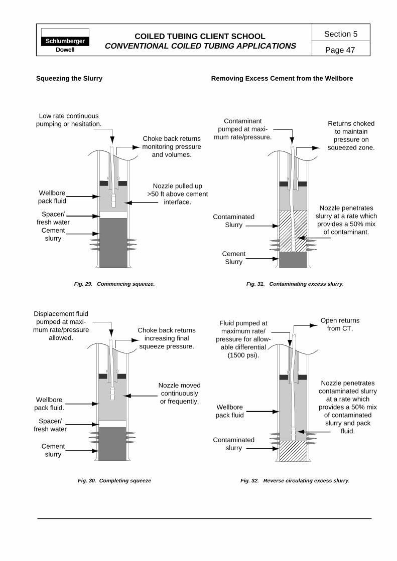
COILED TUBING CLIENT SCHOOLCONVENTIONAL COILED TUBING APPLICATIONS Page 47
Section 5Schlumberger
Dowell
Squeezing the Slurry Removing Excess Cement from the Wellbore
Fig. 29. Commencing squeeze. Fig. 31. Contaminating excess slurry.
Fig. 30. Completing squeeze Fig. 32. Reverse circulating excess slurry.
Cementslurry
Spacer/fresh water
Wellborepack fluid
Nozzle pulled up>50 ft above cement
interface.
CementSlurry ��
��
����
���
@@@@
@@@@
@@@
����
����
���
ÀÀÀÀ
ÀÀÀÀ
ÀÀÀ
����
����
���
@@@@
@@@@
@@@
����
����
���
ÀÀÀÀ
ÀÀÀÀ
ÀÀÀ
����
����
���
@@@@
@@@@
@@@
����
����
���
ÀÀÀÀ
ÀÀÀÀ
ÀÀÀ
����
����
���
@@@@
@@@@
@@@
����
����
���
ÀÀÀÀ
ÀÀÀÀ
ÀÀÀ
����
����
���
��
����
���
@@
@@@@
@@@
��
����
���
ÀÀ
ÀÀÀÀ
ÀÀÀ
��
����
���
@@
@@@@
@@@
��
����
���
ÀÀ
ÀÀÀÀ
ÀÀÀ
��
����
���
@@
@@@@
@@@
��
����
���
ÀÀ
ÀÀÀÀ
ÀÀÀ
��
����
���
@@
@@@@
@@@
��
����
���
ÀÀ
ÀÀÀÀ
ÀÀÀ
��
����
���Cement
slurry
Spacer/fresh water
Wellborepack fluid.
Fluid pumped atmaximum rate/
pressure for allow-able differential
(1500 psi).
Contaminantpumped at maxi-
mum rate/pressure.
Wellborepack fluid
Choke back returnsmonitoring pressure
and volumes.
Nozzle movedcontinuouslyor frequently.
Choke back returnsincreasing final
squeeze pressure.
Nozzle penetratesslurry at a rate whichprovides a 50% mix
of contaminant.
Returns chokedto maintainpressure on
squeezed zone.
Nozzle penetratescontaminated slurry
at a rate whichprovides a 50% mix
of contaminatedslurry and pack
fluid.Contaminated
slurry
ContaminatedSlurry
Open returnsfrom CT.
Low rate continuouspumping or hesitation.
Displacement fluidpumped at maxi-
mum rate/pressureallowed.

COILED TUBING CLIENT SCHOOLCONVENTIONAL COILED TUBING APPLICATIONS
Section 5
Page 48Schlumberger
Dowell
Fig. 34. Wellbore circulated clean.
Fig. 33. Reverse circulating live slurry.
Wellborepack fluid
Cementslurry
Nozzle penetratesslurry at a rate which
provides a 50%mix.
Fluid pumped atmaximum rate/
pressure for allow-able differential
(1500 psi).
Open returnsfrom CT.
Wellborepack fluid
Fluid pumped atmaximum rate/
pressure.Returns choked
to maintainpressure on
squeezed zone.
Nozzle reciprocatedthrough treatment
zone to TD.
Differentialpressure main-tained against
squeezed zone.
Removing Excess Cement from the Wellbore Reverse Circulating Contaminated Cement
Contamination of the excess cement is often necessaryto extend the slurry thickening time, thereby allowingcleanout operations to be completed safely. In addition,contaminating the excess slurry can allow cleanoutoperations to be delayed until the cement nodes haveincreased the compressive strength. In this way thelikelihood of damaging the treated zone is reduced.However, unless the contaminant is correctly andthoroughly applied, there is some risk of partiallyobstructing the wellbore with set cement. Typical borax/bentonite and biopolymer contaminant formulations areshown in Fig. 35.
Typical procedures for contaminating excess cementinclude the following steps:
• With the CT nozzle positioned above the worst casecement top, establish circulation of the contaminantthrough the CT while maintaining the desired chokepressure at the surface.
• Penetrate the slurry at a rate which ensures a 50%mixture of contaminant and cement slurry.
• Reduce the pump rate and penetration rate across thetreated zone to minimize the risk of damaging thecement nodes.
• Continue the contamination run to the lowest slurrylevel.
• POOH while continuing to pump the contaminant.Maintain a pump rate and withdrawal rate sufficient toensure a final dilution/contamination ratio of 1.5:1 (1.5parts contaminant to 1 part slurry).
• When the nozzle is at the top of the contaminatedcolumn begin reversing as detailed in Reversing Cir-culating Live Cement.
Circulation of Contaminated Cement
In the event that the operating conditions cannot safelysupport reverse circulation of the excess slurry,conventional circulation may be used. For example,operations performed through 1-1/4-in. work stringscannot employ reverse circulation techniques due to theexcessive friction pressure encountered. Typicalprocedures for the circulation/contamination of excesscement slurry include the following steps:
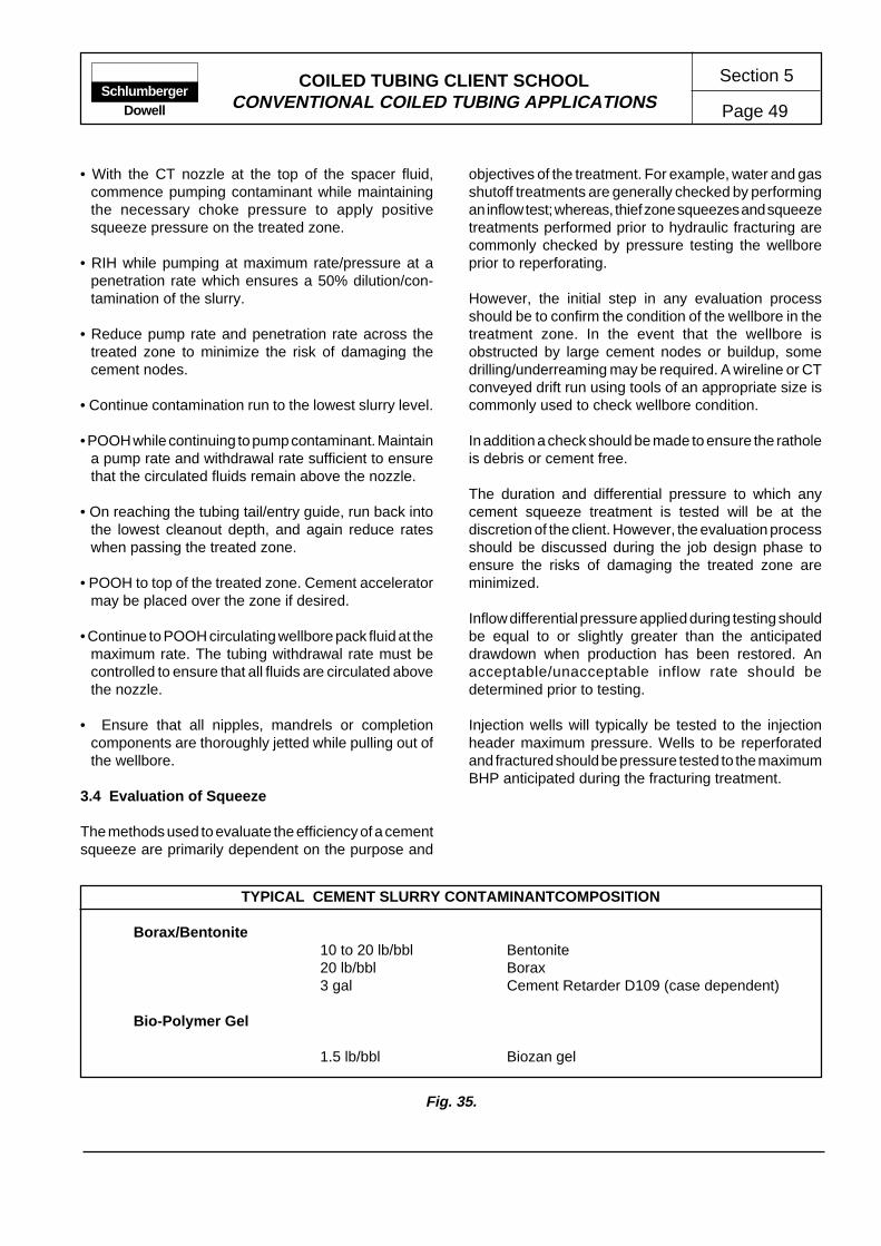
COILED TUBING CLIENT SCHOOLCONVENTIONAL COILED TUBING APPLICATIONS Page 49
Section 5Schlumberger
Dowell
• With the CT nozzle at the top of the spacer fluid,commence pumping contaminant while maintainingthe necessary choke pressure to apply positivesqueeze pressure on the treated zone.
• RIH while pumping at maximum rate/pressure at apenetration rate which ensures a 50% dilution/con-tamination of the slurry.
• Reduce pump rate and penetration rate across thetreated zone to minimize the risk of damaging thecement nodes.
• Continue contamination run to the lowest slurry level.
• POOH while continuing to pump contaminant. Maintaina pump rate and withdrawal rate sufficient to ensurethat the circulated fluids remain above the nozzle.
• On reaching the tubing tail/entry guide, run back intothe lowest cleanout depth, and again reduce rateswhen passing the treated zone.
• POOH to top of the treated zone. Cement acceleratormay be placed over the zone if desired.
• Continue to POOH circulating wellbore pack fluid at themaximum rate. The tubing withdrawal rate must becontrolled to ensure that all fluids are circulated abovethe nozzle.
• Ensure that all nipples, mandrels or completioncomponents are thoroughly jetted while pulling out ofthe wellbore.
3.4 Evaluation of Squeeze
The methods used to evaluate the efficiency of a cementsqueeze are primarily dependent on the purpose and
objectives of the treatment. For example, water and gasshutoff treatments are generally checked by performingan inflow test; whereas, thief zone squeezes and squeezetreatments performed prior to hydraulic fracturing arecommonly checked by pressure testing the wellboreprior to reperforating.
However, the initial step in any evaluation processshould be to confirm the condition of the wellbore in thetreatment zone. In the event that the wellbore isobstructed by large cement nodes or buildup, somedrilling/underreaming may be required. A wireline or CTconveyed drift run using tools of an appropriate size iscommonly used to check wellbore condition.
In addition a check should be made to ensure the ratholeis debris or cement free.
The duration and differential pressure to which anycement squeeze treatment is tested will be at thediscretion of the client. However, the evaluation processshould be discussed during the job design phase toensure the risks of damaging the treated zone areminimized.
Inflow differential pressure applied during testing shouldbe equal to or slightly greater than the anticipateddrawdown when production has been restored. Anacceptable/unacceptable inflow rate should bedetermined prior to testing.
Injection wells will typically be tested to the injectionheader maximum pressure. Wells to be reperforatedand fractured should be pressure tested to the maximumBHP anticipated during the fracturing treatment.
Fig. 35.
TYPICAL CEMENT SLURRY CONTAMINANTCOMPOSITION
Borax/Bentonite10 to 20 lb/bbl Bentonite20 lb/bbl Borax3 gal Cement Retarder D109 (case dependent)
Bio-Polymer Gel
1.5 lb/bbl Biozan gel
COILED TUBING CLIENT SCHOOLCONVENTIONAL COILED TUBING APPLICATIONS
Section 5
Page 50Schlumberger
Dowell
4 REFERENCES
The following references are recommended for jobdesign information or for further reading.
Wellbore Fill Removal
Fluid Selection Guide for Matrix Treatments (TSL- 2069),1991.
Horizontal Well Completion and Stimulation Technology(TSL-0555), 1991.
Technical Papers
World Oil Coiled Tubing Handbook, 1993
Matrix Stimulation
Fluid Selection Guide for Matrix Treatments (TSL- 2069),1991.
Reservoir Stimulation (TSL- 2612), 1989.
A Practical Companion to Reservoir Stimulation (TSL-2634), 1991.
Horizontal Well Completion and Stimulation Technology(TSL-0555), 1991.
Technical Papers
Economides, M.J., Ben-Naceur, K. and Klem, R.C.:"Matrix Stimulation Method For Horizontal Wells." paperSPE 19719 presented at the SPE Annual TechnicalConference and Exhibition, San Antonio, TX, USA,(October 1989)
Paccaloni, G. and Tambini, M. :"Advances in MatrixStimulation Technology." paper SPE 20623 presentedat the SPE Annual Technical Conference and Exhibition,New Orleans, LA, USA, (September 1990)
Dietrich, M.J. and Hunter, W.L.: "Design and FieldTesting of Matrix Acid Diversion Treatments in WidelyVarying Permeability Zones." paper SPE 21715,presented the SPE Production Operations Symposium,Oklahoma City, Oklahoma, USA, (April 1991).Economides, M.J. and Frick, T.P.:"Optimization ofHorizontal Well Matrix Stimulation Treatments." paperSPE 22334, presented at the SPE International Meetingon Petroleum Engineering, Beijing, China, (March 1992)
Squeeze Cementing
Technical Sales Literature (TSL)
Well Cementing, (TSL - 4135), 1990
Technical Papers
Krause, R.E. and Reem, D.C.: "New Coiled-Tubing UnitCementing Techniques at Prudhoe Developed to With-stand Higher Differential Pressure," paper SPE 24052presented at the SPE Western Regional MeetingBakersfield, CA, U.S.A, (April 1992).
Vorkkin, P.B. and Sanders, G.S.: "Cement Slurry Quali-fication, Field Mixing and Quality Assurance Proceduresfor Coiled Tubing Squeeze Operations in Prudhoe Bay,Alaska," paper SPE 26089, presented at the SPE West-ern Regional Meeting, Anchorage, AK, U.S.A., (May1993).
Harrison, T.W. and Blount C.G.: "Coiled Tubing CementSqueeze Technique at Prudhoe Bay, Alaska," paperSPE 15104, presented at the SPE California Regionalmeeting Oakland, CA, U.S.A, (April 1986).
Hornbrook, P.R. and Mason C.M.: "Improved CoiledTubing Squeeze Cementing Techniques at PrudhoeBay," paper SPE 19543, presented at the SPE AnnualTechnical Conference, San Antonio, TX, U.S.A., (1989).
Vidick B., Nash F. D. and Hartley I.: "Cementing ThroughCoiled Tubing and its Influence on Slurry Properties,"paper SPE 20959 presented at Europec ‘90, The Hague,Netherlands, (October 1990).
Welch, J.L., Mason C. M. and Pavlich J.P.: "ThixotropicCementing With Coiled Tubing at Prudhoe Bay," paperSPE 20906, presented at Europec ‘90, The Hague,Netherlands, (October 1990).
Barry, T.S., Beck D.L. , Putnam D.L., and Snow N.:"Offshore Coiled Tubing Cement Squeezes, FortiesField," paper SPE 23144, presented at SPE OffshoreEurope Conference, Aberdeen, Scotland, (October1991).

Section 6
Page 1COILED TUBING CLIENT SCHOOL MANUAL
WIRED COILED TUBING APPLICATIONS
ContentsPageContents Page
1 COILED TUBING LOGGING EQUIPMENT
In addition to the basic coiled tubing reel components,the following items are required to complete the surfaceequipment hook up during CTL* (coiled tubing logging)operations. These items are typically permanentlyinstalled or assigned to a CTL reel.
• Pressure bulkhead
• Reel Collector
• Logging cable
1.1 Pressure Bulkhead
The pressure bulkhead (PBH) is used to allow electricalconnections to be made with the uphole end of thelogging cable inside the CT while maintaining thepressure integrity of the reel (Fig. 1).
1.2 Reel Collector
The reel collector is used to allow an electrical connectionto be made between the cable in the rotating reel coreand the surface electrical equipment.The collector istypically mounted on the reel axle on the opposite endfrom the fluid swivel. The most recent design of collectorare intended to be permanently afixed to the reel shaft.However, for earlier designs, such as that used onconventional wireline logging operations, the collector istypically removed during transportation (unless adequateprotection can be provided).
Maintenance of the collector and bulkhead is generallyrestricted to ensuring the electrical integrity of thecomponents and preventing the accumulation of dirt andcorrosion on the external surfaces by regular and thoroughcleaning.
1.3 Cable
The development of logging cables for the oil and gasindustry has resulted in a selection of cable types,manufactured for a variety of applications.
1 COILED TUBING LOGGING EQUIPMENT . 11.1 Pressure Bulkhead ............................ 11.2 Reel Collector .................................... 11.3 Cable ................................................. 11.4 Cable Installation ............................... 4
1.4.1 Tubing Mill Installation .............. 41.4.2 Wellbore Installation ................. 41.4.3 Circulation (Off Reel) ................ 41.4.4 Circulation (On Reel) ................ 4
1.5 Conductor Deployment System ......... 41.5.1 Quick Latch ............................... 51.5.2 Side-Door deployment Tool ...... 51.5.3 Annular BOP ............................. 51.5.4 Downhole Equipment................ 7
2 COILED TUBING LOGGINGAPPLICATIONS................................. 7
2.1 Openhole Logging ............................. 72.1.1 Deviated Wellbores................... 72.1.2 Vertical Wellbores ..................... 82.1.3 Equipment Configuration .......... 8
2.2 Perforating ......................................... 82.2.1 Gun Selection ........................... 82.2.2 Perforation Charges.................. 82.2.3 Firing Mechanism ..................... 9
2.3 Cased Hole Logging .......................... 92.3.1 Deviated Wellbores................... 102.3.2 Vertical Wellbores ..................... 102.3.3 Simultaneous Pumping Applications .............................. 10
3 REFERENCES ............................................ 10
* Mark of Schlumberger
SchlumbergerDowell

COILED TUBING CLIENT SCHOOLWIRED COILED TUBING APPLICATIONS
Section 6
Page 2Schlumberger
Dowell
Cables are constructed from various conductor,insulation, jacket and armour materials.
The factors influencing a cable's operating limit generallyinclude the following.
• Tensile Strength
The ability of the cable to support its own weight in thewell will limit the operating depth to which the cablemay be reliably used.
• Temperature
The materials used as cable conductor insulators areeffective only within a specified operating temperaturerange. Degradation of the material with temperaturemay result in the electrical failure of the cable.
• Hostile Environment
The materials used in certain cable types may beincompatible with the well or treatment fluidsencountered in the intended application.
The factors described above are generally interactive.Therefore, selection of the appropriate cable materialsand construction commonly involves a trade-off of thedesired operating characteristics against the productcost. There are three basic types of armored loggingcable commonly used.
• Monocable
The monocable has one conductor, and is primarilyused in production service operations for perforatingand production logging.
• Coaxial
Coaxial cables have a shield (known as a serve)composed of many small copper wires that are spiralledwound around the insulated central conductor. Coaxialcables are of similar dimensions to monocable, buthave a higher data carrying capability.
• Heptacable
Heptacables have seven conductors and are primarilyused in openhole logging.
CT Reel Isolation Valve
Fluid Connection to Reel Axle
Figure 1. CTL reel manifold –– typical configuration.
Cable in coiledtubing string.
Treating line pup joint installed in the manifoldwill allow the cable to be re-terminated if required.
Pressure Bulkhead

COILED TUBING CLIENT SCHOOLWIRED COILED TUBING APPLICATIONS Page 3
Section 6Schlumberger
Dowell
InnerArmor
OuterArmor
Filler
Conductor
InnerInsulation
Jacket
Figure 2. Heptacable components.
Figure 3. Monocable components.
InnerArmor
OuterArmor
Conductor
OuterInsulation
InnerInsulation
InnerArmor
OuterInsulation
Conductor
InnerInsulation Outer
Armor
Figure 4. Coaxial cable components.
Serve
COILED TUBING CLIENT SCHOOLWIRED COILED TUBING APPLICATIONS
Section 6
Page 4Schlumberger
Dowell
1.4 Cable Installation
A reel equipped for CTL operations represents asignificant investment. This applies both to the cost ofthe components and to the processes required forassembly. In general terms, the installation of loggingcable into a coiled tubing string is not a straightforwardprocess. Consequently several techniques have beeninvestigated during the search for the optimum cableinstallation method.
1.4.1 Tubing Mill Installation
Installing the logging cable at the time the CT string isformed is a relatively new technique which is applicableonly to small diameter cables (mono- or coaxial cable).The in-line mill process requires specialized equipmentto protect the cable from the extremely high temperaturesassociated with welding and heat treating the CT.
Using a similar technique, a pulling cable can be installedas the tubing is being manufactured. The string issubsequently layed out and the logging cable installedby winching through the pulling cable. The likelyhood ofdamage to the logging cable due to heat is therebyeliminated. However, there remains some risk of damageto the string or cable during the layout, installation andspooling process. This type of installation is generallyundertaken by the tubing manufacturer, with thecompleted logging string being shipped fromHouston,Texas.
1.4.2 Wellbore Installation
Wellbore installation of logging cable in the CT string isperhaps tehnically the most straightforward means ofcable installation. However, there are several drawbacks,not the least of which is finding a deep enough well in asuitable location. In addition to the required depth, caremust be exercised to ensure that the cable temperaturelimits are not exceeded.
1.4.3 Installation by Circulation (Off Reel)
Installing the logging cable by circulation while thetubing is the off reel is logistically difficult and in maylocations impossible. It is necessary to spool the CTfrom the reel and lay it in as straight a position as ispossible. Finding a suitable work site to allowapproximately 18,000 ft ( 3-1/2 miles) of CT to be laid outstraight can be extremely difficult.
Holland is one of the few European locations where theterrain allows such a facility. Consequently, most CTL ofthe early reels prepared in this way have been assembledin Holland.
To facilitate the passage of the towing pig and cablethrough the CT string it is recommended that onlycontinuously milled tubing strings be used. The absenceof butt welds on this type of CT string greatly increasesthe success rate of the pump through operation.
1.4.4 Installation by Circulation (On Reel)
The ability to install cable into a string which is spooledon a reel avoids the difficulties outlined above. Equipmentand procedures are currently being developed by Dowellto enable the installation, and de-installation of cable tobe safely and reliably undertaken on a routine basis.
1.5 Conductor Deployment System
One of main operational concerns associated withlogging operations relate to the rig-up and handlingprocedures required for long toolstrings. The conductordeployment system has been developed to overcomesuch concerns when pressure deploying logging toolson CT. The system consists of surface and downholesub systems.
Surface Pressure Deployment Equipment
• Quick latch (QL)
• Side door deployment tool (SDDT)
• Annular blow-out preventer (ABOP)
Downhole Deployment Equipment
• Deployment bar
The components and configuration of the conductordeployment system are shown in Figure 5. The surfacedeployment system significantly increases job safetyand reliability by providing a dual barrier to wellheadpressure (WHP) and by securing the injector head to thewellhead riser before makeup of the CT tool string .During deployment, the QL is used to connect theinjector to the SDDT which is located above the ABOPon the wellhead. After latching the injector, the CT andtools are connected via a hydraulically actuated windowin the SDDT. The ABOP is a backup wellhead seal forthe BOP and the stripper.

COILED TUBING CLIENT SCHOOLWIRED COILED TUBING APPLICATIONS Page 5
Section 6Schlumberger
Dowell
A dedicated hydraulic control panel is used to controland monitor the system operation.
1.5.1 Quick Latch
The QL provides a quick and safe means of connectinga lubricator or injector to the wellhead riser . The QL hasmating conical surfaces to provide stabbing and self-alignment of the injector at angles up to eight degreeswithout operator assistance. The self-alignment featuremeans that the centerlines of the wellhead and theinjector are coaxial after latching so that the injector isstable if the hoist line from the crane is accidentallylowered or breaks. The QL also has mechanical lockingscrews to prevent accidental operation.
1.5.2 Side Door Deployment Tool
The SDDT improves job safety and reliability by providinga means of grounding the injector to the wellhead beforethe CT is connected to the tool string. After the injectoris latched to the SDDT via the QL, the tool string ismadeup through a hydraulically actuated window in theSDDT. The window is then closed and the tools RIH.The SDDT eliminates the problem of lowering the injectorthread by thread when the CT is connected to the toolstring.
The SDDT window is designed such that WHP over1,800 psi will prevent accidental opening of the windowby hydraulic pressures up to 1,500 psi. Locking pins alsoprevent accidental opening of the SDDT window.
The SDDT has integral bleed and purge valves. Thepurge valve can be used to nitrogen purge the SDDTbefore opening the window when servicing sour wells.
1.5.3 Annular BOP
The ABOP provides a backup wellhead seal for the BOPpipe rams, blind rams and for the stripper. The ABOP ishydraulically actuated and has a replaceable rubberelement with steel reinforcing segments. Special elementcompounds are available for low-temperature service,high H2S service or for stripping.
1.5.4 Downhole Deployment Equipment
The downhole deployment system uses a deploymentbar to land the tool string in the BOP and to seal wellborepressure. The bar can be sheared using the BOP shearrams at any time during deployment to maintain wellcontrol.
Figure 5. Conductor deployment system.
Injector Head
Riser
Quick Latch
Annular BOP
Quad BOP
Swab Valve
Side DoorDeploymentTool
UpperConnector
LowerConnector
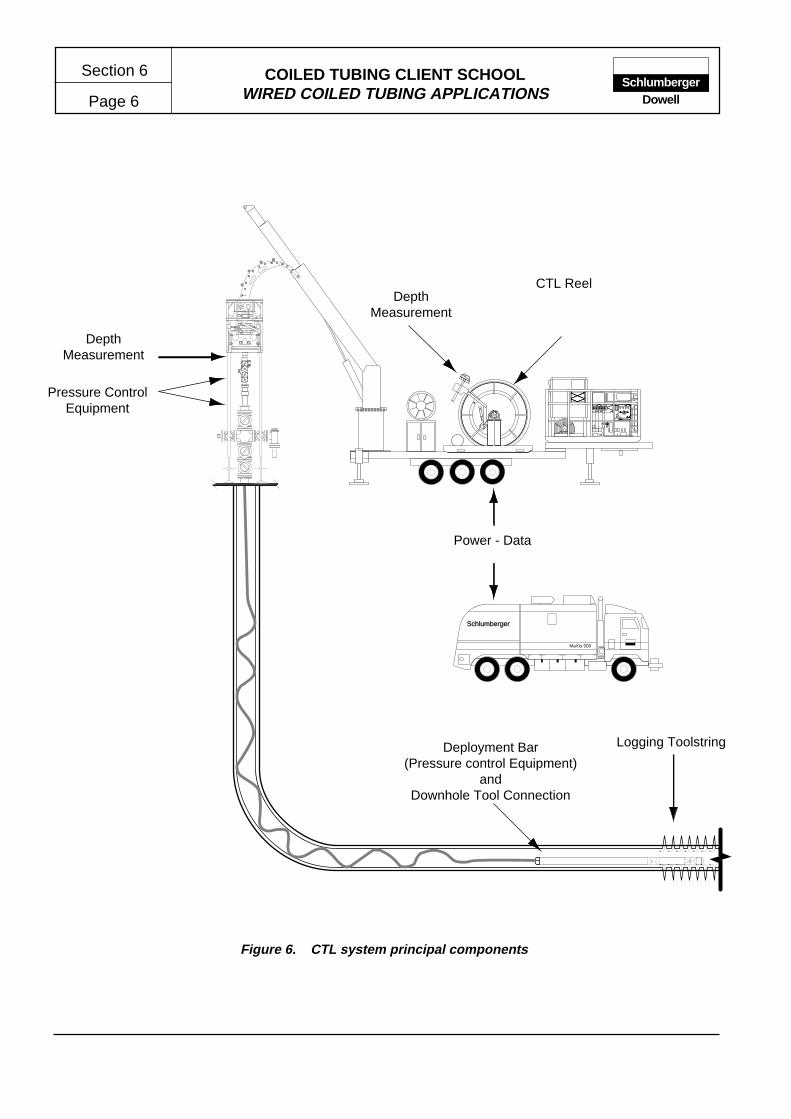
COILED TUBING CLIENT SCHOOLWIRED COILED TUBING APPLICATIONS
Section 6
Page 6Schlumberger
Dowell
High CoolantTemperature
High ExhaustTemperature
Low OilPressure
Loss of Coolant
Coolant Temperature
OilPressure
Engine Tachometer
AirPressure
Permissive start
EngineKill
EmergencyKill
Start
����������
��
Schlumberger
MaXis 500
CTL Reel
Logging ToolstringDeployment Bar(Pressure control Equipment)
andDownhole Tool Connection
Power - Data
DepthMeasurement
Pressure ControlEquipment
DepthMeasurement
Figure 6. CTL system principal components

COILED TUBING CLIENT SCHOOLWIRED COILED TUBING APPLICATIONS Page 7
Section 6Schlumberger
Dowell
2 COILED TUBING LOGGING APPLICATIONS
The installation of logging cable in a CT string hasextended logging capabilities in horizontal and deviatedwells, and allowed real time measurements whilepumping. The majority of CTL applications can becategorised as follows.
• Openhole logging
• Perforating
• Production logging
2.1 Openhole Logging
Openhole logging is principally a formation evaluationservice performed before setting casing or liner over theinterval of interest. In most cases, several tools areassembled and run simultaneously. The most commontools and their corresponding measurements are:
• Gamma ray - lithology identificationand correlation
• Dual induction - measures formation resistivity
• Litho density - measures porosity and identifies lithology
• Compensated neutron - measures porosity and iden-tifies lithology, locates gas and fluid contacts
• Sonic measurement - measures acoustic velocity forporosity and identifies lithology
• Stratigraphic - identifies bed orientation, fracture loca-tion, hole direction and geometry
• Rock sampling - provides side wall cores
• Fluid sampling - retrieves fluid samples under reservoirconditions and estimates permeability
• Borehole seismic - recovers seismic data.
There are two distinct types of application for openholeCTL:
• In highly deviated and horizontal wellbores where thetool string can no longer be lowered into the well bygravity
• Special applications in vertical wellbores.
2.1.1 Deviated and Horizontal Wellbores
In deviated wellbores, conventional openhole loggingoperations are performed by conveying the toolstring ondrillpipe. CT offers several advantages over thistechnique:
• shorter trip times
• continuous logging can be performed (up and down)with better speed and depth control
• the logging cable is protected within the CT
• the toolstring is less likely to be damaged by excessivecompressive forces which may be exerted when con-veyed on drill pipe.
The distance that a toolstring may be pushed along ahorizontal wellbore is dependent on several factors. Aprincipal factor being the weight and correspondingfriction of the toolstring in the wellbore.
Open tool suites are generally large (3-3/8-in. OD) andheavy. This combined with the relatively high frictionencountered in the open hole section can limit the reachwhich may be expected during openhole CTL operations.
The CoilCADE tubing forces model calculates the forcesand resulting stresses being applied to the CT as it isbeing run into and out of the well. This model is used inthe design of every CTL job to predicted limits ofoperation.
• How far the tools can be pushed into the highlydeviated or horizontal section of the well.
• What the weight indicator reading should display to theoperator during these operations.
• What the maximum stress will be in the CT during theseoperations.
The maximum possible depth of penetration is reachedwhen CT lock-up occurs. At this point, further injectionof tubing will only result in increasing the buckling of CTin the wellbore. This may be observed on the CT weightindicator display as a rapid loss of weight

COILED TUBING CLIENT SCHOOLWIRED COILED TUBING APPLICATIONS
Section 6
Page 8Schlumberger
Dowell
2.1.2 Vertical Wellbores
When logging on cable, the cable stretch and toolstringdrag can, under certain conditions, combine to create aslight yo-yo effect at the toolstring while logging. Whilein normal operations this is generally considered minimaland insignificant, it can be an important consideration inapplications which require a high degree of depth control.
Since the CT has a higher tensile strength than normallogging cables, CTL is often considered as viable inapplications which carry a high risk of stuck toolstrings,e.g., when logging highly permeable formations wherethe risk of differential sticking is high. Similarly, therigidity of the tubing can be used to push tools past minorwellbore restrictions. The ability to circulate fluid throughthe CT can be an advantage in applications that requireclean operating conditions.
2.1.3 Equipment Configuration
Open hole logging tools generally require the use ofheptacable to receive power and transmit data. At thedownhole end, the cable and CT are attached to thecoiled tubing head adaptor (CTHA). This adapterconnects the cable electrically, and the CT mechanically,to the logging toolstring. A mechanical weak point andfishing neck incorporated within the CTHA allow forcontingency release and retrieval of the toolstring in theevent of an emergency.
The most important measurement made during anylogging operation is depth. Encoders mounted on theCT injector head are connected to the CT unit controlcabin and the logging unit.
2.2 Perforating
The use of coiled tubing to convey perforating guns is anextension of established coiled tubing logging services.The rigidity and strength of CT can be used whenperforating highly deviated and horizontal intervals andwhen long and heavy gun assemblies are deployed. Inaddition, the configuration of CT pressure controlequipment allows perforating to be easily and safelyperformed on live or underbalanced wells.
2.2.1 Gun selection
Several types of perforating guns are used inconventional perforating operations. These may bebroadly categorized by type of application.
• Casing guns – These guns are larger (e.g., 3-3/8-in. to7-in. OD) which are conventionally conveyed on wirelineor tubing/drill pipe (TCP).
• Through-tubing guns – Because of the size restrictionsassociated with through-tubing work, such guns aregenerally 1-11/16-in. to 2-7/8-in. OD.
The most common perforating guns used with CT are ofthe through-tubing type as this is the application forwhich CT-conveyed perforating is commonly used.
An additional subdivision of through-tubing guns reflectsthe recoverability of the fired gun system.
• Expendable guns – Used in applications where debrisof large size and volume can be tolerated.
• Semi-expendable guns – Semi-expendable guns,used in applications where moderate debris can betolerated.
• Retrievable guns – Retrievable guns are containedwithin a rugged hollow carrier which confines the gundebris after firing. In addition to providing better retrieval,the carrier also allows the guns to be used at highertemperature and pressure.
Hollow gun carriers tend to swell as a result of theextreme pressures encountered during perforating.Therefore, the anticipated OD of the gun system afterfiring must be compatible with the minimum restrictionin the wellbore.
2.2.2 Perforation Charges
The productivity, and therefore effectiveness, of a per-forated interval depends greatly on the geometry of theperforations. There are several factors that determinethe efficiency of flow through a perforated completion.
• Perforations must extend beyond the zone surroundingthe wellbore which has been damaged by drilling mudand cement filtrate.
• Perforations must be cleaned of charge and formationdebris resulting from the perforating operation. This isbest accomplished by perforating in underbalanceconditions to enable all perforations clean upimmediately after firing.
• The density of perforations, i.e. shots per foot (SPF),must be carefully selected to avoid excessive pressure
COILED TUBING CLIENT SCHOOLWIRED COILED TUBING APPLICATIONS Page 9
Section 6Schlumberger
Dowell
drop at the perforation. This is largely determined byformation characteristics. For example, in layeredformations with relatively poor vertical permeability, ahigher shot density will be required.
Shot phasing is desirable to optimise productivity andmaintain casing or liner strength.
• In most applications a perforation diameter of 3/8-in. isconsidered adequate to allow easy clean up and avoidpremature plugging with asphalt or scale. Completionswhich are to be gravel packed require evenly spacedholes of around 3/4-in. to minimize the pressure dropacross the packed perforation tunnel.
The relative importance of each factor is dependent onthe type of completion, formation characteristics, andthe extent of formation damage caused by drilling andcementing operations. A computer model (SPAN**) hasbeen developed to predict the outcome of any perforationjob, allowing the completion engineer to compare alter-natives.
2.2.3 Firing Mechanism
Two means of firing the guns are applicable to CT-conveyed perforating. Electrical firing using a CTL stringor pressure activated firing initiated by applied internalpressure in the CT string.
Pressure firing systems may be used without the needfor a cable in the CT string, but suffer a distinctdisadvantage in that correlation logging tools cannot berun to confirm the location of the guns.
The conventional electrical detonators used in wirelineperforating operations are susceptible to detonationcaused by induced currents from stray voltage sources.Stray voltage can originate from many sources, e.g.,faulty electrical equipment, welding equipment, cathodicprotection equipment and radio frequency (RF)transmission. Therefore, adequate safety precautionsmust be taken to eliminate such sources beforeperforating operations can commence.
The Slapper-Actuated Firing Equipment, or S.A.F.E.*
firing system, has been developed as a firing systemwhich is protected from the effect of stray voltage.
2.3 Cased Hole Logging
Cased hole logging is principally an evaluation servicewhich confirms or identifies characteristics of the reservoiror completion. The most common activities includeproduction logging, cement evaluation and corrosionlogging.
• Production logging – measurement of temperature,pressure, density, flow velocity; may include fluidsampling, noise tool and gravel-pack tool
• Reservoir monitoring – gamma ray spectroscopy andthermal decay time logs
• Corrosion monitoring – multifinger caliper, boreholeteleviewer
• Cement evaluation – cement bond log, cement evalu-ation tool, ultrasonic imaging tool.
• Gyro compass
• Free point indicator
• Downhole seismic array
The majority of cased hole logging operations areconducted on completed wells which are producing.Therefore, the need exists for pressure control equipmentand associated operating procedures. Standard CTequipment and procedures can fulfill these requirementsand provide advantages and features exclusive to theCTL service.
CTL services are suited for several types of cased holeapplications:
• highly deviated and horizontal wellbores where the toolstring can no longer be lowered into the well by gravity
• vertical well applications where a high degree of depthand speed control is required
• applications that exploit the ability to pump through theCT while simultaneously logging
* Mark of Schlumberger
COILED TUBING CLIENT SCHOOLWIRED COILED TUBING APPLICATIONS
Section 6
Page 10Schlumberger
Dowell
2.3.1 Deviated and Horizontal Wellbores
The principal objective of production logging in horizontalwells is to determine the flow profile and productivityintervals along the wellbore ( i.e., what intervals orfractures are producing, what fluids are being producedand how much is each interval producing). The resultingflow profile is correlated with lateral variations inpermeability, saturation, etc., to detect productionanomalies (e.g. crossflow). By performing simultaneouspressure and rate transient tests the well and reservoirparameters can be quantified.
The information obtained from such an operation canthen be used to design the workover or remedialtreatment required to obtain optimum production fromthe well.
The acquisition and interpretation of data from horizontalwells can be complex and difficult. This difficulty is dueprimarily to the behavior of wellbore fluids and theoperation of logging tools in a horizontal wellbore profile.For example, multiphase fluids tend to segregate withheavier, slower moving fluids gravitating to the bottomof the wellbore. In such segregated flow regimes,advanced interpretation techniques are required to obtainaccurate fluid velocity measurements. In addition, someconventional logging tools measure fluid density bycomparing two pressure measurements made at a fixedvertical distance apart. In highly deviated or horizontalwellbores such measurements are no longer valid.
The challenge brought by such conditions has resultedin the development of sensors, tool string combinations,operating techniques and advanced interpretation skillsspecifically designed for horizontal applications.
Tools which measure the compression or tension appliedto the tool string may be used on logging operations.These tools provide a means of monitoring the progressof the tool string along the wellbore.
2.3.2 Vertical applications
The strength and rigidity of the CT, together with thespeed and depth control associated with CTL servicesoffers several advantages over conventional techniquesin vertical wellbores. The ability of CT equipment to besafely used on live and flowing wells is an additionaladvantage.
2.3.3 Simultaneous Pumping Applications
By conveying logging tools on a tube, simultaneouspumping and logging operations are possible. Thistechnique provides the basis for LiftLOG* serviceswhich pump nitrogen to initiate and maintain production.This ability allows production logs to be made of non-eruptive wells.
Historically, production logs of such wells have not beenpossible because the pumping device must be removedto allow passage of the logging tools. With the pumpremoved, the well does not flow and production loggingis not possible. By using LiftLOG services, the well isartificially lifted with nitrogen while the producing intervalis logged.
3 REFERENCES
The following references are recommended for jobdesign information or for further reading.
Technical Papers
Newman, K.R., et al, "Assisted Lift Production Loggingwith Coiled Tubing" OSEA 90142 Presented at theeighth Offshore South East Asia Conference, Singapore(December 1990)
Cooper, R.E.: “Coiled Tubing in Horizontal Wells”, SPEPaper 17581, International Petroleum EngineeringMeeting, Tianjin, China. November 1988.
Mason, O.L.: “Production Logging in a Rod-PumpedWell Using Coiled Tubing-Conveyed Tools and NitrogenGas Lift”, SPE Paper 22404, SPE International PetroleumEngineering Meeting, Beijing, China. March 1992.
Corrigan, M., C. Hoyer, C. Gaston: Logging on CoiledTubing: A Proven Technique for Highly Deviated Wellsand Other Applications”, SPE Paper 21314, April 1991.
MacEwan, H: “Coiled-Tubing-Conveyed LoggingSystems”, SPE Paper 18350, SPE European PetroleumConference, London, U.K. October 1988.
Howell, E.P., L.J. Smith, C.G. Blount: “Coiled TubingLogging System”, SPE Paper 15489, SPE TechnicalConference, New Orleans, Louisiana. October 1986.
Blount, C.G., E.Walker: “Coiled Tubing Operations andService - Part 6 - Tubing Assisted Logging andPerforating”, World Oil Coiled Tubing Handbook.
Section 7
Page 1COILED TUBING CLIENT SCHOOL MANUAL
COILED TUBING COMPLETIONS
1 COILED TUBING COMPLETIONS .............. 11.1 CT Completion Evolution/History ...... 11.2 CT Completion Benefits .................... 11.3 Types of CT Completion .................... 3
1.3.1 Velocity String Installations ..... 31.3.2 Externally Upset Completions . 41.3.3 SPOOLABLE Completions ...... 4
2 COMPLETION APPLICATIONS .................. 52.1 Artificial Lift Completions .................. 52.2 Remedial Completions ...................... 52.3 Completion of CTD Wellbores ........... 52.4 Candidate Wells ................................ 52.5 Constraints of CT Completions ......... 6
3 COMPLETION COMPONENTS .................. 63.1 CT Connectors .................................. 6
3.1.1 Connector Externally Upset ..... 63.1.2 External Connector – With Packing ....................... 73.1.3 Internal Connector – Spoolable ............................. 8
3.2 Gas Lift Valves and Mandrels ........... 9
ContentsPageContents Page
SchlumbergerDowell
3.2.1 Gas Lift Valve –Externally Upset .................. 93.2.2 Gas Lift Valves – Spoolable ........................... 10
3.3 CTS – TRSP Safety Valve .............. 113.4 Surface Equipment Rig-Up
(Externally Upset) ............................ 123.5 Surface Equipment Rig-Up
(Spoolable) ...................................... 134 COMPLETION DESIGN AND
ENGINEERING .......................................... 144.1 Nodal Analyses ............................... 144.2 Dimensional Criteria ........................ 144.3 Tubing Forces and Movement ......... 144.4 Hardware Selection Process ........... 144.5 Material Selection ............................ 154.6 Corrosion, H2S Embrittlement
and Stress Cracking ........................ 154.7 Well Preparation .............................. 154.8 Perforating ....................................... 154.9 Safety and Environment .................. 15
1 COILED TUBING COMPLETIONS
The development of larger OD (>2 in.) coiled tubing(CT) has increased the utility of CT as a completionconduit. This combined with the inherent advantages oflive well operations permitted by CT equipment, hasfurther increased interest and development efforts.
The economic advantages offered by completions whichmay be run and retrieved without the requirement for arig led CAMCO to a three year development and testingprogram. The culmination of this program is a CTcompletion system which is not only a viable–butprovides an attractive alternative to conventional jointedtubular completions.
The definition of coiled tubing completions may bestated as:
Completions which utilize coiled tubing as a wellboretubular, or as a means of conveying and installingcompletion equipment or tools.
1.1 CT Completions History/Evolution
In addition to innovative CT completion technology,there exists a significant role for CT in completions whichare adapted from, and use, conventional technology. Anoverview of the histroy and evolution of coiled tubingcompletions is shown in Fig. 1
1.2 CT Completion Benefits
Time and economy are the principle benefits which aredriving CT completion development. However, some CTcompletion applications offer the flexibility to increase, orsustain production (velocity strings). This combined withthe elimination of the costs and potential reservoir damageassociated with killing the well, ensures the attractivenessof many CT options.
• Time – Rapid mobilization, installation and retrieval–one day in and one day out are the goals of many CTcompletions.

COILED TUBING CLIENT SCHOOLCOILED TUBING COMPLETIONS
Section 7
Page 2Schlumberger
Dowell
History/Evolution of Coiled Tubing Completions
1969 Coiled tubing used as a workstring
1970 1-in. CT introduced
1978 1-1/4-in. CT introduced
1982 CT production instalations (Canada)
1986 1-1/2-in. CT introduced
1986 CT hanger (Wellhead Spool) developed
1988 1-3/4-in. introduced, CT installed for gas and inhibitor injection,CT production packer introduced
Coiled Tubing Completions – The last 5 years
1989 2-in. CT introduced, Continuous strings (bias weld)
1989 Camco patent filed
1990 2-in. CT installed as production string
1990 2-3/8 and 2-7/8-in. CT introduced
1992 3-1/2. CT introduced
1992 ESP installed on coiled tubing
1993 SPOOLABLE™ completions introduced
1994 ESP on CT with internal cable
Fig. 1. History and evolution of coiled tubing completions.
In addition to the rapid deployment of the initialcompletion string, the duration of future workovers willalso be reduced.
• Economy – The cost of most completion activities isgenerally directly related to the time required. In difficultor hostile environments there are additional cost factorswhich must also be considered, e.g., equipment andrigs suitable for arctic operations is extremelyexpensive. The ability to run a completion string withoutthe requirement for a specialized worover or servicerig provides significant economic benefits.
In many wellsites, the drilling rig or derrick has beenremoved, e.g., offshore. The cost of providing atemporary drilling or workover rig may not be a viableoption for conventional jointed completion types.
Live well intervention dispenses with the need forpotentially significant well kill procedures. Similarly,well kick-off procedures and equipment are notrequired.
• Reduced risk of reservoir damage – Many reservoirs,particularly reservoirs which are depleted, areextremely intolerant of kill fluids. Severe formation

COILED TUBING CLIENT SCHOOLCOILED TUBING COMPLETIONS Page 3
Section 7Schlumberger
Dowell
†Mark of CAMCO
damage may result from any attemt to workover orrecomplete the well. In such applications, the ability torun a coiled tubing completion without killing the wellmay be an attractive option.
There is an increasing awareness of reservoir damageand its implications. It is generally accepted thatprevention is easier and generally economically betterthan any attempt to cure.
1.3 Types of CT Completion
There are three main categories of coiled tubingcompletion.
• Velocity string installations
• Externally upset CT completion
• SPOOLABLE† CT completions
In the earliest completion applications, coiled tubingwas installed in existing production tubing as siphon orvelocity strings. This concept later expanded to includegas lift applications with, in its simplest from, the coiledtubing providing a single point gas injection system.
The efficiency of such gas lift applications is low whichled to the development of a gas lift system which utilizedexisting gas lift technology and equipment adapted forcoiled tubing completions. This has been refined to thereliable external upset coiled tubing completion detailedbelow.
A logical developement of this technology marraige wasto design and build a completion string with componentswhich could be passed through the coiled tubing andpressure control equipment. As a result SPOOLABLEcoiled tubing completions and accessories have beendesigned.
Coiled tubing completions are best suited to applicationswhich allow operators to take the maximum advantageof the inherent benefits CT can provide.
Note: Spoolable is a trademark of CAMCO
1.3.1 Velocity String Installations
• Predominantly gas well application
• Improve wellbore hydraulics
Original productiontubing
Coiled tubing
Production packer
Pump-out check valveor plug
Fig. 2. Velocity string installation
• Significant and sustained productionincreases from marginal wells
• Pump out plug or check allows live wellinstallation (Fig. 2.)
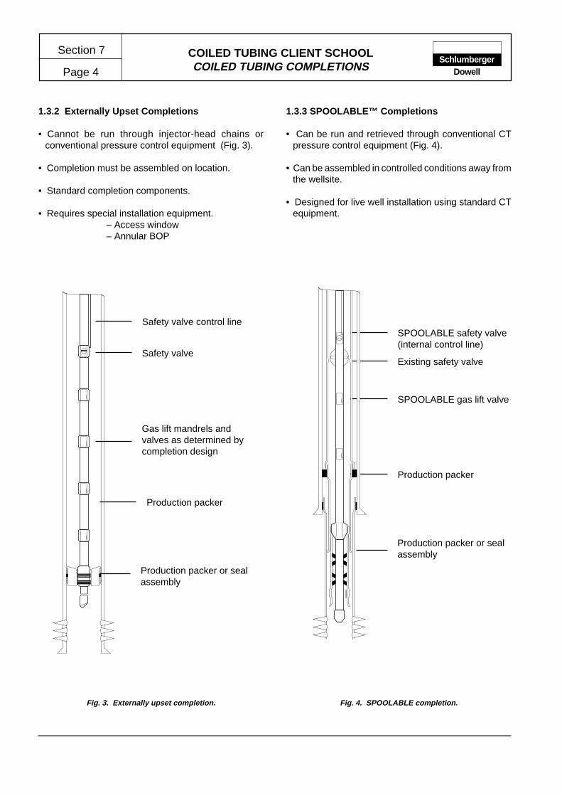
COILED TUBING CLIENT SCHOOLCOILED TUBING COMPLETIONS
Section 7
Page 4Schlumberger
Dowell
1.3.2 Externally Upset Completions
• Cannot be run through injector-head chains orconventional pressure control equipment (Fig. 3).
• Completion must be assembled on location.
• Standard completion components.
• Requires special installation equipment.– Access window– Annular BOP
Production packer or sealassembly
Gas lift mandrels andvalves as determined bycompletion design
Production packer
Safety valve control line
Safety valve
Fig. 3. Externally upset completion.
1.3.3 SPOOLABLE™ Completions
• Can be run and retrieved through conventional CTpressure control equipment (Fig. 4).
• Can be assembled in controlled conditions away fromthe wellsite.
• Designed for live well installation using standard CTequipment.
Existing safety valve
SPOOLABLE gas lift valve
Production packer
Production packer or sealassembly
SPOOLABLE safety valve(internal control line)
Fig. 4. SPOOLABLE completion.

COILED TUBING CLIENT SCHOOLCOILED TUBING COMPLETIONS Page 5
Section 7Schlumberger
Dowell
2 COMPLETION APPLICATIONS
Types of Coiled Completion
• Primary completions
• Artificial lift completions
• Remedial completions
• Special service completions
• CTD completions
2.1 Artificial Lift Completions
• Gas lift– Externally upset– SPOOLABLE™
• Electric submersible pumps– External cable– Internal cable
2.2 Remedial Completions
• Velocity string
• Sand control
• Tubing/casing repair
• Concentric injection string
2.3 Completion of CTD Wellbores
• Well deepening
• Sidetrack
• Multiple drainholes
CTD Completion Characteristics
• Small-diameter wellbore
• Operations performed thru-tubing
• Live well operations
• Deviated wellbore
• Multiple wellbores
• Moderate to severe dog-legs
• Depleted reservoir
• Unstable formations
2.4 Candidate Wells
Completion/Recompletion Applications
• Initial installations– Slimhole completions– Under economic justification
• Improving production hydraulics– Velocity string– Reduce the required gas injection rate– Installing gas lift in depleted reservoirs
Remedial Applications
• Remedial installations– Thru-tubing gravel pack– Casing/tubing repair and zonal isolation– Re-instate safety valve function
• Difficult pulling jobs– Dual completions– Failed gravel packs–Collapsed casing
Reservoir and Economic
• Special kill fluid requirements– Heavy (and costly) kill fluid required– High risk of formation damage
• Economic– Marginal wells where rig costs cannot be justified– Applications or locations requiring special rig configuration

COILED TUBING CLIENT SCHOOLCOILED TUBING COMPLETIONS
Section 7
Page 6Schlumberger
Dowell
2.5 Constraints of Coiled Tubing Completions
• Increased Xmas tree height
• Weight and handling (especially offshore)
• Completion-bore obstructed by components
• Components not generally suitable for “sand” service
• Coiled tubing material equivalent to L-80 or N-80 APIgrade materials
3 COMPLETION COMPONENTS
• Production string(s)
• Connectors
• Gas lift valves
• Packers
• Nipples and landing profiles
• Flow control devices
• Circulation devices
• Pumps
• Installation equipment
3.1 Coiled Tubing Connectors
• External Connector
• Single O-ring
• Dual O-ring
• Packing element seal
• Internal Spoolable™ connector
3.1.1 Connector – Externally Upset
• Compact design
• Simple assembly
• High strength
• Utility applications
• O-ring seal suitable for applications with minimaltubing OD deformation (Fig. 5)
�
�
�
������
������
�
�
�
�
�����
�
��
��
��
�
�
�
�
�
�
�
�
��
��
��
�
Connector body
Dual O-ring
Slip lock
Slip housing
Tool joint cut asrequired
Fig. 5. External connector – dual O-ring.

COILED TUBING CLIENT SCHOOLCOILED TUBING COMPLETIONS Page 7
Section 7Schlumberger
Dowell
3.1.2 External Connector – With Packing
• Energized seal separate from slip mechanism
• Sealing arrangement tolerant of ovality and deformation
• Mechanism compensates for thermal expansion andcontraction (Fig. 6).
�
�
�
����
����
�
������
�
��
�
�
�
�
��
������
��
��
�
�
�
�
�
�
��
��
�
����
����
Slip housing
Threaded ring
Belleville washers
Packing arrangement
Body
Fig. 6. External connector – packing element seal.

COILED TUBING CLIENT SCHOOLCOILED TUBING COMPLETIONS
Section 7
Page 8Schlumberger
Dowell
���������
���������
��������
���������
�
��
��
��
��
�
�
�
�
�
�
�
�
�
�
��
��
��
��
��
���
���
��
�
�������������
Slip lock
Body
Dual O-ring seals
Fig. 7. SPOOLABLE connector.
3.1.3 Internal Connector – Spoolable
• Alternative to welding when assembling completionstrings (Fig. 7).
• Can be passed through pressure control equipmentand spooled
• Slip grip increases with tension

COILED TUBING CLIENT SCHOOLCOILED TUBING COMPLETIONS Page 9
Section 7Schlumberger
Dowell
3.2 Gas Lift Valves and Mandrels
• External upset mandrels
– Sidepocket– KBMG or KBMM mandrels (4.50-in. min ID)
– Slimhole–CT-40 or CT-50 mandrels (under 4.50 in. ID)
– Internal Spoolable™ mandrels and valves
���������������������������������������
Orienting sleeve
Discriminator
Offset valve housing
Tool joints compatible withexternal connector threads
3.2.1 Gas Lift Valve – Externally Upset
• Conventional gas lift equipment – proven design
• Serviced by conventional slickline tools and techniques
• Slimhole and sidepocket mandrels (Fig. 8).
Fig. 8. External gas lift mandrel.

COILED TUBING CLIENT SCHOOLCOILED TUBING COMPLETIONS
Section 7
Page 10Schlumberger
Dowell
Fig. 9. SPOOLABLE™ gas lift mandrel.
GLM
Bellows assembly
Gas lift valve
Nose piece
Tail plug
���������
�������
��
���
���
��
�
��
��
��
��
���������������������
���������������������
�
��
��
�
��
�������������������������
����������������������
��
���
���
���
��
��
���
���
���
�
������
��
���
���
��
��
���
��
����
���
���
�����
�������
���������
����������
��������
������
����
��
• Four production modes
– CTS-IInjection pressure operated, tubing production
– CTS-IAInjection pressure operated, annular production
– CTS-FFluid pressure operated, tubing production
– CTS-FAFluid pressure operated, annular production
3.2.2 Gas Lift Valves – Spoolable
• Production through CT or annulus
• Mandrel welded or jointed by SPOOLABLE™connectors
• Applicable for 1-1/2 to 3-1/2-in. CT (Fig. 9).

COILED TUBING CLIENT SCHOOLCOILED TUBING COMPLETIONS Page 11
Section 7Schlumberger
Dowell
Fig. 10. SPOOLABLE safety valve.
Power spring
Recessed flapper valve
Hydraulic mechanism
3.3 CTS–TRSP Safety Valve
• 2-3/8-in. OD (3-1/2-in. tubing)
• 1.467 in2 flow area
• Control line inside CT
• 5000 psi working pressure
• Curved flapper
• Verification tested (Fig. 10).
– Class 1 API 14A

COILED TUBING CLIENT SCHOOLCOILED TUBING COMPLETIONS
Section 7
Page 12Schlumberger
Dowell
3.4 Surface Equipment Rig-Up (External Upset)
• Access window provides a work area for coupling thecompletion components (Fig. 11).
• Annular preventer provides a well control barrier capableof sealing on varying diameter tubulars
Work window
Casing hanger
Coiled tubing hanger
Gate valve
Coiled tubing BOP
Annular BOP
Slip bowl
Injector head
Reel
Fig. 11. Surface equipment rig-up.

COILED TUBING CLIENT SCHOOLCOILED TUBING COMPLETIONS Page 13
Section 7Schlumberger
Dowell
3.5 Surface Equipment Rig-Up (Spoolable)
• Surface equipment rig-up comprises coiled tubing andpressure control equipment generally used forconventional coiled tubing service operations (Fig. 12).
Fig. 12. Surface equipment rig-up.
Injector head
Lubricator
Coiled tubing BOP
Gate valve
Coiled tubing hanger
Casing hanger

COILED TUBING CLIENT SCHOOLCOILED TUBING COMPLETIONS
Section 7
Page 14Schlumberger
Dowell
4 COMPLETION DESIGN AND ENGINEERING
4.1 NODAL Analyses
• Selection of tubulars with appropriate ID– liquid loading, velocity string applications
• Confirm suitability of completion components– restrictions or limitations to production
• Confirm perforation shot density– important on gravel-packed completions
• Forecast production capability for downstream designand engineering
4.2 Dimensional Criteria
• Depth/length– Yield criteria for tubing and completioncomponents
• Wall thickness–Taper configuration, completion weight, drift ID
• Well path–deviation– Installation force predictions and set-downweights
• Upsets and profiles– Installation, retrieval and service access
• Connections and tool joints– Compatibility and resulting restrictions
4.3 Tubing Forces and Movement
• Temperature– Changes in length and resulting stresses
• Pressure– Combined stresses for operating limits
• Weight– Set-down and hang-off weights
• Fluid gradients– Changes may effect pressure and weight factors
• Friction and applied force
4.4 Hardware Selection Process
• Optimize production
• Facilitate installation
• Simplify maintenance
• Enable stimulation and workover
• Provide for contingency
Fig. 13 Material comparison – chemical composition.
Coiled Tubing Material Jointed Tubing Material API-5CTASTM A606 Type 4 (Mod.) AISI 4130 L-80 Type 1
Element % Content % Content % Content
Carbon 0.100 to 0.150 0.280 to 0.330 0.430 MaxManganese 0.600 to 0.900 0.400 to 0.600 1.900 MaxPhosphorus 0.025 Max 0.025 Max 0.030 Max
Sulphur 0.005 Max 0.025 Max 0.030 MaxSilicon 0.30 to 0.90 0.200 to 0.350 0.450 MaxNickel 0.250 Max – 0.250 Max
Chromium 0.500 to 0.750 0.800 to 1.100 –Copper 0.150 to 0.400 – 0.350 Max
Molybdenum – 0.150 to 0.250 –
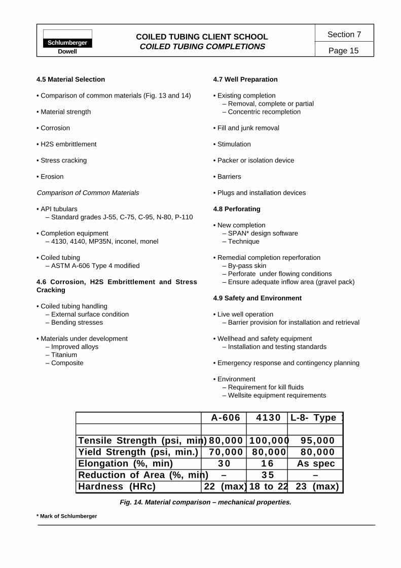
COILED TUBING CLIENT SCHOOLCOILED TUBING COMPLETIONS Page 15
Section 7Schlumberger
Dowell
4.5 Material Selection
• Comparison of common materials (Fig. 13 and 14)
• Material strength
• Corrosion
• H2S embrittlement
• Stress cracking
• Erosion
Comparison of Common Materials
• API tubulars– Standard grades J-55, C-75, C-95, N-80, P-110
• Completion equipment– 4130, 4140, MP35N, inconel, monel
• Coiled tubing– ASTM A-606 Type 4 modified
4.6 Corrosion, H2S Embrittlement and StressCracking
• Coiled tubing handling– External surface condition– Bending stresses
• Materials under development– Improved alloys– Titanium– Composite
4.7 Well Preparation
• Existing completion– Removal, complete or partial– Concentric recompletion
• Fill and junk removal
• Stimulation
• Packer or isolation device
• Barriers
• Plugs and installation devices
4.8 Perforating
• New completion– SPAN* design software– Technique
• Remedial completion reperforation– By-pass skin– Perforate under flowing conditions– Ensure adequate inflow area (gravel pack)
4.9 Safety and Environment
• Live well operation– Barrier provision for installation and retrieval
• Wellhead and safety equipment– Installation and testing standards
• Emergency response and contingency planning
• Environment– Requirement for kill fluids– Wellsite equipment requirements
* Mark of Schlumberger
Fig. 14. Material comparison – mechanical properties.
A-606 4130 L-8- Type 1
Tensile Strength (psi, min) 80,000 100,000 95,000Yield Strength (psi, min.) 70,000 80,000 80,000Elongation (%, min) 3 0 1 6 As specReduction of Area (%, min) – 3 5 –Hardness (HRc) 22 (max) 18 to 22 23 (max)
COILED TUBING DRILLING
ContentsContents Page Page
3.4.2 Creating Underbalance ............ 233.4.3 Controlling Underbalance ........ 243.4.4 Well Pressure Control .............. 243.4.5 Drilling Fluid ............................. 253.4.6 Wellbore Returns ..................... 253.4.7 BHA Deployment ..................... 253.4.8 Installing Completion Tubulars 26
3.5 Running Wellbore Tubulars ............... 264 SURFACE EQUIPMENT ........................... 27
4.1 Rigs and Structures for CTD.............. 274.1.1 CTD Substructures .................. 274.1.2 Location Requirements ............ 27
4.2 CT Equipment Package ..................... 294.3 Well Pressure Control Equipment ...... 294.4 Kick Detection Equipment .................. 32
4.4.1 Flow Comparison ..................... 324.4.2 Mud Tank Level Monitoring ..... 32
4.5 Mud System ....................................... 324.5.1 Mud Tanks ............................... 324.5.2 Mud Treatment Equipment ...... 34
4.6 Pumping Equipment .......................... 344.6.1 Low Pressure Equipment ......... 344.6.2 High Pressure Equipment ........ 34
4.7 Monitoring and Recording .................. 344.8 Pipe Handling Equipment .................. 354.9 Ancillary Surface Equipment .............. 354.10 Safety and Emergency Equipment .... 354.11 Equip. and Consumable Checklists ... 35
5 DOWNHOLE EQUIPMENT ....................... 355.1 Bits ..................................................... 39
5.1.1 Rock Bits .................................. 395.1.2 Drag Bits .................................. 40
5.2 Downhole Motors ............................... 415.2.1 Positive Displacement Motors . 41
5.3 CTD Downhole Equipment ................ 425.3.1 BHA for Vertical Wellbores ...... 425.3.2 BHA for Deviated Wellbores .... 42
5.4 Principal Directional Components ...... 425.5 Specialized CTD Tools ...................... 46
6 MANUFACTURERS AND SUPPLIERS..... 47
1 EVOLUTION OF CTD........................ 21.1 Advantages of CTD ........................... 2
1.1.1 Safety ......................................... 21.1.2 Economic ................................. 21.1.3 Operational .............................. 21.1.4 Environmental .......................... 21.1.5 Limitations and Disadvantages 2
1.2 CTD Applications ............................... 32 JOB DESIGN AND PREPARATION .......... 3
2.1 Establishing Objectives ...................... 32.2 Technical Feasibility .......................... 4
2.2.1 Weight on Bit ........................... 42.2.2 Annular Velocity ....................... 102.2.3 Pump Pressure and Rate ........ 132.2.4 CT String Tension .................... 132.2.5 Torque ..................................... 132.2.6 CT Life and Fatigue ................. 132.2.7 CT Reel Handling .................... 152.2.8 Directional Requirements ........ 15
2.3 CTD Project Preparation .................... 152.3.1 Technical Preparation .............. 152.3.2 Basic Equipment and Services 152.3.3 Procedures and Plans ............. 162.3.4 Drawings and Diagrams .......... 162.3.5 Personnel ................................. 162.3.6 Administrative Preparation ....... 16
3 EXECUTION .............................................. 173.1 Well Pressure Control ........................ 17
(Overbalanced Drilling) ...................... 173.2 Conventional Sidetracking ................. 17
3.2.1 Well Preparation ...................... 173.2.2 Setting the Whipstock .............. 183.2.3 Window Milling ......................... 18
3.3 Thru-tubing Reentry ........................... 193.3.1 Well Preparation ...................... 203.3.2 Tubing Whipstock .................... 203.3.3 Thru-tubing Whipstock ............. 213.3.4 Cement Kick-off Techniques .... 21
3.4 Underbalanced Drilling ...................... 233.4.1 Definition and Objectives ......... 23
Page 1
Section 8Schlumberger
Dowell
COILED TUBING CLIENT SCHOOL
COILED TUBING CLIENT SCHOOLCOILED TUBING DRILLING
Section 8
Page 2Schlumberger
Dowell
1 EVOLUTION OF COILED TUBING DRILLING
The techniques and equipment associated with coiledtubing drilling (CTD) have undergone rapid developmentsince the first operations attempted in 1991. A principalstimulus for this activity was the availability of reliablelarge diameter CT which enabled sufficient hydraulichorsepower to be delivered downhole. This energy isrequired to power the downhole motor and providesufficient flow rate to ensure adequate hole cleaningthrough efficient cutting transport. In addition, largerand heavier wall tubing provides the necessary weightfor efficient drilling and to safely withstand the torqueand fatigue imposed by drilling operations.
In 1991 Dowell established a coiled tubing drilling taskforce to utilize the expertise of several organisationswithin the Schlumberger group. Engineers from Sedco-Forex (drilling), Anadrill (MWD) and Dowell (coiledtubing) formed a group dedicated to the engineeringand development of CTD tools, equipment and practicesrequired to form an integrated CTD service package. Astep-by-step approach was adopted to ensure thatoperational capability was developed to support thenew tools and equipment.
1.1 Advantages of CTD
The factors, or advantages, associated with CTDwhich have provided the impetus for the servicedevelopment can be categorized as shown below.
• Safety
• Economic
• Operational
• Environmental
1.1.1 Safety
The configuration of the well control equipment used inCT operations provides a higher degree of control andsafety than that associated with conventional drillingequipment. This level of control is maintained throughoutdrilling and tripping operations. A large proportion ofaccidents are associated with pipe handling and themaking and breaking of tooljoints. With CTD, exposureto such hazards is much reduced.
1.1.2 Economic
Under the right conditions, CTD has the potential toprovide a general reduction in drilling and well costs.While this was a significant objective for early CTDattempts, it was seldom achieved due to the difficultieswhich are typically associated with an emergingtechnology.
The principal areas of cost saving in CTD are related tothe reduced hole size (slimhole) and wellsite area. Inaddition, CT units and equipment typically have lowermobilization and demobilization costs.
1.1.3 Operational
The safety advantage brought by CT well controlequipment enables underbalanced drilling operationsto be completed safely and efficiently. The principaladvantage of underbalanced drilling being reducedreservoir damage caused by the invasion of drilling fluidand cuttings.
Since the majority of CT services are performed throughthe production tubing, specialized thru-tubing CTD canbe undertaken with the completion tubulars in place.Well deepening and side-tracking of existing wells indepleted reservoirs is an area in which CTD offerssignificant operational and cost benefits comparedwith conventional drilling techniques.
Ultimately, it is intended that the techniques andequipment used in CTD will provide a level of controland response which will permit “joystick drilling”.
1.1.4 Environmental
In several locations, e.g., urban areas, minimizing thewellsite area, as well as the visual and noise impact, isa significant factor in the preparation and execution ofdrilling operations. The configuration of CT equipmentenables operations to be completed from a smallerwork site using equipment which is less visually intrusive.Additionally, operations using continuous tubing causesignificantly less noise pollution than those using jointedpipe.
1.1.5 Limitations and Disadvantages
The limitations and disadvantages of CTD can besummarized in the following categories.

COILED TUBING CLIENT SCHOOLCOILED TUBING DRILLING Page 3
Section 8Schlumberger
Dowell
Well Status
Wellbore Trajectory
Well Preparation
Wellbore Conditions
Reentry New wellor
Well finishing
Tubing/completionremoved
Through tubingoperation
Welldeepening
(No directionalcontrol)
Side track(Directional control)
Underbalanced Overbalanced
• Economic – in many areas, the abundance of low-costconventional rigs render the use of CTD for someapplications uneconomic. In such areas, onlyspecialized CTD techniques which cannot becompleted by conventional equipment will be viable.
• Hole size – the advantage of being able to drillslimhole is, in some applications, countered by theinability to drill larger hole sizes.
• Rotation – since the CT string cannot be rotated,steering adjustments in directional drilling applicationsmust be initiated using downhole tools.
• CT fatigue and life – although the fatigue and usefullife of CT strings are now well understood andmonitored, it can be difficult to accurately predict theextent to which a strings life may be used during anyCTD operation.
1.2 CTD Applications
There are several ways in which CTD applications havebeen classified. Most operations can be describedusing the following criteria (Fig. 1):
• Well status – new well or re-entry
• Well preparation – tubing/completion removed orthru-tubing
• Wellbore trajectory – well deepening or side track
• Wellbore conditions – underbalanced or overbalanceddrilling
The illustration in Fig. 2 shows the world wide trend inCTD from 1991 through 1994. In this period, two distinctareas of CTD operation were identified; operationswhich utilize the unique capability of CT and operationswhich could have been completed by conventionaldrilling techniques and equipment. It is generallyaccepted, that the increasing trend toward specializedapplications will continue as the reliability of thetechniques improve and the resulting benefits becomemore apparent.
2 JOB DESIGN AND PREPARATION
The job design and preparation sequence for CTDoperations comprises several distinct tasks or areas ofinvestigation.
• Establish the client's objectives
• Review the technical feasibility
• Technical preparation
• Administrative preparation
2.1 Establishing Objectives
Unlike most CT service activities, the overall objective(s)of the client may not always be immediately apparent,e.g., is the well being drilled for production, appraisal,delineation or exploration purposes? It is beneficial tothe overall process if all parties involved in the designand execution of the CTD operation are aware of theobjectives and goals associated with them. In addition,the means and criteria by which the achievement of theobjectives will be assessed should also be known.
Fig. 1 Classification of CTD applications.
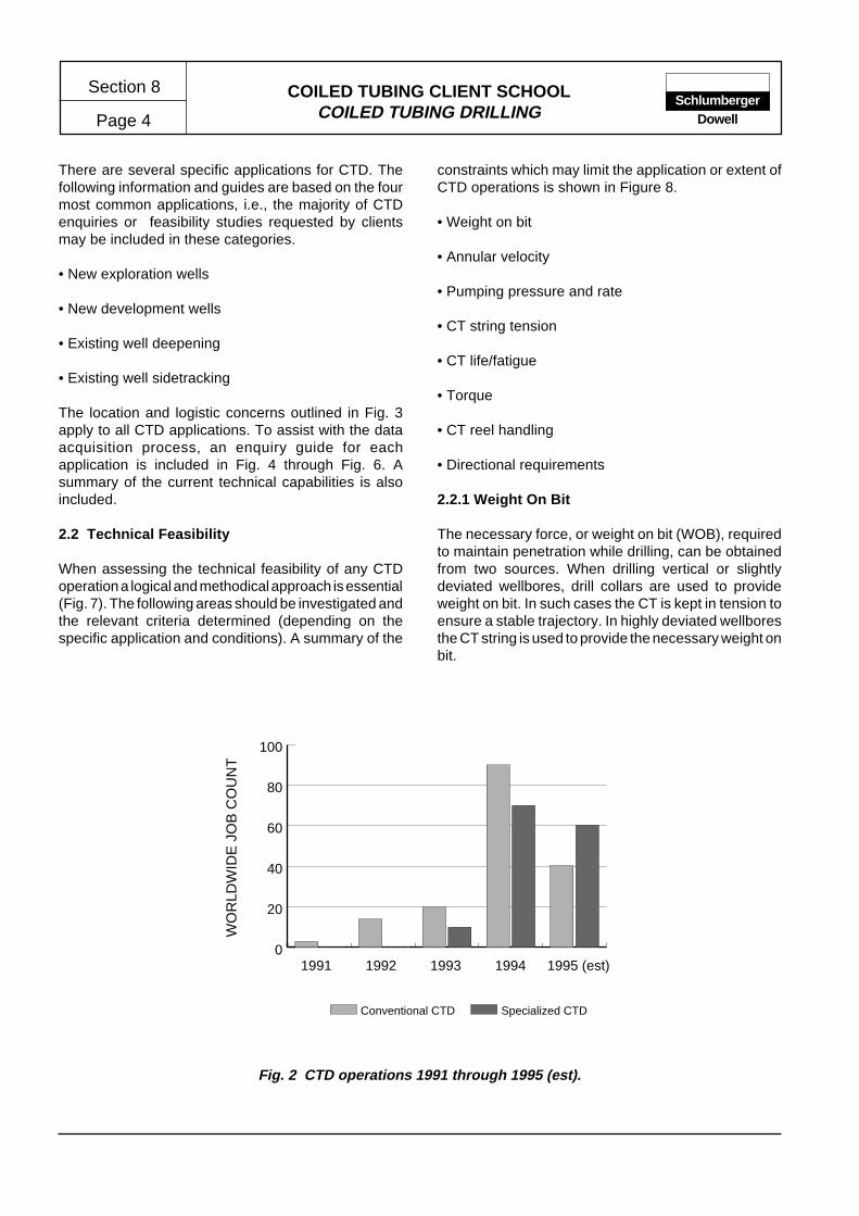
COILED TUBING CLIENT SCHOOLCOILED TUBING DRILLING
Section 8
Page 4Schlumberger
Dowell
Fig. 2 CTD operations 1991 through 1995 (est).
0
20
40
60
80
100
Specialized CTDConventional CTD
1995 (est)1994199319921991
WO
RLD
WID
E J
OB
CO
UN
T
There are several specific applications for CTD. Thefollowing information and guides are based on the fourmost common applications, i.e., the majority of CTDenquiries or feasibility studies requested by clientsmay be included in these categories.
• New exploration wells
• New development wells
• Existing well deepening
• Existing well sidetracking
The location and logistic concerns outlined in Fig. 3apply to all CTD applications. To assist with the dataacquisition process, an enquiry guide for eachapplication is included in Fig. 4 through Fig. 6. Asummary of the current technical capabilities is alsoincluded.
2.2 Technical Feasibility
When assessing the technical feasibility of any CTDoperation a logical and methodical approach is essential(Fig. 7). The following areas should be investigated andthe relevant criteria determined (depending on thespecific application and conditions). A summary of the
constraints which may limit the application or extent ofCTD operations is shown in Figure 8.
• Weight on bit
• Annular velocity
• Pumping pressure and rate
• CT string tension
• CT life/fatigue
• Torque
• CT reel handling
• Directional requirements
2.2.1 Weight On Bit
The necessary force, or weight on bit (WOB), requiredto maintain penetration while drilling, can be obtainedfrom two sources. When drilling vertical or slightlydeviated wellbores, drill collars are used to provideweight on bit. In such cases the CT is kept in tension toensure a stable trajectory. In highly deviated wellboresthe CT string is used to provide the necessary weight onbit.

COILED TUBING CLIENT SCHOOLCOILED TUBING DRILLING Page 5
Section 8Schlumberger
Dowell
Location
• What are the dimensional and deck load constraints for the operational, storage and fluid
handling areas?
Logistics
• Is a crane of adequate capacity available? Is it located in position which allows unrestricted
access to the well and operational areas? What are the load capacity and boom length?
• Where is the personnel accommodation?
Environment
• What provisions may be necessary to enable adequate environmental protection, e.g.,
noise, spill protection or temporary chemical storage?
• What local weather, sea, seasonal conditions may restrict operations?
CTD ENQUIRY GUIDE – LOCATION, LOGISTICS AND ENVIRONMENT
Onshore
Offshore
Location
• In which type of environment is the wellsite, e.g., urban area, jungle or desert?
• What are the location constraints, e.g., size, obstructions and obstacles?
Logistics
• Are there any known logistical constraints, e.g., limits to access, operational windows etc.?
Environment
• What provisions may be necessary to enable adequate environmental protection, e.g.,
noise, spill protection or temporary chemical storage?
Figure 3. CTD enquiry guide – location, logistic and environment.

COILED TUBING CLIENT SCHOOLCOILED TUBING DRILLING
Section 8
Page 6Schlumberger
Dowell
Figure 4. CTD enquiry guide –new exploration well
CTD ENQUIRY GUIDE – NEW WELLS & VERTICAL WELL DEEPENING
Exploration andproduction objectives
Wellbore design
• Is this an oil or gas well?
Data collection• How extensive is the logging program to be?• What are the mud logging requirements?• What is the minimum acceptable size of the productioncasing or liner ?
Hole sizeUp to 12-1/4-in. hole – for hole sizesgreater than 6-3/4-in. formations must beunconsolidated (motors OD:– 4-3/4-in. ormodified 6-1/2-in.)
DepthAchievable depth dependent on holesize and formation drillability (new wellCTD generally limited to 5,000 to 6,000 ftwith three or four casing strings.
Typical limitations• Torque tolerance of the CT string limits
the motor size.
• The CT pumping pressure limits the
depth of the hole sizes larger than 4-3/4-
in.
CT string size• 2-3/8-in. CT is recommended for hole
sizes greater than 6-3/4-in. or for 4-3/4-
in. sections deeper than 5,000 ft.
Wellbore geometry• What is to be the TD and open-hole sizes?• What is the casing program, i.e., casing size and shoe depths?
Deviation• If the wellbore is deviated, what is the projected well profile, i.e,
inclination and azimuth versus depth!
• What is the acceptable target tolerance fromprojected profile?
• If the wellbore is vertical, what is the maximum acceptable
deviation?
Downhole conditions• What are the formation pressures and temperature?• What is the well lithology?• Is there a risk of shallow gas?• Are there any sloughing shales?• What is the likelihood of H2S?
Operations
Bit and drilling performance• What is known of the formation(s) drillability ?• Are offset well bit records available?
Drilling fluid• Is the reservoir to be drilled under or overbalanced?
• What drilling fluid(s) is to be used, i.e., mud, foam or air?
• What are the properties of the mud system to be used, i.e., type,
density and characteristics?
• What is the likelihood of lost circulation?
Current Technical Capability

COILED TUBING CLIENT SCHOOLCOILED TUBING DRILLING Page 7
Section 8Schlumberger
Dowell
CTD ENQUIRY GUIDE – EXISTING WELL SIDETRACK REENTRY
Production andcompletion objectives
Wellbore design
Production• Is this an oil, gas or injection well?
Completion• What will be the liner size?• What is the minimum acceptable liner size?• Will the liner be cemented?• How is the new completion to be configured?
Wellbore geometry• What is to be the TD and open-hole sizes?• What are the existing casing sizes and shoe depths?
Deviation• What is the existing well profile, i.e, inclination and azimuth
versus depth?
• Which kick-off technique will be used, e.g., window or section
milling?
• What is the re-entry well profile, i.e., kick-off depth, build up
rate, inclination, azimuth and drain hole length?
• What is the acceptable target tolerance from projected profile?
Downhole conditions• What are the formation pressures and temperature?• What is the well lithology?• Are there any sloughing shales?• What is the likelihood of H2S
Current Technical Capability
Bit and drilling performance• What is known of the formation(s) drillability?• Are offset well bit records available?
Drilling fluid• Is the reservoir to be drilled under or overbalanced?
• What drilling fluid(s) is to be used, i.e., mud, foam or air?
• What are the properties of the mud system to be used, i.e., type,
density and characteristics?
• What is the likelihood of lost circulation or losses?
Operations
Hole sizeThrough-tubing• Minimum completion size of 4-1/2-in.,
allowing a 3-1/2- or 3-3/4-in. hole.
Conventional (completion removed)• Up to 4-3/4-in. with a build-up radius of up
to 60°/100ft.
• Up to 6-in. with a build-up radius of up to
15°/100ft.
Depth• Horizontal drainhole can exceed 2,000ft,
but is dependent on BUR, KOD, casing
and CT sizes.
Total depth• Through tubing: up to 15,000ft• Conventional (completion removed):
more than 10,000ft
Typical limitations• Build-up radius (BUR) limited by bending
friction force of the BHA which limits the
available WOB.
• Downhole WOB provided by the CT limits
the horizontal drainhole length
(CoilCADE check)
CT string size• 1-3/4- to 2-3/8-in. depending on the hole
profile
Figure 6. CTD enquiry guide – existing well sidetrack reentry.
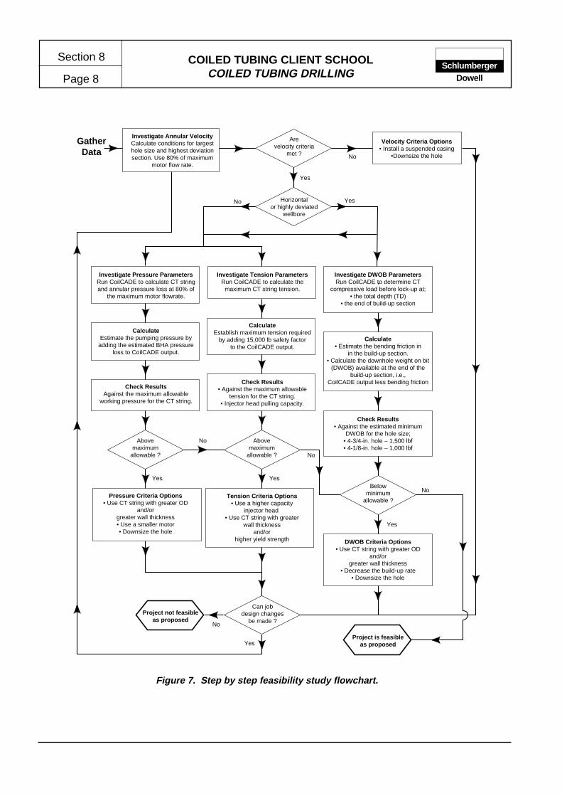
COILED TUBING CLIENT SCHOOLCOILED TUBING DRILLING
Section 8
Page 8Schlumberger
Dowell
Figure 7. Step by step feasibility study flowchart.
No
GatherData
Project is feasibleas proposed
Horizontalor highly deviated
wellbore
Arevelocity criteria
met ?
Can jobdesign changes
be made ?Project not feasible
as proposed
Investigate Pressure ParametersRun CoilCADE to calculate CT stringand annular pressure loss at 80% of
the maximum motor flowrate.
CalculateEstablish maximum tension required
by adding 15,000 lb safety factorto the CoilCADE output.
Check Results• Against the maximum allowable
tension for the CT string.• Injector head pulling capacity.
Tension Criteria Options• Use a higher capacity
injector head • Use CT string with greater
wall thicknessand/or
higher yield strength
CalculateEstimate the pumping pressure by
adding the estimated BHA pressureloss to CoilCADE output.
Check ResultsAgainst the maximum allowable
working pressure for the CT string.
Pressure Criteria Options• Use CT string with greater OD
and/orgreater wall thickness• Use a smaller motor• Downsize the hole
Investigate Annular VelocityCalculate conditions for largesthole size and highest deviationsection. Use 80% of maximum
motor flow rate.
Velocity Criteria Options• Install a suspended casing
•Downsize the hole
Abovemaximum
allowable ?
Investigate Tension ParametersRun CoilCADE to calculate the
maximum CT string tension.
Abovemaximum
allowable ?
Investigate DWOB ParametersRun CoilCADE to determine CT
compressive load before lock-up at;• the total depth (TD)
• the end of build-up section
Calculate• Estimate the bending friction in
in the build-up section.• Calculate the downhole weight on bit
(DWOB) available at the end of thebuild-up section, i.e.,
CoilCADE output less bending friction
Check Results• Against the estimated minimum
DWOB for the hole size;• 4-3/4-in. hole – 1,500 lbf• 4-1/8-in. hole – 1,000 lbf
DWOB Criteria Options• Use CT string with greater OD
and/orgreater wall thickness
• Decrease the build-up rate• Downsize the hole
Belowminimum
allowable ?
Yes
Yes Yes
No
No
Yes
No
Yes
No
YesNo
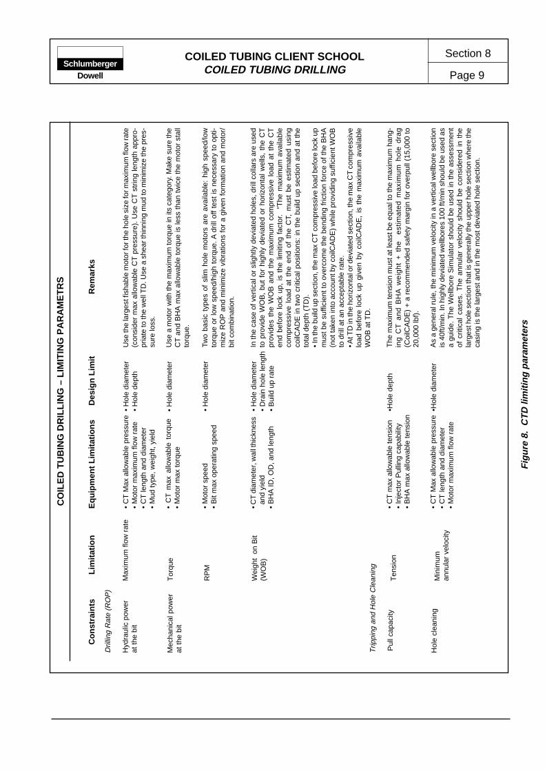
COILED TUBING CLIENT SCHOOLCOILED TUBING DRILLING Page 9
Section 8Schlumberger
Dowell
CO
ILE
D T
UB
ING
DR
ILLI
NG
– L
IMIT
ING
PA
RA
ME
TR
S
Use
the
larg
est f
isha
ble
mot
or fo
r the
hol
e si
ze fo
r max
imum
flow
rate
(con
side
r m
ax a
llow
able
CT
pre
ssur
e).
Use
CT
str
ing
leng
th a
ppro
-pr
iate
to th
e w
ell T
D. U
se a
she
ar th
inni
ng m
ud to
min
imiz
e th
e pr
es-
sure
loss
.
Use
a m
otor
with
the
max
imum
torq
ue in
its
cate
gory
. Mak
e su
re th
eC
T a
nd B
HA
max
allo
wab
le to
rque
is le
ss th
an tw
ice
the
mot
or s
tall
torq
ue.
In th
e ca
se o
f ver
tical
or
slig
htly
dev
iate
d ho
les,
dril
l col
lars
are
use
dto
pro
vide
WO
B,
but
for
high
ly d
evia
ted
or h
oriz
onta
l wel
ls,
the
CT
prov
ides
the
WO
B a
nd t
he m
axim
um c
ompr
essi
ve l
oad
at t
he C
Ten
d be
fore
loc
k up
, is
the
lim
iting
fac
tor.
“T
he m
axim
um a
vaila
ble
com
pres
sive
loa
d at
the
end
of
the
CT,
mus
t be
est
imat
ed u
sing
coilC
AD
E in
tw
o cr
itica
l pos
ition
s: in
the
bui
ld u
p se
ctio
n an
d at
the
tota
l dep
th (
TD
).• I
n th
e bu
ild u
p se
ctio
n, th
e m
ax C
T c
ompr
essi
ve lo
ad b
efor
e lo
ck u
pm
ust b
e su
ffici
ent t
o ov
erco
me
the
bend
ing
fric
tion
forc
e of
the
BH
A(n
ot ta
ken
into
acc
ount
by
coilC
AD
E)
whi
le p
rovi
ding
suf
ficie
nt W
OB
to d
rill a
t an
acce
ptab
le r
ate.
• At T
D in
the
horiz
onta
l or d
evia
ted
sect
ion,
the
max
CT
com
pres
sive
load
bef
ore
lock
up
give
n by
coi
lCA
DE
, is
the
max
imum
ava
ilabl
eW
OB
at T
D.
The
max
imum
tens
ion
mus
t at l
east
be
equa
l to
the
max
imum
han
g-in
g C
T a
nd
BH
A w
eig
ht
+ t
he
e
stim
ate
d m
axi
mu
m h
ole
dra
g(C
oilC
AD
E)
+ a
rec
omm
ende
d sa
fety
mar
gin
for
over
pull
(15,
000
to20
,000
lbf)
.
As
a ge
nera
l rul
e, th
e m
inim
um v
eloc
ity in
a v
ertic
al w
ellb
ore
sect
ion
is 4
0ft/m
in. I
n hi
ghly
dev
iate
d w
ellb
ores
100
ft/m
in s
houl
d be
use
d as
a gu
ide.
The
Wel
lbor
e S
imul
ator
sho
uld
be u
sed
in t
he a
sses
smen
tof
crit
ical
cas
es.
The
ann
ular
vel
ocity
sho
uld
be c
onsi
dere
d in
the
larg
est h
ole
sect
ion
that
is g
ener
ally
the
uppe
r hol
e se
ctio
n w
here
the
casi
ng is
the
larg
est a
nd in
the
mos
t dev
iate
d ho
le s
ectio
n.
• H
ole
diam
eter
• H
ole
dept
h
• H
ole
diam
eter
• H
ole
diam
eter
• D
rain
hol
e le
ngth
• B
uild
up
rate
•Hol
e de
pth
•Hol
e di
amet
er
• C
T M
ax a
llow
able
pre
ssur
e•
Mot
or m
axim
um fl
ow r
ate
• C
T le
ngth
and
dia
met
er•
Mud
type
, wei
ght,
yiel
d
• C
T m
ax a
llow
able
tor
que
• M
otor
max
torq
ue
• M
otor
spe
ed•
Bit
max
ope
ratin
g sp
eed
• CT
dia
met
er, w
all t
hick
ness
and
yie
ld•
BH
A ID
, OD
, and
leng
th
• C
T m
ax a
llow
able
tens
ion
• In
ject
or P
ullin
g ca
pabi
lity
• B
HA
max
allo
wab
le te
nsio
n
• C
T M
ax a
llow
able
pre
ssur
e•
CT
leng
th a
nd d
iam
eter
• M
otor
max
imum
flow
rat
e
Tor
que
RP
M
Wei
ght
on B
it(W
OB
)
Ten
sion
Min
imum
annu
lar
velo
city
Max
imum
flow
rat
e
Dril
ling
Rat
e (R
OP
)
Hyd
raul
ic p
ower
at th
e bi
t
Mec
hani
cal p
ower
at th
e bi
t
Con
stra
ints
Lim
itatio
nE
quip
men
t Lim
itatio
nsD
esig
n Li
mit
Rem
arks
Trip
ping
and
Hol
e C
lean
ing
Pul
l cap
acity
Hol
e cl
eani
ng
• H
ole
diam
eter
Two
basi
c ty
pes
of s
lim h
ole
mot
ors
are
avai
labl
e: h
igh
spee
d/lo
wto
rque
or
low
spe
ed/h
igh
torq
ue. A
dril
l off
test
is n
eces
sary
to
opti-
miz
e R
OP
and
min
imiz
e vi
brat
ions
for
a gi
ven
form
atio
n an
d m
otor
/bi
t com
bina
tion.
Fig
ure
8. C
TD
lim
iting
par
amet
ers
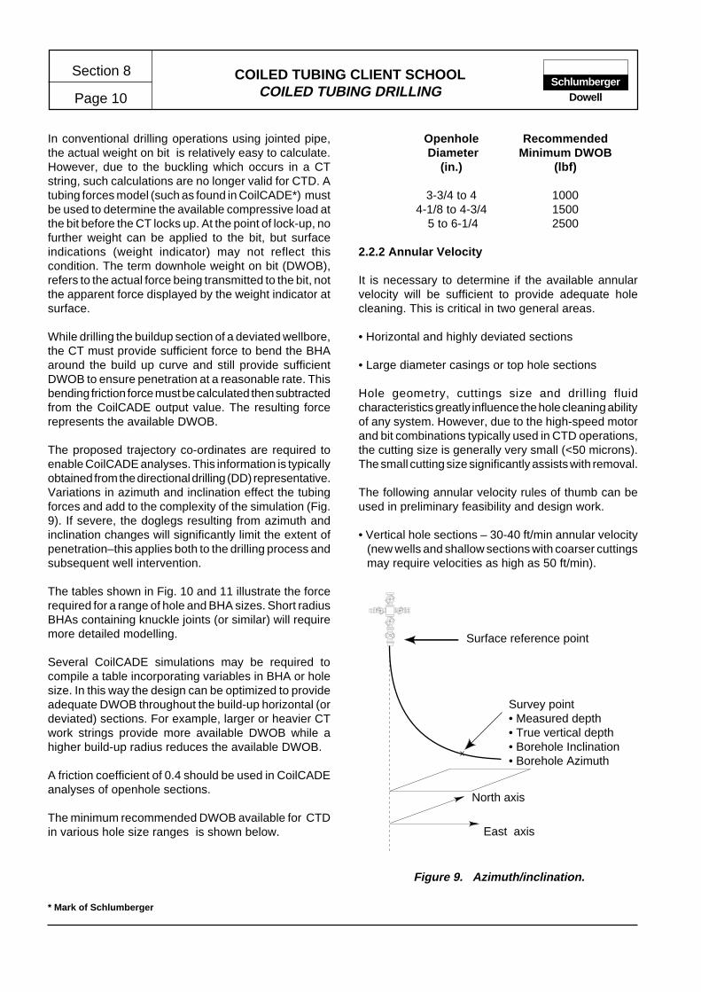
COILED TUBING CLIENT SCHOOLCOILED TUBING DRILLING
Section 8
Page 10Schlumberger
Dowell
* Mark of Schlumberger
Figure 9. Azimuth/inclination.
Survey point• Measured depth• True vertical depth• Borehole Inclination• Borehole Azimuth
Surface reference point
North axis
East axis
In conventional drilling operations using jointed pipe,the actual weight on bit is relatively easy to calculate.However, due to the buckling which occurs in a CTstring, such calculations are no longer valid for CTD. Atubing forces model (such as found in CoilCADE*) mustbe used to determine the available compressive load atthe bit before the CT locks up. At the point of lock-up, nofurther weight can be applied to the bit, but surfaceindications (weight indicator) may not reflect thiscondition. The term downhole weight on bit (DWOB),refers to the actual force being transmitted to the bit, notthe apparent force displayed by the weight indicator atsurface.
While drilling the buildup section of a deviated wellbore,the CT must provide sufficient force to bend the BHAaround the build up curve and still provide sufficientDWOB to ensure penetration at a reasonable rate. Thisbending friction force must be calculated then subtractedfrom the CoilCADE output value. The resulting forcerepresents the available DWOB.
The proposed trajectory co-ordinates are required toenable CoilCADE analyses. This information is typicallyobtained from the directional drilling (DD) representative.Variations in azimuth and inclination effect the tubingforces and add to the complexity of the simulation (Fig.9). If severe, the doglegs resulting from azimuth andinclination changes will significantly limit the extent ofpenetration–this applies both to the drilling process andsubsequent well intervention.
The tables shown in Fig. 10 and 11 illustrate the forcerequired for a range of hole and BHA sizes. Short radiusBHAs containing knuckle joints (or similar) will requiremore detailed modelling.
Several CoilCADE simulations may be required tocompile a table incorporating variables in BHA or holesize. In this way the design can be optimized to provideadequate DWOB throughout the build-up horizontal (ordeviated) sections. For example, larger or heavier CTwork strings provide more available DWOB while ahigher build-up radius reduces the available DWOB.
A friction coefficient of 0.4 should be used in CoilCADEanalyses of openhole sections.
The minimum recommended DWOB available for CTDin various hole size ranges is shown below.
Openhole Recommended Diameter Minimum DWOB
(in.) (lbf)
3-3/4 to 4 10004-1/8 to 4-3/4 1500
5 to 6-1/4 2500
2.2.2 Annular Velocity
It is necessary to determine if the available annularvelocity will be sufficient to provide adequate holecleaning. This is critical in two general areas.
• Horizontal and highly deviated sections
• Large diameter casings or top hole sections
Hole geometry, cuttings size and drilling fluidcharacteristics greatly influence the hole cleaning abilityof any system. However, due to the high-speed motorand bit combinations typically used in CTD operations,the cutting size is generally very small (<50 microns).The small cutting size significantly assists with removal.
The following annular velocity rules of thumb can beused in preliminary feasibility and design work.
• Vertical hole sections – 30-40 ft/min annular velocity(new wells and shallow sections with coarser cuttingsmay require velocities as high as 50 ft/min).
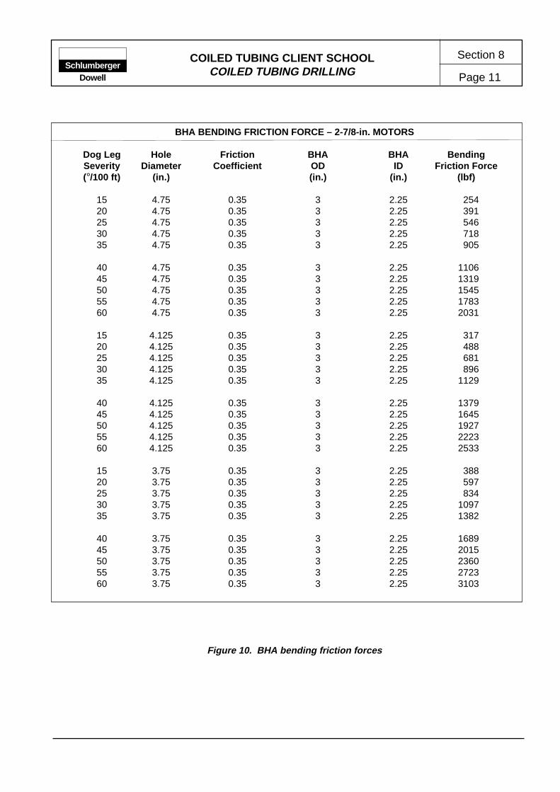
COILED TUBING CLIENT SCHOOLCOILED TUBING DRILLING Page 11
Section 8Schlumberger
Dowell
Figure 10. BHA bending friction forces
BHA BENDING FRICTION FORCE – 2-7/8-in. MOTORS
Dog Leg Hole Friction BHA BHA BendingSeverity Diameter Coefficient OD ID Friction Force(°/100 ft) (in.) (in.) (in.) (lbf)
15 4.75 0.35 3 2.25 25420 4.75 0.35 3 2.25 39125 4.75 0.35 3 2.25 54630 4.75 0.35 3 2.25 71835 4.75 0.35 3 2.25 905
40 4.75 0.35 3 2.25 110645 4.75 0.35 3 2.25 131950 4.75 0.35 3 2.25 154555 4.75 0.35 3 2.25 178360 4.75 0.35 3 2.25 2031
15 4.125 0.35 3 2.25 31720 4.125 0.35 3 2.25 48825 4.125 0.35 3 2.25 68130 4.125 0.35 3 2.25 89635 4.125 0.35 3 2.25 1129
40 4.125 0.35 3 2.25 137945 4.125 0.35 3 2.25 164550 4.125 0.35 3 2.25 192755 4.125 0.35 3 2.25 222360 4.125 0.35 3 2.25 2533
15 3.75 0.35 3 2.25 38820 3.75 0.35 3 2.25 59725 3.75 0.35 3 2.25 83430 3.75 0.35 3 2.25 109735 3.75 0.35 3 2.25 1382
40 3.75 0.35 3 2.25 168945 3.75 0.35 3 2.25 201550 3.75 0.35 3 2.25 236055 3.75 0.35 3 2.25 272360 3.75 0.35 3 2.25 3103

COILED TUBING CLIENT SCHOOLCOILED TUBING DRILLING
Section 8
Page 12Schlumberger
Dowell
BHA BENDING FRICTION FORCE – 3-1/2-in. MOTORS
Dog Leg Hole Friction BHA BHA BendingSeverity Diameter Coefficient OD ID Friction Force(°/100 ft) (in.) (in.) (in.) (lbf)
5 6 0,35 3.5 2.5 8210 6 0,35 3.5 2.5 23215 6 0,35 3.5 2.5 42620 6 0,35 3.5 2.5 65625 6 0,35 3.5 2.5 91630 6 0,35 3.5 2.5 120435 6 0,35 3.5 2.5 151840 6 0,35 3.5 2.5 185445 6 0,35 3.5 2.5 2213
5 4.75 0.35 3.5 2.5 11610 4.75 0.35 3.5 2.5 32815 4.75 0.35 3.5 2.5 60220 4.75 0.35 3.5 2.5 92725 4.75 0.35 3.5 2.5 129630 4.75 0.35 3.5 2.5 170335 4.75 0.35 3.5 2.5 214640 4.75 0.35 3.5 2.5 262245 4.75 0.35 3.5 2.5 3129
BHA BENDING FRICTION FORCE – 4-3/4 -in. MOTORS
Dog Leg Hole Friction BHA BHA BendingSeverity Diameter Coefficient OD ID Friction Force(°/100 ft) (in.) (in.) (in.) (lbf)
5 6 0.35 4.75 3 44710 6 0.35 4.75 3 126415 6 0.35 4.75 3 232220 6 0.35 4.75 3 3576
Figure 11. BHA bending fricion forces.
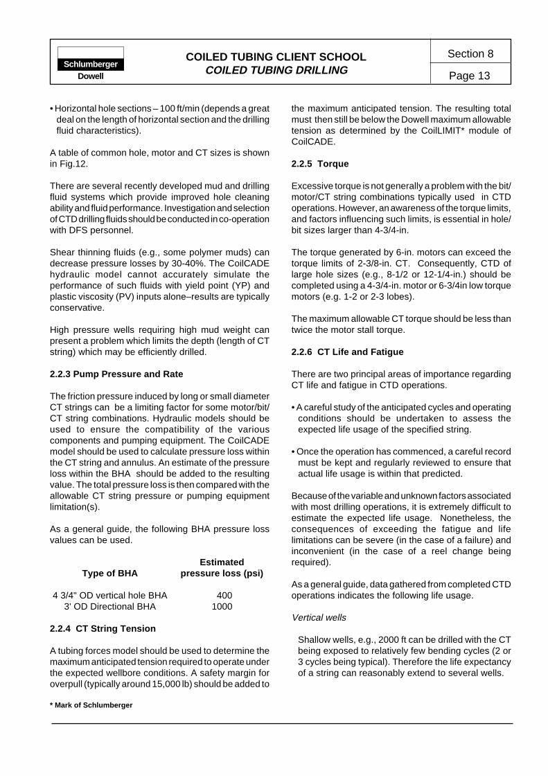
COILED TUBING CLIENT SCHOOLCOILED TUBING DRILLING Page 13
Section 8Schlumberger
Dowell
* Mark of Schlumberger
• Horizontal hole sections – 100 ft/min (depends a greatdeal on the length of horizontal section and the drillingfluid characteristics).
A table of common hole, motor and CT sizes is shownin Fig.12.
There are several recently developed mud and drillingfluid systems which provide improved hole cleaningability and fluid performance. Investigation and selectionof CTD drilling fluids should be conducted in co-operationwith DFS personnel.
Shear thinning fluids (e.g., some polymer muds) candecrease pressure losses by 30-40%. The CoilCADEhydraulic model cannot accurately simulate theperformance of such fluids with yield point (YP) andplastic viscosity (PV) inputs alone–results are typicallyconservative.
High pressure wells requiring high mud weight canpresent a problem which limits the depth (length of CTstring) which may be efficiently drilled.
2.2.3 Pump Pressure and Rate
The friction pressure induced by long or small diameterCT strings can be a limiting factor for some motor/bit/CT string combinations. Hydraulic models should beused to ensure the compatibility of the variouscomponents and pumping equipment. The CoilCADEmodel should be used to calculate pressure loss withinthe CT string and annulus. An estimate of the pressureloss within the BHA should be added to the resultingvalue. The total pressure loss is then compared with theallowable CT string pressure or pumping equipmentlimitation(s).
As a general guide, the following BHA pressure lossvalues can be used.
EstimatedType of BHA pressure loss (psi)
4 3/4" OD vertical hole BHA 4003' OD Directional BHA 1000
2.2.4 CT String Tension
A tubing forces model should be used to determine themaximum anticipated tension required to operate underthe expected wellbore conditions. A safety margin foroverpull (typically around 15,000 lb) should be added to
the maximum anticipated tension. The resulting totalmust then still be below the Dowell maximum allowabletension as determined by the CoilLIMIT* module ofCoilCADE.
2.2.5 Torque
Excessive torque is not generally a problem with the bit/motor/CT string combinations typically used in CTDoperations. However, an awareness of the torque limits,and factors influencing such limits, is essential in hole/bit sizes larger than 4-3/4-in.
The torque generated by 6-in. motors can exceed thetorque limits of 2-3/8-in. CT. Consequently, CTD oflarge hole sizes (e.g., 8-1/2 or 12-1/4-in.) should becompleted using a 4-3/4-in. motor or 6-3/4in low torquemotors (e.g. 1-2 or 2-3 lobes).
The maximum allowable CT torque should be less thantwice the motor stall torque.
2.2.6 CT Life and Fatigue
There are two principal areas of importance regardingCT life and fatigue in CTD operations.
• A careful study of the anticipated cycles and operatingconditions should be undertaken to assess theexpected life usage of the specified string.
• Once the operation has commenced, a careful recordmust be kept and regularly reviewed to ensure thatactual life usage is within that predicted.
Because of the variable and unknown factors associatedwith most drilling operations, it is extremely difficult toestimate the expected life usage. Nonetheless, theconsequences of exceeding the fatigue and lifelimitations can be severe (in the case of a failure) andinconvenient (in the case of a reel change beingrequired).
As a general guide, data gathered from completed CTDoperations indicates the following life usage.
Vertical wells
Shallow wells, e.g., 2000 ft can be drilled with the CTbeing exposed to relatively few bending cycles (2 or3 cycles being typical). Therefore the life expectancyof a string can reasonably extend to several wells.

COILED TUBING CLIENT SCHOOLCOILED TUBING DRILLING
Section 8
Page 14Schlumberger
Dowell
ANNULAR VELOCITY – MOTOR/HOLE SIZE vs. CT SIZE
Flowrate Hole ID Annular Velocity (ft/min)(BPM) (in.) 1-3/4-in CT 2-in.CT 2-3/8-in. CT
2-7/8-in. motor 2.00 3.750 187 205 2442.00 4.125 148 158 1812.00 4.750 106 111 1222.00 6.125 60 61 652.00 7.000 45 46 472.00 8.000 34 34 352.00 9.000 26 27 27
2-3/8-in motor 2.30 3.750 215 235 2812.30 4.125 170 182 2082.30 4.750 121 128 1402.30 6.125 69 71 742.30 7.000 52 53 552.30 8.000 39 39 412.30 9.000 30 31 31
3-1/2-in. motor 2.30 4.125 170 182 2082.30 4.750 121 128 1402.30 6.125 69 71 742.30 7.000 52 53 552.30 8.000 39 39 412.30 9.000 30 31 31
3-1/2-in. motor 2.60 4.125 192 206 2352.60 4.750 137 144 1582.60 6.125 78 80 842.60 7.000 58 59 622.60 8.000 44 45 462.60 9.000 34 35 36
4-3/4-in. motor 4.75 6.125 - 146 1534.75 7.000 - 109 1134.75 8.000 - 81 844.75 9.000 - 64 65
4-3/4-in. motor 6.00 6.125 - - 1946.00 7.000 - - 1426.00 8.000 - - 106
Figure 12. Annular velocities for different hole size/motor/CT string combinations.

COILED TUBING CLIENT SCHOOLCOILED TUBING DRILLING Page 15
Section 8Schlumberger
Dowell
Deviated wells
Data from previous operations indicate that a 2-in. CTstring can, on average, be used for three or four re-entry wells. Similarly, a 2-3/8-in. CT string is typicallyused on two to three wells.
In all cases, continuous monitoring (TIM* and CoilLIFE)is essential to ensure that prescribed limits are notexceeded.
2.2.7 CT Reel Handling
One of the main constraints on the size and length ofCT strings are the limits imposed by road transportweight regulations and offshore crane capacity. Whileit may be undesirable to assemble (field weld) workstrings, it may be the only option in the case of limitedroad weights. Offshore crane capacity restrictions canbe overcome, in some circumstances, by spooling thetubing between a supply boat and platform. Using thistechnique, the empty reel is lifted to the platform andrigged up to spool the tubing string from a shipmentspool on the boat deck.
2.2.8 Directional Requirements
Applications which require directional control andmonitoring require special investigation and theinvolvement of directional engineers at an early stage.As a guide of current capability, the following limitsapply.
• Downhole temperature – currently limited to 310°Fmaximum.
• Deviation build rates – A function of tool string lengthand stiffness with, in general, longer tool stringsrequiring lower build rates. Also, aggressive buildrates can limit the efficiency of orienting tools. Thecurrent orienting tool is designed to operate withindog-legs of up to 30°/100 ft. The Slim 1 tool (with low-flow pulser) can operate in a dog leg severity of 55°/100 ft.
• Hole size – Currently, directional assemblies utilize a2-7/8-in. monel housing. Consequently, the minimumhole size with directional control is 3-1/2-in.
2.3 CTD Project Preparation
The preparation for a CTD project typically involves co-ordinating the input of several specialist disciplines tocompile an overall job plan or procedure. In most casesit is desirable to assign one engineer as the person incharge of the design and preparation of the CTDoperation. Logically, this person will provide a focusedpoint of contact between client and contractor(s), andbe available for operation support duties during theexecution of the CTD project.
The tasks required to be completed in this phase ofCTD project preparation may be summarized astechnical or administrative. Regardless of how thevarious elements are categorized, each should beregarded as a key component which is essential forcompletion of a safe and successful CTD project.
2.3.1 Technical Preparation
There are several tasks to be performed, each withassociated deadlines, in the process of technicalpreparation. The tasks can be planned, and appropriateduties delegated, with the help of check lists in thefollowing principal areas.
• Basic equipment and services
• Procedures and planning
• Drawings and schematic diagrams
• Personnel
To enable the efficient management and co-ordinationof these individual areas, it is advisable to prepare a listof tasks required to complete technical preparation.Such a list should contain information on the task,designated person, deadline and additional informationappropriate to the specific task.
2.3.2 Basic Equipment and Services
To help identify the source(s) of equipment, servicesand expertise necessary to complete the project,comprehensive check lists should be prepared underthe headings shown below.
Each list should be formatted to include an accuratedescription of the item or service, the source andapplicable deadlines or leadtimes.

COILED TUBING CLIENT SCHOOLCOILED TUBING DRILLING
Section 8
Page 16Schlumberger
Dowell
• Surface equipment
• Consumables
• Spare parts and supplies
• Dowhhole tools
• Associated services
2.3.3 Procedures and Plans
Due to the complex nature of the overall operation, it isrecommended that detailed procedures and plans beprepared for the principal project elements. Theseprocedures should take account of the specific wellsite,wellbore and reservoir conditions (or anticipatedconditions) under which they will be executed.
All procedures and plans should be carefully reviewedby the personnel, groups or organisations involved. Insome cases it may be necessary to adopt a formalreview and approval process to ensure all partiesacknowledge acceptance.
Note: Ensure that each document is clearly identifiedwith a date or version number. This will minimiseconfusion and error where several parties are providedwith procedures or plans.
The following list includes typical elements of a CTDproject. This list comprises the basic requirements of anumber of CTD applications, consequently, someelements may not be applicable. Similarly, additionalelements may be required for specific CTD project(s).
• Mob/demob organisation
• Rigging up/down
• Setting whipstock & milling window (if required)
• Well control
• Well control equipment testing
• BHA deployment even overbalance
• Running and setting liner or casing (if required)
• Running completion string
• Cementing job design
• Mud program
• Contingency plans
• Emergency responses (in the event of fire, etc)
2.3.4 Drawings and Schematic Diagrams
Much of the explanation required within proceduresand plans can be simplified by the use of clear andsuitably detailed drawings and schematic diagrams.The following list includes typical examples of drawingsor schematic diagrams for CTD projects.
Note: Ensure that each document is clearly identifiedwith a date or version number. This will minimiseconfusion and error where several parties are providedwith procedures or plans.
• Wellbore schematic (at each stage of the operation)
• Trajectory plot if deviated
• Surface equipment lay out with dimensions (or scale)including indication of restrictive zoning whereapplicable, e.g., Zone II
• BOP stack schematic with heights and dimensions
• BHA schematics (fishing diagram for each assembly)
• High pressure and low pressure lines schematics
• Electrical wiring of surface equipment
2.3.5 Personnel
In addition to the availability and assignment ofpersonnel, there may be several issues which shouldbe addressed. The following examples may apply to theorganisation of CTD personnel for various applicationsand locations.
• Training and certification of personnel
• Personnel job descriptions
• Operations and support organisation organograms
2.3.6 Administrative Preparation
Clarify and finalize arrangements between the clientand third party contractor(s). The final agreement should
COILED TUBING CLIENT SCHOOLCOILED TUBING DRILLING Page 17
Section 8Schlumberger
Dowell
include the following sections:
• Equipment list provided by contractor and operator
• Personnel list provided by contractor
• List of services provided by contractor and operator
• Liability clauses
• Day rates, lump sums, incentives and penalties includingforce majeure
3 EXECUTION
3.1 Well Control (Overbalanced Drilling)
This section addresses only well control in over balanceddrill ing applications. The issues concerningunderbalanced drilling are addressed separately inSection 3.4.
Most conventional well control precautions andprocedures used for conventional drilling apply tooverbalanced CTD (with minor modifications). Forexample, in slim hole wells, it is vital that kicks aredetected as soon as possible. Within the relativelysmall wellbore, even small influxes of reservoir fluid candisplace a significant volume of drilling fluid–resulting ina rapid worsening of the situation. Dynamic kill is not aviable option for CTD due to the small annular pressureloss. The wait and weight method or the driller's method,such as used for kick control on conventional drillingoperations is typically used.
The preferred kick detection system for CTD operationsis to use a flowmeter installed on the return line. Theequipment is described in the surface equipment sectionof this manual.
If foam or air is being used as a drilling fluid, theimplication is that the reservoir pressure is very low. Inthe event of a kick, the well will generally kill itself, orworst case, pumping water will kill the well. Pressuredeployment of the BHA is typically required if drillingwith foam in a gas reservoir. This is necessary as thefoam may break when tripping, resulting in unstablewellbore conditions.
CTD well control procedures and policies are describedin the Dowell safety and loss prevention manual(SLP22) which also refers to the Sedco Forex WellControl handbook.
3.2 Conventional Sidetracking
The term conventional sidetracking or re-entry appliesto CTD operations which are undertaken under thefollowing conditions.
• The well is killed and all subsequent CTD activities areperformed in overbalanced conditions.
• The original completion tubulars have been removed.
• A mechanical whipstock is used to initiate windowmilling operations in the casing or liner.
There are four distinct operational phases in completinga conventional side tracking operation. Each phase willrequire the involvement of different specialist skillswhich may require the participation of third partysuppliers or service companies.
• Well preparation
• Preparing/setting the whipstock
• Milling the window
• Drilling the sidetrack
Conventional sidetracking is currently undertaken atdepths in excess of 10,000 ft, with resulting drain holediameter within a range of 3-1/2- to 6-in (Fig 13).
The application of conventional CTD sidetrackingtechniques have special significance on offshoreplatforms, where mobilization and logistic difficultiesmay render conventional rig-based re-entry techniquesnon-viable. The economic viability of onshore CTD re-entry operations is greatly dependent on the localavailability, and suitability, of conventional rigs andequipment.
3.2.1 Well Preparation
The following list summarizes the operations typicallyrequired as well preparation for setting the whipstockthen continuing with subsequent milling and drillingoperations.
• Kill the well
• Nipple down christmas tree and nipple up well controlequipment
COILED TUBING CLIENT SCHOOLCOILED TUBING DRILLING
Section 8
Page 18Schlumberger
Dowell
• Test the well control equipment
• Pull the production tubing and retrieve packer (ifrequired)
• Squeeze cement off perforated interval (if necessary)or set cement plug and/or set bridge plug• Run CCL(to check for casing collars at the KOD), CBL (to checkcement/bond quality) and Gamma Ray (to correlatedepth).
• Run a casing scrapper to the KOD
3.2.2 Setting the Whipstock
The procedures and equipment necessary to set thewhipstock depends on the operation objectives. Ifazimuth control is required, then a whipstock anchormust be set. The whipstock anchor is necessary toensure the whipstock is correctly orientated, to allowmilling and drilling operations to be started along thecorrect trajectory.
The following list summarizes the activities which maybe necessary to run and set a mechanical whipstockready for milling operations.
• If azimuth control is required, set the whipstockanchor. This is typically run on wireline, but CTconveyance may be appropriate in somecircumstances.
• Perform a gyro survey to determine the orientation ofthe whipstock anchor. The orientation must be knownto allow the whipstock key to be set. Thereby ensuringthe whipstock orientation is correct when set on thewhipstock anchor.
• Prepare the whipstock – if run without an anchor, thewhipstock is equipped with a set of slips which are seton the casing wall (similar to packer slips). A bridgeplug or cement plug must be set at the kick off depthto enable the whipstock slips to be set with set-downweight. If the whipstock is to be used with an anchor,a mule shoe and orientation stinger will be made up tothe bottom of the whipstock.
• Run and set the whipstock
Whipstock run with an anchor and stinger
The BHA is run in the hole, the anchor is tagged andstinger engaged into the anchor. A swivel assembly
allows the stinger to rotate freely allowing correct align-ment of the whipstock and anchor. Weight is thenapplied to set the slips in the anchor, overpull confirmsthat the stinger is anchored. A release stud between thewhipstock and the running tool is then sheared withadditional overpull, and the running assembly is retrievedor milling of the window starts if a starting mill is run withthe running tool.
Whipstock run without an anchor
The BHA is run in the hole, the cement plug or bridgeplug tagged and the whipstock slips set. A shear studon the running tool is sheared by applying weight (or bypulling depending on the type of whipstock). The runningassembly is then retrieved or milling of the windowstarts if a starting mill is run with the running tool.
In some applications a special mill/motor assembly isused as a running tool. The advantage being the abilityto start milling immediately the whipstock is set, with noneed to retrieve and change the BHA (see below).
3.2.3 Window Milling
It is generally recommended that window milling beperformed using low speed motors (typically 3-1/2- or4-3/4-in. motors, depending on hole size). The necessaryweight-on-bit being provided by drill collars. The WOBrequired to mill a casing window does not generallyexceed 1,000 to 2,000 lbf. A representative of thewhipstock vendor or directional drilling company isgenerally required on location to supervise thepreparation and execution of window milling operations.
There are two basic options for window milling using amechanical whipstock.
• Using a conventional starting mill/whipstock lugcombination.
• Using a diamond speed mill
Starting mill/whipstock lug combination
The following list summarizes the activities necessaryto mill a casing window using a starting mill and whipstocklug.
• A conventional starting mill is first made up to a lowspeed motor and run in the hole to mill about 3 ft ofcasing and the whipstock lug.

COILED TUBING CLIENT SCHOOLCOILED TUBING DRILLING Page 19
Section 8Schlumberger
Dowell
Figure 13. Typical conventional sidetrackconfiguration.
Completion tubularsremoved
Top of window
Controlled wellbore conditionsallows appropriate wellheadequipment to be fitted.
Whipstock
Bottom of window
Whipstock packer
• The starting mill is replaced by a window mill and awater melon mill. The water melon mill being made upbetween the window mill and the motor. About 9 ft ofwindow is milled, followed by approximately 5 ft offormation. Drilling the formation allows the next millingassembly to enter the open hole when dressing offthe window.
• A string mill is made up on top of the water melon millfor reaming the window section.
As an alternative to the multiple runs and BHA changesoutlined above, the low-speed motor can be used as awhipstock running assembly. This enables windowmilling to commence immediately after the whipstockshear stud has released, i.e., a BHA change is notnecessary to start milling. A check must be made toensure the motor can withstand the necessary pull orset down weights required to set the whipstock andshear the stud.
Diamond speed mill (no lug in the whipstock concave)
• A diamond speed mill and low speed motor assemblyis used to mill approximately 5 ft of window.
• A water melon mill is then made up above the speedmill to complete the window and to drill approximately5 ft of formation.
• A string mill is then made up above the water melonmill for reaming the window section.
3.3 Thru-Tubing Re-entry
The term thru-tubing reentry applies to CTD operationswhich are undertaken under the following conditions.
• Operations are conducted over (or through) thechristmas tree.
• The original completion tubulars remain in place.
• Well control equipment is used to enable under- orover-balanced drilling to be conducted safely.
Thru-tubing reentries can only be undertaken using milland bit assemblies which are compatible with theminimum ID (restriction) present in the tubing string orcompletion. In some cases, tubing restrictions may bemilled out or cut to allow access for larger mills and bits.Nondirectional deepenings and sidetracks maygenerally be undertaken through completion strings of
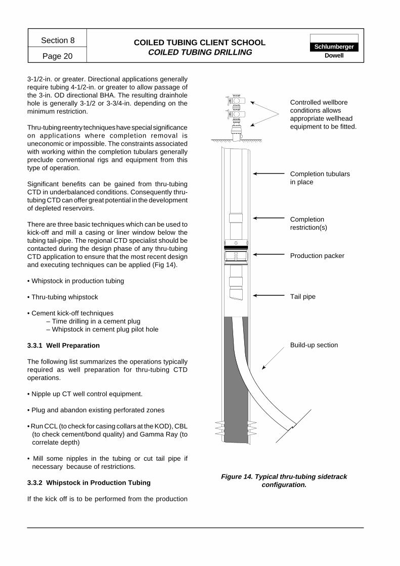
COILED TUBING CLIENT SCHOOLCOILED TUBING DRILLING
Section 8
Page 20Schlumberger
Dowell
Production packer
Completion tubularsin place
Tail pipe
Build-up section
Completionrestriction(s)
Controlled wellboreconditions allowsappropriate wellheadequipment to be fitted.
Figure 14. Typical thru-tubing sidetrackconfiguration.
3-1/2-in. or greater. Directional applications generallyrequire tubing 4-1/2-in. or greater to allow passage ofthe 3-in. OD directional BHA. The resulting drainholehole is generally 3-1/2 or 3-3/4-in. depending on theminimum restriction.
Thru-tubing reentry techniques have special significanceon applications where completion removal isuneconomic or impossible. The constraints associatedwith working within the completion tubulars generallypreclude conventional rigs and equipment from thistype of operation.
Significant benefits can be gained from thru-tubingCTD in underbalanced conditions. Consequently thru-tubing CTD can offer great potential in the developmentof depleted reservoirs.
There are three basic techniques which can be used tokick-off and mill a casing or liner window below thetubing tail-pipe. The regional CTD specialist should becontacted during the design phase of any thru-tubingCTD application to ensure that the most recent designand executing techniques can be applied (Fig 14).
• Whipstock in production tubing
• Thru-tubing whipstock
• Cement kick-off techniques– Time drilling in a cement plug– Whipstock in cement plug pilot hole
3.3.1 Well Preparation
The following list summarizes the operations typicallyrequired as well preparation for thru-tubing CTDoperations.
• Nipple up CT well control equipment.
• Plug and abandon existing perforated zones
• Run CCL (to check for casing collars at the KOD), CBL(to check cement/bond quality) and Gamma Ray (tocorrelate depth)
• Mill some nipples in the tubing or cut tail pipe ifnecessary because of restrictions.
3.3.2 Whipstock in Production Tubing
If the kick off is to be performed from the production
COILED TUBING CLIENT SCHOOLCOILED TUBING DRILLING Page 21
Section 8Schlumberger
Dowell
tubing, a conventional whipstock and anchor can be setin the tubing and a window milled in tubing and thecasing/liner. The hardware and techniques requiredare currently available and are relatively conventional.However, some modifications may be required.
It is generally not possible to set a whipstock in theproduction tubing tail pipe. Therefore, the whipstockwill need to be set above the production packer. This isgenerally an unacceptable option, consequently thistechnique has limited application.
3.3.3 Thru-tubing Whipstock
Thru-tubing whipstocks are a relatively recentdevelopment which requires ongoing refinement toimprove reliability. The size ranges available arecurrently restrictive (through 4-1/2-in. tubing to setinside 7-in, casing or liner). However this will undoubtedlyincrease as the tool reliability improves and thetechniques become more common.
Current (1995) thru-tubing whipstocks can only beused to sidetrack on the high side of the hole. They areavailable from Baker Oil Tools, Weatherford and TIW.As of mid 95, only the BOT thru-tubing whipstock havebeen successfully field tested.
3.3.4 Cement Kick-off Techniques
Both of the cement kick-off techniques outlined beloware recently developed and are undergoing continuedtesting and development.They both require the accurateplacement of a high quality, high compressive-strengthcement plug. Consequently, sufficient effort andresources should be allocated to ensure the successfuldesign and execution of the cement plug placement(Fig 15).
Cement plug preparation
• A cement plug of high compressive-strength is placedin the interval 50 ft below the kick-off depth to thebottom of the tail pipe (subject to length and volumes).After the cement has adequately cured, the top of thecement is tagged and dressed if necessary.
• The cement in the tail pipe is then drilled out using adirectional BHA comprising a diamond speed mill anda slightly bent motor (± 0.25°)
• Once out of the tubing the bend is oriented in thedirection of the desired sidetrack. This is achieved
using the gravity tool face and the hole gyro survey.Drilling is continued through the cement plug, keepingthe tool face until it reaches the kick-off depth (KOD).
Time drilling from a cement plug
• The BHA is retrieved and the bend changed to a higherangle (± 2.5°).
• The window is milled using a time drilling technique,i.e. milling with low WOB (or low motor differentialpressure), running the CT string in short intervals (1/4-in. or 1/2-in. only) with predetermined delay intervals.The delay time will vary throughout the milling operationas the quantity of steel to be cut varies through thewindow.
• When the window and approximately 5 ft of formationhave been drilled, the BHA is retrieved.
• The window is then dressed using a water melon millassembly similar to that outlined in the conventionalsidetracking section. A bull nose (no bit) is made upat the bottom of the water melon mill to avoid drillingout the cement by accident while dressing the window.
Whipstock set in the cement plug pilot hole
• The pilot hole is drilled in the cement plug approximately10 ft deeper than the KOD. This rat hole is used to setthe bottom section of the whipstock.
• The BHA is retrieved and the appropriate whipstock isrun to bottom.
• After carefully tagging bottom, the whipstock assemblyis correctly oriented using an orienting tool. By applyingweight, the slips of the whipstock are set against thecasing/cement. Additional weight parts the shear-stud allowing retrieval of the running assembly.
• A straight milling BHA with a diamond speed mill is runto mill the window and approximately 5 ft of formation.
• The window is then dressed using a water melon millassembly similar to that outlined in the conventionalsidetracking section.
The regional CTD specialist should be consulted duringthe design phase of any thru-tubing CTD application onwhich either of the above cement kick-off techniquesare to be used.

COILED TUBING CLIENT SCHOOLCOILED TUBING DRILLING
Section 8
Page 22Schlumberger
Dowell
Figure 15a. Time-drilled cement kick-off (thru-tubing).
Completioncomponents in place
Cement inside tailpipe
Drillout tailpipe
Hole oriented to casingwall
Hole made to kick-offdepth
Time-drill window cut
Window dressed andbuild-up radius drilled
Figure 15b. Whipstock cement kick-off (thru-tubing).
Cement inside tailpipe
Drillout tailpipe
Hole oriented to casingwall
Hole made to kick-offdepth + requiredrathole for whipstock
Thru-tubing whipstock
Whipstock window cut
Completioncomponents in place

COILED TUBING CLIENT SCHOOLCOILED TUBING DRILLING Page 23
Section 8Schlumberger
Dowell
3.4 Underbalanced Drilling
3.4.1 Definition and Objectives
There has been confusion regarding the definition ofunderbalance drilling. For example, foam/air drilling ordrilling with a parasite string without the well flowing iscalled sometimes underbalanced drilling. However,this is in fact overbalanced drilling if the well does notflow. The term underbalanced drilling implies that thereservoir pressure is at all times higher than theequivalent circulating density of the fluid in the annulus.Under these conditions, the well will be capable offlowing reservoir fluid while drilling or tripping.
The principal objective of underbalanced drilling is toavoid formation impairment caused by the invasion ofdrilling fluid. Some of the horizontal wells drilledunderbalanced by CTD have production ratesapproximately twice that of nearby wells which weredrilled overbalanced. These nearby wells were drilledusing conventional techniques and are completed withlarger wellbore and completion tubulars.
Underbalanced drilling is not a damage free technique.However, the potential increase in well productivityoutweighs most of the associated risks. Permeabilityreduction resulting from the imbibition of drilling fluidcan occur. However, the relative effect is significantlyless than overbalanced drilling damage. The absenceof a protective sealing filter cake can also result in someformation damage when the well is shut in. Furtherinvestigation is necessary to assess the extent of thesedamages for the various types of drilling fluids in differentformation types. An appropriate choice of deploymenttechnique to avoid shutting the well, may be the key tolimiting reservoir damage.
One of the main concerns while drilling underbalancedis maintaining borehole stability. Such concerns areheightened under the following conditions.
• If no liner or casing has been set over the cap rockinterval above the pay zone
• In unconsolidated reservoirs
• In heterogeneous reservoirs with, for example, shalestringers.
Consequently, the reservoir stability and homogeneityneed to be evaluated for all candidate wells. Precautionsto contol or limit borehole instability include:
• Careful controlling the degree of underbalance.
• Selecting appropriate drilling fluids to minimize adversereactions with sensitive formations.
• Setting a casing or liner at the top of the reservoir.
Underbalanced drilling may be likened to drilling whiletaking a kick. However, the equipment and techniquesused are specifically designed to operate under theseconditions, unlike conventional drilling. Also, since thecompletion tubular and christmas tree are still in place,a high level of control can be maintained. Safety issuesare also affected by the reservoir pressure.
Thru-tubing underbalanced drilling is generallyacceptable to regulatory agencies, largely as a result oflong established CT workover procedures andexperience in live wells.
3.4.2 Creating Underbalanced Conditions
Creating and controlling the correct degree ofunderbalance can be an extremely complex process.For example, computer models provide the only practicalmeans of predicting the well head and bottom holepressures in a two phase flow.
The means of creating suitable underbalancedconditions depends greatly on the anticipated reservoirpressure. Reservoir pressure can be characterised asbeing either above or below the hydrostatic pressure ofa column of water in the wellbore.
Reservoir pressure above water column hydrostaticpressure
Under these conditions, underbalanced pressure canbe created by using a fluid(s) which is less dense thanwater. In marginal cases, careful analysis of theequivalent fluid density while circulating solids in theannulus should be conducted to ensure underbalancedconditions exist.
Reservoir pressure below water column hydrostaticpressure
Underbalanced pressure conditions can be created inthree basic ways.
• Use a low density drilling fluid
• Use annular gas-lift
COILED TUBING CLIENT SCHOOLCOILED TUBING DRILLING
Section 8
Page 24Schlumberger
Dowell
production tubing should be performed under live wellconditions to avoid potential damage during shut-in.From a cost and efficiency standpoint, a parasitestring is generally not the best option.
• Gas lift system in the production tubing – if the well isor needs to be equipped with a gas-lift productionstring and the tubing is large enough to achieve thescope of work, then the gas lift assisted drilling can bean economic option. If the well is not suitably equipped,the production string can be pulled and replaced withlarger tubing.
Well kick-off and appropriate fluids
Some marginal wells may quickly load-up and becapable of flowing only in ideal conditions. In suchcases, nitrogen kick-off and careful fluid selection (andcontrol) may be sufficient to support underbalanceddrilling with CT. This method is only applicable in wellswith high GOR.
3.4.3 Controlling Underbalance Pressure
A surface choke is the primary means of controlling thedegree of underbalance created downhole. However, ifgas lift mandrels or a parasite string is used, the gas ornitrogen injection rate will also provide a means ofcontrol. Experience has shown that the surfaceequipment commonly used to treat return fluid, createsa significant back pressure. Consequently, varying thegas lift system parameters to control the degree ofunderbalance is of limited value.
A downhole annulus-pressure sensor helps to accuratelymonitor the bottom hole pressure. This can ensure theunderbalance is maintained over a horizontal wellboresection (assuming the reservoir pressure remainsconstant over the horizontal interval).
3.4.4 Well Pressure Control
Well control procedures used for conventionaloverbalanced drilling are no longer applicable forunderbalanced drilling. A gas or oil kick does notrequire that the well be killed even when tripping.
For a thru-tubing underbalanced operation, with thechristmas tree in place, the well control or safetyprocedures are the same as when performing live wellservice operations, and are well documented.
• Use nitrogen to kick-off the well, then use appropriatefluids
Low density fluids
The following low- and ultra low-density fluids havebeen used for drilling. This method is applicable to mostwells with low or high gas-oil-ratios (GOR).
• Oil based fluids – use is limited to reservoirs withpressure corresponding to an equivalent mud weight(EMW) of at least 7 ppg. Oil based fluids must beconditioned after the well returns have been passedthrough the separators and mud treatment equipment.
• Nitrified or aerated fluid or foam – in wells with a highGOR, nitrified foam or mud is the only solution to avoiddownhole explosion or fire. In wells having a lowGOR, the use of an aerated foam or mud instead ofnitrified systems needs careful risk analyses. Foam istypically the best option since a number of computermodels are available to predict foam performance,pressure losses and resulting EMW. Treatment anddisposal of the wellbore returns are significantproblems encountered with foam based fluid systems.
• Gas – natural gas, air or an inert gas like nitrogen haveall, at some time, been used in drilling operations. Dueto the risk, and consequences, of downhole fires andexplosions, Dowell only recommend nitrogen. A carefulrisk analysis is required for all non-inert gas (or air)applications. Regardless of the gas used, this type ofdrilling is generally performed in very hard formationwith very low permeability (such as found in the RockyMountain region). Such applications are quite distinctfrom "normal" underbalanced drilling with CTD.
Annular gas lift
Two methods are in relatively common use to assistwith drilling operations. Both being applicable in wellswith low GOR.
• Parasite string – the existing production tubing ispulled and a casing or tubing string with a parallelparasite string is set in place. The setting depth isdependent on the formation pressure, i.e., the moredepleted the reservoir, the deeper the string injectionpoint will be.
On concluding the drilling operations, the parasitestring is pulled and a production tubing string run.Ideally, retrieving the parasite string and running the
COILED TUBING CLIENT SCHOOLCOILED TUBING DRILLING Page 25
Section 8Schlumberger
Dowell
For non thru-tubing underbalanced operations, ac-cepted procedures are not well documented and eachapplication must be carefully reviewed on a case bycase basis.
3.4.5 Drilling Fluid
The type of drilling fluid is largely determined by themeans by which the underbalance conditions arecreated. The required functions of a drilling fluid usedin underbalanced drilling are not the same as thatrequired for overbalanced drilling. For example, a drillingfluid for underbalanced operations is not required tofulfill the following functions.
• Balance the formation pressure
• Minimize formation damage (filter cake and water loss).
However, the fluid must fulfill the following basicrequirements.
• Efficiently transport cuttings from the wellbore (slipand annular velocity) – previous experiencedemonstrates that cuttings size in underbalancedconditions are such that slip velocity is very low. Acirculating sub above the motor provides the firstoption to increase flow rates for improved hole cleaning(especially in 9-5/8-in. or larger casing). A mud systemwith the appropriate PV, YP, and gel characteristics ispreferred, especially in non thru-tubing applications.
• Cool and lubricate the bit – generally not a major issue.
• Control corrosion – controlled by additives, notgenerally a major issue.
• Provide sufficient inhibition over shale – may be aconcern if shale stringers are to be drilled, althoughcan be addressed with OBM or mud with appropriateadditives.
If a production tubing gas-lift system is used, and shaleinhibition is not a concern, water is generallyrecommended as a drilling fluid. Water can generallyachieve adequate hole cleaning in 4-1/2-in. tubing andeven 7-in. liner below tail pipe. Disposal is simplifiedsince water can generally be dumped or pumped intothe production line.
3.4.6 Wellbore Returns
The simple solution for handling and disposal of wellborereturns, i.e., drilling fluid, oil, gas, formation water andcuttings, is to route the entire return flow to the productionline. Concerns regarding the routing of solids toproduction facilities are minimal, since the volumes ofcuttings for the small hole sizes drilled are generallytolerated–even at high penetration rates. However, theflow line may create enough back pressure to preventthe well from flowing. If the production facilities cannottreat the returned fluids, it may be necessary to treat thereturns independently, i.e., using three phase separators(see Schlumberger Testing).
The schematic diagram in Fig 20b outlines a typicalprocess for treatment of wellbore returns. Returns arecontrolled by the choke manifold, following which theyare routed to the separator(s) where oil, gas, drillingsolids, and water are separated. Sample catchers (e.g.a tee with valves and screens) can be installeddownstream the choke manifold or returns fluid samplesare recovered and centrifuged to recover cuttings.
The separated gas will be vented or flared dependingon volume and local constraints. The separated oil isgenerally stored in an appropriate tank. The residualwater and solids are routed to a settling tank system,from where the water is disposed or recirculated andthe solids cleaned and dumped (either periodically or atthe end of the project). If water or mud needs to bedumped or treated, the same procedures as for normaldrilling operations can apply.
If some of the fine solids are allowed to recirculate, anincrease in fluid density and pumping pressure canresult. In this likelihood, a centrifuge can be used totreat the mud downstream the separator(s). Cuttingsfrom the centrifuge will be collected in cutting bins andsent for treatment later.
On gas wells, when foam is used, the returns willrequire partial separation to allow the gas to be ventedor flared and the broken foam disposed. On foam-drilled oil wells, the surface equipment may need to beadapted or modified to ensure efficient breaking of thereturns prior to separation.
Recirculating foam fluid is an option but requires aspecific separator built to break the foam (by loweringthe pH). Following separation, the liquid pH is increasedto allow recirculation of the foam liquid phase.

COILED TUBING CLIENT SCHOOLCOILED TUBING DRILLING
Section 8
Page 26Schlumberger
Dowell
3.4.7 BHA Deployment
In underbalanced drilling, the BHA needs to be de-ployed, i.e., run and retrieved under pressure and livewell conditions. There are two basic options, either usean external lunricator eg. wireline lubricator or an inter-nal lubricator eg. deployment against the SSSV.
Lubricator/riser
The deployment procedures are similar to those usedwhen deploying CT service tools. It will generally benecessary to deploy the BHA in more than one sectionwhen using a wire line lubricator. On some offshorelocations, there is sufficient riser length to allow theBHA to be deployed in one section.
Techniques allowing the well to flow while tripping, willminimize formation damage which could result fromshut-in.
SSSV deployment
Deploying against the SSSV results in the well beingshut in and therefore balanced. As discussed in aprevious section, the absence of filter cake can affectthe formation during shut-in. However, further studiesare required to determine the extent and nature of suchdamage.
3.4.8 Installing Completion Tubulars
Installing a liner
The deployment technique limits the type of liner to apredrilled liner (jointed or coiled) with the holes pluggedwith aluminium. The liner float shoe has an aluminiumball to allow the deployment under pressure. Thealuminium plugs or ball are removed by spotting acid(with a CT work string) after running and/or setting theliner. Plugged liner can withstand a maximum differentialpressure of only 2,000 psi.
If a jointed slick liner (without collars) is to be rununderbalanced, the injector head can be used to snubthe liner into the well. The length of liner being run willbe limited by the CT and injector head maximum pullcapacities.
If a conventional jointed liner with external collars is tobe run, it will be deployed with a wireline lubricator andthe capacity of the wire line will limit the weight andtherefore the length of the liner.
Coiled tubing liners are run as normal CT using theappropriate size of coiled tubing and well controlequipment.
Installing a production string
A production string will only be required on CTDoperations not performed through the production tubing.Either a CT completion string is run and the CT unitused to run it under pressure or a conventional jointedtubing production string is run by a snubbing unit.
The maximum CT completion size is currently 3-1/2-in.Transportation and handling of 3-1/2-in. CT strings canbe logistically difficult offshore and onshore. It is likelythat the majority of CT completion strings will be limitedto 2-7/8-in. or 2-3/8-in.
3.5 Running and Pulling Wellbore Tubulars
It may be necessary to pull the completion string on re-entry wells before sidetracking or deepening. In addition,the completion may be removed to allow access for aliner to cover and protect the build up section. On newwells, it may be necessary to run one or two strings ofcasing. Two options are available, crane or jackingsubstructure. Selection depends on the weight of thetubulars to be run or pulled.
Crane
Providing the weight of the tubing or casing string doesnot exceed the crane capacity, this is the simplestmethod of running or retrieving the string. However, ifthe string gets stuck, there is limited pulling capacity inreserve.
Conventional drilling slips, elevators, and safety clampsare used. Single joints are handled with the crane whichalso holds the entire tubing or casing string in much thesame way as a rig does. A power tong is required tomake up the connections.
The liner or casing string can be run and made up,floating i.e. partially empty to limit its hanging weight.To run a liner we need to consider the weight of the totalweight of the string (comprising the liner string, linerhanger, running tool, and drill collars to provide weightto push the liner around the build up if it is a directionalwell).
A conventional CT logging deployment technique isused to make up the connection between the stripper

COILED TUBING CLIENT SCHOOLCOILED TUBING DRILLING Page 27
Section 8Schlumberger
Dowell
and the well head after the CT connector has beenconnected to the liner string i.e. the liner string is hungoff in the BOP rams and the CT connector is made upto the liner. The skate pressure is released to allow theinjector head to be stripped over the CT until the BOP/stripper connection can be made up. Once all connec-tions are made up and tested, the string weight is pickedup and the liner released from the BOP ready to RIH.Substructure with jacking system
Dowell has designed and built three different types ofjacking systems to run or pull wellbore tubulars withoutthe requirement for a mast. Both systems include asubstructure and a set of snubbing jacks. The jacksoperate only with downward loading, i.e., they do nothave any snubbing capability.
The Hydra-Rig or Kremco systems have two jacks witha 160,000 lbf pull capacity and an 11 ft stroke. TheHydra Rig system can only be used with 7-1/16-in. orsmaller BOPs.
The third system built by Dreco has four jacks with a200,000 lbs pull capacity and an 8 ft stroke. The systemcan be used with an 13 5/8-in. BOP stack and is the bestsuited system for drilling aplications.
These substructures accommodate a tubing powertong to make up or break the tubing connections. Singlejoints of tubing are handled by the CTU crane. Bothsystems also allow the injector head to be skidded offthe well when running or retrieving the BHA.
4 SURFACE EQUIPMENT
The type of application, location and complexity of theoperation will determine which items of surfaceequipment are specified and then selected. The principalcomponents required to complete most CTD projectscan be categorized as follows.
• CTD substructure or rig
• CT equipment
• Well control equipment
• Pumping equipment
• Mud storage and treatment equipment
• Pipe handling equipment
• Ancillary surface equipment
• Monitoring and recording equipment
• Safety and emergency equipment
• Rig camp and wellsite facilities
4.1 Rigs and Structures for CTD
Coiled tubing drilling is performed with the support ofconventional rotary rig masts and substructures, andwith specially designed substructures and jackingsystems developed for CTD. For obvious reasons,substructures designed specifically for CTD offer thegreatest potential for efficient CTD operations.
4.1.1 CTD Substructures and Jack Systems
On specialized CTD rigs, the functions of the draw-works, crown block, travelling block and drilling line arereplaced by the injector head and jacking system . Therotary table function being replaced by a downholemotor.
4.1.2 Location Requirements
New wells
The location is typically required to be as small aspossible, currently 25m x 32m (Fig. 16) is the minimumfoot print of a CTD rig. A conductor pipe must be drivenprior to the rig mobilization. A small cellar around theconductor will help collect mud and water spills whentripping.
The wellsite requires minimal preparation, basic gradingand levelling generally being sufficient. Provision forguy cable anchor points may be required (dependingon the configuration of the selected equipment).
Re-entry wells
The location has already been established and isgenerally larger than is required.
Offshore wells
The selection and placement of CTD equipment isconstrained by the space and handling capability of therig (semi) or platform. Tender assisted operations cansimplify equipment placement. Basic considerationsfor offshore location planning include the following:
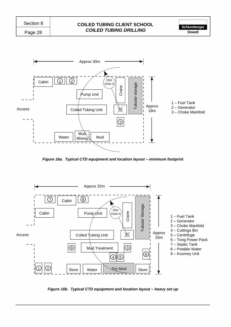
COILED TUBING CLIENT SCHOOLCOILED TUBING DRILLING
Section 8
Page 28Schlumberger
Dowell
1 – Fuel Tank2 – Generator3 – Choke Manifold
Figure 16a. Typical CTD equipment and location layout – minimum footprint
Figure 16b. Typical CTD equipment and location layout – heavy set up
1 – Fuel Tank2 – Generator3 – Choke Manifold4 – Cuttings Bin5 – Centrifuge6 – Tong Power Pack7 – Septic Tank8 – Potable Water9 – Koomey Unit
1 2Cabin
Coiled Tubing Unit
Pump Unit Cra
ne
Tub
ular
sto
rage
Water Mud
3
MudMixing
Access
Approx 30m
Approx18m
15mZone II
1 2
4 56
7 8
9 3
Store StoreDry MudWater
Cabin
Coiled Tubing Unit
Pump Unit
Cra
ne
Tub
ular
Sto
rage
Mud Treatment
Cabin
Access
Approx 32m
Approx25m
15mZone II
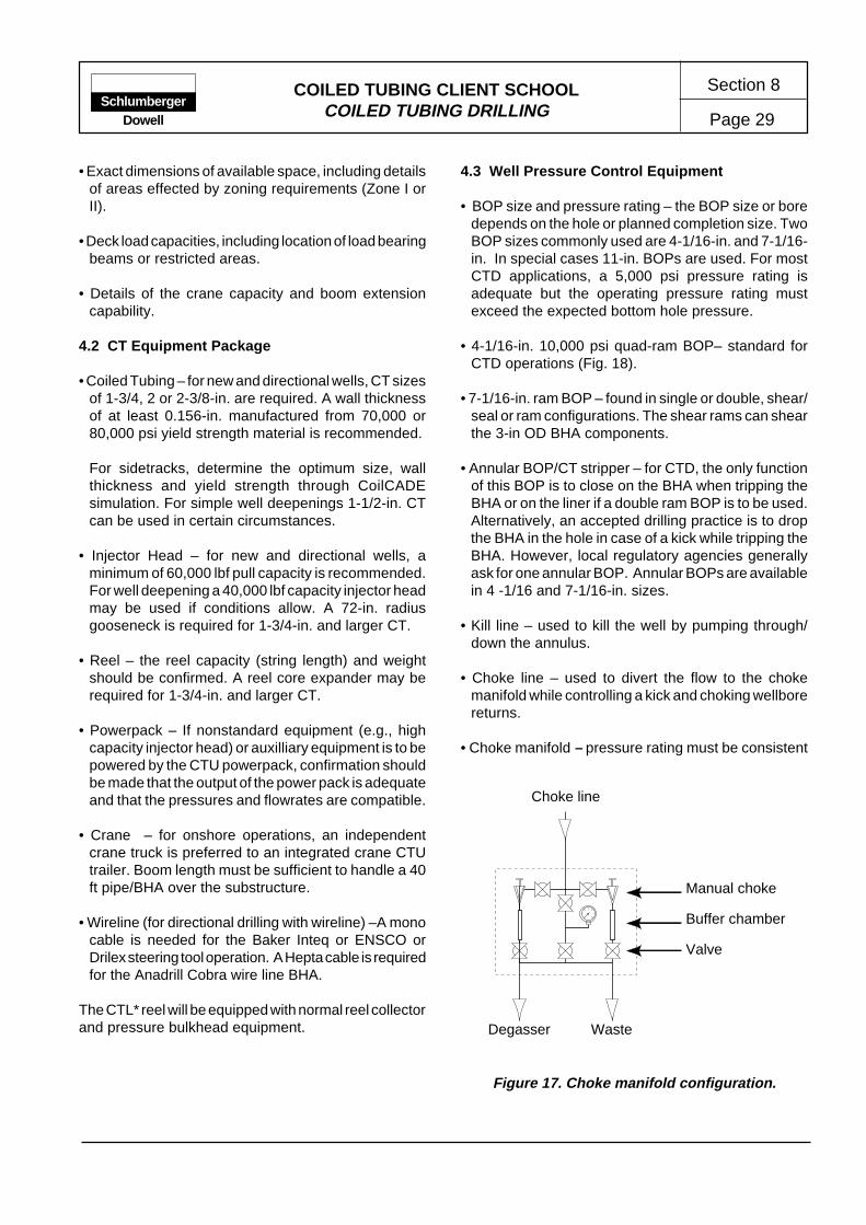
COILED TUBING CLIENT SCHOOLCOILED TUBING DRILLING Page 29
Section 8Schlumberger
Dowell
• Exact dimensions of available space, including detailsof areas effected by zoning requirements (Zone I orII).
• Deck load capacities, including location of load bearingbeams or restricted areas.
• Details of the crane capacity and boom extensioncapability.
4.2 CT Equipment Package
• Coiled Tubing – for new and directional wells, CT sizesof 1-3/4, 2 or 2-3/8-in. are required. A wall thicknessof at least 0.156-in. manufactured from 70,000 or80,000 psi yield strength material is recommended.
For sidetracks, determine the optimum size, wallthickness and yield strength through CoilCADEsimulation. For simple well deepenings 1-1/2-in. CTcan be used in certain circumstances.
• Injector Head – for new and directional wells, aminimum of 60,000 lbf pull capacity is recommended.For well deepening a 40,000 lbf capacity injector headmay be used if conditions allow. A 72-in. radiusgooseneck is required for 1-3/4-in. and larger CT.
• Reel – the reel capacity (string length) and weightshould be confirmed. A reel core expander may berequired for 1-3/4-in. and larger CT.
• Powerpack – If nonstandard equipment (e.g., highcapacity injector head) or auxilliary equipment is to bepowered by the CTU powerpack, confirmation shouldbe made that the output of the power pack is adequateand that the pressures and flowrates are compatible.
• Crane – for onshore operations, an independentcrane truck is preferred to an integrated crane CTUtrailer. Boom length must be sufficient to handle a 40ft pipe/BHA over the substructure.
• Wireline (for directional drilling with wireline) –A monocable is needed for the Baker Inteq or ENSCO orDrilex steering tool operation. A Hepta cable is requiredfor the Anadrill Cobra wire line BHA.
The CTL* reel will be equipped with normal reel collectorand pressure bulkhead equipment.
4.3 Well Pressure Control Equipment
• BOP size and pressure rating – the BOP size or boredepends on the hole or planned completion size. TwoBOP sizes commonly used are 4-1/16-in. and 7-1/16-in. In special cases 11-in. BOPs are used. For mostCTD applications, a 5,000 psi pressure rating isadequate but the operating pressure rating mustexceed the expected bottom hole pressure.
• 4-1/16-in. 10,000 psi quad-ram BOP– standard forCTD operations (Fig. 18).
• 7-1/16-in. ram BOP – found in single or double, shear/seal or ram configurations. The shear rams can shearthe 3-in OD BHA components.
• Annular BOP/CT stripper – for CTD, the only functionof this BOP is to close on the BHA when tripping theBHA or on the liner if a double ram BOP is to be used.Alternatively, an accepted drilling practice is to dropthe BHA in the hole in case of a kick while tripping theBHA. However, local regulatory agencies generallyask for one annular BOP. Annular BOPs are availablein 4 -1/16 and 7-1/16-in. sizes.
• Kill line – used to kill the well by pumping through/down the annulus.
• Choke line – used to divert the flow to the chokemanifold while controlling a kick and choking wellborereturns.
• Choke manifold – pressure rating must be consistent
Figure 17. Choke manifold configuration.
Choke line
Degasser Waste
Manual choke
Buffer chamber
Valve

COILED TUBING CLIENT SCHOOLCOILED TUBING DRILLING
Section 8
Page 30Schlumberger
Dowell
Figure 18a. Typical well control equipment configurations – for hole sizes up to 4-in.
Choke linewithmanualand remotevalve fitted
Deck/floor levelStripper
4-1/16-in. Quad BOP
Mud cross
Casing spool
Mud cross with manualvalve fitted
Kill line to mud pump
Deck/floor levelStripper
Mud cross with manualvalve fitted
Annular BOP
4-1/16-in. Quad BOP
Mud cross
Kill line to mud pump
Choke linewithmanualand remotevalve fitted
Casing spool
Up to 4-in. hole sizewith annular BOP
Up to 4-in. hole sizewithout annular BOP

COILED TUBING CLIENT SCHOOLCOILED TUBING DRILLING Page 31
Section 8Schlumberger
Dowell
Stripper
4-1/16-in. Quad BOP
Mud cross with manualand remote valve fitted
Deck/floor level
7-1/16-in. Annular BOP
7-1/16-in. Shear/seal BOP
Casing spool
Stripper
Mud cross with manualvalve fitted
7-1/16-in. Annular BOP
7-1/16-in. Shear/seal BOP
Casing spool
7-1/16-in. Pipe/slip BOP
Deck/floor level
Figure 18b. Typical well control equipment configurations – for hole sizes 4-1/16-in. to 6 3/4".
4-1/16-in. hole size andgreater with annular BOP
and shear/seal
4-1/16-in. hole size andgreater with annularBOP, shear/seal and
pipe/slip rams

COILED TUBING CLIENT SCHOOLCOILED TUBING DRILLING
Section 8
Page 32Schlumberger
Dowell
* Mark of Schlumberger
with the BOP rating. The manifold must be a drillingtype choke manifold with two manual chokes and onepressure gauge (some applications may require aremote operated choke). This equipment is asimportant as the BOP for the rig safety (Fig 17).
• Mud return line – normally not part of the well controlequipment but when using two BOP stacks, the mudreturn must be closed if it is necessary to shut in thewell. This is achieved with a remote operated valveinstalled on the outlet of the mud return mud cross.
• BOP controls and instruments – the stripper and BOPare controlled from the CT unit control cabin.
For the 7-1/16-in. BOPs and the remote operatedvalves on the mud return or choke lines, the controlposition is located on the accumulator or Koomey unitthat must be positioned next to the CTU cabin. Remotecontrols between the Koomey unit and the CTU BOPcommand panel can be adapted if necessary.
4.4 Kick Detection Equipment
When drilling overbalanced, rapid detection of kicks orlosses is essential in slimhole drilling applications.There are two common methods used in kick detectionsystems. Both have advantages and disadvantageswhen used in CTD operations.
• Flow comparison (flow in vs. flow out)
• Mud tank level monitoring
4.4.1 Flow Comparison
One of the best ways of detecting a flow variation, is tohave a flow meter on the pump suction and one on thewellbore return line. The flow difference (∆ flow) ismonitored and recorded versus time. A ∆ flow increaseindicates a kick, while losses are indicated by a drop in∆ flow.
A mud-pump stroke counter and a flow meter fitted onthe mud return line can also provide adequate data forflow comparison. The outputs of both devices plottedversus time can give a reasonable indication. However,an assumption of constant pump efficiency must bemade. A variety of flowmeters are available for thisapplication. A low-pressure electro-magnetic flow me-ter like the Dowell Mag Flow can be used on the returnline.
4.4.2 Mud Tank Level Monitoring
While in principal this system is simple, it is only efficientif the tank section is small enough to enable a smallvolume variation to be detected. An accurate monitoringand recording system is needed to provide a suitabledisplay. A general trend versus time display format isrequired, a digital display is not sufficient. The MartinDecker-Totco sensor system is currently recommended.
4.5 Mud Sytem
4.5.1 Mud Tanks
There are three types, or functions, of mud tank, i.e.,settling, active and reserve. Additional tankage orstorage facilities may be required for water (Fig 19).
Settling tank
This is the first tank through which the wellbore returnspass. The shale shakers (where fitted) willl normally belocated above this tank. An overflow system from thesettling tank passes to the the active tank. The settlingtank volume is typically 10 to 15 BBL for 2 to 3 bbl/mnflow rates. A large (butterfly) valve is generally fitted tothe base of the tank to allow easy removal of theaccumulated solids.
Active tank
The active,or suction, tank stores the drilling fluid andsupplies the mud pump suction. If continuous treatmentor additive is required it may be added to this tank. Thetank volume is generally around 50 BBL for 2 to 3 bbl/mnflow rates. This allows a mud volume buffer to helpstabilize the mud characteristics. Smaller volume activetanks may be used, however, key fluid parameters suchas viscosity and density can vary quickly if the mudvolume is small.
The active tank suction is manifolded to allow recirculationand precharging of the high-pressure pump. In additionto the recirculation line, a tank agitator is required tomaintain the homogenity of the fluid.
Reserve tank
The reserve tank(s) are used to store a reserve of drillingfluid and also provide a facility for mud treatment orpreparation. Ideally, the reserve mud volume should beequal to the hole volume plus the active and settling tankvolumes. However, this may be reduced if the well type

COILED TUBING CLIENT SCHOOLCOILED TUBING DRILLING Page 33
Section 8Schlumberger
Dowell
Figure 19b. Typical configuration of drilling-fluid equipment – underbalanced operations.
Active
Reserve
Water
Centrifuge
Chokemanifold
MixingHopper
CentrifugalPump
CentrifugalPump
TriplexPump
Wellbore returns
Three phaseseparator
Vacuumdegasser
Gas to flare orproduction
Oil to productionor storage
Active
Reserve
Water
Centrifuge
Shale shaker
SettlingTank
MixingHopper
CentrifugalPump
CentrifugalPump
TriplexPump
Solidssampling
and disposal
Wellbore returns
Figure 19a. Typical configuration of drilling-fluid equipment – overbalanced operations.

COILED TUBING CLIENT SCHOOLCOILED TUBING DRILLING
Section 8
Page 34Schlumberger
Dowell
(exploration or development), downhole pressure orrisk of losses allow. Approximately half to one third ofthis volume can be provided in re-entry of depletedreservoir wells. Similar to the active tank, the reservetank should be fitted with a recirculation and agitationsystem to allow conditioning of the mud.
4.5.2 Mud Treatment Equipment
Shale shaker
A shale shaker is necessary for exploration wells to getrid of the large cuttings produced in the top hole sectionand to collect cuttings for geological analyses.
CTD operations on re-entry wells often do not requireshale shakers because of the very small cuttingsgenerated by the high-speed bit/motor combinations.Short well deepenings, can generally be performedwithout a shaker.
Centrifuge
The centrifuge is an essential item for most CTDapplications except short well deepening and shallownew wells. The centrifuge removes very fine cuttingsand avoids their recirculation, which would in timeincrease the drilling fluid density. Any uncontrolledvariation in fluid density and solids content can increasethe risk of sticking or wellbore instability.
Gas Separation System
Two types of mud degassing equipment is commonlyused (similar to conventional drilling operations).
• Poor boy degaser – located on the mud return line, itknocks out gas using a system of baffles. The resultinggas is vented from a stack designed to route gas awayfrom work areas.
• Vacuum degaser – creates a partial vacuum in aclosed tank to knock out remaining gas. This systemrequires an additional centrifugal pump. Generallythe two systems are combined for maximum efficiency.
Three phase separators
On underbalanced CTD operations, the mud returnsare directed to the choke manifold then to a conventionalthree-phase production separator. The separated gas,oil and solids are then routed to disposal, production orstorage facilities. The gas is either flared or sent to the
production line. The oil is either sent to the productionline or stored for later hauling. The residual solids areremoved either periodically or upon completion of theproject.
4.6 Pumping Equipment
4.6.1 Low Pressure Pumping Equipment
Low-pressure pumping equipment is necessary fortransferring, mixing and conditioning the drilling fluid. Inaddition, the high-pressure pumping equipment requireslow-pressure charge pumps to operate efficiently. Anadequate pre-charge system is especially important ifkick monitoring equipment is relient on the pump strokecounter for fluid inflow data.
A low-pressure manifold system is typically used withtwo low-pressure pumps to enable flexibility andredundancy (Fig. 19). The fluid mixing system typicallycomprises a hopper and jet mixing system supplied byfluid from a centrifugal pump.
4.6.2 High Pressure Pumping Equipment
The high-pressure pump specifications depend largelyon the hole depth and diameter. For holes smaller than4-3/4-in., it is unlikely the pressure will exceed 5,000 psiand a flowrate of 2.5 BPM. For larger holes, typicallyvertical exploration wells, the flow rate may be up to 6BPM. Some redundancy in pumping equipment andcapacity is generally required.
A high-pressure pump remote control panel is generallyinstalled in the CTU cabin. This is necessary to alter orstop the pump flowrate for tool operation or orientation.In addition, close control of the CTU and pumpingequipment is necessary if the downhole motor stalls.
High-pressure piping and manifolding is generallyassembled from 2-in. treating line, chicksans and thenecessary valves and accessories.
4.7 Monitoring & Recording Equipment
• Conventional CTU monitoring equipment – requiredto record the string cycle and pressure data foranalysis with CoilLIFE. A TIM* device should also beregarded as critical monitoring equipment.
• Other monitoring recording systems like the PC basedPrism 2 and 3 software provide real time acquisition,recording and display of the data from a variety of
COILED TUBING CLIENT SCHOOLCOILED TUBING DRILLING Page 35
Section 8Schlumberger
Dowell
sensors. It provides the CT operator with digital dis-play or plots versus time through bar charts or stripcharts on a monitor in the CTU cabin and also allowdata analysis in the CTU or in an office. It makes theCTD job safer (kick detection) and drilling more effi-cient (all parameters displayed versus time, show tothe CT operator the trends, rate of penetration etc).
4.8 Pipe Handling Equipment
This pipe handling equipment is used for handlingjointed pipes e.g. drill collars, tubing joints, casing jointsetc.
• Tubing spider slips – used to hold the BHA or jointedtubing when making up or breaking two joints.
• Elevators – used to handle single joints of DC ortubing or casing.
• Safety clamps – used as a safety device to prevent thestring from falling into the hole, if the slips do not holdand the string slides.
• Tubing power tong – used to make up or break theBHA, casing or tubing connections at the propertorque.
• Crane – used to handle single joints of BHA, casing ortubing. If necessary, it may be used to handle/run thewhole BHA or casing string if within the crane capacity.
• Substructure and jacking system – used to pull or runa whole casing or tubing string. Has a 170,000 lbspulling capacity–single joints are still handled by thecrane.
4.9 Ancillary Surface Equipment
• Substructure – used as a drill floor when tripping theBHA and as a support for the injector head whendrilling or tripping the CT.
• Generator – provides electricity to the portacabins, theflood lights, the centrifuge, the monitoring equipment,the koomey unit etc.
• Electrical distribution panel – provides electricalconnection between the generator and the variouselectrical devices with all necessary breakers andsafety features.
• Flood lights – to provide lights for safe and efficientoperations at night.
• Air compressor – provide air to start the CTU engineif the tractor is not on location, or provide compressedair as needed.
• Miscellaneous – cutting torch and welding machine:
4.10 Safety and Emergency Equipment
• Emergency kill – emergency kill on the CTU engineand pump engines.
• Fire fighting equipment – CO2 fire extinguishers on
CTU power pack, pumping unit power pack, near theportacabins, near the fuel tank.
• H2S protective equipment and gas detectionequipment– generally provided by the operator.
• Eye wash station – located next to the mixing facilitywith a precharged tank filled up with treated water.
• Mud handling protective equipment – apron, goggles,long sleeve gloves for chemical handling.
• First aid kits.
4.11 Equipment and Consumables Chcklists
The checklists shown in Fig. 20 through Fig 21 areintended as a guide for the compilation of checklists forspecific operations.
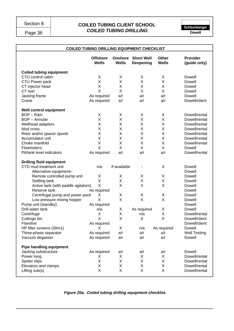
COILED TUBING CLIENT SCHOOLCOILED TUBING DRILLING
Section 8
Page 36Schlumberger
Dowell
COILED TUBING DRILLING EQUIPMENT CHECKLIST
Offshore Onshore Short Well Other ProviderWells Wells Deepening Wells (guide only)
Coiled tubing equipmentCTU control cabin X X X X DowellCTU Power pack X X X X DowellCT injector head X X X X DowellCT reel X X X X DowellJacking frame As required a/r a/r a/r DowellCrane As required a/r a/r a/r Dowell/client
Well control equipmentBOP – Ram X X X X Dowell/rentalBOP – Annular X X X X Dowell/rentalWellhead adapters X X X X Dowell/rentalMud cross X X X X Dowell/rentalRiser and/or spacer spools X X X X Dowell/rentalAccumulator unit X X X X Dowell/rentalChoke manifold X X X X Dowell/rentalFlowmeters X X X X DowellPit/tank level indicators As required a/r a/r a/r Dowell/rental
Drilling fluid equipmentCTD mud treatment unit n/a If available - X Dowell
Alternative equipment– DowellRemote controlled pump unit X X X X DowellSettling tank X X X X DowellActive tank (with paddle agitators) X X X X DowellReserve tank As required DowellCentrifugal pump and power pack X X X X DowellLow pressure mixing hopper X X X X Dowell
Pump unit (standby) As required DowellDrill water tank n/a X As required X DowellCentrifuge X X n/a X Dowell/rentalCuttings bin X X X X Dowell/clientFlareline As required Dowell/clientHP filter screens (Slim1) X X n/a As required DowellThree-phase separator As required a/r a/r a/r Well TestingVacuum degasser As required a/r a/r a/r Dowell
Pipe handling equipmentJacking substructure As required a/r a/r a/r DowellPower tong X X X X Dowell/rentalSpider slips X X X X Dowell/rentalElevators and clamps X X X X Dowell/rentalLifting sub(s) X X X X Dowell/rental
Figure 20a. Coiled tubing drilling equipment checklist.

COILED TUBING CLIENT SCHOOLCOILED TUBING DRILLING Page 37
Section 8Schlumberger
Dowell
COILED TUBING DRILLING EQUIPMENT CHECKLIST (continued)
Offshore Onshore Short Well Other ProviderWells Wells Deepening Wells (guide only)
Ancillary surface equipmentSubstructure (if jacks not used) As required X X X DowellFuel tank and pump n/a As required - - DowellGenerator As required a/r a/r a/r DowellElectrical distribution panel X X a/r a/r DowellCabin(s) (furnished) X X a/r -a/r DowellPotable water tank As required X a/r a/r DowellLighting As required a/r a/r a/r DowellAir compressor As required a/r a/r a/r DowellSteam cleaner X X a/r a/r DowellLocation mats - As required a/r a/r Client
Monitoring and recording equipmentTotco monitoring system X X X X DowellDowell PAQ* X X X X DowellMulti channel recorder X X X X DowellFlowmeters X X X X DowellPACR* X X X X DowellTIM* device X X X X Dowell
Safety equipmentEmergency engine kill X X X X DowellH2S safety equipment As required a/r X X DowellGas detection/monitoring equipment X X X X DowellFire extinguishers X X X X DowellSewage system (cabins) n/a As required - - DowellEye wash station(s) X X X X Dowell
Casing/liner running equipmentElevators and clamps As required a/r DowellCasing or liner joints As required a/r ClientCasing shoe or float As required a/r ClientLiner hanger As required a/r ClientRunning/setting tool(s) As required a/r DowellDrill collars As required a/r Dowell/rentalDrop ball sub a/r Eastman
Figure 20b. Coiled tubing drilling equipment checklist.

COILED TUBING CLIENT SCHOOLCOILED TUBING DRILLING
Section 8
Page 38Schlumberger
Dowell
COILED TUBING DRILLING CONSUMABLES AND MISCELLANEOUS SERVICES CHECKLIST
Vertical Short Well Sidetrack ProviderWell Deepening Well (guide only)
Equipment spares and consumablesPump parts X X X DowellShaker screens X X X DowellMud unit sparts X X X DowellCTU parts X X X DowellWell control equipment parts X X X DowellFuel, oils and lubricants X X X Dowell
Drilling consumables
Drill water X X X ClientPotable water As required a/r a/r ClientDiesel ClientMud products Dowell/clientLCM As required a/r a/r Dowell/clientCement (and additives) As required a/r a/r DowellBits X X X Dowell/clientCore bits As required a/r a/r Dowell/client
Logistics
Vehicles for crew Onshore only DowellHelicopter or crew boat Offshore only ClientConsumables haulage X X X ClientVacuum truck Onshore only ClientCuttings disposal X X X ClientRadio communications As required Client
Sidetracking equipment
Whipstock - - As required Dowell/VendorWhipstock anchor - - As required Dowell/VendorSetting tool (s) - - As required Dowell/VendorGyro/survey equipment - - As required Dowell/VendorMill(s) - - As required Dowell/VendorLow-speed motor - - As required Dowell/Vendor
Logging tools and service
CCL (for sidetrack KOP) SchlumbergerCBL (for sidetrack KOP) SchlumbergerOther services as required Schlumberger
Figure 21. Coiled tubing drilling consumables and miscellaneous services checklist.
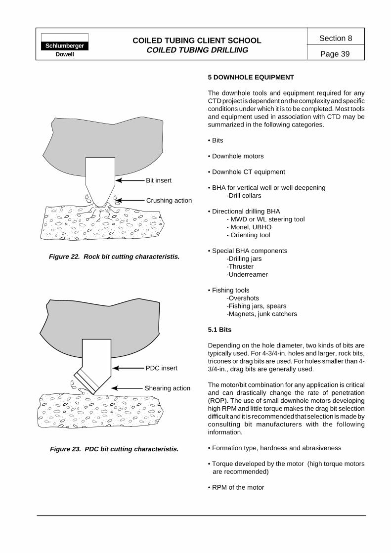
COILED TUBING CLIENT SCHOOLCOILED TUBING DRILLING Page 39
Section 8Schlumberger
Dowell
5 DOWNHOLE EQUIPMENT
The downhole tools and equipment required for anyCTD project is dependent on the complexity and specificconditions under which it is to be completed. Most toolsand equipment used in association with CTD may besummarized in the following categories.
• Bits
• Downhole motors
• Downhole CT equipment
• BHA for vertical well or well deepening-Drill collars
• Directional drilling BHA- MWD or WL steering tool- Monel, UBHO- Orienting tool
• Special BHA components-Drilling jars-Thruster-Underreamer
• Fishing tools-Overshots-Fishing jars, spears-Magnets, junk catchers
5.1 Bits
Depending on the hole diameter, two kinds of bits aretypically used. For 4-3/4-in. holes and larger, rock bits,tricones or drag bits are used. For holes smaller than 4-3/4-in., drag bits are generally used.
The motor/bit combination for any application is criticaland can drastically change the rate of penetration(ROP). The use of small downhole motors developinghigh RPM and little torque makes the drag bit selectiondifficult and it is recommended that selection is made byconsulting bit manufacturers with the followinginformation.
• Formation type, hardness and abrasiveness
• Torque developed by the motor (high torque motorsare recommended)
• RPM of the motor
Bit insert
Crushing action
������������������
���������������������
PDC insert
Shearing action
Figure 22. Rock bit cutting characteristis.
Figure 23. PDC bit cutting characteristis.
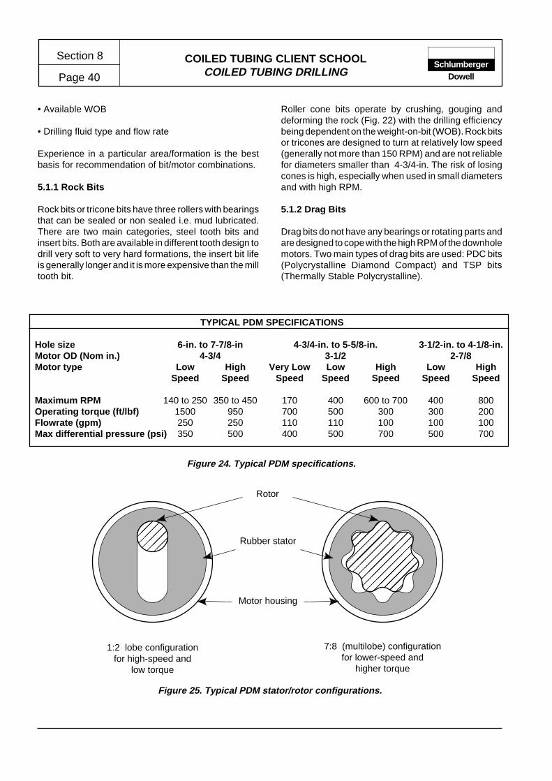
COILED TUBING CLIENT SCHOOLCOILED TUBING DRILLING
Section 8
Page 40Schlumberger
Dowell
• Available WOB
• Drilling fluid type and flow rate
Experience in a particular area/formation is the bestbasis for recommendation of bit/motor combinations.
5.1.1 Rock Bits
Rock bits or tricone bits have three rollers with bearingsthat can be sealed or non sealed i.e. mud lubricated.There are two main categories, steel tooth bits andinsert bits. Both are available in different tooth design todrill very soft to very hard formations, the insert bit lifeis generally longer and it is more expensive than the milltooth bit.
Rubber stator
Rotor
��
������
����
���
����
�����
�����
��
7:8 (multilobe) configurationfor lower-speed and
higher torque
1:2 lobe configurationfor high-speed and
low torque
Motor housing
TYPICAL PDM SPECIFICATIONS
Hole size 6-in. to 7-7/8-in 4-3/4-in. to 5-5/8-in. 3-1/2-in. to 4-1/8-in.Motor OD (Nom in.) 4-3/4 3-1/2 2-7/8Motor type Low High Very Low Low High Low High
Speed Speed Speed Speed Speed Speed Speed
Maximum RPM 140 to 250 350 to 450 170 400 600 to 700 400 800Operating torque (ft/lbf) 1500 950 700 500 300 300 200Flowrate (gpm) 250 250 110 110 100 100 100Max differential pressure (psi) 350 500 400 500 700 500 700
Figure 24. Typical PDM specifications.
Figure 25. Typical PDM stator/rotor configurations.
Roller cone bits operate by crushing, gouging anddeforming the rock (Fig. 22) with the drilling efficiencybeing dependent on the weight-on-bit (WOB). Rock bitsor tricones are designed to turn at relatively low speed(generally not more than 150 RPM) and are not reliablefor diameters smaller than 4-3/4-in. The risk of losingcones is high, especially when used in small diametersand with high RPM.
5.1.2 Drag Bits
Drag bits do not have any bearings or rotating parts andare designed to cope with the high RPM of the downholemotors. Two main types of drag bits are used: PDC bits(Polycrystalline Diamond Compact) and TSP bits(Thermally Stable Polycrystalline).

COILED TUBING CLIENT SCHOOLCOILED TUBING DRILLING Page 41
Section 8Schlumberger
Dowell
PDC bits operate by shearing rock material much likethe action of a machinists tool on a lathe. TSP bits havea similar cutting action, but are more tolerant of heat soare suitable for harder formations. However, the TSPbit cutting surface is significantly smaller than the PDCcutter, consequently penetration rates are typicallyless. In general, drag bits operate more efficiently withless WOB than roller cone bits but are more sensitive torate of rotation.
Some drag bits, and all rock bits, are equipped withtungsten carbide nozzles that are interchangable andavailable in different diameters. The nozzles create ajet impact onto the formation and help clean the bottomof the hole. Most small drag bits do not have nozzles buthave ports which give a jetting effect (Fig. 23).
5.2 Downhole Motors
There are three types of dowhhole motor; turbines,vane motors and positive displacement motors.
• Vane motors – there is limited experience with thistype of motor. Currently, only one manufacturercontinues to develop vane motors (Volker Stevin).
• Turbines – not yet available in small diameters.
• Positive displacement motors (PDM) – available in allsizes but especially small diameters.
5.2.1 Positive Displacement Motors
The basic specifications for PDMs relate to the followingcriteria.
• OD – the size of a motor has a direct bearing on mostof the other criteria, e.g., larger motors output greatertorque and require a greater flow rate (Fig. 24).
• Number of stages (stator and rotor lobes) – thenumber of stages define the type i.e. low or highspeed (Fig. 25). In general, for a given size of motor,the greater the number of lobes,the higher the motortorque and the lower the output RPM.
• Maximum flow rate – each size of motor is designedto operate within a specific throughput volume of fluid.Multi-lobe motors typically have a wider flow rangewith a higher maximum allowable flowrate. This canbe an important consideration which effects the holecleaning ability for a given bit/motor combination.
The flow rate through motors is frequently used tocharacterise performance, e.g.,
• RPM versus flow rate.
• Operating torque versus flow rate.
• Maximum pressure drop – when a motor is operatedoff-bottom, a certain pressure loss is required to turnthe rotor. This pressure loss and RPM is proportionalto flow rate. A typical no-load pressure loss is ±100psifor motors used in CTD applications.
As WOB is applied, the pressure required to turn therotor will increase. This increase in pressure is generallycalled the motor differential pressure (Pressure on-bottom – Pressure off-bottom).The motor torque-outputis directly proportional to the motor differential pres-sure. For a typical 3-1/2 or 2-7/8-in multi-lobe motorthe pressure drop across the motor can be 500 psi ormore.
• Differential pressure at max operating torque – thepower output curve of a PDM is parabolic (Fig.26).Although the operating characteristics of the motorwill change with "operating hours" the same generalperformance profile will be maintained. All motorshave a maximum recommended differential pressure.At this point, the optimum torque is produced by themotor.
• Maximum stall torque – if the WOB is increasedsufficiently to cause the motor differential pressure torise above the maximum recommended, a stall is
Figure 26. Typical PDM performance curve
Ho
rsep
ow
er
Pump Pressure
Stall starts
Rapid pressure rise
Total stallOff-bottom

COILED TUBING CLIENT SCHOOLCOILED TUBING DRILLING
Section 8
Page 42Schlumberger
Dowell
likely. At this point, the stator distorts allowing somepassage of fluid without turning the rotor, i.e., thedrilling fluid flows through the motor without turningthe bit. A sharp pressure increase will result, and novariation will be evident as further WOB is applied.The motor is stalled and severe damage will result ifpumping continues.
Other specifications like maximum overpull andmaximum WOB are generally not limiting parametersfor CTD applications.
Recommendations regarding the selection of PDMsinclude the following.
• OD – select the largest possible motor size.
• RPM – select a low-speed high torque motor for slimholes, with the highest maximum torque rating for thegiven size. A high flow-rate is desirable to ensureadequate hole cleaning.
• Large motors (4-3/4-in.) – the maximum stall torqueplus a 30% safety margin should be less than 80% ofthe maximum allowable torque of the CT string.
5.3 CTD Downhole Equipment
CT Connectors
After performing several jarring and pull tests of varioustype CT connectors, it is recommended that a grubscrew connector be used for CTD applications.
Disconnecting subs
For CTD applications in large vertical hole (6-in. orgreater), a pull disconnect release is recommended.
In re-entry wells or deep vertical wells, pull disconnects(such as Griffco) are not recommended due to verylimited overpull margin it allows because of the drag.
For MWD applications, the Dowell/Anadrill drilling head,which includes a ball actuated disconnect, isrecommended.
Wireline steering tool BHAs can include an electricallyoperated disconnect (Anadrill Cobra), or a pull disconnectwith a fail safe (Baker Inteq BHA).
Check valves
Double flapper valves should be used on top of thepressure disconnect in case of disconnection in a kicksituation (even if a float valve is installed on top of themotor).
5.3.1 BHA For Vertical Wellbores
The BHA required to drill vertical wellbores comprisesconventional components, the larger versions of whichare commonly used in conventional rotary drillingapplications.
A typical CTD BHA for drilling vertical wellbores willinclude the items shown in Figure 27.
Drill collars are used to provide the weight on bit (WOB),with the CT being kept in tension at all times. Thiscreates a pendulum effect which, in the majority ofcircumstances will maintain a vertical wellbore. Spiralleddrill collars are recommended to minimize differentialsticking–especially for slide drilling applications. Theselection of drill collars of the appropriate size (OD) isdependent on the bit/hole size. The followingrecommendations are made.
Hole size Drill Collar OD>6-in. 4-3/4-in.
3-3/4 to 4-3/4-in. 3-1/8-in.<3-7/8 2-7/8-in.
5.3.2 BHA for Deviated Wellbores
The BHA required to successfully drill deviated wellborescontains several specialized components which, inmost cases, have been specifically developed for CTDapplications.
There are no drill collars in this BHA. The weight on bitis provided by CT string, part of which will be incompression.
A typical CTD BHA for drilling deviated wellbores willinclude the items shown in Figure 28.
5.4 Principal Components of a Directional BHA
Directional BHA used for CTD are also called steerablesystems. A steerable system provides the directionaldrilling engineer with data to enable information relatingto the the tool face, wellbore inclination and azimuth to
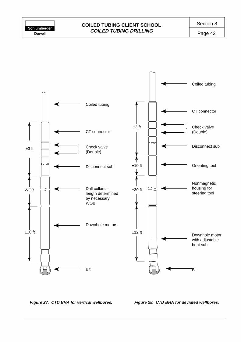
COILED TUBING CLIENT SCHOOLCOILED TUBING DRILLING Page 43
Section 8Schlumberger
Dowell
Figure 27. CTD BHA for vertical wellbores. Figure 28. CTD BHA for deviated wellbores.
CT connector
Disconnect sub
Drill collars –length determinedby necessaryWOB
Downhole motors
Bit
Coiled tubing
CT connector
Disconnect sub
Coiled tubing
Orienting tool
Bit
Downhole motorwith adjustablebent sub
Nonmagnetichousing forsteering tool
Check valve(Double)
Check valve(Double)
±3 ft
WOB
±10 ft
±3 ft
±10 ft
±30 ft
±12 ft
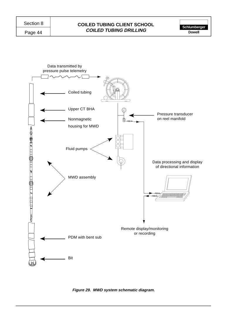
COILED TUBING CLIENT SCHOOLCOILED TUBING DRILLING
Section 8
Page 44Schlumberger
Dowell
MWD assembly
Nonmagnetic
housing for MWD
Upper CT BHA
Coiled tubing
PDM with bent sub
Bit
Pressure transduceron reel manifold
Data processing and displayof directional information
Remote display/monitoringor recording
Fluid pumps
Data transmitted bypressure pulse telemetry
Figure 29. MWD system schematic diagram.

COILED TUBING CLIENT SCHOOLCOILED TUBING DRILLING Page 45
Section 8Schlumberger
Dowell
Wireline steering
tool assembly
Nonmagnetic
housing for
wireline steering
tool
Upper CT BHA
Coiled tubing
PDM with bent sub
Bit
Pressure bulkhead – electricalaccess to tubing
Data processing and displayof directional information
Remote display/monitoringor recording
Fluid pumps
Data transmitted throughwireline inside CT string
Components within reel coreand on reel axle
Reel collector – electricalaccess to rotating reel
Figure 30. Wireline steering system schematic diagram.
COILED TUBING CLIENT SCHOOLCOILED TUBING DRILLING
Section 8
Page 46Schlumberger
Dowell
be monitored and recorded. By combining this informa-tion with the measured depth of the wellbore, theprogress of the wellbore can be compared, and ifnecessary corrections to the planned wellbore profile,can be made by changing the toolface i.e. the relativeposition of the bent housing to the low (or occassionallyhigh) side of the wellbore.
Two steerable systems are commonly used in CTDapplications:
• Wireless steerable BHA including a measurementwhile drilling (MWD) tool.
• Wireline steerable BHA including a wireline steeringtool
MWD Tool/System
The MWD tool sends data to surface by inducing codedpressure pulses in the drilling fluid being pumpedthrough the CT string. The signals recovered at surfaceare decoded and displayed using a PC.
A schematic diagram of the Slim 1 MWD system isshown in Figure 29.
The principal advantage of the MWD system is theabsence of wireline and electrical connections whichare a potential source of problems.
The disadvantage of the MWD system is the slow datarate, i.e., one tool face every 30 seconds, one survey(inclination and azimuth) every 30 minutes. Howeverthis is generally sufficient to control the trajectory of aCTD wellbore. Since the downhole components aresensitive to debris within the drilling fluid, it is generallynecessary to use a high pressure filter system. This istypically located adjacent to the reel manifold.
Wireline Steering Tool
Wireline steering tools are basically the same type oftool as MWDs but data is transmitted to surface througha wireline. The advantage being the high data ratewhich provides almost real time measurement. However,the number of electrical connections required presentsa number of potential problems (Fig. 30).
Some operating conditions, e.g., drilling with foams andgaseous fluids, preclude the the use of MWD systemssince pressure pulses are absorbed by the fluid column.
In such circumstances the wireline steering system andassociated toolstring must be used for directional control.
Monel – Nonmagnetic Drill Collar
A non magnetic tubular is required to house thesteering tool assembly. This typically comprises two 15ft sections of 3-in. OD drill collar made of non magneticmaterial to limit magnetic interference.
Orienting Tool
An orienting tool is necessary to change the orientationof the tool face. The MWD system incorporates anorienting tool which rotates in 30° increments. This toolcan only be used with a wireless steering system.Similar orienting tools are available to be used withwireline steering tools (Sperry Sun and other vendors).They generally provide a low torque, with the toolfacecorrection being made off bottom.
Three main types of orienting tool are currently available
• Pump actuated orienting tools
• Electrically operated orienting tools
• Hydraulically operated orienting tools
Pump actuated orienting tools
The first generation Dowell Anadrill CTD orienting toolis an indexing tool which is actuated by shutting downthe pump, then resuming circulation. Each cycle causesthe lower section of the tool to rotate 30°.
Electrically operated orienting tools
A wireline provides electrical power to a DC motor in theorienting tool which drives a gear train (Dowell, Anadrill,Cobra) or a hydraulic pump (Baker Inteq) to adjust thetool face angle.
These orienting tools provide high torque and allow toolface correction while drilling. Alternative tools areoperated or controlled by electrical or hydraulic systemsthrough cables or conduits installed in the CT string.
•Hydraulically operated orienting tools
A hydraulic orienting tool is operated via hydrauliccontrol line(s) installed in the CT workstring (Camcoand Transocean )

COILED TUBING CLIENT SCHOOLCOILED TUBING DRILLING Page 47
Section 8Schlumberger
Dowell
5.5 Specialized CTD Tools
Float Sub
The float sub (where fitted) is installed above the motorto prevent wellbore fluids from entering the BHA andworkstring. The internal valve closes in the event of akick or underbalanced drilling situation. A Baker 1Rfloat installed in a 3-in. OD sub is recommended.
Drilling Jars
It is recommended that drilling jars are included in aCTD BHA if there is a risk of sticking through formationinstability of differential pressure.
Underreamers
There are two common conditions in whichunderreamers enable a larger hole to be drilled. Inthrough tubing applications where a fixed restrictionlimits the bit size, and in conventional applicationswhere the CT string cannot provide the necessaryWOB. It is not generally recommended that drilling andunderreaming are undertaken at the same time. Instead,it is preferable to drill a pilot hole which is thenunderreamed to the desired size.
The underreamer is positioned in the BHA above the bitor bullnose.
Thruster
Thrusters were developed to avoid the consequencesof the heavy vibration, which is typical of equipmentused in slimhole applications. The thruster dampensvibrations and equalizes the WOB.
Fishing Tools
A selection of fishing tools should be prepared for, or atleast be on stand-by during CTD operations. The natureand size of the fishing tools will be dependent on theCTD BHA to be used and the anticipated downholeconditions. Fishing tools may be needed at any time,appropriate contingency plans should be preparedduring the well planning phase of the operation.
A typical fishing tool selection will include the followingitems.
• GS fishing tool (or similar) – to suit the fishing neck ofthe release joint being used.
• Overshots and spears – available in a variety of sizesand configurations to suit the toolstring in use.
• Junk catchers and magnets – Appropriate precautionsmust be taken at all times to avoid the introduction ofjunk to the wellbore. In addition, it is recommended tohave fishing tools for small items and junk on site at alltimes.
6 MANUFACTURERS AND SUPPLIERS
The following sections lists manufacturers and suppliersof equipment and tools which can be required duringCTD operations. This is prepared for informationpurposes and does not necessarily constitute arecommendation or preference. In most cases, it is theability of available suppliers to provide a reliable andefficient service that determines the ultimate choice ofequipment.
Bits• Baker Hughes• Security• Hycalog• Smith
Motors• Anadrill• Drillex• Baker• Black Max
Steeriable CTD systems• Dowell Anadrill wireless BHA (with Slim 1)• Dowell Anadrill wireline Cobra BHA• Baker Inteq (wire line system)• Sperry Sun (wireless system)• Camco (wire line system)• Drillex (wire line system being devloped)
Fishing Tools and Equipment• Tristate• Enterra
ContentsContents Page Page
1 INTRODUCTION
The primary objective of contingency planning is tominimize response time, or down-time, in the eventunplanned conditions are encountered. In many cases,delays in response to unusual conditions results in aworsening of the circumstances or problem. The potentialrisk to well security and personnel safety can be quicklycompounded in such circumstances. Therefore,contingency planning, in some form, must be part ofevery Dowell CT operation.
The level of contingency planning will generally reflectthe conditions, potential hazards and/or complexity ofthe intended operation; i.e., operations conducted inhigh potential hazard conditions require a higher level ofcontingency planning. In some circumstances, detailedprocedures may be included in contingency plans toensure the safety of personnel and equipment.
The role of contingency planning in CT services isillustrated in Fig. 1 and defined below. The followingdefinitions should be understood by personnel involvedwith the design or execution of Dowell CT services.
COILED TUBING CLIENT SCHOOLPage 1
Appendix ISchlumberger
Dowell
CONTINGENCY PLANNING
1 INTRODUCTION ............................................... 12 CONTINGENCY PLANNING ............................ 2
2.1 Workstring Integrity .................................... 32.1.1 Leak at Surface ............................... 32.1.2 Parted Tubing at Surface................. 42.1.3 Parted Tubing in the Wellbore ......... 42.1.4 Plugged Tubing ............................... 4
2.2 Stuck Workstring ....................................... 42.2.1 Obstruction Going-in-Hole ............... 52.2.2 Stuck Coming Out-of-Hole............... 5
2.3 Mechanically Damaged Tubing ................. 62.3.1 Collapsed Tubing............................. 62.3.2 Damaged Tubing at Surface............ 6
2.4 Pressure Control Equipment ..................... 62.4.1 Stripper Packer Failure .................... 7
• Normal Operating Procedures — Procedures preparedto ensure correct execution of the intended operationin a safe manner. Job procedures or guidelines mustbe prepared for every CT operation, and will generallycomprise a sequence of actions, checks or controls.
• Contingency Plans — Contingency plans should beprepared as a reference source to be used as a guidein the event unplanned conditions are encounteredduring an operation. By necessity, some plans mayinclude emergency procedures required to maintaincontrol of well pressure or surface equipment. However,CTU operators must be fully familiar with suchemergency procedures, and be capable of conductingthem without reference to prepared plans orprocedures.
• Emergency Procedures — Emergency proceduresmay be defined as immediate responses to conditionswhich threaten well security, or personnel safety.Such responses are enacted as a result of detailedtraining, familiarity with equipment and executed withthe knowledge and awareness of the wellbore andoperational conditions.
2.4.2 Leak in Riser Below BOP ................ 72.4.3 Leak in Riser Above BOP ................ 8
2.5 Coiled Tubing Equipment .......................... 82.5.1 Loss of Power .................................. 82.5.2 Reel Swivel Leak ............................. 8
2.6 Operational Considerations ....................... 82.7 Stuck Point Assessment ............................ 92.8 Cutting the Workstring at Surface.............. 9
2.8.1 Downhole Cut Preparation .............. 102.8.2 Explosive Cutters ............................. 102.8.3 Chemical Cutters ............................. 102.8.4 Coiled Tubing Retrieval ................... 13
3 EMERGENCY PROCEDURES ........................ 144 REFERENCES ................................................. 14

COILED TUBING CLIENT SCHOOLCOILED TUBING CONTINGENCY PLANNING
Appendix I
Page 2Schlumberger
Dowell
Figure 1. Coiled tubing services contingency planning
In each of the above, consideration must be given tothree key areas of responsability.
• Well Security
• Personnel Safety
• Equipment, Tools and the Intended Operation
As a supplement to any contingency plans, the sourceand availability of any special equipment or servicesshould be noted (e.g., chemical cutting services).
2 CONTINGENCY PLANNING
Due to the high number of variables, it is impractical todetail all aspects of contingency planning required forCT services. The following guidelines are provided to
assist with the preparation of contingency plans whichshould be specifically designed for each operation orcampaign.
Several actions outlined in the contingency plans involvethe participation of additional personnel or departments(e.g., The involvement of production facilities andpersonnel when flowing a well to reduce wellheadpressure). Therefore the requirements, and/or limitations,of related facilities and personnel must be consideredduring the preparation of contingency plans.
For the purpose of presentation the contingencyguidelines are categorized as follows.
• Workstring Integrity
• Stuck or Damaged Workstring
COILED TUBING SERVICES – PROCEDURES AND PLANNING
A sequence of actions, checks and controlsto ensure correct execution of the intended operation.
Normal Operating Procedures
Emergency Procedures
Trained responses to conditionswhich jeopardize the safety of
personnel or security of the wellbore.
Contingency Plans
A reference source to be used as a guide inthe event reasonably forseeable, butunplanned conditions are encountered
during the operation.
Well SecurityPersonnel Safety
Equipment and Tools
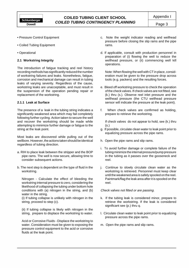
COILED TUBING CLIENT SCHOOLCOILED TUBING CONTINGENCY PLANNING Page 3
Appendix ISchlumberger
Dowell
• Pressure Control Equipment
• Coiled Tubing Equipment
• Operational
2.1 Workstring Integrity
The introduction of fatigue tracking and reel historyrecording methods has significantly reduced the numberof workstring failures and leaks. Nonetheless, fatigue,corrosion and mechanical damage can result in tubingleaks of varying severity. Regardless of the cause,workstring leaks are unacceptable, and must result inthe suspension of the operation pending repair orreplacement of the workstring.
2.1.1 Leak at Surface
The presence of a leak in the tubing string indicates asignificantly weakened area which may fail completelyfollowing further cycling. Action taken to secure the welland recover the workstring should be made whileattempting to minimize further damage or fatigue to thestring at the leak point.
Most leaks are discovered while pulling out of thewellbore. However, the actions taken should be identicalregardless of tubing direction.
a. RIH to place leak between the stripper and the BOPpipe rams. The well is now secure, allowing time toconsider subsequent actions.
b. The next step is dependent on the type of fluid in theworkstring.
Nitrogen - Calculate the effect of bleeding theworkstring internal pressure to zero, considering thelikelihood of collapsing the tubing under bottom holeconditions with (a) nitrogen in the string, and (b)water in the string.(i) If tubing collapse is unlikely with nitrogen in thestring, proceed to step (c).
(ii) If tubing collapse is likely with nitrogen in thestring, prepare to displace the workstring to water.
Acid or Corrosive Fluids - Displace the workstring towater. Consideration must be given to exposing thepressure control equipment to the acid or corrosivefluids at the leak point.
c. Note the weight indicator reading and wellheadpressure before closing the slip rams and the piperams.
d. If applicable, consult with production personnel inpreparation of (i) flowing the well to reduce thewellhead pressure, or (ii) commencing well killoperations.
Note: When flowing the well with CT in place, consid-eration must be given to the pressure drop acrosstools (e.g. packers) and the resulting forces.
e. Bleed off workstring pressure to check the operationof the check valves. If check valves are not fitted, see(k.) thru (s.). Observe reel inlet pressure and thewellhead pressure (the CTU wellhead pressuresensor will indicate the pressure at the leak point).
f. When check valves are confirmed as holding,prepare to retrieve the workstring.
If check valves do not appear to hold, see (k.) thru(s.)
g. If possible, circulate clean water to leak point prior toequalizing pressure across the pipe rams.
h. Open the pipe rams and slip rams.
i. To avoid further damage or complete failure of thetubing minimize the internal pressure/pump pressurein the tubing as it passes over the gooseneck andreel.
j. Continue to slowly circulate clean water as theworkstring is retrieved. Personnel must keep clearuntil the weakened area is safely spooled on the reel.Paintmark/flag the leak area after it is spooled on thereel.
Check valves not fitted or are passing.
k. If the tubing leak is considered minor, prepare toretrieve the workstring. If the leak is consideredsignificant see (p.) thru q.
l. Circulate clean water to leak point prior to equalizingpressure across the pipe rams.
m. Open the pipe rams and slip rams.

COILED TUBING CLIENT SCHOOLCOILED TUBING CONTINGENCY PLANNING
Appendix I
Page 4Schlumberger
Dowell
n. To avoid further damage or complete failure of thetubing minimize the internal pressure/pump pressurein the tubing as it passes over the gooseneck andreel.
o. To avoid migration of well fluids continue to slowlycirculate clean water as the workstring is retrieved.Personnel must keep clear until the weakened areais safely spooled on the reel. Paintmark/flag the leakarea after it is spooled on the reel.
Severe leak - check valves not fitted or are passing.
p. If the tubing leak is considered severe, prepare to killthe well.
q. If possible, kill the well leaving the workstring intact.Use the workstring to circulate kill weight fluid.
2.1.2 Parted Tubing at Surface
There are two major concerns associated with theworkstring parting on surface. One issue is well securityand the presence of a tube extending through thewellhead. However, an instantaneous hazard exists asthe free end(s) of the tubing react to the workstringinternal pressure. Operator reaction to such eventsshould be instinctive.
a. Stop injector head and shut down pumping equipment.
b. If the tubing has parted and fallen through the stripperBOP, (typical overpull break) close the blind rams toregain control of the well. Shut in well, as allowed byposition of tubing, and prepare for well kill and orfishing.
If the tubing is supported by the chains, close the sliprams and pipe rams.
c. Confirm that the check valves are holding. If checkvalves were not used, or are passing, close the shearrams, withdraw the tubing stub and close the blindrams to regain control of the well.
d. Kill the well.
e. Withdraw sufficient tubing to allow a cold roll connectorto be fitted. Retrieve the workstring.
2.1.3 Parted Tubing in the Wellbore
A workstring which has parted in the wellbore willgenerally be indicated by a sudden change in the weightindicator (weight loss) and/or a variation in circulatingpressure. Attempting to tag a known restriction mayconfirm the tubing has parted, if the apparent depth isgreater than previously noted.
In some cases the first indication that the workstring hasparted will be the release of well fluids as the tubing stubis pulled through the stripper. In this event, closing theblind rams will regain control of the well.
a. On suspicion that the workstring has parted in thewellbore, attempt to asses the length of tubing re-maining. The loss of a heavy toolstring below the CTconnector may give similar indications to a partedworkstring.
b. Kill the well.
c. Slowly recover the remaining tubing. Close the blindrams when the stub has been withdrawn.
2.1.4 Plugged Tubing
Most CT applications require fluids to be circulated,either as part of the treatment or to maintain wellconditions suitable for continuing the operation (e.g., toprevent tubing collapse).
2.2 Stuck Workstring
There are many ways by which a workstring can becomestuck. In addition, the term stuck is often applied to anumber of conditions all of which impede the progressof the CT operation (e.g., severe overpull or under-weight conditions, stuck down - free up, stuck up - freedown, stuck up - stuck down)
Selection of the appropriate action or treatment toresolve the condition depends on several factors. Thefollowing points should be considered.
• Wellbore geometry
• CT toolstring geometry
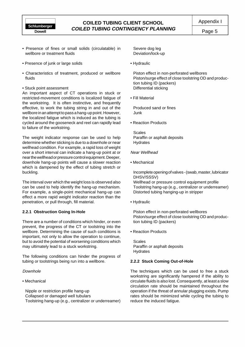
COILED TUBING CLIENT SCHOOLCOILED TUBING CONTINGENCY PLANNING Page 5
Appendix ISchlumberger
Dowell
• Presence of fines or small solids (circulatable) inwellbore or treatment fluids
• Presence of junk or large solids
• Characteristics of treatment, produced or wellborefluids
• Stuck point assessmentAn important aspect of CT operations in stuck orrestricted-movement conditions is localized fatigue ofthe workstring. It is often instinctive, and frequentlyeffective, to work the tubing string in and out of thewellbore in an attempt to pass a hang-up point. However,the localized fatigue which is induced as the tubing iscycled around the gooseneck and reel can rapidly leadto failure of the workstring.
The weight indicator response can be used to helpdetermine whether sticking is due to a downhole or nearwellhead condition. For example, a rapid loss of weightover a short interval can indicate a hang-up point at ornear the wellhead or pressure control equipment. Deeper,downhole hang-up points will cause a slower reactionwhich is dampened by the effect of tubing stretch orbuckling.
The interval over which the weight loss is observed alsocan be used to help identify the hang-up mechanism.For example, a single-point mechanical hang-up caneffect a more rapid weight indicator reaction than thepenetration, or pull through, fill material.
2.2.1 Obstruction Going In-Hole
There are a number of conditions which hinder, or evenprevent, the progress of the CT or toolstring into thewellbore. Determining the cause of such conditions isimportant, not only to allow the operation to continue,but to avoid the potential of worsening conditions whichmay ultimately lead to a stuck workstring.
The following conditions can hinder the progress oftubing or toolstrings being run into a wellbore.
Downhole
• Mechanical
Nipple or restriction profile hang-upCollapsed or damaged well tubularsToolstring hang-up (e.g., centralizer or underreamer)
Severe dog legDeviation/lock-up
• Hydraulic
Piston effect in non-perforated wellboresPiston/surge effect of close toolstring OD and produc-tion tubing ID (packers)Differential sticking
• Fill Material
Produced sand or finesJunk
• Reaction Products
ScalesParaffin or asphalt depositsHydrates
Near Wellhead
• Mechanical
Incomplete opening of valves - (swab, master, lubricatorDHSV/SSSV)Wellhead or pressure control equipment profileToolstring hang-up (e.g., centralizer or underreamer)Distorted tubing hanging-up in stripper
• Hydraulic
Piston effect in non-perforated wellboresPiston/surge effect of close toolstring OD and produc-tion tubing ID (packers)
• Reaction Products
ScalesParaffin or asphalt depositsHydrates
2.2.2 Stuck Coming Out-of-Hole
The techniques which can be used to free a stuckworkstring are significantly hampered if the ability tocirculate fluids is also lost. Consequently, at least a slowcirculation rate should be maintained throughout theoperation if the threat of annular plugging exists. Pumprates should be minimized while cycling the tubing toreduce the induced fatigue.
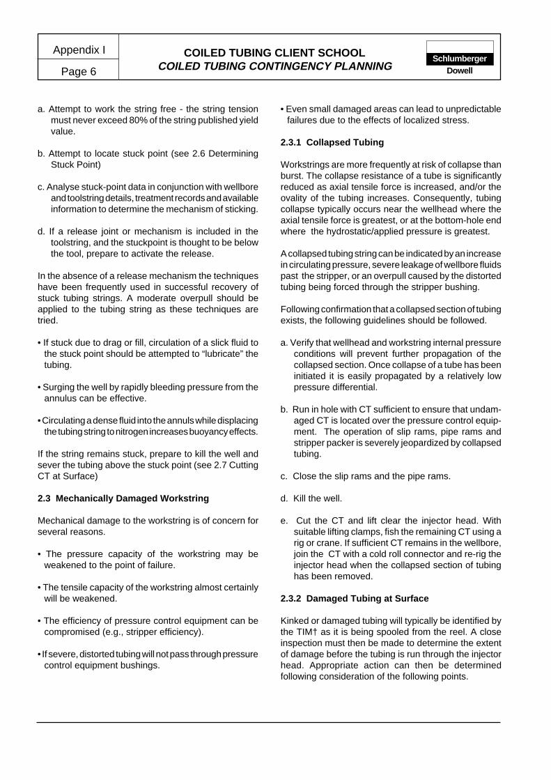
COILED TUBING CLIENT SCHOOLCOILED TUBING CONTINGENCY PLANNING
Appendix I
Page 6Schlumberger
Dowell
a. Attempt to work the string free - the string tensionmust never exceed 80% of the string published yieldvalue.
b. Attempt to locate stuck point (see 2.6 DeterminingStuck Point)
c. Analyse stuck-point data in conjunction with wellboreand toolstring details, treatment records and availableinformation to determine the mechanism of sticking.
d. If a release joint or mechanism is included in thetoolstring, and the stuckpoint is thought to be belowthe tool, prepare to activate the release.
In the absence of a release mechanism the techniqueshave been frequently used in successful recovery ofstuck tubing strings. A moderate overpull should beapplied to the tubing string as these techniques aretried.
• If stuck due to drag or fill, circulation of a slick fluid tothe stuck point should be attempted to “lubricate” thetubing.
• Surging the well by rapidly bleeding pressure from theannulus can be effective.
• Circulating a dense fluid into the annuls while displacingthe tubing string to nitrogen increases buoyancy effects.
If the string remains stuck, prepare to kill the well andsever the tubing above the stuck point (see 2.7 CuttingCT at Surface)
2.3 Mechanically Damaged Workstring
Mechanical damage to the workstring is of concern forseveral reasons.
• The pressure capacity of the workstring may beweakened to the point of failure.
• The tensile capacity of the workstring almost certainlywill be weakened.
• The efficiency of pressure control equipment can becompromised (e.g., stripper efficiency).
• If severe, distorted tubing will not pass through pressurecontrol equipment bushings.
• Even small damaged areas can lead to unpredictablefailures due to the effects of localized stress.
2.3.1 Collapsed Tubing
Workstrings are more frequently at risk of collapse thanburst. The collapse resistance of a tube is significantlyreduced as axial tensile force is increased, and/or theovality of the tubing increases. Consequently, tubingcollapse typically occurs near the wellhead where theaxial tensile force is greatest, or at the bottom-hole endwhere the hydrostatic/applied pressure is greatest.
A collapsed tubing string can be indicated by an increasein circulating pressure, severe leakage of wellbore fluidspast the stripper, or an overpull caused by the distortedtubing being forced through the stripper bushing.
Following confirmation that a collapsed section of tubingexists, the following guidelines should be followed.
a. Verify that wellhead and workstring internal pressureconditions will prevent further propagation of thecollapsed section. Once collapse of a tube has beeninitiated it is easily propagated by a relatively lowpressure differential.
b. Run in hole with CT sufficient to ensure that undam-aged CT is located over the pressure control equip-ment. The operation of slip rams, pipe rams andstripper packer is severely jeopardized by collapsedtubing.
c. Close the slip rams and the pipe rams.
d. Kill the well.
e. Cut the CT and lift clear the injector head. Withsuitable lifting clamps, fish the remaining CT using arig or crane. If sufficient CT remains in the wellbore,join the CT with a cold roll connector and re-rig theinjector head when the collapsed section of tubinghas been removed.
2.3.2 Damaged Tubing at Surface
Kinked or damaged tubing will typically be identified bythe TIM† as it is being spooled from the reel. A closeinspection must then be made to determine the extentof damage before the tubing is run through the injectorhead. Appropriate action can then be determinedfollowing consideration of the following points.

COILED TUBING CLIENT SCHOOLCOILED TUBING CONTINGENCY PLANNING Page 7
Appendix ISchlumberger
Dowell
• Extent of damage
• Location of damage
• Intended application and anticipated forces
• Availability of a substitute reel
2.4 Pressure Control Equipment
The application and control of pressure control equipmentis typically regulated by local or national authorities.Should the integrity or efficiency of the equipment be indoubt, the intended operation must be suspended andthe well secured until all pressure control equipmentrequirements are met.
The equipment configuration may allow several optionsto be considered in overcoming malfunctions or failures.However, it is generally required that two barriers againstwell fluids and pressure be in place at all times. Thepriority in contingency planning or emergency proceduresmust be to maintain or regain the required level ofprotection before proceeding with the operation.
2.4.1 Stripper Packer Failure
Gross leaks at the stripper packer are easily identifiableand cause obvious safety and environmental hazards.Less severe leaks can be more difficult to detect,especially if the injector head is poorly lit or somedistance from the control cabin. However, such leakscan still pose a significant hazard and should be rectifiedas soon as possible.
a. If a tandem or dual stripper is fitted, energize theremaining stripper packer to maintain control of thewell. Replace the failed stripper packer at the earliestopportunity the operation will allow.
If a single stripper is being used, close the slip ramsand pipe rams to regain control of the well. On highpressure gas wells, close the pipe rams first. Swiftaction reduces the risk of the cutting or damaging theram seals during closure against an increasing flow.
b. On applications with a high wellhead pressure,consider flowing the well to reduce wellhead pressurewhile repairs are made.
c. Replace the stripper packing element. On top loadingstripper models it is necessary to hang off the string
from the slip rams and bleed off inside chain tensionto facilitate removal of the stripper bushings orpacker.
d. Energize the stripper packer. If possible, pressuretest packer to 80% of wellhead pressure.
e. Equalize pressure across the pipe rams, pick upstring weight and open the slip rams.
2.4.2 Leak in Riser/Lubricator Above BOP
Leaks in the riser or lubricator section above the BOPare often caused by an unstable equipment rig-up whichcan result in high bending moments being exerted onconnections or flanges. In the event of a leak, thestability of the equipment rig-up must be checked andimproved as necessary.
a. Carefully stop the injector head to avoid furtherstressing the leak point.
b. Close the slip rams and pipe rams to regain controlof the well. In the case of severe leak, close the piperams first to minimize exposure and effect of wellborefluids.
c. Bleed-off the remaining pressure above the piperams and monitor to ensure that the pipe rams arefunctioning.
d. On applications with a high wellhead pressure,consider flowing the well to reduce wellhead pressurewhile repairs are made.
e. For a flanged connection, stabilize the injector headand check/re-torque the flange bolts.
For pin and collar connections, assess the feasibilityof breaking the connection to fit (cut and join) a newO-ring. This is generally only feasible where theinjector head is supported and stabilized by a mastor jacking frame. Since this process requires theinjector head to be raised while the tubing is held inthe slips it may only be completed safely where nowellhead pressure exists.
If the leak cannot be repaired assess the leak.
Slight Leak Conditions
f. If pumping equipment is available, begin pumping aninert fluid into the BOP kill port and POOH as quickly
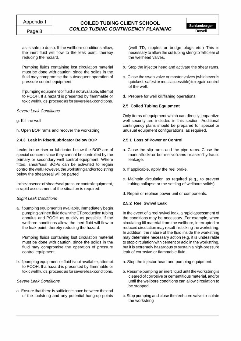
COILED TUBING CLIENT SCHOOLCOILED TUBING CONTINGENCY PLANNING
Appendix I
Page 8Schlumberger
Dowell
as is safe to do so. If the wellbore conditions allow,the inert fluid will flow to the leak point, therebyreducing the hazard.
Pumping fluids containing lost circulation materialmust be done with caution, since the solids in thefluid may compromise the subsequent operation ofpressure control equipment.
If pumping equipment or fluid is not available, attemptto POOH. If a hazard is presented by flammable ortoxic well fluids, proceed as for severe leak conditions.
Severe Leak Conditions
g. Kill the well
h. Open BOP rams and recover the workstring
2.4.3 Leak in Riser/Lubricator Below BOP
Leaks in the riser or lubricator below the BOP are ofspecial concern since they cannot be controlled by theprimary or secondary well control equipment. Wherefitted, shear/seal BOPs can be activated to regaincontrol the well. However, the workstring and/or toolstringbelow the shear/seal will be parted
In the absence of shear/seal pressure control equipment,a rapid assessment of the situation is required.
Slight Leak Conditions
a. If pumping equipment is available, immediately beginpumping an inert fluid down the CT production tubingannulus and POOH as quickly as possible. If thewellbore conditions allow, the inert fluid will flow tothe leak point, thereby reducing the hazard.
Pumping fluids containing lost circulation materialmust be done with caution, since the solids in thefluid may compromise the operation of pressurecontrol equipment.
b. If pumping equipment or fluid is not available, attemptto POOH. If a hazard is presented by flammable ortoxic well fluids, proceed as for severe leak conditions.
Severe Leak Conditions
a. Ensure that there is sufficient space between the endof the toolstring and any potential hang-up points
(well TD, nipples or bridge plugs etc.) This isnecessary to allow the cut tubing string to fall clear ofthe wellhead valves.
b. Stop the injector head and activate the shear rams.
c. Close the swab valve or master valves (whichever isquickest, safest or most accessible) to regain controlof the well.
d. Prepare for well kill/fishing operations.
2.5 Coiled Tubing Equipment
Only items of equipment which can directly jeopardizewell security are included in this section. Additionalcontingency plans should be prepared for special orunusual equipment configurations, as required.
2.5.1 Loss of Power or Control
a. Close the slip rams and the pipe rams. Close themanual locks on both sets of rams in case of hydraulicleakage.
b. If applicable, apply the reel brake.
c. Maintain circulation as required (e.g., to preventtubing collapse or the settling of wellbore solids)
d. Repair or replace power unit or components.
2.5.2 Reel Swivel Leak
In the event of a reel swivel leak, a rapid assessment ofthe conditions may be necessary. For example, whencirculating fill material from the wellbore, interrupted orreduced circulation may result in sticking the workstring.In addition, the nature of the fluid inside the workstringmay determine necessary action (e.g. it is undesirableto stop circulation with cement or acid in the workstring,but it is extremely hazardous to sustain a high-pressureleak of corrosive or flammable fluid.
a. Stop the injector head and pumping equipment.
b. Resume pumping an inert liquid until the workstring iscleared of corrosive or cementitious material, and/oruntil the wellbore conditions can allow circulation tobe stopped.
c. Stop pumping and close the reel-core valve to isolatethe workstring

COILED TUBING CLIENT SCHOOLCOILED TUBING CONTINGENCY PLANNING Page 9
Appendix ISchlumberger
Dowell
d. If required repair/replace the swivel, pressure test theassembly and proceed with the operation.
2.6 Operational
Some consideration must be given to possible eventsconcerning the operation which may be reasonablyforeseeable. The following list of wellbore or treatmentconditions can be considered as foreseeable in certaincircumstances.
Circulating Applications
Lost circulation/returnsWell/formation kickInterruption to fluid supplyInsufficient fluid supply (rate or volume)Treatment fluid out of specified limitsUnable to penetrate/RIH
Downhole Tool Operations
Suspected tool failure/malfunctionUnable to penetrate/RIHDepth correlation appears incorrect
2.7 Determining the Stuck Point
When attempting to free a stuck workstring it is necessaryto determine, as accurately as possible, the point atwhich the workstring is held. The completion, or wellgeometry, data are generally good indicators of potentialstuck points. However, if possible, a stretch test/calculation should be conducted to confirm/determinethe stuck point.
The worksheets shown in Fig. 2 and Fig. 3 are intendedto help record and calculate the data required todetermine the CT stuck point. The accuracy of thistechnique is greatly dependent on the accuracy of theinformation input. Therefore, it is essential that accurateinformation is gathered on tapered string dimensions,etc., before applying the calculation.
CT Stretch
The following procedure should be used to determinethe stretch (∆l) in the CT string.
a. Apply sufficient tension to the tubing to ensure thatthe string is in tension at the stuck point.
b. Mark the CT just above the stripper.
c. Apply additional tension (10,000 lb if possible, butnever exceed 80% of the string yield tension).
d. Accurately measure the tubing stretch by measuringthe distance the mark has moved. Note the exactadditional tension applied.
Nontapered String
The approximate location of the stuck point on a non-tapered string may be calculated by following thecalculation procedure shown in Fig.2.
Tapered String
To accurately determine the location of the stuck pointof a tapered string, the length and cross-sectional areaof each taper section in the well must be known.
The stretch resulting from the applied load is thencalculated for each taper section. This series ofcalculations should begin with the top taper section andprogress through the deeper sections until the sum ofthe calculated section stretches is greater, or equal to,the actual measured stretch.
The calculation procedures shown in Fig. 2 and Fig. 3should then be used to determine the stuck point locationon a tapered CT string.
2.8 Cutting the Coiled Tubing at Surface
Before the CT is cut at the surface, the well must bekilled. If possible, this should be conducted by circulatingthrough the CT. This will maintain a kill-weight columnof fluid inside and outside the CT string.
If circulation is not possible, bullhead the kill fluid downthe annulus. In this event, account must be taken of theinjection pressure limits imposed by the well tubularsand equipment, and the risk of collapsing the CT.
Once the well has been killed, the following procedureshould be followed.
a. Confirm the status of the well by conducting a 30 minflow check on the annulus and the CT at the reelmanifold. If practical, a heavier fluid should be spottedin the CT string to avoid any “U” tube effect fromflowing fluid when the cut is made at the injectorhead.
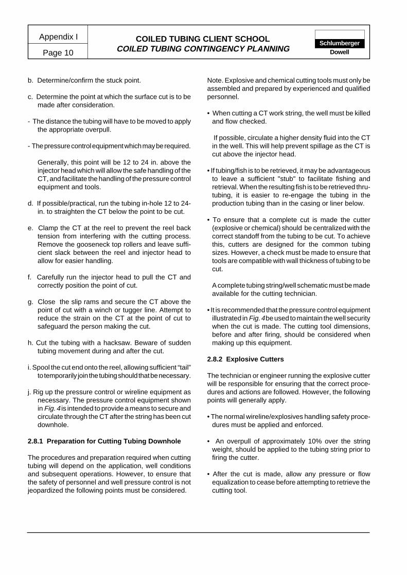
COILED TUBING CLIENT SCHOOLCOILED TUBING CONTINGENCY PLANNING
Appendix I
Page 10Schlumberger
Dowell
b. Determine/confirm the stuck point.
c. Determine the point at which the surface cut is to bemade after consideration.
- The distance the tubing will have to be moved to applythe appropriate overpull.
- The pressure control equipment which may be required.
Generally, this point will be 12 to 24 in. above theinjector head which will allow the safe handling of theCT, and facilitate the handling of the pressure controlequipment and tools.
d. If possible/practical, run the tubing in-hole 12 to 24-in. to straighten the CT below the point to be cut.
e. Clamp the CT at the reel to prevent the reel backtension from interfering with the cutting process.Remove the gooseneck top rollers and leave suffi-cient slack between the reel and injector head toallow for easier handling.
f. Carefully run the injector head to pull the CT andcorrectly position the point of cut.
g. Close the slip rams and secure the CT above thepoint of cut with a winch or tugger line. Attempt toreduce the strain on the CT at the point of cut tosafeguard the person making the cut.
h. Cut the tubing with a hacksaw. Beware of suddentubing movement during and after the cut.
i. Spool the cut end onto the reel, allowing sufficient “tail”to temporarily join the tubing should that be necessary.
j. Rig up the pressure control or wireline equipment asnecessary. The pressure control equipment shownin Fig. 4 is intended to provide a means to secure andcirculate through the CT after the string has been cutdownhole.
2.8.1 Preparation for Cutting Tubing Downhole
The procedures and preparation required when cuttingtubing will depend on the application, well conditionsand subsequent operations. However, to ensure thatthe safety of personnel and well pressure control is notjeopardized the following points must be considered.
Note. Explosive and chemical cutting tools must only beassembled and prepared by experienced and qualifiedpersonnel.
• When cutting a CT work string, the well must be killedand flow checked.
If possible, circulate a higher density fluid into the CTin the well. This will help prevent spillage as the CT iscut above the injector head.
• If tubing/fish is to be retrieved, it may be advantageousto leave a sufficient "stub" to facilitate fishing andretrieval. When the resulting fish is to be retrieved thru-tubing, it is easier to re-engage the tubing in theproduction tubing than in the casing or liner below.
• To ensure that a complete cut is made the cutter(explosive or chemical) should be centralized with thecorrect standoff from the tubing to be cut. To achievethis, cutters are designed for the common tubingsizes. However, a check must be made to ensure thattools are compatible with wall thickness of tubing to becut.
A complete tubing string/well schematic must be madeavailable for the cutting technician.
• It is recommended that the pressure control equipmentillustrated in Fig. 4 be used to maintain the well securitywhen the cut is made. The cutting tool dimensions,before and after firing, should be considered whenmaking up this equipment.
2.8.2 Explosive Cutters
The technician or engineer running the explosive cutterwill be responsible for ensuring that the correct proce-dures and actions are followed. However, the followingpoints will generally apply.
• The normal wireline/explosives handling safety proce-dures must be applied and enforced.
• An overpull of approximately 10% over the stringweight, should be applied to the tubing string prior tofiring the cutter.
• After the cut is made, allow any pressure or flowequalization to cease before attempting to retrieve thecutting tool.

COILED TUBING CLIENT SCHOOLCOILED TUBING CONTINGENCY PLANNING Page 11
Appendix ISchlumberger
Dowell
Figure 2. Stuck point calculation worksheet.
L = A E ∆l12 F
Length to Stuck Point
(OD - ID )2 2
4πA – Cross-Sectional Area =
∆l – Stretch
L – Length to Struck Point
F – Applied Load (at the time the CT stretch was measured at surface)
E – Constant for Young's Modulus of Elasticity (29,000,000)
12 x ( Applied Load)....................(lb)= Length to Stuck Point = .......................(ft)
Cross-Sectional Area.....................(in. ) x 29,000,000 x Stretch......................(in.)2
COILED TUBING STRING STUCK-POINT CALCULATION WORKSHEET
NONTAPERED STRING
TAPERED STRING
L = A E ∆l12 F
Length to Stuck Point
(OD - ID )2 2
4πA – Cross-Sectional Area =
∆l – Measured Stretch
L – Length to Struck Point
F – Applied Load (at the time the CT stretch was measured at surface)
E – Constant for Young's Modulus of Elasticity (29,000,000)
12 x ( Applied Load)....................(lb)= Length to Stuck Point = .......................(ft)
Cross-Sectional Area.....................(in. ) x 29,000,000 x Stretch......................(in.)2
Length of CT in the Well.......................(ft)
Measured Stretch.......................(in.) at Applied Load..............................(lb)
1. Determine the actual tubing string stretch for a given load.
Using the calculation form overleaf, determine the taper section in which the stuck point is located. Starting with the top section,calculate and add the stretch induced in each taper section until the sum is greater or equal to the actual measured stretch.
Determine the location of the stuck point in the last taper section by applying the following formula. The value for ∆l (Stretch) is obtained by subtracting the sum of the free taper sections calculated stretch from the measured stretch.
Add this length to the lengths of the free taper sections.
2.
3.
4. Taper Section No. 1 Length .......................(ft)
Taper Section No. 2 Length .......................(ft)
Taper Section No. 3 Length .......................(ft)
Taper Section No. 4 Length .......................(ft)
Taper Section No. 5 Length .......................(ft)
Length from Stuck Point to the Last Taper Section .......................(ft)
Total Length to Stuck Point .......................(ft)

COILED TUBING CLIENT SCHOOLCOILED TUBING CONTINGENCY PLANNING
Appendix I
Page 12Schlumberger
Dowell
Figure 3. Stuck point calculation - tapered string worksheet.
Weld Location.................(ft)
Wall Thickness................(in.)
Cross-Sectional Area (A)...................(in. ) A =
Taper Section No. 1 Length .......................(ft)
(OD - ID )2 2
4π
Length of CT in the Well.......................(ft)
COILED TUBING STRING STUCK POINT CALCULATION TAPERED STRING WORKSHEET
Weld Location.................(ft)
Wall Thickness................(in.)
Cross-Sectional Area (A)...................(in. ) A =
Taper Section No. 2 Length .......................(ft)
(OD - ID )2 2
4π
Weld Location.................(ft)
Wall Thickness................(in.)
Cross-Sectional Area (A)...................(in. ) A =
Taper Section No. 4 Length .......................(ft)
(OD - ID )2 2
4π
Weld Location.................(ft)
Wall Thickness................(in.)
Cross-Sectional Area (A)...................(in. ) A =
Taper Section No. 5 Length .......................(ft)
(OD - ID )2 2
4π
Measured Stretch.......................(in.) at Applied Load..............................(lb)
Tubing Stretch in Taper Section No. 1 ∆l = 12 F L
AE
∆l – Stretch
12 x ( Applied Load)....................(lb) x Taper Section Length .............................(ft)
Taper Section Stretch = ........................(in.)
Tubing Stretch in Taper Section No. 2 ∆l = 12 F L
AE
Taper Section Stretch = ........................(in.)
Tubing Stretch in Taper Section No. 3 ∆l = 12 F L
AE
Taper Section Stretch = ........................(in.)
Tubing Stretch in Taper Section No. 4 ∆l = 12 F L
AE
Taper Section Stretch = ........................(in.)
Tubing Stretch in Taper Section No. 5 ∆l = 12 F L
AE
Taper Section Stretch = ........................(in.)
L – Length of Taper Section
F – Applied Load (At the time the CT stretch was measured at surface.
A – Cross-sectional Area of the CT Taper Section
E – Constant for Young's Modulus of Elasticity
12 x ( Applied Load)....................(lb) x Taper Section Length .............................(ft)
12 x ( Applied Load)....................(lb) x Taper Section Length .............................(ft)
12 x ( Applied Load)....................(lb) x Taper Section Length .............................(ft)
12 x ( Applied Load)....................(lb) x Taper Section Length .............................(ft)
Cross-Sectional Area.....................(in. ) x 29,000,0002
Weld Location.................(ft)
Wall Thickness................(in.)
Cross-Sectional Area (A)...................(in. ) A =
Taper Section No. 3 Length .......................(ft)
(OD - ID )2 2
4π
2
2
2
2
2
Cross-Sectional Area.....................(in. ) x 29,000,0002
Cross-Sectional Area.....................(in. ) x 29,000,0002
Cross-Sectional Area.....................(in. ) x 29,000,0002
Cross-Sectional Area.....................(in. ) x 29,000,0002
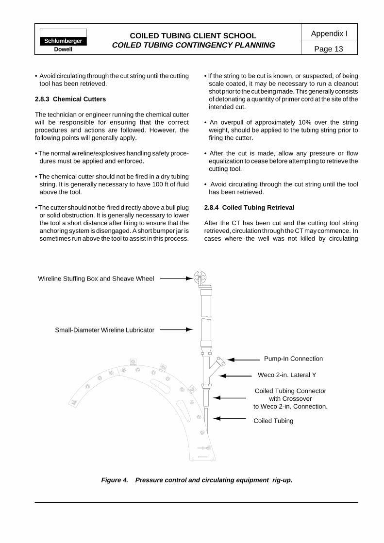
COILED TUBING CLIENT SCHOOLCOILED TUBING CONTINGENCY PLANNING Page 13
Appendix ISchlumberger
Dowell
• Avoid circulating through the cut string until the cuttingtool has been retrieved.
2.8.3 Chemical Cutters
The technician or engineer running the chemical cutterwill be responsible for ensuring that the correctprocedures and actions are followed. However, thefollowing points will generally apply.
• The normal wireline/explosives handling safety proce-dures must be applied and enforced.
• The chemical cutter should not be fired in a dry tubingstring. It is generally necessary to have 100 ft of fluidabove the tool.
• The cutter should not be fired directly above a bull plugor solid obstruction. It is generally necessary to lowerthe tool a short distance after firing to ensure that theanchoring system is disengaged. A short bumper jar issometimes run above the tool to assist in this process.
• If the string to be cut is known, or suspected, of beingscale coated, it may be necessary to run a cleanoutshot prior to the cut being made. This generally consistsof detonating a quantity of primer cord at the site of theintended cut.
• An overpull of approximately 10% over the stringweight, should be applied to the tubing string prior tofiring the cutter.
• After the cut is made, allow any pressure or flowequalization to cease before attempting to retrieve thecutting tool.
• Avoid circulating through the cut string until the toolhas been retrieved.
2.8.4 Coiled Tubing Retrieval
After the CT has been cut and the cutting tool stringretrieved, circulation through the CT may commence. Incases where the well was not killed by circulating
Coiled Tubing Connectorwith Crossover
to Weco 2-in. Connection.
Coiled Tubing
Weco 2-in. Lateral Y
Pump-In Connection
Small-Diameter Wireline Lubricator
Wireline Stuffing Box and Sheave Wheel
Figure 4. Pressure control and circulating equipment rig-up.

COILED TUBING CLIENT SCHOOLCOILED TUBING CONTINGENCY PLANNING
Appendix I
Page 14Schlumberger
Dowell
through the CT, at least 1-1/2 wellbore volumes shouldbe circulated to ensure that a continuous column of therequired kill-weight fluid exists.
Prior to rigging down the pressure control equipment, aflow test should be conducted to verify the well status.
To recover the cut tubing string, the tubing must bejoined temporarily by a double roll-on connector. Thiswill allow the tubing to be spooled onto the reel. The reel-drive hydraulic circuit should be operated at a reducedbackpressure until the tubing joint is three to four wrapson the reel.
An accurate track of the tubing recovered must be keptto avoid withdrawing the end from the injector chains.Howver, in most cases, tubing cut by an explosive cutterwill not pass through the stripper.
Further explanation of the equipment and techniquesused for cutting CT may be found in the references listedin Section 4.
3 EMERGENCY PROCEDURES
The objective of emergency procedures is to secureexisting or potentially hazardous conditions sufficient toenable a review of possible options (contingency plans)to be safely made. The procedures must be executedwith minimal delay or consultation and are typicallyassociated with the operation of well pressure controlequipment or devices. Consequently, all CTU operatorsmust be fully familiar with the equipment in use. Inaddition, operators should be constantly aware of currentand potential well conditions.
4 REFERENCES
The following references are recommended for jobdesign information or for further reading.
Internal Technical Manuals (ITM)
Coiled Tubing Operators Manual. ITM-1099. 1992
Safety and Loss Prevention Manual. HSE-8005. 1991
Coiled Tubing Equipment STEM I - June 1992

Appendix II
Page 1COILED TUBING CLIENT SCHOOL MANUAL
DEPLOYMENT SYSTEMS
ContentsPageContents Page
SchlumbergerDowell
* Mark of Schlumberger
INTRODUCTION ......................................... 11 LUBRICATOR DEPLOYMENT .................... 12 TOOL DEPLOYMENT SYSTEM.................. 2
2.1 Tool Deployment Sequence .............. 23 SAFE DEPLOYMENT SYSTEM .................. 2
3.1 Safe Deployment Sequence .............. 6
4 COILED TUBING CONVEYED TCPS ....... 104.1 Circulation ball firing head (CBF) .... 104.1.1 CBF Operation ................................ 114.2 CIRP Deployment System............... 124.2.1 Operation ......................................... 144.3 Depth Correlation of Guns When
Conveyed on Coil ............................ 18
INTRODUCTION
As the complexity of CT applications has grown, so toohas the average length of toolstring required to performthe desired service or work. Since one of the majorbenefits of CT applications is safe life well working, itwas a fundamental requirement that some means ofsafely installing long toolstrings in live wells was devised.The conditions under which this must be achieved varyconsiderably. For example, the configuration of manyoffshore locations is such that up to 60ft of riser can befitted between the wellhead (swab valve) and theoperating level (impact deck or rig floor). Conversely,onshore locations carry the inherent disadvantage ofalready having the swab valve located above the safeworking level (ground level).
Four basic systems have been used within the Dowellorganization and are outlined in the following section.Note the first two methods described have evolved intothe improved safe deployment system and are notgenerally recommended for use on live wells.
• Lubricator deployment•
• Tool deployment
• Safe deployment
• CIRP
1 LUBRICATOR DEPLOYMENT
The evolution of solutions to this problem started bytreating the CT equipment and toolstring in a similarfashion to wireline, i.e., rig-up sufficient riser or lubricatorto “swallow” the toolstring and support the entire assemblyby a crane and necessary guide wires (Figure 1).
While this configuration could be used to complete avariety of operations it resulted in a heavy suspendedload (injector head) and provided little in the way ofcontingency options. For example, if a problem wasencountered with the injector head, it was very difficult toreach and inspect/repair while 60 ft above ground level.
The principal disadvantages of this system included:
• A large crane (capacity and height) was required tosupport the injector head
• Operator visibility of all CT and pressure controlcomponents was limited
• Injector head access is restricted
• Personnel are exposed to suspended loads duringthe rig up procedure

COILED TUBING CLIENT SCHOOLDEPLOYMENT SYSTEMS
Appendix II
Page 2Schlumberger
Dowell
2 TOOL DEPLOYMENT SYSTEM
Since the disadvantages listed above were significantoperational and safety issues, an alternative deploymentmethod was developed. The system relied on a bar(deployment bar) installed in the BHA to provide ameans of holding and sealing on the BHA to enable theoperation to be conducted in stages. This enabled theworking height of the injector head to be significantlyreduced and provided a means of ensuring pressureintegrity (pressure testing) at all stages.
2.1 Tool Deployment Sequence
The installation (deployment) sequence entailed:
a. The tool string and lubricator assembly is rigged asfor wireline operations and the toolstring RIH until thedeployment bar is opposite the BOP slip and piperams (Figure 2).
b. The pipe and slip rams are closed to secure wellborepressure and hold the bar in place (Figure 3).
Assembledheight up
to 60ft
Injector headstripper
Wirelinelubricator
Quad BOP
WellheadConnection
Fig.1 Lubricator deployment -equipment configuration.
c. Pressure is vented from the lubricator allowing thebottom connection to be broken, gaining access tothe deployment bar top connection. This connectionis broken and the lubricator assembly and runningtool is laid down.
d. A short riser section is attached to the stripper andthe appropriate connection is made up to the CTtoolstring.
e. The injector head is lowered slowly until the toolstringconnection can be made up to the deployment bar.The toolstring connection is made up, after which theinjector head is further lowered to enable the riserconnection to be made (Figure 4).
f. When all connections have been made, confirmationof pressure integrity is made, the pressure is equal-ized and BOP rams are open allowing the tool stringto be RIH (Figure 5).
While this system provided a major advancement in thehandling of long toolstrings in live wells, some majorfactors still required addressing.
• There is a high dependency on crane operator skillsduring crucial stages of the operation.
• Operators are still exposed to suspended loadsduring the rig-up and rig-down periods.
3 SAFE DEPLOYMENT SYSTEM
Overcoming the deficiencies summarized above requiredthe development of new equipment and techniques toenable greater control and safety associated with thedeployment operation. A deployment bar is still utilizedin the BHA, however, several new items of surfaceequipment are required (Figure 6 and 7).
Quick Latch
Provides a quicker and safer means of connecting thelubricator/injector head assembly to the wellheadequipment. The quick latch (QL) is operated remotely,thereby removing the risks associated with operatorsworking beneath suspended loads.

COILED TUBING CLIENT SCHOOLDEPLOYMENT SYSTEMS Page 3
Appendix IISchlumberger
Dowell
Fig. 2 Insalling the toolstring.
Fig. 3 Hanging off the toolstring.
Shear rams
Slip rams
Pipe rams
Blind rams
Tool string passingthrough lubricator
Sleeve wheel andstuffing box
Wirelinelubricator
Ouad BOP
Wellheadconnection
Shear rams
Slip rams
Pipe rams
Blind rams
Ouad BOP
Wellheadconnection
Lubricator removedleaving deploymentbar exposed
Lubricatorremoved

COILED TUBING CLIENT SCHOOLDEPLOYMENT SYSTEMS
Appendix II
Page 4Schlumberger
Dowell
Fig. 4 Connecting the toolstring and running string.
Fig. 5 Running the toolstring.
Slip rams
Pipe rams
Blind rams
Tool connectionmade
Injector headassembly liftedand connected tolower pressurecontrol assembly
Ouad BOP
Wellheadconnection
Shear rams
Slip rams
Pipe rams
Blind rams
Ouad BOP
Wellheadconnection
Lubricator riserconnection made andtested
Injector assemblyand pressurecontrol stackconnected andtested
Shear rams
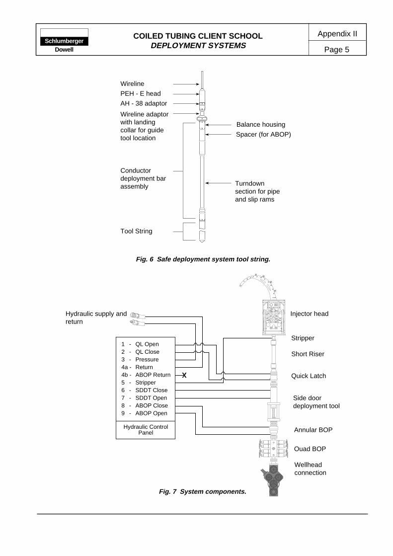
COILED TUBING CLIENT SCHOOLDEPLOYMENT SYSTEMS Page 5
Appendix IISchlumberger
Dowell
1 - QL Open2 - QL Close3 - Pressure4a - Return4b - ABOP Return5 - Stripper6 - SDDT Close7 - SDDT Open8 - ABOP Close9 - ABOP Open
Hydraulic ControlPanel
Fig. 7 System components.
Hydraulic supply andreturn
Ouad BOP
Wellheadconnection
Annular BOP
Short Riser
Injector head
Side doordeployment tool
Stripper
Quick Latch
Fig. 6 Safe deployment system tool string.
Wireline
Tool String
PEH - E head
AH - 38 adaptor
Wireline adaptorwith landingcollar for guidetool location
Conductordeployment barassembly
Balance housing
Turndownsection for pipeand slip rams
Spacer (for ABOP)
COILED TUBING CLIENT SCHOOLDEPLOYMENT SYSTEMS
Appendix II
Page 6Schlumberger
Dowell
Side Door Deployment Tool
Enables the toolstring to be connected after the injectorhead assembly has been connected and secured. Thisprovides several operational and safety benefits.
• CTU operator controls toolstring connection process.
• Injector head is grounded (electrically) beforetoolstring connections are made up.
Annular BOP
The annular BOP (ABOP) provides a contingencypressure containment function by sealing the annulargap around the tool sting or CT string as required(double barrier).
Hydraulic Control Panel
To ensure all operating functions can be completedfrom a position with clear line of sight, all safe deploymentsystems are controlled from a hydraulic control panel.The hydraulic connections (flow and return) to the panelis typically made through the auxiliary BOP hydraulicsupply on the CTU.
Downhole Equipment
The downhole equipment consists of a deployment barand a quick connect union system to enable easy andsafe make-up of the toolstring. A guide tool fitted in theSDDT enables positive indication that the deploymenttool is properly positioned across the BOP rams.
Additional Operating Requirements
The following operating requirements have beenidentified as key factors which may jeopardise thesafety or efficiency of the operation.
• Cranes must be certified as capable of operating atthe required height, reach and weight.
• Wellhead equipment should be inspected to ensurethat the additional weight and loading can be safelysupported and secured.
• Sufficient securing points should be available atground level.
• A work platform should be erected to enable easy/safe access to the SDDT.
3.1 Safe Deployment Sequence
The safe deployment sequence includes the followingbasic steps.
Note: this sequence is provided for information purposesonly and does not include all details of checks andprocedures necessary when designing a procedure.
a. Rig up equipment as shown in Figure 7
b. Assemble toolstring and install in wireline lubricator.Make up the QL connector to the lubricator.
c. Lift the lubricator on to the wellhead assembly andlatch the QL.
d. Equalise pressure to the lubricator, open the well-head valves and lower toolstring into wellbore untilthe tool locates in the SDDT guide (Figure 8).
e. Close BOP slip and pipe rams (and the ABOP) andvent the lubricator pressure.
f. Open the SDDT window and disconnect the runningtool and remove the lubricator assembly (Figure 9).
g. Fit upper QL connection to injector head assemblyand make up upper toolstring.
h. Lift the injector head assembly, latch QL, and secureguy wires/chains.
i. Open the SDDT window, run in with CT until toolstringconnection can be made up (Figure 10 and 11).
j. Close the SDDT and pressure test completed rig up(constrained by WHP below pipe rams/ABOP).
k. Equalise pressures and release pipe and slip rams,tag stripper to verify depth settings and proceed toRIH (Figure12).

COILED TUBING CLIENT SCHOOLDEPLOYMENT SYSTEMS Page 7
Appendix IISchlumberger
Dowell
Fig. 8 Installing the toolstring.
Fig. 9 Hanging off the toolstring.
Slip rams
Pipe rams
Blind rams
Tools run throughsystem to placedeployment bar withinBOP
Toolstring run/assembled usinglubricator andwireline deploymenttechnique
Ouad BOP
Wellheadconnection
Shear rams
Slip rams
Pipe rams
Blind rams
Running stringremoved fromdeployment bar
Lubricator removedat quick latch forsecond tool stage
Shear rams
SDDT
Annular BOP
Quick latch
Quad BOP
Wellheadconnection
SDDT
Annular BOP
Quick latch

COILED TUBING CLIENT SCHOOLDEPLOYMENT SYSTEMS
Appendix II
Page 8Schlumberger
Dowell
Fig. 10 Connecting the running string and toolstring.
Fig. 11 Guide tool and swivel connector.
Slip rams
Pipe rams
Blind rams
Second tool stage con-nected to deploymentbar
Injector head assemblyconnected to lowerpressure control stack
Wellheadconnection
Shear ramsAnnular BOP
Quick latch
Swivel connection toenable connection tobe made up withoutrotating assemblies
Guide tool toenable safe andeasy stabbing toconnections

COILED TUBING CLIENT SCHOOLDEPLOYMENT SYSTEMS Page 9
Appendix IISchlumberger
Dowell
Fig. 12 Running the toolstring.
Slip rams
Pipe rams
Blind rams
Window closed
Injector head assemblyconnected to lowerpressure control stac,window closed andassembly tested
Wellheadconnection
Shear rams
Annular BOP
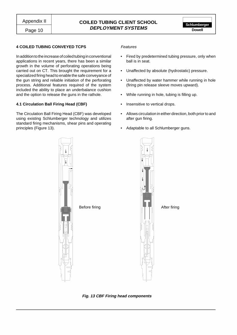
COILED TUBING CLIENT SCHOOLDEPLOYMENT SYSTEMS
Appendix II
Page 10Schlumberger
Dowell
4 COILED TUBING CONVEYED TCPS
In addition to the increase of coiled tubing in conventionalapplications in recent years, there has been a similargrowth in the volume of perforating operations beingcarried out on CT. This brought the requirement for aspecialized firing head to enable the safe conveyance ofthe gun string and reliable initiation of the perforatingprocess. Additional features required of the systemincluded the ability to place an underbalance cushionand the option to release the guns in the rathole.
4.1 Circulation Ball Firing Head (CBF)
The Circulation Ball Firing Head (CBF) was developedusing existing Schlumberger technology and utilizesstandard firing mechanisms, shear pins and operatingprinciples (Figure 13).
Features
• Fired by predetermined tubing pressure, only whenball is in seat.
• Unaffected by absolute (hydrostatic) pressure.
• Unaffected by water hammer while running in hole(firing pin release sleeve moves upward).
• While running in hole, tubing is filling up.
• Insensitive to vertical drops.
• Allows circulation in either direction, both prior to andafter gun firing.
• Adaptable to all Schlumberger guns.
Fig. 13 CBF Firing head components
After firingBefore firing
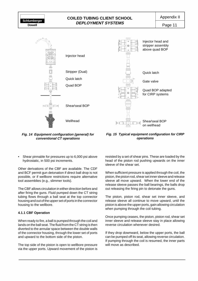
COILED TUBING CLIENT SCHOOLDEPLOYMENT SYSTEMS Page 11
Appendix IISchlumberger
Dowell
• Shear pinnable for pressures up to 6,000 psi abovehydrostatic, in 500 psi increments.
Other derivations of the CBF are available. The CDFand BCF permit gun detonation if direct ball drop is notpossible, or if wellbore restrictions require alternativetool assemblies (e.g., slimmer tools).
The CBF allows circulation in either direction before andafter firing the guns. Fluid pumped down the CT stringtubing flows through a ball seat at the top connectorhousing and out of the upper set of ports in the connectorhousing to the wellbore.
4.1.1 CBF Operation
When ready to fire, a ball is pumped through the coil andlands on the ball seat. The fluid from the CT string is thendiverted to the annular space between the double wallsof the connector housing, through the lower set of portsand upward to the bottom side of the piston.
The top side of the piston is open to wellbore pressurevia the upper ports. Upward movement of the piston is
resisted by a set of shear pins. These are loaded by thehead of the piston rod pushing upwards on the innersleeve of the shear set.
When sufficient pressure is applied through the coil, thepiston, the piston rod, shear set inner sleeve and releasesleeve all move upward. When the lower end of therelease sleeve passes the ball bearings, the balls dropout releasing the firing pin to detonate the guns.
The piston, piston rod, shear set inner sleeve, andrelease sleeve all continue to move upward, until thepiston is above the upper ports, gain allowing circulationwhen pumping through the coil tubing.
Once pumping ceases, the piston, piston rod, shear setinner sleeve and release sleeve stay in place allowingreverse circulation whenever desired.
If they drop downward, below the upper ports, the ballcan be pumped off its seat, allowing reverse circulation.If pumping through the coil is resumed, the inner partswill move as described.
Fig. 14 Equipment configuration (general) forconventional CT operations
Fig. 15 Typical equipment configuration for CIRPoperations
Stripper (Dual)
Wellhead
Shear\seal BOP
Quad BOP
Quick latch
Injector head
Gate valve
Shear\seal BOPon wellhead
Quad BOP adaptedfor CIRP systems
Quick latch
Injector head andstripper assemblyabove quad BOP

COILED TUBING CLIENT SCHOOLDEPLOYMENT SYSTEMS
Appendix II
Page 12Schlumberger
Dowell
4.2 CIRP Deployment System
The CIRP Deployment System (Completion Insertionand Retrieval of long gun strings under Pressure) isdesigned to allow the running and retrieval of long toolstrings, regardless of available lubricator. Connectionsare made inside the pressure control stack at wellborepressures utilizing the Safeconn connector system(Drexel).
Applications for this technology include the running ofperforating guns, logging tools, sand screens, coiledtubing drilling assemblies or any application where toolstring length exceeds available surface riser/lubricatorheight.
The special snaplock connector allows long gun stringsto be run and retrieved under pressure. Placed betweentwo guns, the tool allows the operator to connect anddisconnect the guns inside a specially modified BOPstack without direct access (Figure 14 and 15). On longgun strings several connectors may be used.
A sealed ballistic transfer is used on both sides of theconnection. Figure 16 shows the snaplock connector inthe disconnected and connected conditions.
The special BOP uses two modified rams to operate thesnaplock connector. Both rams have a secondary ramlocated within the primary ram mechanism that providesadditional functions (Figure 16).
The large lower ram serves as a no-go ram, closing toa diameter only slightly larger than the slick joint. It alsohas matching gear teeth that engage in the no-gogroove to prevent rotation of the lower portion of thesnaplock connector.
The large upper ram closes to a diameter just slightlylarger than the OD of the connector and serves as acentering guide. The smaller internal ram is equippedwith a rack that, when extended, engages the piniongear teeth located at the top of the breech lock sleeve ofthe connector. The rack thus turns the breech locksleeve to unlock and lock the connector.
Fig. 16 CIRP System components
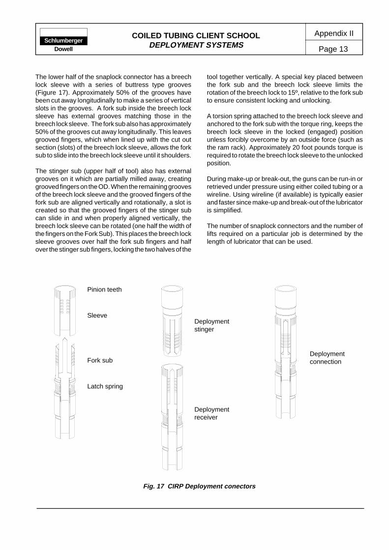
COILED TUBING CLIENT SCHOOLDEPLOYMENT SYSTEMS Page 13
Appendix IISchlumberger
Dowell
The lower half of the snaplock connector has a breechlock sleeve with a series of buttress type grooves(Figure 17). Approximately 50% of the grooves havebeen cut away longitudinally to make a series of verticalslots in the grooves. A fork sub inside the breech locksleeve has external grooves matching those in thebreech lock sleeve. The fork sub also has approximately50% of the grooves cut away longitudinally. This leavesgrooved fingers, which when lined up with the cut outsection (slots) of the breech lock sleeve, allows the forksub to slide into the breech lock sleeve until it shoulders.
The stinger sub (upper half of tool) also has externalgrooves on it which are partially milled away, creatinggrooved fingers on the OD. When the remaining groovesof the breech lock sleeve and the grooved fingers of thefork sub are aligned vertically and rotationally, a slot iscreated so that the grooved fingers of the stinger subcan slide in and when properly aligned vertically, thebreech lock sleeve can be rotated (one half the width ofthe fingers on the Fork Sub). This places the breech locksleeve grooves over half the fork sub fingers and halfover the stinger sub fingers, locking the two halves of the
tool together vertically. A special key placed betweenthe fork sub and the breech lock sleeve limits therotation of the breech lock to 15º, relative to the fork subto ensure consistent locking and unlocking.
A torsion spring attached to the breech lock sleeve andanchored to the fork sub with the torque ring, keeps thebreech lock sleeve in the locked (engaged) positionunless forcibly overcome by an outside force (such asthe ram rack). Approximately 20 foot pounds torque isrequired to rotate the breech lock sleeve to the unlockedposition.
During make-up or break-out, the guns can be run-in orretrieved under pressure using either coiled tubing or awireline. Using wireline (if available) is typically easierand faster since make-up and break-out of the lubricatoris simplified.
The number of snaplock connectors and the number oflifts required on a particular job is determined by thelength of lubricator that can be used.
Fig. 17 CIRP Deployment conectors
Sleeve
Latch spring
Fork sub
Pinion teeth
Deploymentstinger
Deploymentreceiver
Deploymentconnection

COILED TUBING CLIENT SCHOOLDEPLOYMENT SYSTEMS
Appendix II
Page 14Schlumberger
Dowell
Inner ram - OPENOuter Ram - OPEN
Inner ram - OPENOuter Ram - OPEN
Fig. 18 Run in to position the slick joint
Wireline conveyed toolstring
4.2.1 Operation
The following discussion is intended to provide basicunderstanding of the system and does not containsufficient information to enable job design or execution.
The BOP stack is made up on the wellhead with singleor double master valves between it and the lubricator(Figure 14 and 15). A special pick-up and lay-downassembly is typically required. This consists of a standardpick-up nipple, a short gun (for weight) and the top halfof a snaplock connector.
The top gun of a string is dressed with the lower half ofa snaplock connector. If more than one lift is to be made,the lower end of each subsequent lift will also require theupper half of a snaplock connector.
Although lengths may allow the firing head to be pickedup with the last lift, it is good practice to pick up the safetyspacer with the last gun lift and to make a special lift forthe firing head alone. This allows the firing head to beconnected with the guns safely below the BOP stack.
With the first lift (bottom of the gun string) made up onthe pick-up and lay-down assembly and inside thelubricator, the lubricator is made up on the wellhead asshown. The lubricator is then slowly pressurized toequal wellhead pressure. When the lubricator pressureequals the wellhead pressure, the master valve(s) areopened.
With the master valve(s) open, the first gun section islowered into the wellbore until the slick joint of thesnaplock connector is opposite the no-go rams (lowerset of rams) of the BOP stack (Figure 18).
At this time, the no-go rams are closed on the slick jointand the string slowly lowered until it stops. This shouldbe when the ram lock groove at the top of the slick jointreaches the ram (Figure 19). Note: the slick joint belowthe ram lock groove is smaller than the upset above thegroove.
The lock ram is then closed (Figure 20) to preventmovement in the lower section of the snaplock andlocking it against rotation. Next the guide rams (upperset of rams) are extended to centralize the upper end ofthe snaplock.
A pull test is performed to ensure that the snaplock issecured in the proper position within the BOP. The gunstring is then hung-off on the rams.
The robot arm (within the guide rams) is extended torotate the snaplock connectors breech lock sleeve tothe unlocked position. The upper half of the snaplockconnector is then slowly pulled out of the lower half withthe cable.

COILED TUBING CLIENT SCHOOLDEPLOYMENT SYSTEMS Page 15
Appendix IISchlumberger
Dowell
Inner ram - OPENOuter Ram - CLOSED
Inner ram - OPENOuter Ram - OPEN
Fig. 19 Close no go rams and set down tool weight
Inner ram - OPENOuter Ram - OPEN
Fig. 20 Close locks and perform pull test
Inner ram - CLOSEDOuter Ram - CLOSED

COILED TUBING CLIENT SCHOOLDEPLOYMENT SYSTEMS
Appendix II
Page 16Schlumberger
Dowell
Inner ram - CLOSEDOuter Ram - CLOSED
Inner ram - CLOSEDOuter Ram - CLOSED
Fig. 22 Run in with next tool string
Inner ram - CLOSEDOuter Ram - CLOSED
Inner ram - CLOSEDOuter Ram - CLOSED
Fig. 21 CIRP Close guide rams and engage rack to disconnect running tool
When the upper half of the snaplock connector is safelyin the lubricator (above the top of the BOP stack andvalves), the master valve(s) are closed (Figure 21).
With the master valve(s) closed, the pressure on thelubricator is slowly bled off and the lubricator removedready for the next lift.
With the second lift inside the lubricator, the lubricator isreconnected to the BOP stack and the internal pressureslowly brought up to equalize wellhead pressure. Whenthe pressure is equalized, the master valve(s) areopened and the second gun section is slowly lowered toengage the snaplock connector (Figure 22). The stingeron the bottom of the second lift enters the matingsnaplock section hung off on the no-go ram.

COILED TUBING CLIENT SCHOOLDEPLOYMENT SYSTEMS Page 17
Appendix IISchlumberger
Dowell
Inner ram - CLOSEDOuter Ram - CLOSED
Inner ram - OPENOuter Ram - CLOSED
Fig. 23 Stab male stinger, open rack and pull test connector
With the second gun section landed, the robot ram isretracted, engaging the breech lock between the stinger(attached to the bottom of the second lift) and the lowerhalf of the snaplock (attached to the top of the first lift).The cable is then raised, applying a pull to the connectionto ensure it is correctly engaged.
When it is confirmed that the snaplock connector isengaged, the overpull is decreased to equal the weightof the gun string and the guide rams, lock rams and no-
go rams are opened. The gun string is then lowered untilthe slick joint of the snaplock connector between the topof the second lift and the pick-up and lay-down assemblyis opposite the no-go ram.
At this time, the no-go rams are closed on the slick jointand the string slowly lowered until it stops. This shouldbe when the ram lock groove at the top of the slick jointreaches the ram. The lock ram is then closed, as before,to prevent movement of the lower BHA section.
Inner ram - OPENOuter Ram - OPEN
Inner ram - OPENOuter Ram - OPEN
Fig. 24 Open guide rams, locks and no-go rams and RIH

COILED TUBING CLIENT SCHOOLDEPLOYMENT SYSTEMS
Appendix II
Page 18Schlumberger
Dowell
The disconnection sequence as outlined above isrepeated.
The installation sequence is repeated on each gunsection as required to run the desired total length ofguns.
The safety spacer with a snaplock connector looking upis the second last section to be installed. After the safetyspacer lift is landed and locked in the no-go ram, thepick-up and lay-down assembly is laid down, the wirelinestuffing box is removed from the lubricator, and thelubricator attached to the coiled tubing stripper. A coiledtubing firing head such as the CBF with a snaplockconnector stinger on the bottom of the firing head isprepared and attached to the bottom of the coiled tubingas shown in (Figure 23).
The lubricator is attached to the BOP stack.
If it is necessary to pressure test the firing head it can besafely done at this time, while the firing head in thelubricator and not yet attached to the gun string. Aftertesting, the lubricator pressure is equalized with thewellhead pressure.
With the no-go ram open the string is then lowered in thewell (Figure 24).
4.3 Depth Correlation of Guns When Conveyed onCoil
When perforating with conventional TCP guns, a gammaray/CCL electric line lay is the normal practice prior tosetting the packer. The same technique is used whenelectric line perforating is performed on CT. However, inpurely hydraulic the operation is more complex.
The most common method uses a memory loggingstring. This involves performing an initial drift run withthe CT, which is the memory PL string. The correlationprocedure requires a careful and methodical approachin order to get it right without complications. Typically,two tool strings would be run to provide full back up onthe tool functions. The reference point on this type of jobis the coil tubing check valve. This is because the checkvalves are common to both BHAs.
The correlation procedure may be summarized asfollows:
• Perforation logs are taken from electric line logs.
• CBL/VDL/GR log will show the casing pip tag onSchlumberger depth.
• Five minute stations are done on the coil. Flags aremade on the coil at the top and bottom points.
• Coil depth at the top and bottom flags are noted.These depths are taken after moving in the updirection only.
• MPL tools are generally run through the zone ofinterest, and this should include some GRcharacteristics.
• If the zone is flat with its GR response, chooseanother nearby zone with some more activity.
• 300 ft is about the minimum logging interval and1,800 ft per hour is the ideal speed.
• The flagging procedure is repeated for a total of threeup passes at the same speed.
• Pull out of hole. Make a CCL time mark on eachmemory unit and record carefully.
• Rig down tools and read memory.
• Plot data corrected for time and depth.
• Logs can be corrected to match electric line log.
• When running TCP guns, run to bottom flag, andmove accordingly up or down to compensate fordepth error, locate, and fire.

Appendix III
Page 1COILED TUBING CLIENT SCHOOL MANUAL
COILED TUBING UNIT SIMULATOR
ContentsPageContents Page
SchlumbergerDowell
* Mark of Schlumberger
1 INTRODUCTION ......................................... 12 THE LEARNING PROCESS ........................ 1
1. INTRODUCTION
Controlled environment training (e.g., classroomtraining) of coiled tubing operators has historically beenrestricted to so called awareness and knowledge training.Acquiring operating skills was largely left to experienceon coiled tubing units in the field. However, in developingany skill, minor mistakes and mishaps are virtuallyunavoidable. Close supervision during the early stagesof on-the-job training has generally been an adequatemeans of ensuring the necessary levels of safety andreliability were maintained within the service.
As the equipment, techniques and applicationsassociated with CT services become more complex,higher demands are placed on the operator. In the highrisk environment of well site operations, theconsequences of even minor incidents can be severe.Consequently any means of accelerating progressaround the operator learning and skills curve isadvantageous.
With the availability of powerful computers and evermore realistic simulation environments, the concept ofa full sized coiled tubing unit simulator has beendeveloped and delivered. The system enables traineeoperators to acquire and practice basic skills within acontrolled classroom environment. Specific trainingprogrammes have been designed to expose trainees tooperating conditions that increase in complexity as theyadvance. Problem areas can be identified and ifnecessary specific focus can be maintained to meet theneeds of individual trainees. In such cases, the ability tomeasure or monitor progress is beneficial to theconfidence of both the instructor and the trainee.
The CTU simulator integrates a CTU console withelectronic hardware, specialized software, andadvanced sound and visual systems to provide asimulated environment encompassing the key features
of modern CT operations . Several contingency scenarioshave been programmed ensuring the trainee operatorgains familiarity with potentially dangerous situations,before exposure to the real world.
2. THE LEARNING PROCESS
Modern training is an integrated process utilizing avariety of media and technical aids to convey awarenessand knowledge to trainees. In ascending their careerpath, trainees/operators are typically exposed to asequence of new job functions or techniques requiringfurther development of awareness, knowledge and skills.Such a career path can be illustrated as a series of ‘S’shape curves.
It has been established (notably within the aerospaceindustries) that the introduction of training simulatorssignificantly reduces the time required to achievenecessary competency levels (Figure 1 and 2). In additionthis is achieved in the relative safety of the classroom,without exposing the trainee to dangers of the well site.Similarly, clients can be assured that risks associatedwith operator in-experience are minimized.
2.1 Interactive Training
While the simulator expedites familiarisation with fieldoperations it is essential that trainees follow the sameequipment configuration and set up procedures as in“real life”. Ensuring the trainee uses the same analyticalpath for set up options reinforces the importance of acomprehensive training syllabus which then must becomesecond nature for field operations. For example, a varietyof components and configuration options are providedfor selection, so the trainee has to give due regard toposition and performance of the individual items as wellas their interaction with the assembled system.
2.1 Interactive Training ............................ 32.2 Coiled Tubing Operations .................. 3

COILED TUBING CLIENT SCHOOLCOILED TUBING UNIT SIMULATOR
Appendix III
Page 2Schlumberger
Dowell
Introductory course commences
Second course commencesField
experience
Fieldexperience Third course
TIME
LEA
RN
ING
Figure. 1 The learning curves
Class Field
FieldClass
On the jobtraining
Knowledge(School)
Awareness(Pre-school)
TIME
TR
AIN
ING
Figure. 2 Simulator assisted learning curve

COILED TUBING CLIENT SCHOOLCOILED TUBING UNIT SIMULATOR Page 3
Appendix IIISchlumberger
Dowell
Another important benefit of simulator training relates torecognition of self-advancement during the course,particularly when career limiting competency basedassessment is taking place. The simulator provides realtime hard-copy outputs of the key operational parameters(such as pressures, weight, depth etc.) which can beused over several sessions to monitor progress.
Trainee enjoyment is a secondary factor which also hasimportant benefits. After long periods of theory, simulatorexercises are often viewed as the highlight of a trainingprogramme. Learning value is more concentrated andthe simulator is often preferred to lecturing.
The simulator was designed and manufactured to reflecttypical CTU control panels (Figure 3). The simulatorconsoles incorporated original levers and valves toretain the required look and feel. For example; hydrauliccontrol actuators were adapted to receive electronicmicro switches giving the correct feel when operatingthe valve handles. This resemblance to originality notonly serves for rapid visual recognition by the trainee butresults in the exercise being treated seriously by eventhe most sceptical students.
The ability to stage malfunctions or contingencies duringthe course of an exercise provides the greatest benefitto simulator training. Here the instructor can readily testreaction times and the thought sequence of the trainee.Malfunctions programmed into the simulator includedequipment failures, tubing run-away, hydraulic failures,circulation leaks, tight hole and choke malfunctions.
2.2 Coiled Tubing Operations
Training programmes can be structured with differentthemes depending on the classification of the trainee.For example, two categories are immediately apparent.The first relates to training programmes for coiled tubingoperators and field service supervisors with directresponsibility for setting up and operating the CTequipment. The second category includes field engineerswho are generally responsible for designing andsupervising the overall operation which may includeadditional equipment and systems associated with theCTU.
Simulator exercises are similar for both groups and aretypically contained in one of four categories:
• Setting up the unit
• Executing the job as designed
• Emergency response simulation
• Pressure control exercises
A fundamental requirement of operators is that they cancorrectly “sweep” or “scan” the unit instrumentation.Primary hydraulic system gauges require more frequentscanning than secondary or supporting systems, whilethe weight indicator, wellhead pressure and circulatingpressure gauges require almost constant monitoring.This basic operator skill is a prerequisite to successfullycompleting the initial simulator practical assessment.
Job execution training requires the trainee to completea list of job instructions such as would be required toundertake a specific operation, e.g., wellbore fill removal,logging or well kick-off. Such training and assessmentfocuses on the operation of the key coiled tubing unitcomponents, e.g., injector head control, applied reelback tension, stripper control, operation of the level-wind and understanding the power pack and hydraulicsystems.
When the trainee has gained familiarity with the generalcontrols, a variety of operating conditions or malfunctionscan be introduced into the simulation exercise(Figure 4). These are categorised in four main equipmentor operational areas:
• CT string malfunction - pin-hole, parted string
• Equipment failures - power pack, prime mover, 30gpm pump etc
• Downhole problems - tight hole, lockup, wellbore fill
• Pressure Control - gas influx, choke washout, pumpfailure
It is the experience of applying the methodology inresponse to these conditions that is one of the keybenefits of a training simulator. Although much of thesimulator training could be performed on a conventionalcoiled tubing unit and test well set-up, the critical aspectsof problem recognition and learning a trained responsewould be difficult if not impossible in a comparable timeframe.

COILED TUBING CLIENT SCHOOLCOILED TUBING UNIT SIMULATOR
Appendix III
Page 4Schlumberger
Dowell
In addition, it is only within the controlled environment ofa classroom that the instructor can accurately andconsistently assess competence on repeatable unbiasedbasis. Trainees who are likely to become excessivelystressed under emergency conditions are readilyidentified and can be offered additional coaching.
Although the CTU simulator provides a reliable basis fortraining and assessing skills, it is only one part of acomprehensive competency based training programmefor Dowell CTU personnel.
Figure. 3 Dowell CTU simulator - UTC 1997
Figure. 4 CTU simulator - training exercise in progress