coker valves interlock improvement project at suncor ... · coker valves interlock improvement...
TRANSCRIPT

Coker Valves Interlock Improvement Project at Suncor Energy Inc.
Dom Toledo – E&I Reliability Engineering Manager – Upgrading Plant, Oil Sands Fort McMurray AB, Canada
1

•Upgrader II (U2) coke drums utilizes motor operated valves to operate coke drum valves during the various coking cycle operation. These coker valves are interlocked to coke drum pressure and temperature including valve position of appropriate cokervalves.•Relevant incident on Oct. 2007, one of coke drum had a fire from opening the ejector valve while the drum is being charged. Est. production loss $ 30 M.•In another incident, two coker operators were removing top head of coke drum when steam released occurred. One operator received second degree burns.•On Jan. 2011 from another Oil Sands operator, the wrong coker valve was openedcausing massive fire to their coker. Est. damage and losses $ 500 M including 3injured personnel.
Objective•Eliminate potential loss of containment from valve misalignment or operating incorrect valve during coker valves operation. •Implementation of coker valve interlocks and permissives that will prevent from opening a hot drum during the various coking cycle.•Implementation of DCU PHA / LOPA recommendations which require additional permissive during coker valve operation.•Monitoring and trending of coker valve position and torque feedback for valve deterioration.
Background
2

Upgrading coke drums with coker valves
3

Coker drum set with original coker valves interlock setup
4

Existing setup
• Inadequate interlocks on coker switch valve, charge, ejector and drain valves due to limited capability of current interlock system using electro-mechanical relays in the switch valve panel.
• Limited interlock as only the first or inside valve on the ejector and drain valves are available. There is no interlock on the outside or second valve.
• There are no valve interlocks to blowdown, warm up, vapour and steam out valves potentially causing misalignment or incorrect valve operation.
• Temporary jumper wires are installed in the relay switch panel when coker valve does not reach limit switch. This will require electrician to install and monitor jumper wire status after each coking cycle.
5

Original electro-mechanical relay panel
6

Solution
• Install PLC for coker valve interlock system for all 6 coker drums. Control logic can be programmed for more robust interlock setup.
• Install local HMI in the coker switch deck for monitoring valve interlock status and valve torque & position. Capability for trending of valve torque for monitoring valve deterioration or degradation.
• Provide additional valve interlock to other coker valves as per PHA / LOPA recommendations.
• Provide DCS bypass for each valve interlock which is traceable, monitored and audited.
7

Coker valve interlock PLC panel
8
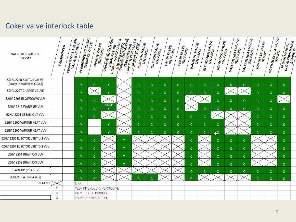
Coker valve interlock table
9

System Architecture for coker interlock project
10

Interconnection diagram for one set of coke drum
11

MOV Actuator schematic diagram modification for valve position & torque
12

Pop up screen for valve position feedback and torque
13

HMI Display for one set of coke drum
14

Wonderware HMI Panel – Coker valve interlock
15

Benefits from PLC based interlock
• Display coker valves status i.e. valve position and torque
• Coker valves permissive status are readily available on DCS & HMI
• Increased coker operator productivity due to ease of troubleshooting
• Interlock bypasses are monitored and audited on a daily basis
• Modification of interlock or permissive can be easily implemented on PLC
Project execution
• Project implementation by Maintenance and Reliability engineering team due to urgency of requirement and cost efficiency.
• Project engineer and maintenance coordinator were assigned to ensure planning and execution by contractors are well coordinated.
• Length of Cables Pulled – 15000 Feet
• 1700 Engineering man-hours
• 7000 man-hours electrical & instrumentation contractors
16

Conclusion
• Selection of the Triconex Tri GP PLC was the right choice for this project for the following reason:
1. High degree of reliability with the triple redundant processor from Triconex up to SIL-2 rated PLC.
2. Ease of maintenance and programming as the Tristation software is common throughout the plantsite. Minimal training required to our maintenance and control systems personnel.
3. Fully integrated remote communication to our Honeywell TDC 3000 DCS and Tri-GP’s serial communication module.
4. Medium size no. of I/O’s which is suitable for this type of project.
5. Compact footprint of PLC panel due to space constraints.
• Right balance between system reliability and cost.
17
DOM TOLEDO, P.Eng
E&I RELIABILITY ENGINEERING MANAGER – PRIMARY UPGRADING
SUNCOR ENERGY INC. - OIL SANDS
Phone no: 780 7436719
18