cold-formed steel bolted connections without washers on
TRANSCRIPT

Cold-Formed Steel Bolted Connections Without Washers on Oversized and Slotted Holes Phase 1
R E S E A R C H R E P O R T R P 0 8 - 1 1 J U L Y 2 0 0 8
Committee on Specif ications
for the Design of Cold-Formed
Steel Structural Members
re
sear
ch re
port
American Iron and Steel Institute
The material contained herein has been developed by researchers based on their research findings. The material has also been reviewed by the American Iron and Steel Institute Committee on Specifications for the Design of Cold-Formed Steel Structural Members. The Committee acknowledges and is grateful for the contributions of such researchers.
The material herein is for general information only. The information in it should not be used without first securing competent advice with respect to its suitability for any given application. The publication of the information is not intended as a representation or warranty on the part of the American Iron and Steel Institute, or of any other person named herein, that the information is suitable for any general or particular use or of freedom from infringement of any patent or patents. Anyone making use of the information assumes all liability arising from such use.
Published 2010
Copyright 2010 American Iron and Steel Institute
Cold-Formed Steel Bolted Connections
Without Washers on Oversized and Slotted Holes
Phase 1 Report
Submitted to
The American Iron and Steel Institute
by
Cheng Yu Assistant Professor
Ibraheem Sheerah
Graduate Research Assistant
July 23, 2008
Department of Engineering Technology University of North Texas
Denton, Texas 76207
i
TABLE OF CONTENTS
1 ABSTRACT 1
2 INTRODUCTION 2
3 BACKGROUND 3
4 RESEARCH OBJECTIVES AND PLAN 4 4.1 PHASE 1 RESEARCH OBJECTIVES ............................................................................................... 4 4.2 PHASE 2 RESEARCH OBJECTIVES ............................................................................................... 4 4.3 WORK PLAN AND DELIVERABLES ................................................................................................ 5
5 LITERATURE REVIEW 6 5.1 SHEET SHEAR STRENGTH METHOD ............................................................................................ 6 5.2 BEARING STRENGTH METHOD ...................................................................................................... 6
6 TEST SETUP 9 6.1 TESTING EQUIPMENTS AND METHOD FOR CONNECTION TESTS .......................................... 9 6.2 COUPON TESTS FOR MATERIAL PROPERTIES ......................................................................... 10
7 TEST SPECIMENS 11 7.1 SPECIMEN CONFIGURATIONS ...................................................................................................... 11 7.2 SPECIMEN LABELING ..................................................................................................................... 16 7.3 TEST MATRIX FOR PHASE 1 – BEARING AND SHEAR FAILURE OF THE SHEETS .............. 16 7.4 TEST MATRIX FOR PHASE 2 – FRACTURE FAILURE OF THE SHEETS .................................. 19
8 TEST RESULTS 22 8.1 COUPON TESTS FOR MATERIAL PROPERTIES ......................................................................... 22 8.2 TENSILE TESTS ON BOLTED CONNECTIONS WITHOUT WASHERS ON OVERSIZED HOLES
(MAIN GROUP) ................................................................................................................................... 24 8.3 TENSILE TESTS ON BOLTED CONNECTIONS WITHOUT WASHIERS ON OVERSIZED HOLES
(ADDITIONAL GROUP) ...................................................................................................................... 38 8.4 TENSILE TESTS ON BOLTED CONNECTIONS WITHOUT WASHIERS ON SHORT SLOTTED
HOLES ................................................................................................................................................. 41
9 DISCUSSION 56 9.1 SHEET BEARING STRENGTH OF BOLTED CONNECTIONS WITHOUT WASHERS ON
OVERSIZED HOLES ........................................................................................................................... 56 9.2 SHEET SHEAR STRENGTH OF BOLTED CONNECTIONS WITHOUT WASHERS ON
OVERSIZED HOLES ........................................................................................................................... 61 9.3 LOW DUCTILE VS HIGH DUCTILE STEEL .................................................................................... 63 9.4 A307 VS A325 BOLTS ...................................................................................................................... 64 9.5 CONNECTIONS WITH DIFFERENT SHEETS AND DIFFERENT HOLE SIZES ........................... 68
ii
9.6 TWO-BOLT CONNECTIONS WITH OVERSIZED HOLES IN BEARING AND SHEAR COMBINED FAILURE .............................................................................................................................................. 69
9.7 OPTIONS OF WASHERS AND HOLE SIZES (ADDITIONAL GROUP) ........................................ 70 9.8 SHEET BEARING STRENGTH OF BOLTED CONNECTIONS WITHOUT WASHERS ON
SLOTTED HOLES ............................................................................................................................... 74 9.9 SHEET SHEAR STRENGTH OF BOLTED CONNECTIONS WITHOUT WASHERS ON SLOTTED
HOLES ................................................................................................................................................. 76 9.10 TWO-BOLT CONNECTIONS WITH SLOTTED HOLES IN BEARING AND SHEAR COMBINED
FAILURE .............................................................................................................................................. 77
10 PRELIMINARY CONCLUSIONS 78
11 CONTINUING RESEARCH 79
12 ACKNOWLEDGEMENT 79
13 REFERENCES 80
iii
LIST OF FIGURES
FIG 2-1 TYPICAL FAILURES OF BOLTED COLD-FORMED STEEL CONNECTIONS 2
FIG 4-1 PRELIMINARY WORK PLAN 5
FIG 6-1 SETUP FOR TENSILE TESTS ON BOLTED CONNECTIONS 9
FIG 6-2 TOP AND BOTTOM GRIPS 10
FIG 7-1 - RECOMMENDED TEST DIMENSIONS FOR STRUCTURAL BOLTS (ZADANFARROKH AND BRYAN, 1992) 12
FIG 7-2 DIMENSIONS OF SPECIMENS WITH ONE BOLT FOR PHASE 1 13
FIG 7-3 DIMENSIONS OF SPECIMENS WITH TWO BOLTS FOR PHASE 1 14
FIG 7-4 DIMENSIONS OF SPECIMENS WITH ONE BOLT FOR PHASE 2 15
FIG 7-5 DIMENSIONS OF SPECIMENS WITH TWO BOLTS FOR PHASE 2 15
FIG 8-1 STRESS – STRAIN CURVES FOR TESTED MATERIALS 23
FIG 8-2 SHEET BEARING FAILURE OF SINGLE SHEAR CONNECTION OH-43O-43O-A307-1/2-1-SS-4-T1 24
FIG 8-3 SHEET BEARING FAILURE OF DOUBLE SHEAR CONNECTION OH-43O-43O-A307-1/2-1-DS-4-T1 24
FIG 8-4 LOAD VS DEFORMATION CURVES FOR BEARING STRENGTH TESTS WITH ONE BOLT 25
FIG 8-5 SHEET BEARING FAILURE OF SINGLE SHEAR CONNECTION OH-43O-43O-A307-1/2-2-SS-4-T1 26
FIG 8-6 SHEET BEARING FAILURE OF DOUBLE SHEAR CONNECTION OH-43O-43O-A307-1/2-2-DS-4-T1 26
FIG 8-7 LOAD VS DEFORMATION CURVES FOR BEARING STRENGTH TESTS WITH TWO BOLTS 27
FIG 8-8 SHEET SHEAR FAILURE OF SINGLE SHEAR CONNECTION OH-33O-33O-A307-1/2-1-SS-1.5-T2 32
FIG 8-9 SHEET SHEAR FAILURE OF DOUBLE SHEAR CONNECTION OH-33O-33O-A307-1/2-1-DS-1.5-T1 33
FIG 8-10 LOAD VS. DEFORMATION CURVES FOR SHEET SHEAR STRENGTH TESTS 33
FIG 8-11 FAILURE MODE OF TEST OH-33O-33O-A307-1/2-2-SS-1.5-T1 36
FIG 8-12 FAILURE MODE OF TEST OH-33O-33O-A307-1/2-2-DS-1.5-T1 36
FIG 8-13 FAILURE MODE OF TEST WW-SH-43S-43S-A307-1/2-1-SS-4-T2 40
FIG 8-14 FAILURE MODE OF TEST WW-OH-43O-43O-A307-1/2-1-SS-4-T1 40
FIG 8-15 FAILURE MODE OF TEST SH-33S-33S-A307-1/2-1-SS-4-T3 40
iv
FIG 8-16 LOAD VS. DEFORMATION CURVES FOR SINGLE SHEAR CONNECTIONS WITH SINGLE BOLT, SLOTTED HOLES IN BEARING, 42
FIG 8-17 FAILURE MODE OF TEST SS-68-68-A307-9/16X3/4-1-SS-4-T2 42
FIG 8-18 FAILURE MODE OF TEST SS-68-68-A307-9/16X7/8-1-SS-4-T2 42
FIG 8-19 FAILURE MODE OF TEST SS-118-118-A307-9/16X3/4-1-SS-4-T2 43
FIG 8-20 FAILURE MODE OF TEST SS-118-118-A307-9/16X7/8-1-SS-4-T2 43
FIG 8-21 FAILURE MODE OF TEST SS-118-118-A307-9/16X3/4-2-SS-4-T2 43
FIG 8-22 FAILURE MODE OF TEST SS-118-118-A307-9/16X7/8-2-SS-4-T1 44
FIG 8-23 FAILURE MODE OF TEST SS-118-68-A307-9/16X7/8-1-SS-4-T2 44
FIG 8-24 FAILURE MODE OF TEST SS-118-68-A307-9/16X7/8-2-SS-4-T1 44
FIG 8-25 LOAD VS. DEFORMATION CURVES FOR SINGLE SHEAR CONNECTIONS WITH SINGLE BOLT, SLOTTED HOLES IN BEARING, 46
FIG 8-26 FAILURE MODE OF TEST SS-68-68-A307-9/16X3/4-1-DS-4-T2 47
FIG 8-27 FAILURE MODE OF TEST SS-68-68-A307-9/16X7/8-1-DS-4-T1 47
FIG 8-28 FAILURE MODE OF TEST SS-118-118-A307-9/16X3/4-1-DS-4-T2 47
FIG 8-29 FAILURE MODE OF TEST SS-118-118-A307-9/16X7/8-1-DS-4-T1 47
FIG 8-30 LOAD VS. DEFORMATION CURVES FOR SINGLE SHEAR CONNECTIONS WITH SINGLE BOLT, SLOTTED HOLES, IN SHEAR 49
FIG 8-31 FAILURE MODE OF TEST SS-118-118-A307-9/16X3/4-1-SS-1.5-T1 50
FIG 8-32 FAILURE MODE OF TEST SS-118-118-A307-9/16X7/8-1-SS-1.5-T1 50
FIG 8-33 FAILURE MODE OF TEST SS-68-68-A307-9/16X7/8-1-SS-1.5-T1 50
FIG 8-34 LOAD VS. DEFORMATION CURVES FOR DOUBLE SHEAR CONNECTIONS WITH SINGLE BOLT, SLOTTED HOLES, IN SHEAR 51
FIG 8-35 FAILURE MODE OF TEST SS-118-118-A307-9/16X3/4-1-DS-1.5-T1 52
FIG 8-36 FAILURE MODE OF TEST SS-118-118-A307-9/16X7/8-1-DS-1.5-T1 52
FIG 8-37 FAILURE MODE OF TEST SS-68-68-A307-9/16X3/4-1-DS-1.5-T1 52
FIG 8-38 FAILURE MODE OF TEST SS-68-68-A307-9/16X7/8-1-DS-1.5-T1 52
FIG 8-39 FAILURE MODE OF TEST SS-68-68-A307-9/16X3/4-2-SS-1.5-T3 54
FIG 8-40 FAILURE MODE OF TEST SS-68-68-A307-9/16X7/8-2-SS-1.5-T1 54
FIG 9-1 C VS D/T FOR BEARING STRENGTH TEST ON SINGLE SHEAR CONNECTIONS WITH OVERSIZED HOLES 56
FIG 9-2 C VS D/T FOR BEARING STRENGTH TEST ON DOUBLE SHEAR CONNECTIONS WITH OVERSIZED HOLES 57
FIG 9-3 TEST RESULTS VS. DESIGN METHODS FOR SINGLE SHEAR CONNECTIONS WITH OVERSIZED HOLES 60
v
FIG 9-4 TEST RESULTS VS. DESIGN METHODS FOR DOUBLE SHEAR CONNECTIONS WITH OVERSIZED HOLES 60
FIG 9-5 PTEST/PNAS VS D/T FOR SHEET SHEAR STRENGTH OF CONNECTIONS WITH OVERSIZED HOLES 62
FIG 9-6 43 MIL HIGH DUCTILE STEEL BEARING FAILURE 64
FIG 9-7 39 MIL LOW DUCTILE STEEL BEARING FAILURE 64
FIG 9-8 BEARING FAILURE OF A 68 MIL SINGLE SHEAR CONNECTION WITH ONE A307 BOLT 66
FIG 9-9 BEARING FAILURE OF A 68 MIL SINGLE SHEAR CONNECTION WITH ONE A325 BOLT 66
FIG 9-10 SHEET SHEAR FAILURE OF A 68 MIL SINGLE SHEAR CONNECTION WITH ONE A307 BOLT 67
FIG 9-11 SHEET SHEAR FAILURE OF A 68 MIL SINGLE SHEAR CONNECTION WITH ONE A325 BOLT 67
FIG 9-12 BEARING FACTOR C FOR SINGLE SHEAR AND OUTSIDE SHEETS OF DOUBLE SHEAR BOLTED CONNECTIONS [WITH WASHERS] (WALLACE, LABOUBE, SCHUSTER, 2001) 72
FIG 9-13 BEARING FACTOR C FOR SINGLE SHEAR AND OUTSIDE SHEETS OF DOUBLE SHEAR BOLTED CONNECTIONS [WITHOUT WASHERS] (WALLACE, LABOUBE, SCHUSTER, 2001) 73
FIG 9-14 TEST RESULTS VS. DESIGN METHODS FOR SINGLE SHEAR CONNECTIONS IN BEARING 74
FIG 9-15 TEST RESULTS VS. DESIGN METHODS FOR DOUBLE SHEAR CONNECTIONS IN BEARING 75
FIG 9-16 TEST RESULTS VS. DESIGN METHODS FOR DOUBLE SHEAR CONNECTIONS IN SHEAR 76
vi
LIST OF TABLES
TABLE 5-1 BEARING FACTOR C, FOR BOLTED CONNECTIONS WITHOUT WASHERS (WATERLOO METHOD) 7
TABLE 5-2 BEARING FACTOR C, FOR BOLTED CONNECTIONS (NAS, 2007) 8
TABLE 7-1 DIMENSIONS OF OVERSIZE HOLES AND SHORT SLOTS FOR BOTH PHASES OF TESTS 11
TABLE 7-2 TEST MATRIX FOR CONNECTIONS WITH OVERSIZE HOLES FOR PHASE 1 17
TABLE 7-3 TEST MATRIX FOR CONNECTIONS WITH SHORT SLOTS (9/16” × 3/4”) FOR PHASE 1 18
TABLE 7-4 TEST MATRIX FOR CONNECTIONS WITH SHORT SLOTS (9/16” × 7/8”) FOR PHASE 1 18
TABLE 7-5 TEST MATRIX FOR CONNECTIONS WITH SHORT SLOTS (9/16” × 3/4”) FOR PHASE 2 19
TABLE 7-6 TEST MATRIX FOR CONNECTIONS WITH OVERSIZED HOLES FOR PHASE 2 20
TABLE 7-7 TEST MATRIX FOR CONNECTIONS WITH SHORT SLOTS (9/16” × 7/8”) FOR PHASE 2 21
TABLE 8-1 MATERIAL PROPERTIES 22
TABLE 8-2 TEST RESULTS FOR SINGLE SHEAR CONNECTIONS WITH OVERSIZED HOLE, SINGLE BOLT, E/D >1.5 28
TABLE 8-3 TEST RESULTS FOR SINGLE SHEAR CONNECTIONS WITH OVERSIZED HOLE, DOUBLE BOLTS, E/D >1.5 29
TABLE 8-4 TEST RESULTS FOR DOUBLE SHEAR CONNECTIONS WITH OVERSIZED HOLE, SINGLE BOLT, E/D >1.5 30
TABLE 8-5 TEST RESULTS FOR DOUBLE SHEAR CONNECTIONS WITH OVERSIZED HOLE, DOUBLE BOLTS, E/D >1.5 31
TABLE 8-6 TEST RESULTS FOR SINGLE SHEAR CONNECTIONS WITH OVERSIZED HOLE, SINGLE BOLT, E/D =1.5 34
TABLE 8-7 TEST RESULTS FOR DOUBLE SHEAR CONNECTIONS WITH OVERSIZED HOLE, SINGLE BOLT, E/D =1.5 35
TABLE 8-8 TEST RESULTS FOR SINGLE SHEAR CONNECTIONS WITH OVERSIZED HOLE, DOUBLE BOLTS, E/D =1.5 37
TABLE 8-9 TEST RESULTS FOR DOUBLE SHEAR CONNECTIONS WITH OVERSIZED HOLE, DOUBLE BOLTS, E/D =1.5 37
TABLE 8-10 ADDITIONAL TESTS ON 33 MIL AND 43 MIL SINGLE SHEAR CONNECTIONS 39

vii
TABLE 8-11 TEST RESULTS FOR SINGLE SHEAR CONNECTIONS WITH SLOTTED HOLES, SINGLE BOLT, E/D =4 45
TABLE 8-12 TEST RESULTS FOR SINGLE SHEAR CONNECTIONS WITH SLOTTED HOLES, DOUBLE BOLTS, E/D =4 45
TABLE 8-13 TEST RESULTS FOR DOUBLE SHEAR CONNECTIONS WITH SLOTTED HOLES, SINGLE BOLT, E/D =4 48
TABLE 8-14 TEST RESULTS FOR DOUBLE SHEAR CONNECTIONS WITH SLOTTED HOLES, DOUBLE BOLTS, E/D =4 48
TABLE 8-15 TEST RESULTS FOR SINGLE SHEAR CONNECTIONS WITH SLOTTED HOLES, SINGLE BOLT, E/D =1.5 53
TABLE 8-16 TEST RESULTS FOR DOUBLE SHEAR CONNECTIONS WITH SLOTTED HOLES, SINGLE BOLT, E/D =1.5 53
TABLE 8-17 TEST RESULTS FOR SINGLE SHEAR CONNECTIONS WITH SLOTTED HOLES, DOUBLE BOLTS, E/D =1.5 55
TABLE 9-1 TEST-TO-PREDICTED RATIOS FOR SHEET BEARING STRENGTH OF SINGLE SHEAR CONNECTIONS WITH OVERSIZED HOLES 58
TABLE 9-2 TEST-TO-PREDICTED RATIOS FOR SHEET BEARING STRENGTH OF DOUBLE SHEAR CONNECTIONS WITH OVERSIZED HOLES 58
TABLE 9-3 PROPOSED BEARING FACTOR, C, FOR BOLTED CONNECTIONS WITH OVERSIZED HOLES 59
TABLE 9-4 PROPOSED MODIFICATION FACTOR, MF, FOR BOLTED CONNECTIONS WITH OVERSIZED HOLES 59
TABLE 9-5 RESISTANCE FACTORS AND FACTORS OF SAFETY FOR BOLTED CONNECTIONS IN BEARING 61
TABLE 9-6 TEST-TO-PREDICTED RATIOS FOR SHEET SHEAR STRENGTH OF CONNECTIONS WITH OVERSIZED HOLES 62
TABLE 9-7 COMPARISON IN BEARING STRENGTH BETWEEN A307 & A325 BOLTS 65
TABLE 9-8 COMPARISON BETWEEN 1/2” DIA. A307 AND A325 BOLTS IN SINGLE SHEAR 66
TABLE 9-9 COMPARISON AMONG FOR 33 MIL SINGLE SHEAR CONNECTIONS USING ONE 1/2” DIA. A307 BOLT 68
TABLE 9-10 COMPARISON BETWEEN COMBINED FAILURE AND TYPICAL FAILURES FOR SINGLE SHEAR 69
TABLE 9-11 COMPARISON BETWEEN COMBINED FAILURE AND TYPICAL FAILURES FOR DOUBLE SHEAR 70
TABLE 9-12 DIRECT COMPARISON BETWEEN TESTS ON CONNECTIONS WITH OVERSIZED HOLES AND STANDARD HOLES IN BEARING 71
viii
TABLE 9-13 COMPARISON BETWEEN COMBINED FAILURE AND TYPICAL FAILURES FOR SINGLE SHEAR CONNECTIONS 77
1
1 ABSTRACT
In cold-formed steel construction, bolted connections without washers for either
oversized or short slotted holes may significantly expedite the building process and
lower the cost. However, the current design specification does not include provisions for
such connections, and washers are required to be installed for oversized holes or short
slotted holes. The research presented in this report aims to experimentally investigate
three typical failure modes in cold-formed steel bolted connections with the non-washer
and oversized configurations. The three failure modes have been observed: sheet shear
failure, sheet bearing failure, and fracture failure of the net section in the connected
sheet. The research project consists of two phases. In Phase 1 the sheet shear and
bearing failures will be studied, and in Phase 2 the fracture failure will be investigated.
The test matrices include a full range of connection configurations covering various
steel sheet thicknesses from 30 mil to 118 mil, different connection types of single and
double shear using ASTM A307 and A325 bolt types, and high and low ductile steels.
2
2 INTRODUCTION
The cold-formed steel becomes an important alternative construction material for low-
rise residential and commercial buildings. Light weight, high durability, high strength,
and high material consistency are some of the reasons given for the increasing
application of cold-formed steel structures in construction. The bolted connection is one
of the common joining methods in cold-formed steel structures and it has been
experimentally studied by a number of researchers. However, the bolted connections in
oversized and short slotted holes without washers have not been fully studied yet, and
that is the focus of this research effort.
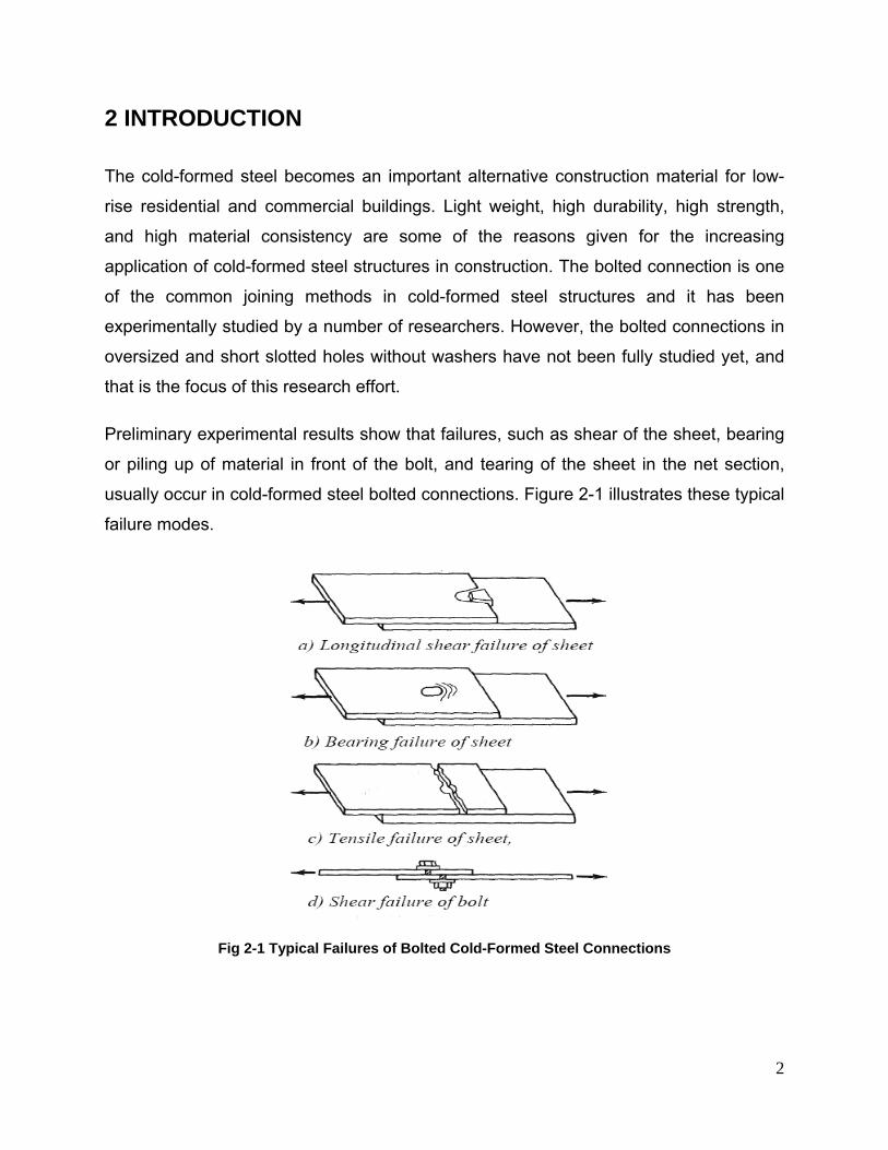
Preliminary experimental results show that failures, such as shear of the sheet, bearing
or piling up of material in front of the bolt, and tearing of the sheet in the net section,
usually occur in cold-formed steel bolted connections. Figure 2-1 illustrates these typical
failure modes.
Fig 2-1 Typical Failures of Bolted Cold-Formed Steel Connections
3
3 BACKGROUND
The bolted connections in cold-formed steel may fail in four types of failure: Type I
Shear of the sheet; Type II Bearing of the sheet, Type III Fracture in the net section of
the sheet, Type IV Shear in the bolt, as shown in Figure 1.
The current North American Specification for the Design of Cold-Formed Steel
Structural Members (NAS 2007) provides design provisions for those four types of
failure respectively. NAS (2007) also stipulates the dimensions of the perforations,
either holes or short slots, and the use of washers. The hole dimensions together with
the use of washers may significantly influence the first three types of failure. The NAS
(2007) requires that “washers or backup plates should be used over oversized or short-
slotted holes in an outer ply unless suitable performance is demonstrated by tests.”
This research project investigates the three failure modes of the cold-formed steel
bolted connections without washers on oversized and short slotted holes.
The experimental study will be divided into two phases. In Phase 1, the shear and the
bearing failures of the sheets will be investigated. In Phase 2, the fracture failure of the
net section of the sheets will be studied. The suggested test matrices are designed to
include a wide range of connection configurations including: (1) the sheet thickness
varying from 30 mil to 118 mil; (2) the connection type – single and double shear; (3) the
number of bolts – single and double bolts; (4) the bolt type – ASTM 307 (2007) and
ASTM 325 (2007); (5) the material ductility in sheets - low and high; (6) the diameter of
the bolt – ¼”, ½”, 5/8”.
Ultimately, the test results will be compared to the current NAS design provisions for
connections with non-washer and standard holes. New design provisions will be
developed to account for the configurations combining non-washers and oversized
oversized/short slotted holes.
4
4 RESEARCH OBJECTIVES AND PLAN
The main research objectives are to experimentally investigate the behavior and
strength of cold-formed steel bolted connections without washers when the steel sheets
have oversized and short slotted holes and to develop appropriate design equations for
such connections. Type I, II, and III failures of the specific bolted connections will be
addressed in this study as described in Sections 3.1 and 3.2.
4.1 PHASE 1 RESEARCH OBJECTIVES
1. Study the shear failure, Type I failure, of cold-formed steel sheets in bolted
connections without washers for oversized and short slotted holes and examine the
applicability of the NAS Section E3.1 with the test results.
2. Study the bearing failure, Type II failure, of the connected sheets without considering
the deformation of the hole, and examine the applicability of NAS Section E3.3.1
with the test results.
3. Study the bearing failure, Type II failure, of cold-formed steel sheets bolted
connections without washers for oversized and short slotted holes considering the
deformation of the hole, and examine the applicability of NAS Section E3.3.2 to
bolted connections without washers on the oversized and short slotted holes.
4. Study the performance of the two grades of bolts, A307 and A325, throughout Type I
and II failures.
5. Study the behavior of the low ductility and high ductility steel in the connections.
4.2 PHASE 2 RESEARCH OBJECTIVES
1. Study the fracture failure, Type III failure, for the bolted connections without
washers for oversized and short slotted holes, and examine the applicability of NAS
Section E3.2 (1) to the results.
2. Study the performance of the two grades of bolts, A307 and A325, in the Type III
failures.
3. Study the behavior of the low ductility and high ductility steel in the Type III failures.
5
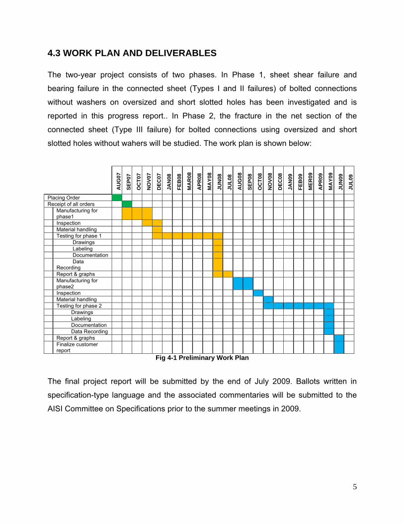
4.3 WORK PLAN AND DELIVERABLES
The two-year project consists of two phases. In Phase 1, sheet shear failure and
bearing failure in the connected sheet (Types I and II failures) of bolted connections
without washers on oversized and short slotted holes has been investigated and is
reported in this progress report.. In Phase 2, the fracture in the net section of the
connected sheet (Type III failure) for bolted connections using oversized and short
slotted holes without wahers will be studied. The work plan is shown below:
AU
G07
SEP0
7
OC
T07
NO
V07
DEC
07
JAN
08
FEB
08
MA
R08
APR
08
MA
Y08
JUN
08
JUL0
8
AU
G08
SEP0
8
OC
T08
NO
V08
DEC
08
JAN
09
FEB
09
MER
09
APR
09
MA
Y09
JUN
09
JUL0
9
Placing Order Receipt of all orders Manufacturing for
phase1
Inspection Material handling Testing for phase 1 Drawings Labeling Documentation Data
Recording
Report & graphs Manufacturing for
phase2
Inspection Material handling Testing for phase 2 Drawings Labeling Documentation Data Recording Report & graphs Finalize customer
report
Fig 4-1 Preliminary Work Plan
The final project report will be submitted by the end of July 2009. Ballots written in
specification-type language and the associated commentaries will be submitted to the
AISI Committee on Specifications prior to the summer meetings in 2009.
6
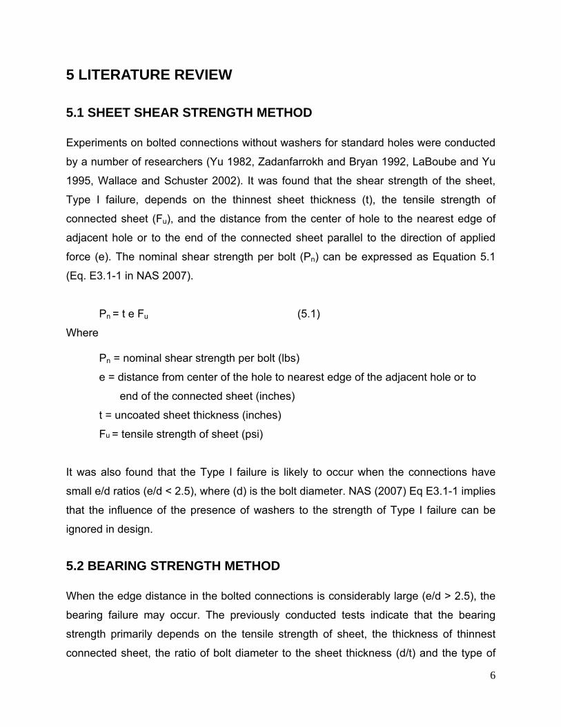
5 LITERATURE REVIEW
5.1 SHEET SHEAR STRENGTH METHOD
Experiments on bolted connections without washers for standard holes were conducted
by a number of researchers (Yu 1982, Zadanfarrokh and Bryan 1992, LaBoube and Yu
1995, Wallace and Schuster 2002). It was found that the shear strength of the sheet,
Type I failure, depends on the thinnest sheet thickness (t), the tensile strength of
connected sheet (Fu), and the distance from the center of hole to the nearest edge of
adjacent hole or to the end of the connected sheet parallel to the direction of applied
force (e). The nominal shear strength per bolt (Pn) can be expressed as Equation 5.1
(Eq. E3.1-1 in NAS 2007).
Pn = t e Fu (5.1)
Where
Pn = nominal shear strength per bolt (lbs)
e = distance from center of the hole to nearest edge of the adjacent hole or to
end of the connected sheet (inches)
t = uncoated sheet thickness (inches)
Fu = tensile strength of sheet (psi)
It was also found that the Type I failure is likely to occur when the connections have
small e/d ratios (e/d < 2.5), where (d) is the bolt diameter. NAS (2007) Eq E3.1-1 implies
that the influence of the presence of washers to the strength of Type I failure can be
ignored in design.
5.2 BEARING STRENGTH METHOD
When the edge distance in the bolted connections is considerably large (e/d > 2.5), the
bearing failure may occur. The previously conducted tests indicate that the bearing
strength primarily depends on the tensile strength of sheet, the thickness of thinnest
connected sheet, the ratio of bolt diameter to the sheet thickness (d/t) and the type of
7
bearing connection (single or double shear, with or without washers, etc) (Yu 1982,
Zadanfarrokh & Bryan 1992, LaBoube & Yu 1995, Wallace & Schuster 2001, 2002). The
presence of washers has significant impact on the bearing strength. The current design
method for bearing strength in NAS (2007) was based on the research done by Wallace,
Schuster, and LaBoube (2001, 2002) in which the Waterloo method and current NAS
method were developed.
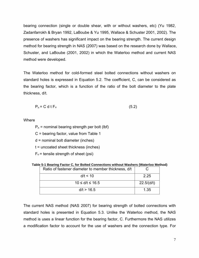
The Waterloo method for cold-formed steel bolted connections without washers on
standard holes is expressed in Equation 5.2. The coefficient, C, can be considered as
the bearing factor, which is a function of the ratio of the bolt diameter to the plate
thickness, d/t.
Pn = C d t Fu (5.2)
Where
Pn = nominal bearing strength per bolt (lbf)
C = bearing factor, value from Table 1
d = nominal bolt diameter (inches)
t = uncoated sheet thickness (inches)
Fu = tensile strength of sheet (psi)
Table 5-1 Bearing Factor C, for Bolted Connections without Washers (Waterloo Method)
Ratio of fastener diameter to member thickness, d/t C
d/t < 10 2.25
10 ≤ d/t ≤ 16.5 22.5/(d/t)
d/t > 16.5 1.35
The current NAS method (NAS 2007) for bearing strength of bolted connections with
standard holes is presented in Equation 5.3. Unlike the Waterloo method, the NAS
method is uses a linear function for the bearing factor, C. Furthermore the NAS utilizes
a modification factor to account for the use of washers and the connection type. For
8
single shear connections without a washer with standard holes, the modification factor
equals 0.75, while a factor of 1.33 is used for the inside sheet of double shear
connections without washers.
Pn = mf C d t Fu (5.3)
Where
Pn = nominal bearing strength per bolt (lbf)
mf = modification factor (0.75 for single shear without washers, 1.33 for inside
sheet of double shear)
C = bearing factor, value from Table 2
d = nominal bolt diameter (inches)
t = uncoated sheet thickness (inches)
Fu = tensile strength of sheet (psi)
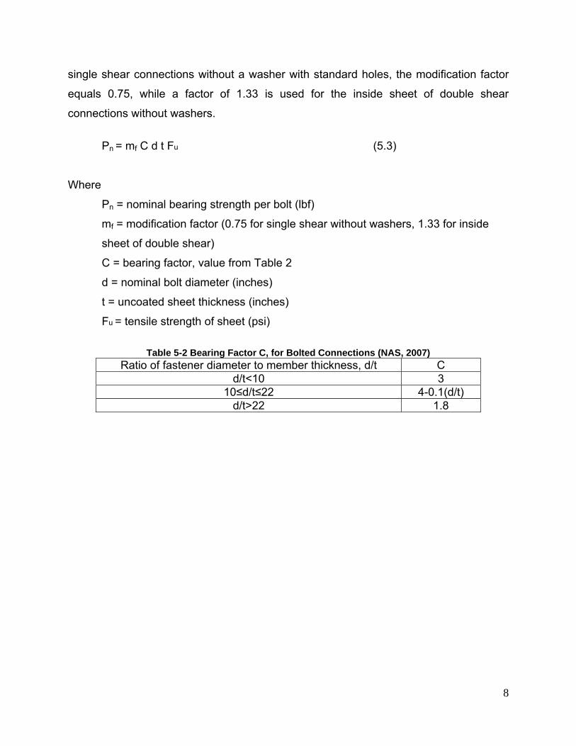
Table 5-2 Bearing Factor C, for Bolted Connections (NAS, 2007)
Ratio of fastener diameter to member thickness, d/t C d/t<10 3
10≤d/t≤22 4-0.1(d/t) d/t>22 1.8
9
6 TEST SETUP
6.1 TESTING EQUIPMENTS AND METHOD FOR CONNECTION TESTS
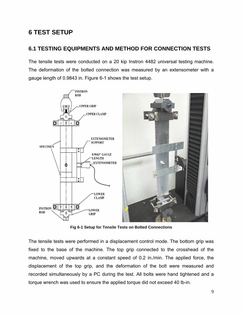
The tensile tests were conducted on a 20 kip Instron 4482 universal testing machine.
The deformation of the bolted connection was measured by an extensometer with a
gauge length of 0.9843 in. Figure 6-1 shows the test setup.
Fig 6-1 Setup for Tensile Tests on Bolted Connections
The tensile tests were performed in a displacement control mode. The bottom grip was
fixed to the base of the machine. The top grip connected to the crosshead of the
machine, moved upwards at a constant speed of 0.2 in./min. The applied force, the
displacement of the top grip, and the deformation of the bolt were measured and
recorded simultaneously by a PC during the test. All bolts were hand tightened and a
torque wrench was used to ensure the applied torque did not exceed 40 lb-in.
10
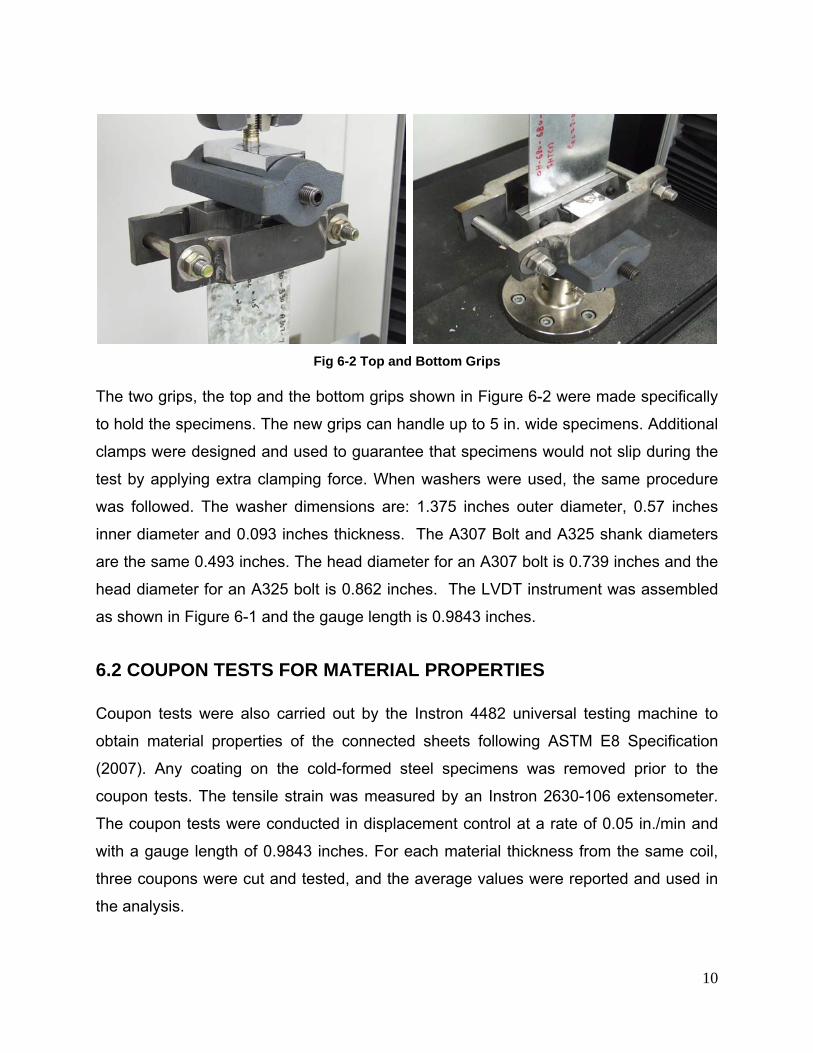
Fig 6-2 Top and Bottom Grips
The two grips, the top and the bottom grips shown in Figure 6-2 were made specifically
to hold the specimens. The new grips can handle up to 5 in. wide specimens. Additional
clamps were designed and used to guarantee that specimens would not slip during the
test by applying extra clamping force. When washers were used, the same procedure
was followed. The washer dimensions are: 1.375 inches outer diameter, 0.57 inches
inner diameter and 0.093 inches thickness. The A307 Bolt and A325 shank diameters
are the same 0.493 inches. The head diameter for an A307 bolt is 0.739 inches and the
head diameter for an A325 bolt is 0.862 inches. The LVDT instrument was assembled
as shown in Figure 6-1 and the gauge length is 0.9843 inches.
6.2 COUPON TESTS FOR MATERIAL PROPERTIES
Coupon tests were also carried out by the Instron 4482 universal testing machine to
obtain material properties of the connected sheets following ASTM E8 Specification
(2007). Any coating on the cold-formed steel specimens was removed prior to the
coupon tests. The tensile strain was measured by an Instron 2630-106 extensometer.
The coupon tests were conducted in displacement control at a rate of 0.05 in./min and
with a gauge length of 0.9843 inches. For each material thickness from the same coil,
three coupons were cut and tested, and the average values were reported and used in
the analysis.
11
7 TEST SPECIMENS
7.1 SPECIMEN CONFIGURATIONS
For both phases, the test matrix covers:
• Cold-formed steel sheet thicknesses ranged from 30 mil to 118 mil.
• Single shear and double shear connections with one bolt and two bolts.
• ASTM A307 Type A bolts (0.5 in. diameter, 1.25 in. long and 0.25 in. diameter, 1 in.
long) and A325 bolts (0.5 in. diameter, 1.25 in. long) were used. Washers were not
installed for the main test group.
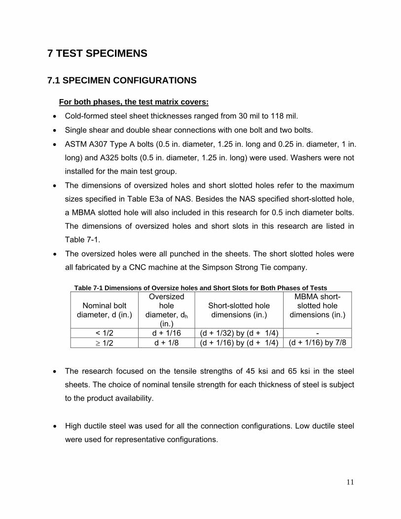
• The dimensions of oversized holes and short slotted holes refer to the maximum
sizes specified in Table E3a of NAS. Besides the NAS specified short-slotted hole,
a MBMA slotted hole will also included in this research for 0.5 inch diameter bolts.
The dimensions of oversized holes and short slots in this research are listed in
Table 7-1.
• The oversized holes were all punched in the sheets. The short slotted holes were
all fabricated by a CNC machine at the Simpson Strong Tie company.
Table 7-1 Dimensions of Oversize holes and Short Slots for Both Phases of Tests
Nominal bolt diameter, d (in.)
Oversized hole
diameter, dh (in.)
Short-slotted hole dimensions (in.)
MBMA short-slotted hole
dimensions (in.)
< 1/2 d + 1/16 (d + 1/32) by (d + 1/4) - ≥ 1/2 d + 1/8 (d + 1/16) by (d + 1/4) (d + 1/16) by 7/8
• The research focused on the tensile strengths of 45 ksi and 65 ksi in the steel
sheets. The choice of nominal tensile strength for each thickness of steel is subject
to the product availability.
• High ductile steel was used for all the connection configurations. Low ductile steel
were used for representative configurations.
12
The details of specimens for each phase are provided in the following sections.
Specimens of Phase 1 Tests Sheet shear failure and bearing failure in the connected sheets (Type I and II
failures) are the primary concerns in Phase 1 of the research. Therefore, the
dimensions of specimens and test matrices were designed to ensure the occurrence
of the desired failure mode.
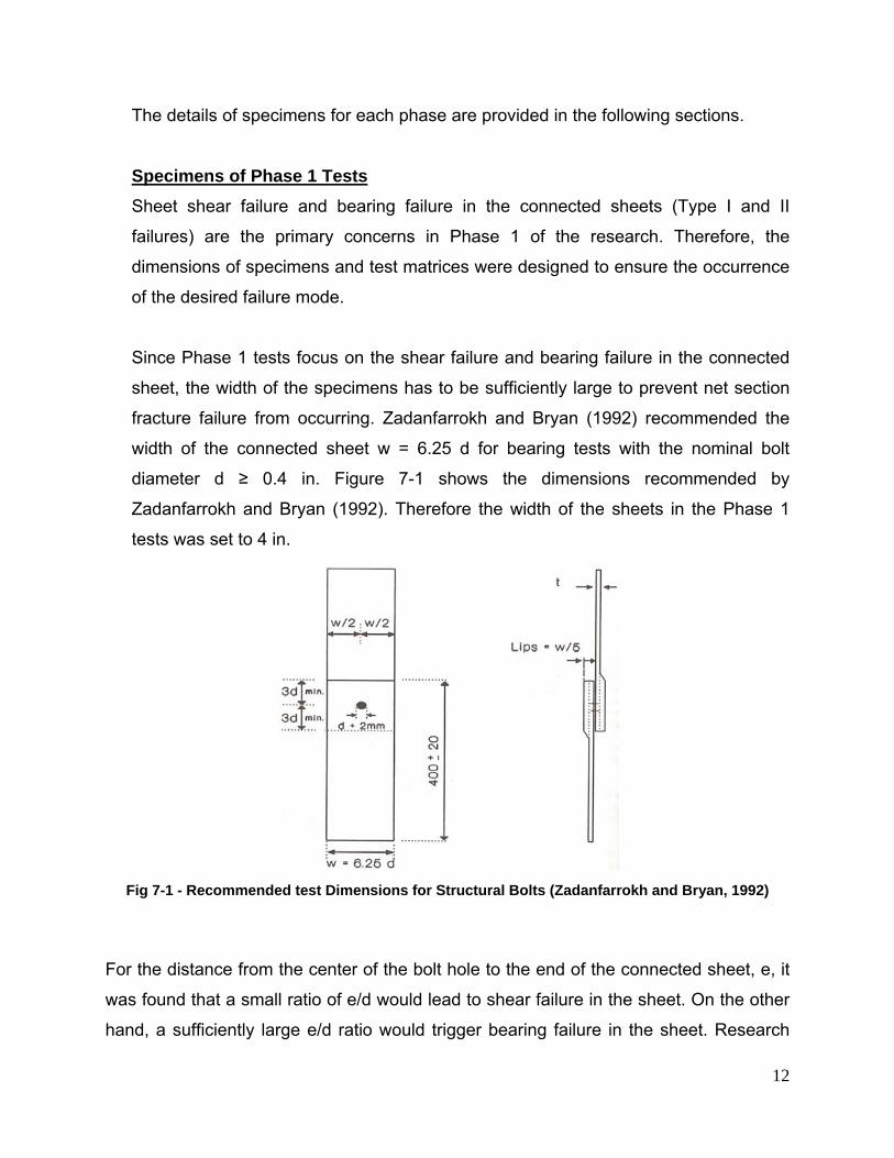
Since Phase 1 tests focus on the shear failure and bearing failure in the connected
sheet, the width of the specimens has to be sufficiently large to prevent net section
fracture failure from occurring. Zadanfarrokh and Bryan (1992) recommended the
width of the connected sheet w = 6.25 d for bearing tests with the nominal bolt
diameter d ≥ 0.4 in. Figure 7-1 shows the dimensions recommended by
Zadanfarrokh and Bryan (1992). Therefore the width of the sheets in the Phase 1
tests was set to 4 in.
Fig 7-1 - Recommended test Dimensions for Structural Bolts (Zadanfarrokh and Bryan, 1992)
For the distance from the center of the bolt hole to the end of the connected sheet, e, it
was found that a small ratio of e/d would lead to shear failure in the sheet. On the other
hand, a sufficiently large e/d ratio would trigger bearing failure in the sheet. Research

13
done by Chong and Matlock (1975), Gilchrist and Chong (1979), Yu (1982) indicated
that e/d = 2.5 is approximately the transition point to distinguish between those two
types of failures. Furthermore, the NAS (2007) requires a minimum e/d = 1.5 for cold-
formed steel bolted connections. Therefore, e/d values in the proposed Phase 1 tests
were chosen to be 4 for bearing failure and 1.5 for sheet shear failure. The length of
each connected sheet, from edge to edge, was set to 15 in. which is based on the
recommended value by Zadanfarrokh and Bryan (1992).
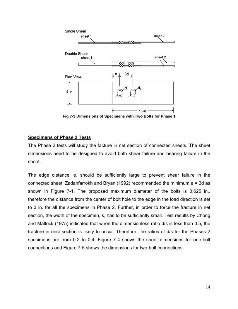
The sheet dimensions for the Phase 1 tests are shown in Figure 7-2 for one-bolt
connections and in Figure 7-3 for two bolt connections. The distance between centers of
bolt holes for the two-bolt connections equals to three times the nominal bolt diameter,
d, which is based on the spacing requirement in Section E3.1 of the NAS (2007).
sheet 1 sheet 2
sheet 1 sheet 2
dh4 in.
15 in.
Single Shear
Double Shear
Plan View (with hole or short slot)e
Fig 7-2 Dimensions of Specimens with One Bolt for Phase 1
14
sheet 1 sheet 2
sheet 1 sheet 2
15 in.
Single Shear
Double Shear
Plan View
dh dh
e
4 in
3d
sheet 1 sheet 2
sheet 1 sheet 2
15 in.
Single Shear
Double Shear
Plan View
dh dh
e
4 in
3d
Fig 7-3 Dimensions of Specimens with Two Bolts for Phase 1
Specimens of Phase 2 Tests The Phase 2 tests will study the facture in net section of connected sheets. The sheet
dimensions need to be designed to avoid both shear failure and bearing failure in the
sheet.
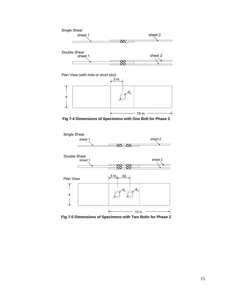
The edge distance, e, should be sufficiently large to prevent shear failure in the
connected sheet. Zadanfarrokh and Bryan (1992) recommended the minimum e = 3d as
shown in Figure 7-1. The proposed maximum diameter of the bolts is 0.625 in.,
therefore the distance from the center of bolt hole to the edge in the load direction is set
to 3 in. for all the specimens in Phase 2. Further, in order to force the fracture in net
section, the width of the specimen, s, has to be sufficiently small. Test results by Chong
and Matlock (1975) indicated that when the dimensionless ratio d/s is less than 0.5, the
fracture in nest section is likely to occur. Therefore, the ratios of d/s for the Phases 2
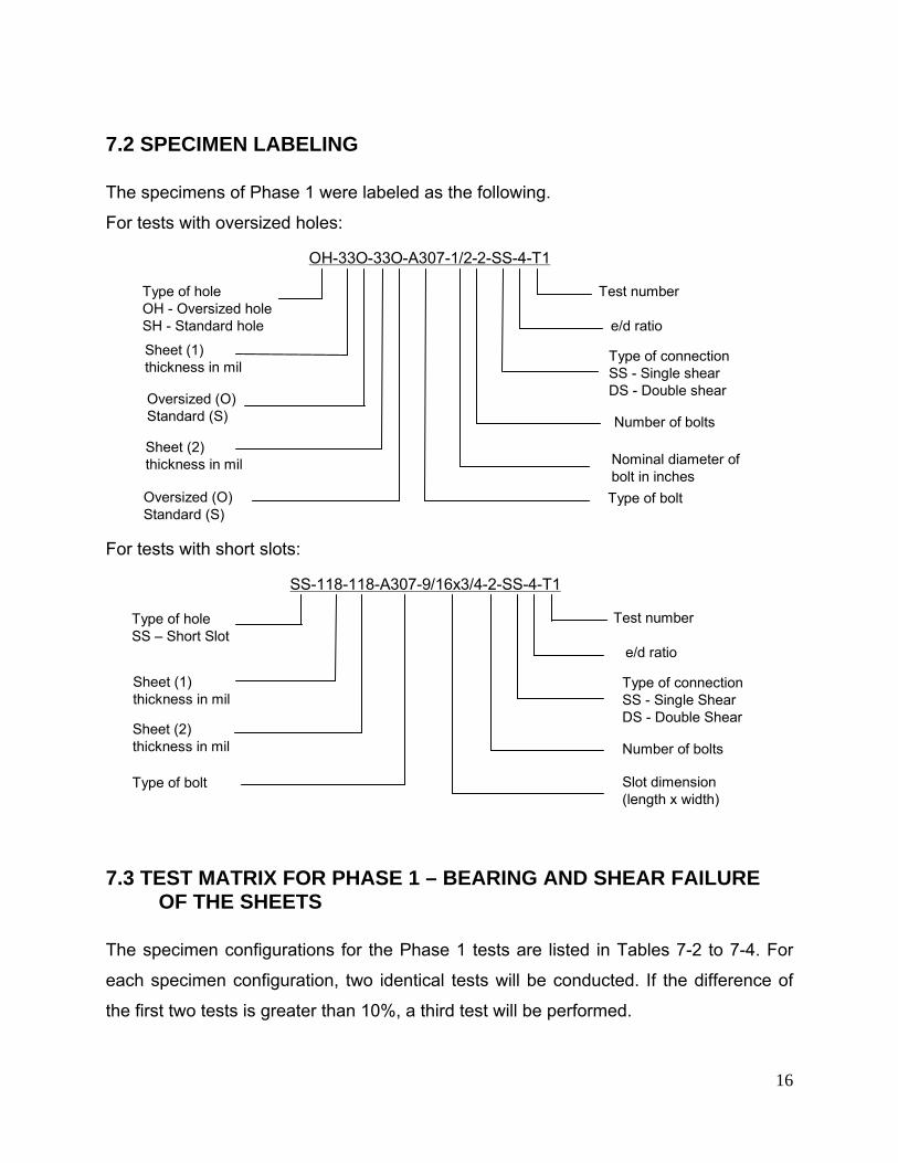
specimens are from 0.2 to 0.4. Figure 7-4 shows the sheet dimensions for one-bolt
connections and Figure 7-5 shows the dimensions for two-bolt connections.
15
sheet 1 sheet 2
sheet 1 sheet 2
dhs
15 in.
Single Shear
Double Shear
Plan View (with hole or short slot)3 in.
Fig 7-4 Dimensions of Specimens with One Bolt for Phase 2
sheet 1 sheet 2
sheet 1 sheet 2
15 in.
Single Shear
Double Shear
Plan View
dh dh
3 in.
s
3d
Fig 7-5 Dimensions of Specimens with Two Bolts for Phase 2
16
7.2 SPECIMEN LABELING
The specimens of Phase 1 were labeled as the following.
For tests with oversized holes:
OH-33O-33O-A307-1/2-2-SS-4-T1
Type of hole OH - Oversized holeSH - Standard hole
Sheet (1) thickness in mil
Sheet (2) thickness in mil
Type of bolt
Nominal diameter of bolt in inches
Number of bolts
Type of connection SS - Single shearDS - Double shear
e/d ratio
Test number
Oversized (O)Standard (S)
Oversized (O)Standard (S)
For tests with short slots:
SS-118-118-A307-9/16x3/4-2-SS-4-T1
Type of hole SS – Short Slot
Sheet (1) thickness in mil
Sheet (2) thickness in mil
Type of bolt Slot dimension(length x width)
Number of bolts
Type of connection SS - Single ShearDS - Double Shear
e/d ratio
Test number
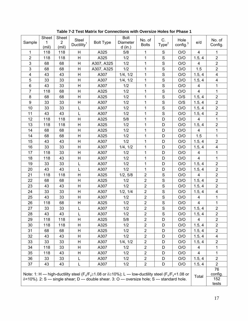
7.3 TEST MATRIX FOR PHASE 1 – BEARING AND SHEAR FAILURE OF THE SHEETS
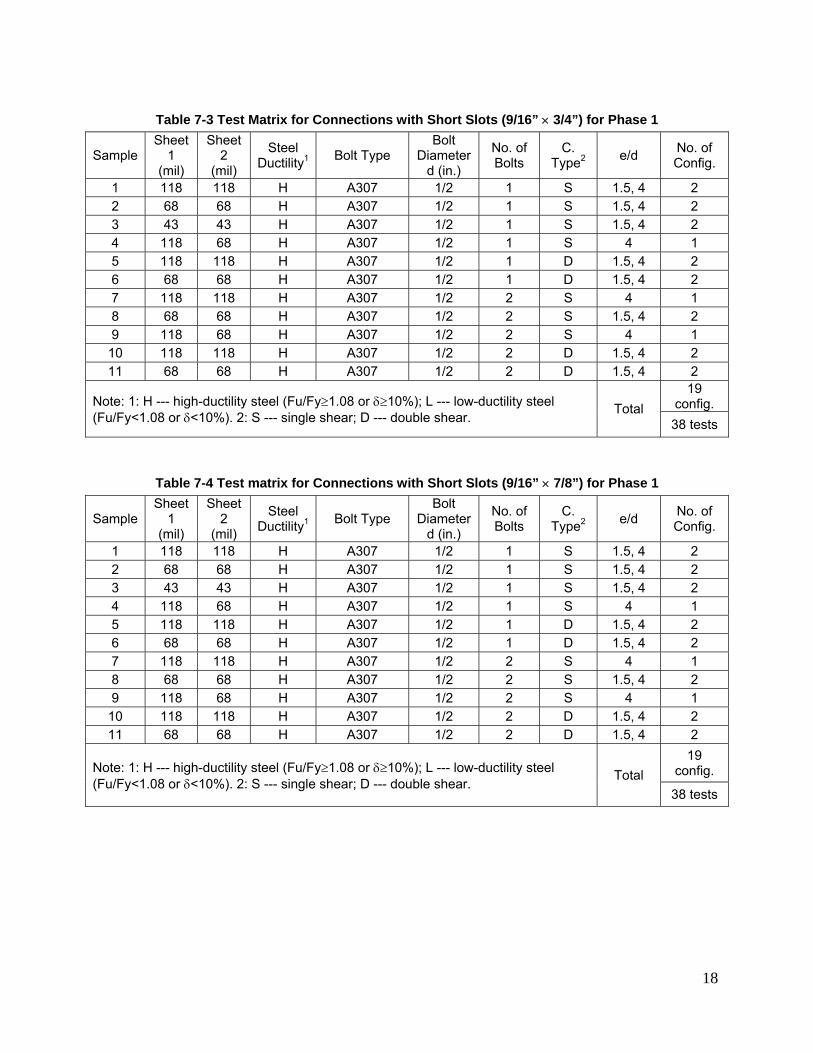
The specimen configurations for the Phase 1 tests are listed in Tables 7-2 to 7-4. For
each specimen configuration, two identical tests will be conducted. If the difference of
the first two tests is greater than 10%, a third test will be performed.
17
Table 7-2 Test Matrix for Connections with Oversize Holes for Phase 1
Sample Sheet
1 (mil)
Sheet 2
(mil)
Steel Ductility1 Bolt Type
Bolt Diameter
d (in.)
No. of Bolts
C. Type2
Hole config.3 e/d No. of
Config.
1 118 118 H A325 5/8 1 S O/O 4 1 2 118 118 H A325 1/2 1 S O/O 1.5, 4 2 3 68 68 H A307, A325 1/2 1 S O/O 4 2 3 68 68 H A307, A325 1/2 1 S O/O 1.5 2 4 43 43 H A307 1/4, 1/2 1 S O/O 1.5, 4 4 5 33 33 H A307 1/4, 1/2 1 S O/O 1.5, 4 4 6 43 33 H A307 1/2 1 S O/O 4 1 7 118 68 H A325 1/2 1 S O/O 4 1 8 68 68 H A325 1/2 1 S O/S 1.5, 4 2 9 33 33 H A307 1/2 1 S O/S 1.5, 4 2 10 33 33 L A307 1/2 1 S O/O 1.5, 4 2 11 43 43 L A307 1/2 1 S O/O 1.5, 4 2 12 118 118 H A325 5/8 1 D O/O 4 1 13 118 118 H A325 1/2 1 D O/O 1.5, 4 2 14 68 68 H A325 1/2 1 D O/O 4 1 14 68 68 H A325 1/2 1 D O/O 1.5 1 15 43 43 H A307 1/2 1 D O/O 1.5, 4 2 16 33 33 H A307 1/4, 1/2 1 D O/O 1.5, 4 4 17 118 33 H A307 1/2 1 D O/O 4 1 18 118 43 H A307 1/2 1 D O/O 4 1 19 33 33 L A307 1/2 1 D O/O 1.5, 4 2 20 43 43 L A307 1/2 1 D O/O 1.5, 4 2 21 118 118 H A325 1/2, 5/8 2 S O/O 4 2 22 68 68 H A325 1/2 2 S O/O 1.5, 4 2 23 43 43 H A307 1/2 2 S O/O 1.5, 4 2 24 33 33 H A307 1/2, 1/4 2 S O/O 1.5, 4 4 25 43 33 H A307 1/2 2 S O/O 4 1 26 118 68 H A325 1/2 2 S O/O 4 1 27 33 33 L A307 1/2 2 S O/O 1.5, 4 2 28 43 43 L A307 1/2 2 S O/O 1.5, 4 2 29 118 118 H A325 5/8 2 D O/O 4 2 30 118 118 H A325 1/2 2 D O/O 1.5, 4 2 31 68 68 H A325 1/2 2 D O/O 1.5, 4 2 32 43 43 H A307 1/2 2 D O/O 1.5, 4 4 33 33 33 H A307 1/4, 1/2 2 D O/O 1.5, 4 2 34 118 33 H A307 1/2 2 D O/O 4 1 35 118 43 H A307 1/2 2 D O/O 4 1 36 33 33 L A307 1/2 2 D O/O 1.5, 4 2 37 43 43 L A307 1/2 2 D O/O 1.5, 4 2
Note: 1: H --- high-ductility steel (Fu/Fy≥1.08 or δ≥10%); L --- low-ductility steel (Fu/Fy<1.08 or δ<10%). 2: S --- single shear; D --- double shear. 3: O --- oversize hole; S --- standard hole. Total
76 config.
152 tests
18
Table 7-3 Test Matrix for Connections with Short Slots (9/16” × 3/4”) for Phase 1
Sample Sheet
1 (mil)
Sheet 2
(mil)
Steel Ductility1 Bolt Type
Bolt Diameter
d (in.)
No. of Bolts
C. Type2 e/d No. of
Config.
1 118 118 H A307 1/2 1 S 1.5, 4 2 2 68 68 H A307 1/2 1 S 1.5, 4 2 3 43 43 H A307 1/2 1 S 1.5, 4 2 4 118 68 H A307 1/2 1 S 4 1 5 118 118 H A307 1/2 1 D 1.5, 4 2 6 68 68 H A307 1/2 1 D 1.5, 4 2 7 118 118 H A307 1/2 2 S 4 1 8 68 68 H A307 1/2 2 S 1.5, 4 2 9 118 68 H A307 1/2 2 S 4 1 10 118 118 H A307 1/2 2 D 1.5, 4 2 11 68 68 H A307 1/2 2 D 1.5, 4 2
Note: 1: H --- high-ductility steel (Fu/Fy≥1.08 or δ≥10%); L --- low-ductility steel (Fu/Fy<1.08 or δ<10%). 2: S --- single shear; D --- double shear. Total
19 config. 38 tests
Table 7-4 Test matrix for Connections with Short Slots (9/16” × 7/8”) for Phase 1
Sample Sheet
1 (mil)
Sheet 2
(mil)
Steel Ductility1 Bolt Type
Bolt Diameter
d (in.)
No. of Bolts
C. Type2 e/d No. of
Config.
1 118 118 H A307 1/2 1 S 1.5, 4 2 2 68 68 H A307 1/2 1 S 1.5, 4 2 3 43 43 H A307 1/2 1 S 1.5, 4 2 4 118 68 H A307 1/2 1 S 4 1 5 118 118 H A307 1/2 1 D 1.5, 4 2 6 68 68 H A307 1/2 1 D 1.5, 4 2 7 118 118 H A307 1/2 2 S 4 1 8 68 68 H A307 1/2 2 S 1.5, 4 2 9 118 68 H A307 1/2 2 S 4 1 10 118 118 H A307 1/2 2 D 1.5, 4 2 11 68 68 H A307 1/2 2 D 1.5, 4 2
Note: 1: H --- high-ductility steel (Fu/Fy≥1.08 or δ≥10%); L --- low-ductility steel (Fu/Fy<1.08 or δ<10%). 2: S --- single shear; D --- double shear. Total
19 config.
38 tests
19
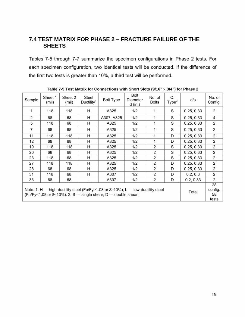
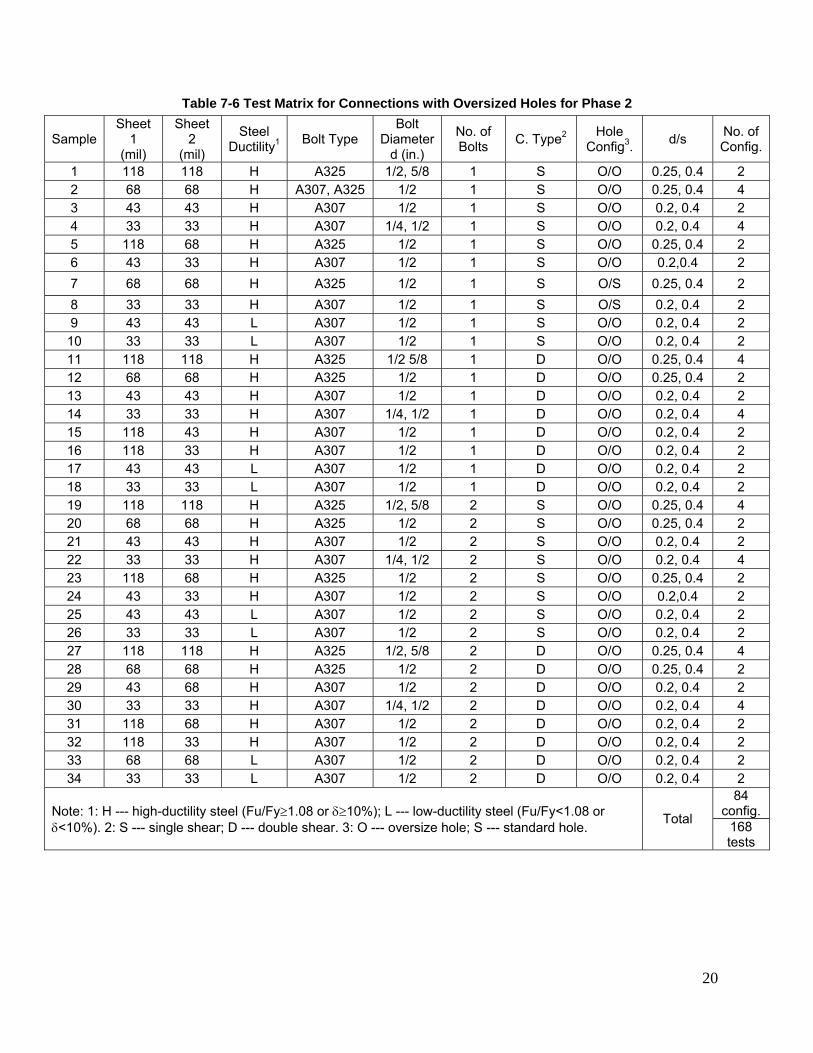
7.4 TEST MATRIX FOR PHASE 2 – FRACTURE FAILURE OF THE SHEETS
Tables 7-5 through 7-7 summarize the specimen configurations in Phase 2 tests. For
each specimen configuration, two identical tests will be conducted. If the difference of
the first two tests is greater than 10%, a third test will be performed.
Table 7-5 Test Matrix for Connections with Short Slots (9/16” × 3/4”) for Phase 2
Sample Sheet 1 (mil)
Sheet 2 (mil)
Steel Ductility1 Bolt Type
Bolt Diameter
d (in.)
No. of Bolts
C. Type2 d/s No. of
Config.
1 118 118 H A325 1/2 1 S 0.25, 0.33 2
2 68 68 H A307, A325 1/2 1 S 0.25, 0.33 4 5 118 68 H A325 1/2 1 S 0.25, 0.33 2 7 68 68 H A325 1/2 1 S 0.25, 0.33 2 11 118 118 H A325 1/2 1 D 0.25, 0.33 2 12 68 68 H A325 1/2 1 D 0.25, 0.33 2 19 118 118 H A325 1/2 2 S 0.25, 0.33 2 20 68 68 H A325 1/2 2 S 0.25, 0.33 2 23 118 68 H A325 1/2 2 S 0.25, 0.33 2 27 118 118 H A325 1/2 2 D 0.25, 0.33 2 28 68 68 H A325 1/2 2 D 0.25, 0.33 2 31 118 68 H A307 1/2 2 D 0.2, 0.3 2 33 68 68 L A307 1/2 2 D 0.2, 0.33 2
Note: 1: H --- high-ductility steel (Fu/Fy≥1.08 or δ≥10%); L --- low-ductility steel (Fu/Fy<1.08 or δ<10%). 2: S --- single shear; D --- double shear. Total
28 config.
58 tests
20
Table 7-6 Test Matrix for Connections with Oversized Holes for Phase 2
Sample Sheet
1 (mil)
Sheet 2
(mil)
Steel Ductility1 Bolt Type
Bolt Diameter
d (in.)
No. of Bolts C. Type2 Hole
Config3. d/s No. of Config.
1 118 118 H A325 1/2, 5/8 1 S O/O 0.25, 0.4 2 2 68 68 H A307, A325 1/2 1 S O/O 0.25, 0.4 4 3 43 43 H A307 1/2 1 S O/O 0.2, 0.4 2 4 33 33 H A307 1/4, 1/2 1 S O/O 0.2, 0.4 4 5 118 68 H A325 1/2 1 S O/O 0.25, 0.4 2 6 43 33 H A307 1/2 1 S O/O 0.2,0.4 2 7 68 68 H A325 1/2 1 S O/S 0.25, 0.4 2 8 33 33 H A307 1/2 1 S O/S 0.2, 0.4 2 9 43 43 L A307 1/2 1 S O/O 0.2, 0.4 2 10 33 33 L A307 1/2 1 S O/O 0.2, 0.4 2 11 118 118 H A325 1/2 5/8 1 D O/O 0.25, 0.4 4 12 68 68 H A325 1/2 1 D O/O 0.25, 0.4 2 13 43 43 H A307 1/2 1 D O/O 0.2, 0.4 2 14 33 33 H A307 1/4, 1/2 1 D O/O 0.2, 0.4 4 15 118 43 H A307 1/2 1 D O/O 0.2, 0.4 2 16 118 33 H A307 1/2 1 D O/O 0.2, 0.4 2 17 43 43 L A307 1/2 1 D O/O 0.2, 0.4 2 18 33 33 L A307 1/2 1 D O/O 0.2, 0.4 2 19 118 118 H A325 1/2, 5/8 2 S O/O 0.25, 0.4 4 20 68 68 H A325 1/2 2 S O/O 0.25, 0.4 2 21 43 43 H A307 1/2 2 S O/O 0.2, 0.4 2 22 33 33 H A307 1/4, 1/2 2 S O/O 0.2, 0.4 4 23 118 68 H A325 1/2 2 S O/O 0.25, 0.4 2 24 43 33 H A307 1/2 2 S O/O 0.2,0.4 2 25 43 43 L A307 1/2 2 S O/O 0.2, 0.4 2 26 33 33 L A307 1/2 2 S O/O 0.2, 0.4 2 27 118 118 H A325 1/2, 5/8 2 D O/O 0.25, 0.4 4 28 68 68 H A325 1/2 2 D O/O 0.25, 0.4 2 29 43 68 H A307 1/2 2 D O/O 0.2, 0.4 2 30 33 33 H A307 1/4, 1/2 2 D O/O 0.2, 0.4 4 31 118 68 H A307 1/2 2 D O/O 0.2, 0.4 2 32 118 33 H A307 1/2 2 D O/O 0.2, 0.4 2 33 68 68 L A307 1/2 2 D O/O 0.2, 0.4 2 34 33 33 L A307 1/2 2 D O/O 0.2, 0.4 2
Note: 1: H --- high-ductility steel (Fu/Fy≥1.08 or δ≥10%); L --- low-ductility steel (Fu/Fy<1.08 or δ<10%). 2: S --- single shear; D --- double shear. 3: O --- oversize hole; S --- standard hole. Total
84 config.
168 tests
21
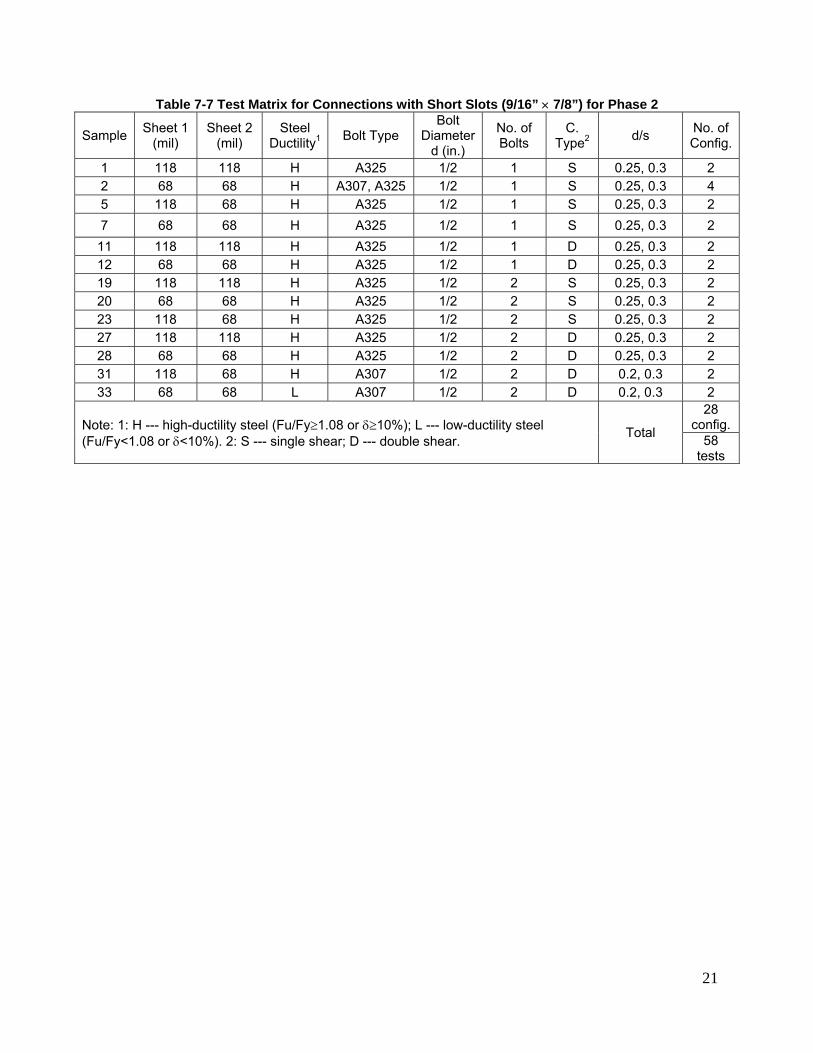
Table 7-7 Test Matrix for Connections with Short Slots (9/16” × 7/8”) for Phase 2
Sample Sheet 1 (mil)
Sheet 2 (mil)
Steel Ductility1 Bolt Type
Bolt Diameter
d (in.)
No. of Bolts
C. Type2 d/s No. of
Config.
1 118 118 H A325 1/2 1 S 0.25, 0.3 2 2 68 68 H A307, A325 1/2 1 S 0.25, 0.3 4 5 118 68 H A325 1/2 1 S 0.25, 0.3 2 7 68 68 H A325 1/2 1 S 0.25, 0.3 2 11 118 118 H A325 1/2 1 D 0.25, 0.3 2 12 68 68 H A325 1/2 1 D 0.25, 0.3 2 19 118 118 H A325 1/2 2 S 0.25, 0.3 2 20 68 68 H A325 1/2 2 S 0.25, 0.3 2 23 118 68 H A325 1/2 2 S 0.25, 0.3 2 27 118 118 H A325 1/2 2 D 0.25, 0.3 2 28 68 68 H A325 1/2 2 D 0.25, 0.3 2 31 118 68 H A307 1/2 2 D 0.2, 0.3 2 33 68 68 L A307 1/2 2 D 0.2, 0.3 2
Note: 1: H --- high-ductility steel (Fu/Fy≥1.08 or δ≥10%); L --- low-ductility steel (Fu/Fy<1.08 or δ<10%). 2: S --- single shear; D --- double shear. Total
28 config.
58 tests
22
8 TEST RESULTS
8.1 COUPON TESTS FOR MATERIAL PROPERTIES
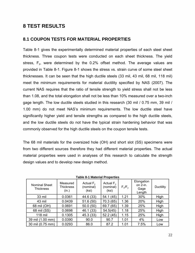
Table 8-1 gives the experimentally determined material properties of each steel sheet
thickness. Three coupon tests were conducted on each sheet thickness. The yield
stress, Fy, were determined by the 0.2% offset method. The average values are
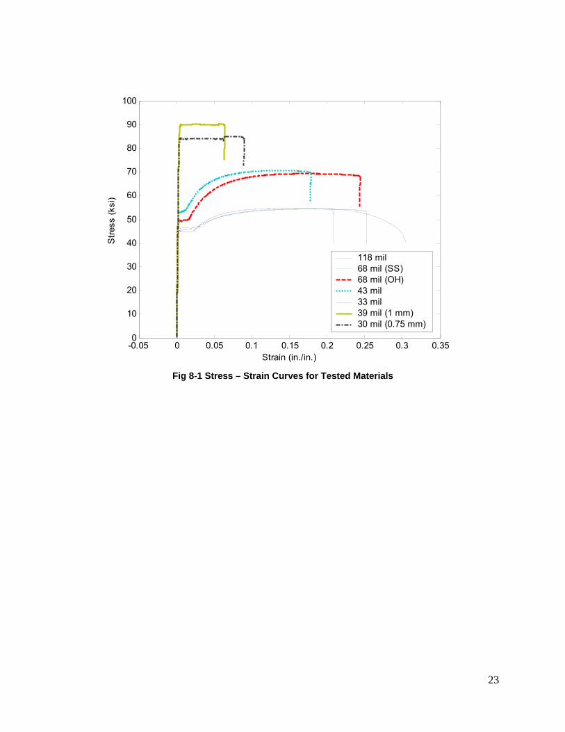
provided in Table 8-1. Figure 8-1 shows the stress vs. strain curve of some steel sheet
thicknesses. It can be seen that the high ductile steels (33 mil, 43 mil, 68 mil, 118 mil)
meet the minimum requirements for material ductility specified by NAS (2007). The
current NAS requires that the ratio of tensile strength to yield stress shall not be less
than 1.08, and the total elongation shall not be less than 10% measured over a two-inch
gage length. The low ductile steels studied in this research (30 mil / 0.75 mm, 39 mil /
1.00 mm) do not meet NAS’s minimum requirements. The low ductile steel have
significantly higher yield and tensile strengths as compared to the high ductile steels,
and the low ductile steels do not have the typical strain hardening behavior that was
commonly observed for the high ductile steels on the coupon tensile tests.
The 68 mil materials for the oversized hole (OH) and short slot (SS) specimens were
from two different sources therefore they had different material properties. The actual
material properties were used in analyses of this research to calculate the strength
design values and to develop new design method.
Table 8-1 Material Properties
Nominal Sheet Thickness
Measured Thickness
(in.)
Actual Fy (nominal)
(ksi)
Actual Fu (nominal)
(ksi) Fu/Fy
Elongation on 2-in. Gage
Length
Ductility
33 mil 0.0361 44.6 (33) 54.1 (45) 1.21 30% High 43 mil 0.0439 51.6 (50) 70.3 (65) 1.36 20% High
68 mil (OH) 0.0691 50.0 (50) 69.7 (65) 1.39 25% High 68 mil (SS) 0.0698 46.1 (33) 54.5(45) 1.18 25% High
118 mil 0.1305 45.3 (33) 52.2 (45) 1.15 25% High 39 mil (1.00 mm) 0.0390 90.0 90.7 1.01 4% Low 30 mil (0.75 mm) 0.0293 86.0 87.2 1.01 7.5% Low
23
-0.05 0 0.05 0.1 0.15 0.2 0.25 0.3 0.350
10
20
30
40
50
60
70
80
90
100S
tress
(ksi
)
Strain (in./in.)
118 mil68 mil (SS)68 mil (OH)43 mil33 mil39 mil (1 mm)30 mil (0.75 mm)
Fig 8-1 Stress – Strain Curves for Tested Materials
24
8.2 TENSILE TESTS ON BOLTED CONNECTIONS WITHOUT WASHERS ON OVERSIZED HOLES (MAIN GROUP)
8.2.1 Sheet Bearing Failure
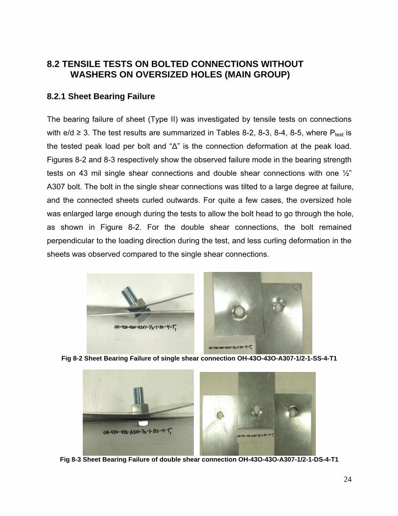
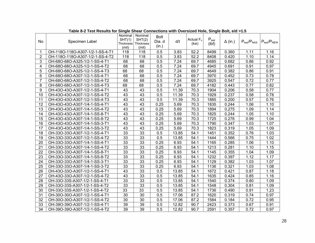
The bearing failure of sheet (Type II) was investigated by tensile tests on connections
with e/d ≥ 3. The test results are summarized in Tables 8-2, 8-3, 8-4, 8-5, where Ptest is
the tested peak load per bolt and “Δ” is the connection deformation at the peak load.
Figures 8-2 and 8-3 respectively show the observed failure mode in the bearing strength
tests on 43 mil single shear connections and double shear connections with one ½”
A307 bolt. The bolt in the single shear connections was tilted to a large degree at failure,
and the connected sheets curled outwards. For quite a few cases, the oversized hole
was enlarged large enough during the tests to allow the bolt head to go through the hole,
as shown in Figure 8-2. For the double shear connections, the bolt remained
perpendicular to the loading direction during the test, and less curling deformation in the
sheets was observed compared to the single shear connections.
Fig 8-2 Sheet Bearing Failure of single shear connection OH-43O-43O-A307-1/2-1-SS-4-T1
Fig 8-3 Sheet Bearing Failure of double shear connection OH-43O-43O-A307-1/2-1-DS-4-T1
25
0 0.2 0.4 0.6 0.8 1 1.20
500
1000
1500
2000
2500
3000
3500
4000
Deformation (in.)
App
lied
load
per
bol
t (lb
s)OH-43O-43O-A307-1/2-1-SS-4-T2OH-43O-43O-A307-1/2-1-DS-4-T1
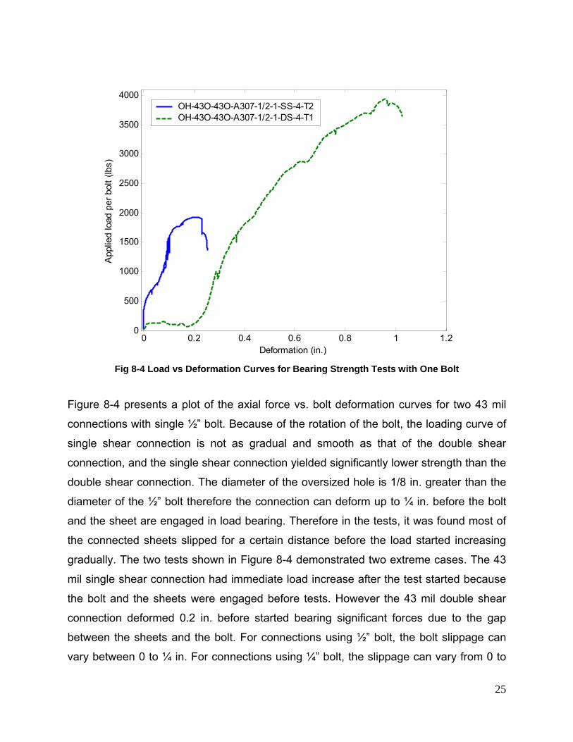
Fig 8-4 Load vs Deformation Curves for Bearing Strength Tests with One Bolt
Figure 8-4 presents a plot of the axial force vs. bolt deformation curves for two 43 mil
connections with single ½” bolt. Because of the rotation of the bolt, the loading curve of
single shear connection is not as gradual and smooth as that of the double shear
connection, and the single shear connection yielded significantly lower strength than the
double shear connection. The diameter of the oversized hole is 1/8 in. greater than the
diameter of the ½” bolt therefore the connection can deform up to ¼ in. before the bolt
and the sheet are engaged in load bearing. Therefore in the tests, it was found most of
the connected sheets slipped for a certain distance before the load started increasing
gradually. The two tests shown in Figure 8-4 demonstrated two extreme cases. The 43
mil single shear connection had immediate load increase after the test started because
the bolt and the sheets were engaged before tests. However the 43 mil double shear
connection deformed 0.2 in. before started bearing significant forces due to the gap
between the sheets and the bolt. For connections using ½” bolt, the bolt slippage can
vary between 0 to ¼ in. For connections using ¼” bolt, the slippage can vary from 0 to
26
1/8 in. And the magnitude of the bolt slippage depends on the initial position of the bolt
related to the sheets. To avoid the influence by the initial bolt position, the connection
deformations reported in this document are those measured from the point of bolt and
sheets being engaged to the target.
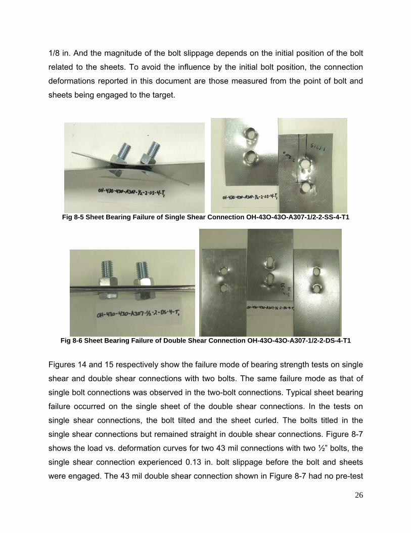
Fig 8-5 Sheet Bearing Failure of Single Shear Connection OH-43O-43O-A307-1/2-2-SS-4-T1
Fig 8-6 Sheet Bearing Failure of Double Shear Connection OH-43O-43O-A307-1/2-2-DS-4-T1
Figures 14 and 15 respectively show the failure mode of bearing strength tests on single
shear and double shear connections with two bolts. The same failure mode as that of
single bolt connections was observed in the two-bolt connections. Typical sheet bearing
failure occurred on the single sheet of the double shear connections. In the tests on
single shear connections, the bolt tilted and the sheet curled. The bolts titled in the
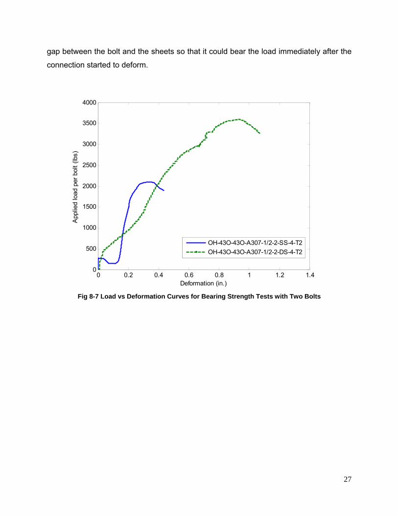
single shear connections but remained straight in double shear connections. Figure 8-7
shows the load vs. deformation curves for two 43 mil connections with two ½” bolts, the
single shear connection experienced 0.13 in. bolt slippage before the bolt and sheets
were engaged. The 43 mil double shear connection shown in Figure 8-7 had no pre-test
27
gap between the bolt and the sheets so that it could bear the load immediately after the
connection started to deform.
0 0.2 0.4 0.6 0.8 1 1.2 1.40
500
1000
1500
2000
2500
3000
3500
4000
Deformation (in.)
App
lied
load
per
bol
t (lb
s)
OH-43O-43O-A307-1/2-2-SS-4-T2OH-43O-43O-A307-1/2-2-DS-4-T2
Fig 8-7 Load vs Deformation Curves for Bearing Strength Tests with Two Bolts
28
Table 8-2 Test Results for Single Shear Connections with Oversized Hole, Single Bolt, e/d >1.5
No Specimen Label Nominal SHT(1)
Thickness(mil)
Nominal SHT(2)
Thickness(mil)
Bolt Dia. d (in.)
d/t Actual Fu(ksi)
Ptest (lbf) Δ (in.) Ptest/PNAS Ptest/PNEW
1 OH-118O-118O-A307-1/2-1-SS-4-T1 118 118 0.5 3.83 52.2 8499 0.360 1.11 1.16 2 OH-118O-118O-A307-1/2-1-SS-4-T2 118 118 0.5 3.83 52.2 8408 0.420 1.10 1.14 3 OH-68O-68O-A325-1/2-1-SS-4-T1 68 68 0.5 7.24 69.7 4685 0.682 0.86 0.92 4 OH-68O-68O-A325-1/2-1-SS-4-T2 68 68 0.5 7.24 69.7 4945 0.691 0.91 0.97 5 OH-68O-68O-A325-1/2-1-SS-4-T3 68 68 0.5 7.24 69.7 4649 0.382 0.86 0.91 6 OH-68O-68O-A307-1/2-1-SS-4-T1 68 68 0.5 7.24 69.7 3970 0.452 0.73 0.78 7 OH-68O-68O-A307-1/2-1-SS-4-T2 68 68 0.5 7.24 69.7 3925 0.547 0.72 0.77 8 OH-68O-68O-A307-1/2-1-SS-4-T3 68 68 0.5 7.24 69.7 4182 0.443 0.77 0.82 9 OH-43O-43O-A307-1/2-1-SS-4-T1 43 43 0.5 11.39 70.3 1904 0.206 0.58 0.77 10 OH-43O-43O-A307-1/2-1-SS-4-T2 43 43 0.5 11.39 70.3 1929 0.237 0.58 0.78 11 OH-43O-43O-A307-1/2-1-SS-4-T3 43 43 0.5 11.39 70.3 1885 0.200 0.57 0.76 12 OH-43O-43O-A307-1/4-1-SS-4-T1 43 43 0.25 5.69 70.3 1835 0.244 1.06 1.10 13 OH-43O-43O-A307-1/4-1-SS-4-T2 43 43 0.25 5.69 70.3 1894 0.275 1.09 1.14 14 OH-43O-43O-A307-1/4-1-SS-8-T1 43 43 0.25 5.69 70.3 1825 0.244 1.05 1.10 15 OH-43O-43O-A307-1/4-1-SS-8-T2 43 43 0.25 5.69 70.3 1725 0.276 0.99 1.04 16 OH-43O-43O-A307-1/4-1-SS-3-T1 43 43 0.25 5.69 70.3 1790 0.347 1.03 1.07 17 OH-43O-43O-A307-1/4-1-SS-3-T2 43 43 0.25 5.69 70.3 1823 0.319 1.05 1.09 18 OH-33O-33O-A307-1/2-1-SS-4-T1 33 33 0.5 13.85 54.1 1451 0.352 0.76 1.03 19 OH-33O-33O-A307-1/2-1-SS-4-T2 33 33 0.5 13.85 54.1 1444 0.566 0.75 1.02 20 OH-33O-33O-A307-1/4-1-SS-4-T1 33 33 0.25 6.93 54.1 1165 0.285 1.06 1.10 21 OH-33O-33O-A307-1/4-1-SS-4-T2 33 33 0.25 6.93 54.1 1213 0.281 1.10 1.15 22 OH-33O-33O-A307-1/4-1-SS-8-T1 33 33 0.25 6.93 54.1 1145 0.355 1.04 1.09 23 OH-33O-33O-A307-1/4-1-SS-8-T2 33 33 0.25 6.93 54.1 1232 0.397 1.12 1.17 24 OH-33O-33O-A307-1/4-1-SS-3-T1 33 33 0.25 6.93 54.1 1129 0.382 1.03 1.07 25 OH-33O-33O-A307-1/4-1-SS-3-T2 33 33 0.25 6.93 54.1 1136 0.321 1.03 1.08 26 OH-43O-33O-A307-1/2-1-SS-4-T1 43 33 0.5 13.85 54.1 1672 0.421 0.87 1.18 27 OH-43O-33O-A307-1/2-1-SS-4-T2 43 33 0.5 13.85 54.1 1635 0.424 0.85 1.16 28 OH-33O-33S-A307-1/2-1-SS-4-T1 33 33 0.5 13.85 54.1 1540 0.374 0.80 1.09 29 OH-33O-33S-A307-1/2-1-SS-4-T2 33 33 0.5 13.85 54.1 1548 0.304 0.81 1.09 30 OH-33O-33S-A307-1/2-1-SS-4-T2 33 33 0.5 13.85 54.1 1736 0.490 0.91 1.23 31 OH-30O-30O-A307-1/2-1-SS-4-T1 30 30 0.5 17.06 87.2 1620 0.319 0.74 0.97 32 OH-30O-30O-A307-1/2-1-SS-4-T2 30 30 0.5 17.06 87.2 1584 0.184 0.72 0.95 33 OH-39O-39O-A307-1/2-1-SS-4-T1 39 39 0.5 12.82 90.7 2423 0.373 0.67 0.91 34 OH-39O-39O-A307-1/2-1-SS-4-T2 39 39 0.5 12.82 90.7 2591 0.357 0.72 0.97
29
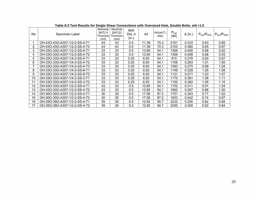
Table 8-3 Test Results for Single Shear Connections with Oversized Hole, Double Bolts, e/d >1.5
No Specimen Label Nominal SHT(1)
Thickness(mil)
Nominal SHT(2)
Thickness(mil)
Bolt Dia. d (in.)
d/t Actual Fu(ksi)
Ptest (lbf) Δ (in.) Ptest/PNAS Ptest/PNEW
1 OH-43O-43O-A307-1/2-2-SS-4-T1 43 43 0.5 11.39 70.3 2101 0.333 0.63 0.85 2 OH-43O-43O-A307-1/2-2-SS-4-T2 43 43 0.5 11.39 70.3 2153 0.380 0.65 0.87 3 OH-33O-33O-A307-1/2-2-SS-4-T1 33 33 0.5 13.85 54.1 1306 0.400 0.68 0.92 4 OH-33O-33O-A307-1/2-2-SS-4-T2 33 33 0.5 13.85 54.1 1309 0.408 0.68 0.93 5 OH-33O-33O-A307-1/4-2-SS-4-T1 33 33 0.25 6.93 54.1 915 0.278 0.83 0.87 6 OH-33O-33O-A307-1/4-2-SS-4-T2 33 33 0.25 6.93 54.1 1106 0.263 1.01 1.05 7 OH-33O-33O-A307-1/4-2-SS-4-T3 33 33 0.25 6.93 54.1 1093 0.275 0.99 1.04 8 OH-33O-33O-A307-1/4-2-SS-8-T1 33 33 0.25 6.93 54.1 1149 0.329 1.05 1.09 9 OH-33O-33O-A307-1/4-2-SS-8-T2 33 33 0.25 6.93 54.1 1131 0.271 1.03 1.07 10 OH-33O-33O-A307-1/4-2-SS-3-T1 33 33 0.25 6.93 54.1 1170 0.381 1.06 1.11 11 OH-33O-33O-A307-1/4-2-SS-3-T2 33 33 0.25 6.93 54.1 1155 0.362 1.05 1.10 12 OH-43O-33O-A307-1/2-2-SS-4-T1 43 33 0.5 13.85 54.1 1752 0.311 0.91 1.24 13 OH-43O-33O-A307-1/2-2-SS-4-T2 43 33 0.5 13.85 54.1 1692 0.267 0.88 1.20 14 OH-30O-30O-A307-1/2-2-SS-4-T1 30 30 0.5 17.06 87.2 1701 0.303 0.77 1.02 15 OH-30O-30O-A307-1/2-2-SS-4-T2 30 30 0.5 17.06 87.2 1633 0.442 0.74 0.97 16 OH-39O-39O-A307-1/2-2-SS-4-T1 39 39 0.5 12.82 90.7 2232 0.255 0.62 0.84 17 OH-39O-39O-A307-1/2-2-SS-4-T2 39 39 0.5 12.82 90.7 2250 0.409 0.62 0.84

30
Table 8-4 Test Results for Double Shear Connections with Oversized Hole, Single Bolt, e/d >1.5
No Specimen Label Nominal SHT(1)
Thickness(mil)
Nominal SHT(2)
Thickness(mil)
Bolt Dia. d (in.)
d/t Actual Fu(ksi)
Ptest (lbf) Δ (in.) Ptest/PNAS Ptest/PNEW
1 OH-68O-68O-A325-1/2-1-DS-4-T1 68 68 0.5 7.24 69.7 6824 0.664 0.71 0.86 2 OH-68O-68O-A325-1/2-1-DS-4-T2 68 68 0.5 7.24 69.7 6779 0.681 0.71 0.86 3 OH-43O-43O-A307-1/2-1-DS-4-T1 43 43 0.5 11.39 70.3 3933 0.471 0.67 1.02 4 OH-43O-43O-A307-1/2-1-DS-4-T2 43 43 0.5 11.39 70.3 3677 0.595 0.63 0.95 5 OH-33O-33O-A307-1/2-1-DS-4-T1 33 33 0.5 13.85 54.1 2637 0.606 0.78 1.20 6 OH-33O-33O-A307-1/2-1-DS-4-T2 33 33 0.5 13.85 54.1 2798 0.549 0.82 1.27 7 OH-33O-33O-A307-1/4-1-DS-4-T1 33 33 0.25 6.93 54.1 1888 0.345 0.97 1.15 8 OH-33O-33O-A307-1/4-1-DS-4-T2 33 33 0.25 6.93 54.1 1997 0.428 1.03 1.22 9 OH-33O-33O-A307-1/4-1-DS-8-T1 33 33 0.25 6.93 54.1 1912 0.396 0.98 1.17 10 OH-33O-33O-A307-1/4-1-DS-8-T2 33 33 0.25 6.93 54.1 1906 0.427 0.98 1.16 11 OH-33O-33O-A307-1/4-1-DS-3-T1 33 33 0.25 6.93 54.1 1768 0.409 0.91 1.08 12 OH-33O-33O-A307-1/4-1-DS-3-T2 33 33 0.25 6.93 54.1 1618 0.346 0.83 0.99 13 OH-30O-30O-A307-1/2-1-DS-4-T1 30 30 0.5 17.06 87.2 2380 0.401 0.61 0.91 14 OH-30O-30O-A307-1/2-1-DS-4-T2 30 30 0.5 17.06 87.2 2720 0.380 0.70 1.04 15 OH-30O-30O-A307-1/2-1-DS-4-T3 30 30 0.5 17.06 87.2 2548 0.466 0.65 0.98 16 OH-39O-39O-A307-1/2-1-DS-4-T1 39 39 0.5 12.82 90.7 3270 0.559 0.51 0.79 17 OH-39O-39O-A307-1/2-1-DS-4-T2 39 39 0.5 12.82 90.7 3335 0.675 0.52 0.80
31
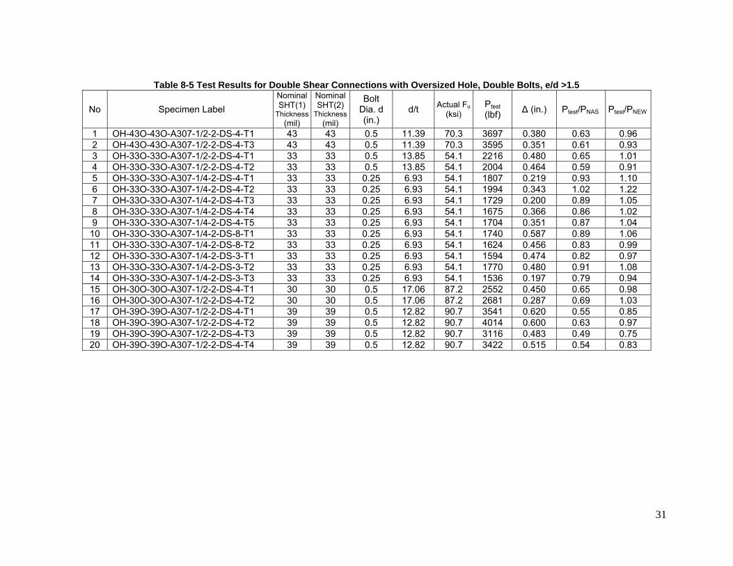
Table 8-5 Test Results for Double Shear Connections with Oversized Hole, Double Bolts, e/d >1.5
No Specimen Label Nominal SHT(1)
Thickness(mil)
Nominal SHT(2)
Thickness(mil)
Bolt Dia. d (in.)
d/t Actual Fu(ksi)
Ptest (lbf) Δ (in.) Ptest/PNAS Ptest/PNEW
1 OH-43O-43O-A307-1/2-2-DS-4-T1 43 43 0.5 11.39 70.3 3697 0.380 0.63 0.96 2 OH-43O-43O-A307-1/2-2-DS-4-T3 43 43 0.5 11.39 70.3 3595 0.351 0.61 0.93 3 OH-33O-33O-A307-1/2-2-DS-4-T1 33 33 0.5 13.85 54.1 2216 0.480 0.65 1.01 4 OH-33O-33O-A307-1/2-2-DS-4-T2 33 33 0.5 13.85 54.1 2004 0.464 0.59 0.91 5 OH-33O-33O-A307-1/4-2-DS-4-T1 33 33 0.25 6.93 54.1 1807 0.219 0.93 1.10 6 OH-33O-33O-A307-1/4-2-DS-4-T2 33 33 0.25 6.93 54.1 1994 0.343 1.02 1.22 7 OH-33O-33O-A307-1/4-2-DS-4-T3 33 33 0.25 6.93 54.1 1729 0.200 0.89 1.05 8 OH-33O-33O-A307-1/4-2-DS-4-T4 33 33 0.25 6.93 54.1 1675 0.366 0.86 1.02 9 OH-33O-33O-A307-1/4-2-DS-4-T5 33 33 0.25 6.93 54.1 1704 0.351 0.87 1.04 10 OH-33O-33O-A307-1/4-2-DS-8-T1 33 33 0.25 6.93 54.1 1740 0.587 0.89 1.06 11 OH-33O-33O-A307-1/4-2-DS-8-T2 33 33 0.25 6.93 54.1 1624 0.456 0.83 0.99 12 OH-33O-33O-A307-1/4-2-DS-3-T1 33 33 0.25 6.93 54.1 1594 0.474 0.82 0.97 13 OH-33O-33O-A307-1/4-2-DS-3-T2 33 33 0.25 6.93 54.1 1770 0.480 0.91 1.08 14 OH-33O-33O-A307-1/4-2-DS-3-T3 33 33 0.25 6.93 54.1 1536 0.197 0.79 0.94 15 OH-30O-30O-A307-1/2-2-DS-4-T1 30 30 0.5 17.06 87.2 2552 0.450 0.65 0.98 16 OH-30O-30O-A307-1/2-2-DS-4-T2 30 30 0.5 17.06 87.2 2681 0.287 0.69 1.03 17 OH-39O-39O-A307-1/2-2-DS-4-T1 39 39 0.5 12.82 90.7 3541 0.620 0.55 0.85 18 OH-39O-39O-A307-1/2-2-DS-4-T2 39 39 0.5 12.82 90.7 4014 0.600 0.63 0.97 19 OH-39O-39O-A307-1/2-2-DS-4-T3 39 39 0.5 12.82 90.7 3116 0.483 0.49 0.75 20 OH-39O-39O-A307-1/2-2-DS-4-T4 39 39 0.5 12.82 90.7 3422 0.515 0.54 0.83

32
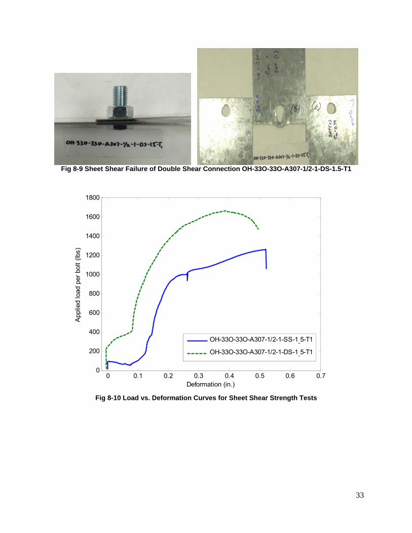
8.2.2 Sheet Shear Failure
The shear failure of the sheet (Type I) was investigated by tensile tests on connections
with e/d =1.5 and using one bolt. The test results are summarized in Tables 8-6 and 8-7,
where Ptest is the tested peak load per bolt and “Δ” is the connection deformation at the
peak load. Figure 8-8 and 8-9 respectively show the typical failure mode observed in the
shear strength tests on 33 mil single shear and double shear connections using one ½”
A307 bolt. It was found that the bolt was titled significantly in the single shear tests due
to the eccentric loading and the oversized hole dimension. As a result, the sheet warped
and piled up at bearing area next to the hole. A combined failure mode of shear and
bearing were achieved in the single shear tests, as shown in Figure 8-8. For the double
shear tests, typical shear failure was observed on the inside sheet, the sheet fractured
and deformed greatly at the hole edge. In the double shear tests the bolt remained
perpendicular to the sheets. Figure 8-10 shows the load vs. deformation curves for 33
mil connection tests in sheet shear failure mode, both tests demonstrated bolt slippage
of 0.1 in. Due to the tilting of the bolt, the single shear connection started losing stiffness
at earlier stage than the double shear connection did and finally failed at lower load
compared to that of the double shear connection.
Fig 8-8 Sheet Shear Failure of Single Shear Connection OH-33O-33O-A307-1/2-1-SS-1.5-T2
33
Fig 8-9 Sheet Shear Failure of Double Shear Connection OH-33O-33O-A307-1/2-1-DS-1.5-T1
0 0.1 0.2 0.3 0.4 0.5 0.6 0.70
200
400
600
800
1000
1200
1400
1600
1800
Deformation (in.)
App
lied
load
per
bol
t (lb
s)
OH-33O-33O-A307-1/2-1-SS-1-5-T1
OH-33O-33O-A307-1/2-1-DS-1-5-T1
Fig 8-10 Load vs. Deformation Curves for Sheet Shear Strength Tests
34
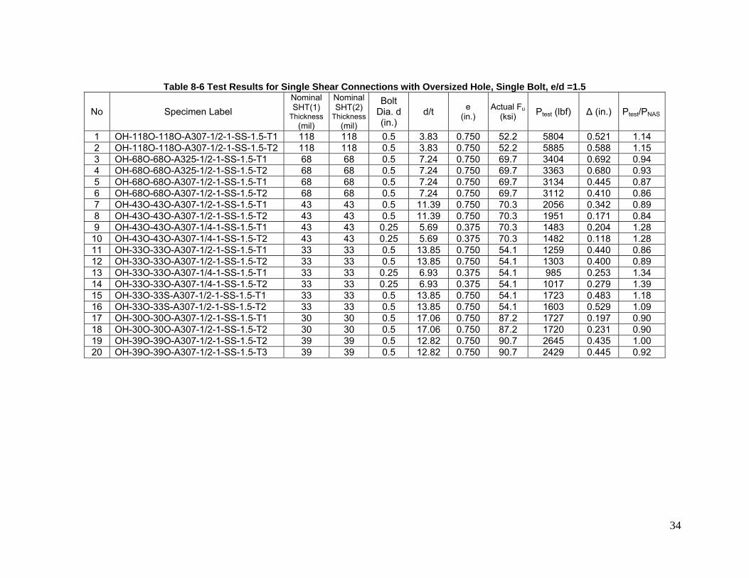
Table 8-6 Test Results for Single Shear Connections with Oversized Hole, Single Bolt, e/d =1.5
No Specimen Label Nominal SHT(1)
Thickness (mil)
Nominal SHT(2)
Thickness(mil)
Bolt Dia. d (in.)
d/t e (in.)
Actual Fu(ksi) Ptest (lbf) Δ (in.) Ptest/PNAS
1 OH-118O-118O-A307-1/2-1-SS-1.5-T1 118 118 0.5 3.83 0.750 52.2 5804 0.521 1.14 2 OH-118O-118O-A307-1/2-1-SS-1.5-T2 118 118 0.5 3.83 0.750 52.2 5885 0.588 1.15 3 OH-68O-68O-A325-1/2-1-SS-1.5-T1 68 68 0.5 7.24 0.750 69.7 3404 0.692 0.94 4 OH-68O-68O-A325-1/2-1-SS-1.5-T2 68 68 0.5 7.24 0.750 69.7 3363 0.680 0.93 5 OH-68O-68O-A307-1/2-1-SS-1.5-T1 68 68 0.5 7.24 0.750 69.7 3134 0.445 0.87 6 OH-68O-68O-A307-1/2-1-SS-1.5-T2 68 68 0.5 7.24 0.750 69.7 3112 0.410 0.86 7 OH-43O-43O-A307-1/2-1-SS-1.5-T1 43 43 0.5 11.39 0.750 70.3 2056 0.342 0.89 8 OH-43O-43O-A307-1/2-1-SS-1.5-T2 43 43 0.5 11.39 0.750 70.3 1951 0.171 0.84 9 OH-43O-43O-A307-1/4-1-SS-1.5-T1 43 43 0.25 5.69 0.375 70.3 1483 0.204 1.28 10 OH-43O-43O-A307-1/4-1-SS-1.5-T2 43 43 0.25 5.69 0.375 70.3 1482 0.118 1.28 11 OH-33O-33O-A307-1/2-1-SS-1.5-T1 33 33 0.5 13.85 0.750 54.1 1259 0.440 0.86 12 OH-33O-33O-A307-1/2-1-SS-1.5-T2 33 33 0.5 13.85 0.750 54.1 1303 0.400 0.89 13 OH-33O-33O-A307-1/4-1-SS-1.5-T1 33 33 0.25 6.93 0.375 54.1 985 0.253 1.34 14 OH-33O-33O-A307-1/4-1-SS-1.5-T2 33 33 0.25 6.93 0.375 54.1 1017 0.279 1.39 15 OH-33O-33S-A307-1/2-1-SS-1.5-T1 33 33 0.5 13.85 0.750 54.1 1723 0.483 1.18 16 OH-33O-33S-A307-1/2-1-SS-1.5-T2 33 33 0.5 13.85 0.750 54.1 1603 0.529 1.09 17 OH-30O-30O-A307-1/2-1-SS-1.5-T1 30 30 0.5 17.06 0.750 87.2 1727 0.197 0.90 18 OH-30O-30O-A307-1/2-1-SS-1.5-T2 30 30 0.5 17.06 0.750 87.2 1720 0.231 0.90 19 OH-39O-39O-A307-1/2-1-SS-1.5-T2 39 39 0.5 12.82 0.750 90.7 2645 0.435 1.00 20 OH-39O-39O-A307-1/2-1-SS-1.5-T3 39 39 0.5 12.82 0.750 90.7 2429 0.445 0.92
35
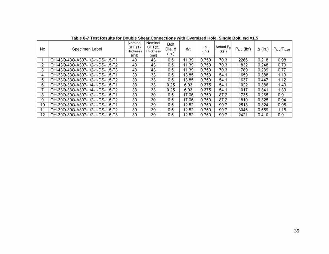
Table 8-7 Test Results for Double Shear Connections with Oversized Hole, Single Bolt, e/d =1.5
No Specimen Label Nominal SHT(1)
Thickness (mil)
Nominal SHT(2)
Thickness(mil)
Bolt Dia. d (in.)
d/t e (in.)
Actual Fu(ksi) Ptest (lbf) Δ (in.) Ptest/PNAS
1 OH-43O-43O-A307-1/2-1-DS-1.5-T1 43 43 0.5 11.39 0.750 70.3 2266 0.218 0.98 2 OH-43O-43O-A307-1/2-1-DS-1.5-T2 43 43 0.5 11.39 0.750 70.3 1832 0.248 0.79 3 OH-43O-43O-A307-1/2-1-DS-1.5-T3 43 43 0.5 11.39 0.750 70.3 1789 0.239 0.77 4 OH-33O-33O-A307-1/2-1-DS-1.5-T1 33 33 0.5 13.85 0.750 54.1 1659 0.388 1.13 5 OH-33O-33O-A307-1/2-1-DS-1.5-T2 33 33 0.5 13.85 0.750 54.1 1637 0.447 1.12 6 OH-33O-33O-A307-1/4-1-DS-1.5-T1 33 33 0.25 6.93 0.375 54.1 1022 0.386 1.40 7 OH-33O-33O-A307-1/4-1-DS-1.5-T2 33 33 0.25 6.93 0.375 54.1 1017 0.341 1.39 8 OH-30O-30O-A307-1/2-1-DS-1.5-T1 30 30 0.5 17.06 0.750 87.2 1735 0.265 0.91 9 OH-30O-30O-A307-1/2-1-DS-1.5-T2 30 30 0.5 17.06 0.750 87.2 1810 0.325 0.94 10 OH-39O-39O-A307-1/2-1-DS-1.5-T1 39 39 0.5 12.82 0.750 90.7 2518 0.324 0.95 11 OH-39O-39O-A307-1/2-1-DS-1.5-T2 39 39 0.5 12.82 0.750 90.7 3046 0.559 1.15 12 OH-39O-39O-A307-1/2-1-DS-1.5-T3 39 39 0.5 12.82 0.750 90.7 2421 0.410 0.91
36
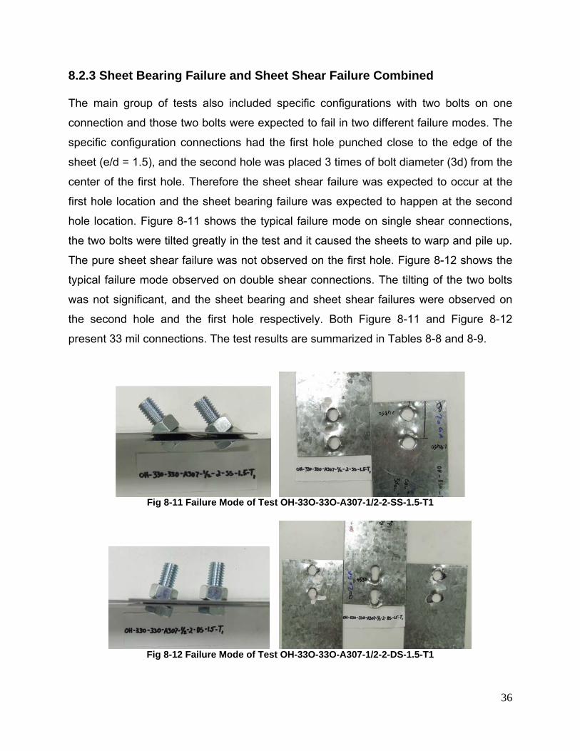
8.2.3 Sheet Bearing Failure and Sheet Shear Failure Combined
The main group of tests also included specific configurations with two bolts on one
connection and those two bolts were expected to fail in two different failure modes. The
specific configuration connections had the first hole punched close to the edge of the
sheet (e/d = 1.5), and the second hole was placed 3 times of bolt diameter (3d) from the
center of the first hole. Therefore the sheet shear failure was expected to occur at the
first hole location and the sheet bearing failure was expected to happen at the second
hole location. Figure 8-11 shows the typical failure mode on single shear connections,
the two bolts were tilted greatly in the test and it caused the sheets to warp and pile up.
The pure sheet shear failure was not observed on the first hole. Figure 8-12 shows the
typical failure mode observed on double shear connections. The tilting of the two bolts
was not significant, and the sheet bearing and sheet shear failures were observed on
the second hole and the first hole respectively. Both Figure 8-11 and Figure 8-12
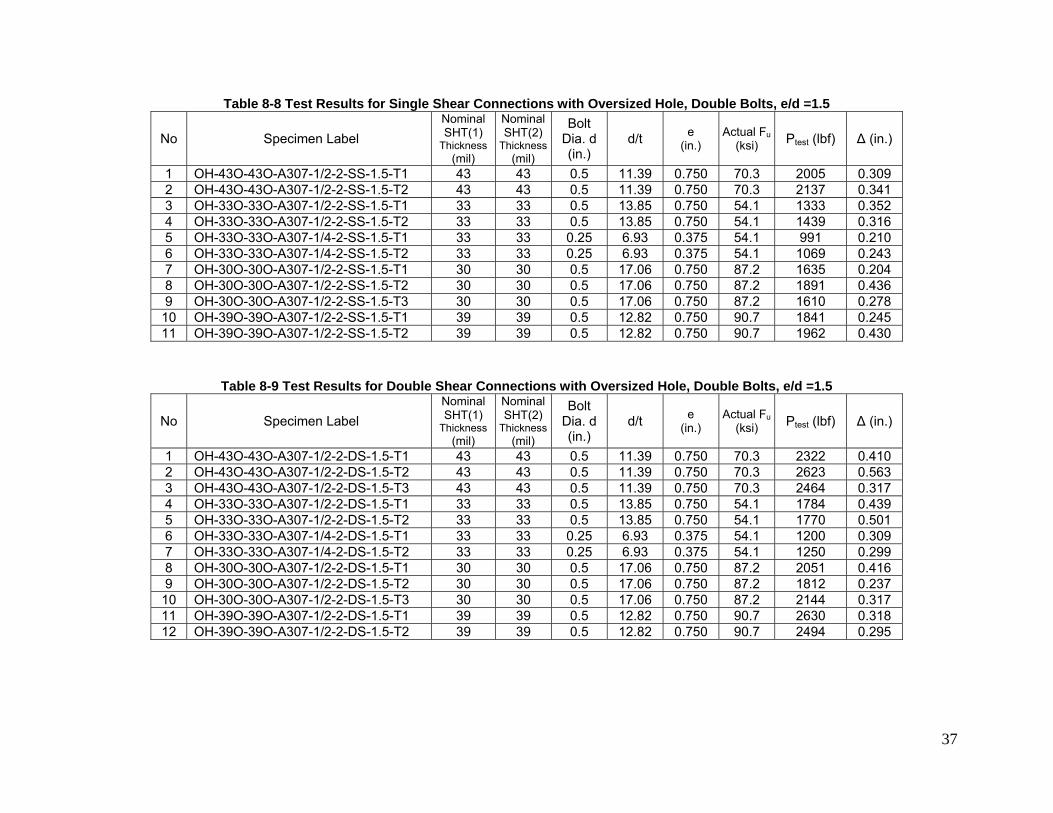
present 33 mil connections. The test results are summarized in Tables 8-8 and 8-9.
Fig 8-11 Failure Mode of Test OH-33O-33O-A307-1/2-2-SS-1.5-T1
Fig 8-12 Failure Mode of Test OH-33O-33O-A307-1/2-2-DS-1.5-T1
37
Table 8-8 Test Results for Single Shear Connections with Oversized Hole, Double Bolts, e/d =1.5
No Specimen Label Nominal SHT(1)
Thickness (mil)
Nominal SHT(2)
Thickness(mil)
Bolt Dia. d (in.)
d/t e (in.)
Actual Fu(ksi) Ptest (lbf) Δ (in.)
1 OH-43O-43O-A307-1/2-2-SS-1.5-T1 43 43 0.5 11.39 0.750 70.3 2005 0.309 2 OH-43O-43O-A307-1/2-2-SS-1.5-T2 43 43 0.5 11.39 0.750 70.3 2137 0.341 3 OH-33O-33O-A307-1/2-2-SS-1.5-T1 33 33 0.5 13.85 0.750 54.1 1333 0.352 4 OH-33O-33O-A307-1/2-2-SS-1.5-T2 33 33 0.5 13.85 0.750 54.1 1439 0.316 5 OH-33O-33O-A307-1/4-2-SS-1.5-T1 33 33 0.25 6.93 0.375 54.1 991 0.210 6 OH-33O-33O-A307-1/4-2-SS-1.5-T2 33 33 0.25 6.93 0.375 54.1 1069 0.243 7 OH-30O-30O-A307-1/2-2-SS-1.5-T1 30 30 0.5 17.06 0.750 87.2 1635 0.204 8 OH-30O-30O-A307-1/2-2-SS-1.5-T2 30 30 0.5 17.06 0.750 87.2 1891 0.436 9 OH-30O-30O-A307-1/2-2-SS-1.5-T3 30 30 0.5 17.06 0.750 87.2 1610 0.278 10 OH-39O-39O-A307-1/2-2-SS-1.5-T1 39 39 0.5 12.82 0.750 90.7 1841 0.245 11 OH-39O-39O-A307-1/2-2-SS-1.5-T2 39 39 0.5 12.82 0.750 90.7 1962 0.430
Table 8-9 Test Results for Double Shear Connections with Oversized Hole, Double Bolts, e/d =1.5
No Specimen Label Nominal SHT(1)
Thickness (mil)
Nominal SHT(2)
Thickness(mil)
Bolt Dia. d (in.)
d/t e (in.)
Actual Fu(ksi) Ptest (lbf) Δ (in.)
1 OH-43O-43O-A307-1/2-2-DS-1.5-T1 43 43 0.5 11.39 0.750 70.3 2322 0.410 2 OH-43O-43O-A307-1/2-2-DS-1.5-T2 43 43 0.5 11.39 0.750 70.3 2623 0.563 3 OH-43O-43O-A307-1/2-2-DS-1.5-T3 43 43 0.5 11.39 0.750 70.3 2464 0.317 4 OH-33O-33O-A307-1/2-2-DS-1.5-T1 33 33 0.5 13.85 0.750 54.1 1784 0.439 5 OH-33O-33O-A307-1/2-2-DS-1.5-T2 33 33 0.5 13.85 0.750 54.1 1770 0.501 6 OH-33O-33O-A307-1/4-2-DS-1.5-T1 33 33 0.25 6.93 0.375 54.1 1200 0.309 7 OH-33O-33O-A307-1/4-2-DS-1.5-T2 33 33 0.25 6.93 0.375 54.1 1250 0.299 8 OH-30O-30O-A307-1/2-2-DS-1.5-T1 30 30 0.5 17.06 0.750 87.2 2051 0.416 9 OH-30O-30O-A307-1/2-2-DS-1.5-T2 30 30 0.5 17.06 0.750 87.2 1812 0.237 10 OH-30O-30O-A307-1/2-2-DS-1.5-T3 30 30 0.5 17.06 0.750 87.2 2144 0.317 11 OH-39O-39O-A307-1/2-2-DS-1.5-T1 39 39 0.5 12.82 0.750 90.7 2630 0.318 12 OH-39O-39O-A307-1/2-2-DS-1.5-T2 39 39 0.5 12.82 0.750 90.7 2494 0.295

38
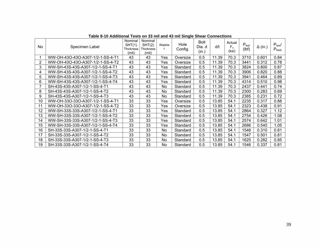
8.3 TENSILE TESTS ON BOLTED CONNECTIONS WITHOUT WASHIERS ON OVERSIZED HOLES (ADDITIONAL GROUP)
In addition to the main test group, a series of additional tests on a small range of
configurations were also performed. The purpose of the additional group of tests was to
make direct comparison on the bearing strength between the connections with
oversized holes and connections with standard holes, with or without washers. All the
additional tests were on single shear connections with single A307 ½” bolt and e/d = 4.
The following parameters are included in test configurations.
1. Oversized hole, with washers
2. Standard hole, with washers
3. Standard hole, without washers
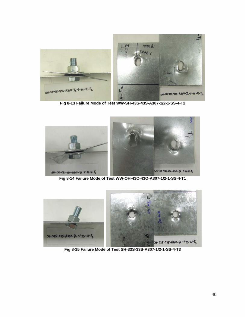
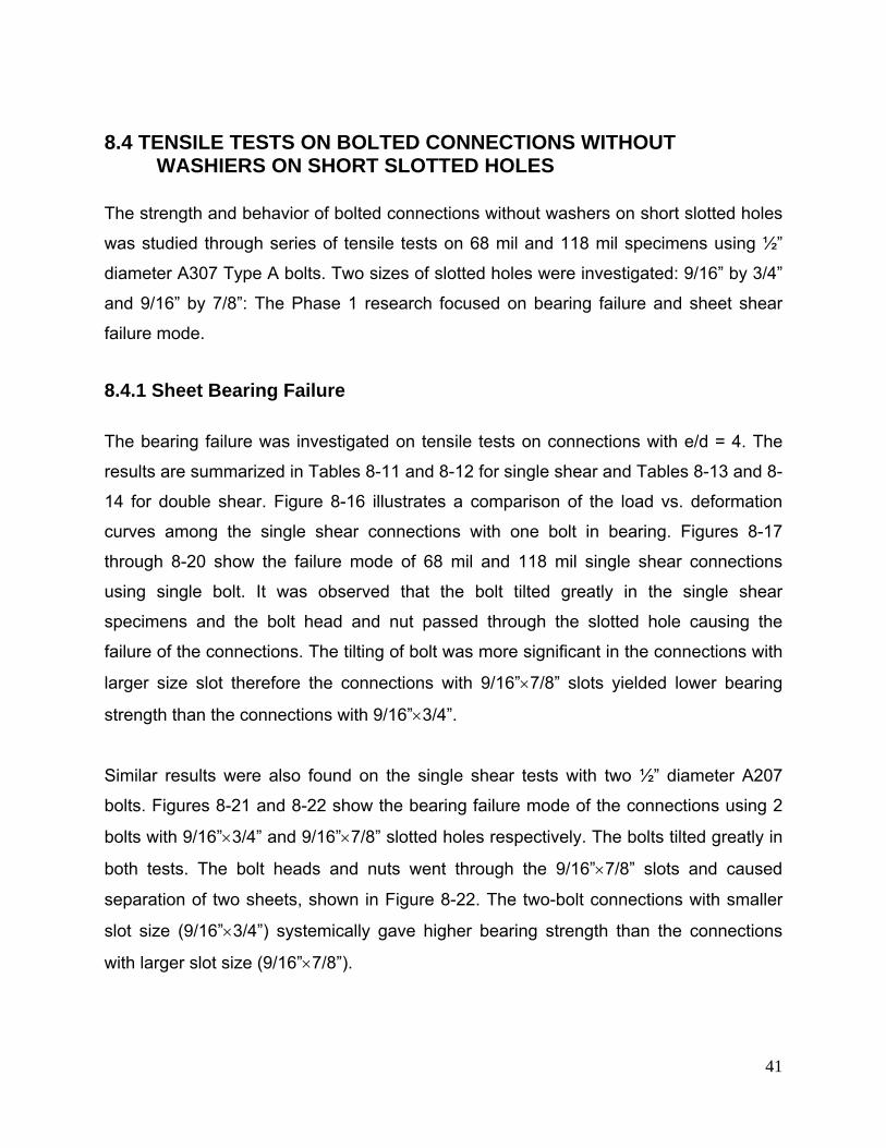
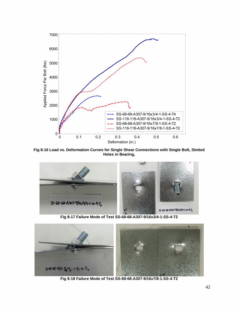
The results of these additional tests are listed in Table 8-10. Figures 8-13 and 8-14
respectively shows the failure mode of the 43 mil connections with washers on standard
hole and oversized hole. Compared to the connections without washers, the
connections with washers demonstrated less tilting of the bolt and the larger hole
deformation which resulted in higher bearing strength. Figure 8-15 shows the failure
mode of a 43 mil connection without washer on standard hole. The bolt tilted but the nut
and bolt head did not go through the hole and the hole was less deformed compared to
tests with washers.
39
Table 8-10 Additional Tests on 33 mil and 43 mil Single Shear Connections
No Specimen Label Nominal SHT(1)
Thickness(mil)
Nominal SHT(2)
Thickness(mil)
Washer
Hole Config.
Bolt Dia. d (in.)
d/t Actual
Fu (ksi)
Ptest (lbf) Δ (in.) Ptest/
PNAS
1 WW-OH-43O-43O-A307-1/2-1-SS-4-T1 43 43 Yes Oversize 0.5 11.39 70.3 3710 0.601 0.84 2 WW-OH-43O-43O-A307-1/2-1-SS-4-T2 43 43 Yes Oversize 0.5 11.39 70.3 3441 0.312 0.78 3 WW-SH-43S-43S-A307-1/2-1-SS-4-T1 43 43 Yes Standard 0.5 11.39 70.3 3824 0.800 0.87 4 WW-SH-43S-43S-A307-1/2-1-SS-4-T2 43 43 Yes Standard 0.5 11.39 70.3 3906 0.820 0.88 5 WW-SH-43S-43S-A307-1/2-1-SS-4-T3 43 43 Yes Standard 0.5 11.39 70.3 3941 0.464 0.89 6 WW-SH-43S-43S-A307-1/2-1-SS-4-T4 43 43 Yes Standard 0.5 11.39 70.3 4314 0.510 0.98 7 SH-43S-43S-A307-1/2-1-SS-4-T1 43 43 No Standard 0.5 11.39 70.3 2437 0.441 0.74 8 SH-43S-43S-A307-1/2-1-SS-4-T2 43 43 No Standard 0.5 11.39 70.3 2300 0.283 0.69 9 SH-43S-43S-A307-1/2-1-SS-4-T3 43 43 No Standard 0.5 11.39 70.3 2385 0.231 0.72 10 WW-OH-33O-33O-A307-1/2-1-SS-4-T1 33 33 Yes Oversize 0.5 13.85 54.1 2235 0.317 0.88 11 WW-OH-33O-33O-A307-1/2-1-SS-4-T2 33 33 Yes Oversize 0.5 13.85 54.1 2323 0.438 0.91 12 WW-SH-33S-33S-A307-1/2-1-SS-4-T1 33 33 Yes Standard 0.5 13.85 54.1 2864 0.327 1.12 13 WW-SH-33S-33S-A307-1/2-1-SS-4-T2 33 33 Yes Standard 0.5 13.85 54.1 2754 0.426 1.08 14 WW-SH-33S-33S-A307-1/2-1-SS-4-T3 33 33 Yes Standard 0.5 13.85 54.1 2574 0.642 1.01 15 WW-SH-33S-33S-A307-1/2-1-SS-4-T4 33 33 Yes Standard 0.5 13.85 54.1 2686 0.540 1.05 16 SH-33S-33S-A307-1/2-1-SS-4-T1 33 33 No Standard 0.5 13.85 54.1 1546 0.310 0.81 17 SH-33S-33S-A307-1/2-1-SS-4-T2 33 33 No Standard 0.5 13.85 54.1 1547 0.501 0.81 18 SH-33S-33S-A307-1/2-1-SS-4-T3 33 33 No Standard 0.5 13.85 54.1 1625 0.282 0.85 19 SH-33S-33S-A307-1/2-1-SS-4-T4 33 33 No Standard 0.5 13.85 54.1 1546 0.337 0.81
40
Fig 8-13 Failure Mode of Test WW-SH-43S-43S-A307-1/2-1-SS-4-T2
Fig 8-14 Failure Mode of Test WW-OH-43O-43O-A307-1/2-1-SS-4-T1
Fig 8-15 Failure Mode of Test SH-33S-33S-A307-1/2-1-SS-4-T3
41
8.4 TENSILE TESTS ON BOLTED CONNECTIONS WITHOUT WASHIERS ON SHORT SLOTTED HOLES
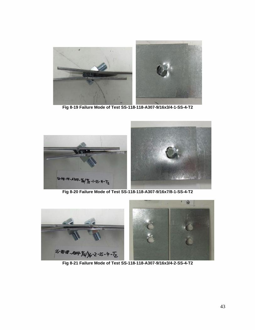
The strength and behavior of bolted connections without washers on short slotted holes
was studied through series of tensile tests on 68 mil and 118 mil specimens using ½”
diameter A307 Type A bolts. Two sizes of slotted holes were investigated: 9/16” by 3/4”
and 9/16” by 7/8”: The Phase 1 research focused on bearing failure and sheet shear
failure mode.
8.4.1 Sheet Bearing Failure
The bearing failure was investigated on tensile tests on connections with e/d = 4. The
results are summarized in Tables 8-11 and 8-12 for single shear and Tables 8-13 and 8-
14 for double shear. Figure 8-16 illustrates a comparison of the load vs. deformation
curves among the single shear connections with one bolt in bearing. Figures 8-17
through 8-20 show the failure mode of 68 mil and 118 mil single shear connections
using single bolt. It was observed that the bolt tilted greatly in the single shear
specimens and the bolt head and nut passed through the slotted hole causing the
failure of the connections. The tilting of bolt was more significant in the connections with
larger size slot therefore the connections with 9/16”×7/8” slots yielded lower bearing
strength than the connections with 9/16”×3/4”.
Similar results were also found on the single shear tests with two ½” diameter A207
bolts. Figures 8-21 and 8-22 show the bearing failure mode of the connections using 2
bolts with 9/16”×3/4” and 9/16”×7/8” slotted holes respectively. The bolts tilted greatly in
both tests. The bolt heads and nuts went through the 9/16”×7/8” slots and caused
separation of two sheets, shown in Figure 8-22. The two-bolt connections with smaller
slot size (9/16”×3/4”) systemically gave higher bearing strength than the connections
with larger slot size (9/16”×7/8”).
42
0 0.1 0.2 0.3 0.4 0.5 0.60
1000
2000
3000
4000
5000
6000
7000
Deformation (in.)
App
lied
Forc
e P
er B
olt (
lbs)
SS-68-68-A307-9/16x3/4-1-SS-4-T4SS-118-118-A307-9/16x3/4-1-SS-4-T2SS-68-68-A307-9/16x7/8-1-SS-4-T2SS-118-118-A307-9/16x7/8-1-SS-4-T2
Fig 8-16 Load vs. Deformation Curves for Single Shear Connections with Single Bolt, Slotted
Holes in Bearing,
Fig 8-17 Failure Mode of Test SS-68-68-A307-9/16x3/4-1-SS-4-T2
Fig 8-18 Failure Mode of Test SS-68-68-A307-9/16x7/8-1-SS-4-T2
43
Fig 8-19 Failure Mode of Test SS-118-118-A307-9/16x3/4-1-SS-4-T2
Fig 8-20 Failure Mode of Test SS-118-118-A307-9/16x7/8-1-SS-4-T2
Fig 8-21 Failure Mode of Test SS-118-118-A307-9/16x3/4-2-SS-4-T2
44
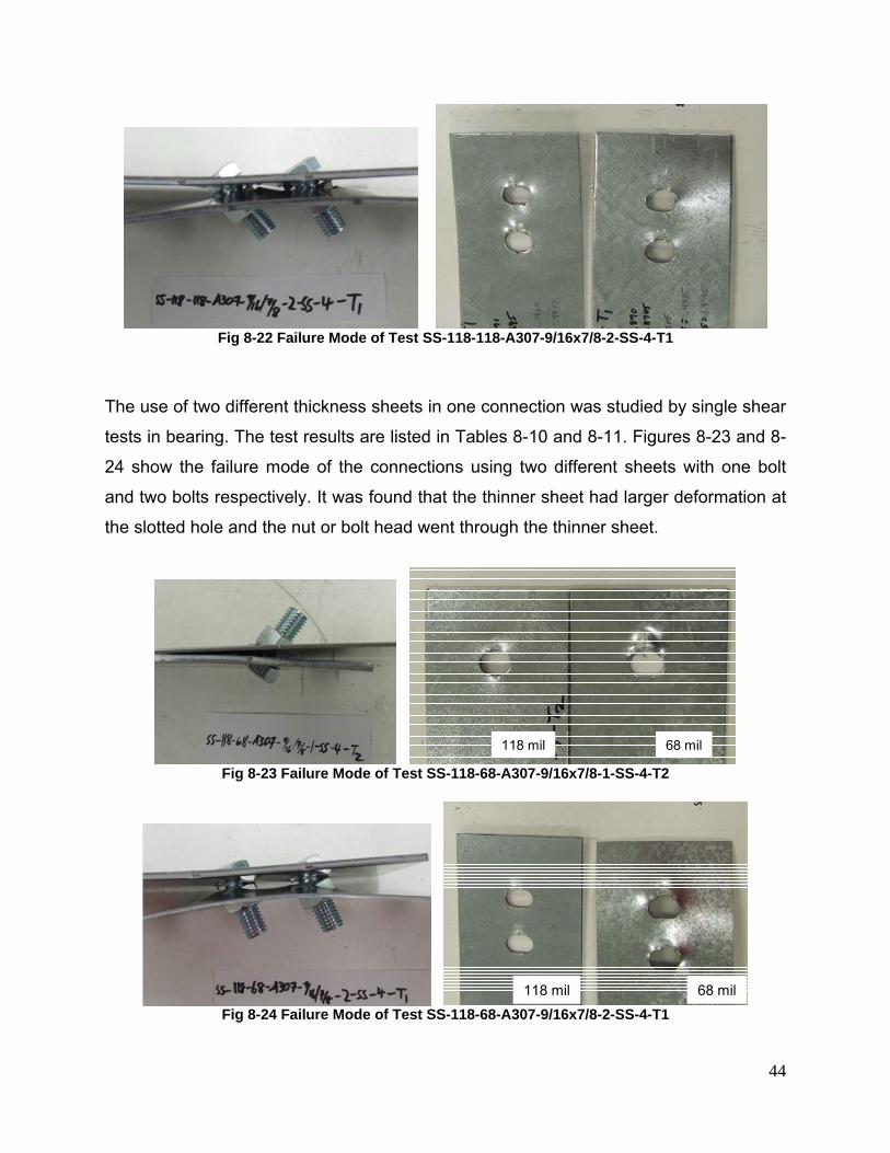
Fig 8-22 Failure Mode of Test SS-118-118-A307-9/16x7/8-2-SS-4-T1
The use of two different thickness sheets in one connection was studied by single shear
tests in bearing. The test results are listed in Tables 8-10 and 8-11. Figures 8-23 and 8-
24 show the failure mode of the connections using two different sheets with one bolt
and two bolts respectively. It was found that the thinner sheet had larger deformation at
the slotted hole and the nut or bolt head went through the thinner sheet.
68 mil118 mil
Fig 8-23 Failure Mode of Test SS-118-68-A307-9/16x7/8-1-SS-4-T2
68 mil118 mil Fig 8-24 Failure Mode of Test SS-118-68-A307-9/16x7/8-2-SS-4-T1
45
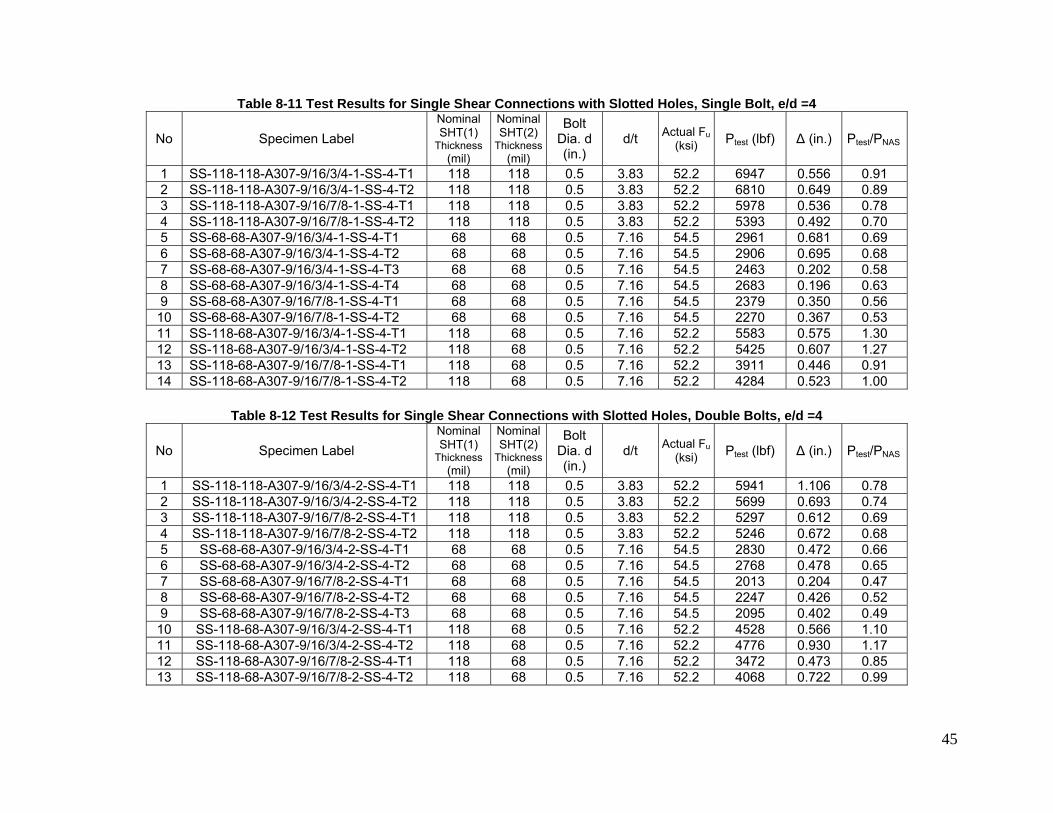
Table 8-11 Test Results for Single Shear Connections with Slotted Holes, Single Bolt, e/d =4
No Specimen Label Nominal SHT(1)
Thickness (mil)
Nominal SHT(2)
Thickness(mil)
Bolt Dia. d (in.)
d/t Actual Fu(ksi) Ptest (lbf) Δ (in.) Ptest/PNAS
1 SS-118-118-A307-9/16/3/4-1-SS-4-T1 118 118 0.5 3.83 52.2 6947 0.556 0.91 2 SS-118-118-A307-9/16/3/4-1-SS-4-T2 118 118 0.5 3.83 52.2 6810 0.649 0.89 3 SS-118-118-A307-9/16/7/8-1-SS-4-T1 118 118 0.5 3.83 52.2 5978 0.536 0.78 4 SS-118-118-A307-9/16/7/8-1-SS-4-T2 118 118 0.5 3.83 52.2 5393 0.492 0.70 5 SS-68-68-A307-9/16/3/4-1-SS-4-T1 68 68 0.5 7.16 54.5 2961 0.681 0.69 6 SS-68-68-A307-9/16/3/4-1-SS-4-T2 68 68 0.5 7.16 54.5 2906 0.695 0.68 7 SS-68-68-A307-9/16/3/4-1-SS-4-T3 68 68 0.5 7.16 54.5 2463 0.202 0.58 8 SS-68-68-A307-9/16/3/4-1-SS-4-T4 68 68 0.5 7.16 54.5 2683 0.196 0.63 9 SS-68-68-A307-9/16/7/8-1-SS-4-T1 68 68 0.5 7.16 54.5 2379 0.350 0.56 10 SS-68-68-A307-9/16/7/8-1-SS-4-T2 68 68 0.5 7.16 54.5 2270 0.367 0.53 11 SS-118-68-A307-9/16/3/4-1-SS-4-T1 118 68 0.5 7.16 52.2 5583 0.575 1.30 12 SS-118-68-A307-9/16/3/4-1-SS-4-T2 118 68 0.5 7.16 52.2 5425 0.607 1.27 13 SS-118-68-A307-9/16/7/8-1-SS-4-T1 118 68 0.5 7.16 52.2 3911 0.446 0.91 14 SS-118-68-A307-9/16/7/8-1-SS-4-T2 118 68 0.5 7.16 52.2 4284 0.523 1.00
Table 8-12 Test Results for Single Shear Connections with Slotted Holes, Double Bolts, e/d =4
No Specimen Label Nominal SHT(1)
Thickness (mil)
Nominal SHT(2)
Thickness(mil)
Bolt Dia. d (in.)
d/t Actual Fu(ksi) Ptest (lbf) Δ (in.) Ptest/PNAS
1 SS-118-118-A307-9/16/3/4-2-SS-4-T1 118 118 0.5 3.83 52.2 5941 1.106 0.78 2 SS-118-118-A307-9/16/3/4-2-SS-4-T2 118 118 0.5 3.83 52.2 5699 0.693 0.74 3 SS-118-118-A307-9/16/7/8-2-SS-4-T1 118 118 0.5 3.83 52.2 5297 0.612 0.69 4 SS-118-118-A307-9/16/7/8-2-SS-4-T2 118 118 0.5 3.83 52.2 5246 0.672 0.68 5 SS-68-68-A307-9/16/3/4-2-SS-4-T1 68 68 0.5 7.16 54.5 2830 0.472 0.66 6 SS-68-68-A307-9/16/3/4-2-SS-4-T2 68 68 0.5 7.16 54.5 2768 0.478 0.65 7 SS-68-68-A307-9/16/7/8-2-SS-4-T1 68 68 0.5 7.16 54.5 2013 0.204 0.47 8 SS-68-68-A307-9/16/7/8-2-SS-4-T2 68 68 0.5 7.16 54.5 2247 0.426 0.52 9 SS-68-68-A307-9/16/7/8-2-SS-4-T3 68 68 0.5 7.16 54.5 2095 0.402 0.49 10 SS-118-68-A307-9/16/3/4-2-SS-4-T1 118 68 0.5 7.16 52.2 4528 0.566 1.10 11 SS-118-68-A307-9/16/3/4-2-SS-4-T2 118 68 0.5 7.16 52.2 4776 0.930 1.17 12 SS-118-68-A307-9/16/7/8-2-SS-4-T1 118 68 0.5 7.16 52.2 3472 0.473 0.85 13 SS-118-68-A307-9/16/7/8-2-SS-4-T2 118 68 0.5 7.16 52.2 4068 0.722 0.99
46
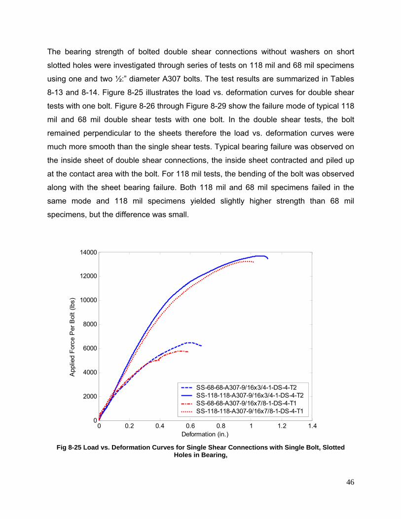
The bearing strength of bolted double shear connections without washers on short
slotted holes were investigated through series of tests on 118 mil and 68 mil specimens
using one and two ½:” diameter A307 bolts. The test results are summarized in Tables
8-13 and 8-14. Figure 8-25 illustrates the load vs. deformation curves for double shear
tests with one bolt. Figure 8-26 through Figure 8-29 show the failure mode of typical 118
mil and 68 mil double shear tests with one bolt. In the double shear tests, the bolt
remained perpendicular to the sheets therefore the load vs. deformation curves were
much more smooth than the single shear tests. Typical bearing failure was observed on
the inside sheet of double shear connections, the inside sheet contracted and piled up
at the contact area with the bolt. For 118 mil tests, the bending of the bolt was observed
along with the sheet bearing failure. Both 118 mil and 68 mil specimens failed in the
same mode and 118 mil specimens yielded slightly higher strength than 68 mil
specimens, but the difference was small.
0 0.2 0.4 0.6 0.8 1 1.2 1.40
2000
4000
6000
8000
10000
12000
14000
Deformation (in.)
App
lied
Forc
e P
er B
olt (
lbs)
SS-68-68-A307-9/16x3/4-1-DS-4-T2SS-118-118-A307-9/16x3/4-1-DS-4-T2SS-68-68-A307-9/16x7/8-1-DS-4-T1SS-118-118-A307-9/16x7/8-1-DS-4-T1
Fig 8-25 Load vs. Deformation Curves for Single Shear Connections with Single Bolt, Slotted
Holes in Bearing,
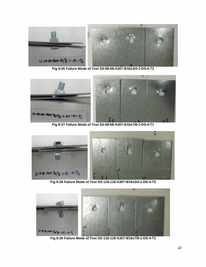
47
Fig 8-26 Failure Mode of Test SS-68-68-A307-9/16x3/4-1-DS-4-T2
Fig 8-27 Failure Mode of Test SS-68-68-A307-9/16x7/8-1-DS-4-T1
Fig 8-28 Failure Mode of Test SS-118-118-A307-9/16x3/4-1-DS-4-T2
Fig 8-29 Failure Mode of Test SS-118-118-A307-9/16x7/8-1-DS-4-T1
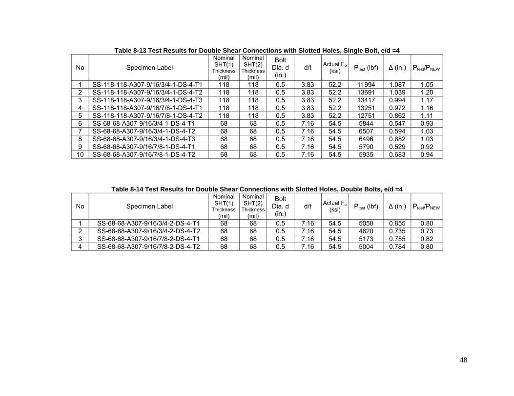
48
Table 8-13 Test Results for Double Shear Connections with Slotted Holes, Single Bolt, e/d =4
No Specimen Label Nominal SHT(1)
Thickness (mil)
Nominal SHT(2)
Thickness(mil)
Bolt Dia. d (in.)
d/t Actual Fu(ksi) Ptest (lbf) Δ (in.) Ptest/PNEW
1 SS-118-118-A307-9/16/3/4-1-DS-4-T1 118 118 0.5 3.83 52.2 11994 1.087 1.05 2 SS-118-118-A307-9/16/3/4-1-DS-4-T2 118 118 0.5 3.83 52.2 13691 1.039 1.20 3 SS-118-118-A307-9/16/3/4-1-DS-4-T3 118 118 0.5 3.83 52.2 13417 0.994 1.17 4 SS-118-118-A307-9/16/7/8-1-DS-4-T1 118 118 0.5 3.83 52.2 13251 0.972 1.16 5 SS-118-118-A307-9/16/7/8-1-DS-4-T2 118 118 0.5 3.83 52.2 12751 0.862 1.11 6 SS-68-68-A307-9/16/3/4-1-DS-4-T1 68 68 0.5 7.16 54.5 5844 0.547 0.93 7 SS-68-68-A307-9/16/3/4-1-DS-4-T2 68 68 0.5 7.16 54.5 6507 0.594 1.03 8 SS-68-68-A307-9/16/3/4-1-DS-4-T3 68 68 0.5 7.16 54.5 6496 0.682 1.03 9 SS-68-68-A307-9/16/7/8-1-DS-4-T1 68 68 0.5 7.16 54.5 5790 0.529 0.92 10 SS-68-68-A307-9/16/7/8-1-DS-4-T2 68 68 0.5 7.16 54.5 5935 0.683 0.94
Table 8-14 Test Results for Double Shear Connections with Slotted Holes, Double Bolts, e/d =4
No Specimen Label Nominal SHT(1)
Thickness (mil)
Nominal SHT(2)
Thickness(mil)
Bolt Dia. d (in.)
d/t Actual Fu(ksi) Ptest (lbf) Δ (in.) Ptest/PNEW
1 SS-68-68-A307-9/16/3/4-2-DS-4-T1 68 68 0.5 7.16 54.5 5058 0.855 0.80 2 SS-68-68-A307-9/16/3/4-2-DS-4-T2 68 68 0.5 7.16 54.5 4620 0.735 0.73 3 SS-68-68-A307-9/16/7/8-2-DS-4-T1 68 68 0.5 7.16 54.5 5173 0.755 0.82 4 SS-68-68-A307-9/16/7/8-2-DS-4-T2 68 68 0.5 7.16 54.5 5004 0.784 0.80
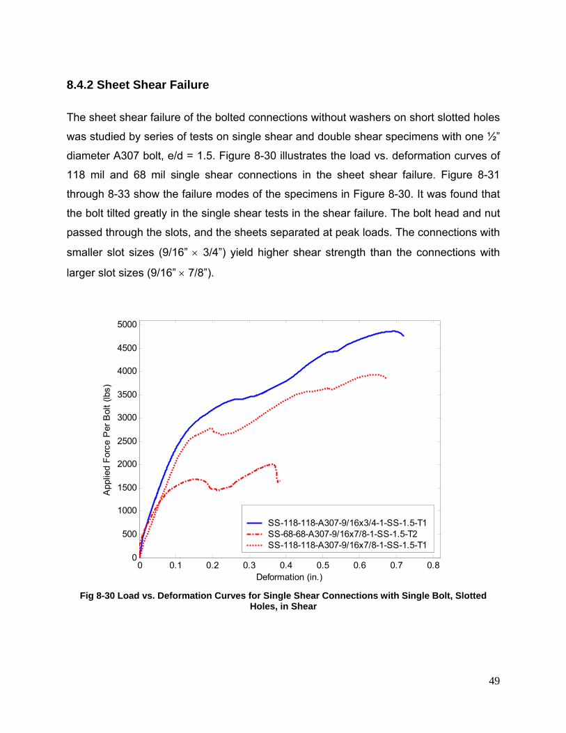
49
8.4.2 Sheet Shear Failure
The sheet shear failure of the bolted connections without washers on short slotted holes
was studied by series of tests on single shear and double shear specimens with one ½”
diameter A307 bolt, e/d = 1.5. Figure 8-30 illustrates the load vs. deformation curves of
118 mil and 68 mil single shear connections in the sheet shear failure. Figure 8-31
through 8-33 show the failure modes of the specimens in Figure 8-30. It was found that
the bolt tilted greatly in the single shear tests in the shear failure. The bolt head and nut
passed through the slots, and the sheets separated at peak loads. The connections with
smaller slot sizes (9/16” × 3/4”) yield higher shear strength than the connections with
larger slot sizes (9/16” × 7/8”).
0 0.1 0.2 0.3 0.4 0.5 0.6 0.7 0.80
500
1000
1500
2000
2500
3000
3500
4000
4500
5000
Deformation (in.)
App
lied
Forc
e P
er B
olt (
lbs)
SS-118-118-A307-9/16x3/4-1-SS-1.5-T1SS-68-68-A307-9/16x7/8-1-SS-1.5-T2SS-118-118-A307-9/16x7/8-1-SS-1.5-T1
Fig 8-30 Load vs. Deformation Curves for Single Shear Connections with Single Bolt, Slotted
Holes, in Shear
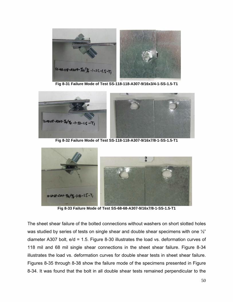
50
Fig 8-31 Failure Mode of Test SS-118-118-A307-9/16x3/4-1-SS-1.5-T1
Fig 8-32 Failure Mode of Test SS-118-118-A307-9/16x7/8-1-SS-1.5-T1
Fig 8-33 Failure Mode of Test SS-68-68-A307-9/16x7/8-1-SS-1.5-T1
The sheet shear failure of the bolted connections without washers on short slotted holes
was studied by series of tests on single shear and double shear specimens with one ½”
diameter A307 bolt, e/d = 1.5. Figure 8-30 illustrates the load vs. deformation curves of
118 mil and 68 mil single shear connections in the sheet shear failure. Figure 8-34
illustrates the load vs. deformation curves for double shear tests in sheet shear failure.
Figures 8-35 through 8-38 show the failure mode of the specimens presented in Figure
8-34. It was found that the bolt in all double shear tests remained perpendicular to the
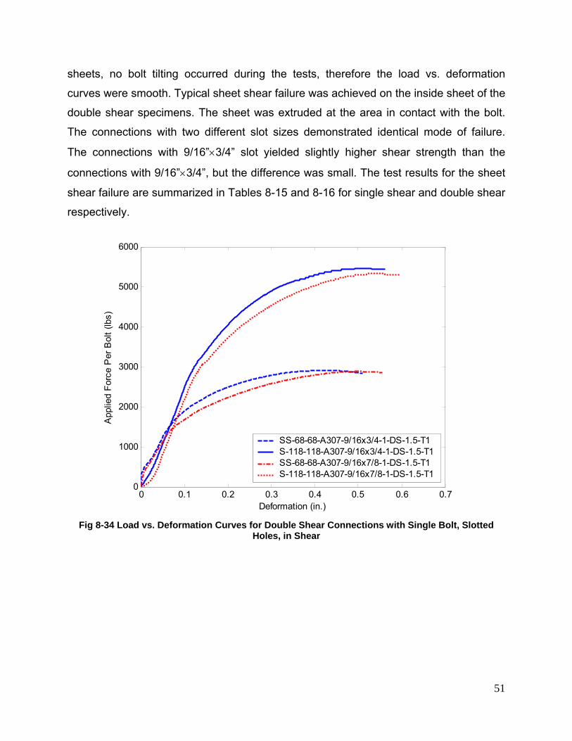
51
sheets, no bolt tilting occurred during the tests, therefore the load vs. deformation
curves were smooth. Typical sheet shear failure was achieved on the inside sheet of the
double shear specimens. The sheet was extruded at the area in contact with the bolt.
The connections with two different slot sizes demonstrated identical mode of failure.
The connections with 9/16”×3/4” slot yielded slightly higher shear strength than the
connections with 9/16”×3/4”, but the difference was small. The test results for the sheet
shear failure are summarized in Tables 8-15 and 8-16 for single shear and double shear
respectively.
0 0.1 0.2 0.3 0.4 0.5 0.6 0.70
1000
2000
3000
4000
5000
6000
Deformation (in.)
App
lied
Forc
e P
er B
olt (
lbs)
SS-68-68-A307-9/16x3/4-1-DS-1.5-T1S-118-118-A307-9/16x3/4-1-DS-1.5-T1SS-68-68-A307-9/16x7/8-1-DS-1.5-T1S-118-118-A307-9/16x7/8-1-DS-1.5-T1
Fig 8-34 Load vs. Deformation Curves for Double Shear Connections with Single Bolt, Slotted
Holes, in Shear
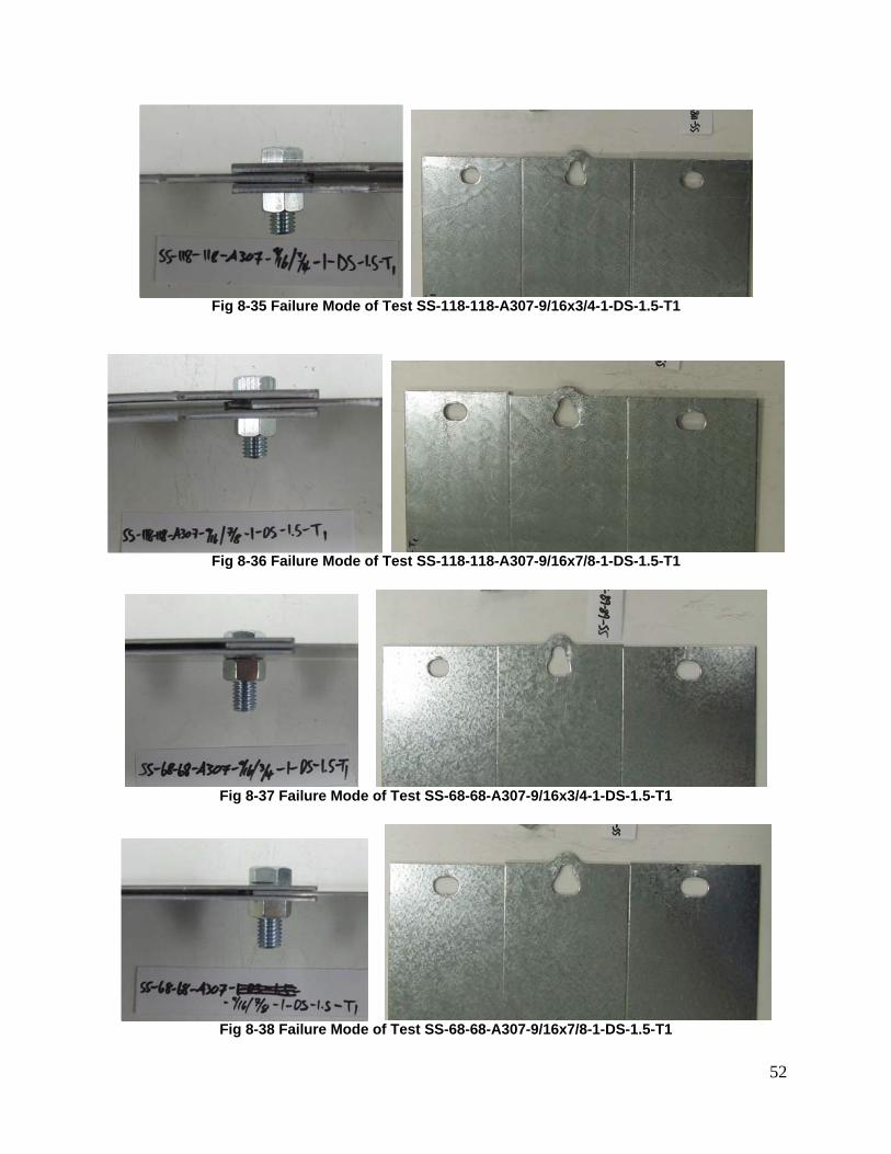
52
Fig 8-35 Failure Mode of Test SS-118-118-A307-9/16x3/4-1-DS-1.5-T1
Fig 8-36 Failure Mode of Test SS-118-118-A307-9/16x7/8-1-DS-1.5-T1
Fig 8-37 Failure Mode of Test SS-68-68-A307-9/16x3/4-1-DS-1.5-T1
Fig 8-38 Failure Mode of Test SS-68-68-A307-9/16x7/8-1-DS-1.5-T1
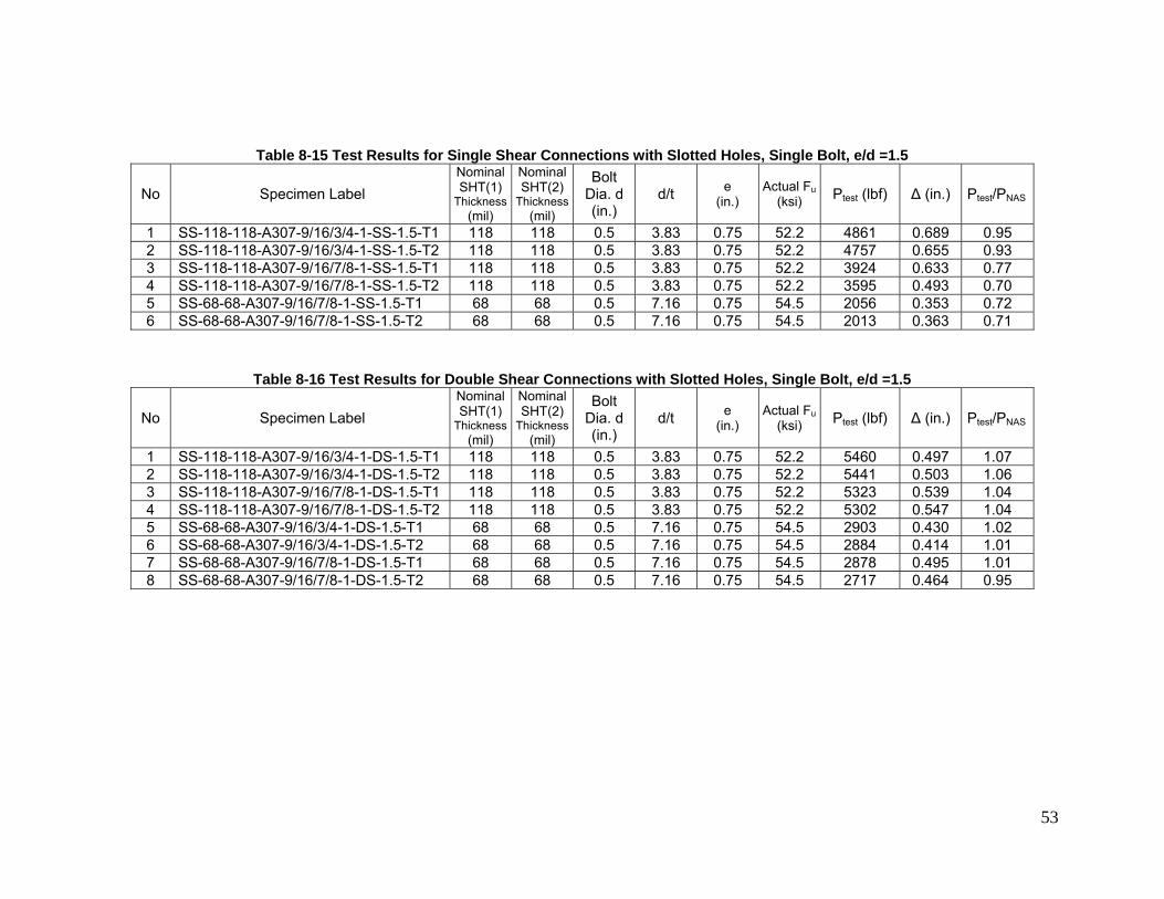
53
Table 8-15 Test Results for Single Shear Connections with Slotted Holes, Single Bolt, e/d =1.5
No Specimen Label Nominal SHT(1)
Thickness(mil)
Nominal SHT(2)
Thickness(mil)
Bolt Dia. d (in.)
d/t e (in.)
Actual Fu(ksi) Ptest (lbf) Δ (in.) Ptest/PNAS
1 SS-118-118-A307-9/16/3/4-1-SS-1.5-T1 118 118 0.5 3.83 0.75 52.2 4861 0.689 0.95 2 SS-118-118-A307-9/16/3/4-1-SS-1.5-T2 118 118 0.5 3.83 0.75 52.2 4757 0.655 0.93 3 SS-118-118-A307-9/16/7/8-1-SS-1.5-T1 118 118 0.5 3.83 0.75 52.2 3924 0.633 0.77 4 SS-118-118-A307-9/16/7/8-1-SS-1.5-T2 118 118 0.5 3.83 0.75 52.2 3595 0.493 0.70 5 SS-68-68-A307-9/16/7/8-1-SS-1.5-T1 68 68 0.5 7.16 0.75 54.5 2056 0.353 0.72 6 SS-68-68-A307-9/16/7/8-1-SS-1.5-T2 68 68 0.5 7.16 0.75 54.5 2013 0.363 0.71
Table 8-16 Test Results for Double Shear Connections with Slotted Holes, Single Bolt, e/d =1.5
No Specimen Label Nominal SHT(1)
Thickness(mil)
Nominal SHT(2)
Thickness(mil)
Bolt Dia. d (in.)
d/t e (in.)
Actual Fu(ksi) Ptest (lbf) Δ (in.) Ptest/PNAS
1 SS-118-118-A307-9/16/3/4-1-DS-1.5-T1 118 118 0.5 3.83 0.75 52.2 5460 0.497 1.07 2 SS-118-118-A307-9/16/3/4-1-DS-1.5-T2 118 118 0.5 3.83 0.75 52.2 5441 0.503 1.06 3 SS-118-118-A307-9/16/7/8-1-DS-1.5-T1 118 118 0.5 3.83 0.75 52.2 5323 0.539 1.04 4 SS-118-118-A307-9/16/7/8-1-DS-1.5-T2 118 118 0.5 3.83 0.75 52.2 5302 0.547 1.04 5 SS-68-68-A307-9/16/3/4-1-DS-1.5-T1 68 68 0.5 7.16 0.75 54.5 2903 0.430 1.02 6 SS-68-68-A307-9/16/3/4-1-DS-1.5-T2 68 68 0.5 7.16 0.75 54.5 2884 0.414 1.01 7 SS-68-68-A307-9/16/7/8-1-DS-1.5-T1 68 68 0.5 7.16 0.75 54.5 2878 0.495 1.01 8 SS-68-68-A307-9/16/7/8-1-DS-1.5-T2 68 68 0.5 7.16 0.75 54.5 2717 0.464 0.95
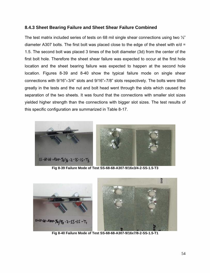
54
8.4.3 Sheet Bearing Failure and Sheet Shear Failure Combined
The test matrix included series of tests on 68 mil single shear connections using two ½”
diameter A307 bolts. The first bolt was placed close to the edge of the sheet with e/d =
1.5. The second bolt was placed 3 times of the bolt diameter (3d) from the center of the
first bolt hole. Therefore the sheet shear failure was expected to occur at the first hole
location and the sheet bearing failure was expected to happen at the second hole
location. Figures 8-39 and 8-40 show the typical failure mode on single shear
connections with 9/16”×3/4” slots and 9/16”×7/8” slots respectively. The bolts were tilted
greatly in the tests and the nut and bolt head went through the slots which caused the
separation of the two sheets. It was found that the connections with smaller slot sizes
yielded higher strength than the connections with bigger slot sizes. The test results of
this specific configuration are summarized in Table 8-17.
Fig 8-39 Failure Mode of Test SS-68-68-A307-9/16x3/4-2-SS-1.5-T3
Fig 8-40 Failure Mode of Test SS-68-68-A307-9/16x7/8-2-SS-1.5-T1
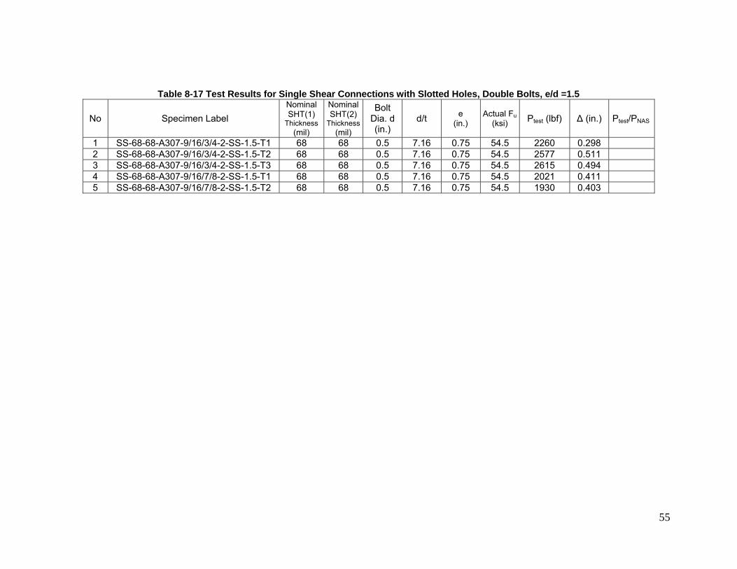
55
Table 8-17 Test Results for Single Shear Connections with Slotted Holes, Double Bolts, e/d =1.5
No Specimen Label Nominal SHT(1)
Thickness (mil)
Nominal SHT(2)
Thickness(mil)
Bolt Dia. d (in.)
d/t e (in.)
Actual Fu(ksi) Ptest (lbf) Δ (in.) Ptest/PNAS
1 SS-68-68-A307-9/16/3/4-2-SS-1.5-T1 68 68 0.5 7.16 0.75 54.5 2260 0.298 2 SS-68-68-A307-9/16/3/4-2-SS-1.5-T2 68 68 0.5 7.16 0.75 54.5 2577 0.511 3 SS-68-68-A307-9/16/3/4-2-SS-1.5-T3 68 68 0.5 7.16 0.75 54.5 2615 0.494 4 SS-68-68-A307-9/16/7/8-2-SS-1.5-T1 68 68 0.5 7.16 0.75 54.5 2021 0.411 5 SS-68-68-A307-9/16/7/8-2-SS-1.5-T2 68 68 0.5 7.16 0.75 54.5 1930 0.403
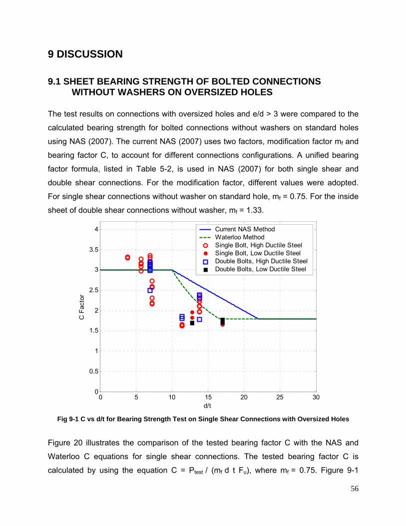
56
9 DISCUSSION
9.1 SHEET BEARING STRENGTH OF BOLTED CONNECTIONS WITHOUT WASHERS ON OVERSIZED HOLES
The test results on connections with oversized holes and e/d > 3 were compared to the
calculated bearing strength for bolted connections without washers on standard holes
using NAS (2007). The current NAS (2007) uses two factors, modification factor mf and
bearing factor C, to account for different connections configurations. A unified bearing
factor formula, listed in Table 5-2, is used in NAS (2007) for both single shear and
double shear connections. For the modification factor, different values were adopted.
For single shear connections without washer on standard hole, mf = 0.75. For the inside
sheet of double shear connections without washer, mf = 1.33.
0 5 10 15 20 25 300
0.5
1
1.5
2
2.5
3
3.5
4
d/t
C F
acto
r
Current NAS MethodWaterloo MethodSingle Bolt, High Ductile SteelSingle Bolt, Low Ductile SteelDouble Bolts, High Ductile SteelDouble Bolts, Low Ductile Steel
Fig 9-1 C vs d/t for Bearing Strength Test on Single Shear Connections with Oversized Holes
Figure 20 illustrates the comparison of the tested bearing factor C with the NAS and
Waterloo C equations for single shear connections. The tested bearing factor C is
calculated by using the equation C = Ptest / (mf d t Fu), where mf = 0.75. Figure 9-1
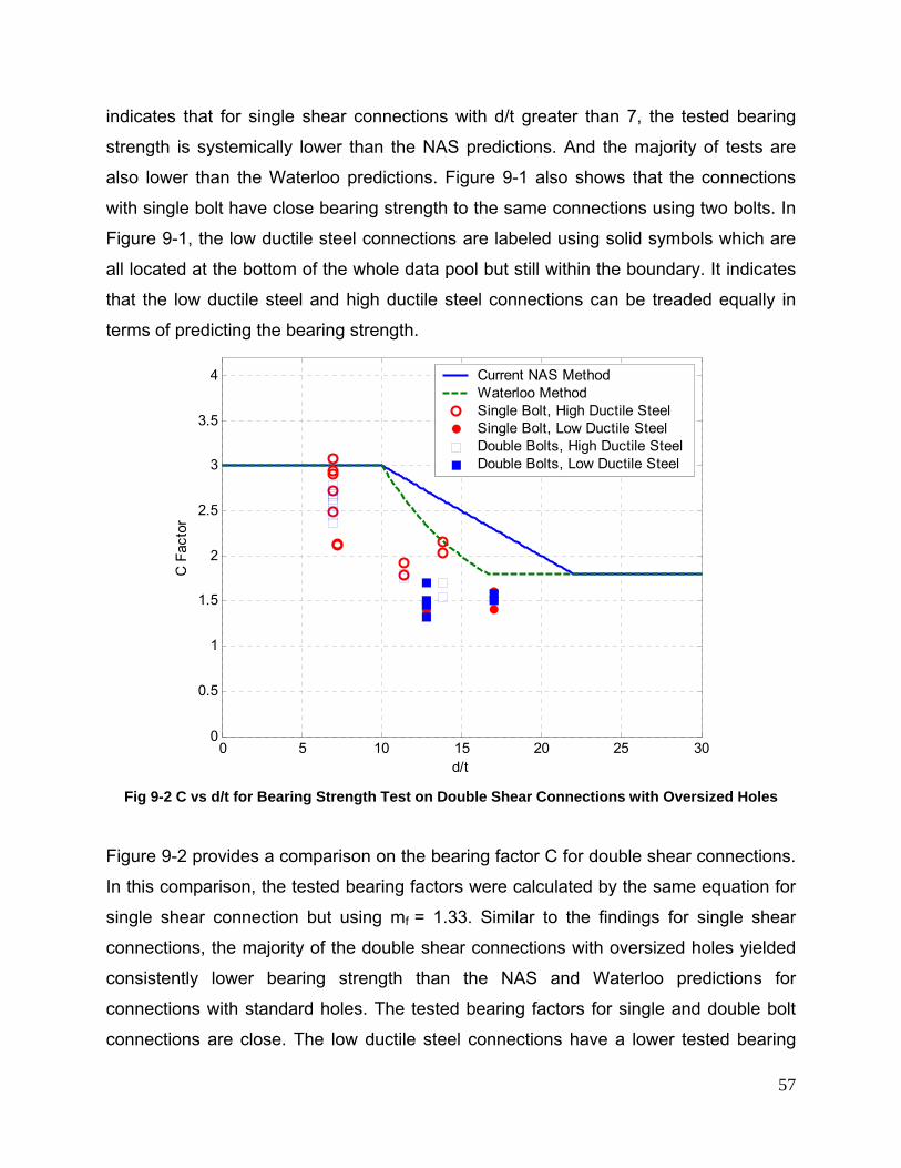
57
indicates that for single shear connections with d/t greater than 7, the tested bearing
strength is systemically lower than the NAS predictions. And the majority of tests are
also lower than the Waterloo predictions. Figure 9-1 also shows that the connections
with single bolt have close bearing strength to the same connections using two bolts. In
Figure 9-1, the low ductile steel connections are labeled using solid symbols which are
all located at the bottom of the whole data pool but still within the boundary. It indicates
that the low ductile steel and high ductile steel connections can be treaded equally in
terms of predicting the bearing strength.
0 5 10 15 20 25 300
0.5
1
1.5
2
2.5
3
3.5
4
d/t
C F
acto
r
Current NAS MethodWaterloo MethodSingle Bolt, High Ductile SteelSingle Bolt, Low Ductile SteelDouble Bolts, High Ductile SteelDouble Bolts, Low Ductile Steel
Fig 9-2 C vs d/t for Bearing Strength Test on Double Shear Connections with Oversized Holes
Figure 9-2 provides a comparison on the bearing factor C for double shear connections.
In this comparison, the tested bearing factors were calculated by the same equation for
single shear connection but using mf = 1.33. Similar to the findings for single shear
connections, the majority of the double shear connections with oversized holes yielded
consistently lower bearing strength than the NAS and Waterloo predictions for
connections with standard holes. The tested bearing factors for single and double bolt
connections are close. The low ductile steel connections have a lower tested bearing
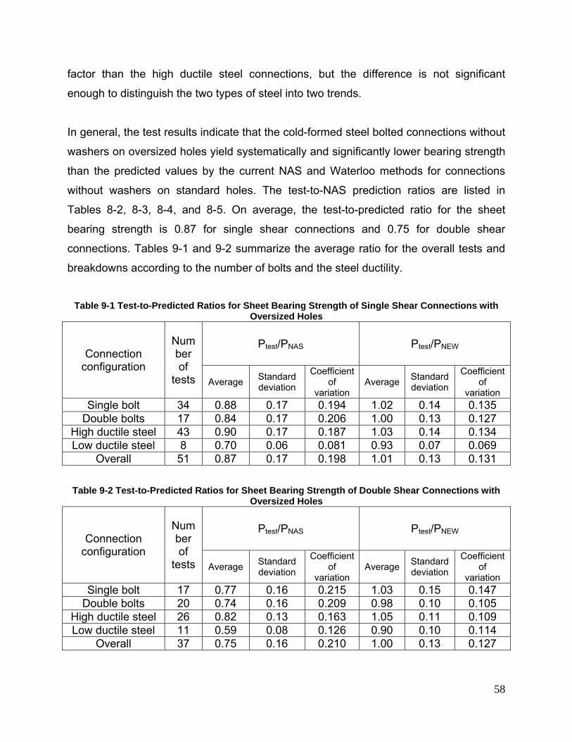
58
factor than the high ductile steel connections, but the difference is not significant
enough to distinguish the two types of steel into two trends.
In general, the test results indicate that the cold-formed steel bolted connections without
washers on oversized holes yield systematically and significantly lower bearing strength
than the predicted values by the current NAS and Waterloo methods for connections
without washers on standard holes. The test-to-NAS prediction ratios are listed in
Tables 8-2, 8-3, 8-4, and 8-5. On average, the test-to-predicted ratio for the sheet
bearing strength is 0.87 for single shear connections and 0.75 for double shear
connections. Tables 9-1 and 9-2 summarize the average ratio for the overall tests and
breakdowns according to the number of bolts and the steel ductility.
Table 9-1 Test-to-Predicted Ratios for Sheet Bearing Strength of Single Shear Connections with
Oversized Holes
Connection configuration
Number of
tests
Ptest/PNAS Ptest/PNEW
Average Standard deviation
Coefficient of
variation Average Standard
deviation
Coefficient of
variation Single bolt 34 0.88 0.17 0.194 1.02 0.14 0.135
Double bolts 17 0.84 0.17 0.206 1.00 0.13 0.127 High ductile steel 43 0.90 0.17 0.187 1.03 0.14 0.134 Low ductile steel 8 0.70 0.06 0.081 0.93 0.07 0.069
Overall 51 0.87 0.17 0.198 1.01 0.13 0.131 Table 9-2 Test-to-Predicted Ratios for Sheet Bearing Strength of Double Shear Connections with
Oversized Holes
Connection configuration
Number of
tests
Ptest/PNAS Ptest/PNEW
Average Standard deviation
Coefficient of
variation Average Standard
deviation
Coefficient of
variation Single bolt 17 0.77 0.16 0.215 1.03 0.15 0.147
Double bolts 20 0.74 0.16 0.209 0.98 0.10 0.105 High ductile steel 26 0.82 0.13 0.163 1.05 0.11 0.109 Low ductile steel 11 0.59 0.08 0.126 0.90 0.10 0.114
Overall 37 0.75 0.16 0.210 1.00 0.13 0.127
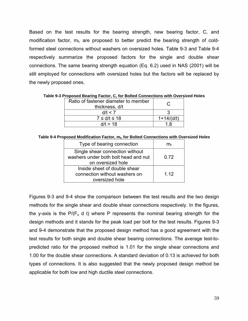
59
Based on the test results for the bearing strength, new bearing factor, C, and
modification factor, mf, are proposed to better predict the bearing strength of cold-
formed steel connections without washers on oversized holes. Table 9-3 and Table 9-4
respectively summarize the proposed factors for the single and double shear
connections. The same bearing strength equation (Eq. 6.2) used in NAS (2001) will be
still employed for connections with oversized holes but the factors will be replaced by
the newly proposed ones.
Table 9-3 Proposed Bearing Factor, C, for Bolted Connections with Oversized Holes
Ratio of fastener diameter to member thickness, d/t C
d/t < 7 3 7 ≤ d/t ≤ 18 1+14/(d/t)
d/t > 18 1.8
Table 9-4 Proposed Modification Factor, mf, for Bolted Connections with Oversized Holes
Type of bearing connection mf Single shear connection without
washers under both bolt head and nut on oversized hole
0.72
Inside sheet of double shear connection without washers on
oversized hole 1.12
Figures 9-3 and 9-4 show the comparison between the test results and the two design
methods for the single shear and double shear connections respectively. In the figures,
the y-axis is the P/(Fu d t) where P represents the nominal bearing strength for the
design methods and it stands for the peak load per bolt for the test results. Figures 9-3
and 9-4 demonstrate that the proposed design method has a good agreement with the
test results for both single and double shear bearing connections. The average test-to-
predicted ratio for the proposed method is 1.01 for the single shear connections and
1.00 for the double shear connections. A standard deviation of 0.13 is achieved for both
types of connections. It is also suggested that the newly proposed design method be
applicable for both low and high ductile steel connections.
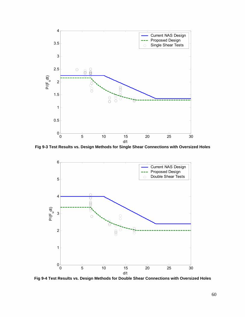
60
0 5 10 15 20 25 300
0.5
1
1.5
2
2.5
3
3.5
4
d/t
P/(F
udt)
Current NAS DesignProposed DesignSingle Shear Tests
Fig 9-3 Test Results vs. Design Methods for Single Shear Connections with Oversized Holes
0 5 10 15 20 25 300
1
2
3
4
5
6
d/t
P/(F
udt)
Current NAS DesignProposed DesignDouble Shear Tests
Fig 9-4 Test Results vs. Design Methods for Double Shear Connections with Oversized Holes
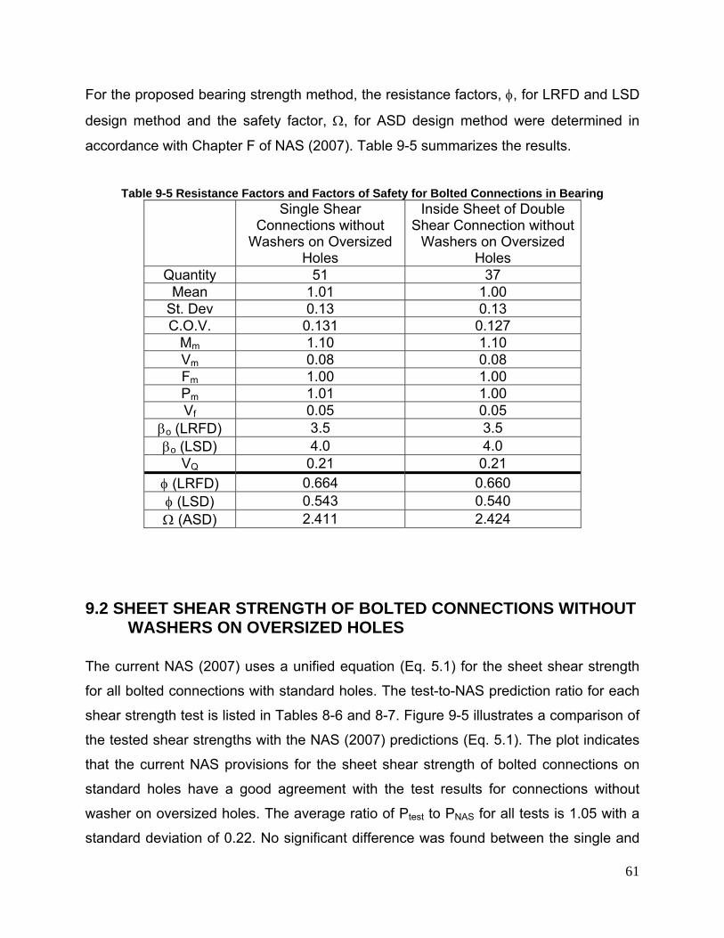
61
For the proposed bearing strength method, the resistance factors, φ, for LRFD and LSD
design method and the safety factor, Ω, for ASD design method were determined in
accordance with Chapter F of NAS (2007). Table 9-5 summarizes the results.
Table 9-5 Resistance Factors and Factors of Safety for Bolted Connections in Bearing
Single Shear Connections without
Washers on Oversized Holes
Inside Sheet of Double Shear Connection without
Washers on Oversized Holes
Quantity 51 37 Mean 1.01 1.00
St. Dev 0.13 0.13 C.O.V. 0.131 0.127
Mm 1.10 1.10 Vm 0.08 0.08 Fm 1.00 1.00 Pm 1.01 1.00 Vf 0.05 0.05
βo (LRFD) 3.5 3.5 βo (LSD) 4.0 4.0
VQ 0.21 0.21 φ (LRFD) 0.664 0.660 φ (LSD) 0.543 0.540 Ω (ASD) 2.411 2.424
9.2 SHEET SHEAR STRENGTH OF BOLTED CONNECTIONS WITHOUT WASHERS ON OVERSIZED HOLES
The current NAS (2007) uses a unified equation (Eq. 5.1) for the sheet shear strength
for all bolted connections with standard holes. The test-to-NAS prediction ratio for each
shear strength test is listed in Tables 8-6 and 8-7. Figure 9-5 illustrates a comparison of
the tested shear strengths with the NAS (2007) predictions (Eq. 5.1). The plot indicates
that the current NAS provisions for the sheet shear strength of bolted connections on
standard holes have a good agreement with the test results for connections without
washer on oversized holes. The average ratio of Ptest to PNAS for all tests is 1.05 with a
standard deviation of 0.22. No significant difference was found between the single and
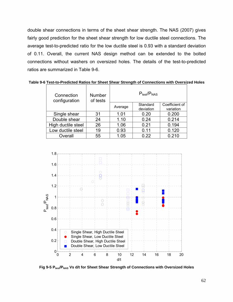
62
double shear connections in terms of the sheet shear strength. The NAS (2007) gives
fairly good prediction for the sheet shear strength for low ductile steel connections. The
average test-to-predicted ratio for the low ductile steel is 0.93 with a standard deviation
of 0.11. Overall, the current NAS design method can be extended to the bolted
connections without washers on oversized holes. The details of the test-to-predicted
ratios are summarized in Table 9-6.
Table 9-6 Test-to-Predicted Ratios for Sheet Shear Strength of Connections with Oversized Holes
Connection configuration
Number of tests
Ptest/PNAS
Average Standard deviation
Coefficient of variation
Single shear 31 1.01 0.20 0.200 Double shear 24 1.10 0.24 0.214
High ductile steel 26 1.06 0.21 0.194 Low ductile steel 19 0.93 0.11 0.120
Overall 55 1.05 0.22 0.210
0 2 4 6 8 10 12 14 16 18 200
0.2
0.4
0.6
0.8
1
1.2
1.4
1.6
1.8
d/t
Pte
st/P
NAS
Single Shear, High Ductile SteelSingle Shear, Low Ductile SteelDouble Shear, High Ductile SteelDouble Shear, Low Ductile Steel
Fig 9-5 Ptest/PNAS Vs d/t for Sheet Shear Strength of Connections with Oversized Holes
63
9.3 LOW DUCTILE VS HIGH DUCTILE STEEL
Figures 9-1 and 9-2 illustrate comparisons of the bearing strength tests with the design
equations for single shear and double shear respectively. In the figures, solid symbols
are used for the low ductile steel tests to distinguish them form the other high ductile
steel tests. In both figures the low ductile steel data points are located on the lower
bound of the whole test point set but are not separate from the main group. The
comparison indicates that the low ductility in the material did not significantly weaken
the bearing strength of the bolted connections. For the sheet shear strength, the same
conclusion can be made as it is shown in Figure 9-5 that the low ductile steel tests (30
mil and 39 mil) give a good agreement with the NAS predictions which was originally
developed for high ductile steel connections. As mentioned in the previous sections, the
proposed bearing strength method and the current NAS sheet shear strength method
work well for low ductile steel.
It was also observed that the low ductile steel connections had less hole elongation than
that in the high ductile steel at peak loads. As a result, the tilting of the bolt in the low
ductile steel connections was less than in the high ductile steel single shear connections.
Figure 9-6 shows the bearing failure of a 43 mil high ductile steel connection and Figure
9-7 shows the bearing failure of a 39 mil low ductile steel connection. The high ductile
steel sheet warped greatly and the elongation of the hole was large enough to allow the
head of the bolt to pass through the sheet. The low ductile steel connections had similar
behaviors; the bolt tilted and in some tests, the bolt head and nut penetrated the sheet
through the hole. In general the low ductile steel sheets demonstrated less warping and
hole deformation than the high ductile steel sheets.
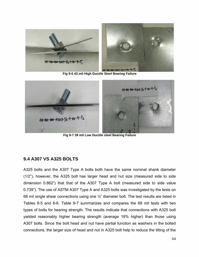
64
Fig 9-6 43 mil High Ductile Steel Bearing Failure
Fig 9-7 39 mil Low Ductile steel Bearing Failure
9.4 A307 VS A325 BOLTS
A325 bolts and the A307 Type A bolts both have the same nominal shank diameter
(1/2”), however, the A325 bolt has larger head and nut size (measured side to side
dimension 0.862”) that that of the A307 Type A bolt (measured side to side value
0.739”). The use of ASTM A307 Type A and A325 bolts was investigated by the tests on
68 mil single shear connections using one ½” diameter bolt. The test results are listed in
Tables 8-5 and 8-6. Table 9-7 summarizes and compares the 68 mil tests with two
types of bolts for bearing strength. The results indicate that connections with A325 bolt
yielded reasonably higher bearing strength (average 18% higher) than those using
A307 bolts. Since the bolt head and nut have partial function as washers in the bolted
connections, the larger size of head and nut in A325 bolt help to reduce the tilting of the
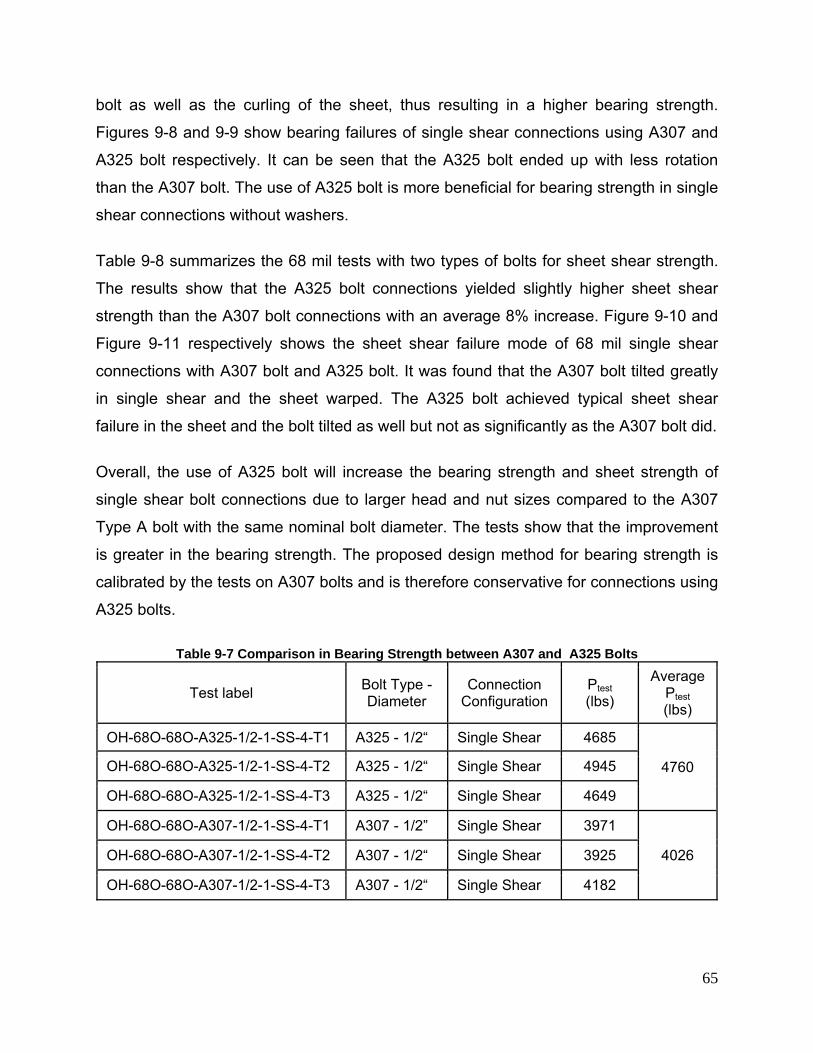
65
bolt as well as the curling of the sheet, thus resulting in a higher bearing strength.
Figures 9-8 and 9-9 show bearing failures of single shear connections using A307 and
A325 bolt respectively. It can be seen that the A325 bolt ended up with less rotation
than the A307 bolt. The use of A325 bolt is more beneficial for bearing strength in single
shear connections without washers.
Table 9-8 summarizes the 68 mil tests with two types of bolts for sheet shear strength.
The results show that the A325 bolt connections yielded slightly higher sheet shear
strength than the A307 bolt connections with an average 8% increase. Figure 9-10 and
Figure 9-11 respectively shows the sheet shear failure mode of 68 mil single shear
connections with A307 bolt and A325 bolt. It was found that the A307 bolt tilted greatly
in single shear and the sheet warped. The A325 bolt achieved typical sheet shear
failure in the sheet and the bolt tilted as well but not as significantly as the A307 bolt did.
Overall, the use of A325 bolt will increase the bearing strength and sheet strength of
single shear bolt connections due to larger head and nut sizes compared to the A307
Type A bolt with the same nominal bolt diameter. The tests show that the improvement
is greater in the bearing strength. The proposed design method for bearing strength is
calibrated by the tests on A307 bolts and is therefore conservative for connections using
A325 bolts.
Table 9-7 Comparison in Bearing Strength between A307 and A325 Bolts
Test label Bolt Type - Diameter
Connection Configuration
Ptest (lbs)
Average Ptest (lbs)
OH-68O-68O-A325-1/2-1-SS-4-T1 A325 - 1/2“ Single Shear 4685
4760 OH-68O-68O-A325-1/2-1-SS-4-T2 A325 - 1/2“ Single Shear 4945
OH-68O-68O-A325-1/2-1-SS-4-T3 A325 - 1/2“ Single Shear 4649
OH-68O-68O-A307-1/2-1-SS-4-T1 A307 - 1/2” Single Shear 3971
4026 OH-68O-68O-A307-1/2-1-SS-4-T2 A307 - 1/2“ Single Shear 3925
OH-68O-68O-A307-1/2-1-SS-4-T3 A307 - 1/2“ Single Shear 4182
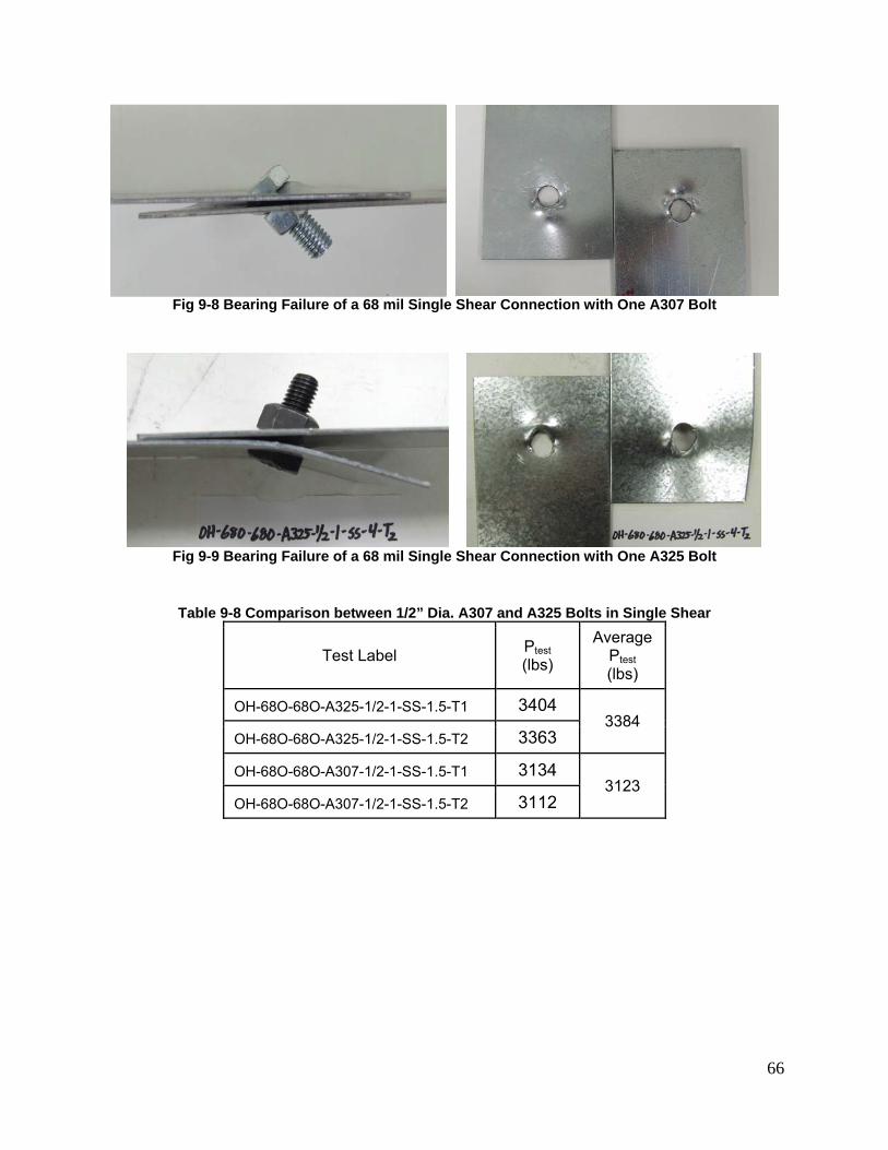
66
Fig 9-8 Bearing Failure of a 68 mil Single Shear Connection with One A307 Bolt
Fig 9-9 Bearing Failure of a 68 mil Single Shear Connection with One A325 Bolt
Table 9-8 Comparison between 1/2” Dia. A307 and A325 Bolts in Single Shear
Test Label Ptest (lbs)
Average Ptest (lbs)
OH-68O-68O-A325-1/2-1-SS-1.5-T1 3404 3384
OH-68O-68O-A325-1/2-1-SS-1.5-T2 3363
OH-68O-68O-A307-1/2-1-SS-1.5-T1 3134 3123
OH-68O-68O-A307-1/2-1-SS-1.5-T2 3112
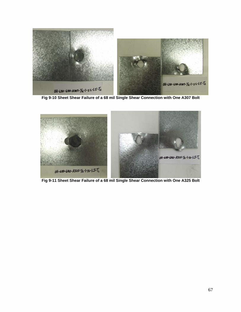
67
Fig 9-10 Sheet Shear Failure of a 68 mil Single Shear Connection with One A307 Bolt
Fig 9-11 Sheet Shear Failure of a 68 mil Single Shear Connection with One A325 Bolt
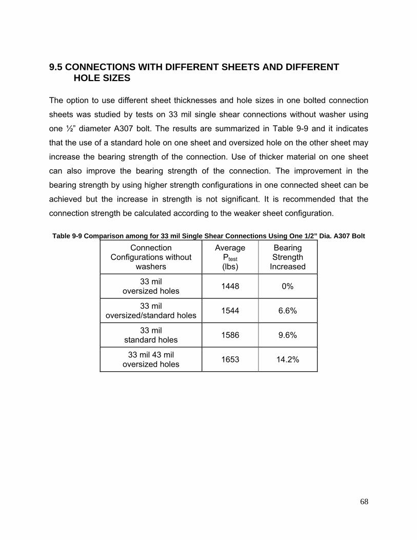
68
9.5 CONNECTIONS WITH DIFFERENT SHEETS AND DIFFERENT HOLE SIZES
The option to use different sheet thicknesses and hole sizes in one bolted connection
sheets was studied by tests on 33 mil single shear connections without washer using
one ½” diameter A307 bolt. The results are summarized in Table 9-9 and it indicates
that the use of a standard hole on one sheet and oversized hole on the other sheet may
increase the bearing strength of the connection. Use of thicker material on one sheet
can also improve the bearing strength of the connection. The improvement in the
bearing strength by using higher strength configurations in one connected sheet can be
achieved but the increase in strength is not significant. It is recommended that the
connection strength be calculated according to the weaker sheet configuration.
Table 9-9 Comparison among for 33 mil Single Shear Connections Using One 1/2” Dia. A307 Bolt
Connection Configurations without
washers
Average Ptest (lbs)
Bearing Strength
Increased
33 mil oversized holes 1448 0%
33 mil oversized/standard holes 1544 6.6%
33 mil standard holes 1586 9.6%
33 mil 43 mil oversized holes 1653 14.2%
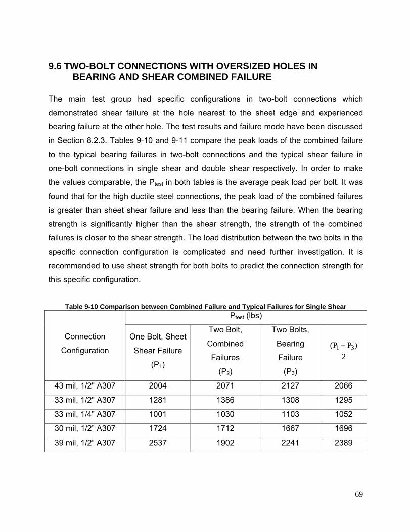
69
9.6 TWO-BOLT CONNECTIONS WITH OVERSIZED HOLES IN BEARING AND SHEAR COMBINED FAILURE
The main test group had specific configurations in two-bolt connections which
demonstrated shear failure at the hole nearest to the sheet edge and experienced
bearing failure at the other hole. The test results and failure mode have been discussed
in Section 8.2.3. Tables 9-10 and 9-11 compare the peak loads of the combined failure
to the typical bearing failures in two-bolt connections and the typical shear failure in
one-bolt connections in single shear and double shear respectively. In order to make
the values comparable, the Ptest in both tables is the average peak load per bolt. It was
found that for the high ductile steel connections, the peak load of the combined failures
is greater than sheet shear failure and less than the bearing failure. When the bearing
strength is significantly higher than the shear strength, the strength of the combined
failures is closer to the shear strength. The load distribution between the two bolts in the
specific connection configuration is complicated and need further investigation. It is
recommended to use sheet strength for both bolts to predict the connection strength for
this specific configuration.
Table 9-10 Comparison between Combined Failure and Typical Failures for Single Shear
Connection
Configuration
Ptest (lbs)
One Bolt, Sheet
Shear Failure
(P1)
Two Bolt,
Combined
Failures
(P2)
Two Bolts,
Bearing
Failure
(P3)
2)PP( 31 +
43 mil, 1/2" A307 2004 2071 2127 2066
33 mil, 1/2" A307 1281 1386 1308 1295
33 mil, 1/4" A307 1001 1030 1103 1052
30 mil, 1/2” A307 1724 1712 1667 1696
39 mil, 1/2” A307 2537 1902 2241 2389
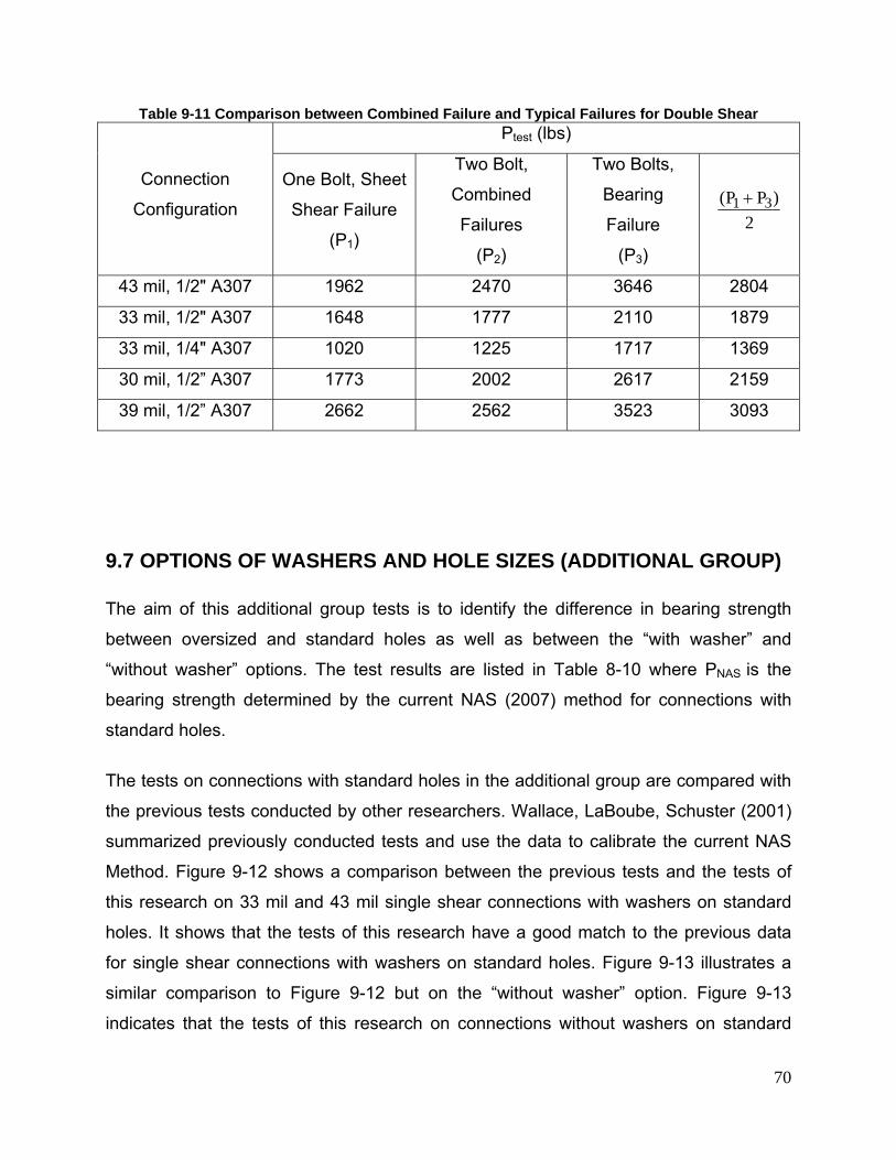
70
Table 9-11 Comparison between Combined Failure and Typical Failures for Double Shear
Connection
Configuration
Ptest (lbs)
One Bolt, Sheet
Shear Failure
(P1)
Two Bolt,
Combined
Failures
(P2)
Two Bolts,
Bearing
Failure
(P3)
2)PP( 31 +
43 mil, 1/2" A307 1962 2470 3646 2804
33 mil, 1/2" A307 1648 1777 2110 1879
33 mil, 1/4" A307 1020 1225 1717 1369
30 mil, 1/2” A307 1773 2002 2617 2159
39 mil, 1/2” A307 2662 2562 3523 3093
9.7 OPTIONS OF WASHERS AND HOLE SIZES (ADDITIONAL GROUP)
The aim of this additional group tests is to identify the difference in bearing strength
between oversized and standard holes as well as between the “with washer” and
“without washer” options. The test results are listed in Table 8-10 where PNAS is the
bearing strength determined by the current NAS (2007) method for connections with
standard holes.
The tests on connections with standard holes in the additional group are compared with
the previous tests conducted by other researchers. Wallace, LaBoube, Schuster (2001)
summarized previously conducted tests and use the data to calibrate the current NAS
Method. Figure 9-12 shows a comparison between the previous tests and the tests of
this research on 33 mil and 43 mil single shear connections with washers on standard
holes. It shows that the tests of this research have a good match to the previous data
for single shear connections with washers on standard holes. Figure 9-13 illustrates a
similar comparison to Figure 9-12 but on the “without washer” option. Figure 9-13
indicates that the tests of this research on connections without washers on standard
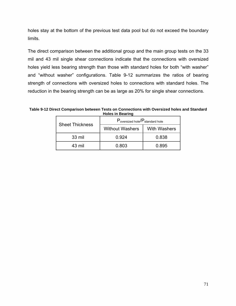
71
holes stay at the bottom of the previous test data pool but do not exceed the boundary
limits.
The direct comparison between the additional group and the main group tests on the 33
mil and 43 mil single shear connections indicate that the connections with oversized
holes yield less bearing strength than those with standard holes for both “with washer”
and “without washer” configurations. Table 9-12 summarizes the ratios of bearing
strength of connections with oversized holes to connections with standard holes. The
reduction in the bearing strength can be as large as 20% for single shear connections.
Table 9-12 Direct Comparison between Tests on Connections with Oversized holes and Standard
Holes in Bearing
Sheet Thickness Poversized hole/Pstandard hole
Without Washers With Washers
33 mil 0.924 0.838
43 mil 0.803 0.895
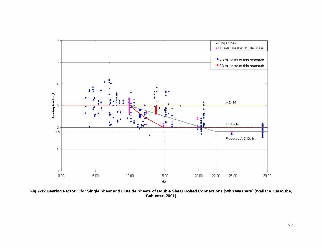
72
43 mil tests of this research33 mil tests of this research
Fig 9-12 Bearing Factor C for Single Shear and Outside Sheets of Double Shear Bolted Connections [With Washers] (Wallace, LaBoube,
Schuster, 2001)
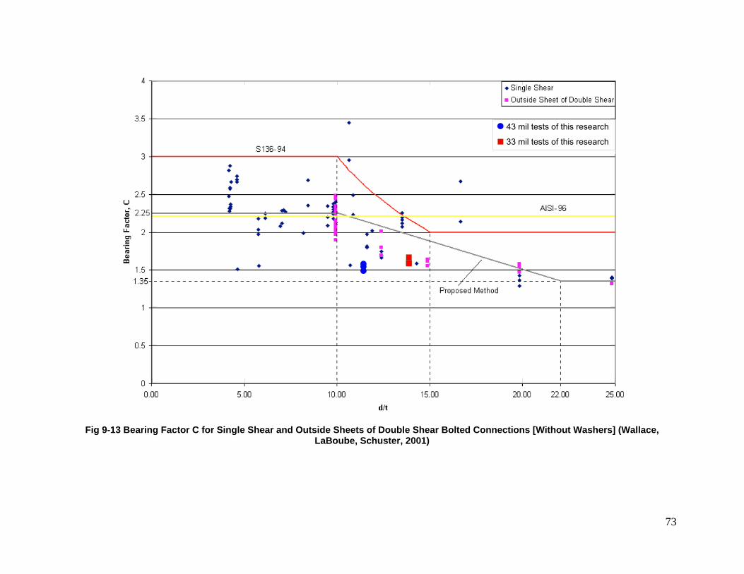
73
43 mil tests of this research
33 mil tests of this research
Fig 9-13 Bearing Factor C for Single Shear and Outside Sheets of Double Shear Bolted Connections [Without Washers] (Wallace,
LaBoube, Schuster, 2001)
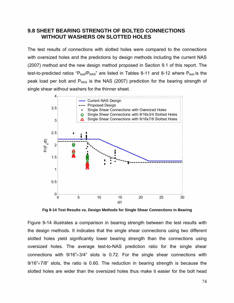
74
9.8 SHEET BEARING STRENGTH OF BOLTED CONNECTIONS WITHOUT WASHERS ON SLOTTED HOLES
The test results of connections with slotted holes were compared to the connections
with oversized holes and the predictions by design methods including the current NAS
(2007) method and the new design method proposed in Section 9.1 of this report. The
test-to-predicted ratios “Ptest/PNAS” are listed in Tables 8-11 and 8-12 where Ptest is the
peak load per bolt and PNAS is the NAS (2007) prediction for the bearing strength of
single shear without washers for the thinner sheet.
0 5 10 15 20 25 300
0.5
1
1.5
2
2.5
3
3.5
4
d/t
P/(F
udt)
Current NAS DesignProposed DesignSingle Shear Connections with Oversized HolesSingle Shear Connections with 9/16x3/4 Slotted HolesSingle Shear Connections with 9/16x7/8 Slotted Holes
Fig 9-14 Test Results vs. Design Methods for Single Shear Connections in Bearing
Figure 9-14 illustrates a comparison in bearing strength between the test results with
the design methods. It indicates that the single shear connections using two different
slotted holes yield significantly lower bearing strength than the connections using
oversized holes. The average test-to-NAS prediction ratio for the single shear
connections with 9/16”×3/4” slots is 0.72. For the single shear connections with
9/16”×7/8” slots, the ratio is 0.60. The reduction in bearing strength is because the
slotted holes are wider than the oversized holes thus make it easier for the bolt head
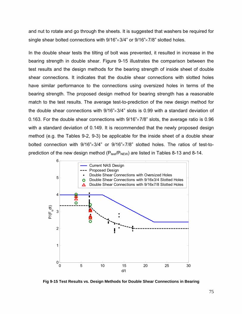
75
and nut to rotate and go through the sheets. It is suggested that washers be required for
single shear bolted connections with 9/16”×3/4” or 9/16”×7/8” slotted holes.
In the double shear tests the tilting of bolt was prevented, it resulted in increase in the
bearing strength in double shear. Figure 9-15 illustrates the comparison between the
test results and the design methods for the bearing strength of inside sheet of double
shear connections. It indicates that the double shear connections with slotted holes
have similar performance to the connections using oversized holes in terms of the
bearing strength. The proposed design method for bearing strength has a reasonable
match to the test results. The average test-to-prediction of the new design method for
the double shear connections with 9/16”×3/4” slots is 0.99 with a standard deviation of
0.163. For the double shear connections with 9/16”×7/8” slots, the average ratio is 0.96
with a standard deviation of 0.149. It is recommended that the newly proposed design
method (e.g. the Tables 9-2, 9-3) be applicable for the inside sheet of a double shear
bolted connection with 9/16”×3/4” or 9/16”×7/8” slotted holes. The ratios of test-to-
prediction of the new design method (Ptest/PNEW) are listed in Tables 8-13 and 8-14.
0 5 10 15 20 25 300
1
2
3
4
5
6
d/t
P/(F
udt)
Current NAS DesignProposed DesignDouble Shear Connections with Oversized HolesDouble Shear Connections with 9/16x3/4 Slotted HolesDouble Shear Connections with 9/16x7/8 Slotted Holes
Fig 9-15 Test Results vs. Design Methods for Double Shear Connections in Bearing
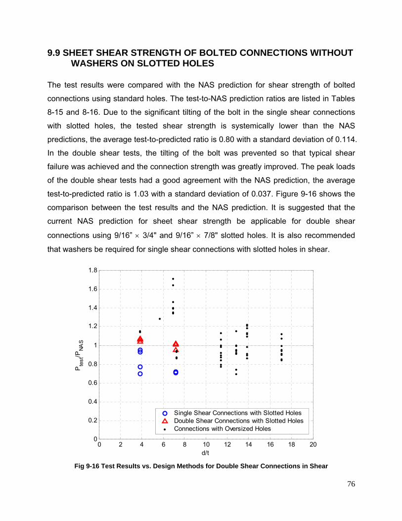
76
9.9 SHEET SHEAR STRENGTH OF BOLTED CONNECTIONS WITHOUT WASHERS ON SLOTTED HOLES
The test results were compared with the NAS prediction for shear strength of bolted
connections using standard holes. The test-to-NAS prediction ratios are listed in Tables
8-15 and 8-16. Due to the significant tilting of the bolt in the single shear connections
with slotted holes, the tested shear strength is systemically lower than the NAS
predictions, the average test-to-predicted ratio is 0.80 with a standard deviation of 0.114.
In the double shear tests, the tilting of the bolt was prevented so that typical shear
failure was achieved and the connection strength was greatly improved. The peak loads
of the double shear tests had a good agreement with the NAS prediction, the average
test-to-predicted ratio is 1.03 with a standard deviation of 0.037. Figure 9-16 shows the
comparison between the test results and the NAS prediction. It is suggested that the
current NAS prediction for sheet shear strength be applicable for double shear
connections using 9/16” × 3/4" and 9/16” × 7/8" slotted holes. It is also recommended
that washers be required for single shear connections with slotted holes in shear.
0 2 4 6 8 10 12 14 16 18 200
0.2
0.4
0.6
0.8
1
1.2
1.4
1.6
1.8
d/t
Pte
st/P
NAS
Single Shear Connections with Slotted HolesDouble Shear Connections with Slotted HolesConnections with Oversized Holes
Fig 9-16 Test Results vs. Design Methods for Double Shear Connections in Shear
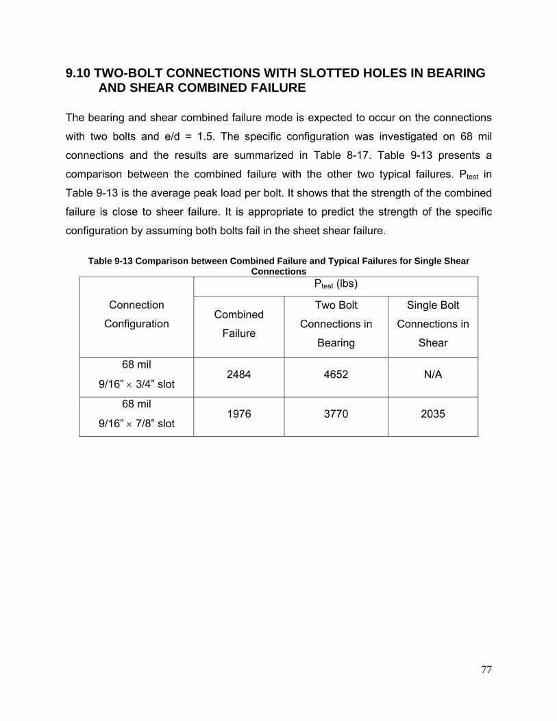
77
9.10 TWO-BOLT CONNECTIONS WITH SLOTTED HOLES IN BEARING AND SHEAR COMBINED FAILURE
The bearing and shear combined failure mode is expected to occur on the connections
with two bolts and e/d = 1.5. The specific configuration was investigated on 68 mil
connections and the results are summarized in Table 8-17. Table 9-13 presents a
comparison between the combined failure with the other two typical failures. Ptest in
Table 9-13 is the average peak load per bolt. It shows that the strength of the combined
failure is close to sheer failure. It is appropriate to predict the strength of the specific
configuration by assuming both bolts fail in the sheet shear failure.
Table 9-13 Comparison between Combined Failure and Typical Failures for Single Shear
Connections
Connection
Configuration
Ptest (lbs)
Combined
Failure
Two Bolt
Connections in
Bearing
Single Bolt
Connections in
Shear
68 mil
9/16” × 3/4” slot 2484 4652 N/A
68 mil
9/16” × 7/8” slot 1976 3770 2035
78
10 PRELIMINARY CONCLUSIONS
The tensile tests on cold-formed steel connections without washers on oversized holes
and slotted holes were conducted to investigate both the sheet shear strength and
bearing strength. The results showed that current NAS (2007) design provisions for the
sheet shear strength worked well for the bolted connections without washers on
oversized holes in both single shear and double shear configurations. The NAS
provisions also had a good agreement with the double shear connections without
washers on slotted holes. The single shear connections without washers on slotted
holes gave relatively low shear strength, therefore it is recommended that washers be
required for single shear connections with slotted holes.
For the bearing strength, the test results showed that the bolted connections without
washer on oversized holes and slotted holes gave lower strength than the connections
with standard holes. Therefore the current NAS design method yielded unconservative
predictions for those connections having greater holes. Based on the test results, new
bearing factor and modification factor were proposed to account for the influence by the
oversized holes. The new design method has a good agreement with to the tested
bearing strength of connections without washers on oversized holes in both single shear
and double shear. The method also works well for connections with slotted holes in
double shear. Large reduction in bearing strength was found on the single shear
connections with slotted holes, it is recommended that washers be required for those
bolted connections.
It was also found that the low ductile steel can be treated equivalently as high ductile
steel in terms of the design method for the bearing and shear strength of connections
without washers on oversized holes. The test results indicated that connections using
ASTM A325 bolts yielded higher bearing strength than connections using ASTM A307
Type A bolts because of the larger head and nut sizes in A325 bolts. This test program
used ASTM A307 Type A bolts for the majority of the specimens, the proposed design
method shall be applicable for connections using ASTM A325 bolts.
79
11 CONTINUING RESEARCH
The Phase 1 research on the bearing failure and shear failure in the sheets was
completed. The research moves forwards to Phase 2 to study the fracture in the net
section of the sheets
12 ACKNOWLEDGEMENT
The funding provided by the American Iron and Steel Institute and the donation of a
portion of the test materials by Simpson Strong-Tie Company, Inc. and BlueScope Steel
Limited is gratefully acknowledged. The assistance and guidance provided by the AISI
COS Oversized Hole Task Group is highly appreciated. The assistance of the UNT
undergraduates George Trabazo, Stephen Mathai, and Szu-Chun Hung in preparing the
test specimens has been invaluable.
80
13 REFERENCES
ASTM A307 (2007). “Standard Specification for Carbon Steel Bolts and Studs, 60 000 PSI Tensile Strength,”. American Society for Testing and Materials, West Conshohocken, PA.
ASTM A325 (2007). “Standard Specification for Structural Bolts, Steel, Heat Treated, 120/105 ksi Minimum Tensile Strength,” American Society for Testing and Materials, West Conshohocken, PA.
ASTM E8 (2001). “E8-01 Standard Test Methods for Tension Testing of Metallic Materials,” American Society for Testing and Materials, West Conshohocken, PA.
Chong, K.P., Matlock, R. B. (1975). “Light-Gage Steel Bolted Connections without Washers,” Journal of the Structural Division, ASCE, vol 101.
Gilchrist, R.T., Chong, K. P. (1979). “Thin Light-Gage Bolted Connection without Washers,” Journal of the Structural Division, ASCE, vol 105.
LaBoube, R. A., Yu, W. W. (1995). “Tensile and Bearing Capacities of Bolted Connections,” Final Summary Report, Civil Engineering Study 95-6, Cold-Formed steel Series, Department of Civil Engineering, University of Missouri-Rolla.
LaBoube, R. A., Yu, W. W. (1996). “Additional Design Considerations for Bolted Connections,” Proceeding of the 13th International Specialty Conference on Cold-Formed Steel Structures, University of Missouri-Rolla.
NAS (2007). “North American Specification for the Design of Cold-Formed Steel Structural Members, 2007 Edition,” American Iron and Steel Institute, Washington, DC
Seleim, S., LaBoube, R. (1995). "Behavior of Low Ductility Steels in Cold-Formed Steel Connections,” Thin-Walled Structures Vol. 25, No. 2, pp. 135 151, 1996
Wallace, J. A,, Schuster, R. M. (2002). “Testing of Bolted Cold-Formed Steel Connections in Bearing (With and Without Washers),” Proceedings of the 16th International Specialty Conference on Cold-Formed Steel Structures, Orlando, FL.
Wallace, J., LaBoube, R., Schuster, R. M. (2001). “Calibrations of Bolted Cold-Formed steel Connections in Bearing (With and Without Washers),” Final Report, American Iron and Steel Institute, Washington, DC.
Yu, W. W. (1982). “AISI Design Criteria for Bolted Connections,” Proceeding of the 6th International Specialty Conference on Cold-Formed Steel Structures, University of Missouri-Rolla.
Zadanfarrokh, F., Bryan, E. R. (1992) “Testing and Design of Bolted Connections in Cold Formed Steel Sections,” Proceedings of Eleventh International Specialty Conference on Cold-Formed Steel Structures, St. Louis, Missouri.
Re
sea
rch
Re
po
rt R
P-0
8-1
1
American Iron and Steel Institute
1140 Connecticut Avenue, NW Suite 705 Washington, DC 20036 www.steel.org