cold war infrastructure for strategic air command: …
TRANSCRIPT
COLD WAR INFRASTRUCTUREFOR STRATEGIC AIR COMMAND:
THE BOMBER MISSION
Prepared for
Headquarters, Air Combat CommandLangley Air Force Base, Virginia
November 1999
i
Table of Contents
Acknowledgments ............................................................................................................................ viiList of Acronyms............................................................................................................................... ixIntroduction....................................................................................................................................... xi
Chapter 1: Cold War Events and the Operational Infrastructure of the Air Force.....................................11946-1950......................................................................................................................................1
The Germans ..............................................................................................................................1The Major Commands and First Generation Infrastructure .............................................................3
ADC and ANG.........................................................................................................................4SAC ........................................................................................................................................5
The 1950s.......................................................................................................................................6Evolution of the Directorate of Civil Engineering ..........................................................................6
Achieving Standardized Design .................................................................................................7Prefabricated Structures, the Steel Industry, and Mobilization......................................................8
The Major Commands and Second Generation Infrastructure .........................................................9ADC and TAC .........................................................................................................................9SAC ...................................................................................................................................... 11
After 1960.................................................................................................................................... 14
Chapter 2: Evolution of Key Property Types ...................................................................................... 19First Generation Maintenance Hangar for the B-36 ......................................................................... 20Second Generation Maintenance Hangar for the B-36, B-47, and B-52 ............................................. 35Prefabricated, Mobilization Infrastructure....................................................................................... 62
Nose Docks, Temporary Shelters, and Wing Hangars .................................................................. 62Prefabricated Airmen Dormitories .............................................................................................. 84
Pavement Experimentation for the Very Heavy Bomber.................................................................. 92Q Areas........................................................................................................................................ 97
A Structures............................................................................................................................ 100C Structure ............................................................................................................................. 104Plants I and II (A and B).......................................................................................................... 104Command and Control Building............................................................................................... 106S Structure.............................................................................................................................. 106
Alert Apron Configurations and Crew Quarters ............................................................................ 107Headquarters Command Post and the SAC Chapel........................................................................ 124
Command Post........................................................................................................................ 124SAC Chapel............................................................................................................................ 126
Late Cold War SAC Infrastructure............................................................................................... 128
Chapter 3: Character-Defining Features and National Register Integrity ............................................. 145First Generation Maintenance Hangar: the Thin-Shell, Concrete Structure...................................... 145Second Generation Maintenance Hangar: the Steel, Double-Cantilever Series................................. 147Prefabricated, Mobilization Infrastructure..................................................................................... 150
Wing Hangars......................................................................................................................... 150SAC Airmen Dormitories......................................................................................................... 152
Experimental Pavement............................................................................................................... 153Q Areas...................................................................................................................................... 154Alert Aprons and Moleholes ........................................................................................................ 155SAC Command Post and Chapel.................................................................................................. 158
Command Post........................................................................................................................ 158Chapel.................................................................................................................................... 158
Late Cold War Infrastructure....................................................................................................... 158

ii
Chapter 4: Real Property Management of Historic SAC Infrastructure ............................................... 159Barksdale Air Force Base ............................................................................................................ 161Beale Air Force Base .................................................................................................................. 162Cannon Air Force Base ............................................................................................................... 163Davis-Monthan Air Force Base ................................................................................................... 164Dyess Air Force Base.................................................................................................................. 165Ellsworth Air Force Base ............................................................................................................ 166Holloman Air Force Base ............................................................................................................ 167Langley Air Force Base .............................................................................................................. 168Minot Air Force Base.................................................................................................................. 169Moody Air Force Base................................................................................................................ 170Mountain Home Air Force Base .................................................................................................. 171Nellis Air Force Base.................................................................................................................. 172Offutt Air Force Base.................................................................................................................. 173Seymour Johnson Air Force Base ................................................................................................ 174Shaw Air Force Base .................................................................................................................. 175Whiteman Air Force Base ........................................................................................................... 176
Chapter 5: Recommendations .......................................................................................................... 177Current ACC Installations: Issues of Inventory ............................................................................. 178
Nose Docks and Wing Hangars................................................................................................ 178Experimental Airfield Pavement............................................................................................... 178Alert Crew Trailers.................................................................................................................. 178
Current ACC Real Property: Issues of Documents and Drawings ................................................... 178Q Areas (1946-1957) ............................................................................................................... 178Thin-Shell Concrete Hangar (1947) .......................................................................................... 178Nose Docks and Wing Hangars (1951-1956) ............................................................................. 179Double-Cantilever Hangar (1951)............................................................................................. 179SAC Airmen Dormitories (1951) .............................................................................................. 179Moleholes (1958-1960) ............................................................................................................ 179
Air Force-Wide: Issues of Inventory and Recordation Across Real Property Types ......................... 179Air Force-Wide: Issues of Documents and Drawings ..................................................................... 180
Bibliography................................................................................................................................... 183General: U.S. Department of Defense and Related........................................................................ 183Baseline Cold War Property Inventories: U.S. Air Force ............................................................... 184Documents: U.S. Air Force ......................................................................................................... 187Drawings: U.S. Air Force and U.S. Army Corps of Engineers........................................................ 191
Document Authorship and Contract Information............................................................................... 195
List of Tables
Table 1. Strategic Air Command Nose Docks and Wing Hangars ................................................... 72Table 2. Strategic Air Command Double-Cantilever Hangar Program October 1957 ...................... 148Table 3. Strategic Air Command Flightline Alert ......................................................................... 156
List of Maps
Map 1. Future Strategic Air Command Bases in 1951................................................................... 12Map 2. CONUS Air Combat Command Installations in 1999...................................................... 160

iii
List of Plates
Plate 1. B-36 hangar at Ellsworth Air Force Base (1953) ............................................................... 19Plate 2. B-36 over Carswell Air Force Base (1953) ....................................................................... 21Plate 3. Presentation drawing of B-36 hangar (1947) ..................................................................... 22Plate 4. Layout plan for B-36 hangars, Loring Air Force Base (1948)............................................. 23Plate 5. Thin-shell concrete hangar constructed outside U.S. (before 1940)..................................... 26Plate 6. U.S. Navy hangars at Patuxent, Maryland (1942) .............................................................. 27Plate 7. Army Air Forces hangars at Wright-Patterson Air Force Base (1999)................................. 27Plate 8. U.S. Army warehouses in Columbus, Ohio (1940) ............................................................ 28Plate 9. B-36 hangar under construction at Ellsworth Air Force Base (1948)................................... 29Plate 10. B-36 hangar under construction at Loring Air Force Base (1948) ....................................... 30Plate 11. B-36 hangar under construction at Ellsworth Air Force Base (1948)................................... 30Plate 12. B-36 hangar at Ellsworth Air Force Base (1999) ............................................................... 31Plate 13. American Airlines hangar at Midway Airport, Chicago (1947)........................................... 32Plate 14. TWA hangar, Midway Airport, Chicago (1948) ................................................................ 32Plate 15. Ink wash drawing for the Denver Coliseum (1951-1952) ................................................... 33Plate 16. View of the Denver Coliseum (1999) ............................................................................... 33Plate 17. Prototype NART hangar at Buckley Field, Denver (1951) ................................................. 34Plate 18. NART hangar at Lincoln, Nebraska (1999)....................................................................... 34Plate 19. Pull-thru hangar, elevation (1956-1958) ........................................................................... 36Plate 20. Pull-thru hangar, plan (1956-1958) .................................................................................. 37Plate 21. New York Port Authority hangars at Idlewild Airport (1949) ............................................. 39Plate 22. Double-cantilever hangar, plan and elevation (1951) ......................................................... 40Plate 23. Double-cantilever hangar at Kirtland Air Force Base (1952) .............................................. 42Plate 24. Double-cantilever hangar at Kirtland Air Force Base (1998) .............................................. 42Plate 25. Kirtland Air Force Base, master plan (1957) ..................................................................... 43Plate 26. Nouasseur Air Base, master plan (1957) ........................................................................... 44Plate 27. Double-cantilever hangar, elevation (1951) ...................................................................... 46Plate 28. Double-cantilever hangar, plan (1951).............................................................................. 47Plate 29. Double-cantilever hangar at the former Loring Air Force Base (1995)................................ 48Plate 30. Double-cantilever hangar at Carswell Air Force Base (mid-1950s)..................................... 49Plate 31. Double-cantilever hangar at Goose Bay Air Base (mid-1950s)........................................... 49Plate 32. Double-cantilever hangar at the former Castle Air Force Base (1998)................................. 50Plate 33. Double-cantilever hangar at the former Walker Air Force Base (1998) ............................... 50Plate 34. Double-cantilever hangar at the former Schilling Air Force Base (1999) ............................ 51Plate 35. Double-cantilever hangar at the former Lincoln Air Force Base (1999) .............................. 51Plate 36. Walker Air Force Base, master plan (1957) ...................................................................... 52Plate 37. Schilling Air Force Base, master plan (1957) .................................................................... 53Plate 38. Lincoln Air Force Base, master Plan (1957)...................................................................... 54Plate 39. Double-cantilever hangar under construction at March Air Force Base (1955) .................... 56Plate 40. Construction for double-cantilever recessing doors .......................................................... 56Plate 41. Hangar doors at the former Mather Air Force Base (1998) ................................................ 57Plate 42. Double-cantilever hangar at Barksdale Air Force Base (1995) ........................................... 57Plate 43. Construction for test hangar at Edwards Air Force Base (1956) ......................................... 59Plate 44. United Airlines hangar, San Francisco International Airport (1959).................................... 60Plate 45. Construction for United Airlines hangar, San Francisco (1958) .......................................... 60Plate 46. Naval Air Station hangar, elevations (1959)...................................................................... 61Plate 47. Navy nose-in dock (1945) ............................................................................................... 63Plate 48. B-29 docks at the flightline, Pinecastle Air Force Base, master plan (1957) ........................ 64Plate 49. Canvas-covered Butler hangar for Army Air Forces (1942) ............................................... 65Plate 50. Erection of superstructure for Butler hangar (1942)........................................................... 65Plate 51. Butler type CH combat hangar, Army Air Forces (1942) ................................................... 66Plate 52. Luria canvas-covered catenary hangar, Army Air Forces (1945) ........................................ 66
iv
Plate 53. Army Air Forces, steel combat hangar, Avon Park, Florida (1995) ..................................... 67Plate 54. Butler prefabricated hangar for the Army Air Forces (1945) .............................................. 67Plate 55. Movable repair docks at Biggs Air Force Base (1951) ....................................................... 68Plate 56. B-36 and movable wing docks at Walker Air Force Base (1952) ........................................ 68Plate 57. B-36 in wing dock at Carswell Air Force Base (1952) ....................................................... 69Plate 58. Mills & Petticord nose dock (1951) .................................................................................. 70Plate 59. B-36 wing hangar at Ellsworth Air Force Base (1999)....................................................... 72Plate 60. Eight B-36 wing hangars at Ellsworth Air Force Base (1957) ............................................ 73Plate 61. Groupings of B-47 wing hangars at McConnell Air Force Base (1952)............................... 74Plate 62. B-47 in flight (1956) ....................................................................................................... 74Plate 63. B-47 aprons at McConnell Air Force Base, master plan (1957) .......................................... 75Plate 64. B-47 wing hangars at Castle Air Force Base, master plan (1957)........................................ 76Plate 65. B-47 wing hangars at Andersen Air Force Base, master plan (1957)................................... 77Plate 66. Luria multi-purpose wing hangar (1951)........................................................................... 78Plate 67. Multi-purpose wing hangars at Ellsworth Air Force Base (1999)........................................ 79Plate 68. Multi-purpose wing hangars at Ellsworth Air Force Base (1999)........................................ 79Plate 69. Multi-purpose wing hangars at Ellsworth Air Force Base (1999)........................................ 80Plate 70. Multi-purpose wing hangar at the former Loring Air Force Base (1995) ............................. 80Plate 71. Multi-purpose wing hangar at the former Lincoln Air Force Base (1999)............................ 81Plate 72. Multi-purpose wing hangar at the former Lincoln Air Force Base (1999)............................ 81Plate 73. Multi-purpose wing hangar at Whiteman Air Force Base (1999) ........................................ 82Plate 74. Multi-purpose wing hangar at the former Forbes Air Force Base (1999) ............................. 82Plate 75. B-52 wing hangar at Offutt Air Force Base (1999) ............................................................ 84Plate 76. Experimental steel dormitory, Camp Grant (1941) ............................................................ 85Plate 77. SAC airmen dormitory at Pease Air Force Base (1957) ..................................................... 85Plate 78. Airmen dormitory at Bergstrom Air Force Base (1952-1953)............................................. 86Plate 79. Renovated SAC airmen dormitories at Ellsworth Air Force Base (1999) ............................ 86Plate 80. SAC airmen dormitories at Pease Air Force Base, master plan (1957) ................................ 87Plate 81. Advertisement for Fenestra System (Offutt dorms) (1952) ................................................. 88Plate 82. Advertisement for Fenestra System (1952) ....................................................................... 89Plate 83. SAC airmen dormitory (drawing), Ellsworth Air Force Base (1952)................................... 90Plate 84. Fenestra portable classroom for South Carolina (1955) ...................................................... 92Plate 85. Asphaltic concrete paving at Loring Air Force Base (1948) ............................................... 95Plate 86. Concrete overruns and warm-up pads at Loring Air Force Base (1956) .............................. 95Plate 87. Paver laying tar-rubber surface at Homestead Air Force Base (1955) ................................. 96Plate 88. Technical specifications for surface at Homestead Air Force Base (1955)........................... 96Plate 89. Q Area personnel passes at Travis Air Force Base (1959) .................................................. 97Plate 90. Aerial view of the Q Area at Travis Air Force Base (1962 or 1963).................................... 99Plate 91. The A Structure in the Q Area at Barksdale Air Force Base (1995) .................................. 100Plate 92. The A Structure in the Q Area at the former Loring Air Force Base (1995)....................... 101Plate 93. The A Structure in the Q Area at Travis Air Force Base (1995)........................................ 101Plate 94. A-1 Structure in the Q Area at the former Loring Air Force Base (1995) .......................... 102Plate 95. A-1 Structure in the Q Area at the former Loring Air Force Base (1995) .......................... 102Plate 96. The A Building of the Martin Bomber Plant (1999)......................................................... 103Plate 97. The A Building, first SAC Command Headquarters (1999) ............................................. 103Plate 98. Plant I (A) in the Q Area at Ellsworth Air Force Base (1995)........................................... 104Plate 99 Plant II (B) in the Q Area at Ellsworth Air Force Base (1995).......................................... 105Plate 100. Command/Control Bldg., Q Area, former Loring Air Force Base (1957) .......................... 105Plate 101. SAC aprons and taxiway at Griffiss Air Force Base, master plan (1957) ........................... 110Plate 102. SAC hot cargo loading apron at Travis Air Force Base, master plan (1957) ...................... 111Plate 103. SAC alert aprons at Mountain Home Air Force Base, master plan (1957) ......................... 112Plate 104. SAC stubbed alert apron at Bergstrom Air Force Base, master plan (1957) ....................... 113Plate 105. Christmas tree alert apron at Wurtsmith Air Force Base, master plan (1957) ..................... 114Plate 106. Aerial view of SAC alert at McChord Air Force Base (1969)........................................... 115
v
Plate 107. Aerial view of SAC alert at Whiteman Air Force Base (1959) ......................................... 116Plate 108. SAC practice alert in progress (1960) ............................................................................. 117Plate 109. KC-135 refueling B-52 in mid-flight (1956) ................................................................... 118Plate 110. SAC molehole at Whiteman Air Force Base (1999) ........................................................ 118Plate 111. SAC molehole at the former Schilling Air Force Base (1999) .......................................... 119Plate 112. SAC molehole at the former Castle Air Force Base (1998) .............................................. 119Plate 113. Tunnel egress, molehole at the former Castle Air Force Base (1998) ................................ 120Plate 114. SAC molehole at the former Homestead Air Force Base (1995) ....................................... 121Plate 115. SAC molehole at the former Homestead Air Force Base (1995) ....................................... 121Plate 116. SAC tanker alert trailers at Griffiss Air Force Base (1964) .............................................. 123Plate 117. SAC Command Headquarters at Offutt Air Force Base (1957)......................................... 125Plate 118. SAC Command Headquarters, underground structure (1957) ........................................... 125Plate 119. Detail of Reflex Actions mapped on the “big board” (1957)............................................. 126Plate 120. SAC chapel at Offutt Air Force Base (1999) ................................................................... 127Plate 121. Stained glass window depicting SAC’s Sixteenth Air Force (1958-1960) ......................... 128Plate 122. NEACP hangar at Offutt Air Force Base (1999) ............................................................. 129Plate 123. PACCS/NEACP maintenance hangar at Offutt Air Force Base (1999) ............................. 131Plate 124. B-1 maintenance hangar at Dyess Air Force Base (1995)................................................. 131Plate 125. Wing hangars remodeled for the B-1 at Ellsworth Air Force Base (1999) ......................... 132Plate 126. B-2 shelters at Whiteman Air Force Base (1999) ............................................................ 132Plate 127. New construction near the B-36 hangar at Ellsworth Air Force Base (1999) ..................... 146Plate 128. Double-cantilever hangar at Shaw Air Force Base (mid-1950s)........................................ 149Plate 129. Renovated double-cantilever hangar at Whiteman Air Force Base (1999) ......................... 149Plate 130. Additions to B-52 wing hangar at Ellsworth Air Force Base (1999) ................................. 151Plate 131. B-52 and multi-purpose wing hangars at Ellsworth Air Force Base (1999) ....................... 151Plate 132. Remodeled SAC dormitory at Ellsworth Air Force Base (1999) ....................................... 153Plate 133. Heavily renovated molehole at Grand Forks Air Force Base (1995) ................................. 157

vi
vii
Acknowledgments
Many individuals contributed to the research and analysis presented here. Again, the author wishes tothank Dr. Paul Green at Air Combat Command Headquarters and the dedicated staff of the Air ForceHistorical Research Agency, at Langley and Maxwell Air Force Bases, respectively. Studies such as theone following would not be possible without the encouragement of the Air Force at the major commandlevel, while the archives at the Air Force Historical Research Agency, and the additional collections of theAir University, continue to support scholarly excellence in the pursuit of military history. At the AirForce Historical Research Agency, in particular, the author wishes to heartily thank archivists JosephCaver and Essie Roberts, as well as declassification specialist Archie DiFante. After six years of researchat the Air Force Historical Research Agency, the author still finds its collections unmatched for solvingriddles of Air Force architectural-engineering history and for clarifying links between infrastructure andmissions of the Cold War. The author also wishes to acknowledge two threshold studies of Air Forcehistory that continue to inspire: Kenneth Schaffel’s The Emerging Shield: The Air Force and theEvaluation of Continental Air Defense 1945-1960 and Jacob Neufeld’s The Development of BallisticMissiles in the United States Air Force (1945-1960), publications of 1991 and 1990 from the Office ofAir Force History. These two histories, like the two companion volumes presented here, look closely atAir Defense Command and Strategic Air Command during the first period of the Cold War, weavingtogether a complex tapestry of events and missions. Both touch on issues of infrastructure, and suggestedmuch of the research explored here.
The author also wishes to express gratitude to all of those historians, engineers, archivists, real propertymanagers, pilots, aircraft maintenance crews, buildings specialists, and preservation planners who year byyear have contributed to these two studies. Research for Cold War Infrastructure for Strategic AirCommand: the Bomber Mission and Cold War Infrastructure for Air Defense: the Fighter and CommandMissions is intertwined, and is directly built upon work done on these same topics, 1995-1998. Manypeople have offered their special knowledge. The author wishes to thank the cultural resource managersof Andrews, Beale, Cannon, Charleston, Dover, Eglin, Ellsworth, Grand Forks, Holloman, Kirtland,McChord, Minot, Offutt, Scott, Travis, Vandenberg, Whiteman, and Wright-Patterson Air Force Bases, aswell as personnel from the civil engineering vaults at these installations and from Barksdale and Langleyin addition. The Air National Guard at Andrews, Kirtland, Lincoln (Nebraska), and New Castle(Delaware) also contributed information to the research, sharing maintenance manuals and discussinghistoric photographs and drawings. The author continues to learn from conversations with Robert V.Nelson, a hangar door maintenance and repair specialist, and from William Hisle, a retired Air Forceaircraft maintenance crew member for the B-36 and the B-52 during the 1950s. Invaluable informationwas also forthcoming from Kansas City engineers Norm Rimmer of Butler Manufacturing and HarryCallahan of Black & Veatch, and Philadelphia engineer Arthur Kuljian of Kuljian Corporation. KevinNelson and Norman E. Onnen were additionally very helpful in making arrangements at Black & Veatch.Princeton University civil engineering professor David Billington kindly opened the Anton Tedeskoarchives to the author, and provided the superlative images of Tedesko’s work reproduced here. Drs.Martin K. Gordon and Martin A. Reuss, historians at the History Office, U.S. Army Corps of Engineers,Humphreys Engineering Center, Fort Belvoir, supported the author in addressing the issue of standardizeddrawings and in finding the Tedesko archives at Princeton. Historian Julie Webster at the U.S. ArmyCorps of Engineers, Construction Engineering Research Laboratories, Champaign-Urbana, discussed herdraft work on aircraft hangars, and through her research makes a contribution here. Finally, the authorthanks the staff at the National Archives II.
All such studies also depend on the team efforts needed to produce the polished final volumes. The authorthanks her co-workers at KEA Environmental, and is especially grateful to staff members Julie Mentzer,Gina Zanelli, and Jack Meischen for their efforts in word processing and graphics. Illustrations presentedin these volumes were particularly complex, and would not have been possible without the contributionsof Ron Myers of the Air Force Historical Research Agency; the U.S. Army Corps of Engineers HistoryOffice (with Maurie Warner of Leet-Melbrook); Princeton University; Christine Tuttle, SSgt. Gary E.

viii
Johnston, Gene Svensen, Art Kincaid, and Frank J. Tokarsky of Ellsworth, Kirtland, McConnell, Offutt,Whiteman and Wright-Patterson Air Force Bases; the Nebraska State Historical Society (with specialthanks to Bill Callahan); Clyde E. Wills and Kathleen V. Missman of Butler Manufacturing; Geo-Marine,Inc.; and Mariah Associates, Inc.
ix
List of Acronyms
AAF Army Air ForcesABM Antiballistic MissileACC Air Combat CommandAC & W Aircraft Control and WarningADC Air Defense CommandAEC Atomic Energy CommissionAETC Air Education and Training CommandAFIRO Air Force Installation Representative OfficeAFRC Air Force Reserve CommandAFSWP Armed Forces Special Weapons ProjectALCM Air-Launched Cruise MissileAMC Air Materiel CommandAMC Air Mobility CommandANG Air National GuardARDC Air Research and Development CommandBESM bystrodeistvuiushchaia elektronnaia schetnaia mashinaBMEWS Ballistic Missile Early Warning SystemBUIC Backup Interceptor ControlCBR California Bearing RatioCIOS Combined Intelligence Objectives SubcommitteeCOC Command Operations CenterCONUS Continental United StatesDASA Defense Atomic Support AgencyDNA Defense Nuclear AgencyDEW Distant Early Warning SystemDoD Department of DefenseFAA Federal Aviation AgencyFIAT Field Information Agency, TechnicalHABS Historic American Building SurveyHAER Historic American Engineering RecordHB Heavy BomberIBM International Business MachinesICBM Intercontinental Ballistic MissileIRBM Intermediate Range Ballistic MissileJAL Japan AirlinesJSS Joint Surveillance SystemMB Medium BomberMIRV Multiple Independently Targetable Re-Entry VehiclesMk 17 Mark 17MLC Military Liaison CommitteeNACA National Advisory Committee for AeronauticsNART Navy Air Reserve TrainingNASA National Aeronautics and Space AdministrationNEACP National Emergency Airborne Command PostNGB National Guard BureauNORAD North American Air DefenseNSC National Security CouncilNWS North Warning System
x
OTH-B Over-the-Horizon BackscatterOTS Office of Technical ServicesPACCS Post-Attack Command and Control SystemPAVE PAWS Perimeter Acquisition Vehicle Entry Phased-Array
Warning SystemSAC Strategic Air CommandSAGE Semi-Automatic Ground EnvironmentSALT Strategic Arms Limitations TreatySCC Super Combat CenterSDI Strategic Defense InitiativeSLBM Submarine-Launched Ballistic MissileSRAM Short-Range Attack MissileSTART Strategic Arms Reduction TreatyTAC Tactical Air CommandTN ThermonuclearTWA Trans World AirlinesUSACERL United States Army Corps of Engineers
Construction Engineering Research LaboratoriesUSAF United States Air ForceUSAFE United States Air Force in EuropeVVHB Very Very Heavy BomberWACS White Alice Communications SystemWAI Weidlinger Associates, Inc.X-1 Expansible, BasicX-2 Expansible, IntermediateX-3 Expansible, UltimateZD Zeiss-Dywidag

xi
Introduction
During fiscal year 1998-1999 Air Combat Command (ACC), Headquarters, Langley Air Force Base,sponsored two historic contexts focused on the Cold War bomber, fighter, and command/control missionswithin Strategic Air Command (SAC), Air Defense Command (ADC), and Tactical Air Command(TAC). The contexts address the history of flightline real property supporting these missions from 1947 to1991, with an emphasis on buildings and structures of the 1947 to 1963 period. Organized as twocompanion volumes, Cold War Infrastructure for Strategic Air Command: the Bomber Mission and ColdWar Infrastructure for Air Defense: the Fighter and Command Missions, the contexts substantiallycomplete the inventory and preliminary assessment of Cold War infrastructure undertaken during 1995-1997 across ACC installations. Each context strives to achieve two basic goals and is intended to opendiscussions between real property managers across the Department of Defense (DoD).
The primary goal of the contexts is to establish a detailed history for categories of SAC, ADC, and TACCold War infrastructure. A growing number of individuals who interpret cultural resources within the AirForce, the National Park Service, and State Offices of Historic Preservation have come to believe thathistoric properties of the recent past are critically important to our nation’s heritage. Air Force propertiesin particular offer a physical landscape through which historians can interpret not just the Cold War, butalso modern achievements in structural engineering. Completed studies suggest that certain types of AirForce property, in documented cases, are potentially eligible for the National Register of Historic Places.The contexts seek to support the appropriate general assessments to date, to clarify areas of uncertainty,and to open doors to further research.
Over the past decade the Air Force has reviewed a number of studies assessing Cold War buildings andstructures, beginning with work at Vandenberg Air Force Base in Southern California. Under the DoDLegacy Resource Management Program during fiscal years 1993 through 1996, complex and variedprojects pulled together information and established benchmark histories for selected Cold War themeswithin the Air Force. While the resulting repository of reports still requires centralized andcomprehensive assessment, much has been done. The Air Force Center for Environmental Excellence atBrooks Air Force Base, San Antonio, is compiling a bibliography of these studies and has partnered withthe U.S. Army Corps of Engineers Construction Engineering Research Laboratories in Champaign-Urbana, Illinois, to distribute a newsletter tracking Cold War history projects. Yet, a critical difficulty hasremained. Many of the reports are hard to access and predictably most new studies are unable to benefitfrom the work that precedes them. Often research is focused locally, with a case for National Registersignificance broadly made. In many instances, the significance argument is weak, tied only to generalpolitical history and big moments in the Cold War. Achievement of the historic infrastructure was indeeda federal program—usually with buildout across the nation in multiples ranging from about 20 to 60, butwas a program with a particularly detailed engineering history. The paired Cold War Infrastructurevolumes here presented offer readers that history, and supplement the existing regional assessments.
The secondary goal of the contexts is to initiate a dialogue tying the history of relevant Air Force propertytypes to parameters of the National Register of Historic Places—such as character-defining features andintegrity. Examples of such property types include the double-cantilever hangar required for maintenanceof SAC bombers and the alert hangar manned by ADC and TAC for air defense. Buildings and structuressuch as these are defined by physical components that illustrate their historic significance, and many ofthese components are reflective of architectural and engineering details. Issues of National Registerintegrity for Air Force property relate to the amount of change over time. Not surprisingly, integrity is notas straightforward as it might seem. Integrity is also linked to architectural and engineering detail, and tothe types of changes that affect the original character-defining features of the potential historic resource.Some changes do not materially damage integrity; others destroy it. At times, changes can even enhanceintegrity and strengthen historic significance, when changes occur early in the history of a structure andare really a fine-tuning of original planning and programmatic design.

xii
Finally, the contexts briefly summarize the results of the multi-volume study, A Systemic Study of AirCombat Command Cold War Material Culture, completed by ACC in 1997. Cold War Infrastructure forStrategic Air Command: the Bomber Mission includes single-page abstracts, by installation, of theexisting SAC bomber infrastructure discussed within its illustrated context of eight key property types.Cold War Infrastructure for Air Defense: the Fighter and Command Missions includes single-pageabstracts, again by installation, of the existing ADC / TAC fighter and command/control infrastructurediscussed within its illustrated context of seven key property types. Recommendations conclude bothvolumes, addressing remaining context and inventory issues across today’s ACC installations, as well asconsidering broader parallel issues across the Air Force and DoD.
1
Chapter 1: Cold War Events and the Operational Infrastructure of the Air Force
During the more than half-century that unfolded between the closing months of World War II andwinding down of the Cold War in 1989-1991, the U.S. War Department evolved into the Department ofDefense as it is now understood, with its primary supporting arms of the Army, Navy, Marines, and AirForce, and its reserve forces of the Army, Air Force, and Air National Guards. American militaryinfrastructure is predominantly a phenomenon of the 1939-to-present period, thus precisely paralleling themodern movement in Western European and U.S. architecture and engineering. The years bracketed by1945 and 1991 also mirror a particular world condition with regards to the development of nuclearweapons. During these decades knowledge within the scientific community emerged exponentially, yetwas closely held by the two competing super powers of the U.S. and the Soviet Union into the 1980s.Coupled with strides in physics and mathematics accompanying the shifts from atomic to thermonuclearweaponry, were significant gains in computer capabilities, electronics, and the conquest of near- and far-space—all of which directly supported military activities such as higher order aircraft, radar surveillance,command and control, satellite monitoring, long-range missiles, smart weapons systems, unmanneddevices, and general intelligence.
1946-1950
The Army Air Forces (AAF), within the U.S. Army, had become an almost autonomous military arm bythe close of World War II. The AAF represented the powerful changes that were coming about as airwarfare dominated the strategies and defenses of nations at mid-century. As Air University professorEugene M. Emme underscored in The Impact of Air Power, written for the Office of Civil and DefenseMobilization at the end of the 1950s, “the exploitation of air space [will] be of central importance inhelping determine the ultimate fate of civilization,” further noting that “[a]ir power must bedispassionately assessed by American professionals and students of military, diplomatic, and scientificaffairs alike.”1 To accomplish these comprehensive goals, the War Department channeled significantenergies into air power, even during times of federal funding cutbacks. Within the air arm of the U.S.military during 1945 through 1947 were more than the emerging technological advances of jets, aerialrefueling, and jet-fighter and jet-bomber carried weapons. Also within the AAF, and soon to be AirForce, were the scientists and engineers focused on mastering space through specific surveillance,communications, and weapons systems, and through aeromedical programs determined to place man atever-higher altitudes under stressed gravitational forces at Mach speeds.
The Germans
The outcome of World War II in Europe, stridently reinforced through the immediate onset of the ColdWar, directly assisted both American and Soviet military efforts in the arena of near- and far-space. Bothnations heavily removed, captured, and recruited German scientists and engineers between 1945 and1955. 2 Through Project Overcast, and sequentially Project Paperclip and Project 63, the U.S. governmentbrought over 650 German specialists into the country with their families. During the early post-war years,the Combined Intelligence Objectives Subcommittee (CIOS) kept a card file of the assumed locations ofan additional 5,000 German scientists. While the 1945 to 1947 years rightly can be interpreted as chaos-driven, they were also systematic: the Office of Technical Services (OTS) in Washington, D.C., workedthrough the Field Information Agency, Technical (FIAT) in Germany to sponsor recruiters representingAmerican businesses on over 3,000 field trips. These recruiters gathered industrial information of allkinds, including samples of experimental technology and equipment. The U.S. government microfilmedGerman scientific records, disseminating these to contractors supporting the military. Other largeAmerican intelligence operations involving the German scientific community included Apple Pie, usingformer German military personnel to assess the state of the Soviet industrial economy; Panhandle, payingformer German military intelligence to continue its information gathering on the Soviet Union and thecountries within its sphere of influence; Credulity, a continuous tracking of German scientists stilldesired, but not yet recruited; Echo, a plan to find German scientists dispersed to Eastern Europe; and

2
Esso, a study to move another 1,500 German scientists and engineers to the U.S. American Men ofScience listed approximately one-fourth of the German emigrant group of 1945-1952: half of these menhad Ph.D.s upon their arrival in the U.S.
While the best known of the German scientific community was Wernher von Braun’s group of rocketspecialists from Peenemünde—many of whom ended up working for the Army on its missile program atHunstville—this group was relatively small, under 100 at its height in the late 1950s. Dispersedthroughout the Air Force, particularly through the Air Research and Development Command (ARDC),the National Advisory Committee for Aeronautics (NACA) and the National Aeronautics and SpaceAdministration (NASA), and sister test installations within the Navy, were over 500 key men. Of note, apercentage of these individuals began leaving the civil service of the Army and Air Force for jobs withAmerican military contracting companies like Bell, Martin, North American Aviation, Convair, Avco,and Raytheon by the late 1950s. The ripple effects of the German scientific-engineering community ofWorld War II are many and subtle. Those who stayed within the U.S. military civil service system oftenworked at the GS-15 to GS-17 level—the uppermost grade levels within the system. Those who left werebehind the scenes in noteworthy places. Convair manufactured the B-36. Bell, Martin, and NorthAmerican Aviation designed and manufactured important early guided missiles, some planned and testedwith special warheads. Avco designed the Atlas intercontinental ballistic missile (ICBM) warhead.Raytheon led the research, testing, and development for the large phased-array radars crucial to theAmerican antiballistic missile (ABM) system and long-range radar surveillance.
Examples include Dr. Ernst A . Steinhoff, Dr. Martin Schilling, and Dr. Bruno Balke, among many.Steinhoff worked for ARDC over the life of his American career. He was both in and out of a directliaison with the Air Force—running a recruitment effort for Project 63 in the early 1950s, building up theAir Development Center at Holloman Air Force Base through most of the decade; hiring with contractorstied to initial developments at Vandenberg Air Force Base, California; working within the RAND thinktank in Santa Monica; taking a visiting professorship at the Massachusetts Institute of Technology inaerophysics; serving as a special assistant and scientific advisor to several key Air Force laboratories; andperiodically speaking before the Scientific Advisory Board in Washington, D.C. At Huntsville with vonBraun, Dr. Schilling became chief of the project management staff for the Army Guided MissileAgency’s research and development division. Raytheon hired Dr. Schilling in 1958. Through 1976, heled the development of the large phased-array radar—retiring in the early stages of the PerimeterAcquisition Vehicle Entry Phased-Array Warning System (PAVE PAWS) project. The American systemof large phased-array radars is only currently being completed, with the last radar in the group scheduledfor operational status at Clear Air Force Station, Alaska, in 2000. 3 Dr. Balke was a military high-altitudeconditioning and human endurance specialist, recruited from Germany in 1950. He worked at the AirForce School of Aviation Medicine in San Antonio, and eventually became chief of the bio-dynamicsbranch at the Civil Aeromedical Research Institute of the Federal Aviation Administration. 4
The German brain drain into the American Air Force scientific-engineering community, and into theranks of the Air Force’s civil service and its contractors, is of more than passing consequence. Thebuildings and structures that made up the overall infrastructure of the Air Force Cold War builtenvironment, excluding those of the supportive cantonments, were a direct outgrowth of the sequentiallypioneered aircraft, weapons, and communications / surveillance systems. Design of the physical housingfor the large phased-array radar is a case in point: the structure’s form almost purely met the system’sengineering parameters, and is architectonic rather than architectural. As such, what we see is really thedesign of Dr. Martin. Of additional interest, the German scientist-engineering group had a counterpart inarchitecture and engineering during these same decades. German architects and engineers, and German-educated professionals in neighboring Germanic countries (particularly Austria and Czechoslovakia), hadsteady contact with their American counterparts from about 1910.
During the teens and twenties, architects Antonin Raymond, Rudolph Schindler, and Richard Neutra, andengineers John Kalinka and Anton Tedesko, immigrated to the U.S. Raymond, Schindler and Neutra all

3
hired with Frank Lloyd Wright in Chicago very early in their American careers. Kalinka and Tedeskohired with Roberts & Schaefer, another Chicago firm, while maintaining active connections with theGerman firm Dykerhoff & Widmann. With the rise of Hitler during the 1930s, the situation quicklybecame much more complex. A number of internationally prominent architects left Germany for GreatBritain, Turkey and South America, and, by late in the decade or early in the 1940s, for the U.S. Thosechoosing America included Mies van der Rohe, Ludwig Hilberseimer, Walter Peterhans, EricMendelsohn, Konrad Wachsmann, Paul Weidlinger, and Walter Gropius, clustering in the Boston-(Harvard)-to-New York – New Jersey (Princeton) corridor and in Chicago (Illinois Institute ofTechnology). Raymond, Mendelsohn, and Wachsmann worked directly for the War Department in theearly 1940s, designing test structures for the Chemical Warfare Service, with assistance fromHilberseimer and from Detroit architect Albert Kahn. Weidlinger and Wachsmann patented an innovativedouble-cantilever hangar in 1945, and in 1949 Weidlinger formed Weidlinger Associates, a collaborate ofengineers based in New York that undertook multiple assignments for the American military specializingin long-span structures, as well as blast-proof and hardened construction. Weidlinger Associates handlednumerous airfield assignments, civil and military, including full services for Lajes Air Force Base in theAzores in 1955. The blast-proof specialty encompassed U.S. embassies worldwide; above- andunderground command and control, and intelligence, facilities; and research and development militarytesting centers.5 Wachsmann would surface again during the early Cold War for hangar design, as aspecial consultant to the Air Force, not unlike Dr. Steinhoff.6
Engineer Anton Tedesko, like Wachsmann, also made key contributions to the design and development ofAir Force structures. When Dr. Tedesko came to the U.S. in the middle 1920s, he brought with him aspecial contractual agreement for the American distribution of the Zeiss-Dywidag [Dykerhoff & WidmannA.G.]—or ZD—thin-shell concrete construction system. An early prominent Tedesko example of ZDconstruction was a building for the World’s Fair in Chicago during 1934. By the late 1930s, Tedesko,through the Chicago firm Roberts & Schaefer, was designing hangars, shops, and depot facilities for theU.S. Navy and Army. Tedesko’s large-span thin-shell concrete hangar of 1947 for Strategic AirCommand (SAC) was among the very first significant Cold War infrastructure designed for the Air Force,and was the largest hangar in the world when erected. Tedesko also later became a special consultant toAir Force headquarters, 1955-1970, as a “troubleshooter [for] decisions leading to innovative solutionsfor new construction and renovation.” Dr. Tedesko, with a Roberts & Schaefer team, designedunderground launch control domes for the Air Force ballistic missiles, and for the launch pad and controldome of the Atlas Centaur space vehicle for NASA at Cape Canaveral. In the middle 1960s—nearly 20years after his hangar for SAC—he designed and engineered the assembly and launch facilities for theApollo manned lunar landing program. The architectural-engineering work of Konrad Wachsmann andAnton Tedesko, in particular, was strongly tied to the scientific-engineering research and advancementsof the Wernher von Braun Peenemünde group.7
The Major Commands and First Generation Infrastructure
The Air Force itself was a Cold War phenomenon, created in tandem with the Department of Defense(DoD) (replacing the War Department) and the National Security Council in July 1947 through theNational Defense Act. Even the term, Cold War, originated during 1947 as a reaction by journalistWalter Lippmann to “The Sources of Soviet Conduct,” an article written by George F. Kennan forForeign Affairs and published the exact month, July, of the birth of the Air Force.8 The National SecurityCouncil (NSC) was the issuer of key Cold War policy statements throughout the 1950s, while the AirForce took on its Cold War mantel across its lead commands. For the latter, the Air Force sustained itsstructure as set up in March 1946 by the AAF, with three primary commands: SAC, Air DefenseCommand (ADC), and Tactical Air Command (TAC). In October 1947, formal Air Force structureexpanded to include Air Materiel Command (AMC), as well as commands directing the Air University,the Air Proving Ground, training, and geographical jurisdictions worldwide. After 1947 the Air Forceadded the ARDC.9 Directly supportive of the AAF, and then the Air Force, was the Air National Guard(ANG). General Carl Spaatz, Chief of Staff of the War Department, who had established SAC, TAC, and

4
ADC in 1946, had prioritized funding for SAC and TAC. The early Cold War air defense mission fellalmost entirely to ANG, and then ADC. Each of the operational Air Force commands had special,pressing needs. AMC and ARDC focused on storage of materiel, and, research, development, testing, andevaluation missions associated with weapons systems and equipment.
On 1 August 1946, President Truman signed into law the Atomic Energy Act, which established civiliancontrol over the research, development and management of what would become nuclear energy. TheCongressional controversy of civilian versus military responsibility and oversight was enormous, withConnecticut Senator Brian McMahon and Michigan Senator Arthur H. Vandenberg taking the respectiveopposite positions. Vandenberg’s amendment to the McMahon Bill essentially gave the military vetopower over the administrative agency, the Atomic Energy Commission (AEC). A Military LiaisonCommittee (MLC) channeled the interface between the AEC and DoD at the policy level, while a keynew entity, the Armed Forces Special Weapons Project (AFSWP), handled the operational level.Secretary of War Robert Patterson and Secretary of the Navy James V. Forrestal established the AFSWP,effective 31 December 1946. The AFSWP became responsible for the armed forces’ development ofnuclear energy. The AFSWP took over the management of the Sandia Laboratories in New Mexico,expanding the labs for nuclear weapons production, testing, and engineering of storage facilities. From1946 into the middle 1950s, the AFSWP built and operated national and operational atomic, and as of1954, thermonuclear, bomb storage sites in the U.S. and internationally. Known as Q Areas, theseweapons depots were special, and supported the strategic bombing mission of General Curtis LeMay’sSAC beginning in October 1948. 10
ADC and ANG
Each command within the new Air Force required infrastructure to sustain its mission.11 Priorities layfirst with SAC, yet initial activities concentrated within ADC and ANG. Military planners assumed thatsole possession of the atomic bomb, coupled with a lead in the race for long-range aircraft, allowed for adelay in permanent provisions for air defense. Regardless, radar and fighter-interceptor capabilities weremanifest. ANG and ADC cobbled together the defensive mission, 1946-1948, reusing World War IIradars and operating command and control, as well as ground observation stations, in makeshift quarters.Available American pursuit aircraft were all propeller-type. AAF airfields had runways only long enoughto support the F-47 and the F-51, but lacked the minimum length of 7,000 feet required for jet operation.While the paperwork went forward to activate and expand mothballed installations, the AAF authorizedthe design and construction of a Cold War alert hangar through the National Guard Bureau (NGB).Conflicts in military jurisdiction, and in the seeking of independent power, encouraged only contradictoryrelations between the AAF and the NGB, with ANG suffering accordingly. Federal and state interests,too, were at cross purposes over who would fund installation sites, infrastructure, aircraft, manpower, andtraining. Finally, ADC and NGB did not clearly allocate responsibilities for air defense. As a result,ANG grew on paper, but actual air defense readiness was acknowledged as poor, with facilities suspendedin the past.
A single element of air defense did see formalized design in the late 1940s: the radar system and itscommand and control. Orchestrating the information received from the makeshift radars and groundobservers, with the task of sending fighter-interceptor aircraft aloft to check perceived threats or patrol,ADC did recognize the explicit need for electronic control of air space. Again the responsibilities of theAAF/NGB, ADC, and ANG are confused, with an ANG plan for 24 “direction” and 12 “control” centersthe first to be put forth, at an Omaha conference, in January 1947. After the AAF transitioned into the AirForce in mid-summer, ADC developed its first formal post-World War II air defense plan, Supremacy,that autumn, with announcement immediately following the Soviet display of its Tu-4 long-range bomber.Approved as the Radar Fence Plan, Supremacy called for a comprehensive radar system with 18command and control centers in the U.S., Canada, and Greenland. The 1947 Radar Fence Plan receivedstrong impetus for achieving infrastructure with world events of 1948. The Joint Chiefs of Staffestimated that the Soviet Union possessed 200 Tu-4s in February, the month that the Communists took
5
over Czechoslovakia. In March the NSC issued its NSC-7 document, taking a hard anti-Soviet stance.The Air Force immediately undertook air defense war games, and went on its first Cold War alert in thePacific Northwest and Alaska. In June the Soviets blockaded Berlin, with President Truman sending B-29s to Europe the next month. The world situation continued to deteriorate during 1949, producing twocatalytic events: the Soviets conducted their first atomic test on 29 August and in September the RedArmy overran the government of China. By mid-October the Air Force had completed formal drawingsfor ADC’s aircraft control and warning (AC&W) radar stations, and, for its first generation of commandand control centers, work executed by the Chicago firm of Holabird, Root & Burgee.
SAC
Immediately post-World War II, SAC’s bomber inventory housed the B-29 Superfortress, the plane thathad dropped atomic bombs over Hiroshima and Nagasaki. In 1946, the Soviets began design of theirlong-range bomber, the Tu-4, modeled directly on B-29s captured during 1944. The B-29 was SAC’sfirst Cold War aircraft, and even as late as the close of 1948 the Air Force had modified only 60 of theplanes to carry the atomic bomb. Its infrastructure, hangars, and ancillaries were reused from World WarII facilities, but SAC set out immediately in 1947 to plan for the next generation of bomber, the B-36.The B-29, and its updated version the B-50, was considered a “very heavy bomber,” while the upcomingConvair B-36 was typed during its debut as a “very, very heavy bomber.” The designations carried overto the needed hangar. The VVHB hangar for SAC was an AAF facility, with the Tedesko thin-shell,concrete hangar widely discussed in engineering journals. The Roberts & Schaefer drawings date to May1947—predating both the Air Force and the term Cold War by a few months. The Tedesko hangar wasunder construction during 1948-1949, with the first B-36s accepted into the SAC inventory as of 1948.The immediate predecessor for the VVHB hangar was also a Tedesko thin-shell concrete hangar, atWright-Patterson Air Force Base in Dayton, Ohio, of 1943-1945. The VVHB hangar of 1947 was aremarkable engineering achievement—no less so for its abrupt replacement by an even larger,expandable, steel double-cantilever hangar of 1951 designed by the Philadelphia firm KuljianCorporation. SAC would erect the Kuljian hangar worldwide in about 55 multiples between 1951 and1955, adapting it for the B-36, the B-47, and the B-52.
Clearly key to the unfolding mission of SAC were the AFSWP Q Areas. The classified munitions depotswere in design as of 1946 through the engineering firm of Black & Veatch. Sandia Laboratories, movedfrom Los Alamos adjacent to Kirtland Air Force Base in Albuquerque and quickly known as Sandia Base,maintained overall responsibility for atomic and thermonuclear bomb development, production, andassembly. Actual fabrication operations went in place at several locations in the midwestern U.S., withseveral electrical and mechanical parts facilities set up in pre-existing aircraft manufacturing plants inKansas City. Black & Veatch was also a Kansas City firm—and one that became pre-eminentlyassociated with nuclear weapons storage facilities and security systems design for the military from itsinitial work for the AFSWP forward. The first four Q Areas were all national sites, operated andmanaged directly by the AEC. Initial completion was in early 1948, with two others ready in 1949. As of1950, Q Areas would be built immediate to forward-area SAC bases on both coasts and in South Dakota,with still others in construction in French Morocco. These Q Areas, although smaller than the nationalsites, were alert facilities. The AFSWP built about 20 total Q Areas by the middle 1950s.12 The Berlinblockade of 1948 had encouraged the AFSWP to push its program, but it was the Soviet detonation of afission device in 1949 that led to a significant stepping up of nuclear bomb research and atomic bombstockpiling.
For non-cantonment infrastructure at military airfields, then, the period immediately following the formalclose of World War II focused on the transition from the AAF to the Air Force, with the beginnings ofbase expansion suitable for the new Cold War situation; the integration of the German scientist-engineersand architect-engineers into the design process for Air Force infrastructure, aircraft, missiles and weaponssystems, and space flight; the formalization of the operational Air Force missions within SAC, ADC,TAC, and ANG; and, the establishment of a working accord between the AEC and the AFSWP over
6
nuclear weapons development—with the appearance of the first Air Force Cold War infrastructure in theform of atomic bomb storage facilities (1946-1948), a hangar for the B-36 (1947), and air defensecommand and control centers (1949), and with these first structures all of reinforced concrete design andexecuted by firms in Kansas City and Chicago.
The 1950s
The decade of the 1950s set the stage for the entire 40-year period to come. Although these 10 years werefluid, characterized by the transition from buildings and structures of World War II; by experimentalknowledge of nuclear effects; by the rapid sequential deployment of new fighter and bomber aircraft; bythe emerging weapons systems; and by the rise of alert status, new base construction, and heightenedworld conflicts, they also codified what the Cold War would look like at the Air Force flightline. SAC,ADC, and TAC required new infrastructure, typically with construction overseen by the U.S. Army Corpsof Engineers. Plans for air defense and strategic bombing capabilities, as well as for intelligencereconnaissance and surveillance, went forward based on building schemes present in 1946-1950—withsome significant additions in the arenas of centralized command and control, and, in sophisticated radar.
Evolution of the Directorate of Civil Engineering
The assignment of engineering design responsibilities within the early Cold War Air Force was a complexand complicated matrix. On the surface of it, responsibilities fell to the U.S. Army Corps of Engineers,with standardized construction of buildings and structures in multiples. In actuality, the transition fromthe jurisdiction of the Army to that of the Air Force was not particularly smooth, and, for the three yearsfollowing the July 1947 formal designation of the Air Force, events were confused. In addition, much ofthe earliest Air Force internal engineering direction came from the Navy’s Bureau of Yards and Docks.The first in-house engineering function for the Air Force resided at the Air Staff level, with the use ofspecial consultants from the private engineering sector to review existing infrastructure and provideadvice in research and development. Engineers within the Air Force worked with ideas and needsgenerated by military planners, as well as with the suggestions (and sometimes designs) provided by thespecial consultants. Then Air Force engineering provided design parameters to private-sector engineeringfirms—through the Army Corps of Engineers. The base architectural and engineering designs for the AirForce were all the work of individual engineering firms before about 1959.
After finalizing designs, and often after aborted efforts, the Air Force then authorized the standarddesign—typically also superceding it with a revised version at a later date. The task of revision almostalways fell to a different engineering firm that than responsible for the base design and specifications,with that firm’s name replacing the originating firm’s name in the title block on the drawings. And, whenstructures were needed in multiples—as they usually were—the regional Army Corps of Engineers officeoften overlaid its name in the title block, or allowed the local architectural-engineering firm that adaptedthe drawings to the job site to do the same. Both procedures further obscured the ability to trace theactual engineering designer. By the close of the decade, the Air Force issued manuals of standardizeddesigns, with no hint of the true design and engineering process present. When one remembers that theretypically was a private-sector engineering firm responsible for the base design, and that within that firmthere was a single lead engineer responsible for the specific project, it becomes very unusual to trulyknow who should be credited with design. In some cases, knowing the special consultant to the Air Forceis the important information. On other occasions knowing the private-sector firm is enough. And attimes, the lead project engineer within the responsible firm is the individual who needs to be uncovered.
The evolution toward the Air Force Directorate of Civil Engineering and standardized design beganformally in March 1942, when a War Department circular made the Army Air Forces equal in status tothe Army Ground and Supply Forces. In mid-1944, the AAF civil engineering function becameorganized as the Air Installations Division. At the close of World War II, the responsibilities of whatwere titled Air Engineer Offices directly conflicted with the duties of the Army Corps of Engineers.

7
When the Air Force became an autonomous military branch in July 1947, its founding legislationprescribed the staggered transfer of engineering and real property management from the Army to the AirForce. Real property did not fully transfer until June 1948, and in July the Air Force took over “allfunctions, powers and duties relative to construction, but prescribed that [it] was to utilize the services ofthe Army for contract construction.” Specifically the Air Force – Army engineering arrangement brokedown as assigning to the Air Force the responsibility for all preliminary plans and specifications, and tothe Army (effectively, the Army Corps of Engineers) “contract construction”—getting the Air Forcepreliminary plans to a private-sector engineering firm for final execution.13 In addition to the Army Corpsof Engineers, the Navy Bureau of Yards and Docks also acted as a construction management agency forthe Air Force.14 Key in this process, of course, was the level of preliminary design.
After the three-year transition period from the Army to the Air Force, in 1950, the Air Force civilengineering function grew larger and more formal, redesignated the Directorate of Installations, andduring the next year the Air Force liaison offices within the Army Corps of Engineers were formalized asAir Force Installations Representative Offices. The Air Force elevated its Directorate of Installations tothe Assistant Chief of Staff level to facilitate Cold War base expansion in 1954. The Army Corps ofEngineers continued to carry out contract construction. By the mid-decade the reliance on specialconsultant engineers for key program advice was ending, but the need for another type of advice was justcoming into its own—that for missile ground support facilities. The Air Force itself commented in 1962that “[i]t had become evident that the designer of the missile ground environment had to work in anintegrated fashion with the designer of the missile.”15 In March 1959, the Directorate of Installationschanged names to the Directorate of Civil Engineering. Throughout the 1950s, the engineering staff ofthe Directorate had grown, with deputy directors assigned the tasks of site selection; installation masterplanning; real property design, engineering, and construction management; development and preparationof engineering manuals, criteria, plans, and specifications; and, repairs.16
Achieving Standardized Design
A primary, early Cold War goal of the Directorate of Installations, and subsequently of Civil Engineering,was putting in place a definitive system for the design and construction of Air Force infrastructure.Making the transition from the AAF, the Air Force inherited at least one key design from the Army, thatof the VVHB hangar of 1947. The Air Force initially attempted to rely on the engineers who haddesigned for the Army and the Navy during World War II. To piece this together requires looking at theavailable card index retained by the Headquarters, Army Corps of Engineers—an index system that wasset up within the Construction Division of the Air Force Directorate of Installations after June 1952, butwhich is no longer fully extant.17 A good example is the Washington, D.C., engineering firm of Mills &Petticord. Records show that Mills & Petticord designed a group of lean-to hangars for the NGB of theArmy during 1948 and 1949, and that at the outset of the 1950s they handled at least the design for anADC readiness hangar, nose docks for the B-29 and B-50, an unbuilt version of an ADC alert hangar, andtwo versions of the steel double-cantilever B-36 hangar that predate that hangar’s assignment to KuljianCorporation. For the two key structures in this group—the ADC alert hangar and the SAC double-cantilever hangar—other firms replaced Mills & Petticord to become the final selected firms for theneeded Cold War design, a clear indication that a forward-looking vision that addressed engineering andmilitary design problems in a new way was paramount.18
In early 1953, the Directorate of Installations commented that the agency lacked good designdocumentation, and that it had “duplicate sets of records” and “inconsistent and conflicting information.”The solution was the development of design and engineering manuals for Air Force real property, then inthe planning stages. The manual program, which had been approved in September 1952, featured 16projected manuals outlining standards and criteria for Air Force construction. Air Force Manual 88-2 wasplanned for architectural, structural, and communication design. 19 Later in the year progress for themanual program included Air Force Manuals 88-5, 88-6, and 88-7, treating grading and drainage;runways, road, and parking areas; and, railroad trackage.20 In 1954, the Directorate of Installations made
8
rare mention of two of its special consultants of the first part of the decade, Konrad Wachsmann and PeterKiewit. Kiewit reported directly to the Under Secretary of the Air Force, and was assigned the task ofanalyzing “procedures and methods of Air Force construction,” thereafter making recommendations.Wachsmann had served as special consultant for hangar design. 21 Kiewit Construction, in Omaha,specialized in mining and underground construction, with expertise focused in concrete construction.During 1954, 1955, and 1956 the Directorate of Installations made concerted moves to achievestandardized drawings, taking the drawings that existed and contracting for “definitives.” For these, theAir Force issued contracts to firms like Daniel, Mann, Johnson & Mendenhall (Los Angeles); Giffels &Vallet (Detroit); and, John H. Graham & Associates (Washington, D.C.).22 The manuals and thedefinitives essentially completed the process of standardization.
Prefabricated Structures, the Steel Industry, and Mobilization
The early 1950s also witnessed the continuation of the mobilization tradition that had been effectiveduring World War II.23 To achieve infrastructure quickly, the AAF had employed prefabricated buildingsand structures that could be shipped as standardized parts anywhere in the world and bolted together onsite. The AAF often employed this type of construction for combat aircraft hangars. Companiesmanufacturing prefabricated steel buildings for the Army included Butler Manufacturing (Kansas City),Luria Engineering (New York and Bethlehem, Pennsylvania), Armco Drainage and Metal Products(Middletown, Ohio), Detroit Steel Products (Detroit), and, International Steel (Evansville, Indiana).24 Ofthis group, Butler, Luria, Detroit Steel Products and International Steel all had very strong roles in earlyCold War construction for the Air Force—particularly for ADC and SAC. Butler manufactured at leastone of the four alert hangars supporting the air defense mission. Luria handled another of the alerthangars; the first ADC readiness and maintenance hangars (supporting the alert hangar), and, the firststandardized wing docks for SAC bombers—all in 1951 and 1952. For the ADC alert hangars, includingthe final buildout design by Strobel & Salzman, the situation was particularly complicated: one of theButler hangars featured two generations of clam-shell door that were separately manufactured by anothercompany, McKee Door, and by Luria. The Strobel & Salzman hangar had two unbraced canopy doors, ofgravity and non-gravity types, that were also manufactured by two different companies, Continental andInternational Steel. 25 Butler and International Steel continued to provide prefabricated structures andstructure components to the Air Force at least into the early 1960s.
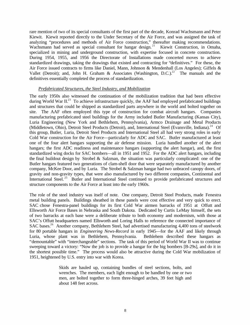
The role of the steel industry was itself of note. One company, Detroit Steel Products, made Fenestrametal building panels. Buildings sheathed in these panels were cost effective and very quick to erect.SAC chose Fenestra-panel buildings for its first Cold War airmen barracks of 1951 at Offutt andEllsworth Air Force Bases in Nebraska and South Dakota. Dedicated by Curtis LeMay himself, the setsof two barracks at each base were a deliberate tribute to both economy and modernism, with those atSAC’s Offutt headquarters named Ellsworth and Loring Halls to reference the connected importance ofSAC bases.26 Another company, Bethlehem Steel, had advertised manufacturing 4,400 tons of steelworkfor 80 portable hangars in Engineering News-Record in early 1945—for the AAF and likely throughLuria, whose plant was in Bethlehem, Pennsylvania. Bethlehem described these hangars as“demountable” with “interchangeable” sections. The task of this period of World War II was to continuesweeping toward a victory: “Now the job is to provide a hangar for the big bombers [B-29s], and do it inthe shortest possible time.” The process would also be attractive during the Cold War mobilization of1951, heightened by U.S. entry into war with Korea.
Skids are hauled up, containing bundles of steel sections, bolts, andwrenches. The members, each light enough to be handled by one or twomen, are bolted together to form three-hinged arches, 39 feet high andabout 148 feet across.

9
Gin poles set up the arches, and connect them together with sway framesand purlins. Steel sheets serve as roof covering and tarpaulins as endwalls.27
And yet a third company, Pacific Iron and Steel of Los Angeles, was responsible for a transitional, variantdouble-cantilever B-36 hangar built, at most, only twice—once at Kirtland Air Force Base in NewMexico, and likely a second time in French Morocco—both instances in 1951 and both connected tostrategic locations critically associated with atomic bomb storage.28 The three steel companies, Detroit,Bethlehem, and Pacific, covered the U.S. coast to coast.
Other major conditions of the early 1950s supported the initial turn to prefabricated steel structures. First,and foremost, was the need for speed due to the onset of the Korean War in June 1950 (and its escalationwith the entry of Communist Chinese troops in November)—compounded through the beginnings of atrue nuclear arms race, with President Truman ordering the development of the hydrogen bomb in January1950 and authorizing an expansion of atomic bomb stockpiling in October. Additional conditions,though, were equally favorable toward steel mobilization construction: cement shortages affectingreinforced concrete construction from 1947 into 1957 (directly counterpointed by the resurgence in theavailability of steel following shortages in the industry due to military construction);29 military fundingpriorities for aircraft and weapons systems; and the sheer fluidity of strategic and tactical planning—where the new installations were thought to be most crucial. The Detroit Steel Products Company’sFenestra panels, used by SAC for its premier airmen dormitories, were also specifically engineered for“earthquake, wind and bomb-resistance” as a part of non-self-framing buildings.30
The Major Commands and Second Generation Infrastructure
The Air Force added significant infrastructure to its Cold War real property during the 1950s, rangingfrom complete modification of existing World War II bases to the construction of entirely newinstallations—the latter especially noteworthy across the northernmost tier of the U.S. Expansion of thebuilt environment mirrored strategic and tactical needs generally, and progressively improved jet aircraft;weapons technologies, storage, and security; and, communications and surveillance systems.31
ADC and TAC
Immediately following the initial Soviet fission device test and emergence of a Red China in late 1949,and the crossing of the North Korean military into South Korea on 25 June 1950, ADC began to addressits lack of infrastructure seriously. The command began to construct the Holabird Root & Burgee designsfor the 85 AC&W radar stations and their accompanying command and control. One of the first of theinitial command and control stations—monitoring one of the 11 continental U.S. air defense regions—was that at McChord Air Force Base, near Tacoma-Seattle, Washington, under construction as of 1951.During 1954 and 1955, ADC expanded this first command and control system to 16 stations, continuingto use the 1949 Holabird Root & Burgee drawings. The American air defense system of the 1950s wastiered: numerous radar stations tracked the skies, supported by a civilian ground observer corps whoscanned for low-flying bombers with binoculars and manned telephones in Operation Skywatch. The firstcompleted permanent radar stations of late 1952 still had the coverage problems associated with theWorld War II heavy radar equipment reused in the Lashup network of the late 1940s. After 1953, low-altitude stations, gap-fillers, surveyed the 5,000-to-200-foot range, and as the decade progressed the airdefense shield came to include northern early-warning systems: the Pinetree Line, the Mid-Canada(McGill) Line, the Distant Early Warning (DEW) Line, and the White Alice Communications System(WACS). The radar network became even more comprehensive with Navy radar picket ships, mannedAtlantic Ocean stations (the Texas Towers), and early-warning patrol aircraft (the EC-121 Warning Star).At the command and control stations, ADC personnel mapped the reports and maintained the ability toauthorize fighter aircraft at regional Air Force bases to check out, intercept, or escort what wereinterpreted as Soviet bombers.

10
Directly complementing the ADC radar, and command and control, network were the alert hangars for thefighter aircraft, with distinctive alert aprons. ADC alert hangars were an extremely interestingphenomenon. Initial construction was in early 1951, with two main types going in placesimultaneously—a Butler mobilization type four-pocket hangar and a permanent four-pocket hangardesigned by the New York architectural-engineering firm Strobel & Salzman. The gable-roofed Butlerbuilding, with a distinctive clam-shell door, harkens back to World War II Butler hangar designs. Theflat-roofed Strobel & Salzman building represents an entirely new approach. ADC introduced a secondgeneration, substantially enlarged alert hangar in 1956-1957 to accommodate the longer and taller fighterjets, also modifying both the Butler and the Strobel & Salzman first generation hangars. The successivenew fighter jets also required runway lengthening throughout the decade, from the initial 5,000-to-7,000-foot runways in 1951 to 8,000, 9,000, 11,000, and 13,000 feet by 1957. In rare cases, ADC supported adouble-squadron, eight-pocket alert hangar at an installation, of both the Butler and Strobel & Salzmantypes. Clusters of support structures accompanying the ADC alert hangar at the flightline includedreadiness and maintenance hangars (three successive generations, 1951, 1953, and 1956); ready shelters(1956); munitions storage, checkout, and assembly structures (three types, 1951, 1954, 1956-1958); areadiness crew dormitory; squadron operations; and a flight simulator. Two other prefabricated steel alerthangars supported the air defense mission at a few locations in the U.S. and overseas.
The 1950s Cold War evolution towards advanced delivery systems for both tactical and strategicweapons, with an emphasis on radar surveillance and standing alerts for air defense, focused onincreasingly sophisticated command and control. Immediately following World War II, scientistsworking in university laboratories were aware that accurate data handling was at the threshold of change.Scientists understood that computer technology could support radar and other communications,interpreting, processing, and disseminating information with new speed. University-based air defensecomputer research at the Massachusetts Institute of Technology, the University of Illinois, and theUniversity of Michigan from 1950 through 1953 led to a computerized air defense network, the semi-automatic ground environment (SAGE). Although SAGE had been planned as the brains of an airdefense web protecting against both bombers and ICBMs, only aircraft detection was possible as-built.Costs were horrific and ADC downscaled the project several times as construction went forward.International Business Machines (IBM) manufactured the computer system for SAGE. The Air Forceabandoned its initial ideas to adapt the Holabird Root & Burgee command and control network directlyfor SAGE: the computer equipment was too just large, and required extensive refrigeration for itsoperation.
Tiered to Western Electric, the architectural-engineering firm Burns & Roe of New York designed theinfrastructure for combat and direction centers, and for accompanying power stations. SAGE allowed afour-fold increase in considered air defense scenarios, and in aircraft-weapons deployment—making itpossible and desirable to shift the air battle to the wing level. ADC put 23 direction centers in place at thesubsector level, leaving the task of higher decisions for only three locations in the west (McChord AirForce Base), in mid-America (Truax Air Force Base, Madison, Wisconsin), and in the east (Syracuse AirForce Base, New York). The three combat centers were combined at installations also sustainingdirection centers, and sometimes at installations having the first generation manual command and controlcenters designed in 1949. SAGE direction and combat centers represented a maturation of the earlierAC&W system. The SAGE direction center at McGuire Air Force Base in New Jersey was the first of thenetwork to be operational, in mid-1958. The remainder of the command and control web was complete inearly 1960.
Changes in the projected methods of Soviet attack, due to the probability of a shift to reliable ICBMs bythe early 1960s, nearly eclipsed the sophistication of SAGE. During 1959 the Joint Chiefs of Staffauthorized true hardening of the North American Air Defense (NORAD) Command Operations Center(COC) then at Ent Air Force Base in Colorado, with new facilities constructed at Cheyenne Mountain,outside Colorado Springs (although construction remained uncompleted until 1966). In an attempt toharden the critically exposed SAGE direction centers, and the three finished SAGE combat centers, ADC

11
briefly planned for 10 Super Combat Centers (SCCs). ADC planned the SCCs as below groundstructures, with smaller, upgraded computers. Outpaced by the evolving world situation, ADC cancelledthe SCC program. Throughout the 1950s, the numbers and jurisdiction of both the air defense regionsand the supportive fighter-interceptor squadrons changed continuously. Increased emphasis focused onplanning for long-range, early warning surveillance radars after the Soviet launching of Sputnik in 1957.The Ballistic Missile Early Warning System (BMEWS) began construction in 1958 at Clear, Alaska;Thule, Greenland; and, Fylingdales Moor, Great Britain. From this point onward, early warning radarswere intimately linked with ballistic missile defense and were the bedrock infrastructure, along with theadvancing ICBM systems themselves, for what can be described as the second half of the Cold War.
SAC
At the outset of the 1950s, SAC was only at the threshold of its Cold War buildup. Curtis LeMay, thenLieutenant General, took over the command in late 1948, moving SAC headquarters from nearWashington, D.C., at Andrews Air Force Base, to Offutt near Omaha. LeMay interpreted Offutt AirForce Base, in the central U.S., as a more protected location than one near the nation’s capitol. SAC’sfirst bombers were primarily World War II B-29s, with the B-50 and B-36 arriving in the SAC inventoryduring 1948 and 1949. In 1950 SAC had about 1,000 total aircraft—a figure that would triple by 1959,paralleling an increase in personnel strength from 85,000 to 262,000. 32 As was true for ADC, SACreceived the funding it required for expansion directly due to the outbreak of the Korean War and to theheightened arms race with the Soviet Union, although SAC was well on its way in the late 1940s. In thedesign and engineering of its infrastructure, SAC, even more than ADC, responded to the shiftingdynamics of planning for a possible war. As of about 1951, SAC organized its future bases in concentricrings focused on distances from Moscow and with the outermost ring 4,600 nautical miles from thesymbolic target (Map 1).33 SAC’s first key bases were those across the West, Southwest, lower Midwest,and South. Yet even as these bases geared up, SAC’s strategy changed. Installations sited and built fromscratch were underway across the upper tier of states just below the Canadian border, and heavilyconcentrated in New England, with other pre-existing AAF locations completely modernized. “Bomberstaking off from New England instead of New Mexico, for instance, could reach their targets more quicklyand with fewer refuelings or stops, since they would be closer to begin with.”34 Installations withunobstructed runways of 12,000 to 13,000 feet, whose pavement was the outcome of significantexperimentation for the weight of the very heavy B-36, and soon the B-52 and the KC-135 tanker,became the centerpieces of the command.
Simultaneously, SAC established itself as a global military arm. The Air Force inherited World War IIoverseas bases from the AAF in Asia, Alaska, Newfoundland, Germany, Great Britain, Bermuda, theAzores, Libya and Saudi Arabia. At certain of these locations, SAC built up a Cold War presence. Yetkey to its plans for strategic second strike capabilities, SAC needed significant new sites. With planningunderway in 1948, SAC focused on North Africa—specifically French Morocco—for a large presence ofmen, rotating aircraft, training, and nuclear weapons depots. Morocco installations went in at the fourlocations of Nouasseur, Sidi Slimane, Benguerir, and Boulhaut (with a fifth intended at El Djema Sahim).By mid-decade SAC had accompanying refueling bases, supported by a huge oil pipeline project with fueltank farms, in progress in lower Spain at Torrejon, Zaragoza, and Moron. Morocco, in particular, isimportant due to construction there during the transitional years of 1951-1953. Immediately followingthe work in Morocco, SAC undertook bases in Newfoundland, Labrador, and Greenland, with those atThule and Goose Bay significant for their role not just for SAC, but also for ADC.35 Early in the 1950s,SAC developed a reflex operation between its southern bases and Morocco, with B-36 and B-47 wingsrotating to North Africa for extended temporary duty. During the middle and late 1950s, SAC adopted adispersal program—spreading out its potential as a Soviet target by placing its aircraft, weapons, andpersonnel on many more bases, with each bombardment wing having two additional installations to whichit could disperse.36
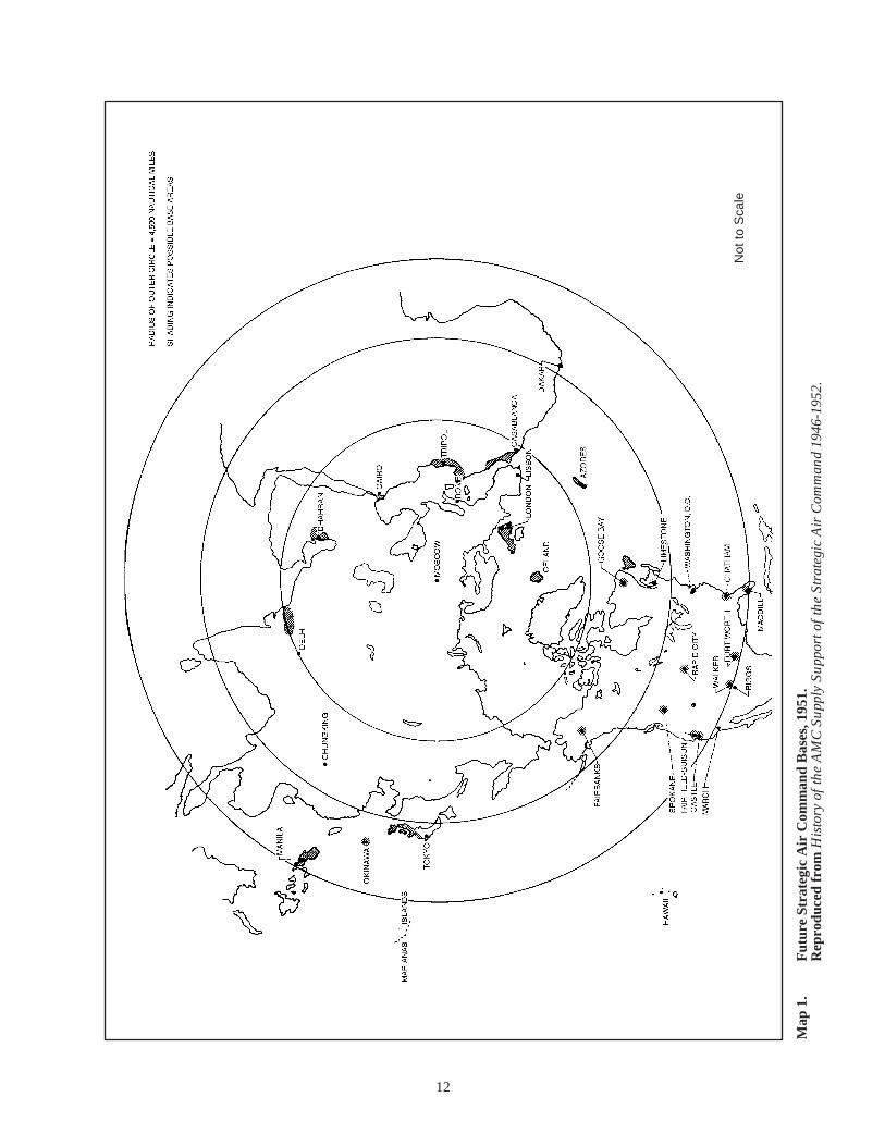
12
Map
1.
Fut
ure
Stra
tegi
c A
ir C
omm
and
Bas
es, 1
951.
R
epro
duce
d fr
om H
isto
ry o
f th
e A
MC
Sup
ply
Supp
ort o
f th
e St
rate
gic
Air
Com
man
d 19
46-1
952.
Not
to S
cale
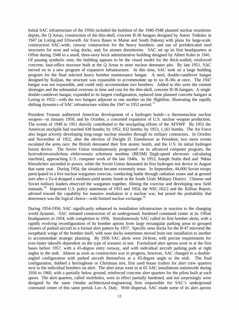
13
Initial SAC infrastructure of the 1950s included the buildout of the 1946-1948 planned nuclear munitionsdepots, the Q Areas; construction of the thin-shell, concrete B-36 hangars designed by Anton Tedesko in1947 (at Loring and Ellsworth Air Force Bases in Maine and South Dakota) with plans for large-scaleconstruction SAC-wide; runway construction for the heavy bombers; and use of prefabricated steelstructures for nose and wing docks, and, for airmen dormitories. SAC set up its first headquarters atOffutt during 1948 in a small, three-story brick administrative building designed by Albert Kahn in 1941.Of passing symbolic note, the building appears to be the visual model for the thick-walled, reinforcedconcrete, faux-office structure built at the Q Areas to store nuclear detonator pits. By late 1951, SACmoved on to a new program of expansive infrastructure. At this time, SAC took on a large buildingprogram for the final selected heavy bomber maintenance hangar. A steel, double-cantilever hangardesigned by Kuljian, the structure was expansible to accommodate up to six B-36s at once. The 1947hangar was not expansible, and could only accommodate two bombers. Added to this were the cementshortages and the substantial overruns in time and cost for the thin-shell, concrete B-36 hangars. A singledouble-cantilever hangar, expanded to its largest configuration, replaced nine planned concrete hangars atLoring in 1952—with the two hangars adjacent to one another on the flightline, illustrating the rapidlyshifting dynamics of SAC infrastructure within the 1947 to 1952 period.37
President Truman authorized American development of a hydrogen bomb—a thermonuclear nuclearweapon—in January 1950, and by October, a concerted expansion of U.S. nuclear weapon production.The events of 1949 to 1951 directly contributed to the stockpiling efforts of the AFSWP. By 1951 theAmerican stockpile had reached 438 bombs; by 1952, 832 bombs; by 1953, 1,161 bombs. The Air Forcealso began actively developing long-range nuclear missiles through its military contractors. In Octoberand November of 1952, after the election of Dwight D. Eisenhower as President, two more eventsescalated the arms race: the British detonated their first atomic bomb, and the U.S. its initial hydrogenfusion device. The Soviet Union simultaneously progressed on its advanced computer program, thebystrodeistvuiushchaia elektronnaia schetnaia mashina (BESM) [high-speed electronic calculatingmachine], approaching U.S. computer work of the late 1940s. In 1953, Joseph Stalin died and NikitaKhrushchev ascended to power, while the Soviet Union detonated its first hydrogen test device in Augustthat same year. During 1954, the situation became extremely tense. In September, 44,000 Soviet troopsparticipated in a live nuclear wargames exercise, conducting battle through radiation zones and at groundzero after a Tu-4 dropped a medium-yield atomic bomb in the South Urals Military District. Chinese andSoviet military leaders observed the wargames together, filming the exercise and developing new fieldmanuals.38 Important U.S. policy statements of 1953 and 1954, the NSC-162/2 and the Killian Report,advised toward the capability for massive retaliation in a nuclear war, but posed the probability thatdeterrence was the logical choice—with limited nuclear exchange.39
During 1954-1956, SAC significantly enhanced its installation infrastructure in reaction to the changingworld dynamic. SAC initiated construction of an underground, hardened command center at its Offuttheadquarters in 1954, with completion in 1956. Simultaneously SAC called its first bomber alerts, with arapidly evolving reconfiguration of its bomber aprons from large rectangular parking areas to groupedclusters of parked aircraft to a formal alert pattern by 1957. Specific nose docks for the B-47 mirrored thesweptback wings of the bomber itself, with nose docks sometimes moved from one installation to anotherto accommodate strategic planning. By 1956 SAC alerts were 24-hour, with precise requirements forever-faster takeoffs dependent on the type of scenario in test. Formalized alert aprons went in at the firstbases before 1957, with a 45-degree entry runway, and with individual aircraft parking pads at rightangles to the stub. Almost as soon as construction was in progress, however, SAC changed to a double-angled configuration with parked aircraft themselves at a 45-degree angle to the stub. The finalconfiguration, dubbed a herringbone or Christmas tree, first used house trailers for alert crew quartersnext to the individual bombers on alert. The alert areas went in at 65 SAC installations nationwide during1956 to 1960, with a partially below ground, reinforced concrete alert quarters for the pilots built at eachapron. The alert quarters, called moleholes, were in effect partially hardened, and not surprisingly weredesigned by the same Omaha architectural-engineering firm responsible for SAC’s undergroundcommand center of this same period, Leo A. Daly. With dispersal, SAC made some of its alert aprons

14
bomber-only and some tanker. By the early 1960s bombers and tankers were sometimes on alert at asingle installation—with tanker pens in addition to the Christmas tree configuration, and with housetrailers again brought to the tarmac.
SAC’s infrastructure was symbolic as well as functional. From the large program for the double-cantilever maintenance hangars of 1951-1955, to the Christmas trees and moleholes, to its undergroundcommand and control center and the simultaneously expanding ICBM program, SAC made its presencevisible and known. Unlike ADC and TAC, SAC also told the world—certainly the Soviet Union—aboutitself. Three times Hollywood made SAC and Curtis LeMay the subject of widely popular films. In1954, Strategic Air Command, with actor James Stewart, showcased the B-36 and the B-47. In 1962, AGathering of Eagles, starring actor Rock Hudson, depicted SAC alerts, using the molehole and alert apronat Beale Air Force Base in Northern California. And in 1964, director Stanley Kubrick made Dr.Strangelove, based on a SAC-gone-awry portrait in a British novel titled Red Alert (of 1958). Even thepopular writer Tom Clancy would comment in The Sum of All Fears of 1991 that SAC’s secondgeneration underground command center at Offutt Air Force Base—also designed by Leo A. Daly, in1984-1989—was commissioned not to replace an obsolete 30-year old center of the middle 1950s, butbecause SAC needed to match the imagery of Hollywood. 40 While not really the case, the Cold Warbuildings and structures of 1950s SAC did in fact project a powerful picture.
After 1960
During the later 1950s and into the 1960s the dynamics of the Cold War altered dramatically with theadvent of deployable ICBMs. As these unmanned nuclear weapons became more reliable, of greaterrange, and smaller, military planning evolved accordingly. SAC activated the first Thor intermediaterange ballistic missiles (IRBMs) and Atlas ICBMs at Vandenberg Air Force Base in Southern Californiain 1958. The next year, SAC undertook Project Big Star, planning rail-mobile deployment for theMinuteman I ICBM, then still in research and testing. Each of the IRBM and ICBM programs requiredlarge-scale infrastructure, with ancillary support, particularly checkout and assembly buildings. Firstemplacements of Atlas and Titan ICBMs governed dynamics into the middle 1960s, followed byemplacements of the Minuteman I series. Command and control facilities for squadrons of missile siloswere hardened underground and manned. Following the Cuban missile crisis in October 1962, the Post-Attack Command and Control System (PACCS) augmented the SAC Looking Glass airborne commandand control unit at Offutt Air Force Base that had been initiated in 1960. A National Emergency AirborneCommand Post (NEACP) also went in place at Andrews Air Force Base near Washington, D.C., and SACdispersed three support squadrons to Westover (Massachusetts), Barksdale (Louisiana), and March(California). PACCS used modified KC-135s capable of carrying personnel, cargo, and intelligenceplatforms.
By 1965, the Air Force assumed that a Soviet first strike would be ICBM in character, but would befollowed by a second bomber strike, and would require a combined bomber and ICBM retaliation. Toaccommodate improved computerized command and control, ADC built the Backup Interceptor Control(BUIC) system, physically adapting selected Holabird Root & Burgee AC&W radar stations for thispurpose. Like SAGE, BUIC came on in stages. BUIC I was manual, operational in 1962-1963 at 27former AC&W radar sites. By 1966, when the 14 BUIC IIs were all on line, including a training facility,only 13 SAGE complexes remained active. SAGE was further reduced to only six installations by 1970.The SAGE/BUIC facilities continued to monitor aircraft approaches, and were never ICBM early warningsources. In 1966 also, the Soviet Union deployed an ABM system protecting Moscow, and nuclear fearsescalated further. The U.S. followed with announcements of its development of multiple independentlytargetable re-entry vehicles (MIRVs) designed to overpower the Soviet ABM system, and with theemplacement of the Minuteman II series. In 1969, the U.S. deployed American ABM and large phased-array radar technologies—in development since the late 1950s—as the Safeguard Site in North Dakotaand as the AN/FPS-85 radar at Eglin Air Force Base in Florida, the latter in development since 1962.
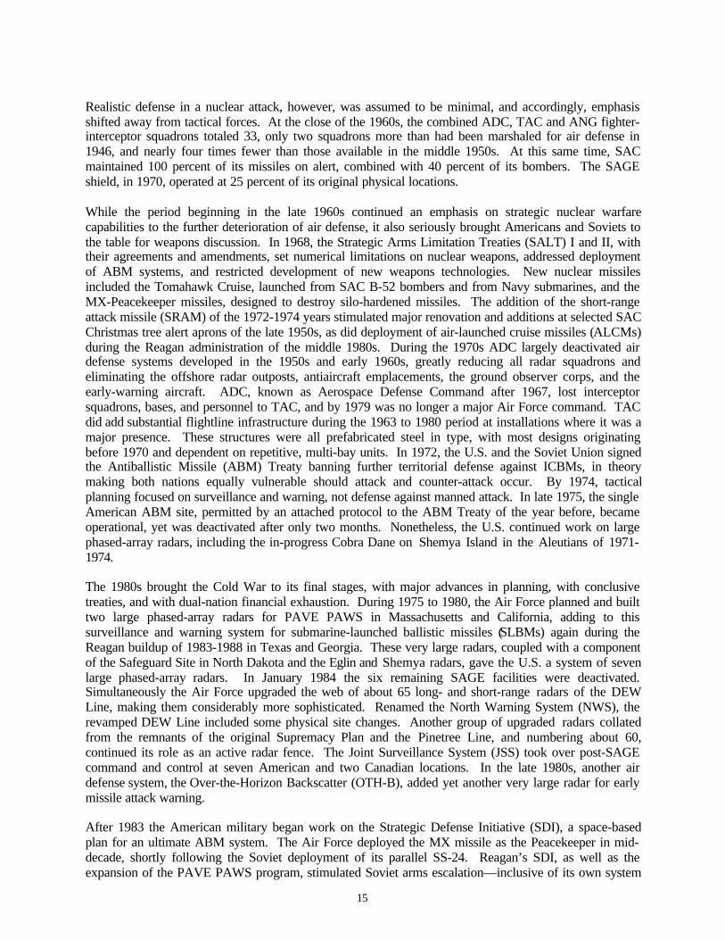
15
Realistic defense in a nuclear attack, however, was assumed to be minimal, and accordingly, emphasisshifted away from tactical forces. At the close of the 1960s, the combined ADC, TAC and ANG fighter-interceptor squadrons totaled 33, only two squadrons more than had been marshaled for air defense in1946, and nearly four times fewer than those available in the middle 1950s. At this same time, SACmaintained 100 percent of its missiles on alert, combined with 40 percent of its bombers. The SAGEshield, in 1970, operated at 25 percent of its original physical locations.
While the period beginning in the late 1960s continued an emphasis on strategic nuclear warfarecapabilities to the further deterioration of air defense, it also seriously brought Americans and Soviets tothe table for weapons discussion. In 1968, the Strategic Arms Limitation Treaties (SALT) I and II, withtheir agreements and amendments, set numerical limitations on nuclear weapons, addressed deploymentof ABM systems, and restricted development of new weapons technologies. New nuclear missilesincluded the Tomahawk Cruise, launched from SAC B-52 bombers and from Navy submarines, and theMX-Peacekeeper missiles, designed to destroy silo-hardened missiles. The addition of the short-rangeattack missile (SRAM) of the 1972-1974 years stimulated major renovation and additions at selected SACChristmas tree alert aprons of the late 1950s, as did deployment of air-launched cruise missiles (ALCMs)during the Reagan administration of the middle 1980s. During the 1970s ADC largely deactivated airdefense systems developed in the 1950s and early 1960s, greatly reducing all radar squadrons andeliminating the offshore radar outposts, antiaircraft emplacements, the ground observer corps, and theearly-warning aircraft. ADC, known as Aerospace Defense Command after 1967, lost interceptorsquadrons, bases, and personnel to TAC, and by 1979 was no longer a major Air Force command. TACdid add substantial flightline infrastructure during the 1963 to 1980 period at installations where it was amajor presence. These structures were all prefabricated steel in type, with most designs originatingbefore 1970 and dependent on repetitive, multi-bay units. In 1972, the U.S. and the Soviet Union signedthe Antiballistic Missile (ABM) Treaty banning further territorial defense against ICBMs, in theorymaking both nations equally vulnerable should attack and counter-attack occur. By 1974, tacticalplanning focused on surveillance and warning, not defense against manned attack. In late 1975, the singleAmerican ABM site, permitted by an attached protocol to the ABM Treaty of the year before, becameoperational, yet was deactivated after only two months. Nonetheless, the U.S. continued work on largephased-array radars, including the in-progress Cobra Dane on Shemya Island in the Aleutians of 1971-1974.
The 1980s brought the Cold War to its final stages, with major advances in planning, with conclusivetreaties, and with dual-nation financial exhaustion. During 1975 to 1980, the Air Force planned and builttwo large phased-array radars for PAVE PAWS in Massachusetts and California, adding to thissurveillance and warning system for submarine-launched ballistic missiles (SLBMs) again during theReagan buildup of 1983-1988 in Texas and Georgia. These very large radars, coupled with a componentof the Safeguard Site in North Dakota and the Eglin and Shemya radars, gave the U.S. a system of sevenlarge phased-array radars. In January 1984 the six remaining SAGE facilities were deactivated.Simultaneously the Air Force upgraded the web of about 65 long- and short-range radars of the DEWLine, making them considerably more sophisticated. Renamed the North Warning System (NWS), therevamped DEW Line included some physical site changes. Another group of upgraded radars collatedfrom the remnants of the original Supremacy Plan and the Pinetree Line, and numbering about 60,continued its role as an active radar fence. The Joint Surveillance System (JSS) took over post-SAGEcommand and control at seven American and two Canadian locations. In the late 1980s, another airdefense system, the Over-the-Horizon Backscatter (OTH-B), added yet another very large radar for earlymissile attack warning.
After 1983 the American military began work on the Strategic Defense Initiative (SDI), a space-basedplan for an ultimate ABM system. The Air Force deployed the MX missile as the Peacekeeper in mid-decade, shortly following the Soviet deployment of its parallel SS-24. Reagan’s SDI, as well as theexpansion of the PAVE PAWS program, stimulated Soviet arms escalation—inclusive of its own system

16
of large phased-array radars. Both the MX and the SS-24 featured MIRVs, with 10 warheads on eachmissile. In 1986 the Soviet SS-24 was rail-mobile. Construction for the American Rail Garrisondeployment immediately followed, occupying the Air Force during 1987 into 1990, returning to the 1959-1960 ideas of Project Big Star for Minuteman I. During the middle 1980s, also, SAC’s program for theB1-B, added major new maintenance facilities and fuel cell docks to the flightlines of selectedinstallations—the first such infrastructure since that designed for the SAC bombers of the 1950s. Thecontinuous military and technological achievements, as well as the extreme costs of the half-century ColdWar, the fall of the Berlin Wall, and the political upheaval in the Soviet Union at the close of the 1980s,led to the Strategic Arms Reduction Treaty (START). Signed in July 1991 by the U.S. and the SovietUnion, START stipulated mutual arsenal reduction by 50 percent, and elimination of all MIRVed ICBMs.Rail Garrison was one of the conclusive bargaining chips of the war.
1 Eugene M. Emme, The Impact of Air Power: National Security and World Politics (Princeton, New Jersey: D. VanNostrand Company, Inc., 1959), v.2 Karen J. Weitze, Guided Missiles at Holloman Air Force Base: Test Programs of the United States Air Force inSouthern New Mexico, 1947-1970 , Holloman Air Force Base Cultural Resources Publication No.5 (El Paso: Geo-Marine, Inc., for Air Combat Command, November 1997), 91-98, 161-184.3 Karen J. Weitze, PAVE PAWS Beale Air Force Base: Historic Evaluation and Context (Sacramento: KEAEnvironmental, Inc., for Air Combat Command, February 1999), 34-37.4 Wolfgang Saxon, “Dr. Bruno Balke, 91, Innovator in Study of Physical Conditioning,” New York Times, 17 June1999, C23.5 As posted on the internet web site: www.wai.com, 23 June 1999.6 Karen J. Weitze, “Der Ring: Social Idealism and the Wartime Transmittal of Technical Information,” abstractsubmitted to the Society of Architectural Historians, “Architecture and Emigration” session, 1997.7 Ivan M. Viest, “Anton Tedesko,” National Academy of Engineering of the United States of America MemorialTributes, volume 8 (Washington, D.C.: National Academy Press, 1996), 262-267; David P. Billington and Eric M.Hines, “Anton Tedesko, Model Research and the Introduction of Thin Shells into the United States,” paper on file atthe Civil Engineering Department, Princeton University.8 X [George F. Kennon], “The Sources of Soviet Conduct,” in Hamilton Fish Armstrong (ed.), The Foreign AffairsReader (Harper & Brothers for the Council on Foreign Relations: New York and London, 1947), 465-483; WalterLippmann, The Cold War: A Study in U.S. Foreign Policy (Harper & Brothers Publishers: New York and London:1947).9 Alfred Goldberg (ed.), A History of the United States Air Force 1907-1957 (Princeton, New Jersey: D. VanNostrand Company, Inc., 1957), 105-110.10 Necah Stewart Furman, Sandia National Laboratories: The Postwar Decade (Albuquerque: University of NewMexico Press, 1990), 207-216, 320-325.11 Karen J. Weitze, Inventories of Cold War Properties: Andrews, Charleston, Dover, Grand Forks, McChord, Scott,and Travis Air Force Bases (Plano, Texas: Geo-Marine, Inc., for Air Mobility Command, 1996), context. Sevenvolumes.12 Furman, Sandia, 307-312, 323-324.13 Arlie C.Huffman, Directorate of Civil Engineering, Development of the Air Force Civil Engineering Function1918 – Present, 5-11. Appended to Headquarters, USAF, History of the Directorate of Civil Engineering, 1 July1962 – 31 December 1962.14 “Office, Assistant Chief of Staff, Installations, Headquarters, United States Air Force,” The Military Engineer 48,no.322 (March-April 1956): 118-119.15 Huffman, Civil Engineering Function, 14.16 “The Directorate of Installations, Headquarters, United States Air Force,” The Military Engineer 50, no.335(May-June 1958): 197-198.17Headquarters, USAF, History of the Directorate of Installations, 1 January 1952 – 30 June 1952, 5.18 Mills & Petticord, mixed references on index cards and as 105mm microfiche copies of drawings, #s: 39-01-30and 39-01-37 (two unbuilt versions, ADC alert hangar—January and March 1951); 39-01-33 and 39-01-39 (twoversions, ADC readiness hangar—January and July 1951); 39-01-27, 39-01-28, 39-01-34, 39-01-35, 39-01-36, 39-01-43, 39-01-44, 39-01-45, 39-01-46, and 39-01-47 (two unbuilt versions, five sizes each, SAC double-cantileverbomber hangar—January/February 1951 and August 1951); 39-05-04 (B-29 and B-50 nose dock—March 1952).19 Headquarters, USAF, History of the Directorate of Installations, 1 January 1953 – 30 June 1953 , ManagementEngineering Group section (not paginated), and, Architectural and Engineering Division section (not paginated).

17
20Headquarters, USAF, History of the Directorate of Installations, 1 July 1953 – 31 December 1953, Architecturaland Engineering Division section, 9.21Headquarters, USAF, History of the Assistant Chief of Staff, Installations, 1 January 1954 to 30 June 1954,Directorate of Construction section (not paginated).22Headquarters, USAF, History of the Assistant Chief of Staff, Installations, 1 July 1955 to 31 December 1955, 72,and, History of the Assistant Chief of Staff, Installations, 1 January 1956 to 30 June 1956 , 54-55.23 Walter G. Hiner, “Combat Airplane Hangars,” The Military Engineer 37, no.235 (May 1945): 185-188.24 “Butler Buildings,” The Military Engineer 43, no.294 (July-August 1951): 19; “Luria Standardized Buildings,”Engineering News-Record 152, no.25 (24 June 1954): 108; “Armco Steelox Buildings,” The Military Engineer 44,no.299 (May-June 1952): 13; Detroit Steel Products, “Fenestra Metal Building Panels,” The Military Engineer 44,no.300 (July-August 1952): 33; Aviation Division, International Steel Company, “Tall Tails are no problem,” TheMilitary Engineer 50, no.335 (May-June 1958): 13.25Weitze, Inventories of Cold War Properties, context, descriptions and analysis.26 “Fenestra Metal Building Panels,” 33; Lori E. Rhodes, Patience Elizabeth Patterson, and Katherine J. Roxlau, ABaseline Inventory of Cold War Material Culture at Offutt Air Force Base, volume II-23 of A Systemic Study of AirCombat Command Cold War Material Culture (Albuquerque: Mariah Associates, Inc., for Air Combat Command,October 1997), 42; “Two Bases for the Biggest Strategic Bombers,” Engineering News-Record 158, no.9 (28February 1957): 42; Karen Lewis, R. Blake Roxlau, and Katherine J. Roxlau, A Baseline Inventory of Cold WarMaterial Culture at Ellsworth Air Force Base, volume II-7 of A Systemic Study of Air Combat Command Cold WarMaterial Culture (Albuquerque: Mariah Associates, Inc., for Air Combat Command, August 1997), A-2, C-9, C-10[Real Property No. 8203; second dormitory mistakenly shown as a photograph for Real Property No. 7806].27 Bethlehem Steel, “Portable Hangars erected on the double,” Engineering News-Record 134, no.12 (22 March1945): 13.28 Air Force Installations Representative, North Atlantic Division, “French Morocco AFIRO Inspection Visit,”November 1951, and map: in Folder “French Morocco AFIRO Inspection Visit,” Box 4, Entry 495, Record Group341, National Archives II, Maryland.29 “Steel vs. Concrete,” Engineering News-Record 142, no.5 (3 February 1949): 43; John P. Chamberlain, “CementShortage Will End in 1957,” Engineering News-Record 155, no.24 (15 December 1955): 21-23.30 Detroit Steel Products Company, “Fenestra Metal Building Panels,” The Military Engineer 44, no.299 (May-June1952): 6.31 Weitze, Inventories of Cold War Properties, context, descriptions and analysis.32 Strategic Air Command, Headquarters: The Progressive Development of the Strategic Air Command 1946-1965 ;“Progressive Development of SAC 1967;” “Progressive Development of SAC 1968-1969;” and “ProgressiveDevelopment of SAC 1970.”33 Mary R. Self, Historical Division, Air Material Command, History of the AMC Supply Support of the Strategic AirCommand 1946-1952 (Wright-Patterson Air Force Base: Air Materal Command, USAF, June 1954), map between148 and 149.34 Goldberg, United States Air Force, 122-123.35 Ibid, 191-193.36 Ibid, 123-124.37 “Limestone Army Airfield Limestone, Maine; Layout Plan of Airfield,” dated before 12 March 1948, withrevision for future hangars stamped May 1948, included in “Construction Report Limestone Air Force BaseLimestone, Maine,” 3 June 1949, in Folder “Limestone AFB Construction Report June 1949,” Box 15, Entry 495,Record Group 341; and, “Limestone Air Force Base Proposed Construction Program,” in Folder “Limestone AFB,Liaison Officers Report August 1950,” Box 16, Entry 495, Record Group 341, National Archives II, Maryland.38 David Holloway, Stalin and the Bomb: The Soviet Union and Atomic Energy 1939-1956 (New Haven andLondon: Yale University Press, 1994), 230, 326-328.39 Karen Lewis, Katherine J. Roxlau, Lori E. Rhodes, Paul Boyer, and Joseph S. Murphey, Historic Context andMethodology for Assessment, volume I of A Systemic Study of Air Combat Command Cold War Material Culture(Albuquerque: Mariah Associates, Inc., for Air Combat Command, December 1995), 27-34.40 Tom Clancy, The Sum of All Fears (New York: Berkley Books, 1991), 715.

18

19
Chapter 2: Evolution of Key Property Types
Plate 1. B-36 at Ellsworth Air Force Base. Hangar, midground. Moveable wing docks, left,background. View of 1953. Courtesy of the Air Force Historical Research Agency.
During the Cold War, the evolution of key property types for SAC bomber infrastructure can be analyzedin eight categories. Of note, these categories are concentrated in the period of Curtis LeMay’s leadershipof SAC, 1946/1947 to 1957, with a subsequent appearance of significant new design and engineeringduring the Carter, Reagan, and Bush presidencies, 1976-1991. Upon the completion of constructionprograms begun in the late 1950s, design and engineering for SAC bomber infrastructure is largely staticfor a full quarter century. After about 1960, SAC reused or adapted many pre-existing structures toaccommodate added bomber missions, and did so primarily due to introduced weapons systems—paralleling the exceptionally long life of the B-52 bomber and KC-135 refueling tanker. Discussionsbelow focus on operational buildings and structures, inclusive of runway pavements and aircraft parkingapron configurations. Not generally addressed is cantonment architecture, such as administrative,engineering, and office buildings; airmen and officer housing; base entertainment and shoppingcomplexes; medical facilities; schools; churches; general aircraft maintenance and repair infrastructure;and generic support units. On occasion, cantonment architecture built during the Cold War can bedirectly tied to the bombing mission of SAC, rather than to the Air Force-wide expansion of installationinfrastructure in support of a large U.S. military during these years. These latter cases will be includedbelow.
The categories presented are arranged by property type, and are discussed in an overall chronologicalformat, with a minimum of overlapping years as the analysis moves from one property type to another(Plate 1). Categories are (1) the first generation maintenance hangar for the B-36, 1947-1950; (2) thesecond generation maintenance hangar for the B-36, B-47, and B-52, 1951-1955; (3) prefabricated,mobilization infrastructure, including wing docks and, steel-panel airmen dormitories, 1948-1956; (4)pavement experimentation at selected runways for the B-36 and the B-52, 1948-1956; (5) Q Areas, 1947-1956; (6) alert apron configurations and crew quarters, 1954-1959; (7) first generation headquarters

20
command post, below ground, and the Offutt chapel, 1954-1957; and (8) infrastructure of the late 1970s,and again during the Reagan-Bush years, including a maintenance hangar for the airborne command post;a hangar for the B-1 and aircraft shelters for the B-2; and, the second generation undergroundheadquarters command and control center.
First Generation Maintenance Hangar for the B-36
With the establishment of SAC in March 1946, the aircraft inventory for command’s bombardmentgroups included B-29s, B-17s, and even a few B-25s. Only the B-29 was not obsolete, yet this bombercould not attack intercontinental targets from the continental U.S.—making SAC’s long-range bombingcapabilities all but nonexistent. Additionally, in May 1946, the Army Air Forces (AAF) gave SAC theresponsibility of delivering the atomic bomb. Only one of the command’s bombardment units, the 509th
at Walker Air Force Base (then Roswell Field) in New Mexico, was trained and ready for the atomicbomb mission. Walker, and Kirtland to the north in Albuquerque, would quickly become the basesaround which this mission first centered, although with the move of SAC’s headquarters from Andrews toOffutt in 1948 plans for the initial flightline infrastructure associated with this mission shifted toEllsworth and Loring, in South Dakota and Maine, respectively. Loaded with an atomic bomb, the B-29,soon paired with its updated version the B-50 (with greater speed and longer combat radius), andparalleled by the Soviets through the Tu-4, were the first Cold War bombers. While the B-29, B-50, andTu-4 were the long-range aircraft that revolutionized air war, the aircraft could only fly the U.S.-Sovietcorridor one way, and could not achieve that distance heavily loaded. Hangars and flightline ancillarystructures for SAC’s B-29 and B-50 carried over from World War II, with the exception of added wingdocks immediately before 1950.
SAC commanders, particularly Curtis LeMay who was known for his “single-mindedness of purpose andiron resolution,”1 realized early that a truly intercontinental bomber, effective in a retaliatory nuclearattack against the Soviet Union, would need considerably more range. The AAF had contracted with apredecessor of Convair, Vultee Aircraft, for the B-36 Peacemaker in 1941. At that time the Armyrealized that Europe might be lost as a staging ground for combat, and that an aircraft capable of flying around trip from American continental bases, with aerial refueling, was needed. As Convair developed thevery heavy bomber in the immediate post-World War II years, designing the aircraft to carry nuclearpayloads and to make the transition from a propeller- to a jet-engine plane, the B-36 was still highlyexperimental in its primary mission. Driven by six engines, the B-36 came into the SAC inventory in late1948, with three operational heavy bombardment wings of B-36s available at the close of 1949 (Plate 2).Eleven wings of B-29s and B-50s still constituted the majority of SAC aircraft—from this point forwardreclassed as medium, rather than heavy, bombers.
Just before the turn of 1951, supported by the mobilization for the Korean War after June 1950, SAC had38 B-36s deployed to its bases. Unwieldy planes with a wingspan of 230 feet, a length of just over 162feet, and a height of nearly 49 feet, the B-36 had an official range of 10,000 miles. Actual range for thebomber was 6,800 to 8,175 miles, with aerial refueling required. When loaded, the B-36 burned fuel at anexorbitant rate. With progressive evolution of the bomb itself, especially from the early atomic bombs ofthe late 1940s to the thermonuclear devices with sealed detonator pits (“wooden” bombs with anindefinite shelf life) of the middle 1950s, even the jet-modified B-36—with its 10 engines—could onlycarry a single bomb. The Mark 17 (Mk 17), a thermonuclear bomb of mid-decade, weighed more than41,000 pounds. The complimentary tanker for the B-36 was the KC-97, a slow propeller-engine aircraftwith a range of only 4,300 miles, also derived from the B-29. The B-36/KC-97 pair necessitated runwayextensions to a minimum of 10,000 feet, with 40 inches of subsurface construction. 2
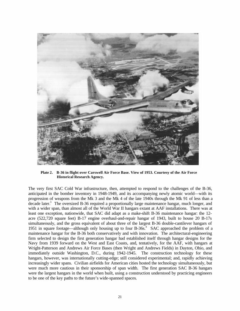
21
Plate 2. B-36 in flight over Carswell Air Force Base. View of 1953. Courtesy of the Air ForceHistorical Research Agency.
The very first SAC Cold War infrastructure, then, attempted to respond to the challenges of the B-36,anticipated in the bomber inventory in 1948-1949, and its accompanying newly atomic world—with itsprogression of weapons from the Mk 3 and the Mk 4 of the late 1940s through the Mk 91 of less than adecade later.3 The oversized B-36 required a proportionally large maintenance hangar, much longer, andwith a wider span, than almost all of the World War II hangars extant at AAF installations. There was atleast one exception, nationwide, that SAC did adapt as a make-shift B-36 maintenance hangar: the 12-acre (522,720 square feet) B-17 engine overhaul-and-repair hangar of 1943, built to house 20 B-17ssimultaneously, and the gross equivalent of about three of the largest B-36 double-cantilever hangars of1951 in square footage—although only housing up to four B-36s.4 SAC approached the problem of amaintenance hangar for the B-36 both conservatively and with innovation. The architectural-engineeringfirm selected to design the first generation hangar had established itself through hangar designs for theNavy from 1939 forward on the West and East Coasts, and, tentatively, for the AAF, with hangars atWright-Patterson and Andrews Air Force Bases (then Wright and Andrews Fields) in Dayton, Ohio, andimmediately outside Washington, D.C., during 1942-1945. The construction technology for thesehangars, however, was internationally cutting-edge; still considered experimental; and, rapidly achievingincreasingly wider spans. Civilian airfields for American cities hosted the technology simultaneously, butwere much more cautious in their sponsorship of span width. The first generation SAC B-36 hangarswere the largest hangars in the world when built, using a construction understood by practicing engineersto be one of the key paths to the future’s wide-spanned spaces.
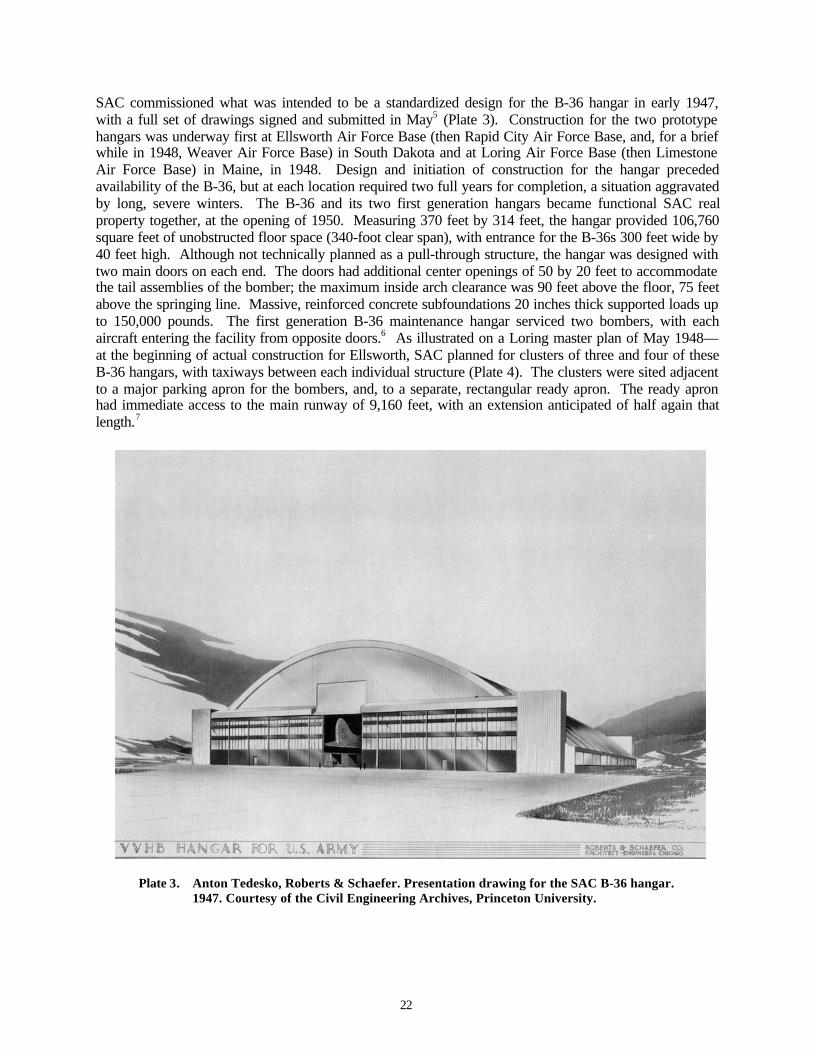
22
SAC commissioned what was intended to be a standardized design for the B-36 hangar in early 1947,with a full set of drawings signed and submitted in May5 (Plate 3). Construction for the two prototypehangars was underway first at Ellsworth Air Force Base (then Rapid City Air Force Base, and, for a briefwhile in 1948, Weaver Air Force Base) in South Dakota and at Loring Air Force Base (then LimestoneAir Force Base) in Maine, in 1948. Design and initiation of construction for the hangar precededavailability of the B-36, but at each location required two full years for completion, a situation aggravatedby long, severe winters. The B-36 and its two first generation hangars became functional SAC realproperty together, at the opening of 1950. Measuring 370 feet by 314 feet, the hangar provided 106,760square feet of unobstructed floor space (340-foot clear span), with entrance for the B-36s 300 feet wide by40 feet high. Although not technically planned as a pull-through structure, the hangar was designed withtwo main doors on each end. The doors had additional center openings of 50 by 20 feet to accommodatethe tail assemblies of the bomber; the maximum inside arch clearance was 90 feet above the floor, 75 feetabove the springing line. Massive, reinforced concrete subfoundations 20 inches thick supported loads upto 150,000 pounds. The first generation B-36 maintenance hangar serviced two bombers, with eachaircraft entering the facility from opposite doors.6 As illustrated on a Loring master plan of May 1948—at the beginning of actual construction for Ellsworth, SAC planned for clusters of three and four of theseB-36 hangars, with taxiways between each individual structure (Plate 4). The clusters were sited adjacentto a major parking apron for the bombers, and, to a separate, rectangular ready apron. The ready apronhad immediate access to the main runway of 9,160 feet, with an extension anticipated of half again thatlength.7
Plate 3. Anton Tedesko, Roberts & Schaefer. Presentation drawing for the SAC B-36 hangar.1947. Courtesy of the Civil Engineering Archives, Princeton University.
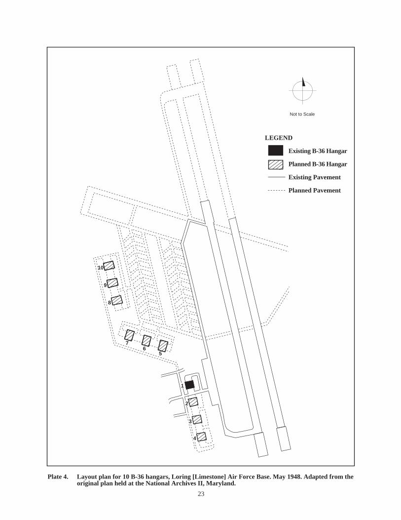
LEGEND
Existing B-36 Hangar
Planned B-36 Hangar
Existing Pavement
Planned Pavement
Plate 4. Layout plan for 10 B-36 hangars, Loring [Limestone] Air Force Base. May 1948. Adapted from the original plan held at the National Archives II, Maryland.
23
10
9
8
76
5
1
2
3
4
Not to Scale

24
Engineer Anton Tedesko, of the Chicago firm Roberts & Schaefer, designed and engineered the firstgeneration B-36 hangar for SAC, drawing upon 20 years of research in thin-shell, reinforced concrete,short-barrel construction. Dr. Tedesko (1903-1994) was born and educated in Vienna, Austria, receivinghis first degree in civil engineering in 1926. From 1926 to 1928 he worked in the U.S. as a “detailer andsteel designer,” then returning to Vienna to assist Ernest Melan, a professor of steel design andconstruction at the Institute of Technology with whom he would later undertake his doctorate. In Vienna,Tedesko also began his life’s work in industrial architecture, hiring with Dyckerhoff & Widmann A.G.[Aktien Gesellschaft (joint-stock company)] in Wiesbaden-Biebrich in 1930. Dyckerhoff & Widmannwere pioneers in reinforced concrete construction, and were renowned as builders of dams, bridges, andtunnels. Dyckerhoff & Widmann had begun analyses and testing for thin-shell, concrete design during1922 to 1930, focused through the work of two firm members, engineers Franz Dischinger (1887-1953)and Ulrich Finsterwalder (1897-1989). Tedesko worked for Dyckerhoff & Widmann for only twoyears—until 1932, but sustained continuous interaction with the firm into the 1940s. In Wiesbaden-Biebrich, Tedesko worked closely with Finsterwalder, in particular, while Finsterwalder and another firmengineer, Hubert Rüsch, finished their analyses on the behavior of shallow, cylindrical, reinforcedconcrete barrel shells. Tedesko participated in the design for the Great Market Hall in Budapest, thefirm’s first large-scale shallow barrel shell, under Finsterwalder, as well as being one of the firm’sengineers who developed the detailed analysis of the thin shell engineered for a large sulfate worksstorage facility in Belgium. 8
The engineers developing and testing the thin-shell, reinforced concrete construction system throughDyckerhoff & Widmann concentrated on aligning theoretical mathematics with practical industrial uses.Dyckerhoff & Widmann had initiated experimentation in 1922 to meet the needs of the Zeiss opticalcompany for a planetarium at the German Museum in Munich, with engineers from both firmsparticipating. This first thin-shell dome was quite small, but featured reinforced concrete only 1.1811inches thick—which was remarkable for its nearly 52.5-foot diameter. The two lead engineers from Zeissand Dyckerhoff & Widmann decided to patent the thin-shell system as Z-D, also alternately known asZeiss-Dywidag [Zeiss Dyckerhoff & Widmann A.G.] construction. With larger scale projects, the twoengineers, Walter Bauersfeld of Zeiss and Franz Dischinger of Dyckerhoff & Widmann, addressed shellbehavior under asymmetric loads, stability against buckling, and overall deflections.9 By the time ofTedesko’s hiring at Dyckerhoff & Widmann, the firm was contracting for thin-shell industrial structuresin Germany, Lithuania, Rumania, Hungary, Belgium, and Italy, including aircraft hangars, a rolling mill,a plant for processing crude industrial benzene (a petroleum distillate), a coal storage silo, a streetcarrepair facility, and several automobile showrooms.10
In 1932 Anton Tedesko immigrated to the U.S., joining the Chicago firm of Roberts & Schaefer under ajoint agreement with Dyckerhoff & Widmann to promote, design, and supervise construction of ZDstructures. Founded in 1896 by Colonel Warren R. Roberts, a civil engineer, as the Warren R. RobertsCompany, Roberts & Schaefer originated as a structural design service for the cement, minerals, and grainindustries of the upper Midwest. Colonel Roberts had formalized the partnership Roberts & Schaefer in1904 with a University of Illinois classmate J.V. Schaefer, who at that time worked for LinkBelt in theircoal washery department. The company, like Dyckerhoff & Widmann, focused on industrialconstruction—particularly processing plants and storage facilities for coal, gold, silver, copper, limestone,cement, aggregate, phosphate, salt, potash, lead, antimony, zinc, zinc oxide, and silica sand.11 Thelicensing agreement between Dyckerhoff & Widmann and Roberts & Schaefer resulted not just from thenatural fit between the two companies, but also directly from an existing connection dating back to themiddle 1920s. Engineer John E. Kalinka (born 1888), like Tedesko Viennese and an engineeringgraduate of the Institute of Technology, had worked in Europe until 1924 as a designer and supervisor formajor highway and railway projects, inclusive of long-span bridges. In 1925 he hired with Roberts &Schaefer.12 Kalinka is thought either to have had a sustained connection to Dyckerhoff & Widmann afterhis immigration, or, to have been a professional associate known to Tedesko through their universityeducation in Vienna. Kalinka was the conduit for Tedesko between Dyckerhoff & Widmann and Roberts& Schaefer.13

25
Tedesko’s joint task for Dyckerhoff & Widmann and Roberts & Schaefer was to sell reinforced concretelong-barrel shell, short-barrel shell, and dome construction in the U.S., with Roberts & Schaefer receivingexclusive American rights to ZD construction after a trial period during which three or four thin-shellstructures would be built. Prior to his arrival in 1932, no such structures had been built outside of thoseby Dyckerhoff & Widmann in Europe, although Engineering News-Record, Western Construction News,Construction Methods, Transactions of the American Society of Civil Engineers, and Architectural Forumhad begun publishing short articles on the innovative technology in 1929-1932. Tedesko immediatelyauthored an article on reinforced concrete shells for the Canadian journal Concrete and Quarry in late1933, with Dyckerhoff & Widmann’s Budapest markethall showcased in the international edition ofArchitectural Forum in early 1934. 14
The Depression in the U.S. at first slowed progress of the German-American ZD enterprise. After beingunsuccessful at winning the contract for the German Pavilion at the Century of Progress World’s Fair inChicago, Roberts & Schaefer finally secured a contract for the long-barrel shell Brook Hill Dairy Farmexhibition hall erected for the second season of the fair in 1934. The Brook Hill Dairy Farm hall allowedRoberts & Schaefer to showcase ZD construction, with Engineering News-Record, Concrete,Architectural Forum, and Architectural Record all illustrating the building and taking professional note.15
Brook Hill featured five parallel, elliptical three-inch shells, each spanning 14 feet with a length of 34feet. The hall is considered the first true multi-span vault in the U.S. Tedesko followed it the same yearwith the design for a thin-shell dome for the Hayden Planetarium in New York. The dome was 81 feet indiameter and of 77-foot height at its crown. Like the Chicago fair building, the planetarium featured athree-inch thick shell. It also marked the first known collaboration between Tedesko and anotherengineering firm that would become prominent in designing specialized structures for the Air Forceduring the early Cold War, Weiskopf & Pickworth of New York.16 Throughout the remainder of the1930s Tedesko continued to establish himself as a significant engineer of thin-shell, reinforced concreteconstruction in the U.S. Prominent commissions included those for the Hershey Sports Arena, inHershey, Pennsylvania, 1935-1936, a short-barrel shell of three-and-one-half inches thickness spanning245 feet; auditoriums in Kansas, Wisconsin, Tennessee, Louisiana; another sports arena for HaverfordCollege, Haverford, Pennsylvania; industrial storage buildings in New York and Pennsylvania; a tire plantin Natchez, Mississippi; and an ice skating rink in Washington, D.C.17
In 1939 Roberts & Schaefer, still with direct support and collaboration by Dyckerhoff & Widmann, begandesigning reinforced concrete thin-shell hangars, armories, engineering and repair shops, foundries, andmunitions warehouses for the U.S. Army and Navy. Following an international congress for reinforcedconcrete in Liege, Belgium, held in September 1930 and subsequently published18, the Nazi military hadalso initiated the adoption of ZD construction—most notably for a flight training school hangar inCottbus, Germany in 1933. The Cottbus hangar collapsed several months after it was built due todeflections caused by excessive creep. Dyckerhoff & Widmann had used too few stiffening ribs along thelength of the vault (spaced at just over 131 feet), although it had previously designed hangars successfullyin Turin, Prague, Great Britain, and Cairo. 19 Although Roberts & Schaefer’s first U.S. militarycommission did not occur until the end of the decade, engineer Ulrich Finsterwalder (Dyckerhoff &Widmann) had actively collaborated with Anton Tedesko (after his arrival at Roberts & Schaefer) inproposing American hangars and engineering shops as early as November 1932, with documentedcorrespondence in German for airfield shops in Portland, Oregon. Similar, but more lengthy,correspondence exists as of July 1939 for Navy seaplane hangars in San Diego, California.20 During1937, Eric C. Molke, an engineering graduate of the University of Vienna, also joined Roberts &Schaefer, becoming manager of the Washington, D.C., Roberts & Schaefer office—a position assumed byTedesko during World War II.21 In January-February 1940, John Kalinka authored a dramatic article onZD hangars for The Military Engineer, the official journal of the U.S. Army Corps of Engineers, in whichhe illustrated four single- and multiple-barrel thin-shell concrete hangars recently completed outside theU.S.22 (Plate 5). At about this same time, Dyckerhoff & Widmann’s Franz Dischinger consulted forOrganization Todt—the Third Reich’s equivalent of the U.S. Army Corps of Engineers. Named for Dr.
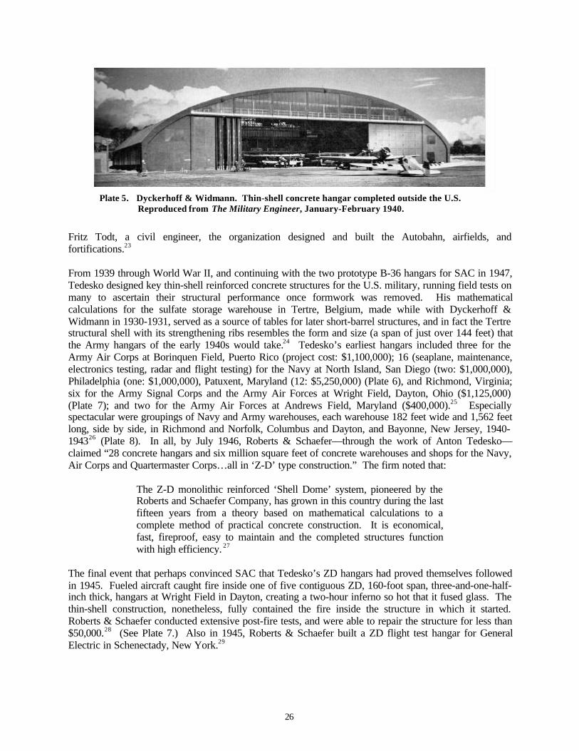
26
Plate 5. Dyckerhoff & Widmann. Thin-shell concrete hangar completed outside the U.S.Reproduced from The Military Engineer, January-February 1940.
Fritz Todt, a civil engineer, the organization designed and built the Autobahn, airfields, andfortifications.23
From 1939 through World War II, and continuing with the two prototype B-36 hangars for SAC in 1947,Tedesko designed key thin-shell reinforced concrete structures for the U.S. military, running field tests onmany to ascertain their structural performance once formwork was removed. His mathematicalcalculations for the sulfate storage warehouse in Tertre, Belgium, made while with Dyckerhoff &Widmann in 1930-1931, served as a source of tables for later short-barrel structures, and in fact the Tertrestructural shell with its strengthening ribs resembles the form and size (a span of just over 144 feet) thatthe Army hangars of the early 1940s would take.24 Tedesko’s earliest hangars included three for theArmy Air Corps at Borinquen Field, Puerto Rico (project cost: $1,100,000); 16 (seaplane, maintenance,electronics testing, radar and flight testing) for the Navy at North Island, San Diego (two: $1,000,000),Philadelphia (one: $1,000,000), Patuxent, Maryland (12: $5,250,000) (Plate 6), and Richmond, Virginia;six for the Army Signal Corps and the Army Air Forces at Wright Field, Dayton, Ohio ($1,125,000)(Plate 7); and two for the Army Air Forces at Andrews Field, Maryland ($400,000).25 Especiallyspectacular were groupings of Navy and Army warehouses, each warehouse 182 feet wide and 1,562 feetlong, side by side, in Richmond and Norfolk, Columbus and Dayton, and Bayonne, New Jersey, 1940-194326 (Plate 8). In all, by July 1946, Roberts & Schaefer—through the work of Anton Tedesko—claimed “28 concrete hangars and six million square feet of concrete warehouses and shops for the Navy,Air Corps and Quartermaster Corps…all in ‘Z-D’ type construction.” The firm noted that:
The Z-D monolithic reinforced ‘Shell Dome’ system, pioneered by theRoberts and Schaefer Company, has grown in this country during the lastfifteen years from a theory based on mathematical calculations to acomplete method of practical concrete construction. It is economical,fast, fireproof, easy to maintain and the completed structures functionwith high efficiency. 27
The final event that perhaps convinced SAC that Tedesko’s ZD hangars had proved themselves followedin 1945. Fueled aircraft caught fire inside one of five contiguous ZD, 160-foot span, three-and-one-half-inch thick, hangars at Wright Field in Dayton, creating a two-hour inferno so hot that it fused glass. Thethin-shell construction, nonetheless, fully contained the fire inside the structure in which it started.Roberts & Schaefer conducted extensive post-fire tests, and were able to repair the structure for less than$50,000.28 (See Plate 7.) Also in 1945, Roberts & Schaefer built a ZD flight test hangar for GeneralElectric in Schenectady, New York.29

27
Plate 6. Anton Tedesko, Roberts & Schaefer. Hangars for the United States Navy, Patuxent,Maryland. 1942. Courtesy of the Civil Engineering Archives, Princeton University.
Plate 7. Anton Tedesko, Roberts & Schaefer. Hangars for the Army Air Forces, Wright Field.1943-1945. View of September 1999. Photograph, K.J. Weitze.
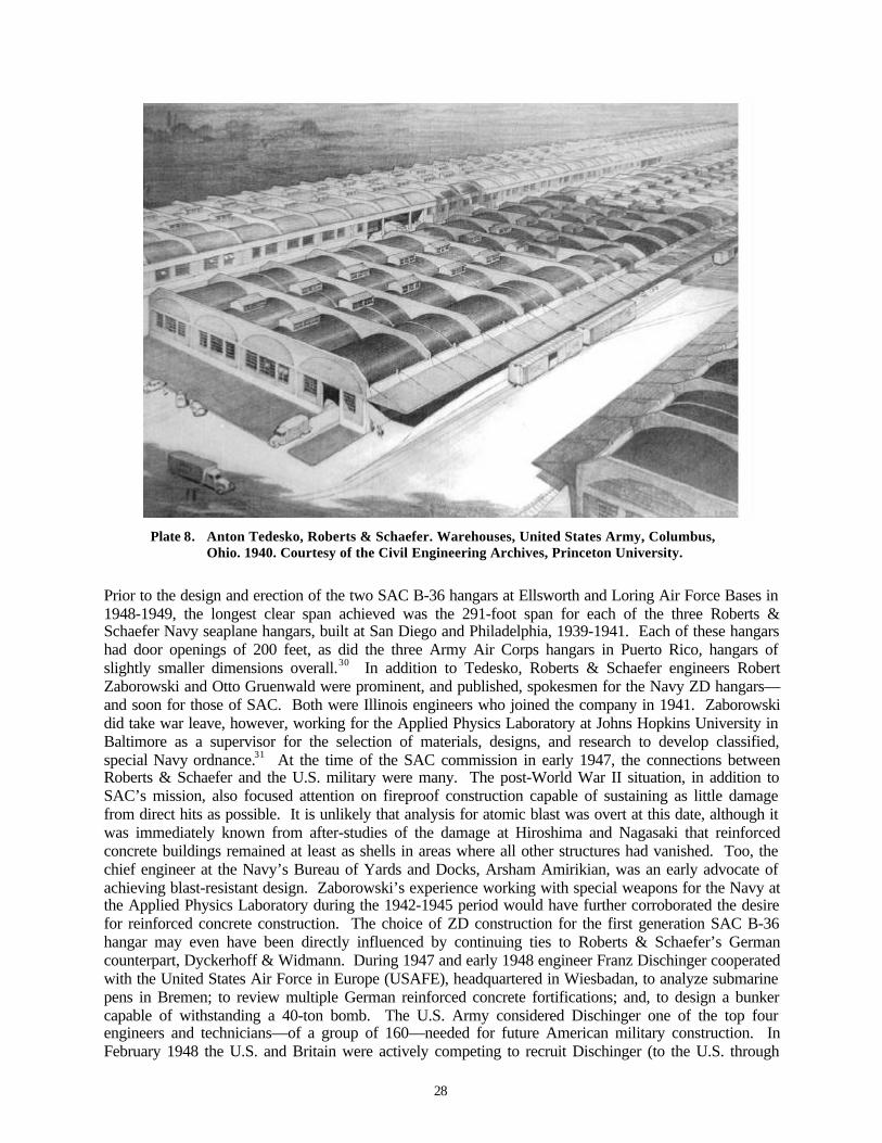
28
Plate 8. Anton Tedesko, Roberts & Schaefer. Warehouses, United States Army, Columbus,Ohio. 1940. Courtesy of the Civil Engineering Archives, Princeton University.
Prior to the design and erection of the two SAC B-36 hangars at Ellsworth and Loring Air Force Bases in1948-1949, the longest clear span achieved was the 291-foot span for each of the three Roberts &Schaefer Navy seaplane hangars, built at San Diego and Philadelphia, 1939-1941. Each of these hangarshad door openings of 200 feet, as did the three Army Air Corps hangars in Puerto Rico, hangars ofslightly smaller dimensions overall.30 In addition to Tedesko, Roberts & Schaefer engineers RobertZaborowski and Otto Gruenwald were prominent, and published, spokesmen for the Navy ZD hangars—and soon for those of SAC. Both were Illinois engineers who joined the company in 1941. Zaborowskidid take war leave, however, working for the Applied Physics Laboratory at Johns Hopkins University inBaltimore as a supervisor for the selection of materials, designs, and research to develop classified,special Navy ordnance.31 At the time of the SAC commission in early 1947, the connections betweenRoberts & Schaefer and the U.S. military were many. The post-World War II situation, in addition toSAC’s mission, also focused attention on fireproof construction capable of sustaining as little damagefrom direct hits as possible. It is unlikely that analysis for atomic blast was overt at this date, although itwas immediately known from after-studies of the damage at Hiroshima and Nagasaki that reinforcedconcrete buildings remained at least as shells in areas where all other structures had vanished. Too, thechief engineer at the Navy’s Bureau of Yards and Docks, Arsham Amirikian, was an early advocate ofachieving blast-resistant design. Zaborowski’s experience working with special weapons for the Navy atthe Applied Physics Laboratory during the 1942-1945 period would have further corroborated the desirefor reinforced concrete construction. The choice of ZD construction for the first generation SAC B-36hangar may even have been directly influenced by continuing ties to Roberts & Schaefer’s Germancounterpart, Dyckerhoff & Widmann. During 1947 and early 1948 engineer Franz Dischinger cooperatedwith the United States Air Force in Europe (USAFE), headquartered in Wiesbadan, to analyze submarinepens in Bremen; to review multiple German reinforced concrete fortifications; and, to design a bunkercapable of withstanding a 40-ton bomb. The U.S. Army considered Dischinger one of the top fourengineers and technicians—of a group of 160—needed for future American military construction. InFebruary 1948 the U.S. and Britain were actively competing to recruit Dischinger (to the U.S. through
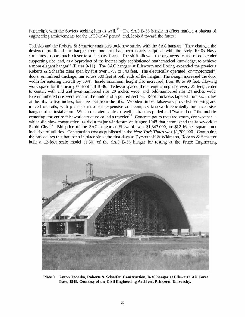
29
Paperclip), with the Soviets seeking him as well. 32 The SAC B-36 hangar in effect marked a plateau ofengineering achievements for the 1930-1947 period, and, looked toward the future.
Tedesko and the Roberts & Schaefer engineers took new strides with the SAC hangars. They changed thedesigned profile of the hangar from one that had been nearly elliptical with the early 1940s Navystructures to one much closer to a catenary form. The shift allowed the engineers to use more slendersupporting ribs, and, as a byproduct of the increasingly sophisticated mathematical knowledge, to achievea more elegant hangar33 (Plates 9-11). The SAC hangars at Ellsworth and Loring expanded the previousRoberts & Schaefer clear span by just over 17% to 340 feet. The electrically operated (or “motorized”)doors, on railroad trackage, ran across 300 feet at both ends of the hangar. The design increased the doorwidth for entering aircraft by 50%. Inside maximum height also increased, from 80 to 90 feet, allowingwork space for the nearly 60-foot tall B-36. Tedesko spaced the strengthening ribs every 25 feet, centerto center, with end and even-numbered ribs 20 inches wide, and, odd-numbered ribs 24 inches wide.Even-numbered ribs were each in the middle of a poured section. Roof thickness tapered from six inchesat the ribs to five inches, four feet out from the ribs. Wooden timber falsework provided centering andmoved on rails, with plans to reuse the expensive and complex falsework repeatedly for successivehangars at an installation. Winch-operated cables as well as tractors pulled and “walked out” the mobilecentering, the entire falsework structure called a traveler.34 Concrete pours required warm, dry weather—which did slow construction, as did a major windstorm of August 1948 that demolished the falsework atRapid City. 35 Bid price of the SAC hangar at Ellsworth was $1,343,000, or $12.16 per square footinclusive of utilities. Construction cost as published in the New York Times was $1,700,000. Continuingthe procedures that had been in place since the first days at Dyckerhoff & Widmann, Roberts & Schaeferbuilt a 12-foot scale model (1:30) of the SAC B-36 hangar for testing at the Fritze Engineering
Plate 9. Anton Tedesko, Roberts & Schaefer. Construction, B-36 hangar at Ellsworth Air ForceBase, 1948. Courtesy of the Civil Engineering Archives, Princeton University.
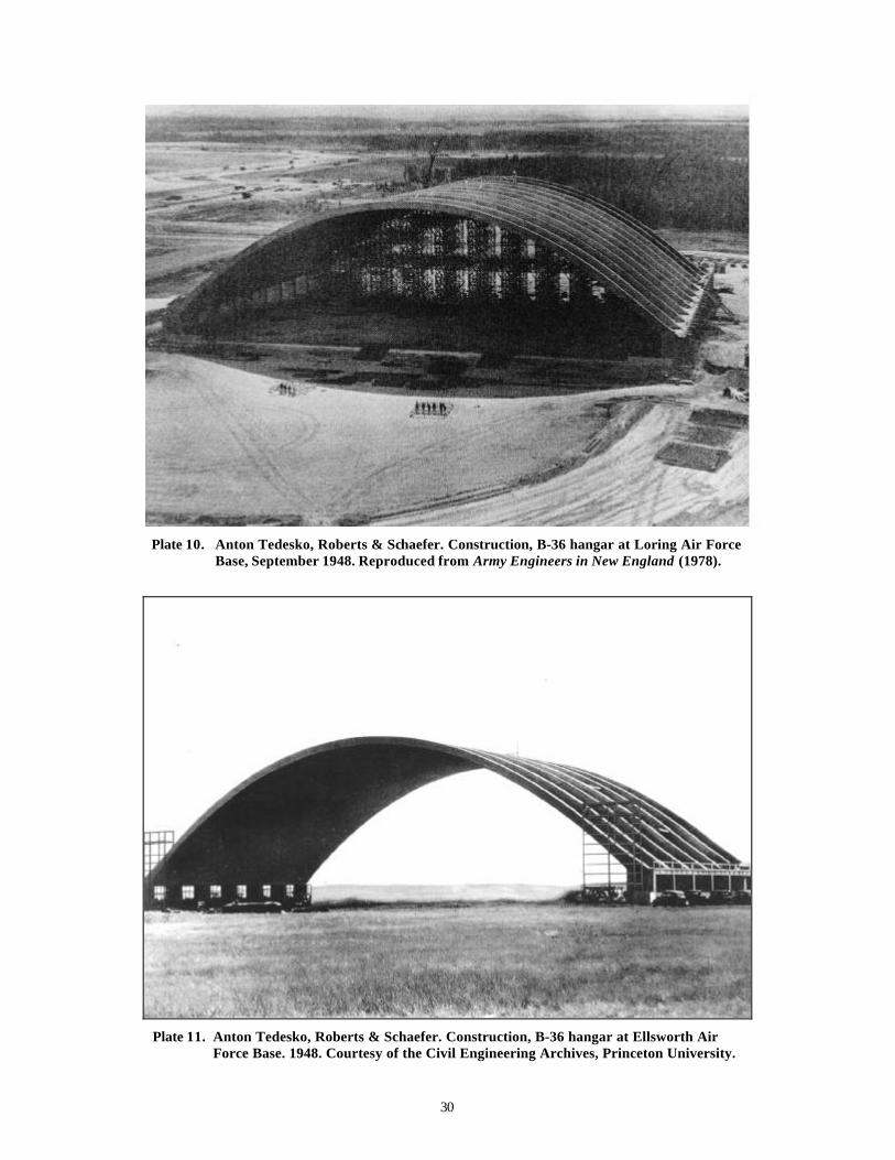
30
Plate 10. Anton Tedesko, Roberts & Schaefer. Construction, B-36 hangar at Loring Air ForceBase, September 1948. Reproduced from Army Engineers in New England (1978).
Plate 11. Anton Tedesko, Roberts & Schaefer. Construction, B-36 hangar at Ellsworth AirForce Base. 1948. Courtesy of the Civil Engineering Archives, Princeton University.

31
Laboratory at Lehigh University. Engineering journals heralded the two SAC hangars throughout 1948 to1953, including Civil Engineering, Engineering News-Record, Journal of the American ConcreteInstitute , and Airports and Air Carriers36 (Plate 12). Reinforced Concrete in Architecture, aninternational look at progressive design and engineering published in 1958, also featured the SAC B-36hangar.
Plate 12. B-36 hangar at Ellsworth Air Force Base. View of July 1999. Photograph, K.J.Weitze.
Thin-shell, reinforced concrete hangars of the early Cold War years also saw advancement for the firsttime at American civilian airfields. While the two first generation SAC B-36 hangars were in design,Ammann & Whitney—who became competitors of Roberts & Schaefer from the late 1940s forward—completed hangars for American Airlines and TWA at Midway Airport in Chicago (Plates 13-14). Bothhangars were double-span structures and were quite conservative. The American Airlines hangar featureda maximum clear span of 257 feet (1947), while the TWA hangar featured a clear span of 270 feet (1948),each smaller than the Navy seaplane hangar in San Diego of 1939-1941. Engineers Othmar Ammann andCharles S. Whitney, like the men at Roberts & Schaefer, were concerned about convincing potentialclients of the technology’s reasonable cost: for the American Airlines hangar, cost per square foot withutilities was $12.88.37 Engineers Gruenwald, Molke, and Zaborowski, of Roberts & Schaefer, publishedcost comparisons for the Ammann & Whitney American Airlines Chicago hangar against their SAChangar at Ellsworth—with the assumption by both firms that the four hangars in Chicago, South Dakota,and Maine would set the tone of hangar construction both in the U.S. military and at civilian airfieldsduring the 1950s.38 Swiss engineer Ammann (1879-1965) is best known for his bridge designs in urbanNew York.39
Although SAC did not choose to use the first generation B-36 hangar for its buildout worldwide,primarily due to construction delays and cement shortages, the hangar did see erection in two other guisesduring 1949-1952. Tedesko designed two hangars for the Ezeiza Airport in Buenos Aires (1949;$2,000,000); a hockey stadium for Quebec (1949: $3,000,000) and a municipal coliseum for Denver

32
(1951-1952: $2,250,000) (Plates 15-16). The Argentine hangars closely approximated the design, size,and span of the Ellsworth and Loring Air Force Base hangars of 1947-1949, although featured a clearspan of only 295 feet. The Quebec and Denver stadia were somewhat more conservative in clear span at240 and 254 feet, respectively. Not surprisingly, the stadia had a close competitor in a 1950 coliseumdesigned by Ammann & Whitney in Montgomery, Alabama, with 286-foot span. 40 Roberts & Schaeferdesigned a final group of seven thin-shell military hangars (each of 160-foot span: $1,750,000 per hangar)during 1951-1956 for the Navy Air Reserve Training (NART) program, with hangars erected in Denver(prototype); Guantanamo Bay, Cuba; Lincoln, Nebraska; Willow Grove, Pennsylvania; Niagara Falls,New York; Camp Lejeune, North Carolina; and Memphis, Tennessee41 (Plates 17-18).
Plate 13. Ammann & Whitney. American Airlines hangar, Midway Airport, Chicago. 1947.Reproduced from Reinforced Concrete in Architecture (1958). In use by ATA,September 1999.
Plate 14. Amman & Whitney. TWA hangar, Midway Airport, Chicago. 1948. Reproducedfrom American Building Art of the Twentieth Century (1961). In use by SouthwestAirlines, September 1999.
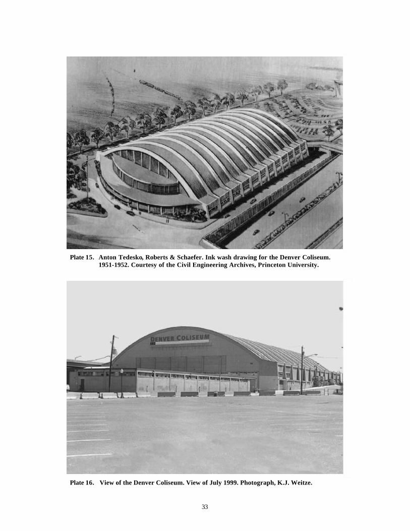
33
Plate 15. Anton Tedesko, Roberts & Schaefer. Ink wash drawing for the Denver Coliseum.1951-1952. Courtesy of the Civil Engineering Archives, Princeton University.
Plate 16. View of the Denver Coliseum. View of July 1999. Photograph, K.J. Weitze.

34
Plate 17. Anton Tedesko, Roberts & Schaefer. Prototype NART hangar, Buckley Field,Denver. 1951. Courtesy of the Civil Engineering Archives, Princeton University.
Plate 18. Anton Te desko, Roberts & Schaefer. NART hangar, Lincoln, Nebraska. View ofJuly 1999. [Today in use by the Nebraska ANG.] Photograph, K.J. Weitze.
35
At the close of the Navy hangar program, in 1956-1958, Roberts & Schaefer executed one final set ofarched reinforced concrete hangars for the Army Corps of Engineers. The Corps described these hangarsas “concrete” and “precast concrete,” with clear spans of 220 feet and length of 152 feet (Plates 19-20).Pull-through maintenance hangars, these do derive from the World War II – early Cold War thin-shellhangar, but appear to be an alternate design to an identically sized steel hangar built for joint ADC-SACuse after buildout of the second generation double-cantilever SAC bomber of 1951. The Air Forceintended these hangars to accommodate either fighters (such as the F-101B) or B-52 bombers.42 By themid-1950s the Air Force commissioned thin-shell barrel arches only rarely—but in at least two cases,with stunning results. At Larson Air Force Base in Moses Lake, Washington, Boeing built a $5.8 million-hangar to accommodate eight B-52s or KC-135 tankers, 1954-1957. Featuring a three-inch thick shell ofalternating low- and high-bay barrels, the hangar was 1,068 feet long and 372 feet wide, with clear spansof 217 feet. Seattle engineering firm Worthington & Skilling executed the design.43 In 1957-1958,Roberts & Schaefer again designed thin-shell construction for the Air Force at Olmsted Air Force Base inMiddletown, Pennsylvania, near Harrisburg. Two large warehouses featured ribless shells consisting of16 units, each measuring 200 by 200 feet.44 After 1955, Anton Tedesko went on to become a consultantto Air Force headquarters for the next 15-year period, focused on the engineering challenges for domed,reinforced concrete underground launch control centers for the intercontinental ballistic missile (ICBM)and on those for space vehicle launch platforms.45
Second Generation Maintenance Hangar for the B-36, B-47, and B-52
SAC selected the thin-shell, reinforced concrete hangar for the B-36 in early 1947, in all probability basedupon the known success of the construction technology for World War II Navy hangars; the behavior ofthe hangar, as-built for the AAF, through an intense fire at Wright-Patterson Air Force Base in 1945; and,the established relationship of Anton Tedesko with the U.S. military through the Roberts & Schaeferoffice in Washington, D.C. Secondarily, with an awareness that the Soviet Union would soon possess thecapability of reaching the American continent through a force of Tu-4s, SAC leadership may have alreadyhad some concerns about achieving the structural ability to survive at least traditional bombing withcontained damage. SAC, however, could not have predicted the level of post-World War II private sectordemands on the cement industry, with the ensuing shortages, nor could the command have comprehendedthe full impact of immediate post-World War II federal funding cutbacks. With the outbreak of theKorean conflict in mid-1950, a number of planning parameters changed. It was clear by this date thatactual erection of the thin-shell B-36 hangar was likely to be time-consuming, without ease of procuringconstruction materials.
At Loring in May 1948, SAC had anticipated 10 thin-shell hangars, built one after the other—anarrangement that would have accommodated 20 B-36s, two per maintenance hangar. (See Plate 4.) ByAugust 1950, the Loring construction program did not specify the projected number of hangars, butinstead recorded that 10 additional B-36s required hangars at an overall estimated facilities cost of fivemillion dollars.46 While what is immediately noticeable is the 50% reduction in number of bombers to bein maintenance at any one time, what is also pertinent is the lack of enumeration for the planned hangars.Not only had federal funding constrictions pulled in the anticipated infrastructure for the bombers, but theprogram was being rethought. The thin-shell hangar was not a flexible-use hangar for the B-36: it couldaccommodate two bombers, and only two bombers, in a nearly rigid manner. In 1950 aircraft werechanging, with a need to accommodate not just the B-36, but the B-47 (which entered SAC inventory inlate 1951) and in a few years the B-52 (in SAC inventory in mid-1955), with a probable mixed use atsome installations. In late 1950 SAC required an “expansible” heavy bomber hangar. With Korea, thecommand also needed hangars that could go up more like mobilization infrastructure.

36
Pla
te 1
9.
Ant
on T
edes
ko, R
ober
ts &
Sch
aefe
r. P
ull-
Thr
u H
anga
r, E
leva
tion
. 195
6-19
58. C
ourt
esy
of t
he H
isto
ry O
ffic
e, A
rmy
Cor
ps o
f E
ngin
eers
, F
ort
Bel
voir
, Vir
gini
a.
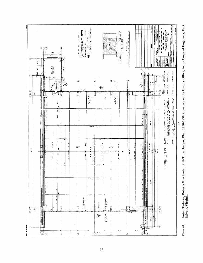
37
Pla
te 2
0.
Ant
on T
edes
ko, R
ober
ts &
Sch
aefe
r. P
ull-
Thr
u H
anga
r, P
lan.
195
6-19
58. C
ourt
esy
of t
he H
isto
ry O
ffic
e, A
rmy
Cor
ps o
f E
ngin
eers
, For
t B
elvo
ir, V
irgi
nia.
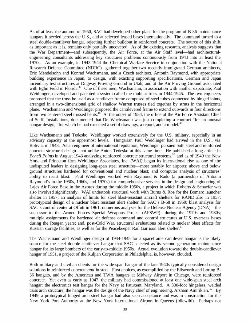
38
As of at least the autumn of 1950, SAC had developed other plans for the program of B-36 maintenancehangars it needed across the U.S., and at selected leased bases internationally. The command turned to asteel double-cantilever hangar, rejecting further buildout in reinforced concrete. The source of this shift,as important as it is, remains only partially uncovered. As of the existing research, analysis suggests thatthe War Department—and subsequently, the Air Force, at the Air Staff level—had architectural-engineering consultants addressing key structures problems continuously from 1943 into at least the1970s. As an example, in 1943-1944 the Chemical Warfare Service in conjunction with the NationalResearch Defense Committee (NDRC) gathered together two recently immigrated German architects,Eric Mendelsohn and Konrad Wachsmann, and a Czech architect, Antonin Raymond, with appropriatebuilding experience in Japan, to design, with exacting supporting specifications, German and Japanincendiary test structures at Dugway Proving Ground in Utah, and at the Air Proving Ground associatedwith Eglin Field in Florida.47 One of these men, Wachsmann, in association with another expatriate, PaulWeidlinger, developed and patented a system called the mobilar truss in 1944-1945. The two engineersproposed that the truss be used as a cantilever frame composed of steel tubes connected by hinged joints,arranged in a two-dimensional grid of shallow Warren trusses tied together by struts in the horizontalplane. Wachsmann and Weidlinger proposed the cantilevered frame to extend outwards in four directionsfrom two centered steel trussed bents.48 At the outset of 1954, the office of the Air Force Assistant Chiefof Staff, Installations, documented that Dr. Wachsmann was just completing a contract “for an unusualhangar design,” for which he had executed a set of drawings, a report, and a model.49
Like Wachsmann and Tedesko, Weidlinger worked extensively for the U.S. military, especially in anadvisory capacity at the uppermost levels. Hungarian Paul Weidlinger had arrived in the U.S., viaBolivia, in 1943. As an engineer of international reputation, Weidlinger pursued both steel and reinforcedconcrete structural design—not unlike Anton Tedesko at this same time. He published a long article inPencil Points in August 1943 analyzing reinforced concrete structural systems,50 and as of 1949 the NewYork and Princeton firm Weidlinger Associates, Inc. (WAI) began its international rise as one of theundisputed leaders in designing long-span steel structures—most notably for airports; above and belowground structures hardened for conventional and nuclear blast; and computer analysis of structures’ability to resist blast. Paul Weidlinger worked with Raymond & Rado (a partnership of AntoninRaymond’s in the 1950s, 1960s, and 1970s) for comprehensive services in the design and engineering ofLajes Air Force Base in the Azores during the middle 1950s, a project in which Roberts & Schaefer wasalso involved significantly. WAI undertook structural work with Burns & Roe for the Bomarc launchershelter in 1957; an analysis of limits for steel blast-resistant aircraft shelters for RAND also in 1957;prototypical design of a nuclear blast resistant alert shelter for SAC’s B-58 in 1959; blast analysis forSAC’s control center at Offutt in 1961; numerous analyses for the Defense Nuclear Agency (DNA)—thesuccessor to the Armed Forces Special Weapons Project (AFSWP)—during the 1970s and 1980s;multiple assignments for hardened air defense command and control structures at U.S. overseas basesduring the Reagan years; and, post-Cold War, structural evaluations related to nuclear blast effects forRussian storage facilities, as well as for the Peacekeeper Rail Garrison alert shelter.51
The Wachsmann and Weidlinger design of 1944-1945 for a spaceframe cantilever hangar is the likelysource for the steel double-cantilever hangar that SAC selected as its second generation maintenancehangar for its large bombers of the early-to-middle 1950s. Actual evolution toward the double-cantileverhangar of 1951, a project of the Kuljian Corporation in Philadelphia, is, however, clouded.
Both military and civilian clients for the wide-span hangar of the late 1940s typically considered designsolutions in reinforced concrete and in steel. First choices, as exemplified by the Ellsworth and Loring B-36 hangars, and by the American and TWA hangars at Midway Airport in Chicago, were reinforcedconcrete. Yet even as early as 1947, the military had commissioned at least one wide-span steel archhangar: the electronics test hangar for the Navy at Patuxent, Maryland. A 300-foot hingeless, weldedtruss arch structure, the hangar was the design of the Navy chief of engineering, Arsham Amirikian. 52 By1949, a prototypical hinged arch steel hangar had also seen acceptance and was in construction for theNew York Port Authority at the New York International Airport in Queens (Idlewild). Perhaps not
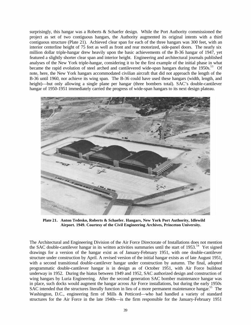
39
surprisingly, this hangar was a Roberts & Schaefer design. While the Port Authority commissioned theproject as set of two contiguous hangars, the Authority augmented its original intents with a thirdcontiguous structure (Plate 21). Achieved clear span for each of the three hangars was 300 feet, with aninterior centerline height of 75 feet as well as front and rear motorized, side-panel doors. The nearly sixmillion dollar triple-hangar drew heavily upon the basic achievements of the B-36 hangar of 1947, yetfeatured a slightly shorter clear span and interior height. Engineering and architectural journals publishedanalyses of the New York triple-hangar, considering it to be the first example of the initial phase in whatbecame the rapid evolution of steel arched and cantilevered wide-span hangars during the 1950s.53 Ofnote, here, the New York hangars accommodated civilian aircraft that did not approach the length of theB-36 until 1960, nor achieve its wing span. The B-36 could have used these hangars (width, length, andheight)—but only allowing a single plane per hangar (three bombers total). SAC’s double-cantileverhangar of 1950-1951 immediately carried the progress of wide-span hangars to its next design plateau.
Plate 21. Anton Tedesko, Roberts & Schaefer. Hangars, New York Port Authority, IdlewildAirport. 1949. Courtesy of the Civil Engineering Archives, Princeton University.
The Architectural and Engineering Division of the Air Force Directorate of Installations does not mentionthe SAC double-cantilever hangar in its written activities summaries until the start of 1953.54 Yet signeddrawings for a version of the hangar exist as of January-February 1951, with one double-cantileverstructure under construction by April. A revised version of the initial hangar exists as of late August 1951,with a second transitional double-cantilever hangar under construction by autumn. The final, adoptedprogrammatic double-cantilever hangar is in design as of October 1951, with Air Force buildoutunderway in 1952. During the hiatus between 1949 and 1952, SAC authorized design and construction ofwing hangars by Luria Engineering. After the second generation SAC bomber maintenance hangar wasin place, such docks would augment the hangar across Air Force installations, but during the early 1950sSAC intended that the structures literally function in lieu of a more permanent maintenance hangar.55 TheWashington, D.C., engineering firm of Mills & Petticord—who had handled a variety of standardstructures for the Air Force in the late 1940s—is the firm responsible for the January-February 1951
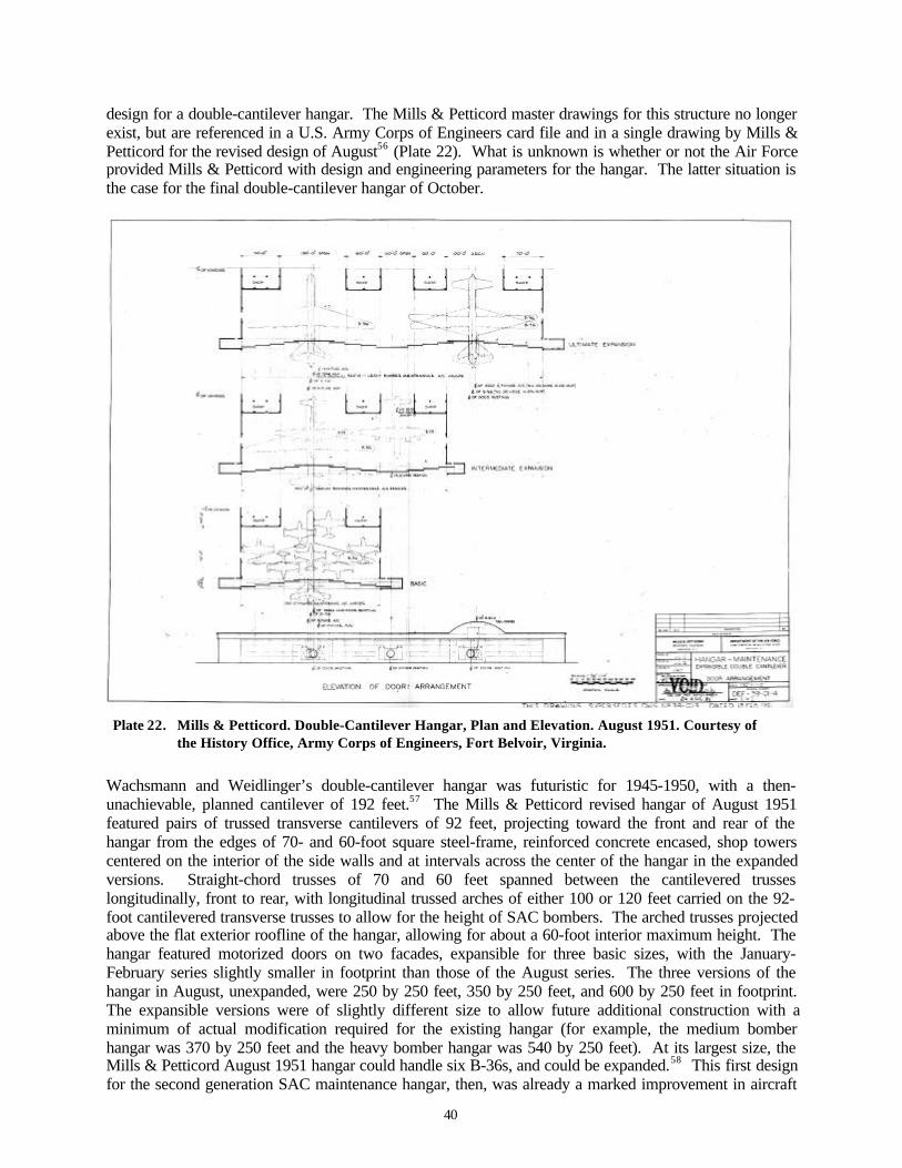
40
design for a double-cantilever hangar. The Mills & Petticord master drawings for this structure no longerexist, but are referenced in a U.S. Army Corps of Engineers card file and in a single drawing by Mills &Petticord for the revised design of August56 (Plate 22). What is unknown is whether or not the Air Forceprovided Mills & Petticord with design and engineering parameters for the hangar. The latter situation isthe case for the final double-cantilever hangar of October.
Plate 22. Mills & Petticord. Double-Cantilever Hangar, Plan and Elevation. August 1951. Courtesy ofthe History Office, Army Corps of Engineers, Fort Belvoir, Virginia.
Wachsmann and Weidlinger’s double-cantilever hangar was futuristic for 1945-1950, with a then-unachievable, planned cantilever of 192 feet.57 The Mills & Petticord revised hangar of August 1951featured pairs of trussed transverse cantilevers of 92 feet, projecting toward the front and rear of thehangar from the edges of 70- and 60-foot square steel-frame, reinforced concrete encased, shop towerscentered on the interior of the side walls and at intervals across the center of the hangar in the expandedversions. Straight-chord trusses of 70 and 60 feet spanned between the cantilevered trusseslongitudinally, front to rear, with longitudinal trussed arches of either 100 or 120 feet carried on the 92-foot cantilevered transverse trusses to allow for the height of SAC bombers. The arched trusses projectedabove the flat exterior roofline of the hangar, allowing for about a 60-foot interior maximum height. Thehangar featured motorized doors on two facades, expansible for three basic sizes, with the January-February series slightly smaller in footprint than those of the August series. The three versions of thehangar in August, unexpanded, were 250 by 250 feet, 350 by 250 feet, and 600 by 250 feet in footprint.The expansible versions were of slightly different size to allow future additional construction with aminimum of actual modification required for the existing hangar (for example, the medium bomberhangar was 370 by 250 feet and the heavy bomber hangar was 540 by 250 feet). At its largest size, theMills & Petticord August 1951 hangar could handle six B-36s, and could be expanded.58 This first designfor the second generation SAC maintenance hangar, then, was already a marked improvement in aircraft

41
capacity over the Roberts & Schaefer thin-shell hangar of 1947. It also planned for a more flexible useand allowed for changing aircraft dimensions.
The original Mills & Petticord SAC maintenance hangar of January-February 1951—for which no signedMills & Petticord master drawings are extant—is annotated by dimension for each of the basic, mediumbomber (B-47), and heavy bomber (B-36) versions in the Corps card file for superceded definitivedrawings. The dimensions of the Mills & Petticord expansible medium bomber hangar of early 1951 arematched in a double-cantilever hangar under construction at Kirtland Air Force Base in late April 1951.The existing drawings at Kirtland are signed by the responsible site contractor for the hangar, Pacific Ironand Steel of Los Angeles. Both the existing hangar itself, and the April 1951 plans, sections, andelevations, indicate that Mills & Petticord’s original double-cantilever design approached the cantileveridea with more conservatism than in their final version of August. The Kirtland SAC hangar is a double-cantilever design, employing paired transverse trussed bents, with longitudinal straight-chord trusses andtrussed arches. The three interior shop towers are 60 by 100 feet, supporting transverse cantilevers ofonly 66.5 feet. One side of the hangar is further enclosed for lean-to shops. The Kirtland double-cantilever hangar, built for the B-47, is the first known example of the SAC steel double-cantilever hangaranywhere, and may be unique 59 (Plates 23-24).
As of late April also, however, SAC authorized a second double-cantilever hangar for one of its basesbeginning construction in French Morocco: Nouasseur. The Nouasseur hangar is documented by itsfootprint on maps of late 1951 as either a B-36 hangar (580 by 244 feet) or an expansible B-36 hangar(560 by 244 feet), and had foundations under construction by late autumn. The Air Force inspectionreport of December describes this structure as “the Pacific Iron and Steel Company Hangar Building,”indicating that it was likely at least planned from one of the Mills & Petticord designs.60 The NouasseurSAC hangar in fact may be either the Mills & Petticord hangar of January-February 1951, the firm’shangar of August 1951, or, one of the first built from the final Kuljian Corporation designs for the SACbomber maintenance hangar—if SAC delayed construction past the foundations until early in 1952. Thefirst six B-36s arrived at Sidi Slimane, another SAC base built in French Morocco, in early December1951, completing their 5,000-mile training flight from Carswell Air Force Base in Fort Worth, Texas. Ofnote, both Kirtland and Nouasseur had atomic bomb storage sites, Q Areas, at their installations (Plates25-26).
Just as SAC had chosen not to follow through with the Roberts & Schaefer thin-shell maintenance hangarfor the B-36 designed by Tedesko, the command aborted the program for the Mills & Petticord steeldouble-cantilever bomber maintenance hangar of 1951. In September 1951, immediately after Mills &Petticord submitted its August revisions for the double-cantilever hangar, the Army Corps of Engineerscontacted Kuljian Corporation in Philadelphia—requesting that the firm design a double-cantileverhangar for SAC. Circumstances for the change from Mills & Petticord to Kuljian, like the partiallyverified but still illusive reference to Konrad Wachsmann, are not fully conclusive. As remembered byArthur Kuljian in 1999, Kuljian engineering had sent one of their partners, Bob Lundgren, to the Corps ofEngineers office in Washington, D.C., to introduce the Philadelphia firm to the Corps and to indicate thatKuljian was interested in being considered for military work. The call on the Corps was of the courtesytype, not anticipated to lead to any immediate opportunities. On Friday of this same week, the Corpstelephoned Kuljian’s office in Philadelphia, and asked to meet with a Kuljian team the following Mondayin Washington, D.C. Another Kuljian partner, Jim Cherry, cut his weekend short at the New Jersey shoreto join Bob Lundgren in Washington. The contract was signed that same day. As the Corps explained toKuljian, the construction agency had called off negotiations with another firm and needed an immediateresponse to the engineering task at hand. All of this was unusual: as Arthur Kuljian noted, there had notbeen a competition for the double-cantilever bomber hangar, and, as they had been contacted from whatwas essentially a cold marketing call, the Corps did not have a list of engineering firms for the job fromwhich it could turn to the next candidate.61
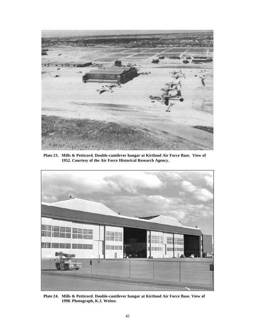
42
Plate 23. Mills & Petticord. Double-cantilever hangar at Kirtland Air Force Base. View of1952. Courtesy of the Air Force Historical Research Agency.
Plate 24. Mills & Petticord. Double-cantilever hangar at Kirtland Air Force Base. View of1998. Photograph, K.J. Weitze.

43
Pla
te 2
5.
Cen
ter
grou
ping
of
thre
e do
uble
-can
tile
ver
hang
ars.
Tw
o K
ulji
an h
anga
rs b
rack
et t
he M
Ills
& P
etti
cord
han
gar
of e
arly
195
1.
Kir
tlan
d A
ir F
orce
Bas
e. D
irec
tora
te o
f In
stal
lati
ons.
Mas
ter
Pla
n of
Oct
ober
195
7. C
olle
ctio
n of
K.J
. Wei
tze.
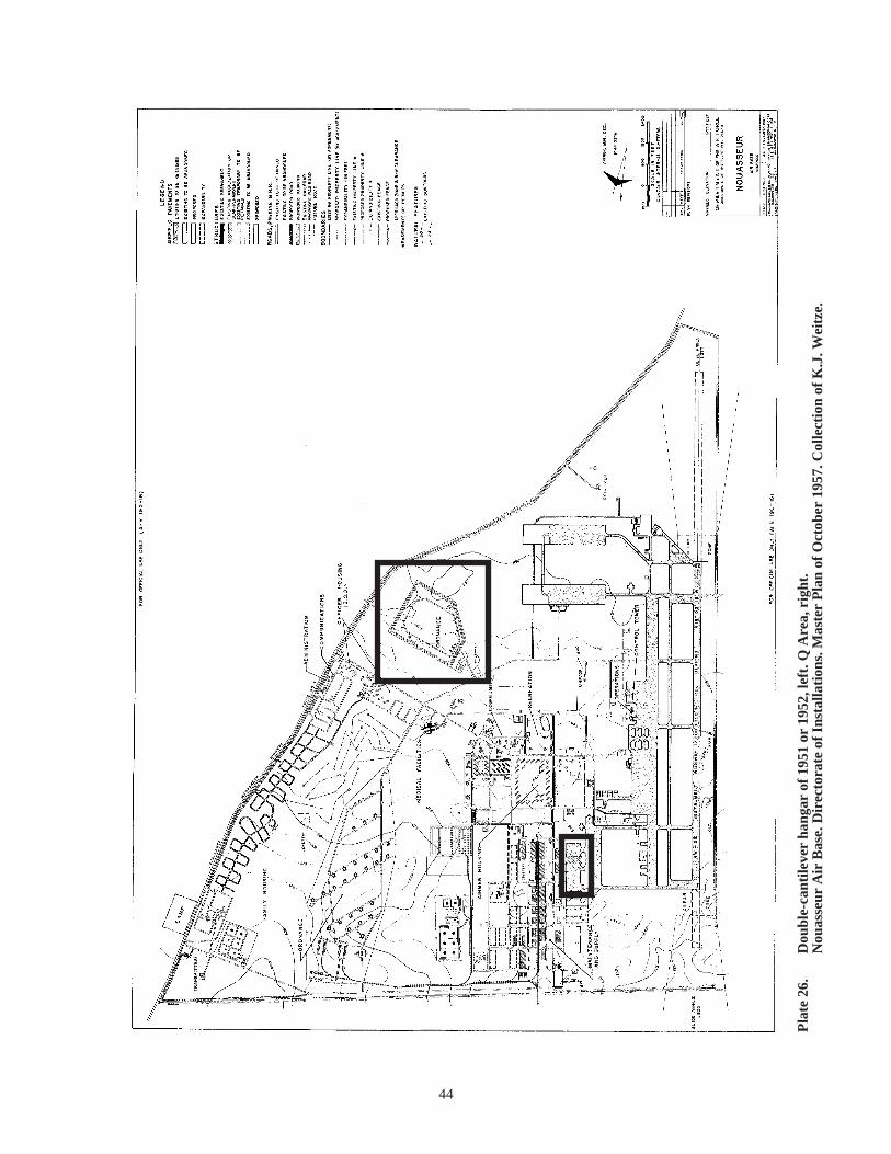
44
Pla
te 2
6.
Dou
ble-
cant
ileve
r ha
ngar
of
1951
or
1952
, lef
t. Q
Are
a, r
ight
.N
ouas
seur
Air
Bas
e. D
irec
tora
te o
f In
stal
lati
ons.
Mas
ter
Pla
n of
Oct
ober
195
7. C
olle
ctio
n of
K.J
. Wei
tze.

45
The Corps (in essence for SAC) requested the programmatic hangar explicitly: it was to be a steel double-cantilever hangar; it was to come in three sizes and have expansible versions. The SAC bomber hangar, inits five versions, was annotated as HB (heavy bomber for the B-36), MB (medium bomber for the B-47),X-1 (basic version, expansible), X-2 (intermediate—medium bomber—expansible), and X-3 (ultimate—heavy bomber—expansible). Kuljian was to design a hangar for different temperature zones; forearthquake conditions; with three alternate roof loading specifications (for 20, 30, and 40 pounds persquare foot), and exterior sheathing in cement asbestos fluted paneling (“protected metal siding”); andaccommodating heating systems for coal, oil, or gas. The Corps specified that the cantilever system wasto spring from interior shop towers (also referred to as “columns” in published engineering articles). Assubmitted the Kuljian designs had footprint dimensions matching those of the August 1951 Mills &Petticord designs precisely, and had interior cantilevered transverse trusses. The straight-chord trussesand the arched trusses were also all of nearly an exact match—strongly suggesting that these items, too,were in the specifications provided to Kuljian by the Corps.62 Kuljian issued its first drawings for theSAC hangar on 28 September 1951, almost exactly a month from the date of the second Mills & Petticordsubmittal and the cutoff of the Mills & Petticord contract. Arthur Kuljian’s handwritten note in the firm’sbook of project schedules for drawings noted: “Drawings, designs, specs all done in record time of 15weeks.” Kuljian completed its issuance of the initial drawings series—more than 200 drawings—on 7December 1951.63 As the project moved forward each of the five hangars in the double-cantilever serieswould require 60 to 65 individual drawings64 (Plates 27-28).
Dr. Harry A. Kuljian, Arthur Kuljian’s father, had founded Kuljian Corporation in 1930 as an engineeringfirm primarily handling industrial and power generation projects. Dr. Kuljian had immigrated to the U.S.from Turkey as a teenager just before World War I, after working there in a textile factory since age eight.Continuing work in the U.S., and attending high school at night, Dr. Kuljian entered the MassachusettsInstitute of Technology (MIT). Subsequently he worked as an engineer for two power companies andfinally American Viscose, a company manufacturing rayon. When Dr. Kuljian went into business forhimself, he leveraged his expertise in power plant and textile industry engineering to design captivepower generation for eight rayon production sites in the U.S. and Canada. During World War II, theNavy hired Kuljian Corporation to design power plants at multiple Naval yards on the East Coast and inSubic Bay, in the Philippines. The firm undertook some work in regional transportation engineering as of1949-1950, inclusive of engineering for the expansion of the Philadelphia airport. Handled by Kuljian’schief engineer, Walter Fasshauer, the SAC double-cantilever assignment of 1951 was the firm’s first workfor the Air Force. Of German descent, Fasshauer had been with Kuljian since 1934. Kuljian Corporationhandled a significant amount of international work, particularly in the Middle and Far East, from its earlyyears forward. By 1958, the firm expanded to fully 75 percent of its work overseas, with large foreigngovernment projects in India, Pakistan, Iran, Iraq, and Korea, and inclusive of a 10,000-foot runway forthe airport in Kurachi, Pakistan during 1958-1960. 65
The Kuljians were active members of the Armenian community, and as such Dr. Kuljian knew ArshamAmirikian (1899-1990), the brilliant, highly innovative Armenian engineer who served as the chief ofengineering for the Navy’s Bureau of Yards and Docks. Amirikian had arrived in the U.S. just afterWorld War I, and after a degree from Cornell worked as a structural draftsman for a series of steelfabrication shops. His career with the Navy ran from the late 1920s into the early 1970s. An interestingcoincidence, perhaps, both Arsham Amirikian and Anton Tedesko matriculated with their doctorates latein their lives at the Institute of Technology in Vienna—while they continued their professions in the U.S.Dr. Amirikian also retired in the Air Force Reserves. Among his most noteworthy engineeringaccomplishments had been the design of the Navy’s wood dirigible hangar of World War II (for whichTedesko had designed a steel prototype for the Naval Air Station in Lakehurst, New Jersey); the design ofspecial structures; and the early analysis of engineering for nuclear blast.66 And, immediately prior to thefirst designs for the double-cantilever hangar, Amirikian had engineered the Navy’s 300-foot steel archhangar at Patuxent. With the active role of the engineering division of the Navy Yards and Docks in the
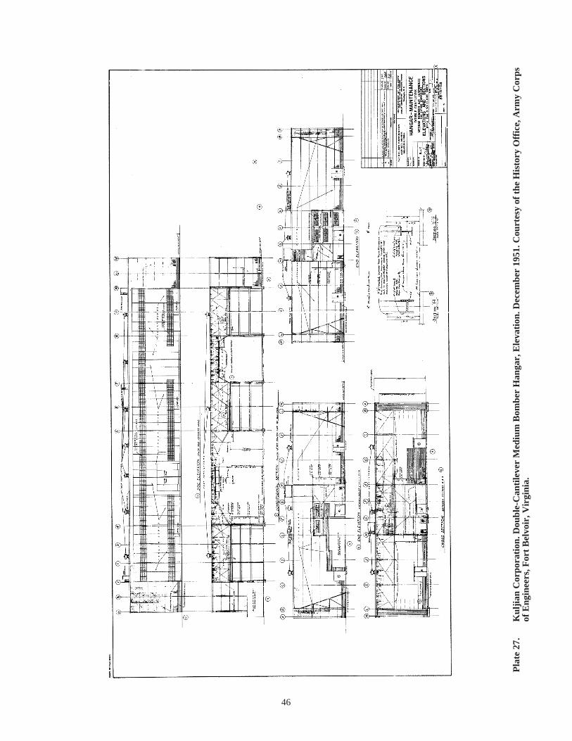
46
Pla
te 2
7.
Kul
jian
Cor
pora
tion
. Dou
ble-
Can
tile
ver
Med
ium
Bom
ber
Han
gar,
Ele
vati
on. D
ecem
ber
1951
. Cou
rtes
y of
the
His
tory
Off
ice,
Arm
y C
orps
of
Eng
inee
rs, F
ort
Bel
voir
, Vir
gini
a.
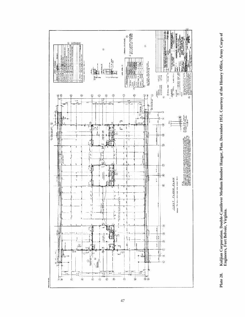
47
Pla
te 2
8.
Kul
jian
Cor
pora
tion
. Dou
ble-
Can
tile
ver
Med
ium
Bom
ber
Han
gar,
Pla
n. D
ecem
ber
1951
. Cou
rtes
y of
the
His
tory
Off
ice,
Arm
y C
orps
of
Eng
inee
rs, F
ort
Bel
voir
, Vir
gini
a.

48
construction efforts of the Air Force in the late 1940s and early 1950s, and with the first B-36 thin-shellhangars at Ellsworth and Loring strongly linked to Navy precedents, it is probable that Amirikian mayhave played a role in the Corps’ call to Kuljian.
SAC built approximately 50 to 60 of its second generation bomber maintenance hangars at approximately46 Air Force installations in the U.S. and internationally between 1952 and 195567 (Plates 29-38). (SeeTable 2, chapter 3.) The hangar effectively came in three sizes, with the intermediate and largeststructures also possible in an expansible version. The smallest hangar could accommodate two B-36s,and was sometimes referred to as a single-bay, eight-panel structure. The intermediate hangar couldaccommodate four B-36s, and was alternately designated a two-bay, 11-panel structure. The largesthangar could accommodate six B-36s, referenced as a three-bay, 16-panel structure. “Bays” wereconfigured based on the interior trussed archways, while “panels” referred to the number of motorizeddoor panels running on railroad track across the front and rear facades. Although the hangar presented theappearance of a pull-through structure, it was intended to be entered from each side by three bombers,with either aircraft noses or tails left projecting through canvas-sheathed openings in the appropriatepanels.
Plate 29. Kuljian Corporation. Heavy bomber (three-bay) double-cantilever hangar at the former LoringAir Force Base. View of 1995. Courtesy of Mariah Associates, Inc.

49
Plate 30. Kuljian Corporation. Heavy bomber (three-bay) double-cantilever hangar atCarswell Air Force Base. View of the middle 1950s. Courtesy of the KuljianCorporation.
Plate 31. Kuljian Corporation. Paired, medium bomber (two-bay) double-cantilever hangarsat Goose Bay Air Base. View of the middle 1950s. Courtesy of the KuljianCorporation.
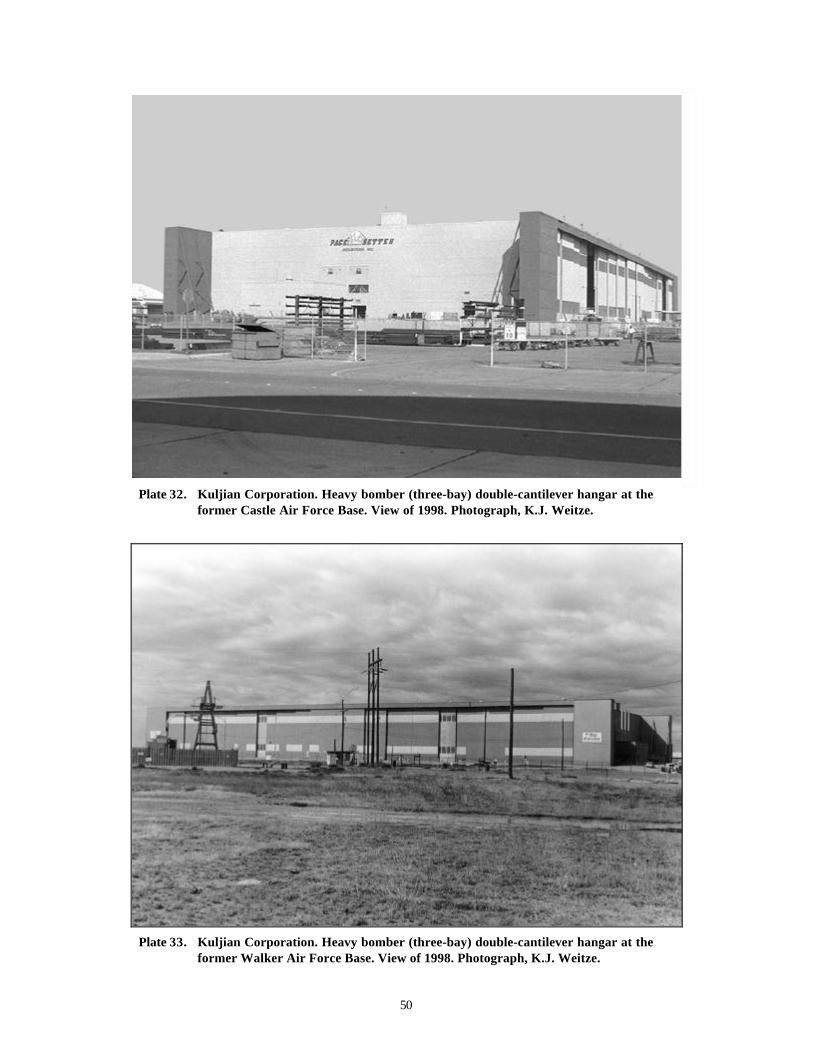
50
Plate 32. Kuljian Corporation. Heavy bomber (three-bay) double-cantilever hangar at theformer Castle Air Force Base. View of 1998. Photograph, K.J. Weitze.
Plate 33. Kuljian Corporation. Heavy bomber (three-bay) double-cantilever hangar at theformer Walker Air Force Base. View of 1998. Photograph, K.J. Weitze.

51
Plate 34. Kuljian Corporation. Medium bomber (two-bay) double-cantilever hangar at theformer Schilling Air Force Base. View of 1999. Photograph, K.J. Weitze.
Plate 35. Kuljian Corporation. Medium bomber (two-bay) double-cantilever hangar at theformer Lincoln Air Force Base. View of 1999. Photograph, K.J. Weitze.
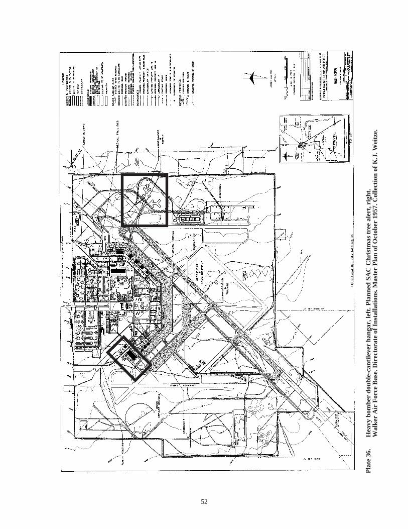
52
Pla
te 3
6.
Hea
vy b
ombe
r do
uble
-can
tile
ver
hang
ar, l
eft.
Pla
nned
SA
C C
hris
tmas
tre
e al
ert,
rig
ht.
Wal
ker
Air
For
ce B
ase.
Dir
ecto
rate
of
Inst
alla
tion
s. M
aste
r P
lan
of O
ctob
er 1
957.
Col
lect
ion
of K
.J. W
eitz
e.
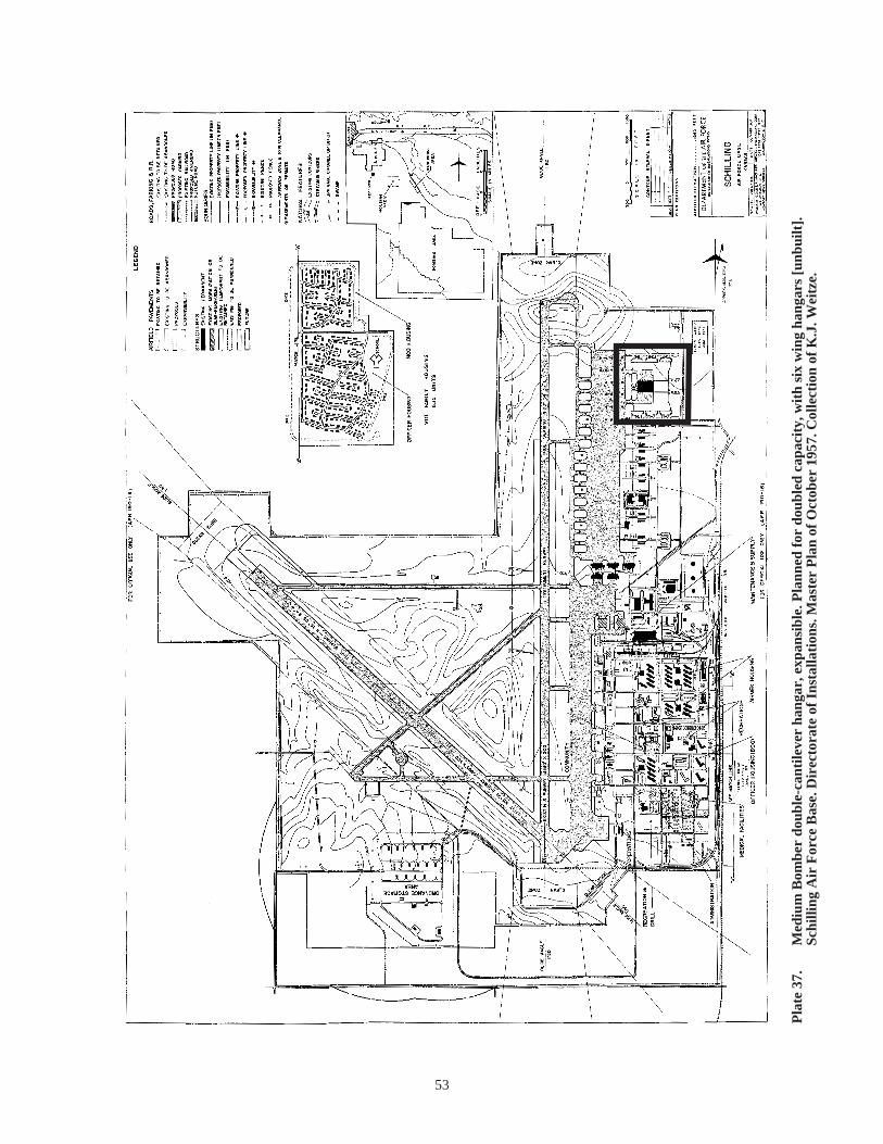
53
Pla
te 3
7.
Med
ium
Bom
ber
doub
le-c
anti
leve
r ha
ngar
, exp
ansi
ble.
Pla
nned
for
dou
bled
cap
acit
y, w
ith
six
win
g ha
ngar
s [u
nbui
lt].
Sc
hilli
ng A
ir F
orce
Bas
e. D
irec
tora
te o
f In
stal
lati
ons.
Mas
ter
Pla
n of
Oct
ober
195
7. C
olle
ctio
n of
K.J
. Wei
tze.

54
Pla
te 3
8.
Pai
red
med
ium
bom
ber
doub
le-c
anti
leve
rs h
anga
rs. M
ulti
-pur
pose
win
g ha
ngar
s, le
ft. B
- w
ing
hang
ars,
cen
ter,
pla
nned
for
rem
oval
. G
roup
ing
of 1
0 m
ulti
-pur
pose
win
g ha
ngar
s, p
lann
ed, c
ente
r an
d ri
ght
[unb
uilt
]. L
inco
ln A
ir F
orce
Bas
e. D
irec
tora
te o
f In
stal
lati
ons.
M
aste
r P
lan
of O
ctob
er 1
957.
Col
lect
ion
of K
.J. W
eitz
e.

55
The key achievement of the structure was its very wide, unobstructed clear span and its flexibility: the AirForce could adapt the very large hangar, in any of its five versions, to multiple aircraft over time; and,should the Air Force choose, it could expand the hangar with relative ease. Kuljian redesigned the towersto be a uniform 60 feet square throughout the hangar (rather than 70 feet square for the towers along thesides of the structure and 60 feet square in the center). The firm also thereby extended the trussedcantilevers from the 92 feet of Mills & Petticord’s final August 1951 version, to 93.6 feet center to rear,and to 104 feet center to front. The hangar, in its steel-frame construction, recalled mobilizationinfrastructure through its standardized, shippable components, all of which could be handled by non-specialized labor. Steel fabrication and bridge companies could manufacture the truss segments.Corrugated insulated exterior paneling, typically left unpainted during the early Cold War decades (andsometimes still found in this state), resembled that of prefabricated metal buildings. Cost for the Kuljianhangars was approximately three-and-one-half to four-and-one-half million dollars. The hangar coveredtwo to three-and-one-half acres of ground68 (Plates 39-42).
Of the buildout for the second generation SAC bomber maintenance hangar, most hangars were of thesingle-bay type, with the triple-bay structure relatively rare. It is unknown whether SAC actually everexpanded a double-cantilever hangar once erected, but as of its master planning in late 1957, the intentwas to do so at over 20 installations. Triple-bay hangars in the U.S. included ones for Biggs (Texas),Carswell (Texas), Castle (California), Loring (Maine), McGuire (New Jersey), Pease (New Hampshire),Plattsburgh (New York), and Walker (New Mexico);69 with additional triple-bay hangars known to havebeen built for Lajes (Azores), Nouasseur (French Morocco), and Keflavik (Iceland). Tonnage ofstructural steel, for example, in the hangar at Castle totaled 3,262, fabricated by the Union Steel Companyof Los Angeles. Each trussed cantilever itself weighted 35 tons, with door panels weighing 18 to 22 tonseach. Door panels measure 30 to 35 feet wide, by 60 feet tall.70 Contractors shipped the doors in 12 by60-foot sections, then assembling the final panels at the installation. For the hangars at Keflavik andLajes, the construction team finished one hangar, and after a brief vacation back in the U.S., flew to thenext location—facing entirely different local conditions.71 The double-cantilever hangar is the equivalentof a building six-and-one-half stories in height. Kuljian handled the definitive design for the SACdouble-cantilever hangar (December 1951), as well as a major revised drawings series in 1952, and siteadaptations for most of the individual installations.72 Occasionally, as at Keflavik and Lajes, distinctivesite adaptations were made. In 1954, Kuljian revised the drawings again, to eliminate the expansiblefeature.73
Early in the buildout, Kuljian also performed an “alternate design review” for four hangars—those atBiggs, Castle, Kirtland, and Walker Air Force Bases. These alternate designs pre-existed Kuljian in atleast some capacity. That at Kirtland is the January-February 1951 double-cantilever hangar designed byMills & Petticord. (See Plates 23-24.) Those at the other three installations are each triple-bay hangars,erected very early, and at least in the cases of Castle and Walker, appear to be standard Kuljian hangarsfrom their exterior. (The trussed arches do not protrude from the roofline.) The Biggs hangar is as yetunseen for interpretation here. If these three hangars are not Kuljian designs, then they too are likelyregional Corps of Engineers adaptations from one of the Mills & Petticord aborted designs. If so, theinterior tower shops will have a larger footprint and the cantilevered trusses will measure 66.5 or 92 feet,instead of 93.5 and 104 feet; and, shop tower plan dimensions will measure 60 by 100 feet, or 70 feet and60 feet square. As-built, the overall height of the hangar should have been about five stories instead ofsix-and-one-half. Of note, the records of the 93rd bombardment wing at Castle describe that installation’sdouble-cantilever hangar as having 70-foot square shop towers, and of five stories height—suggesting anadaptation from the August 1951 Mills & Petticord design, with a more conservative cantilever of 92feet.74 Supporting the possibility that the Biggs, Castle, and Walker hangars are derived from the August1951 Mills & Petticord version of the double-cantilever hangar are annotations on the Corps card indexfor the drawings: although Mills & Petticord made only two sheets of drawings for this version of thehangar, penciled is a date of 10 October 1952—strongly suggesting that SAC used these drawings forseveral of its earliest double-cantilever hangars, even as the Kuljian program was beginning buildout.75 Inthree instances, bases chose to add unauthorized basements under the shops within the double-cantilever
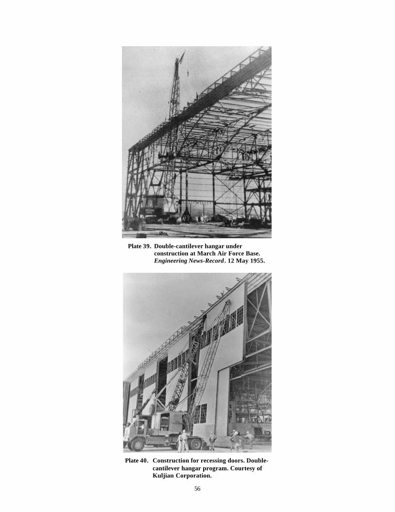
56
Plate 39. Double-cantilever hangar underconstruction at March Air Force Base.Engineering News-Record . 12 May 1955.
Plate 40. Construction for recessing doors. Double-cantilever hangar program. Courtesy ofKuljian Corporation.
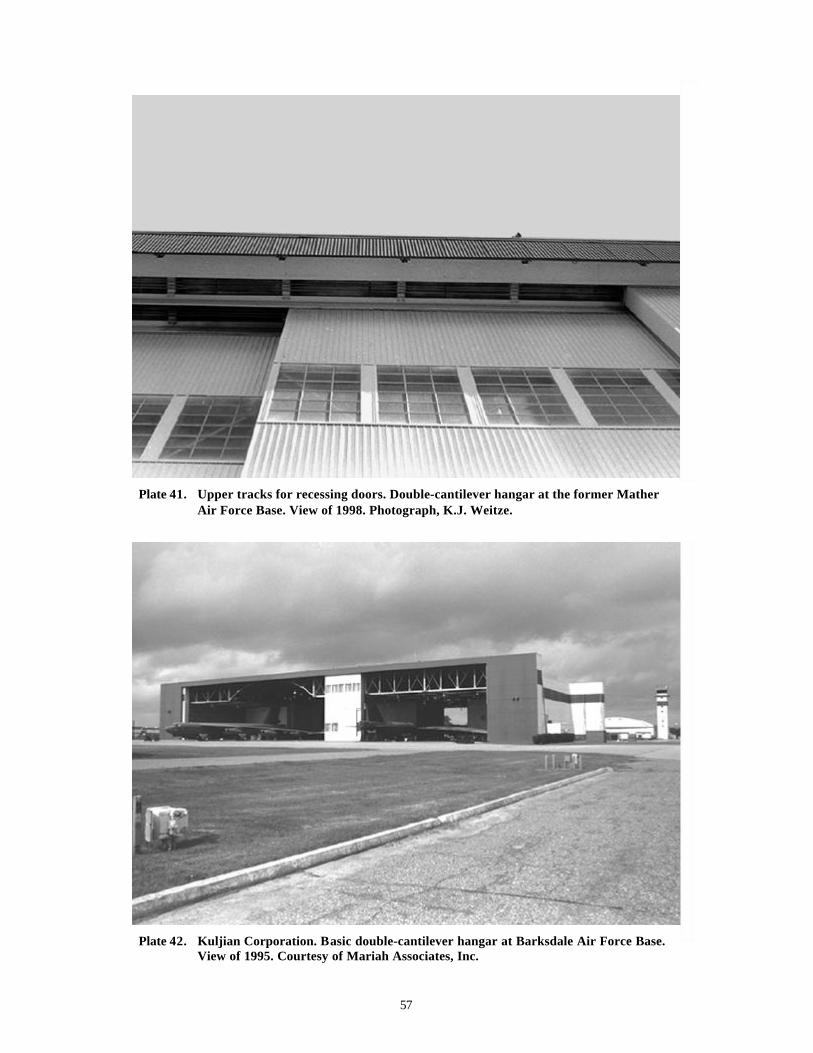
57
Plate 41. Upper tracks for recessing doors. Double-cantilever hangar at the former MatherAir Force Base. View of 1998. Photograph, K.J. Weitze.
Plate 42. Kuljian Corporation. Basic double-cantilever hangar at Barksdale Air Force Base.View of 1995. Courtesy of Mariah Associates, Inc.

58
hangar—at Biggs, Pinecastle, and Charleston. Headquarters Air Force ordered these sealed off in early1955. 76
Although the Air Force was beginning to address the needs of nuclear blast-resistant construction duringthe 1950s—particularly fringe area, non-direct hit construction, the first and second generation SACbomber maintenance hangars could only be interpreted as coincidentally touching upon these issues. Thethin-shell, reinforced concrete hangar of 1947 was an arch structure, and as such the arch and the domebest withstand the large lateral and vertical loads of airblast waves when a structure of more than 150 feet,like the SAC bomber hangar, is required.77 Reinforced concrete also offers some shield from radiation.Wide-span steel-frame structures do not offer much, if any blast or radiation protection, withoutreinforced concrete shear walls. Nominally though, the rectangular shape of the unexpanded double-cantilever hangar (in any of its five versions) of 1951; its length to width ratios (as taken from either thefront/rear facades or from the sides)—not in excess of the one to three ratio known to be a benchmark bythe middle 1950s; its interior tower shops heavily encased in reinforced concrete (serving as partial shearwalls); and, its deeply corrugated exterior metal paneling—fit the profile for simple blast effective designparameters. Personnel, too, would have been minimally protected within the tower shops fromradiation. 78 The SAC bomber hangars of 1947 and 1951, nonetheless, were not explicitly designed toresist the loads quantified for nuclear blast during the early 1950s.79
The greatest number of double-cantilever hangars were clustered in the interior U.S., across the Midwestbetween Nebraska and Louisiana, with both coasts also supplying bases for the bomber. At selectedinstallations, SAC built two separate double-cantilever hangars, achieving the capacity of the triple-bayhangar. The hangar programs for Ernest Harmon (Newfoundland) and Goose Bay (Labrador) were of thistype. Preeminent among the expansions planned by SAC in 1957, were ones for the Northeast—at Peaseand Plattsburgh. At these locations, SAC intended to have two triple-bay hangars at buildout. Most ofthe B-36 bases were sited immediate to key nuclear weapons storage and production sites; major aircraftmanufactories; command headquarters and research and development sites for the Air Force; and, theindustrial Northeast and the seat of government. The SAC arsenal of nuclear bombs stood at over 1,600at the close of 1954. One of the functions of the double-cantilever hangar, beyond its technologicaladvancement of design and engineering, was its symbolic role as a monolithic anchor for parked B-36sand B-47s poised to retaliate against the Soviet Union. In this role, the Kuljian hangar foreshadowed thearchitectonic statement that would be made by the apron, aircraft, and crew quarters of the late 1950salert-configured B-52.80
As of 1955, Anton Tedesko officially served in the role of engineering advisor to the Air Force, andperhaps not surprisingly, the SAC program for a bomber maintenance hangar changed significantly. Withthe shift from the B-36 to the B-52 as SAC’s heavy bomber, SAC also stopped building the Kuljiandouble-cantilever hangar—although the Directorate of Installations still mapped expansion of the hangarat multiple bases as late as October 1957. The clearest indication to date that the both the Mills &Petticord, and the Kuljian, double-cantilever hangars were in fact directly derived from specifications anddesign work undertaken by Konrad Wachsmann also occurs exactly at this time (early 1954): theEngineering Division of Directorate of Construction formally notes that Wachsmann’s contract for an“unusual hangar design” was being phased out.81 In 1955, the office of the Assistant Chief of Staff,Installations, further commented that SAC—in support of its alert concept—had a new requirement for“alert hangars, organizational maintenance hangars and operational shelters for the B-52 aircraft. A studyof a structure that will satisfy all three (3) requirements is now in process.”82 SAC did not establish amassive buildout program for such a multi-purpose hangar. Instead the command concentrated on aprogram of bomber alert aprons with immediately adjacent, semi-hardened, aboveground crew quarters.SAC maintained the B-52 largely at the existing Kuljian double-cantilever hangars and at wing hangars.New bases with a SAC mission, such as Grand Forks and Minot in North Dakota, relied on B-52 winghangars exclusively. 83
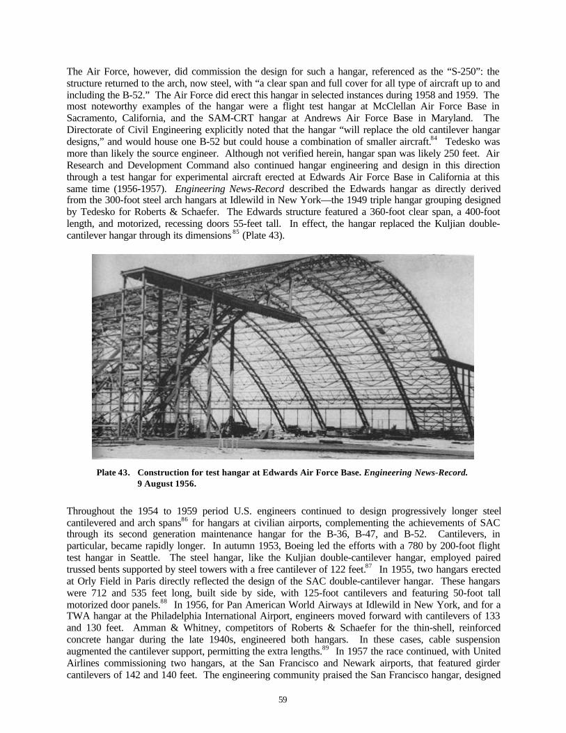
59
The Air Force, however, did commission the design for such a hangar, referenced as the “S-250”: thestructure returned to the arch, now steel, with “a clear span and full cover for all type of aircraft up to andincluding the B-52.” The Air Force did erect this hangar in selected instances during 1958 and 1959. Themost noteworthy examples of the hangar were a flight test hangar at McClellan Air Force Base inSacramento, California, and the SAM-CRT hangar at Andrews Air Force Base in Maryland. TheDirectorate of Civil Engineering explicitly noted that the hangar “will replace the old cantilever hangardesigns,” and would house one B-52 but could house a combination of smaller aircraft.84 Tedesko wasmore than likely the source engineer. Although not verified herein, hangar span was likely 250 feet. AirResearch and Development Command also continued hangar engineering and design in this directionthrough a test hangar for experimental aircraft erected at Edwards Air Force Base in California at thissame time (1956-1957). Engineering News-Record described the Edwards hangar as directly derivedfrom the 300-foot steel arch hangars at Idlewild in New York—the 1949 triple hangar grouping designedby Tedesko for Roberts & Schaefer. The Edwards structure featured a 360-foot clear span, a 400-footlength, and motorized, recessing doors 55-feet tall. In effect, the hangar replaced the Kuljian double-cantilever hangar through its dimensions 85 (Plate 43).
Plate 43. Construction for test hangar at Edwards Air Force Base. Engineering News-Record.9 August 1956.
Throughout the 1954 to 1959 period U.S. engineers continued to design progressively longer steelcantilevered and arch spans86 for hangars at civilian airports, complementing the achievements of SACthrough its second generation maintenance hangar for the B-36, B-47, and B-52. Cantilevers, inparticular, became rapidly longer. In autumn 1953, Boeing led the efforts with a 780 by 200-foot flighttest hangar in Seattle. The steel hangar, like the Kuljian double-cantilever hangar, employed pairedtrussed bents supported by steel towers with a free cantilever of 122 feet.87 In 1955, two hangars erectedat Orly Field in Paris directly reflected the design of the SAC double-cantilever hangar. These hangarswere 712 and 535 feet long, built side by side, with 125-foot cantilevers and featuring 50-foot tallmotorized door panels.88 In 1956, for Pan American World Airways at Idlewild in New York, and for aTWA hangar at the Philadelphia International Airport, engineers moved forward with cantilevers of 133and 130 feet. Amman & Whitney, competitors of Roberts & Schaefer for the thin-shell, reinforcedconcrete hangar during the late 1940s, engineered both hangars. In these cases, cable suspensionaugmented the cantilever support, permitting the extra lengths.89 In 1957 the race continued, with UnitedAirlines commissioning two hangars, at the San Francisco and Newark airports, that featured girdercantilevers of 142 and 140 feet. The engineering community praised the San Francisco hangar, designed

60
Plate 44. Skidmore, Owings & Merrill. United Airlines hangar, San Francisco International Airport.Engineering News-Record . 23 April 1959.
Plate 45. Skidmore, Owings & Merrill. Cantilever construction for United Airlines hangar, San FranciscoInternational Airport. Engineering News-Record . 30 January 1958.
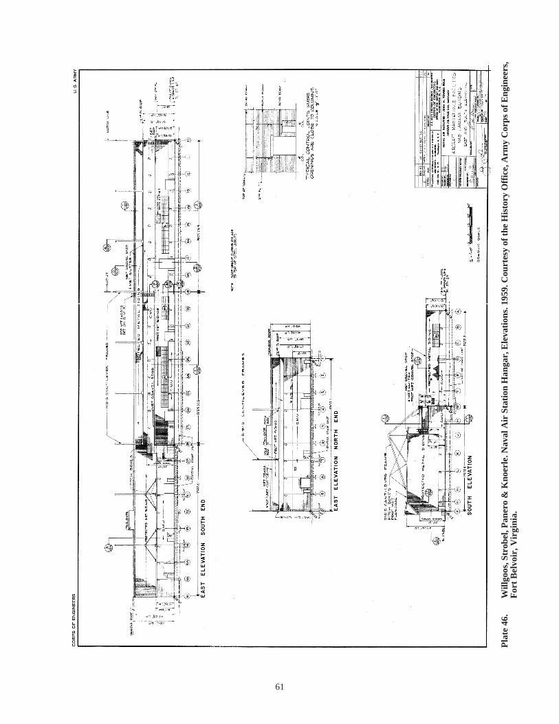
61
Pla
te 4
6.
Will
goos
, Str
obel
, Pan
ero
& K
noer
le. N
aval
Air
Sta
tion
Han
gar,
Ele
vati
ons.
195
9. C
ourt
esy
of th
e H
isto
ry O
ffic
e, A
rmy
Cor
ps o
f Eng
inee
rs,
For
t B
elvo
ir, V
irgi
nia.
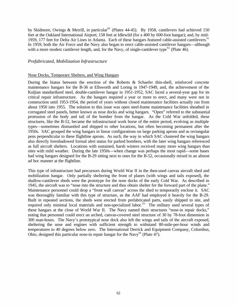
62
by Skidmore, Owings & Merrill, in particular90 (Plates 44-45). By 1958, cantilevers had achieved 150feet at the Oakland International Airport; 158 feet at Idlewild (for a 400 by 600-foot hangar); and, by mid-1959, 177 feet for Delta Air Lines in Atlanta. Each of these hangars featured cable-assisted cantilevers.91
In 1959, both the Air Force and the Navy also began to erect cable-assisted cantilever hangars—althoughwith a more modest cantilever length, and, for the Navy, of single-cantilever type92 (Plate 46).
Prefabricated, Mobilization Infrastructure
Nose Docks, Temporary Shelters, and Wing Hangars
During the hiatus between the erection of the Roberts & Schaefer thin-shell, reinforced concretemaintenance hangars for the B-36 at Ellsworth and Loring in 1947-1949, and, the achievement of theKuljian standardized steel, double-cantilever hangar in 1951-1952, SAC faced a several-year gap for itscritical repair infrastructure. As the hangars required a year or more to erect, and many were not inconstruction until 1953-1954, the period of years without closed maintenance facilities actually ran fromabout 1950 into 1955. The solution to this issue was open steel-frame maintenance facilities sheathed incorrugated steel panels, better known as nose docks and wing hangars. “Open” referred to the substantialprotrusion of the body and tail of the bomber from the hangar. As the Cold War unfolded, thesestructures, like the B-52, became the infrastructural work horse of the entire period, evolving as multipletypes—sometimes dismantled and shipped to other locations, but often becoming permanent after the1950s. SAC grouped the wing hangars in linear configurations on large parking aprons and as rectangularpens perpendicular to these flightline aprons. As such, the way in which SAC clustered the wing hangarsalso directly foreshadowed formal alert status for parked bombers, with the later wing hangars referencedas full aircraft shelters. Locations with sustained, harsh winters received many more wing hangars thansites with mild weather. During the late 1950s—when change was perhaps the most rapid—some baseshad wing hangars designed for the B-29 sitting next to ones for the B-52, occasionally mixed in an almostad hoc manner at the flightline.
This type of infrastructure had precursors during World War II in the then-used canvas aircraft shed andmobilization hangar. Only partially sheltering the front of planes (with wings and tails exposed), theshallow-cantilever sheds were the prototype for the nose docks of the early Cold War. As described in1945, the aircraft was to “nose into the structure and thus obtain shelter for the forward part of the plane.”Maintenance personnel could drop a “front wall canvas” across the shed to temporarily enclose it. SACwas thoroughly familiar with this type of structure, as the AAF had employed it heavily for the B-29.Built in repeated sections, the sheds were erected from prefabricated parts, easily shipped to site, andrequired only minimal local materials and non-specialized labor.93 The military used several types ofthese hangars at the close of World War II. The Navy named their structures “nose-in repair docks,”noting that personnel could erect an arched, canvas-covered steel structure of 30 by 78-foot dimension in300 man-hours. The Navy’s prototypical nose dock also left the wings and tails of the aircraft exposed,sheltering the nose and engines with sufficient strength to withstand 80-mile-per-hour winds andtemperatures to 40 degrees below zero. The International Derrick and Equipment Company, Columbus,Ohio, designed this particular nose-in repair hangar for the Navy94 (Plate 47).

63
Plate 47. Navy Nose-In Dock. Engineering News-Record . 22 March 1945.
The Air Force apparently used a similar dock to that of the Navy, likely designed for the B-29, after 1945.This structure, larger than the Navy’s nose-in dock and not yet verified via photographs, is mapped into1957 on flightlines at 12 installations in nearly 100 units as a semi-circular/oval footprint. Notable basesof the late 1950s with this very early nose dock were heavily in the southern United States, and includedAltus (Oklahoma), Barksdale (Louisiana), Dyess (Texas), Homestead (Florida), Hunter (Georgia), LakeCharles (Louisiana), Little Rock (Arkansas), MacDill (Florida), March (California), Pinecastle (Florida),Schilling (Kansas), and Shaw (South Carolina)95 (Plate 48). This dock is of unknown dimensions, butwas likely a slightly scaled-down version of AAF steel-arch hangars of this same period, with canvasroofs and two-piece door flaps. The full-size hangars typically were 130 by 160 feet, and 160 by 200 feet,in plan. Initial manufacturers included the Armco Drainage and Metal Products Company of Ohio andthe Stran-Steel Division of the Great Lakes Steel Corporation. AAF engineers internally designed twostandardized hangars of this type in 1944, with a pilot model erected in Melrose Park, Illinois, at the plantof the Mississippi Valley Structural Steel Company96 (Plates 49-54). During 1951 (if not before), at thewarmer-weather bases of Biggs (Texas) for the B-50; and Carswell (Texas) and Walker (New Mexico)for the B-36, and at Ellsworth adjacent to the Roberts & Schaefer thin-shell hangar, SAC was also usingmoveable engine and wing docks of two types—one of an arched steel-frame type with a canvascovering, with individual docks for each engine of the B-50, and, a second of a steel-frame structure openon its front and sides, with docks for each wing of the B-36. Maintenance personnel wheeled thesestructures in place97 (Plates 55-57). As of early 1952, SAC continued to plan for additional bomber nosedocks appropriate to the World War II aircraft. Mills & Petticord produced single drawings for nosedocks for the B-29 and B-50 (essentially a modified B-29) in March. These docks do not appear to havebeen built.98
The earliest uncovered drawings for SAC very heavy bomber nose docks, soon called wing hangars, dateto January 1951, and are a part of the mobilization effort for the Korean War. From extant Air Forcephotographs, it is additionally clear that engine docks were already in use at some installations and that
64
Pla
te 4
8.
Gro
upin
gs o
f th
ree
and
four
B-2
9 no
se d
ocks
at
the
flig
htlin
e. A
lso,
tw
o do
uble
-can
tile
ver
hang
ars.
Pin
ecas
tle
Air
For
ce B
ase.
Dir
ecto
rate
of
Ins
talla
tion
s. M
aste
r P
lan
of O
ctob
er 1
957.
Col
lect
ion
of K
.J. W
eitz
e.
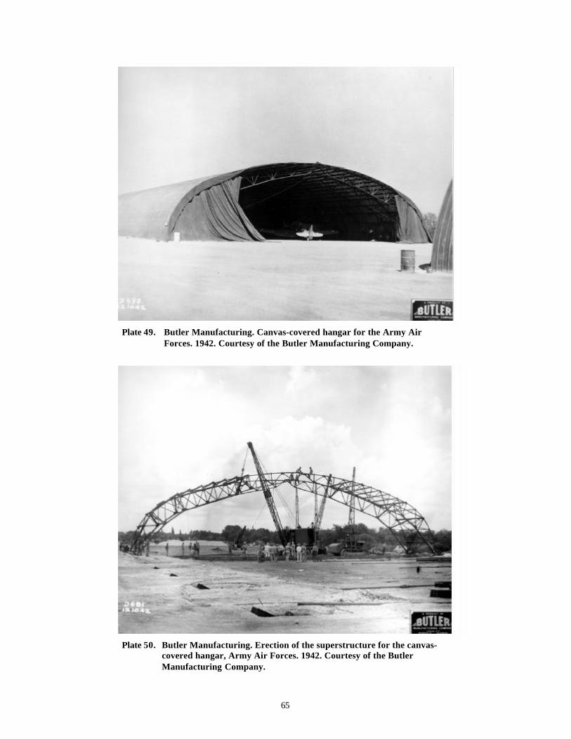
65
Plate 49. Butler Manufacturing. Canvas-covered hangar for the Army AirForces. 1942. Courtesy of the Butler Manufacturing Company.
Plate 50. Butler Manufacturing. Erection of the superstructure for the canvas-covered hangar, Army Air Forces. 1942. Courtesy of the ButlerManufacturing Company.
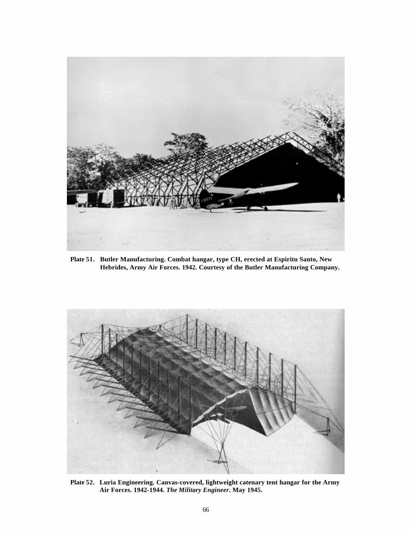
66
Plate 51. Butler Manufacturing. Combat hangar, type CH, erected at Espiritu Santo, NewHebrides, Army Air Forces. 1942. Courtesy of the Butler Manufacturing Company.
Plate 52. Luria Engineering. Canvas-covered, lightweight catenary tent hangar for the ArmyAir Forces. 1942-1944. The Military Engineer. May 1945.

67
Plate 53. Army Air Forces. Steel combat hangar. Avon Park, Florida. Bombing range forMacDill Air Force Base. View of 1995. Courtesy of Mariah Associates, Inc.
Plate 54. Butler Manufacturing. Prefabricated hangar for the Army Air Forces, with steeldoors and roof. 1945. The Military Engineer. May 1945.

68
Plate 55. Moveable repair docks for the engines of the B-50. Biggs Air Force Base.14 September 1951. Courtesy of the Air Force Historical ResearchAgency.
Plate 56. B-36 and moveable wing docks. Walker Air Force Base. 28 August1952. Courtesy of the Air Force Historical Research Agency.
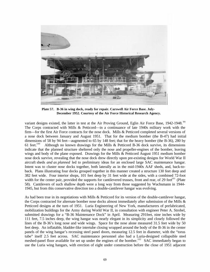
69
Plate 57. B-36 in wing dock, ready for repair. Carswell Air Force Base. July-December 1952. Courtesy of the Air Force Historical Research Agency.
variant designs existed, the latter in test at the Air Proving Ground, Eglin Air Force Base, 1942-1948. 99
The Corps contracted with Mills & Petticord—in a continuance of late 1940s military work with thefirm—for the first Air Force contracts for the nose dock. Mills & Petticord completed several versions ofa nose dock between January and August 1951. That for the medium bomber (the B-47) had initialdimensions of 58 by 94 feet—augmented to 65 by 148 feet; that for the heavy bomber (the B-36), 280 by61 feet.100 Although no known drawings for the Mills & Petticord B-36 dock survive, its dimensionsindicate that the planned structure sheltered only the nose and propeller-engines of the bomber, leavingwings and body of the plane exposed. Drawings for the Mills & Petticord August 1951 medium bombernose dock survive, revealing that the nose dock drew directly upon pre-existing designs for World War IIaircraft sheds and as planned led to preliminary ideas for an enclosed large SAC maintenance hangar.Intent was to cluster nose docks together, both laterally as in the mid-1940s AAF sheds, and, back-to-back. Plans illustrating four docks grouped together in this manner created a structure 130 feet deep and382 feet wide. Four interior shops, 101 feet deep by 31 feet wide at the sides, with a combined 72-footwidth for the center pair, provided the supports for cantilevered trusses, front and rear, of 29 feet101 (Plate58). Cantilevers of such shallow depth were a long way from those suggested by Wachsmann in 1944-1945, but from this conservative direction too a double-cantilever hangar was evolving.
As had been true in its negotiations with Mills & Petticord for its version of the double-cantilever hangar,the Corps contracted for alternate bomber nose docks almost immediately after submission of the Mills &Petticord designs at the turn of 1951. Luria Engineering of New York, manufacturers of prefabricated,mobilization buildings for the Army during World War II, in consultation with engineer Peter A. Strobel,submitted drawings for a “B-36 Maintenance Dock” in April. Measuring 291feet, nine inches wide by111 feet, 7.5 inches deep, the wing hangar was nearly elegant in its simplicity and closely followed thelines of the B-36’s long nose and wide wings. Space for the nose alone measured 31.5 feet wide by 50feet deep. An inflatable, bladder-like intertube closing wrapped around the body of the B-36 in the centerpanels of the wing hangar’s recessing steel panel doors, measuring 12.5 feet in diameter, with the “torustube” itself 2.5 feet across. SAC maintenance personnel also had a Luria-designed collapsible steelmeshed-panel floor available for set up under the engines of the bomber.102 SAC immediately began touse the Luria wing hangars, with erection of eight under construction before the close of 1951 adjacent

70
Pla
te 5
8.
Mill
s &
Pet
tico
rd. M
ediu
m B
ombe
r N
ose
Doc
k, E
leva
tion
s, P
lans
and
Sec
tion
. Aug
ust
1951
. Cou
rtes
y of
the
His
tory
Off
ice,
Arm
y C
orps
of
Eng
inee
rs, F
ort
Bel
voir
, Vir
gini
a.
71
to its Roberts & Schaefer thin-shell concrete hangars at Loring and Ellsworth Air Force Bases103 (Plates59-60). These 1951 B-36 wing hangars represented a transitional solution, and as interpreted throughinfrastructural footprints on the Air Force-wide installation master plans of 1957, appear to be correlateddirectly with the placement of alert Q Areas—special weapons storage depots for atomic bombcomponents—at installations with severe winter weather. In September 1952, SAC added three“explosion-proof telephones” at each dock, suggesting that the command was aware of the need for somelevel of blast-resistant construction and that the hangars were interpreted as minimally likely to surviveinterior aircraft explosion. 104 SAC appears to have employed these structures at Ellsworth (SouthDakota), Fairchild (Washington), Loring (Maine), and Westover (New York), with their total originallynumbering about 32. 105 At Ellsworth, SAC ran tests on their heating in early 1953, to obtain informationfor revised criteria applicable for future wing hangars.106 These structures today are rare. Those atEllsworth, Fairchild, and Loring were extant as of 1995; those at Westover are of unknown status.107
Luria (possibly again with engineer Strobel) likely also designed and manufactured a wing hangar for theB-47 at this same time. The B-47 first entered SAC inventory in October 1951. Although drawings havenot been found for this dock, its footprint is also distinctive, and, like the Luria-Strobel wing hangar forthe B-36, very closely mimics the shape of the bomber’s nose and wings. Photographs of a cluster ofeight B-47 docks do survive for McConnell Air Force Base in Kansas, showing just how remarkably thestructure followed the swept-back form of the B-47.108 This hangar was in use at early B-47 installations,as well as at ones where the numbers of the aircraft were high and SAC training programs were active,inclusive of McConnell in Kansas; Lincoln in Nebraska; and Castle in California 109 (Plates 61-65).Construction of the structure likely dates to 1952-1953, paralleling the arrival of the B-47 at SAC bases.By 1957 the Air Force still planned to ship it to selected bases using the B-47, inclusive of Anderson inGuam. 110 Numbers of B-47 wing hangars were similar to those for the B-36. The Air Force mapped thisdock at only five installations in 1957: Altus (Oklahoma); Anderson (Guam); Castle (California); Lincoln(Nebraska); and March (California). The Castle and Lincoln configurations are classic for the dock’sstate-of-the-art B-47 use. By this date, however, SAC was already dismantling these docks and shippingthem to installations accepting a variety of surplus docks, or, to installations receiving the B-47 late in itslife. For example, McConnell had eight of the B-47 docks configured in a proto-alert configuration in themiddle 1950s, but completely gone by late 1957. At this same time, SAC planned for Anderson (Guam),with six B-47 docks, to receive 12 more. Survival of the B-47 dock in the continental United Statesappears very infrequent and in the one known instance at Seymour-Johnson Air Force Base in NorthCarolina is likely an example of surplus availability and alternate use, as the base never received the B-47.111
By mid-August 1951, Luria had begun design efforts for a more versatile SAC wing hangar than either ofthe two intended explicitly for the B-36 or the B-47. Luria’s multi-purpose wing hangar accommodatedconfigurations of the B-29 / B-50 (two), the B-36 (one), the B-47 (two), and the as yet only planned B-52(one), measuring approximately 124 feet deep by 296.5 feet wide.112 The Luria multi-purpose winghangars continued to minimize enclosed space—closely following the dimensions of the bombersintended for service in a stepped configuration widest for the aircraft wings and only about 40 feet deepby 36 feet wide for the aircraft nose. The nose space met the requirements of the B-52, and was onlypartially deep enough for the B-36.113 The Luria multi-purpose wing hangars continued to bemobilization structures, intended for efficient erection and with the potential for takedown and shipmentto a new installation. The Luria multi-purpose dock went through rapid minor revisions during 1952,altering the width and depth in increments of less than two feet.114 By early 1953, the Luria multi-purpose wing hangar was under construction at selected installations, continuing to be erected from the1952 drawings well into 1955. Luria wing hangars were planned as multiples, but in placement side byside, not back to back as suggested at the outset of 1951 by Mills & Petticord (Plates 66-74).
By early 1953, the Air Force authorized SAC headquarters at Offutt Air Force Base in Omaha to developthe definitive criteria for warm-climate, multi-purpose docks.115 Andrus Martin Associates of Omahasubmitted drawings for the definitive SAC multi-purpose wing hangar in August 1953—most likely
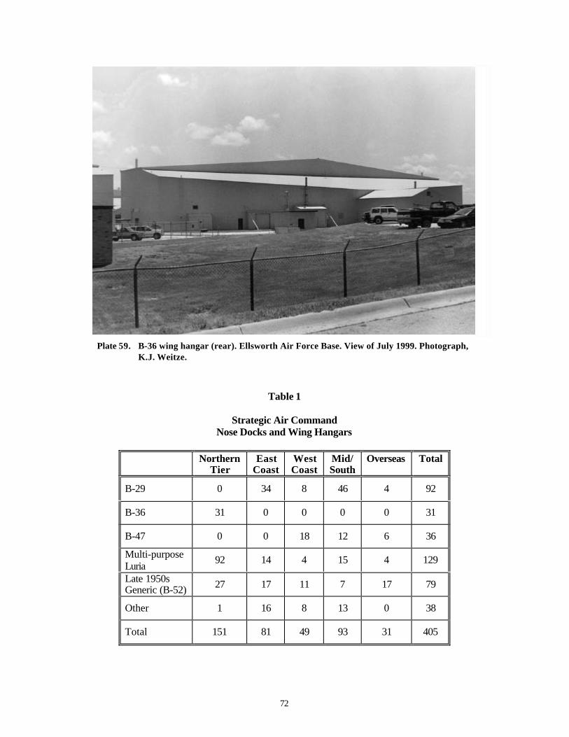
72
Plate 59. B-36 wing hangar (rear). Ellsworth Air Force Base. View of July 1999. Photograph,K.J. Weitze.
Table 1
Strategic Air CommandNose Docks and Wing Hangars
NorthernTier
EastCoast
WestCoast
Mid/South
Overseas Total
B-29 0 34 8 46 4 92
B-36 31 0 0 0 0 31
B-47 0 0 18 12 6 36
Multi-purposeLuria
92 14 4 15 4 129
Late 1950sGeneric (B-52) 27 17 11 7 17 79
Other 1 16 8 13 0 38
Total 151 81 49 93 31 405

73
Pla
te 6
0.
Gro
upin
g of
eig
ht B
-36
win
g ha
ngar
s, m
idgr
ound
rig
ht. G
roup
ing
of 1
7 m
ulti
-pur
pose
and
B-5
2 w
ing
hang
ars,
mid
grou
nd le
ft. T
hin-
shel
l co
ncre
te B
-36
hang
ar, c
ente
r. P
lann
ed S
AC
ale
rt, r
ight
. Ells
wor
th A
ir F
orce
Bas
e. D
irec
tora
te o
f In
stal
lati
ons.
Mas
ter
Pla
n of
Oct
ober
19
57. C
olle
ctio
n of
K.J
. Wei
tze.

74
Plate 61. Groupings of six (foreground) and two (midground) B-47 wing hangars.McConnell Air Force Base. 1952. Courtesy of the History Office,McConnell Air Force Base.
Plate 62. B-47 in flight. View of 1956. Courtesy of the Air Force Historical Research Agency.
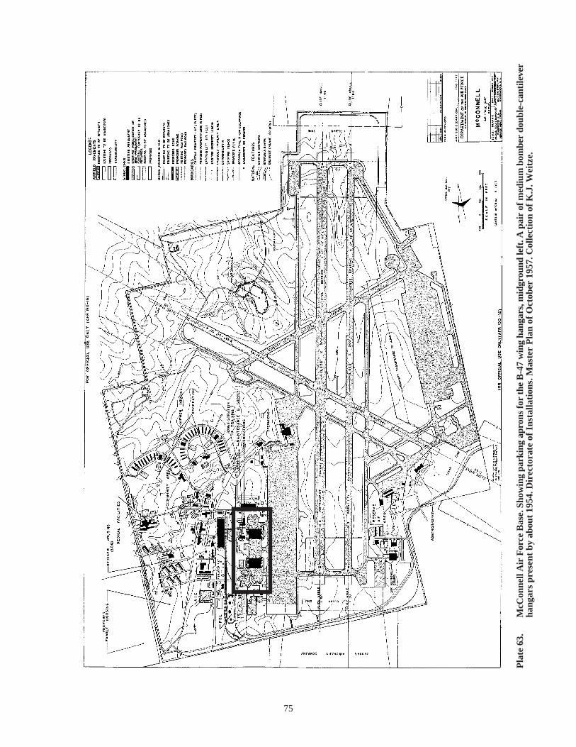
75
Pla
te 6
3.
McC
onne
ll A
ir F
orce
Bas
e. S
how
ing
park
ing
apro
ns fo
r th
e B
-47
win
g ha
ngar
s, m
idgr
ound
left
. A p
air
of m
ediu
m b
ombe
r do
uble
-can
tile
ver
hang
ars
pres
ent
by a
bout
195
4. D
irec
tora
te o
f In
stal
lati
ons.
Mas
ter
Pla
n of
Oct
ober
195
7. C
olle
ctio
n of
K.J
. Wei
tze.

76
Pla
te 6
4.
Cas
tle
Air
For
ce B
ase.
Gro
upin
gs o
f ni
ne a
nd f
ive
B-4
7 w
ing
hang
ars,
par
alle
l and
per
pend
icul
ar t
o th
e fl
ight
line.
Hea
vy b
ombe
r do
uble
-ca
ntile
ver
hang
ar, w
ith
smal
ler
grou
ping
and
pla
nned
SA
C a
lert
, rig
ht. D
irec
tora
te o
f Ins
talla
tion
s. M
aste
r P
lan
of O
ctob
er 1
957.
Col
lect
ion
of K
.J. W
eitz
e.
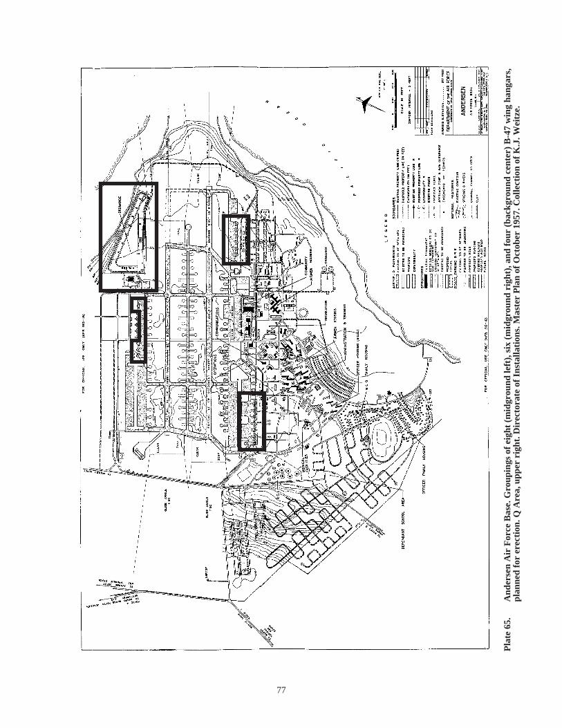
77
Pla
te 6
5.
And
erse
n A
ir F
orce
Bas
e. G
roup
ings
of
eigh
t (m
idgr
ound
left
), s
ix (
mid
grou
nd r
ight
), a
nd f
our
(bac
kgro
und
cent
er)
B-4
7 w
ing
hang
ars,
pl
anne
d fo
r er
ecti
on. Q
Are
a, u
pper
rig
ht. D
irec
tora
te o
f In
stal
lati
ons.
Mas
ter
Pla
n of
Oct
ober
195
7. C
olle
ctio
n of
K.J
. Wei
tze.

78
Pla
te 6
6.
Lur
ia E
ngin
eeri
ng. M
ulti
-pur
pose
win
g ha
ngar
. Aug
ust
1951
. Cou
rtes
y of
the
His
tory
Off
ice,
Arm
y C
orps
of
Eng
inee
rs, F
ort
Bel
voir
, V
irgi
nia.

79
Plate 67. Luria Engineering. Multi-purpose wing hangars. Ellsworth Air Force Base. Frontoblique view, July 1999. Photograph, K.J. Weitze.
Plate 68. Luria Engineering. Multi-purpose wing hangars. Ellsworth Air Force Base. Rearoblique view, July 1999. Photograph, K.J. Weitze.

80
Plate 69. Luria Engineering. Multi-purpose wing hangars. Ellsworth Air Force Base. Frontfull view, July 1999. Photograph, K.J. Weitze.
Plate 70. Luria Engineering. Multi-purpose wing hangar at the former Loring Air Force Base.View of 1995. Courtesy of Mariah Associates, Inc.

81
Plate 71. Luria Engineering. Multi-purpose wing hangar at the former Lincoln Air ForceBase. Front view, July 1999. Photograph, K.J. Weitze.
Plate 72. Luria Engineering. Multi-purpose wing hangar at the former Lincoln Air ForceBase. Rear view, July 1999. Photograph, K.J. Weitze.

82
Plate 73. Luria Engineering. Multi-purpose wing hangar. Whiteman Air Force Base. Rearview, July 1999. Photograph, K.J. Weitze.
Plate 74. Luria Engineering. Multi-purpose wing hangars at the former Forbes Air ForceBase. Front oblique view, July 1999. Photograph, K.J. Weitze.
83
working from Luria baseline designs. SAC distributed the specifications for this wing hangar to Corpsdistrict offices out of Seattle, Charleston, Savannah, the Eastern Atlantic, and the Middle East.116 Actualconstruction from these definitives is unknown. Engineer Peter A. Strobel re-entered the design picturefor the docks in early 1953, with a formal Strobel & Salzman revision of the Luria multi-purpose wingdock of 1952. The number of sheets associated with the dock increased from 27 to 39 with this effort.117
Strobel had gone into partnership with Salzman after his work with Luria on the B-36 dock in early 1951,designing one of the first ADC alert hangars shortly thereafter. Progress on the docks continued to beevolutionary in type, with historic lineage confusing and ties to the basic Luria 1952 design sometimesobscured. In 1955, Kuljian—the engineers of the double-cantilever hangar—also executed a formalrevision of the dock for SAC.118 The total multi-purpose dock grouping, in all of its variations, numberedabout 130 units at 23 bases by late 1957.119
During the next several years—with the Kuljian double-cantilever hangar largely in place and the Kuljianformal revision of the Luria multi-purpose wing hangar the latest in the evolutionary pattern, SAC use ofwing hangars continued. SAC primarily split dock construction for its B-36s and B-47s between theLuria wing hangars of 1951 and 1952, and the ad hoc solutions wheeled into place. During the middleand late 1950s, too, SAC modified the Luria 1951 wing hangars for the B-36 to accommodate the B-52 asit replaced the B-36. Leo A. Daly, SAC’s lead firm out of Omaha, handled the modifications for thedock, adding a rectangular section across the front of the dock 36 feet deep and increasing the heightabove the original 38 feet.120 (See Plates 59-60.) At Loring, the 42nd Heavy Bombardment Wingmodified their eight B-36 docks with SAC assistance for receipt of the KC-135—the tankeraccompanying the B-52—in the autumn of 1957, after first attempting to work with Luria directly. 121 Thenoses of the B-52 and KC-135 filled only a minor part of the B-36 nose spatial cavity, but the extensionallowed just at 100 feet for the body of the aircraft. The wing hangar, as modified, became more nearly afull shelter for the B-52, with only tail exposed through the door. At Loring, the modifications caused astructural deterioration of the Luria wing hangars, which were considered unsafe by the late 1950s.122 AtEllsworth, the docks remain in use and appear in excellent condition today. Not until after the Air Forcediscontinued the double-cantilever hangar program in 1955, and the modified Luria B-36 and multi-purpose docks proved less than fully satisfactory for the B-52, did SAC push a next generation programof maintenance docks. In July 1956, Luria provided the Air Force with the design for a standard aircraftshelter intended primarily for the B-52. This structure measured 246.5 feet wide and 177 feet deep,completely accommodating the B-52.123 Formal revisions soon followed, with submitted drawings for thedock in early 1957.124 By late in the same year about 80 of these docks were in place at 16 bases125 (Plate75).
With the suspension of the double-cantilever hangar program—and even with the intent of replacing itwith the S-250 steel-arch hangar of 1957—SAC continued to depend heavily on the wing maintenancehangar for the buildout of the B-52 program during the late 1950s and early 1960s. The MilitaryConstruction Program of 1957-1958 (fiscal year 1958) called for 77 additional Air Force maintenancedocks, with 70 such docks (primarily for the B-52) centrally procured after mid-1957. 126 Procurement ofB-52 docks was steady and in large numbers during the late 1950s. Luria provided new baseline designsin 1957-1958, with the dock simplified to a more generic box shape about 130 feet deep and 225 feetwide.127 By 1959, the Directorate of Civil Engineering also formally noted that SAC was dismantlingolder and excess docks, shipping them to the installations with the greatest need.128 As of 1960, the AirForce directed “maximum economic use of available facilities,” conducting a “nation-wide dock analysis”in November “to determine where surplus aircraft maintenance docks were available for relocating tobases deficient in covered maintenance space.” SAC’s needs for new B-52 docks, as of this date, werestill interpreted to be 22 for fiscal year 1962, but relocation was to suffice. Congress did nonethelessappropriate over seven and one-half million dollars for 17 B-52 docks, planning for 34 new docks infiscal year 1961. As of early 1961, too, SAC commissioned its final major aircraft dock of the early ColdWar, a fuel systems dock. Ten were in planning for fiscal year 1961. The pilot SAC fuel systems dockwent under contract in March 1961 at Robins Air Force Base in Georgia for Air Materiel Command(AMC), and the first of this late 1950s SAC dock went in at the northern tier bases across Montana, North

84
Plate 75. Luria Engineering. B-52 wing hangar. Offutt Air Force Base. View of July 1999.Photograph, K.J. Weitze.
Dakota, and Michigan.129 During 1961 and 1962, SAC erected 20 new B-52 docks and eight additionalfuel systems docks, continuing to achieve some of their dock goals through relocation acrossinstallations.130
The B-52 maintenance docks of the late 1950s and early 1960s—the final evolution of the Luria winghangar of 1951—defined the next stage of the SAC landscape after that established through the double-cantilever hangar program. At full buildout, the two chief types of B-52 dock appear to have numberedabout 200. B-52 docks were typically clustered in groups of four to six, and bracketed one or moredouble-cantilever hangars where they were present. At bases where no double-cantilever hangar existed,such as those in construction after 1955, the B-52 docks alone defined the landscape. Examples of thisphenomenon include Grand Forks and Minot Air Force Bases in North Dakota.
Prefabricated Airmen Dormitories
In about 1951, SAC also undertook an experiment in prefabricated, steel airmen dormitories, partiallyreflective of steel panel housing tried Air Force-wide at about this time and of the Air Force’s formalstudy of “prefabricated structures and methods of construction.”131 The SAC turn to steel airmendormitories, however, went well beyond a mobilization solution in response to Korea. SAC picked upwhere the Army had left off in its experimental barracks project at Camp Grant, Illinois, of 1941. There,Holabird & Root—a Chicago firm also heavily participating in early Cold War design for ADC—designed eight prototype dorms, four of which were completely steel construction (and four of whichwere hollow tile and concrete block) 132 (Plate 76). SAC commissioned a limited number of three-storydormitories, in clusters of two, three, and four, beginning at its headquarters installation Offutt Air ForceBase in Omaha. These dorms went up very quickly; used highly standardized components; wereengineered for wind and vibration resistance; were especially economical; and provided a two-man roomwith connecting baths, with lounges on each floor—considered a well-deserved luxury for the SACbomber pilots and crew members who were on call to fly 24 hours a day.133 The dorms were both

85
Plate 76. Holabird & Root. Experimental steel dormitory (two of this design built). CampGrant, Illinois. Engineering News-Record . 22 May 1941.
Plate 77. Detroit Steel Products Company. SAC airmen dormitory. Pease Air Force Base.Engineering News-Record . 28 February 1957.

86
Plate 78. Concrete-block airmen dormitory, with three-man rooms. Bergstrom Air ForceBase. 1952-1953. Courtesy of the Air Force Historical Research Agency.
Plate 79. Detroit Steel Products Company. Paired SAC airmen dormitories (renovated).Ellsworth Air Force Base. View of July 1999. Photograph, K.J. Weitze.
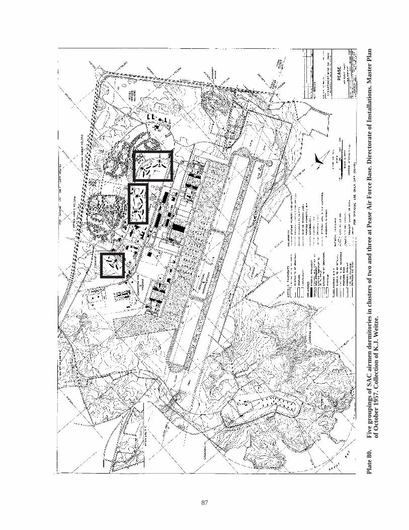
87
Pla
te 8
0.
Fiv
e gr
oupi
ngs
of S
AC
air
men
dor
mit
orie
s in
clu
ster
s of
tw
o an
d th
ree
at P
ease
Air
For
ce B
ase.
Dir
ecto
rate
of
Inst
alla
tion
s. M
aste
r P
lan
of O
ctob
er 1
957.
Col
lect
ion
of K
.J. W
eitz
e.
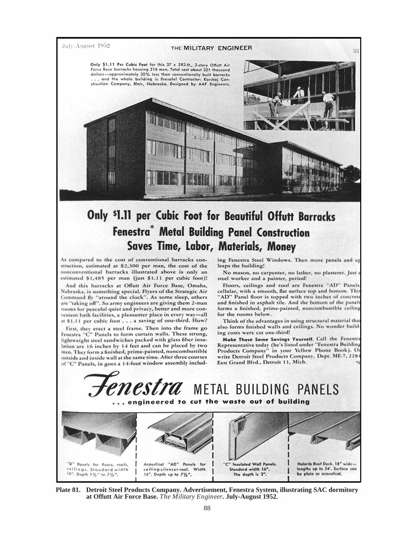
Plate 81. Detroit Steel Products Company. Advertisement, Fenestra System, illustrating SAC dormitory at Offutt Air Force Base. The Military Engineer. July-August 1952.
88

Plate 82. Detroit Steel Products Company. Advertisement, Fenestra System. The Military Engineer. May-June 1952.
89

90
Pla
te 8
3.
Det
roit
Ste
el P
rodu
cts
Com
pany
wit
h th
e A
rmy
Cor
ps o
f E
ngin
eers
, Om
aha
Dis
tric
t. S
AC
air
men
dor
mit
ory.
Dra
win
gs f
or E
llsw
orth
Air
F
orce
Bas
e da
ted
Aug
ust
1952
.
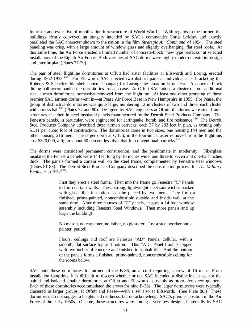
91
futuristic and evocative of mobilization infrastructure of World War II. With regards to the former, thebuildings clearly conveyed an imagery intended by SAC’s commander Curtis LeMay, and exactlyparalleled the SAC character shown to the nation in the film Strategic Air Command of 1954. The steelpaneling was crisp, with a large amount of window glass and slightly overhanging, flat steel roofs. Atthis same time, the Air Force erected a limited number of concrete-block “new type barracks” at selectedinstallations of the Eighth Air Force. Both varieties of SAC dorms were highly modern in exterior designand interior plan (Plates 77-79).
The pair of steel flightline dormitories at Offutt had sister facilities at Ellsworth and Loring, erectedduring 1952-1953.134 For Ellsworth, SAC erected two distinct pairs at individual sites bracketing theRoberts & Schaefer thin-shell concrete hangar; for Loring, the situation is unclear. A concrete-blockdining hall accompanied the dormitories in each case. At Offutt SAC added a cluster of four additionalsteel airmen dormitories, somewhat removed from the flightline. At least one other grouping of thesepremier SAC airmen dorms went in—at Pease Air Force Base in New Hampshire in 1955. For Pease, thegroup of distinctive dormitories was quite large, numbering 13 in clusters of two and three, each clusterwith a mess hall135 (Plates 77 and 80). Designed by SAC engineers at Offutt, the dorms were steel-framestructures sheathed in steel insulated panels manufactured by the Detroit Steel Products Company. TheFenestra panels, in particular, were engineered for earthquake, bomb, and fire resistance.136 The DetroitSteel Products Company advertised these airmen barracks, each 37 by 282 feet in plan, as costing only$1.11 per cubic foot of construction. The dormitories came in two sizes, one housing 144 men and theother housing 216 men. The larger dorm at Offutt, in the four-unit cluster removed from the flightline,cost $320,000, a figure about 30 percent less than that for conventional barracks.137
The dorms were considered permanent construction, and the penultimate in modernity. Fiberglassinsulated the Fenestra panels were 14 feet long by 16 inches wide, and three to seven and one-half inchesthick. The panels formed a curtain wall on the steel frame, complemented by Fenestra steel windows(Plates 81-83). The Detroit Steel Products Company described the construction process for The MilitaryEngineer in 1952138:
First they erect a steel frame. Then into the frame go Fenestra “C” Panelsto form curtain walls. These strong, lightweight steel sandwiches packedwith glass fiber insulation…can be placed by two men. They form afinished, prime-painted, noncombustible outside and inside wall at thesame time. After three courses of “C” panels, in goes a 14-foot windowassembly including Fenestra Steel Windows. Then more panels and upleaps the building!
No mason, no carpenter, no lather, no plasterer. Just a steel worker and apainter, period!
Floors, ceilings and roof are Fenestra “AD” Panels, cellular, with asmooth, flat surface top and bottom. This “AD” Panel floor is toppedwith two inches of concrete and finished in asphalt tile. And the bottomof the panels forms a finished, prime-painted, noncombustible ceiling forthe rooms below.
SAC built these dormitories for airmen of the B-36, an aircraft requiring a crew of 16 men. Frominstallation footprints, it is difficult to discern whether or not SAC intended a distinction in use for thepaired and isolated smaller dormitories at Offutt and Ellsworth—possibly as proto-alert crew quarters.Each of these dormitories accommodated the crews for nine B-36s. The larger dormitories were typicallyclustered in larger groups, at Offutt and Pease—with a set also at Ellsworth. (See Plate 80.) Thesedormitories do not suggest a heightened readiness, but do acknowledge SAC’s premier position in the AirForce of the early 1950s. Of note, these structures were among a very few designed internally by SAC
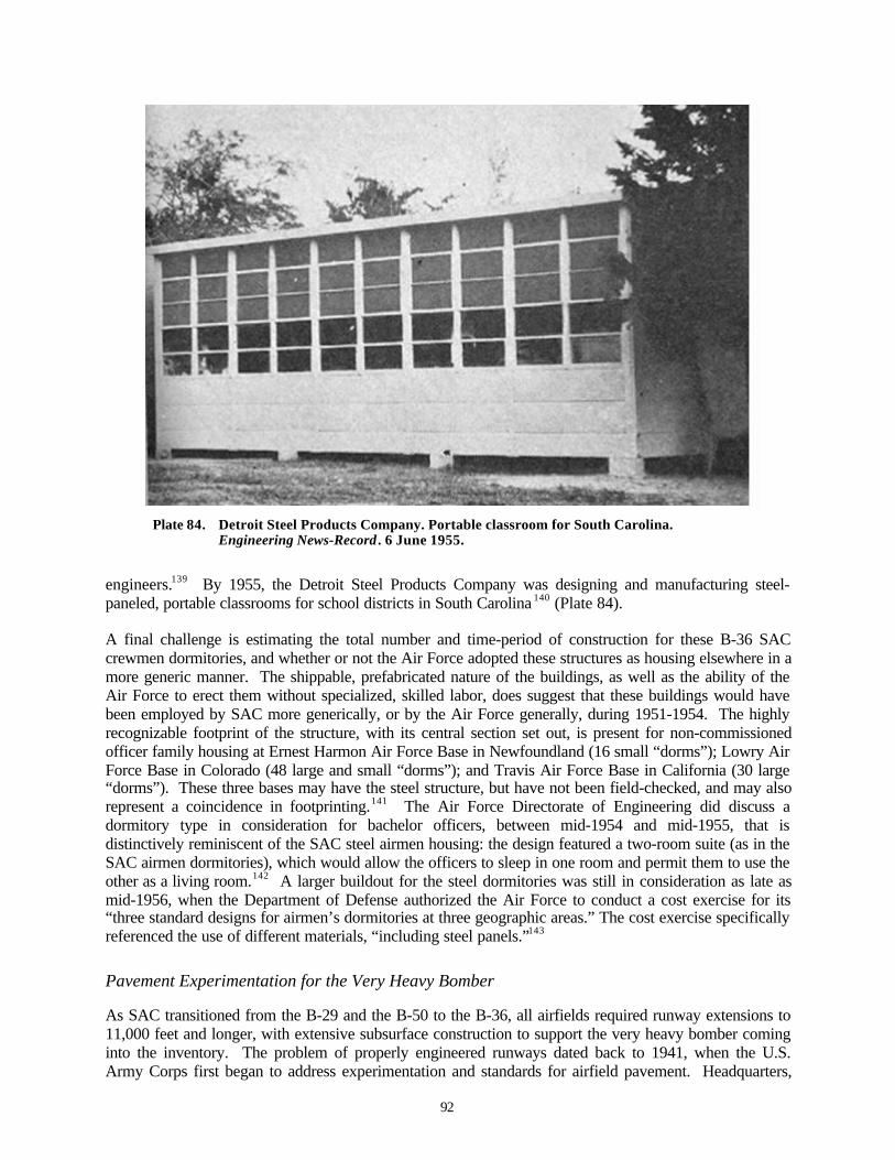
92
Plate 84. Detroit Steel Products Company. Portable classroom for South Carolina.Engineering News-Record . 6 June 1955.
engineers.139 By 1955, the Detroit Steel Products Company was designing and manufacturing steel-paneled, portable classrooms for school districts in South Carolina 140 (Plate 84).
A final challenge is estimating the total number and time-period of construction for these B-36 SACcrewmen dormitories, and whether or not the Air Force adopted these structures as housing elsewhere in amore generic manner. The shippable, prefabricated nature of the buildings, as well as the ability of theAir Force to erect them without specialized, skilled labor, does suggest that these buildings would havebeen employed by SAC more generically, or by the Air Force generally, during 1951-1954. The highlyrecognizable footprint of the structure, with its central section set out, is present for non-commissionedofficer family housing at Ernest Harmon Air Force Base in Newfoundland (16 small “dorms”); Lowry AirForce Base in Colorado (48 large and small “dorms”); and Travis Air Force Base in California (30 large“dorms”). These three bases may have the steel structure, but have not been field-checked, and may alsorepresent a coincidence in footprinting.141 The Air Force Directorate of Engineering did discuss adormitory type in consideration for bachelor officers, between mid-1954 and mid-1955, that isdistinctively reminiscent of the SAC steel airmen housing: the design featured a two-room suite (as in theSAC airmen dormitories), which would allow the officers to sleep in one room and permit them to use theother as a living room.142 A larger buildout for the steel dormitories was still in consideration as late asmid-1956, when the Department of Defense authorized the Air Force to conduct a cost exercise for its“three standard designs for airmen’s dormitories at three geographic areas.” The cost exercise specificallyreferenced the use of different materials, “including steel panels.”143
Pavement Experimentation for the Very Heavy Bomber
As SAC transitioned from the B-29 and the B-50 to the B-36, all airfields required runway extensions to11,000 feet and longer, with extensive subsurface construction to support the very heavy bomber cominginto the inventory. The problem of properly engineered runways dated back to 1941, when the U.S.Army Corps first began to address experimentation and standards for airfield pavement. Headquarters,
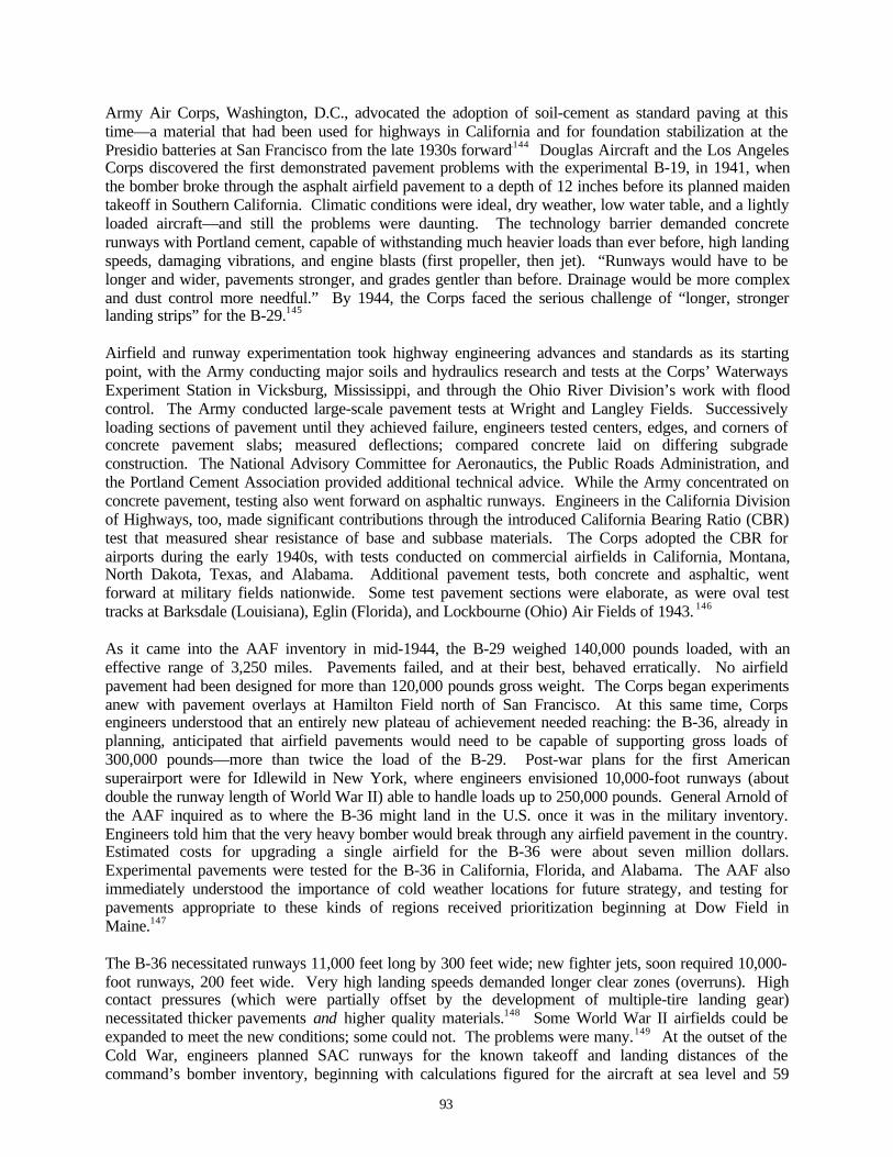
93
Army Air Corps, Washington, D.C., advocated the adoption of soil-cement as standard paving at thistime—a material that had been used for highways in California and for foundation stabilization at thePresidio batteries at San Francisco from the late 1930s forward.144 Douglas Aircraft and the Los AngelesCorps discovered the first demonstrated pavement problems with the experimental B-19, in 1941, whenthe bomber broke through the asphalt airfield pavement to a depth of 12 inches before its planned maidentakeoff in Southern California. Climatic conditions were ideal, dry weather, low water table, and a lightlyloaded aircraft—and still the problems were daunting. The technology barrier demanded concreterunways with Portland cement, capable of withstanding much heavier loads than ever before, high landingspeeds, damaging vibrations, and engine blasts (first propeller, then jet). “Runways would have to belonger and wider, pavements stronger, and grades gentler than before. Drainage would be more complexand dust control more needful.” By 1944, the Corps faced the serious challenge of “longer, strongerlanding strips” for the B-29.145
Airfield and runway experimentation took highway engineering advances and standards as its startingpoint, with the Army conducting major soils and hydraulics research and tests at the Corps’ WaterwaysExperiment Station in Vicksburg, Mississippi, and through the Ohio River Division’s work with floodcontrol. The Army conducted large-scale pavement tests at Wright and Langley Fields. Successivelyloading sections of pavement until they achieved failure, engineers tested centers, edges, and corners ofconcrete pavement slabs; measured deflections; compared concrete laid on differing subgradeconstruction. The National Advisory Committee for Aeronautics, the Public Roads Administration, andthe Portland Cement Association provided additional technical advice. While the Army concentrated onconcrete pavement, testing also went forward on asphaltic runways. Engineers in the California Divisionof Highways, too, made significant contributions through the introduced California Bearing Ratio (CBR)test that measured shear resistance of base and subbase materials. The Corps adopted the CBR forairports during the early 1940s, with tests conducted on commercial airfields in California, Montana,North Dakota, Texas, and Alabama. Additional pavement tests, both concrete and asphaltic, wentforward at military fields nationwide. Some test pavement sections were elaborate, as were oval testtracks at Barksdale (Louisiana), Eglin (Florida), and Lockbourne (Ohio) Air Fields of 1943. 146
As it came into the AAF inventory in mid-1944, the B-29 weighed 140,000 pounds loaded, with aneffective range of 3,250 miles. Pavements failed, and at their best, behaved erratically. No airfieldpavement had been designed for more than 120,000 pounds gross weight. The Corps began experimentsanew with pavement overlays at Hamilton Field north of San Francisco. At this same time, Corpsengineers understood that an entirely new plateau of achievement needed reaching: the B-36, already inplanning, anticipated that airfield pavements would need to be capable of supporting gross loads of300,000 pounds—more than twice the load of the B-29. Post-war plans for the first Americansuperairport were for Idlewild in New York, where engineers envisioned 10,000-foot runways (aboutdouble the runway length of World War II) able to handle loads up to 250,000 pounds. General Arnold ofthe AAF inquired as to where the B-36 might land in the U.S. once it was in the military inventory.Engineers told him that the very heavy bomber would break through any airfield pavement in the country.Estimated costs for upgrading a single airfield for the B-36 were about seven million dollars.Experimental pavements were tested for the B-36 in California, Florida, and Alabama. The AAF alsoimmediately understood the importance of cold weather locations for future strategy, and testing forpavements appropriate to these kinds of regions received prioritization beginning at Dow Field inMaine.147
The B-36 necessitated runways 11,000 feet long by 300 feet wide; new fighter jets, soon required 10,000-foot runways, 200 feet wide. Very high landing speeds demanded longer clear zones (overruns). Highcontact pressures (which were partially offset by the development of multiple-tire landing gear)necessitated thicker pavements and higher quality materials.148 Some World War II airfields could beexpanded to meet the new conditions; some could not. The problems were many.149 At the outset of theCold War, engineers planned SAC runways for the known takeoff and landing distances of thecommand’s bomber inventory, beginning with calculations figured for the aircraft at sea level and 59

94
degrees Fahrenheit. The engineers then adjusted for elevation and average maximum temperatures,adjusting further for safety. In 1950, SAC runways for the B-47 required ten “battalion” months to build;for the B-36, 18 battalion months—an increase of 50 percent in time over that needed to accommodate theB-29. Generally, two battalions provided the workforce for construction, with SAC runway constructiontime varying from five to nine months under optimal conditions.150
The Air Force built two types of runways during this period: asphaltic and concrete. Concrete pavementwas considerably more expensive, although the Air Force strongly preferred it and scheduled the materialat permanent (25-year) bases. High temperatures, jet blasts, and spillage of jet fuel damaged asphalticrunways more seriously than these factors affected concrete, and in either case, jet blasts eroded runwayshoulders while jet engines sucked in debris. Hence, runway shoulders required stabilization as the ColdWar unfolded. 151 The Air Force Directorate of Installations recorded accelerated tests for “tar-rubber”runway and airfield pavement at Hunter Air Force Base in early 1952, in hopes of developing a pavementless costly than concrete.152 Even where concrete was planned, the material was confined to hangaraccess; maintenance, fueling, and parking aprons; calibration platforms; warm-up pads; and the final 1000feet of runways.153 By mid-1953, the Air Force initiated a formal study of its runways considered“economically infeasible to extend or to be replaced with new runways.” Already at this early date, sixinstallations fell into this category.154 The next year, 1954, Air Force concern over the asphalt versusconcrete dilemma reached its height, and the Secretary of Defense requested that the National Academyof Sciences make a separate evaluation. The Highway Research Board of the Academy appointed acommittee of consultants to review effects at 12 Air Force Bases and at 12 Naval Air Stations.155
Additional consultants observed pavement construction in the U.S. for monitoring airfield pavementconstruction at airfields in Great Britain. 156
During the late 1940s and the first half of the 1950s, SAC sponsored major runway work at its premierinstallations. Knowledge of cold weather runway construction benefited from engineering at Loring AirForce Base in particular.157 During 1954, the Air Force completed two of the world’s longest runways—at Kirtland Air Force Base in Albuquerque and Edwards Air Force Base in Mojave Desert of SouthernCalifornia. The Kirtland runway, accented by three SAC double-cantilever maintenance hangars,featured a subgrade compacted earth 17 to 20 inches thick; a base grade of compacted gravel and stoneeight to 13 inches thick; and a top four-inch layer of asphalt. The 1000-foot ends of the runway wereconcrete, 15 to 19 inches thick. 158 The Air Force constructed the Edwards runway entirely of concrete.At 15,000 feet in length, and with a concrete depth of 17 to 19 inches, the runway was engineered foraircraft weighing up to 500,000 pounds. Taxiways, parking aprons, warm-up pads, and the final 1000feet at each end of the runway; and, the center 500 feet of the runway; featured the maximum depth of 19inches, while the remainder of the runway featured the 17-inch concrete paving. The Air Force built theEdwards runway as a prototype for all its future runways, and as a flight test facility. 159 In an oppositedirection, SAC tried the tar-rubber paving in a major way at Homestead Air Force Base in Florida whenthat installation was refurbished for bomber dispersal in 1955. The Corps had previously only laid testsections of the tar-rubber pavement—at Dow Air Force Base in Maine in 1952. At Homestead, SACbased B-47s with a single apron of 1,150 by 8,000 feet, taxiways, warm-up pads, and the 1000-footoverruns were all tar-rubber, in addition to the primary 11,400 by 200-foot runway. The U.S. RubberCompany manufactured SAC’s tar-rubber pavement, calling it Sulfa-Aero-Sealz 3080 and shipping it inby tanker trucks from New Jersey160 (Plates 85-88).
In 1956, the Air Force finalized the asphalt-concrete controversy by adopting concrete for runwaypavement exclusively at any primary use facility. The Asphalt Institute protested this policy decision, andas one final test the Air Force constructed a test track of flexible and rigid pavement panels at Kelly AirForce Base in San Antonio. The flexible panels failed, substantiating the Air Force choice of concrete.161
More sophisticated tests of concrete pavement did continue, however. Later this same year, the Air Forcetested prestressed concrete and nominally reinforced concrete in sections constructed at Columbus AirForce Base (Mississippi), additionally studying problems of drainage design problems.162 By the end ofthe decade, SAC had lengthened its runways to a typical 13,000 to 13,500 feet at most installations. In
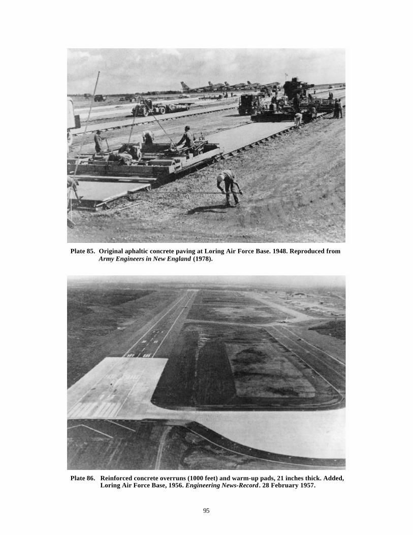
95
Plate 85. Original aphaltic concrete paving at Loring Air Force Base. 1948. Reproduced fromArmy Engineers in New England (1978).
Plate 86. Reinforced concrete overruns (1000 feet) and warm-up pads, 21 inches thick. Added,Loring Air Force Base, 1956. Engineering News-Record . 28 February 1957.
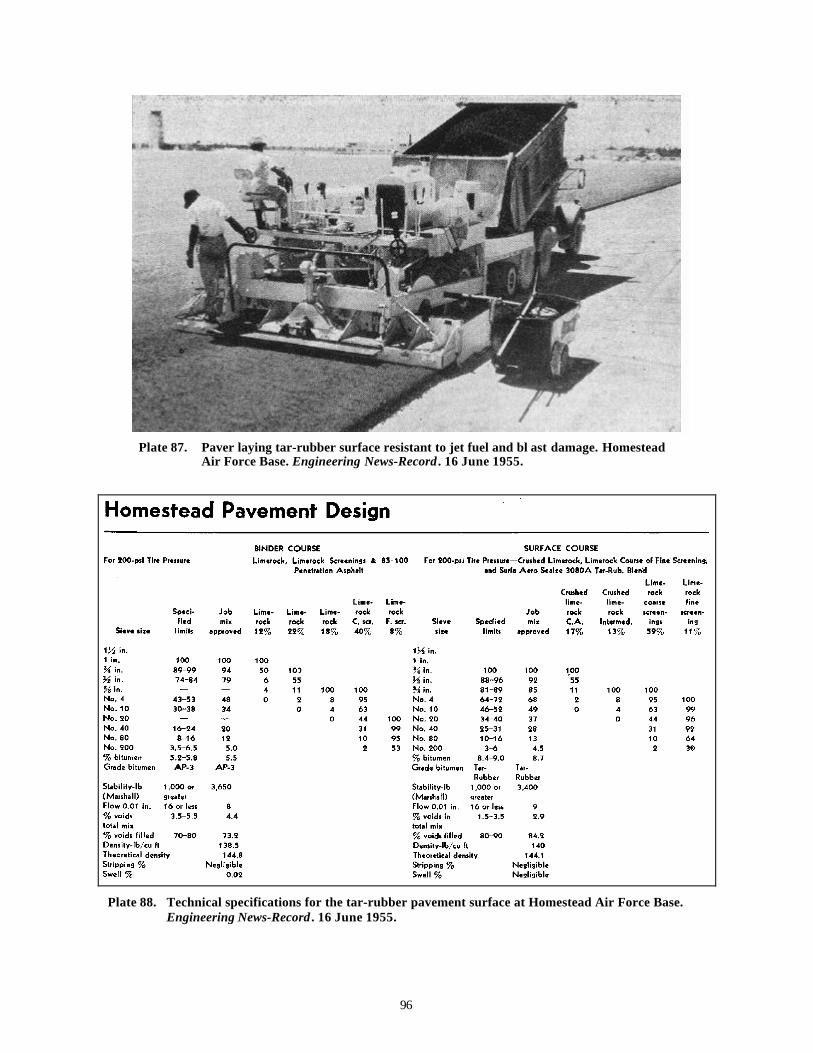
96
Plate 87. Paver laying tar-rubber surface resistant to jet fuel and bl ast damage. HomesteadAir Force Base. Engineering News-Record . 16 June 1955.
Plate 88. Technical specifications for the tar-rubber pavement surface at Homestead Air Force Base.Engineering News-Record . 16 June 1955.
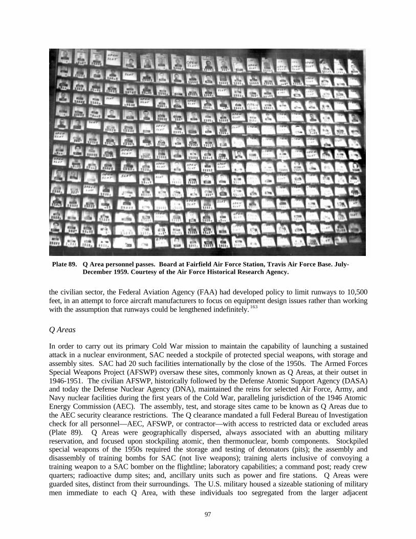
97
Plate 89. Q Area personnel passes. Board at Fairfield Air Force Station, Travis Air Force Base. July-December 1959. Courtesy of the Air Force Historical Research Agency.
the civilian sector, the Federal Aviation Agency (FAA) had developed policy to limit runways to 10,500feet, in an attempt to force aircraft manufacturers to focus on equipment design issues rather than workingwith the assumption that runways could be lengthened indefinitely. 163
Q Areas
In order to carry out its primary Cold War mission to maintain the capability of launching a sustainedattack in a nuclear environment, SAC needed a stockpile of protected special weapons, with storage andassembly sites. SAC had 20 such facilities internationally by the close of the 1950s. The Armed ForcesSpecial Weapons Project (AFSWP) oversaw these sites, commonly known as Q Areas, at their outset in1946-1951. The civilian AFSWP, historically followed by the Defense Atomic Support Agency (DASA)and today the Defense Nuclear Agency (DNA), maintained the reins for selected Air Force, Army, andNavy nuclear facilities during the first years of the Cold War, paralleling jurisdiction of the 1946 AtomicEnergy Commission (AEC). The assembly, test, and storage sites came to be known as Q Areas due tothe AEC security clearance restrictions. The Q clearance mandated a full Federal Bureau of Investigationcheck for all personnel—AEC, AFSWP, or contractor—with access to restricted data or excluded areas(Plate 89). Q Areas were geographically dispersed, always associated with an abutting militaryreservation, and focused upon stockpiling atomic, then thermonuclear, bomb components. Stockpiledspecial weapons of the 1950s required the storage and testing of detonators (pits); the assembly anddisassembly of training bombs for SAC (not live weapons); training alerts inclusive of convoying atraining weapon to a SAC bomber on the flightline; laboratory capabilities; a command post; ready crewquarters; radioactive dump sites; and, ancillary units such as power and fire stations. Q Areas wereguarded sites, distinct from their surroundings. The U.S. military housed a sizeable stationing of militarymen immediate to each Q Area, with these individuals too segregated from the larger adjacent
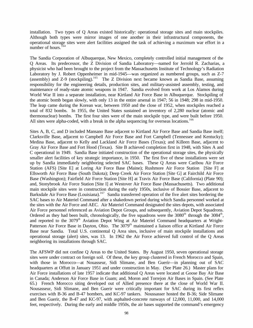
98
installation. Two types of Q Areas existed historically: operational storage sites and main stockpiles.Although both types were mirror images of one another in their infrastructural components, theoperational storage sites were alert facilities assigned the task of achieving a maximum war effort in anumber of hours.164
The Sandia Corporation of Albuquerque, New Mexico, completely controlled initial management of theQ Areas. Its predecessor, the Z Division of Sandia Laboratory—named for Jerrold R. Zacharias, aphysicist who had been brought to the project from the Massachusetts Institute of Technology’s RadiationLaboratory by J. Robert Oppenheimer in mid-1945—was organized as numbered groups, such as Z-7(assembly) and Z-9 (stockpiling).165 The Z Division next became known as Sandia Base, assumingresponsibility for the engineering details, production sites, and military-assisted assembly, testing, andmaintenance of ready-state atomic weapons in 1947. Sandia evolved from work at Los Alamos duringWorld War II into a separate installation, near Kirtland Air Force Base in Albuquerque. Stockpiling ofthe atomic bomb began slowly, with only 13 in the entire arsenal in 1947; 56 in 1948; 298 in mid-1950.The leap came during the Korean war, between 1950 and the close of 1952, when stockpiles reached atotal of 832 bombs. In 1955, the United States sustained an inventory of 2,280 nuclear (atomic andthermonuclear) bombs. The first four sites were of the main stockpile type, and were built before 1950.All sites were alpha-coded, with a break in the alpha sequencing for overseas locations.166
Sites A, B, C, and D included Mansano Base adjacent to Kirtland Air Force Base and Sandia Base itself;Clarksville Base, adjacent to Campbell Air Force Base and Fort Campbell (Tennessee and Kentucky);Medina Base, adjacent to Kelly and Lackland Air Force Bases (Texas); and Killeen Base, adjacent toGray Air Force Base and Fort Hood (Texas). Site B achieved completion first in 1948, with Sites A andC operational in 1949. Sandia Base initiated construction of the operational storage sites, the physicallysmaller alert facilities of key strategic importance, in 1950. The first five of these installations were setup by Sandia immediately neighboring selected SAC bases. These Q Areas were Caribou Air ForceStation (AFS) [Site E] at Loring Air Force Base (Maine); Rushmore Air Force Station [Site F] atEllsworth Air Force Base (South Dakota); Deep Creek Air Force Station [Site G] at Fairchild Air ForceBase (Washington); Fairfield Air Force Station [Site H] at Travis Air Force Base (California) (Plate 90);and, Stonybrook Air Force Station [Site I] at Westover Air Force Base (Massachusetts). Two additionalmain stockpile sites were in construction during the early 1950s, inclusive of Bossier Base, adjacent toBarksdale Air Force Base (Louisiana).167 Sandia transferred operation of the five alert sites bordering theSAC bases to Air Materiel Command after a shakedown period during which Sandia personnel worked atthe sites with the Air Force and AEC. Air Materiel Command designated the sites depots, with associatedAir Force personnel referenced as Aviation Depot Groups, and subsequently, Aviation Depot Squadrons.Ordered as they had been built, chronologically, the five squadrons were the 3080th through the 3084th,and reported to the 3079th Aviation Depot Wing at Air Materiel Command headquarters at Wright-Patterson Air Force Base in Dayton, Ohio. The 3079th maintained a liaison office at Kirtland Air ForceBase near Sandia. Total U.S. continental Q Area sites, inclusive of main stockpile installations andoperational storage (alert) sites, was 13. In 1962 the Air Force achieved full control of the Q Areasneighboring its installations through SAC.
The AFSWP did not confine Q Areas to the United States. By August 1950, seven operational storagesites were under contract on foreign soil. Of these, the key group clustered in French Morocco and Spain,with those in Morocco—at Nouasseur, Sidi Slimane, and Ben Guerir—in planning out of SACheadquarters at Offutt in January 1951 and under construction in May. (See Plate 26.) Master plans forAir Force installations of late 1957 indicate that additional Q Areas were located at Goose Bay Air Basein Canada; Anderson Air Force Base in Guam; and, Moron and Torrejon Air Bases in Spain. (See Plate65.) French Morocco siting developed out of Allied presence there at the close of World War II.Nousasseur, Sidi Slimane, and Ben Guerir were critically important for SAC during its first reflexexercises with B-36 and B-47 bombers, and KC-97 tankers. Noussasser hosted the B-36; Side Slimaneand Ben Guerir, the B-47 and KC-97, with asphalted-concrete runways of 12,000, 11,000, and 14,000feet, respectively. During the early and middle 1950s, the air bases supported the command’s emergency
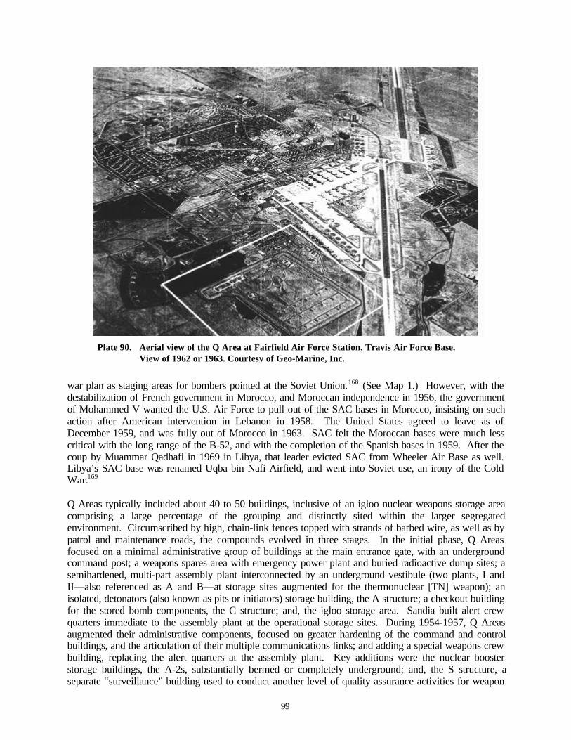
99
Plate 90. Aerial view of the Q Area at Fairfield Air Force Station, Travis Air Force Base.View of 1962 or 1963. Courtesy of Geo-Marine, Inc.
war plan as staging areas for bombers pointed at the Soviet Union.168 (See Map 1.) However, with thedestabilization of French government in Morocco, and Moroccan independence in 1956, the governmentof Mohammed V wanted the U.S. Air Force to pull out of the SAC bases in Morocco, insisting on suchaction after American intervention in Lebanon in 1958. The United States agreed to leave as ofDecember 1959, and was fully out of Morocco in 1963. SAC felt the Moroccan bases were much lesscritical with the long range of the B-52, and with the completion of the Spanish bases in 1959. After thecoup by Muammar Qadhafi in 1969 in Libya, that leader evicted SAC from Wheeler Air Base as well.Libya’s SAC base was renamed Uqba bin Nafi Airfield, and went into Soviet use, an irony of the ColdWar.169
Q Areas typically included about 40 to 50 buildings, inclusive of an igloo nuclear weapons storage areacomprising a large percentage of the grouping and distinctly sited within the larger segregatedenvironment. Circumscribed by high, chain-link fences topped with strands of barbed wire, as well as bypatrol and maintenance roads, the compounds evolved in three stages. In the initial phase, Q Areasfocused on a minimal administrative group of buildings at the main entrance gate, with an undergroundcommand post; a weapons spares area with emergency power plant and buried radioactive dump sites; asemihardened, multi-part assembly plant interconnected by an underground vestibule (two plants, I andII—also referenced as A and B—at storage sites augmented for the thermonuclear [TN] weapon); anisolated, detonators (also known as pits or initiators) storage building, the A structure; a checkout buildingfor the stored bomb components, the C structure; and, the igloo storage area. Sandia built alert crewquarters immediate to the assembly plant at the operational storage sites. During 1954-1957, Q Areasaugmented their administrative components, focused on greater hardening of the command and controlbuildings, and the articulation of their multiple communications links; and adding a special weapons crewbuilding, replacing the alert quarters at the assembly plant. Key additions were the nuclear boosterstorage buildings, the A-2s, substantially bermed or completely underground; and, the S structure, aseparate “surveillance” building used to conduct another level of quality assurance activities for weapon

100
disassembly and maintenance. In 1959-1960, Q Areas expanded their assembly plants to accommodatenew nuclear weapons technologies, also adding laboratory facilities for heavy metals studies at somelocations.
Key buildings within the Q Area were the A and A-2 structures; the C structure; the assembly plants I andII (A and B); the command and control building; and the S structure.170
A Structures
The A and A-2 structures both stored nuclear weapons components, also known as “bird cages.” The Astructure housed atomic bomb detonator pits, while the A-2 structure housed booster capsules for thethermonuclear, or hydrogen, bomb (Plates 91-95). The A-2 structure did not become part of the Q Areauntil the shift toward the TN bomb in 1954. Generally, both structures are referenced as “A” structures.The roles of the A and A-2 structures were parallel. Both were considered hardened structures, with thatof the A-2 additionally shielded by bermed earth or built completely below ground. Identical in design,the A and A-2 structures were built of reinforced concrete, with 10-foot thick walls. For the windowless,aboveground A structure, measuring 41.5 feet by 53 feet (21.5 feet by 33 feet, interior, of nine-footheight), a second story actually provided more protection through its 17 feet of solid reinforced concrete.For the A-2 structure, the storage space for the capsules is entirely bermed or below ground, with a falsesingle story aboveground (again, actually solid reinforced concrete) in the cases where berming wasselected. The interior space is divided into four, single-entry rooms with a narrow bisecting corridorbetween pairs. Each room contained four, six-cubicle; and two, three-cubicle; structural steel Holt rackswelded to special weapons storage standards. One A structure stored 120 detonators, 30 per room. Boththe A and bermed A-2 structures furthermore gave the appearance of office buildings, when viewed fromany distance, through the addition of bands of paired false fenestration and a projecting entrance offset.The bermed A-2 structure was less convincing in this regard from a near perspective, due to the moundedearth and the resultant tunnel-like extension of the offset on one facade. Of curious note, the Q Area Astructure is closely related in its generic appearance to the building housing the first commandheadquarters for SAC at Offutt Air Force Base. That structure, designed in 1941 by architect Albert Kahnfor the Martin Bomber Plant adjacent, contained Curtis LeMay’s office from 1948 into 1957. Whenviewed from the side, the first SAC headquarters also offered a simple rectangular box shape, withbanded fenestration and a corner entrance offset. LeMay’s early headquarters was known as the ABuilding—a continuance from its designation during the Martin bomber days171 (Plates 96-97).
Plate 91. Black & Veatch. A Structure in the Q Area at Barksdale Air Force Base. Viewof 1995. Courtesy of Mariah Associates, Inc.
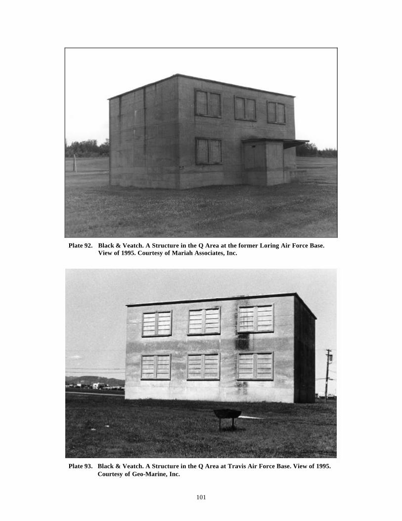
101
Plate 92. Black & Veatch. A Structure in the Q Area at the former Loring Air Force Base.View of 1995. Courtesy of Mariah Associates, Inc.
Plate 93. Black & Veatch. A Structure in the Q Area at Travis Air Force Base. View of 1995.Courtesy of Geo-Marine, Inc.
102
Plate 94. Black & Veatch. A-1 Structure in the Q Area at the former Loring Air Force Base.Entrance view, 1995. Courtesy of Mariah Associates, Inc.
Plate 95. Black & Veatch. A-1 Structure in the Q Area at the former Loring Air Force Base.Rear corner view, 1995. Courtesy of Mariah Associates, Inc.

103
Plate 96. Albert Kahn. A Building of the MartinBomber Plant (1941). SAC CommandHeadquarters, 1948-1957. View of July 1999.Photograph, K.J. Weitze.
Plate 97. Oblique view of the A Building (first SAC Command Headquarters). View ofJuly 1999. Photograph, K.J. Weitze.
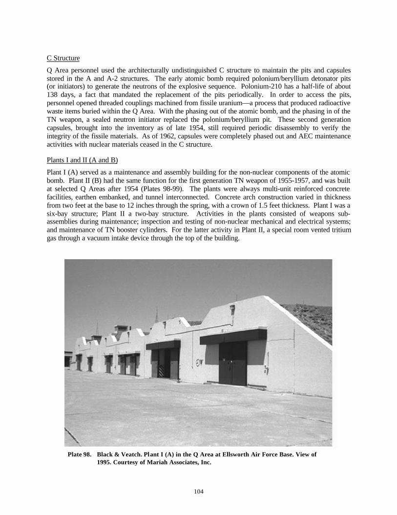
104
C Structure
Q Area personnel used the architecturally undistinguished C structure to maintain the pits and capsulesstored in the A and A-2 structures. The early atomic bomb required polonium/beryllium detonator pits(or initiators) to generate the neutrons of the explosive sequence. Polonium-210 has a half-life of about138 days, a fact that mandated the replacement of the pits periodically. In order to access the pits,personnel opened threaded couplings machined from fissile uranium—a process that produced radioactivewaste items buried within the Q Area. With the phasing out of the atomic bomb, and the phasing in of theTN weapon, a sealed neutron initiator replaced the polonium/beryllium pit. These second generationcapsules, brought into the inventory as of late 1954, still required periodic disassembly to verify theintegrity of the fissile materials. As of 1962, capsules were completely phased out and AEC maintenanceactivities with nuclear materials ceased in the C structure.
Plants I and II (A and B)
Plant I (A) served as a maintenance and assembly building for the non-nuclear components of the atomicbomb. Plant II (B) had the same function for the first generation TN weapon of 1955-1957, and was builtat selected Q Areas after 1954 (Plates 98-99). The plants were always multi-unit reinforced concretefacilities, earthen embanked, and tunnel interconnected. Concrete arch construction varied in thicknessfrom two feet at the base to 12 inches through the spring, with a crown of 1.5 feet thickness. Plant I was asix-bay structure; Plant II a two-bay structure. Activities in the plants consisted of weapons sub-assemblies during maintenance; inspection and testing of non-nuclear mechanical and electrical systems;and maintenance of TN booster cylinders. For the latter activity in Plant II, a special room vented tritiumgas through a vacuum intake device through the top of the building.
Plate 98. Black & Veatch. Plant I (A) in the Q Area at Ellsworth Air Force Base. View of1995. Courtesy of Mariah Associates, Inc.
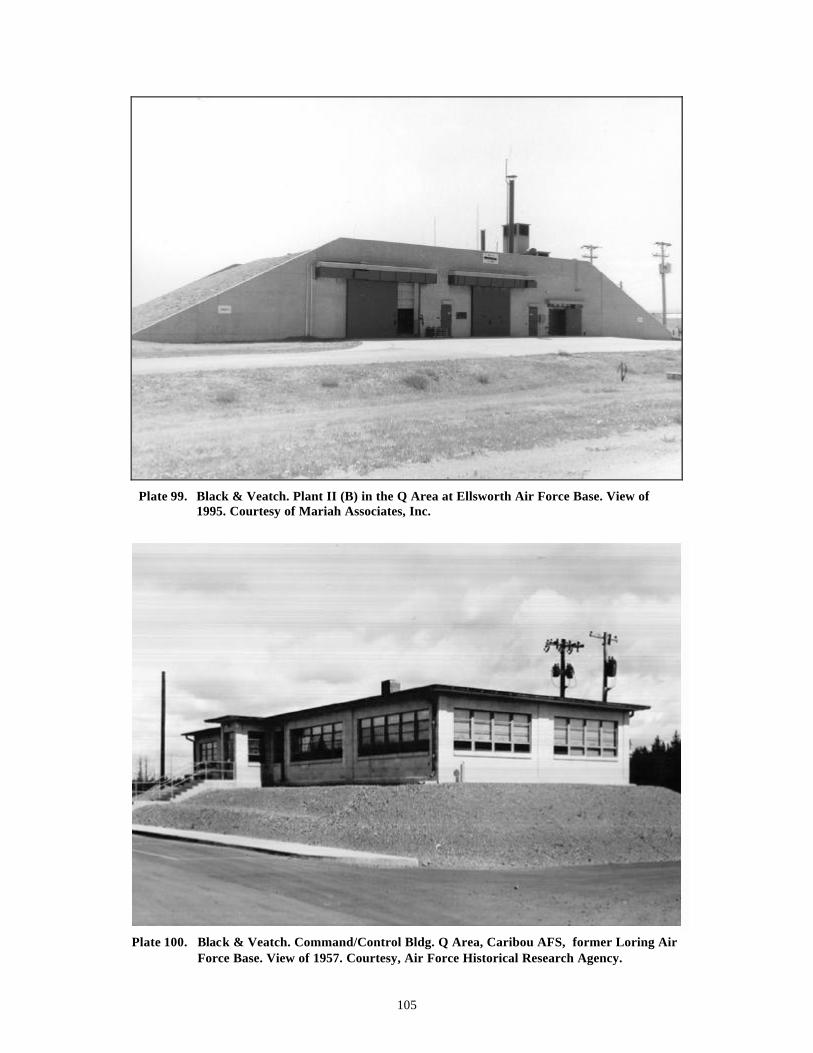
105
Plate 99. Black & Veatch. Plant II (B) in the Q Area at Ellsworth Air Force Base. View of1995. Courtesy of Mariah Associates, Inc.
Plate 100. Black & Veatch. Command/Control Bldg. Q Area, Caribou AFS, former Loring AirForce Base. View of 1957. Courtesy, Air Force Historical Research Agency.
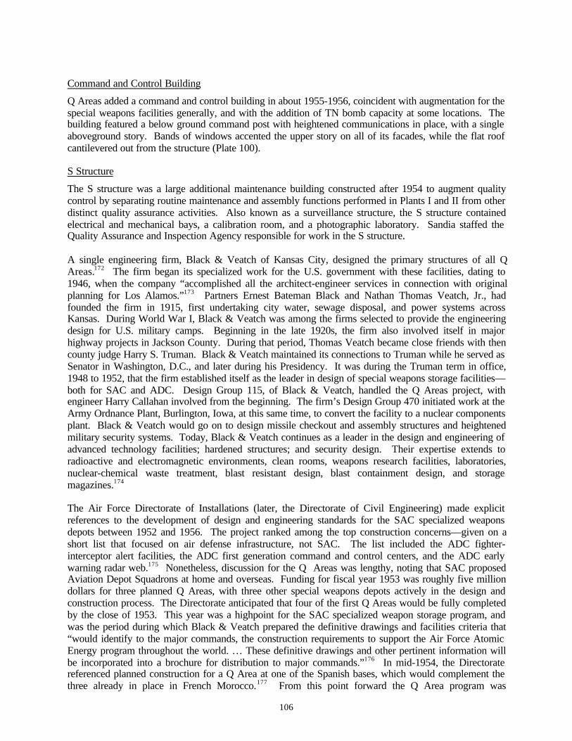
106
Command and Control Building
Q Areas added a command and control building in about 1955-1956, coincident with augmentation for thespecial weapons facilities generally, and with the addition of TN bomb capacity at some locations. Thebuilding featured a below ground command post with heightened communications in place, with a singleaboveground story. Bands of windows accented the upper story on all of its facades, while the flat roofcantilevered out from the structure (Plate 100).
S Structure
The S structure was a large additional maintenance building constructed after 1954 to augment qualitycontrol by separating routine maintenance and assembly functions performed in Plants I and II from otherdistinct quality assurance activities. Also known as a surveillance structure, the S structure containedelectrical and mechanical bays, a calibration room, and a photographic laboratory. Sandia staffed theQuality Assurance and Inspection Agency responsible for work in the S structure.
A single engineering firm, Black & Veatch of Kansas City, designed the primary structures of all QAreas.172 The firm began its specialized work for the U.S. government with these facilities, dating to1946, when the company “accomplished all the architect-engineer services in connection with originalplanning for Los Alamos.”173 Partners Ernest Bateman Black and Nathan Thomas Veatch, Jr., hadfounded the firm in 1915, first undertaking city water, sewage disposal, and power systems acrossKansas. During World War I, Black & Veatch was among the firms selected to provide the engineeringdesign for U.S. military camps. Beginning in the late 1920s, the firm also involved itself in majorhighway projects in Jackson County. During that period, Thomas Veatch became close friends with thencounty judge Harry S. Truman. Black & Veatch maintained its connections to Truman while he served asSenator in Washington, D.C., and later during his Presidency. It was during the Truman term in office,1948 to 1952, that the firm established itself as the leader in design of special weapons storage facilities—both for SAC and ADC. Design Group 115, of Black & Veatch, handled the Q Areas project, withengineer Harry Callahan involved from the beginning. The firm’s Design Group 470 initiated work at theArmy Ordnance Plant, Burlington, Iowa, at this same time, to convert the facility to a nuclear componentsplant. Black & Veatch would go on to design missile checkout and assembly structures and heightenedmilitary security systems. Today, Black & Veatch continues as a leader in the design and engineering ofadvanced technology facilities; hardened structures; and security design. Their expertise extends toradioactive and electromagnetic environments, clean rooms, weapons research facilities, laboratories,nuclear-chemical waste treatment, blast resistant design, blast containment design, and storagemagazines.174
The Air Force Directorate of Installations (later, the Directorate of Civil Engineering) made explicitreferences to the development of design and engineering standards for the SAC specialized weaponsdepots between 1952 and 1956. The project ranked among the top construction concerns—given on ashort list that focused on air defense infrastructure, not SAC. The list included the ADC fighter-interceptor alert facilities, the ADC first generation command and control centers, and the ADC earlywarning radar web.175 Nonetheless, discussion for the Q Areas was lengthy, noting that SAC proposedAviation Depot Squadrons at home and overseas. Funding for fiscal year 1953 was roughly five milliondollars for three planned Q Areas, with three other special weapons depots actively in the design andconstruction process. The Directorate anticipated that four of the first Q Areas would be fully completedby the close of 1953. This year was a highpoint for the SAC specialized weapon storage program, andwas the period during which Black & Veatch prepared the definitive drawings and facilities criteria that“would identify to the major commands, the construction requirements to support the Air Force AtomicEnergy program throughout the world. … These definitive drawings and other pertinent information willbe incorporated into a brochure for distribution to major commands.”176 In mid-1954, the Directoratereferenced planned construction for a Q Area at one of the Spanish bases, which would complement thethree already in place in French Morocco.177 From this point forward the Q Area program was
107
approaching buildout, and SAC sought approval for its specialized weapons storage as “standard.” Theupcoming shift marked the transition from engineering and construction, to full scale special weaponsreceipt and day-to-day operations at the storage sites.
In late summer of 1954 Air Force headquarters prepared to submit a written plan of the comprehensiveSAC special weapons storage facilities—siting and operations—to the Joint Chiefs of Staff, followed bySecretary of Defense and Presidential review. The Air Force then met with Black & Veatch in KansasCity in August. The next month, the Directorate of Construction within the office of the Assistant Chiefof Staff, Installations, produced the formal schedule for a second-tier SAC program of special weaponsstorage design and construction, estimated dates of completion, and beneficial occupancy dates. InOctober formal guidance was ready for distribution to the appropriate SAC bases. During the remainingmonths of 1954, the Air Force held meetings with Black & Veatch, amended original guidance, andreceived Presidential approval.178 In early 1955, the Armed Services and Appropriations Committeesgave this SAC special weapons storage program the necessary clearances, with the Secretary of Defense,the Joint Chiefs of Staff, and the AFSWP staff produced and received memoranda discussing the“responsibilities for the provision of Zone of Interior atomic weapon storage facilities.” The AFSWP hadthe role of approving “site and building plans for each location in the program.” Agencies in charge wereto approve SAC base locations as accepted for the special storage sites at four per month.179 As of theclose of 1956, 15 of the Q Areas were considered fully complete and approved, with the remaining five QAreas anticipated to achieve the same status by June 1957.180
SAC’s planned use of the atomic bomb, and later TN weapon, hinged on its bomber force and their accessto the Q Areas. While the Cold War was gearing up during the 1948-1953 years, SAC had B-36s (as oflate 1948) and B-47s (as of late 1951) in its inventory. The B-36 could carry the atomic bomb and thevery large, first generation TN weapon; the B-47 could not. After the middle 1950s, large yield TNdevices compatible with the B-47 were developed. Before 1954, SAC B-36s were required to fly to oneof the main storage Q Areas from their home base to receive their bombs, then proceeding on either ahypothetical strike mission or deploying to a forward base—such as those in French Morocco—fromwhich they were posed to launch a strike mission. This first method of coordinating the bombers with thebombs was cumbersome and slow, and meant that SAC could not penetrate the Soviet early warning radarnet in a mass strike in under 36 hours. Not until 1954 did several bases with operational special weaponsstorage sites (alert Q Areas) began receiving atomic bombs. And not until 1956 were atomic bombs inplace at all five of the alert Q Areas neighboring Ellsworth, Fairchild, Loring, Travis, and Westover AirForce Bases.181 It was no coincidence that these five bases also each had large percentages of the total B-36 SAC inventory and the only clusters of the first generation Luria B-36 wing hangar. In selectinstances, bomber infrastructure supported a specialized mission directly related to an adjacent Q Area,rather than to a wing of B-36s. At Kirtland Air Force Base, neighboring Sandia and the main storage siteof Mansano Base, SAC conducted atomic bomb and TN weapon handling courses for crews of the B-36,and subsequently B-47 from 1953 to late 1955.182 Kirtland supported three double-cantilever hangars—one prototypical medium bomber hangar (and likely the first built in the nation), and two standardmedium bomber hangars. By 1957, SAC had the infrastructure, weapons, and organization to “use bothatomic and thermonuclear weapons on a mass scale,” honed through “major atomic exercises.”183 TheSAC mission was a fully integrated one.
Alert Apron Configurations and Crew Quarters
By the early 1950s, SAC was planning for an all-jet, intercontinental bomber, the B-52, and anaccompanying all-jet refueling tanker, the KC-135. SAC took delivery of its first B-52 in June 1955.Castle Air Force Base was SAC’s first B-52 base, with the installation receiving aircraft in 1956. Loringand Westover also began to receive B-52s before the close of the year. As 1957 opened 88 B-52s werelocated at SAC bases, while 17 more were in test programs or being modernized at the Wichita Boeingplant. The KC-135 production ran slightly behind that of the B-52, with its initial flight in August
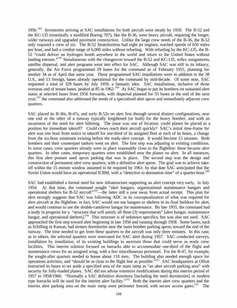
108
1956. 184 Inventories arriving at SAC installations for both aircraft were steady by 1959. The B-52 andthe KC-135 (essentially a modified Boeing 707), like the B-36, were heavy aircraft, requiring the longer,wider runways and upgraded pavement construction. Unlike the large crew needs of the B-36, the B-52only required a crew of six. The B-52 Stratofortress had eight jet engines, reached speeds of 650 milesper hour, and had a combat range of 6,000 miles without refueling. With refueling by the KC-135, the B-52 “could deliver an hydrogen bomb anywhere in the world and return to the United States withoutlanding enroute.”185 Simultaneous with the changeover toward the B-52 and KC-135, reflex assignments,satellite dispersal, and alert programs went into effect for SAC. Although SAC was still in its infancy,generally, the Air Force programmed 29 bases for the command as of February 1955, planning foranother 34 as of April that same year. These programmed SAC installations were in addition to the 38U.S., and 13 foreign, bases already operational for the command by mid-decade. Of some note, SACrequested a total of 329 bases by July 1959, a fantastic idea. SAC installations, inclusive of thoseoverseas and of tenant bases, peaked at 85 in 1962.186 As SAC began to put its bombers on sustained alertstatus at selected bases from 1956 forwards, with dispersal planned for 55 bases at the end of the nextyear,187 the command also addressed the needs of a specialized alert apron and immediately adjacent crewquarters.
SAC placed its B-36s, B-47s, and early B-52s on alert first through several distinct configurations, nearone end or the other of a runway typically lengthened (or built) for the heavy bomber, and with anawareness of the need for alert billeting. The issue was one of location: could planes be placed in aposition for immediate takeoff? Could crews reach their aircraft quickly? SAC’s initial time-frame foralert was one hour from notice to takeoff for one-third of its assigned fleet at each of its bases, a changefrom the six-hour minimum existing before the ready-alert concept. It would become 15 minutes. Bothbombers and their counterpart tankers went on alert. The first step was adjusting to existing conditions.In some cases, crew quarters already were in place reasonably close to the flightline: these became alertquarters. In other cases, temporary quarters were established near the planes on alert. In all instances,this first alert posture used apron parking that was in place. The second step was the design andconstruction of permanent alert crew quarters, with a definitive alert apron. The goal was to achieve take-off within the 15 minute window assumed to be required by 1961: by that date SAC anticipated that theSoviet Union would have an operational ICBM, with a “detection to detonation time” of a quarter-hour.188
SAC had established a formal need for new infrastructure supporting an alert concept very early, in July1954. At that time, the command sought “alert hangars, organizational maintenance hangars andoperational shelters for B-52 aircraft”189—the latter still a year away from actual receipt. This plan foralert strongly suggests that SAC was following ADC in its conceptualization of what was required foralert aircraft at the flightline: in fact, SAC would not use hangars or shelters in its final buildout for alert,and would continue to use the double-cantilever hangar for maintenance. By late 1955, the command hada study in progress for a “structure that will satisfy all three (3) requirements” [alert hangar, maintenancehangar, and operational shelters].190 This structure is of unknown specifics, but was also not used. SACapproached the first step toward alert beginning in late 1956 and running through 1958. Some bases, suchas Schilling in Kansas, had airmen dormitories near the main bomber parking apron, toward the end of therunway. The time needed to get from these quarters to the aircraft was only three minutes. In this case,as in others, the selected quarters were renovated for SAC alert during 1957. SAC conducted surveys,installation by installation, of its existing buildings to ascertain those that could serve as ready crewfacilities. This interim solution focused on barracks able to accommodate one-third of the flight andmaintenance crews for an assigned wing, with a few miscellaneous personnel. For the B-47, for example,the sought-after quarters needed to house about 110 men. The building also needed enough space foroperations activities, and “should be as close to the flight line as possible.”191 SAC headquarters at Offuttinstructed its bases to set aside a specified area of the main ramp as “an alert aircraft parking area” withsecurity for fully-loaded planes. SAC did not advise extensive modifications during this interim period of1957 to 1958/1960. “Normally a SAC definitive dormitory [including the steel dormitories] or moderntype barracks will be used for the interim alert facility.”192 Both the interim alert crew quarters and theinterim alert parking area on the main ramp were perimeter fenced, with secure access gates.193 The
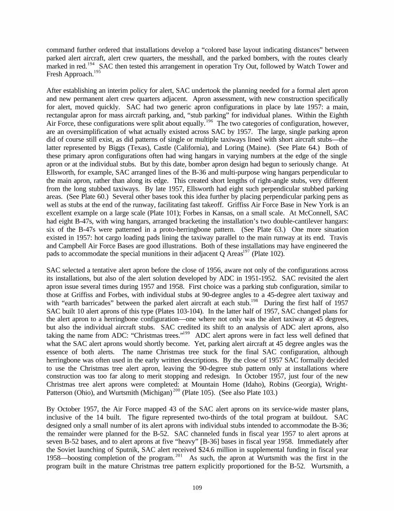
109
command further ordered that installations develop a “colored base layout indicating distances” betweenparked alert aircraft, alert crew quarters, the messhall, and the parked bombers, with the routes clearlymarked in red.194 SAC then tested this arrangement in operation Try Out, followed by Watch Tower andFresh Approach.195
After establishing an interim policy for alert, SAC undertook the planning needed for a formal alert apronand new permanent alert crew quarters adjacent. Apron assessment, with new construction specificallyfor alert, moved quickly. SAC had two generic apron configurations in place by late 1957: a main,rectangular apron for mass aircraft parking, and, “stub parking” for individual planes. Within the EighthAir Force, these configurations were split about equally.196 The two categories of configuration, however,are an oversimplification of what actually existed across SAC by 1957. The large, single parking aprondid of course still exist, as did patterns of single or multiple taxiways lined with short aircraft stubs—thelatter represented by Biggs (Texas), Castle (California), and Loring (Maine). (See Plate 64.) Both ofthese primary apron configurations often had wing hangars in varying numbers at the edge of the singleapron or at the individual stubs. But by this date, bomber apron design had begun to seriously change. AtEllsworth, for example, SAC arranged lines of the B-36 and multi-purpose wing hangars perpendicular tothe main apron, rather than along its edge. This created short lengths of right-angle stubs, very differentfrom the long stubbed taxiways. By late 1957, Ellsworth had eight such perpendicular stubbed parkingareas. (See Plate 60.) Several other bases took this idea further by placing perpendicular parking pens aswell as stubs at the end of the runway, facilitating fast takeoff. Griffiss Air Force Base in New York is anexcellent example on a large scale (Plate 101); Forbes in Kansas, on a small scale. At McConnell, SAChad eight B-47s, with wing hangars, arranged bracketing the installation’s two double-cantilever hangars:six of the B-47s were patterned in a proto-herringbone pattern. (See Plate 63.) One more situationexisted in 1957: hot cargo loading pads lining the taxiway parallel to the main runway at its end. Travisand Campbell Air Force Bases are good illustrations. Both of these installations may have engineered thepads to accommodate the special munitions in their adjacent Q Areas197 (Plate 102).
SAC selected a tentative alert apron before the close of 1956, aware not only of the configurations acrossits installations, but also of the alert solution developed by ADC in 1951-1952. SAC revisited the alertapron issue several times during 1957 and 1958. First choice was a parking stub configuration, similar tothose at Griffiss and Forbes, with individual stubs at 90-degree angles to a 45-degree alert taxiway andwith “earth barricades” between the parked alert aircraft at each stub.198 During the first half of 1957SAC built 10 alert aprons of this type (Plates 103-104). In the latter half of 1957, SAC changed plans forthe alert apron to a herringbone configuration—one where not only was the alert taxiway at 45 degrees,but also the individual aircraft stubs. SAC credited its shift to an analysis of ADC alert aprons, alsotaking the name from ADC: “Christmas trees.”199 ADC alert aprons were in fact less well defined thatwhat the SAC alert aprons would shortly become. Yet, parking alert aircraft at 45 degree angles was theessence of both alerts. The name Christmas tree stuck for the final SAC configuration, althoughherringbone was often used in the early written descriptions. By the close of 1957 SAC formally decidedto use the Christmas tree alert apron, leaving the 90-degree stub pattern only at installations whereconstruction was too far along to merit stopping and redesign. In October 1957, just four of the newChristmas tree alert aprons were completed: at Mountain Home (Idaho), Robins (Georgia), Wright-Patterson (Ohio), and Wurtsmith (Michigan) 200 (Plate 105). (See also Plate 103.)
By October 1957, the Air Force mapped 43 of the SAC alert aprons on its service-wide master plans,inclusive of the 14 built. The figure represented two-thirds of the total program at buildout. SACdesigned only a small number of its alert aprons with individual stubs intended to accommodate the B-36;the remainder were planned for the B-52. SAC channeled funds in fiscal year 1957 to alert aprons atseven B-52 bases, and to alert aprons at five “heavy” [B-36] bases in fiscal year 1958. Immediately afterthe Soviet launching of Sputnik, SAC alert received $24.6 million in supplemental funding in fiscal year1958—boosting completion of the program. 201 As such, the apron at Wurtsmith was the first in theprogram built in the mature Christmas tree pattern explicitly proportioned for the B-52. Wurtsmith, a

110
Pla
te 1
01.
SAC
rec
tang
ular
stu
bbed
par
king
apr
ons
and
angl
ed a
lert
tax
iway
, wit
h w
ing
hang
ars
built
and
pla
nned
(m
idgr
ound
rig
ht).
Gri
ffis
s A
ir
For
ce B
ase.
Dir
ecto
rate
of
Inst
alla
tion
s. M
aste
r P
lan
of O
ctob
er 1
957.
Col
lect
ion
of K
.J. W
eitz
e.
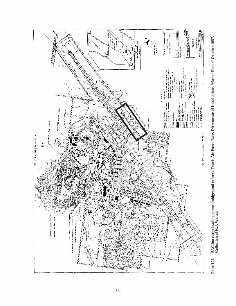
111
Pla
te 1
02.
SAC
hot
car
go lo
adin
g ap
ron
(mid
grou
nd c
ente
r). T
ravi
s A
ir F
orce
Bas
e. D
irec
tora
te o
f In
stal
lati
ons.
Mas
ter
Pla
n of
Oct
ober
195
7.
Col
lect
ion
of K
.J. W
eitz
e.
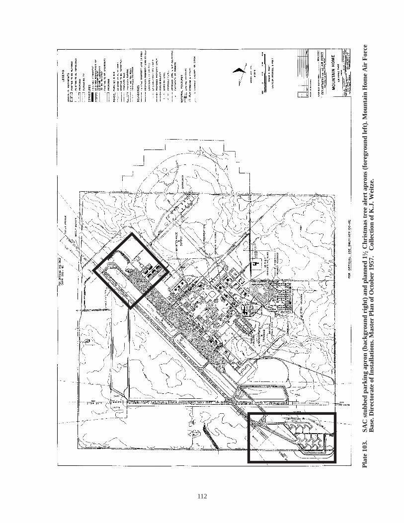
Pla
te 1
03.
SAC
stu
bbed
par
king
apr
on (
back
grou
nd r
ight
) an
d pl
anne
d 11
2 C
hris
tmas
tre
e al
ert
apro
ns (
fore
grou
nd le
ft).
Mou
ntai
n H
ome
Air
For
ce
Bas
e. D
irec
tora
te o
f Ins
talla
tion
s. M
aste
r P
lan
of O
ctob
er 1
957.
C
olle
ctio
n of
K.J
. Wei
tze.
112
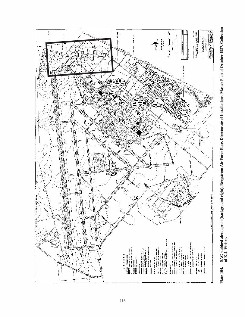
113
Pla
te 1
04.
SAC
stu
bbed
ale
rt a
pron
(bac
kgro
und
righ
t). B
ergs
trom
Air
For
ce B
ase.
Dir
ecto
rate
of I
nsta
llati
ons.
Mas
ter
Pla
n of
Oct
ober
195
7. C
olle
ctio
n of
K.J
. Wei
tze.

114
Pla
te 1
05.
SAC
Chr
istm
as t
ree
aler
t ap
ron,
bac
kgro
und
cent
er. P
roto
-ale
rt s
tubb
ed a
pron
and
tan
ker
pen,
cen
ter.
Wur
tsm
ith
Air
For
ce B
ase.
D
irec
tora
te o
f In
stal
lati
ons.
Mas
ter
Pla
n of
Oct
ober
195
7. C
olle
ctio
n of
K.J
. Wei
tze.
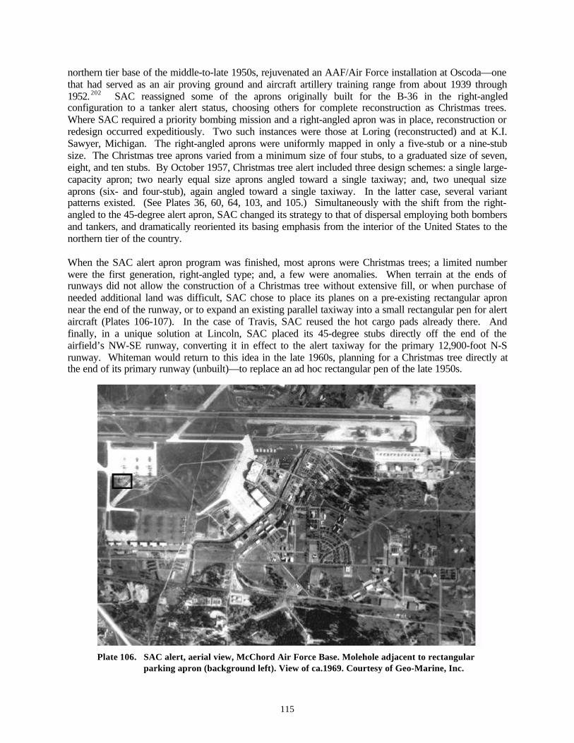
115
northern tier base of the middle-to-late 1950s, rejuvenated an AAF/Air Force installation at Oscoda—onethat had served as an air proving ground and aircraft artillery training range from about 1939 through1952. 202 SAC reassigned some of the aprons originally built for the B-36 in the right-angledconfiguration to a tanker alert status, choosing others for complete reconstruction as Christmas trees.Where SAC required a priority bombing mission and a right-angled apron was in place, reconstruction orredesign occurred expeditiously. Two such instances were those at Loring (reconstructed) and at K.I.Sawyer, Michigan. The right-angled aprons were uniformly mapped in only a five-stub or a nine-stubsize. The Christmas tree aprons varied from a minimum size of four stubs, to a graduated size of seven,eight, and ten stubs. By October 1957, Christmas tree alert included three design schemes: a single large-capacity apron; two nearly equal size aprons angled toward a single taxiway; and, two unequal sizeaprons (six- and four-stub), again angled toward a single taxiway. In the latter case, several variantpatterns existed. (See Plates 36, 60, 64, 103, and 105.) Simultaneously with the shift from the right-angled to the 45-degree alert apron, SAC changed its strategy to that of dispersal employing both bombersand tankers, and dramatically reoriented its basing emphasis from the interior of the United States to thenorthern tier of the country.
When the SAC alert apron program was finished, most aprons were Christmas trees; a limited numberwere the first generation, right-angled type; and, a few were anomalies. When terrain at the ends ofrunways did not allow the construction of a Christmas tree without extensive fill, or when purchase ofneeded additional land was difficult, SAC chose to place its planes on a pre-existing rectangular apronnear the end of the runway, or to expand an existing parallel taxiway into a small rectangular pen for alertaircraft (Plates 106-107). In the case of Travis, SAC reused the hot cargo pads already there. Andfinally, in a unique solution at Lincoln, SAC placed its 45-degree stubs directly off the end of theairfield’s NW-SE runway, converting it in effect to the alert taxiway for the primary 12,900-foot N-Srunway. Whiteman would return to this idea in the late 1960s, planning for a Christmas tree directly atthe end of its primary runway (unbuilt)—to replace an ad hoc rectangular pen of the late 1950s.
Plate 106. SAC alert, aerial view, McChord Air Force Base. Molehole adjacent to rectangularparking apron (background left). View of ca.1969. Courtesy of Geo-Marine, Inc.

116
Plate 107. SAC alert, aerial view, Whiteman Air Force Base. Molehole adjacent to long rectangular apron(center right). 1959. Courtesy of Whiteman Air Force Base.
In late 1957 none of the existing alert aprons in any configuration included permanent crew quarters.Individual installations followed the orders from SAC headquarters and adapted barracks and dormitoriesnear the flightline where possible, but this was soon found to be expensive. The Second Air Forceinfluenced the form that a second interim solution would take, with its commander asserting thatcommercial house trailers were the answer to a ready-made, moveable, interim alert housing. InDecember 1957, the Second Air Force’s commander, General J.P. McConnell, requested and receivedpermission to purchase four commercial house trailers for testing by the 301st Bomb Wing. McConnellmaintained that the trailers “could be moved to either end of the runway in case wind changes required achange in the takeoff direction, and if the dispersal plan was expanded, … could be readily moved toother bases.”203 SAC tested these units during the first months of 1958 at Barksdale Air Force Base inLouisiana. SAC commissioned formal trailer production by the Travelite Trailer Company of Fort Worth,Texas, in the latter half of 1958, with 56, 50-foot trailers manufactured and delivered to the Air Force at acost of $336,000. SAC shipped these facilities in multiples to Carswell (Texas) [five]; Chennault(Louisiana) [two]; Hunter (Georgia) [five]; Lincoln (Nebraska) [five]; MacDill (Florida) [seven];Westover (Massachusetts) [six]; and Whiteman (Missouri) [three]. SAC shipped the remaining 23 trailersto overseas bases. All trailers left the Fort Worth plant before the end of December 1958.204 During1959, SAC bought a fleet of alert vehicles, both station wagons (539) and panel trucks (93), to transportairmen to and from alert duty (Plate 108).
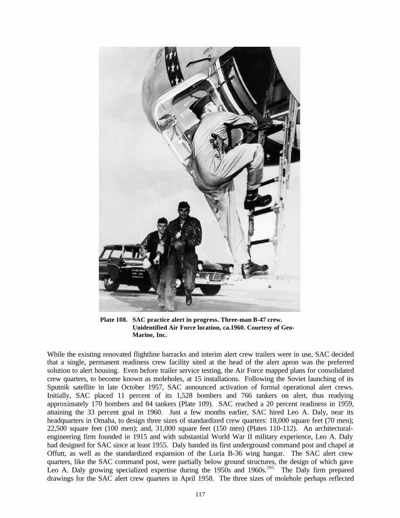
117
Plate 108. SAC practice alert in progress. Three-man B-47 crew.Unidentified Air Force location, ca.1960. Courtesy of Geo-Marine, Inc.
While the existing renovated flightline barracks and interim alert crew trailers were in use, SAC decidedthat a single, permanent readiness crew facility sited at the head of the alert apron was the preferredsolution to alert housing. Even before trailer service testing, the Air Force mapped plans for consolidatedcrew quarters, to become known as moleholes, at 15 installations. Following the Soviet launching of itsSputnik satellite in late October 1957, SAC announced activation of formal operational alert crews.Initially, SAC placed 11 percent of its 1,528 bombers and 766 tankers on alert, thus readyingapproximately 170 bombers and 84 tankers (Plate 109). SAC reached a 20 percent readiness in 1959,attaining the 33 percent goal in 1960. Just a few months earlier, SAC hired Leo A. Daly, near itsheadquarters in Omaha, to design three sizes of standardized crew quarters: 18,000 square feet (70 men);22,500 square feet (100 men); and, 31,000 square feet (150 men) (Plates 110-112). An architectural-engineering firm founded in 1915 and with substantial World War II military experience, Leo A. Dalyhad designed for SAC since at least 1955. Daly handed its first underground command post and chapel atOffutt, as well as the standardized expansion of the Luria B-36 wing hangar. The SAC alert crewquarters, like the SAC command post, were partially below ground structures, the design of which gaveLeo A. Daly growing specialized expertise during the 1950s and 1960s.205 The Daly firm prepareddrawings for the SAC alert crew quarters in April 1958. The three sizes of molehole perhaps reflected
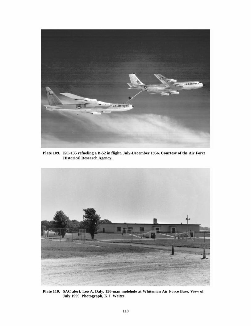
118
Plate 109. KC-135 refueling a B-52 in flight. July-December 1956. Courtesy of the Air ForceHistorical Research Agency.
Plate 110. SAC alert. Leo A. Daly. 150-man molehole at Whiteman Air Force Base. View ofJuly 1999. Photograph, K.J. Weitze.

119
Plate 111. SAC alert. Leo A. Daly. 70-man molehole at the former Schilling Air Force Base.View of July 1999. Photograph, K.J. Weitze.
Plate 112. SAC alert. Leo A. Daly. 70-man molehole at the former Castle Air Force Base.View of December 1998. Photograph, K.J. Weitze.
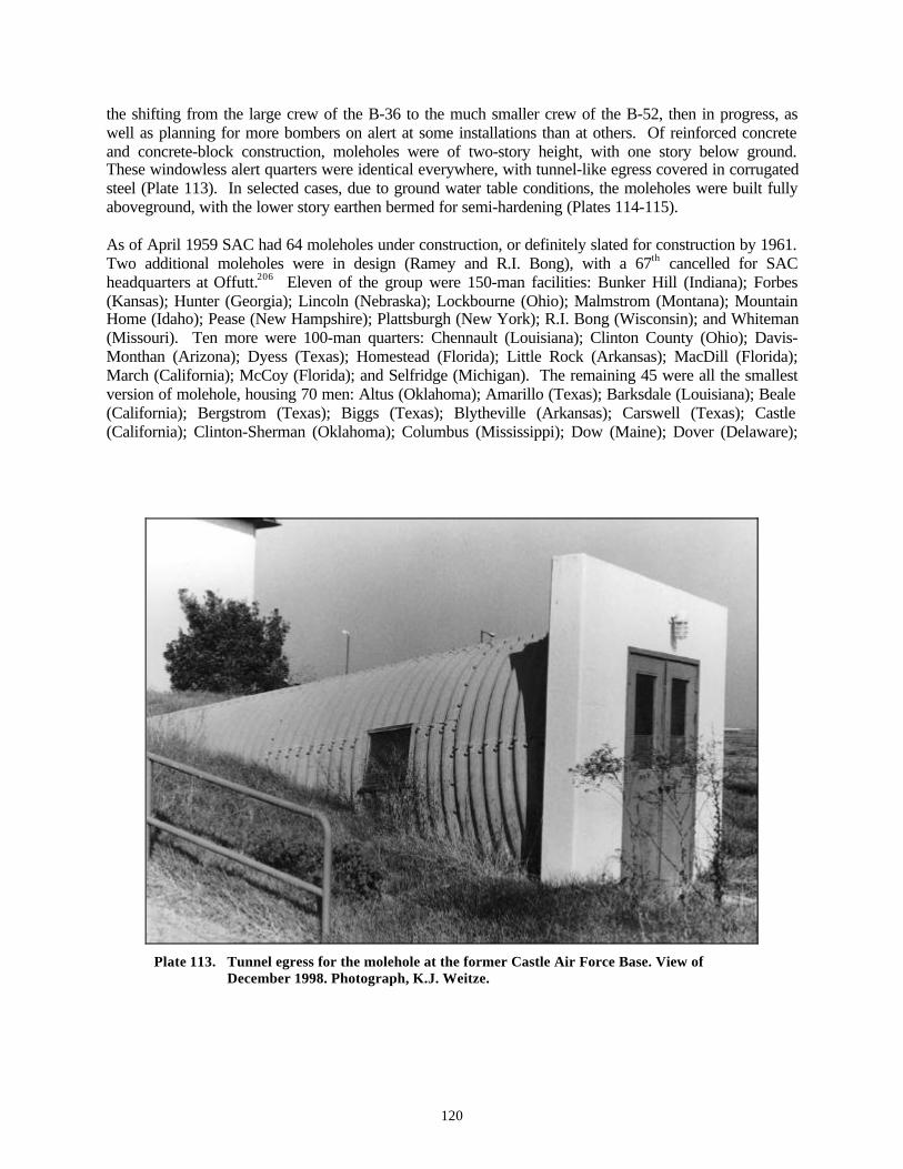
120
the shifting from the large crew of the B-36 to the much smaller crew of the B-52, then in progress, aswell as planning for more bombers on alert at some installations than at others. Of reinforced concreteand concrete-block construction, moleholes were of two-story height, with one story below ground.These windowless alert quarters were identical everywhere, with tunnel-like egress covered in corrugatedsteel (Plate 113). In selected cases, due to ground water table conditions, the moleholes were built fullyaboveground, with the lower story earthen bermed for semi-hardening (Plates 114-115).
As of April 1959 SAC had 64 moleholes under construction, or definitely slated for construction by 1961.Two additional moleholes were in design (Ramey and R.I. Bong), with a 67th cancelled for SACheadquarters at Offutt.206 Eleven of the group were 150-man facilities: Bunker Hill (Indiana); Forbes(Kansas); Hunter (Georgia); Lincoln (Nebraska); Lockbourne (Ohio); Malmstrom (Montana); MountainHome (Idaho); Pease (New Hampshire); Plattsburgh (New York); R.I. Bong (Wisconsin); and Whiteman(Missouri). Ten more were 100-man quarters: Chennault (Louisiana); Clinton County (Ohio); Davis-Monthan (Arizona); Dyess (Texas); Homestead (Florida); Little Rock (Arkansas); MacDill (Florida);March (California); McCoy (Florida); and Selfridge (Michigan). The remaining 45 were all the smallestversion of molehole, housing 70 men: Altus (Oklahoma); Amarillo (Texas); Barksdale (Louisiana); Beale(California); Bergstrom (Texas); Biggs (Texas); Blytheville (Arkansas); Carswell (Texas); Castle(California); Clinton-Sherman (Oklahoma); Columbus (Mississippi); Dow (Maine); Dover (Delaware);
Plate 113. Tunnel egress for the molehole at the former Castle Air Force Base. View ofDecember 1998. Photograph, K.J. Weitze.

121
Plate 114. SAC alert. Leo A. Daly. 100-man molehole at the former Homestead Air Force Base.Built aboveground: bermed. View of 1995. Courtesy of Mariah Associates, Inc.
Plate 115. SAC alert. Oblique view of berming for the molehole at the former Homestead AirForce Base, 1995. Courtesy of Mariah Associates, Inc.
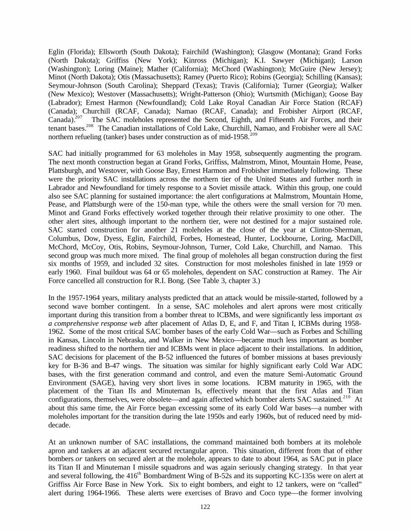
122
Eglin (Florida); Ellsworth (South Dakota); Fairchild (Washington); Glasgow (Montana); Grand Forks(North Dakota); Griffiss (New York); Kinross (Michigan); K.I. Sawyer (Michigan); Larson(Washington); Loring (Maine); Mather (California); McChord (Washington); McGuire (New Jersey);Minot (North Dakota); Otis (Massachusetts); Ramey (Puerto Rico); Robins (Georgia); Schilling (Kansas);Seymour-Johnson (South Carolina); Sheppard (Texas); Travis (California); Turner (Georgia); Walker(New Mexico); Westover (Massachusetts); Wright-Patterson (Ohio); Wurtsmith (Michigan); Goose Bay(Labrador); Ernest Harmon (Newfoundland); Cold Lake Royal Canadian Air Force Station (RCAF)(Canada); Churchill (RCAF, Canada); Namao (RCAF, Canada); and Frobisher Airport (RCAF,Canada).207 The SAC moleholes represented the Second, Eighth, and Fifteenth Air Forces, and theirtenant bases.208 The Canadian installations of Cold Lake, Churchill, Namao, and Frobisher were all SACnorthern refueling (tanker) bases under construction as of mid-1958.209
SAC had initially programmed for 63 moleholes in May 1958, subsequently augmenting the program.The next month construction began at Grand Forks, Griffiss, Malmstrom, Minot, Mountain Home, Pease,Plattsburgh, and Westover, with Goose Bay, Ernest Harmon and Frobisher immediately following. Thesewere the priority SAC installations across the northern tier of the United States and further north inLabrador and Newfoundland for timely response to a Soviet missile attack. Within this group, one couldalso see SAC planning for sustained importance: the alert configurations at Malmstrom, Mountain Home,Pease, and Plattsburgh were of the 150-man type, while the others were the small version for 70 men.Minot and Grand Forks effectively worked together through their relative proximity to one other. Theother alert sites, although important to the northern tier, were not destined for a major sustained role.SAC started construction for another 21 moleholes at the close of the year at Clinton-Sherman,Columbus, Dow, Dyess, Eglin, Fairchild, Forbes, Homestead, Hunter, Lockbourne, Loring, MacDill,McChord, McCoy, Otis, Robins, Seymour-Johnson, Turner, Cold Lake, Churchill, and Namao. Thissecond group was much more mixed. The final group of moleholes all began construction during the firstsix months of 1959, and included 32 sites. Construction for most molesholes finished in late 1959 orearly 1960. Final buildout was 64 or 65 moleholes, dependent on SAC construction at Ramey. The AirForce cancelled all construction for R.I. Bong. (See Table 3, chapter 3.)
In the 1957-1964 years, military analysts predicted that an attack would be missile-started, followed by asecond wave bomber contingent. In a sense, SAC moleholes and alert aprons were most criticallyimportant during this transition from a bomber threat to ICBMs, and were significantly less important asa comprehensive response web after placement of Atlas D, E, and F, and Titan I, ICBMs during 1958-1962. Some of the most critical SAC bomber bases of the early Cold War—such as Forbes and Schillingin Kansas, Lincoln in Nebraska, and Walker in New Mexico—became much less important as bomberreadiness shifted to the northern tier and ICBMs went in place adjacent to their installations. In addition,SAC decisions for placement of the B-52 influenced the futures of bomber missions at bases previouslykey for B-36 and B-47 wings. The situation was similar for highly significant early Cold War ADCbases, with the first generation command and control, and even the mature Semi-Automatic GroundEnvironment (SAGE), having very short lives in some locations. ICBM maturity in 1965, with theplacement of the Titan IIs and Minuteman Is, effectively meant that the first Atlas and Titanconfigurations, themselves, were obsolete—and again affected which bomber alerts SAC sustained.210 Atabout this same time, the Air Force began excessing some of its early Cold War bases—a number withmoleholes important for the transition during the late 1950s and early 1960s, but of reduced need by mid-decade.
At an unknown number of SAC installations, the command maintained both bombers at its moleholeapron and tankers at an adjacent secured rectangular apron. This situation, different from that of eitherbombers or tankers on secured alert at the molehole, appears to date to about 1964, as SAC put in placeits Titan II and Minuteman I missile squadrons and was again seriously changing strategy. In that yearand several following, the 416th Bombardment Wing of B-52s and its supporting KC-135s were on alert atGriffiss Air Force Base in New York. Six to eight bombers, and eight to 12 tankers, were on “called”alert during 1964-1966. These alerts were exercises of Bravo and Coco type—the former involving

123
engine starts only, the latter requiring movement of the aircraft to takeoff position. 211 To accommodatethis dual bomber and tanker alert configuration at single installations, SAC again returned to the use ofalert trailers at Griffiss, placing 15 four-bedroom trailers in two rows at the end of a rectangular pen inApril 1964, with the Christmas tree and molehole across the runway (Plate 116). Alert tanker crews hadto meet split launch and non-optimum launch conditions at the base. In the time period while the trailerswere set up for alert, the Air Force housed the men in a dormitory nearly two miles from the flightline.212
The dual bomber-tanker alerts accelerated in the early and middle 1970s, with introduction of the shortrange attack missile (SRAM). For this program, SAC built fairly elaborate tanker aprons (such as at K.I.Sawyer and Minot Air Force Bases), or heavily modified the existing alert apron at the molehole into arectangular pen. For many of these pens SAC built undistinguished ready crew housing nearby, either ascentralized quarters or as individual units at each parked aircraft (surrounding the pen, or at the formermolehole stubs). Orchestration of alerts for the KC-135s is not as clear as that for the bombers. The B-52could easily make its target fully loaded, even under adverse fuel consumption conditions. The unknownwas a matter of reliable return or need to stay in the air. For any strategic scenario, the KC-135 had avariable transfer radius. The tanker could fly about 1,150 miles to deliver its standard 120,000 pounds offuel. SAC deployed nearly 800 KC-135s between 1957 and 1966.
New weapons systems of the middle 1970s and middle 1980s caused many of those alert aprons stilluseable for bombers to undergo major alterations. For example, SAC enlarged the five-stub Christmastree at Barksdale (Louisiana) to seven stubs, and subsequently to nine stubs, to accommodate the SRAM(1972-1974) and air-launched cruise (ALCM) deployments during the final phase of the Cold War underPresident Reagan. Both of these weapons systems have nuclear warheads, with the radical ALCM aground-hugging, self-guided missile. Each system required that SAC construct additional ancillarybuildings at the perimeter of the alert apron, inclusive of power station, surveillance tower, a reserve fireteam and security structure, and family visitation quarters. In some instances, SAC built four to sixreadiness crew quarters at intervals along the perimeter of the apron, and often the molehole itself wasenlarged by 50 percent.
Plate 116. SAC tanker alert trailers (center), with molehole (background right). Griffiss AirForce Base. View of 1964. Courtesy of the Air Force Historical Research Agency.

124
Headquarters Command Post and the SAC Chapel
Command Post
The dynamic character of SAC commander Curtis LeMay raises questions of a SAC imagery created forpublic consumption, as well as for practical Cold War strategy. The large web of Christmas tree alertaprons and their companion moleholes of 1957-1960 were perhaps the mature manifestation of suchimagery during the early Cold War. While the Strategic Air Command of 1954 had showcased the B-36,the B-47, and James Stewart, the film had not emphasized any physical infrastructure. In 1962, AGathering of Eagles, starring Rock Hudson, depicted SAC alerts, using the molehole at Beale Air ForceBase to portray alert for the B-52 bomber. The imagery had mystique, the evolution of which dated backto the middle 1950s at SAC headquarters, Offutt Air Force Base. In 1955 Leo A. Daly designed twobuildings for SAC on base: the headquarters command post, with above and below ground components,and, the chapel. Both structures, like the moleholes, were more than functional, and both offered aportrait of the Cold War easily enhanced through imagination. In 1959, the follow-on commander ofSAC, General Thomas S. Power, authorized a museum for SAC bombers at Offutt. Although notundertaken until the early 1970s, the museum was also a Leo A. Daly design, as was the secondgeneration SAC Museum completed in 1998 at an off-base site between Omaha and Lincoln (and jointlydesigned with Butler Manufacturing). And, of course, the epitome of SAC imagery—albeit skewed—came with Hollywood director Stanley Kubrick’s classic Dr. Strangelove of 1964, with a storyline ofSAC-gone-awry based on the British novel Red Alert (1958). Red Alert, not surprisingly, also indirectlyreferenced the heightened nature of SAC alert during this transitional period of moleholes, missiles, andmayhem.
Leo A. Daly designed the SAC command post at Offutt at the outset of February 1955. The post replacedthe simple three-story office building, the A Building, that SAC had adapted from the Martin BomberPlant. The new command post featured a four-story, reinforced concrete and masonry office buildingaboveground, more than 16 times larger than the modest administrative A Building. Sometimes calledthe Western Pentagon, the aboveground SAC headquarters building was of classic 1950s office design213
(Plate 117). Although the administrative structure had a basement, it was a segregated, adjacent three-story structure below ground that served SAC as its command post throughout most of the Cold Warperiod. Of hardened reinforced concrete, the below ground command post was itself more than five timesthe size of the original A Building. The underground command post had 24-inch thick walls and basefloor, with 10-inch thick intermediate floors, and 24-to-42-inch thick roof; blast- and gas-proof doors;and, ramped tunnels with non-skid surfacing and decontamination areas connecting to an extended tunnelleading up to the aboveground office building. 214 The final ramped tunnel was eight-foot in diameter,with two-foot thick reinforced concrete walls.215 Historically, and today, the below ground command postis known at Offutt as the “molehole” due to its ramped tunnels and self-contained condition. 216 The SACheadquarters underground command post was in construction during 1955-1957—simultaneous in itslater stages with planning for the SAC bomber and tanker alert aprons and semi-subterranean crewquarters, the latter also known as moleholes.
The structure also featured lavish and modern connections to the world outside. Its “big board,” a seriesof maps and postings showing military conditions worldwide, ran along the 264-foot side of the post.217
In the beginning, SAC updated the board manually, using personnel in cherry-pickers, and making thesetting more theatrical through its frontal suspended lighting and drawn curtain (Plates 118-119). Keymilitary personnel looked down on the big board from glassed-in offices.218 Communications links werestate-of-the-art, with the first SAC command post computer the IBM 704, installed in 1957. The IBM704 was the more popular name for the AN/FSQ-7, the mainframe computer developed for ADC’s SAGEearly warning program. The IBM 704 was one of the earliest production computers to incorporaterandom access memory (RAM). It also incorporated a dual arithmetic element that processed the X andY positions of data simultaneously, allowing greatly enhanced speed. The IBM 704, available in 1954-
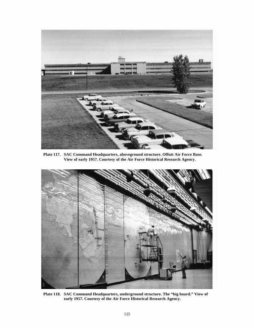
125
Plate 117. SAC Command Headquarters, aboveground structure. Offutt Air Force Base.View of early 1957. Courtesy of the Air Force Historical Research Agency.
Plate 118. SAC Command Headquarters, underground structure. The “big board.” View ofearly 1957. Courtesy of the Air Force Historical Research Agency.
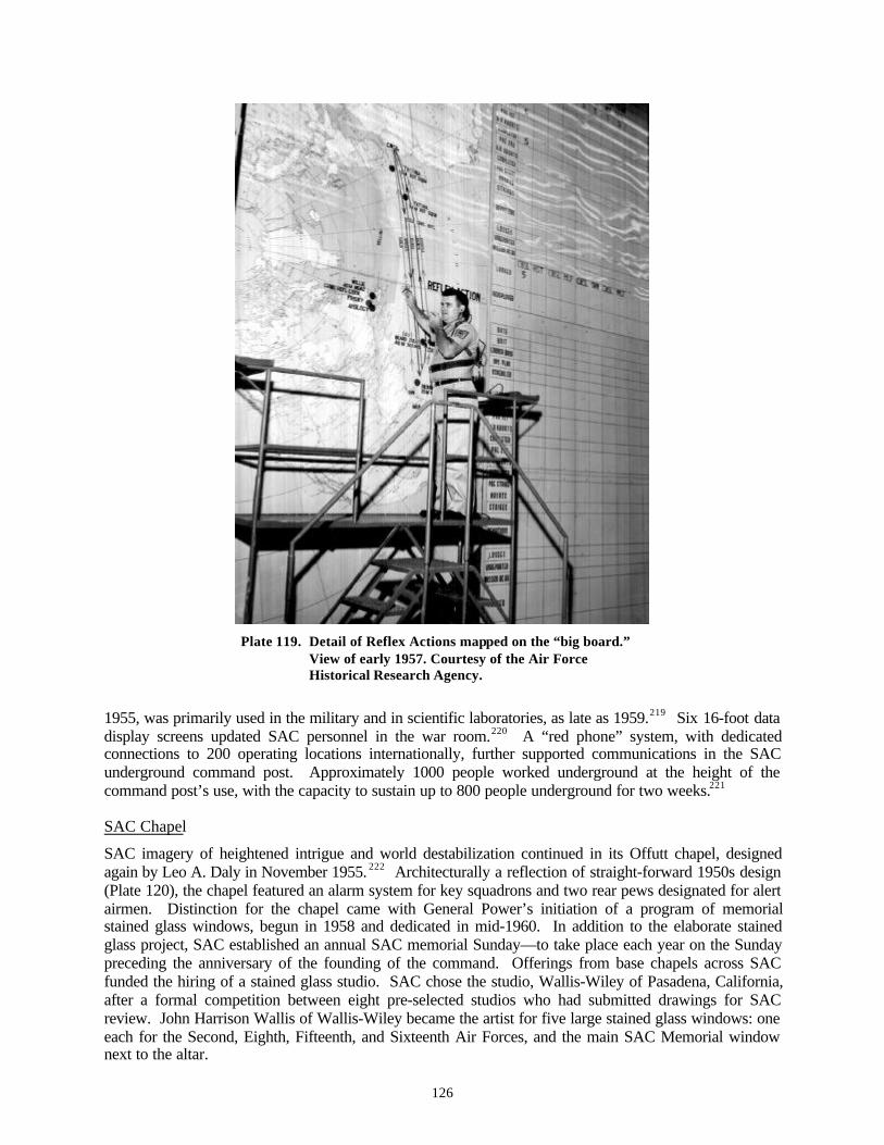
126
Plate 119. Detail of Reflex Actions mapped on the “big board.”View of early 1957. Courtesy of the Air ForceHistorical Research Agency.
1955, was primarily used in the military and in scientific laboratories, as late as 1959.219 Six 16-foot datadisplay screens updated SAC personnel in the war room.220 A “red phone” system, with dedicatedconnections to 200 operating locations internationally, further supported communications in the SACunderground command post. Approximately 1000 people worked underground at the height of thecommand post’s use, with the capacity to sustain up to 800 people underground for two weeks.221
SAC Chapel
SAC imagery of heightened intrigue and world destabilization continued in its Offutt chapel, designedagain by Leo A. Daly in November 1955. 222 Architecturally a reflection of straight-forward 1950s design(Plate 120), the chapel featured an alarm system for key squadrons and two rear pews designated for alertairmen. Distinction for the chapel came with General Power’s initiation of a program of memorialstained glass windows, begun in 1958 and dedicated in mid-1960. In addition to the elaborate stainedglass project, SAC established an annual SAC memorial Sunday—to take place each year on the Sundaypreceding the anniversary of the founding of the command. Offerings from base chapels across SACfunded the hiring of a stained glass studio. SAC chose the studio, Wallis-Wiley of Pasadena, California,after a formal competition between eight pre-selected studios who had submitted drawings for SACreview. John Harrison Wallis of Wallis-Wiley became the artist for five large stained glass windows: oneeach for the Second, Eighth, Fifteenth, and Sixteenth Air Forces, and the main SAC Memorial windownext to the altar.
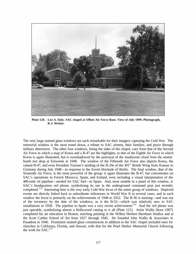
127
Plate 120. Leo A. Daly. SAC chapel at Offutt Air Force Base. View of July 1999. Photograph,K.J. Weitze.
The very large stained glass windows are each remarkable for their imagery capturing the Cold War. Thememorial window is the most toned down, a tribute to SAC airmen, their families, and peace throughmilitary deterrence. The other four windows, lining the sides of the chapel, vary from that of the SecondAir Force in which a map of Korea and a B-47 are the highlights, to that of the Eighth Air Force in whichKorea is again illustrated, but is overshadowed by the portrayal of the mushroom cloud from the atomicbomb test drop at Eniwetok in 1948. The window of the Fifteenth Air Force also depicts Korea, thevalued B-47, and even President Truman’s sending of the B-29s of the 301st Bomb Wing from Kansas toGermany during July 1948—in response to the Soviet blockade of Berlin. The final window, that of theSixteenth Air Force, is the most powerful of the group: it again illustrates the B-47, but concentrates onSAC’s operations in French Morocco, Spain, and Iceland, even including a visual interpretation of the480-mile oil pipeline—needed for SAC fuel—in Spain. And, most notable in a panel of this window, isSAC’s headquarters red phone, symbolizing its use in the underground command post just recentlycompleted.223 Interesting here is the very early Cold War focus of the entire group of windows. Depictedevents are directly linked back to subordinate milestones in World War II in several cases, and in eachwindow the focus is primarily on the achievements of 1948 to 1952. The B-36 is missing—and was outof the inventory by the date of the windows, as is the B-52—which was relatively new to SACinstallations in 1958. The pipeline in Spain was a very recent achievement.224 And the red phone wasjust operable, symbolizing almost a Hollywood casting to it all (Plate 121). Artist Wallis (born 1907)completed his art education in Boston, teaching painting at the Wilbur Herbert Burnham Studios and atthe Scott Carbee School of Art from 1927 through 1945. He founded John Wallis & Associates inPasadena in 1946. Prominent stained glass commissions in addition to the SAC chapel included ones forchurches in California, Florida, and Hawaii, with that for the Pearl Harbor Memorial Church followingthe work for SAC.225

128
Plate 121. Wallis-Wiley Studio. Stained glass window depictingSAC’s Sixteenth Air Force. Red phone, center right.Designed 1958. Courtesy, Nebraska State HistoricalSociety.
Late Cold War SAC Infrastructure
During the terms of Presidents Carter and Reagan, from about 1976 through the end of the Cold War in1991, SAC sponsored a second major phase of new infrastructure. Although construction in support ofthe B-52 bomber mission really required no new major designs for SAC after the late 1950s, thecommand did require new infrastructure for the continuing sophistication in command posts and for theB-1. (During the 1962-1976 period, overall, construction for SAC focused on its missile missions.) Theidea of an established airborne command for SAC, with a parallel airborne post for the President, theSecretary of Defense, and the Joint Chiefs of Staff, dated to 1960, with the initial testing of a Post-AttackCommand and Control System (PACCS) and the National Emergency Airborne Command Post(NEACP). Also known as Looking Glass, PACCS used five KC-135s, configured for airborne commandat Offutt Air Force Base. NEACP, set up at Andrews Air Force Base, is assumed to have also used amodified KC-135. For NEACP, it is assumed that the alert-ready aircraft parked inside the steel-archSAM-CRT hangar built there during 1959-1960—the hangar likely designed by Anton Tedesko to replacethe Kuljian double-cantilever hangar of 1951, and itself essentially a design of 1949-1951. 226 ForPACCS, the backward look for infrastructure was similar. Like the crews of the B-52 bombers andKC-135 tankers on alert at their aprons and moleholes after 1958-1960, the crews of the KC-135smodified for PACCS—known as EC-135s—were trained to achieve airborne status within 15 minutes ofnotice. PACCS was the airborne counterpart to the SAC headquarters below ground command post,mirroring its function directly. The aircraft, however, were part of an existing inventory, and as such didnot require design of new wing hangars. The structures serving as infrastructure for PACCS at Offuttwere standard Luria docks designed in 1958, and part of the escalation in wing hangar construction forSAC to accommodate the deployment of the B-52 and KC-135, generally. They were already in place ina typical pattern for the B-52 / KC-135 by 1959 at Offutt, and, had SAC built a molehole and alert apron
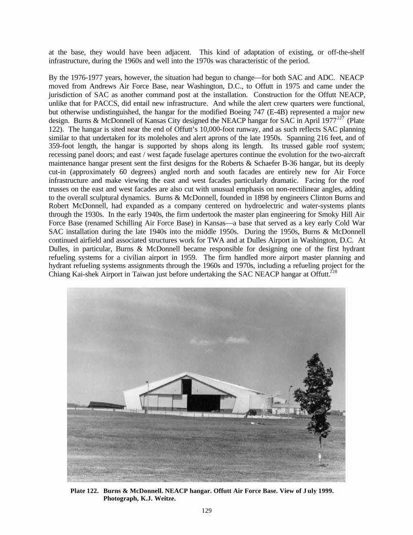
129
at the base, they would have been adjacent. This kind of adaptation of existing, or off-the-shelfinfrastructure, during the 1960s and well into the 1970s was characteristic of the period.
By the 1976-1977 years, however, the situation had begun to change—for both SAC and ADC. NEACPmoved from Andrews Air Force Base, near Washington, D.C., to Offutt in 1975 and came under thejurisdiction of SAC as another command post at the installation. Construction for the Offutt NEACP,unlike that for PACCS, did entail new infrastructure. And while the alert crew quarters were functional,but otherwise undistinguished, the hangar for the modified Boeing 747 (E-4B) represented a major newdesign. Burns & McDonnell of Kansas City designed the NEACP hangar for SAC in April 1977227 (Plate122). The hangar is sited near the end of Offutt’s 10,000-foot runway, and as such reflects SAC planningsimilar to that undertaken for its moleholes and alert aprons of the late 1950s. Spanning 216 feet, and of359-foot length, the hangar is supported by shops along its length. Its trussed gable roof system;recessing panel doors; and east / west façade fuselage apertures continue the evolution for the two-aircraftmaintenance hangar present sent the first designs for the Roberts & Schaefer B-36 hangar, but its deeplycut-in (approximately 60 degrees) angled north and south facades are entirely new for Air Forceinfrastructure and make viewing the east and west facades particularly dramatic. Facing for the rooftrusses on the east and west facades are also cut with unusual emphasis on non-rectilinear angles, addingto the overall sculptural dynamics. Burns & McDonnell, founded in 1898 by engineers Clinton Burns andRobert McDonnell, had expanded as a company centered on hydroelectric and water-systems plantsthrough the 1930s. In the early 1940s, the firm undertook the master plan engineering for Smoky Hill AirForce Base (renamed Schilling Air Force Base) in Kansas—a base that served as a key early Cold WarSAC installation during the late 1940s into the middle 1950s. During the 1950s, Burns & McDonnellcontinued airfield and associated structures work for TWA and at Dulles Airport in Washington, D.C. AtDulles, in particular, Burns & McDonnell became responsible for designing one of the first hydrantrefueling systems for a civilian airport in 1959. The firm handled more airport master planning andhydrant refueling systems assignments through the 1960s and 1970s, including a refueling project for theChiang Kai-shek Airport in Taiwan just before undertaking the SAC NEACP hangar at Offutt.228
Plate 122. Burns & McDonnell. NEACP hangar. Offutt Air Force Base. View of J uly 1999.Photograph, K.J. Weitze.
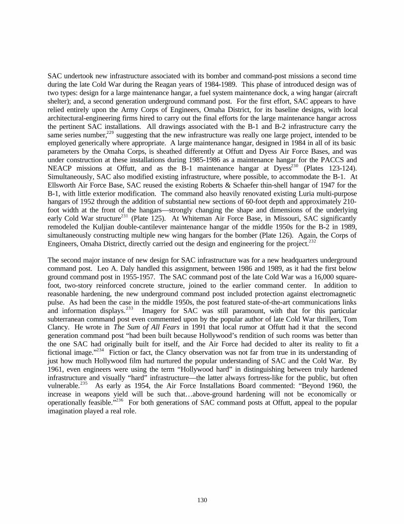
130
SAC undertook new infrastructure associated with its bomber and command-post missions a second timeduring the late Cold War during the Reagan years of 1984-1989. This phase of introduced design was oftwo types: design for a large maintenance hangar, a fuel system maintenance dock, a wing hangar (aircraftshelter); and, a second generation underground command post. For the first effort, SAC appears to haverelied entirely upon the Army Corps of Engineers, Omaha District, for its baseline designs, with localarchitectural-engineering firms hired to carry out the final efforts for the large maintenance hangar acrossthe pertinent SAC installations. All drawings associated with the B-1 and B-2 infrastructure carry thesame series number,229 suggesting that the new infrastructure was really one large project, intended to beemployed generically where appropriate. A large maintenance hangar, designed in 1984 in all of its basicparameters by the Omaha Corps, is sheathed differently at Offutt and Dyess Air Force Bases, and wasunder construction at these installations during 1985-1986 as a maintenance hangar for the PACCS andNEACP missions at Offutt, and as the B-1 maintenance hangar at Dyess230 (Plates 123-124).Simultaneously, SAC also modified existing infrastructure, where possible, to accommodate the B-1. AtEllsworth Air Force Base, SAC reused the existing Roberts & Schaefer thin-shell hangar of 1947 for theB-1, with little exterior modification. The command also heavily renovated existing Luria multi-purposehangars of 1952 through the addition of substantial new sections of 60-foot depth and approximately 210-foot width at the front of the hangars—strongly changing the shape and dimensions of the underlyingearly Cold War structure231 (Plate 125). At Whiteman Air Force Base, in Missouri, SAC significantlyremodeled the Kuljian double-cantilever maintenance hangar of the middle 1950s for the B-2 in 1989,simultaneously constructing multiple new wing hangars for the bomber (Plate 126). Again, the Corps ofEngineers, Omaha District, directly carried out the design and engineering for the project.232
The second major instance of new design for SAC infrastructure was for a new headquarters undergroundcommand post. Leo A. Daly handled this assignment, between 1986 and 1989, as it had the first belowground command post in 1955-1957. The SAC command post of the late Cold War was a 16,000 square-foot, two-story reinforced concrete structure, joined to the earlier command center. In addition toreasonable hardening, the new underground command post included protection against electromagneticpulse. As had been the case in the middle 1950s, the post featured state-of-the-art communications linksand information displays.233 Imagery for SAC was still paramount, with that for this particularsubterranean command post even commented upon by the popular author of late Cold War thrillers, TomClancy. He wrote in The Sum of All Fears in 1991 that local rumor at Offutt had it that the secondgeneration command post “had been built because Hollywood’s rendition of such rooms was better thanthe one SAC had originally built for itself, and the Air Force had decided to alter its reality to fit afictional image.”234 Fiction or fact, the Clancy observation was not far from true in its understanding ofjust how much Hollywood film had nurtured the popular understanding of SAC and the Cold War. By1961, even engineers were using the term “Hollywood hard” in distinguishing between truly hardenedinfrastructure and visually “hard” infrastructure—the latter always fortress-like for the public, but oftenvulnerable.235 As early as 1954, the Air Force Installations Board commented: “Beyond 1960, theincrease in weapons yield will be such that…above-ground hardening will not be economically oroperationally feasible.”236 For both generations of SAC command posts at Offutt, appeal to the popularimagination played a real role.
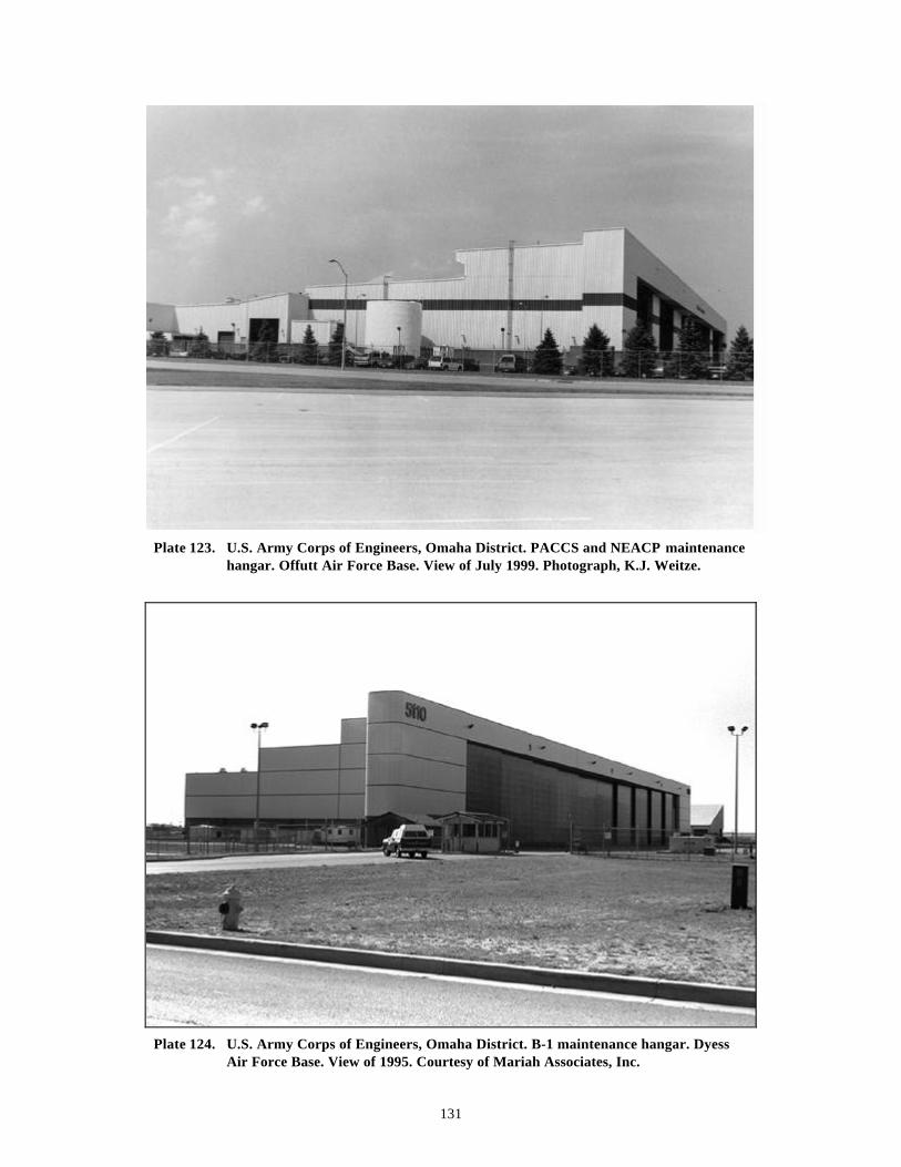
131
Plate 123. U.S. Army Corps of Engineers, Omaha District. PACCS and NEACP maintenancehangar. Offutt Air Force Base. View of July 1999. Photograph, K.J. Weitze.
Plate 124. U.S. Army Corps of Engineers, Omaha District. B-1 maintenance hangar. DyessAir Force Base. View of 1995. Courtesy of Mariah Associates, Inc.
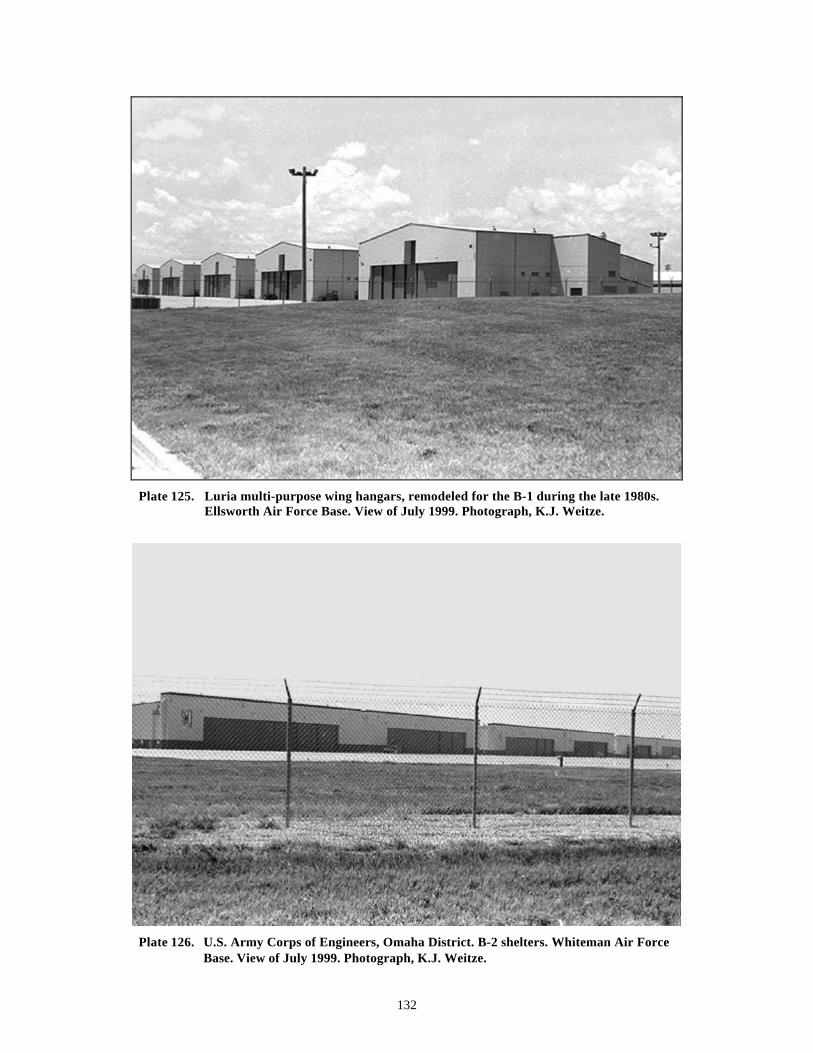
132
Plate 125. Luria multi-purpose wing hangars, remodeled for the B-1 during the late 1980s.Ellsworth Air Force Base. View of July 1999. Photograph, K.J. Weitze.
Plate 126. U.S. Army Corps of Engineers, Omaha District. B-2 shelters. Whiteman Air ForceBase. View of July 1999. Photograph, K.J. Weitze.
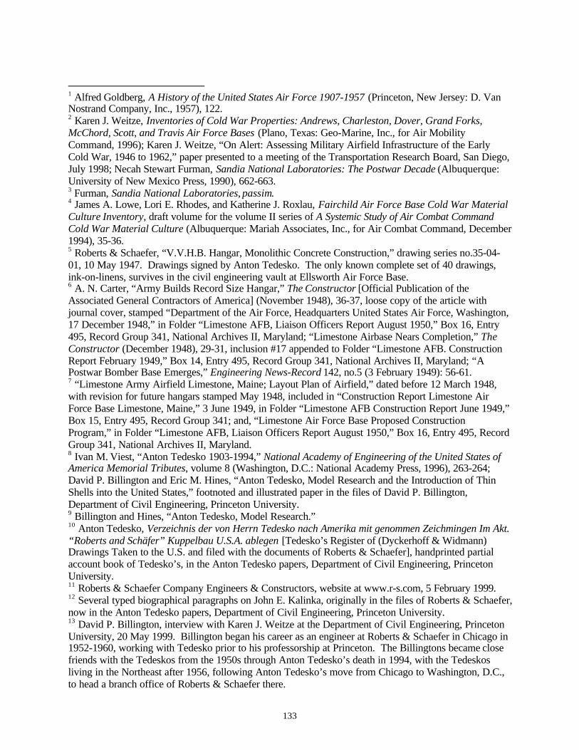
133
1 Alfred Goldberg, A History of the United States Air Force 1907-1957 (Princeton, New Jersey: D. VanNostrand Company, Inc., 1957), 122.2 Karen J. Weitze, Inventories of Cold War Properties: Andrews, Charleston, Dover, Grand Forks,McChord, Scott, and Travis Air Force Bases (Plano, Texas: Geo-Marine, Inc., for Air MobilityCommand, 1996); Karen J. Weitze, “On Alert: Assessing Military Airfield Infrastructure of the EarlyCold War, 1946 to 1962,” paper presented to a meeting of the Transportation Research Board, San Diego,July 1998; Necah Stewart Furman, Sandia National Laboratories: The Postwar Decade (Albuquerque:University of New Mexico Press, 1990), 662-663.3 Furman, Sandia National Laboratories, passim.4 James A. Lowe, Lori E. Rhodes, and Katherine J. Roxlau, Fairchild Air Force Base Cold War MaterialCulture Inventory, draft volume for the volume II series of A Systemic Study of Air Combat CommandCold War Material Culture (Albuquerque: Mariah Associates, Inc., for Air Combat Command, December1994), 35-36.5 Roberts & Schaefer, “V.V.H.B. Hangar, Monolithic Concrete Construction,” drawing series no.35-04-01, 10 May 1947. Drawings signed by Anton Tedesko. The only known complete set of 40 drawings,ink-on-linens, survives in the civil engineering vault at Ellsworth Air Force Base.6 A. N. Carter, “Army Builds Record Size Hangar,” The Constructor [Official Publication of theAssociated General Contractors of America] (November 1948), 36-37, loose copy of the article withjournal cover, stamped “Department of the Air Force, Headquarters United States Air Force, Washington,17 December 1948,” in Folder “Limestone AFB, Liaison Officers Report August 1950,” Box 16, Entry495, Record Group 341, National Archives II, Maryland; “Limestone Airbase Nears Completion,” TheConstructor (December 1948), 29-31, inclusion #17 appended to Folder “Limestone AFB. ConstructionReport February 1949,” Box 14, Entry 495, Record Group 341, National Archives II, Maryland; “APostwar Bomber Base Emerges,” Engineering News-Record 142, no.5 (3 February 1949): 56-61.7 “Limestone Army Airfield Limestone, Maine; Layout Plan of Airfield,” dated before 12 March 1948,with revision for future hangars stamped May 1948, included in “Construction Report Limestone AirForce Base Limestone, Maine,” 3 June 1949, in Folder “Limestone AFB Construction Report June 1949,”Box 15, Entry 495, Record Group 341; and, “Limestone Air Force Base Proposed ConstructionProgram,” in Folder “Limestone AFB, Liaison Officers Report August 1950,” Box 16, Entry 495, RecordGroup 341, National Archives II, Maryland.8 Ivan M. Viest, “Anton Tedesko 1903-1994,” National Academy of Engineering of the United States ofAmerica Memorial Tributes, volume 8 (Washington, D.C.: National Academy Press, 1996), 263-264;David P. Billington and Eric M. Hines, “Anton Tedesko, Model Research and the Introduction of ThinShells into the United States,” footnoted and illustrated paper in the files of David P. Billington,Department of Civil Engineering, Princeton University.9 Billington and Hines, “Anton Tedesko, Model Research.”10 Anton Tedesko, Verzeichnis der von Herrn Tedesko nach Amerika mit genommen Zeichmingen Im Akt.“Roberts and Schäfer” Kuppelbau U.S.A. ablegen [Tedesko’s Register of (Dyckerhoff & Widmann)Drawings Taken to the U.S. and filed with the documents of Roberts & Schaefer], handprinted partialaccount book of Tedesko’s, in the Anton Tedesko papers, Department of Civil Engineering, PrincetonUniversity.11 Roberts & Schaefer Company Engineers & Constructors, website at www.r-s.com, 5 February 1999.12 Several typed biographical paragraphs on John E. Kalinka, originally in the files of Roberts & Schaefer,now in the Anton Tedesko papers, Department of Civil Engineering, Princeton University.13 David P. Billington, interview with Karen J. Weitze at the Department of Civil Engineering, PrincetonUniversity, 20 May 1999. Billington began his career as an engineer at Roberts & Schaefer in Chicago in1952-1960, working with Tedesko prior to his professorship at Princeton. The Billingtons became closefriends with the Tedeskos from the 1950s through Anton Tedesko’s death in 1994, with the Tedeskosliving in the Northeast after 1956, following Anton Tedesko’s move from Chicago to Washington, D.C.,to head a branch office of Roberts & Schaefer there.

134
14 “Publications on Shell Structures in the English Language,” a comprehensive typed list of articlesappearing in British, American, and Canadian engineering, concrete industry, and architectural journalsfrom 1929 through August 1944, 5pp. In the Anton Tedesko papers, Department of Civil Engineering,Princeton University.15 Billington and Hines, “Anton Tedesko, Model Research” and “Publications on Shell Structures in theEnglish Language.”16 Carl W. Condit, American Building Art The Twentieth Century (New York: Oxford University Press,1961), 179-182.17 “ZD Buildings Constructed in North America, Roberts & Schaefer Company, Engineers, Chicago,Illinois,” a comprehensive typed list of 45 structures, 1934-1944, 5pp. In the Anton Tedesko papers,Department of Civil Engineering, Princeton University; Billington and Hines, “Anton Tedesko, ModelResearch” and “Publications on Shell Structures in the English Language.”18 Franz Dischinger, Dyckerhoff & Widmann A.G., Eisenbetonschalendächer Zeiss-Dywidag zurUeberdackung weitgespannter Räume (Liege, Belgium: Editions “La Technique des Travaux”, 1930),with prefatory comments in French. In the Anton Tedesko papers, Department of Civil Engineering,Princeton University.19 Anton Tedesko, Verzeichnis der von Herrn Tedesko nach Amerika; Billington and Hines, “AntonTedesko, Model Research.”20 Ulrich Finsterwalder, Dyckerhoff & Widmann, to Anton Tedesko, Roberts & Schaefer,“Flugzeugschuppen Portland Oregon,” business correspondence, 15 November 1932; Finsterwalder toTedesko, “Flugzeughallen Navy Base—San Diego, California,” business correspondence, 7 July 1939. Inthe Anton Tedesko papers, Department of Civil Engineering, Princeton University.21 “Personal Histories of Principals and Staff Associates,” two-page typescript in the Anton Tedeskopapers, Department of Civil Engineering, Princeton University; Viest, “Anton Tedesko,” MemorialTributes, 265.22 John E. Kalinka, “Monolithic Concrete Construction for Hangars,” The Military Engineer, 32, no.181(January-February 1940): 54; David P. Billington, “Anton Tedesko: Thin Shells and Esthetics,” paperpresented at the American Society of Civil Engineers annual conference, New York, May 1981;subsequently published in the Journal of the Structural Division, Proceedings of the American Society ofCivil Engineers, 108, no.ST11 (November 1982): 2539-2554.23 “Report by Project Officer on War Department Mission to European Underground Factories,” 5 March1948, in Folder “Underground Sites: Report of Mr. Nottingham on Mission to Germany,” Box 33, Entry464, Record Group 341, National Archives II, Maryland.24 Franz Dischinger and Ulrich Finsterwalder, Neuere Entwicklungsformen der Schalen-Bauweise: SystemZeiss-Dywidag (Berlin: Verlag Ernst & Sohn, 1932). In the Anton Tedesko papers, Department of CivilEngineering, Princeton University.25 “ZD Buildings Constructed in North America;” “Partial Listing of Projects Completed Since 1940,”typed list of projects, 1940-ca.1953, with costs, in the Anton Tedesko papers, Department of CivilEngineering, Princeton University; Billington, “Anton Tedesko: Thin Shells and Esthetics;” Arthur J.Boase, “Concrete Building Design Trend Shaped by Clear Space Needs,” Engineering News-Record 135,no.16 (18 October 1945): 136-140.26 “Airfield and Hangar Structures by Roberts and Schaefer Company,” black ring binder of large-formatphotographs, articles, and job lists, ca.1956, in the Anton Tedesko papers, Department of CivilEngineering, Princeton University.27 Roberts and Schaefer Co. Engineers, Z-D System of Reinforced Concrete Construction Thin ShellRoofs, brochure (Chicago: Roberts & Schaefer, July 1946), in the Anton Tedesko papers, Department ofCivil Engineering, Princeton University.28 Anton Tedesko, “Low-Cost Repairs Restore Concrete to Design Strength,” Civil Engineering 17, no.1(January 1947): 9-12.29 “Hangars by Roberts and Schaefer Co. Chicago New York,” two presentation binders of 8x10-inchphotographs, ca.1956, in the Anton Tedesko papers, Department of Civil Engineering, PrincetonUniversity.

135
30 Anton Tedesko, “Wide-Span Hangars for the U.S.Navy,” Civil Engineering 11, no.12 (December1941): 697-700; Robert Zaborowski and Otto Gruenwald, “Monolithic Concrete Seaplane Hangars,” CivilEngineering 14, no.8 (August 1944): 355-358; “ZD Buildings Constructed in North America;” Condit,American Building, 181.31 “Key Personnel” rosters, with brief biographies, in the Anton Tedesko papers, Department of CivilEngineering, Princeton University.32 Department of the Army, Staff Message Center, Incoming Classified Message, 18 February 1948, inFolder “Underground Sites: Reports by German Scientists,” Box 36, Entry 464, Record Group 341,National Archives II.33 Billington, “Anton Tedesko: Thin Shells and Esthetics.”34 Anton Tedesko, “Construction plant for shell structures should be carefully coordinated,” CivilEngineering 23, no.2 (February 1953): 48.35 Louis W. Prentiss, “Thin Concrete Arch Roof Provides 340-Ft. Clear Span for Bomber Hangar,” CivilEngineering 19, no.2 (February 1949): 34-38; “A Postwar Bomber Base Emerges,” Engineering News-Record.36 John E. Allen, “Construction of Long-Span Concrete Arch Hangar at Limestone Air Force Base,”Journal of the American Concrete Institute , February 1950, 405-414; Anton Tedesko, discussion of theAllen paper, Ibid, 416-418; William M. Blair, “B-29 Base Pushes Conversion to B-36,” New York Times,5 June 1949. Robert Zaborowski, “Hangars Are What You Make Them,” Airports and Air Carriers,February 1949, two-page reprint in the Anton Tedesko papers, Department of Civil Engineering,Princeton University.37 Charles S. Whitney, “Cost of Long-Span Concrete Shell Roofs,” Journal of the American ConcreteInstitute , 21, no.10 (June 1950): 765-776; Charles S. Whitney, “Shell design adaptable to many uses,”Civil Engineering 23, no.2 (February 1953): 37-39.38 Otto Gruenwald, Eric C. Molke, and Robert Zaborowski, “Discussion of a paper by Charles S.Whitney: ‘Cost of Long-Span Concrete Shell Roofs,’” Journal of the American Concrete Institute, 21,no.10 (June 1950): 776-1 – 776-8.39 Thomas C. Kavanagh, “Othmar Hermann Ammann,” National Academy of Engineering of the UnitedStates of America Memorial Tributes, volume 1 (Washington, D.C.: National Academy of Engineering,1979), 7-9.40 “Partial Listing of Projects Completed since 1940;” Robert Zaborowski, “Thin-shell-arch hockeystadium for Quebec built in 10 months,” Civil Engineering 21, no.10 (October 1951): 36-40; AntonTedesko, “Thin-shell arch selected for Denver Coliseum,” Civil Engineering 24, no.7 (July 1954): 46-50;Boyd G. Anderson, “Cylindrical roof for circular coliseum,” Engineering News-Record 145, no.18 (2November 1950): 30-33..41 “Hangars by Roberts and Schaefer Co. Chicago New York,” two presentation binders.42 AW 39-01-66, “Hangar, Maintenance Organizational Pull Thru Type,” 20 July 1956; AW 39-01-67,“Hangar, Maintenance Organizational Pull-Thru Type,” 7 March 1958, 105mm microfiche copies ofdrawings held at the U.S. Army Corps of Engineers History Office, Humphreys Engineering Center, FortBelvoir, Virginia.43 “Thin-Shell Roof Will Be Prestressed,” Engineering News-Record 157, no.22 (31 May 1956): 28;“Undulated Thin-Shell Hangar Roof Spans Big Bays,” Engineering News-Record 158, no.10 (7 March1957): 44-47.44 Billington, “Anton Tedesko: Thin Shells and Esthetics,” 2547-2548.45 Viest, “Anton Tedesko,” Memorial Tributes, 265; Billington, interview with Weitze, 20 May 1999.46“Limestone Army Airfield Limestone, Maine; Layout Plan of Airfield,” May 1948; “Limestone AirForce Base Proposed Construction Program,” August 1950.47 Karen J. Weitze and Joe E. Freeman, Historic American Engineering Record, Dugway ProvingGround, German Village Complex, HAER No. UT-35 (Plano, Texas: Geo-Marine, Inc., for the U.S. ArmyCorps of Engineers, Fort Worth District, 1996).48 Condit, American Building, 49; “Bausystem für Flugzeughangars,” Vertiefungsarbeit Mobile Gebäude,www.architektur.uni-stuttgart.de, 26 March 1999.
136
49 Headquarters, USAF, History of the Assistant Chief of Staff, Installations 1 January 1954 to 30 June1954, Directorate of Construction, Engineering Division, unpaginated. The Air Force, or AAF before it,numbered Wachsmann’s contract and/or drawings AF33(600)-22947.50 Paul Weidlinger, “Architecture and Reinforced Concrete,” Pencil Points (August 1943): 58-66.51 “Applied Science,” “Airport Facilities,” and “Blast-Resistant Structures,” www.wai.com, 23 June 1999.52 Arsham Amirikian, “Navy Builds 300-Ft. Welded Arch Hangar,” Engineering News-Record 144, no.4(26 January 1950): 34-35.53 “Hangars by Roberts and Schaefer Co. Chicago New York,” two presentation binders; “World’sLargest Steel Arched Hangars,” Architectural Record, April 1950: 161-164; “Long Steel Arch HangarsErected Fast,” Engineering News-Record 144, no.21 (25 May 1950): 40-42; “Huge Steel-Arch Hangars,”Civil Engineering 21, no.4 (April 1951): 11; “Design Concepts Change at New York InternationalAirport,” Civil Engineering 25, no.11 (November 1955): 58-61; “Hangar Design Races To Keep Up Withthe Planes,” Engineering News-Record 156, no.9 (1 March 1956): 42-44.54 Headquarters, USAF, History of the Directorate of Installations 1 January 1953 – 30 June 1953,Architectural and Engineering Division section, unpaginated.55 Ibid.56 Mills & Petticord, drawings no.39-01-27, 39-01-28, 39-01-34, 39-01-35, and 39-01-36, three sizes ofSAC bomber maintenance hangar: basic (one B-36 or six fighter aircraft); medium bomber; heavybomber, with expanded hangar designs for the medium and heavy bomber structures, January-February1951; and, drawings no.39-01-43, 39-01-44, 39-01-45, 39-01-46, and 39-01-47, three sizes of SACbomber maintenance hangar as for the original series, August 1951: both series as card file references todrawings no longer extant, History Office, U.S. Army Corps of Engineers, Humphreys EngineeringCenter, Fort Belvoir, Virginia.57 Condit, American Building, 49.58 Mills & Petticord, “Hangar Maintenance Expansible Double-Cantilever,” drawing no.39-01-4, showingthe basic hangar with two expansions, 24 August 1951, single surviving drawing from the Mills &Petticord designs for the SAC maintenance hangar, 105mm microfiche copy, History Office, U.S. ArmyCorps of Engineers, Humphreys Engineering Center, Fort Belvoir, Virginia.59 Mills & Petticord, drawing no.39-01-34, February 1951, card file references to a set of drawings nolonger extant, History Office, U.S. Army Corps of Engineers, Humphreys Engineering Center, FortBelvoir, Virginia; Pacific Iron and Steel Company, Los Angeles, “Hangar: Architectural Elevations;Architectural First Floor Slab; Structural Foundation Plan,” drawing no.39-01-01, 25 April 1951, civilengineering vault, Kirtland Air Force Base. SAC built two additional Kuljian medium bomber,expansible, double cantilever hangars (Building 1000 and 1002) at Kirtland bracketing the Mills &Petticord hangar (Building 1001) during 1952-1955.60 Air Force Installations Representative, North Atlantic Division, “French Morocco AFIRO InspectionVisit,” November 1951, 4, 8, 57, and map: in Folder “French Morocco AFIRO Inspection Visit,” Box 4,Entry 495, Record Group 341, National Archives II, Maryland.61 Arthur Kuljian, interview with Karen J. Weitze, at Kuljian Corporation, Philadelphia, 31 March and 21May 1999.62 “Standardized hangars cantilever 104 ft,” Engineering News-Record 149, no.5 (31 July 1952): 42-43.63 Ibid ; “Drawings Project Schedule” volume, Kuljian Corporation Office, Philadelphia; hand-annotatedand dated card index of drawings and 105mm microfiche drawings copies for the Kuljian SAC hangar,History Office, U.S. Army Corps of Engineers, Humphreys Engineering Center, Fort Belvoir, Virginia:completed drawings series dated 10 December 1951, drawings no.39-01-43, 39-01-44, 39-01-45, 39-01-46, and 39-01-47.64 Hand-annotated card index, Kuljian SAC hangar.65 Kuljian, interview with Weitze, 31 March and 21 May 1999; “Technical Aid for Foreign PowerProject,” reprint from Power Engineering, June 1951, offprint provided by Kuljian Corporation; TheKuljian Corporation, Kuljian World Wide Services, brochure, undated, provided by Kuljian Corporation;“Kuljian Airport Planning, Design and Engineering,” spiral-bound binder of engineering offprints andcompany brochures compiled by Arthur Kuljian for Karen Weitze, March 1999.
137
66 Eugene J. Peltier, “Arsham Amirikian,” National Academy of Engineering of the United States ofAmerica Memorial Tributes, volume 5 (Washington, D.C.: National Academy Press, 1992), 15-17.Amirikian published frequently in the Journal of the American Concrete Institute, Civil Engineering, andEngineering News-Record, especially with regards to early concerns and ideas for designing to protectagainst nuclear blast effects. The connection between Amirikian and Tedesko is reinforced by theRoberts & Schaefer steel prototype dirigible hangar of 1942. A photograph of the hangar exists in theCivil Engineering Archives, Princeton University. See also: “Blimp Hangars Set New Timber ArchRecord,” Engineering News-Record 129, no.17 (22 October 1942): 110-111, and “Blimp Hangars Builtby Contrasting Methods,” Engineering News-Record 129, no.25 (17 December 1942): 65-70.67 “Kuljian Airport Planning, Design and Engineering;” also, as estimated from building footprints on thecomprehensive master plans for the USAF, Directorate of Installations, 1 October 1957.68 Edwin M. Eads, “Double-cantilever hangar encloses 3 ½ acres,” Civil Engineering 26, no.5 (May1956): 61-63; “Standardized hangars cantilever 104 ft,” Engineering News-Record 149, no.5 (31 July1952): 42-43.69 These eight bases are now all closed military facilities, with the exception of Biggs which is now a partof Fort Bliss under the jurisdiction of the U.S. Army.70 Ibid , 63.71 “New Type Hangars Go Up Around the World,” Engineering News-Record 154, no.19 (12 May 1955):34-38.72 Headquarters, USAF, History of the Directorate of Installations 1 July 1953 – 31 December 1953,Architectural and Engineering Division, 4.73 Kuljian Corporation, “Double Cantilever Maintenance Hangars, Corps of Engineers,” numbered job listby Air Force installation and provided engineering service, Kuljian Corporation Offices, Philadelphia,undated.74 93rd Bombardment Wing, Fifteenth Air Force, Strategic Air Command, History of 93rd BombardmentWing, Medium, Castle Air Force Base, September 1953, 56.75 Hand-annotated card index, Mills & Petticord SAC hangar, 24 August 1951 version.76 Headquarters, USAF, History of the Assistant Chief of Staff, Installations, 1 January 1955 to 30 June1955, “Directorate of Construction” section: 28.77 M.S. Agbabian, chairman, updating committee, Design of Structures to Resist Nuclear WeaponsEffects, Manual of Engineering Practice No.42, Committee on Dynamic Effects of the Structural Divisionof the American Society of Civil Engineers (New York: American Society of Civil Engineers, revisededition 1985), 180-181. First published in 1961, with initial preparation efforts beginning in 1958.78 Arsham Amirikian, “Can We Design for Atomic Blasts?” Civil Engineering 20, no.11 (November1950): 27-28; Arsham Amirikian, “How to design for H-blast fringe areas,” Engineering News-Record152, no.15 (15 April 1954): 21-22; and, L.L. Wise, “Atomic Test Shows How Buildings Stand Up,”Engineering News-Record 154, no.19 (12 May 1955): 21-22.79 “FCDA offers minimum design standards for atomic age industrial buildings,” Engineering News-Record 153, no.1 (1 July 1954): 26.80 Weitze, Inventories of Cold War Properties.81 History of the Assistant Chief of Staff, Installations 1 January 1954 to 30 June 1954, EngineeringDivision, Directorate of Construction section, unpaginated.82 Headquarters, USAF, History of the Assistant Chief of Staff, Installations 1 July 1955 to 31 December1955, volume 6, 74.83 Headquarters, USAF, History of the Assistant Chief of Staff, Installations, 1 January 1957 to 30 June1957, volume 8, 33.84 Ibid , 61; Headquarters, USAF, History Directorate of Installations 1 January 1958 – 30 June 1958,volume 8, 72; Headquarters, USAF, History Directorate of Installations 1 July 1958 to 31 December1958, volume 7, 70; Headquarters, USAF, History of the Directorate of Civil Engineering 1 January 1959to 30 June 1959, volume 9, 41.85 “Steel Trussed Arches Span 360 Ft in Hangar,” Engineering News-Record 157, no.6 (9 August 1956):36-38.

138
86 “Record three-hinged arch spans 278 ft,” Engineering News-Record 152, no.14 (8 April 1954): 33.87 “Four acres of roof—but only two columns inside,” Engineering News-Record 151, no.12 (17September 1953): 45.88 Waldo G. Bowman, “Big Hangars and Prestressed Taxiway,” Engineering News-Record 155, no.17 (27October 1955): 34-38.89 “Hangar Design Races to Keep Up,” 1 March 1956; Charles J. Projop, “Pan American Airwayshangar,” Civil Engineering 27, no.10 (October 1957): 60-63; “Cables Support 130-Ft Hangar Roof,”Engineering News-Record 157, no.26 (27 December 1956): 39-40; “Cables support cantilevered hangarroof,” Civil Engineering 26, no.12 (December 1956): 44-47; E.P. Littlejohn, “Trans World AirlinesHangar,” Civil Engineering 27, no.10 (October 1957): 64-65.90 “Largest Cantilevers to Support Roof Hangar,” Engineering News-Record 158, no.8 (21 February1957): 46; “Longest Cantilever Girders Now Erected,” Engineering News-Record 160, no.5 (30 January1958): 25; A.A. Braccia, “Big Jets Sheltered Under Long Cantilever,” Engineering News-Record 162,no.16 (23 April 1959): 38-40; “Newark Airport’s Next Hangar…Will Have 140 Ft Cantilevered Trusses,”Engineering News-Record 158, no.13 (28 March 1957): 26.91 “Steel Trusses Cantilever 150 Ft…Over Hangar for Biggest Planes,” Engineering News-Record 161,no.6 (7 August 1958): 53; “Hangar to Get Hung Steel Roof,” Engineering News-Record 160, no.21 (22May 1958): 26; “Tomorrow’s Jet Age is Here Now,” Engineering News-Record 162, no.23 (11 June1959): 34-36: “Hangar’s Trusses Cantilever 177 Feet,” Engineering News-Record 162, no.24 (18 June1959): 47.92 Royal C. Flanders, “Cantilever Hangar Design,” The Military Engineer 51, no.342 (July-August 1959):284-286; Willgoos, Strobel, Panero and Knoerle, “Aircraft Maintenance Facilities. NAS HangarBldg.,”drawing series no.39-01-40, 3 November 1959, 105mm microfiche copy, History Office, U.S.Army Corps of Engineers, Humphreys Engineering Center, Fort Belvoir, Virginia.93 Walter G. Hiner, “Combat Airplane Hangars,” The Military Engineer 37, no.235 (May 1945): 188.94 “Portable ‘Nose-In’ Hangar of Steel and Canvas,” Engineering News-Record 134, no.12 (22 March1945): 106-108.95 USAF, Directorate of Installations, Master Plans, October 1957.96 Hiner, “Combat Airplane Hangars,” 186-188.97 Photograph of B-50 in repair at Biggs Air Force Base, 14 September 1951, and, photograph of B-36 inrepair at Ellsworth Air Force Base, undated: in Strategic Air Command, Eighth Air Force History 1January – 30 June 1953; photographs of B-36s and engine repair docks, Carswell Air Force Base(undated) and Walker Air Force Base (28 August 1952): in Strategic Air Command, Eighth Air ForceHistory 1 July – 31 December 1952.98 “Nose Dock for B-29 & B-50,” drawing series no.39-05-04, 10 March 1952, annotated card index forsuperceded definitive drawings, History Office, U.S. Army Corps of Engineers, Humphreys EngineeringCenter, Fort Belvoir, Virginia.99 “Final Report on Test of Airplane Maintenance Shelter (Bushman-Moore Co.),” 21 December 1942, inFolder “3-42-78,” Box 195, Entry 191, Record Group 341; “Final Report on Test of Shelter,Maintenance, for B-29 Airplane,” in Folder “(M-4) 484,” Box 256, Entry 191, Record Group 341; and ,“Final Report on Comparative Test (Climatic Hangar Cold) of Docks, Maintenance, Types I and II,” inFolder “3-47-91,” Box 342, Entry 191, Record Group 341. All at the National Archives II, Maryland.100 “Hangar—Nose—M.B.” (January and August 1951 versions) and “Hangar—Nose, HB” (February1951), drawings no. 39-05-01 and 39-01-42; and, 39-05-02, annotated index cards for supercededdefinitive drawings, History Office, U.S. Army Corps of Engineers, Humphreys Engineering Center, FortBelvoir, Virginia.101 Mills & Petticord, “Hangar—Nose—M.B., Plans, Elevations & Section,” drawing series no.39-01-42,105mm microfiche copy, History Office, U.S. Army Corps of Engineers, Humphreys Engineering Center,Fort Belvoir, Virginia.102 Luria Engineering Corporation, with Peter A. Strobel, consulting engineer, New York, “Department ofthe Air Force, B-36 Maintenance Dock, contract no. AF 33(038)–18824; Foundation, Floor Plan & Notes;Plans, Elevations, Sections; Torus Closure Tube; and Jet Service Platform,” 23 April 1951.

139
103 SSgt William E. Stevens and AIC Paul G. Tyson, The Loring Episode (Loring Air Force Base: 42nd
Bombardment Wing History Office, 9 April 1980), 27; Karen Lewis, R. Blake Roxlau, and Katherine J.Roxlau, A Baseline Inventory of Cold War Material Culture at Ellsworth Air Force Base, volume II-7 ofA Systemic Study of Air Combat Command Cold War Material Culture (Albuquerque: Mariah Associates,Inc., for Air Combat Command, August 1997); “Foundation for Maintenance Docks: Site Plan & Index,and, Layout & Grading Plan, Rapid City [Ellsworth] Air Force Base,” 20 June 1951.104 Strategic Air Command, “Explosion Proof Telephones for Luria Docks,” 29 September 1952. Held inthe civil engineering vault, Ellsworth Air Force Base.105 Mapping of the B-36 wing hangar suggests that SAC intended the structure to be erected in groups ofeight, in one of two distinctive configurations at a flightline apron, at each of the cold weather basesassociated with an alert Q Area. Ellsworth and Loring did in fact have eight of these hangars; Fairchild,six; and Westover, six or nine.106 History of the Directorate of Installations 1 January 1953—30 June 1953, “Architectural andEngineering Division.”107 The Luria-Strobel B-36 wing hangars have a distinctive footprint and appear on the 1957 installationmaster plans for the Air Force. The Mariah 1995-1997 ACC reports verify through file notes, maps, andphotographs the presence of these docks at Ellsworth, Fairchild, and Loring Air Force Bases.108 384th Air Refueling Wing, History Office, McConnell AFB A Historical Perspective (Wichita:McConnell AFB, 1986), aerial photograph of 1952.109 Headquarters, Strategic Air Command, The SAC Bombardment Training Program 1946-1959,Historical Study No.80, 8-11.110 Comprehensive master plans for the USAF, Directorate of Installations, 1 October 1957.111 James A. Lowe, John A. Evaskovich, and Katherine J. Roxlau, A Baseline Inventory of Cold WarMaterial Culture at Seymour Johnson Air Force Base, volume II-26 of A Systemic Study of Air CombatCommand Cold War Material Culture (Albuquerque: Mariah Associates, Inc., for Air Combat Command,July 1997). A B-47 wing hangar is clearly visible in an aerial photograph of Seymour-Johnson, 29October 1965. This structure, Building No. 4828, is photographed only from the front in the Mariahinventory, and as such does not offer the reader a clear view of the sharply angled facade (although theswept back facade is apparent). Sequential aerial photographs exist in the Mariah project files.112 Luria Engineering Corporation, “Hangar, Wing, Multi-Purpose,” drawing series no.39-01-54, 15October 1952, 105mm microfiche copy, History Office, U.S. Army Corps of Engineers, HumphreysEngineering Center, Fort Belvoir, Virginia.113 Luria Engineering Corporation, “Wing Hangar for Medium & Heavy Aircraft,” drawing series no.39-01-50, 15 August 1951, 105mm microfiche copy; and, entry, 7 August 1951, annotated card index,History Office, U.S. Army Corps of Engineers, Humphreys Engineering Center, Fort Belvoir, Virginia.114 Luria Engineering Corporation, “Hangar, Wing, Multi-Purpose,” drawing series evolved from no.39-01-50, including at least no.39-01-53 (November 1952) and no.39-01-54 (October 1952). Each numberedset of drawings included 27 sheets. That of no.39-01-53 is verified as-built at Ellsworth and Whiteman,and may be the standardized “version” of the Luria 1951-1952 design effort selected for buildout.115 History of the Directorate of Installations 1 January 1953 – 30 June 1953.116 Andrus Martin Associates, “Multipurpose Wing Hangar (Warm Climate),” drawing series no.39-05-08, 5 August 1953, annotated card index, History Office, U.S. Army Corps of Engineers, HumphreysEngineering Center, Fort Belvoir, Virginia.117 “Revisions. Strobel and Salzman. Hangar, Wing, Multi-Purpose. Foundation Details and Schedule 30psf,” drawing series no.39-01-53, 28 January 1953. Held in the civil engineering vault, Whiteman AirForce Base.118 “Revisions. Kuljian Corporation. Hangar, Wing, Multi-Purpose,” drawing series no.39-01-53, beforeMarch 1956. Held in the civil engineering vault, Whiteman Air Force Base.119 The figure of 130 is approximate, and is calculated from footprints on the 1957 installation masterplans across the Air Force.120 Leo A. Daly Company, “Modification of Wing Hangars: Elevations, and, Cross Sections and Details,”drawing series no.39-05-03, 22 August 1955.

140
121 42nd Bombardment Wing, Strategic Air Command, 42nd Bombardment Wing, Heavy 1-31 July 1957, 8.122 Stevens and Tyson, The Loring Episode, 87.123 Luria Engineering Company, “AMC Standard Aircraft Weather Shelter, Contract No. AF 33 (602) –7888,” drawing no. E-AF 2200-FI, 26 July 1956.124 Reynolds-Smith-Hills, “USAF Dock, Maintenance, Large Aircraft,” drawing series no.39-05-10, 18January 1957; and, “Dock, Maintenance, Medium Aircraft,” drawing series no.39-05-09, annotated cardindex, History Office, U.S. Army Corps of Engineers, Humphreys Engineering Center, Fort Belvoir,Virginia.125 The figure of 80 is approximate, and is calculated from footprints on the 1957 installation master plansacross the Air Force.126 Headquarters, USAF, History of the Assistant Chief of Staff, Installations, 1 January 1957 to 30 June1957, 33.127 Luria Engineering Company, “Aircraft Servicing Dock, Contract No. AF33 (600)-36934, December1957 – May 1958.128 Headquarters, USAF. Air Force, History Directorate of Civil Engineering 1 July 1959 – 31 December1959, 45.129 Headquarters, USAF, History of the Directorate of Civil Engineering 1 July 1960 to 31 December1960, 24, 51-52.130 Headquarters, USAF: History of the Directorate of Civil Engineering 1 January 1961 to 30 June 1961,41; History of the Directorate of Civil Engineering 1 July 1961 to 31 December 1961, 10-11; History ofthe Directorate of Civil Engineering 1 January 1962 – 30 June 1962, 20; History of the Directorate ofCivil Engineering 1 July 1962 – 31 December 1962, 6-7.131 Karen J. Weitze, Guided Missiles at Holloman Air Force Base: Test Programs of the United States AirForce in Southern New Mexico, 1947-1970, Holloman Air Force Base Cultural Resources PublicationNo.5. (El Paso: Geo-Marine, Inc., for Air Combat Command, November 1997), 177; Headquarters, U.S.Air Force, “Plans Division,” History of the Directorate of Installations 1 January 1952 – 30 June 1952,11.132 “Experimental Barracks at Camp Grant,” Engineering News-Record 126, no.21 (22 May 1941): 50-52.133 Lori E. Rhodes, Patience Elizabeth Patterson, and Katherine J. Roxlau, A Baseline Inventory of ColdWar Material Culture at Offutt Air Force Base, volume II-23 of A Systemic Study of Air CombatCommand Cold War Material Culture (Albuquerque: Mariah Associates, Inc., for Air Combat Command,October 1997), 23, 48.134 Lewis, Roxlau, and Roxlau, A Baseline Inventory at Ellsworth Air Force Base; James A. Lowe, DavidP. Stanley, and Katherine J. Roxlau, A Baseline Inventory of Cold War Material Culture at Loring AirForce Base, volume II-16 of A Systemic Study of Air Combat Command Cold War Material Culture(Albuquerque: Mariah Associates, Inc., for Air Combat Command, August 1997); Ellsworth and Loringinstallation plans from the 1957 Air Force-wide master plan set.135 “Two Bases for the Biggest Strategic Bombers,” Engineering News-Record 158, no.9 (28 February1957): 40-44. The footprint for the SAC steel dormitory is quite distinctive when accurately mapped: atPease Air Force Base, the footprints are unmistakable on the 1957 installation master plan.136 Detroit Steel Products Company, “Fenestra Metal Building Panels,” The Military Engineer 44, no.299(May-June 1952): 6.137 Detroit Steel Products Company, “Fenestra Metal Building Panels,” The Military Engineer 44, no.300(July-August 1952): 33.138 Ibid.139 The key drawing sets are Headquarters Strategic Air Command, Air Installation Division, “AirmenBarracks,” series numbered SAC-HQ B-406. The larger dormitory set has 28 drawings; the smaller, 27.Baseline date for the series is interpreted as 1951. No original drawings remain at Offutt, but those atEllsworth are dated 1 August 1952.140 “Portable Schoolroom Follows Population,” Engineering News-Record 154, no.24 (16 June 1955): 63.141 These locations are derived from an analysis of the 1957 master plan for installations across the AirForce.
141
142 Headquarters, USAF, History of the Assistant Chief of Staff, Installations, 1 July 1954 to 31 December1954, “Directorate of Construction” section: 19; and, Headquarters, USAF, History of the Assistant Chiefof Staff, Installations, 1 January 1955 to 30 June 1955, “Directorate of Construction” section: 25.143 Headquarters, USAF, History of the Assistant Chief of Staff, Installations, 1 July 1956 to 31 December1956, 62.144 Lenore Fine and Jesse A. Remington, The Corps of Engineers: Construction in the United States,volume in United States Army in World War II: The Technical Series (Washington, D.C.: Office of theChief of Military History, United States Army), 441-443.145 Ibid , 611-612, 614-615.146 Ibid , 616-639; Gayle McFadden and Reuben M. Haines, “Design of Airfield Pavements Developed byU.S. Engineer Department,” Civil Engineering 15, no.3 (March 1945): 135-138.147 Fine and Remington, The Corps of Engineers, 640, 644-648.148 Major General J.B. Newman and Lieutenant Colonal H.E. Brown, “Modern military aircraft changeairfield design concepts,” Civil Engineering 21, no.4 (April 1951): 34-38.149 Goldberg, History of the United States Air Force, 195.150 “Tailoring airfields for modern planes,” Engineering News-Record 146, no.20 (17 May 1951): 43.151 Lee B. Washbourne, “Effect of Jet Conversion Program on Air Installations,” The Military Engineer45, no.306 (July-August 1953): 257-258.152 Headquarters, USAF, “Construction Division,” History of the Directorate of Installations 1 January1952 – 30 June 1952, 26.153 Headquarters, USAF, “Architectural and Engineering Division,” History of the Directorate ofInstallations 1 July 1952 – 31 December 1952, unpaginated.154Headquarters, USAF,, “Planning and Programming,” History of the Directorate of Installations 1January 1953 – 30 June 1953, 11.155Headquarters, USAF,, “Directorate of Construction,” History of the Assistant Chief of Staff,Installations 1 July 1954 to 31 December 1954, 21-23.156Headquarters, USAF,, “Directorate of Construction,” History of the Assistant Chief of Staff,Installations 1 January 1955 to 30 June 1955, 31.157 “A Frost-Free Runway” in “A Postwar Bomber Base Emerges,” Engineering News-Record, 57-59.158 “Longest Runway,” Engineering News-Record 154, no.15 (14 April 1955): 26.159 “Concreting the world’s longest runway,” Engineering News-Record 152, no.12 (25 March 1954): 44-46.160 “Homestead Airbase: Vast Apron, Fast Paver, Tar-Rubber Mix,” Engineering News-Record 154, no.24(16 June 1955): 54-58.161Headquarters, USAF, “Use of Portland Cement Concrete,” History of the Assistant Chief of Staff,Installations 1 January 1956 to 30 June 1956, 59.162 Headquarters, USAF, “Engineering,” History of the Assistant Chief of Staff, Installations 1 July 1956to 31 December 1956, 58.163 “FAA Will Halt Runaway Runways,” Engineering News-Record 162, no.22 (28 May 1959): 22.164 Baseline Q Area discussions are taken from “The USAF-AFSWP Relationship: Q Areas for AtomicWeaponry” and the “AFSWP Q Area,” in Weitze: Inventory of Cold War Properties: Travis Air ForceBase, Fairfield, California (Plano, Texas: Geo-Marine, Inc., for Air Mobility Command, October 1996);Furman, Sandia National Laboratories, 320-322.165 Furman, Sandia National Laboratories, 125-134.166 Ibid , 323.167 Ibid , 323-324.168 Fifth Air Division, History of the Fifth Air Division 1 January – 30 June 1957, volume 1, 6-10, 27-30,61, 66, 82, 84, 87, 90, 94.169 Lawrence R. Benson, “A Survey of Bases and Forces,” in United States Central Command, The UnitedStates Military in North Africa and Southwest Asia Since World War II, January 1988.

142
170 Sandia National Laboratories, Trip Reports for the Ellsworth Air Force Base, South Dakota, FormerSpecial Weapons Storage Area, and, the Former Bossier Base Weapons Storage Area, Barksdale AirForce Base, Louisiana, 15-17 March 1994 and 22 September 1994.171 Rhodes, Patterson, and Roxlau, Baseline Inventory at Offutt Air Force Base; and Karen J. Weitze,installation visit to Offutt Air Force Base, 15 July 1999.172 Marna B. P. Courson, Black & Veatch 1915-1990 (Kansas City: privately printed, 1992).173 “Findings and Determination for Procurement of Professional Services by Contract, as YetUnnumbered, with Black and Veatch, Kansas City, Missouri,” memorandum for Assistant Secretary ofthe Air Force, Mr. Zuckert, November 1951, in History of Air Materiel Command Participation in theAtomic Energy Program April-December 1951, volume 2, appendix.174 Courson, Black & Veatch, 133-137; Information posted on the Black & Veatch internet website,www.bv.com, on 9 July 1999.175 History of the Directorate of Installations, 1 January 1952 – 30 June 1952, 8-9; History of theDirectorate of Installations, 1 January 1953 – 30 June 1953, 22.176 History of the Directorate of Installations, 1 January 1953 – 30 June 1953, 29-31.177 History of the Assistant Chief of Staff, Installations, 1 July 1954 to 31 December 1954, 15-16.178 Ibid .179 History of the Assistant Chief of Staff, Installations, 1 January 1955 to 30 June 1955, 18-19.180 History of the Assistant Chief of Staff, Installations, 1 July 1956 to 31 December 1956, 51.181 The SAC Bombardment Training Program 1946-1959, 47-49.182 Ibid , 49-52.183 Ibid , 52.184 Robert Myers, Philip H. Pollock, Kenneth L. Patchin, and Virginia J. Herren, History of the OklahomaCity Air Materiel Area Covering the Period 1 July – 31 December 1956, June 1957, III-112, III-135.185 The SAC Bombardment Training Program 1946-1959, 11-12.186 Headquarters, USAF, History of the Assistant Chief of Staff, Installations, 1 January 1955 to 30 June1955, 26-27; Strategic Air Command, Headquarters, The Progressive Development of the Strategic AirCommand 1946-1965, 37, 81.187 “Air Force Expansion Will Be a Big Market,” Engineering News-Record 159, no.25 (18 December1957): 21-22.188 Strategic Air Command, “Alert Facilities,” Eighth Air Force Historical Data July - December 1957,volume 1, 242-246.189 Headquarters, USAF, History of the Assistant Chief of Staff, Installations, 1 July 1955 to 31 December1955, 74.190 Ibid .191 Strategic Air Command, Eighth Air Force Historical Data 1 July – 31 December 1957, Appendix VI(volume 7), Exhibit 501: Brig. Gen. J.B. Knapp, Headquarters Strategic Air Command, Offutt Air ForceBase, to Commander Eighth Air Force, Westover Air Force Base, 24 August 1957.192 Strategic Air Command, Eighth Air Force Historical Data 1 July – 31 December 1957, Appendix VI(volume 7), Exhibit 508: Thomas S. Power, General, Commander in Chief, to Major General Walter C.Sweeney, Commander Eighth Air Force, Westover Air Force Base, undated [post 13 November 1957].193 Strategic Air Command, Eighth Air Force Historical Data 1 July – 31 December 1957, Appendix VI(volume 7), Exhibit 509: G.D. Fremouw, Colonel, Deputy Director of Installation Engineering,Headquarters Strategic Air Command, to Commander, Eighth Air Force, Westover Air Force Base, 23December 1957.194 Knapp to Commander, Eighth Air Force, Westover, 24 August 1957.195 Strategic Air Command, Headquarters, The SAC Alert Program 1956-1959, Historical Study No.79,table of contents.196 Eighth Air Force Historical Data July-December 1957, volume 1, 248.197 Analysis of the 1957 USAF Master Plans.198 The SAC Alert Program 1956-1959, 28.199 Eighth Air Force Historical Data July-December 1957, volume 1, 248.
143
200 See “Satellite Dispersal and Alert: Moleholes and Christmas Trees,” in Karen J. Weitze, Inventory ofCold War Properties, 1996, for baseline information not otherwise documented.201 The SAC Alert Program 1956-1959, 30-31.202 H. H. Arnold, Major General, “Report on Study of Possible Locations for a Suitable Proving Groundfor Aircraft Armament,” 19 April 1939, in “Eglin Field,” 1939-40; Air Defense Command, History 121st
Fighter-Interceptor Squadron 1 April 1952 to 30 June 1952, 6-11.203 The SAC Alert Program 1956-1959, 30.204 Ibid , 38.205 A company profile is offered at www.leoadaly.com. Site visited on 3 February 1999.206 These numbers are also definitively supported in a discussion of buildout by the Directorate of CivilEngineering in early 1959. See, Headquarters, USAF, History of the Directorate of Civil Engineering, 1January 1959 to 30 June 1959, 89-91.207 Strategic Air Command, Headquarters, History of Strategic Air Command June 1958 – July 1959,History Study No.76, volume III: catalogued currently as volume 8 (supporting documents), Exhibit 20:“SAC Molehole Construction Schedules,” 15 April 1959.208 Strategic Air Command, Headquarters, “Major Subordinate Commands,” History of HeadquartersStrategic Air Command 1961, SAC Historical Study No.89, 187-188.209Headquarters, USAF, History Directorate of Installations 1 July 1958 to 31 December 1958, 44-45.210 Jacob Neufeld, The Development of Ballistic Missiles in the United States Air Force 1945-1960(Washington, D.C.: Office of Air Force History, 1990), 185-244.211 Strategic Air Command, History of 416 th Bombardment Wing (Heavy) April-June 1966, 22-23.212 Strategic Air Command, Eighth Air Force, 6th Air Division, 416 th Bombardment Wing 1 April – 30June 1964, volume 1, 12-13, 37, exhibits.213 Leo A. Daly, “SAC Control Center Administrative Section: Elevations,” drawing series no.32-02-03, 1February 1955, held in the civil engineering vault, Offutt Air Force Base.214 Rhodes, Patterson, and Roxlau, A Baseline Inventory at Offutt Air Force Base, passim, and supportingproject files.215 Leo A. Daly, “SAC Control Center Administrative Section & Underground Structure: Sections &Elevations,” drawing series no.32-02-03, 1 February 1955, held in the civil engineering vault, Offutt AirForce Base.216 Karen J. Weitze, interview with STRATCOM historian Dr. Robert Parks, Offutt Air Force Base, 15July 1999.217 Leo A. Daly, “SAC Control Center Underground Structure: Upper, Middle, and Lower Floor Plans,”drawing series no.32-02-03, 1 February 1955, held in the civil engineering vault, Offutt Air Force Base.218 Strategic Air Command, Headquarters, History of Strategic Air Command 1 January 1957- 30 June1957, Historical Study No.68, volume II, photographs.219 Karen J. Weitze, PAVE PAWS Beale Air Force Base: Historical Evaluation and Context (Sacramento:KEA Environmental, Inc., for Air Combat Command, February 1999), 28-29.220 Strategic Air Command, Headquarters, “Fact Sheet, United States Air Force: SAC UndergroundCommander Center,” Office of Public Affairs, Offutt Air Force Base, October 1986.221 Rhodes, Patterson, and Roxlau, A Baseline Inventory at Offutt Air Force Base, supporting project files.222 Leo A. Daly, “Offutt Air Force Base, Chapel: Elevations and Window Types,” drawing series no.38-01-01, 22 November 1955.223 Strategic Air Command Chapel, Memorial Window Strategic Air Command Memorial Chapel,descriptive pamphlet available at the chapel, Offutt Air Force Base.224 Waldo G. Bowman (ed.), “Spanish Bases Reach Construction Stage,” Engineering News-Recordvolume 154, no.22 (2 June 1955): 36-46; Fifth Air Division, History Fifth Air Division 1 January – 31December 1956, volume 1, 11, 13-14.225 Resume for John Wallis, The Studio of John Wallis & Associates, Makers of Stained Glass Windowsand Teachers of Stained Glass, 2175 East Foothill Boulevard, Pasadena, California. Information courtesyof the Nebraska State Historical Society.
144
226 History of the Directorate of Civil Engineering, 1 January 1959 to 30 June 1959, 41. Also, seediscussions of the evolution of the B-36 hangar, above.227 Burns & McDonnell, “ADC Airborne Command Post Fac: East, South and West Elevations; BuildingCross Section; and Reference Floor Plan,” drawing series no.AW39-01-03, April 1977, held in the civilengineering vault, Offutt Air Force Base.228 Burns & McDonnell internet website at www.burnsmcd.com.229 The drawing series no. is 211-12-01.230 U.S. Army Corps of Engineers, Omaha District, “Aircraft Maintenance Facility,” 1984. As reviewedthrough the Dana Larson Roubal and Associates, Omaha, drawings: “Aircraft Maintenance Facility—Phase II; North and South Elevations, and Building Cross Sections,” drawing series no.211-12-01,January 1985, held in the civil engineering vault at Offutt Air Force Base. Also, James A. Lowe, PatienceElizabeth Patterson, and Katherine J. Roxlau, A Baseline Inventory of Cold War Material Culture atDyess Air Force Base, volume II-6 of A Systemic Study of Air Combat Command Cold War MaterialCulture (Albuquerque: Mariah Associates, Inc., for Air Combat Command, June 1997).231 U.S. Army Corps of Engineers, Omaha District, “B-1B Support Facilities—Phase I, Package IV,Maintenance Hangars Bldgs 7252 & 7254 Composite Floor Plan,” drawing series no.211-12-01,December 1984.232 U.S. Army Corps of Engineers, Omaha District, “B-1B Support Facilities—Packages 31 [remodelingof the double-cantilever hangar] and 8 [B-2 wing hangars],” drawing series no.211-12-01 and 211-90-01,March and May 1989, respectively. Drawings held in the civil engineering vault at Whiteman Air ForceBase.233 Strategic Air Command, Headquarters, “Fact Sheet: SAC Underground Commander Center,” 1986.234 Tom Clancy, The Sum of All Fears (New York: Berkley Books, 1992 edition, 715.235 Weitze, Guided Missiles at Holloman Air Force Base, 194.236 History of the Assistant Chief of Staff, Installations, 1 January 1954 to 30 June 1954, Planning andProgramming Division.
145
Chapter 3: Character-Defining Features and National Register Integrity
Each of the key property types for SAC bomber infrastructure, inclusive of subcategories for thoseproperty types, can be further refined with respect to character-defining features and issues of historicintegrity. For the purposes of Air Force real property management, and with regard for existing federalhistoric preservation legislation, character-defining features are presented below as derived from thecriteria for the National Register of Historic Places. Integrity—that sense of historic wholeness astructure, building, or group of structures and buildings can convey to an interested audience—is alsodiscussed here. Integrity can mean different things to different people, and as intended below is basedupon years of interpretation for National Register properties, and potential properties, across the UnitedStates. Analysis implicitly takes into account the seven aspects of integrity presented in the Register:location, setting, materials, design, workmanship, feeling, and association.
Presentation here is intended to offer guidelines for real property managers across the Air Force, andspecifically for those managers within Air Combat Command (ACC) whose installations have benefitedfrom varying levels of Cold War architectural-engineering inventory since the inception of theDepartment of Defense Legacy Resource Management Program in 1991. Discussions of character-defining features and National Register integrity are directly tied to the eight property type categories setforth for the SAC bomber mission in chapter 2. Analysis can be taken to more detailed levels, but shouldalways consider the points made here. All buildings and structures understood as eligible for the NationalRegister have physical features, as well as associative values, that support an interpretation of significancein American history. In assessing possible Register eligibility, and especially in making decisions aboutproperty management, it is helpful to know what it is about a particular building or structure that is key totelling its story. For example, how can managers hope to assess issues of necessary maintenance,renovation, and additions (expansion for new military missions; new aircraft), with regards to animportant historic structure, without first understanding what is truly noteworthy about that buildinghistorically? How can recordation projects, such as those under the Historic American Buildings Survey(HABS) and the Historic American Engineering Record (HAER), appropriately document a structure andits setting for the Library of Congress archives without first achieving a level of information that clearlyrelates physical features to historic importance? Not even the best photographer can capture what he isnot looking for, unless by accident.
The history sought here is also of a very particular kind: Air Force infrastructure offers an opportunity toexamine major engineering achievements of the mid-20th century; to illuminate the complex and fast-paced military missions of SAC during the first 15 years of the Cold War; to interpret the evolution ofearly jet aircraft; and to address a more popular mythic symbolism of the newly atomic world. Andperhaps, most important of all, the bomber infrastructure of SAC—inclusive of its many airfields—offersa way of seeing the military strategy and technological innovation that is often present, but obscured, inthe voluminous records housed at the installations; at the National Archives in Washington, D.C.; and, atthe Air Force Historical Research Agency at Maxwell Air Force Base, Montgomery, Alabama. Formilitary officers, historians, and analysts studying at the Air University, also at Maxwell, anunderstanding of past building and airfield programs can further serve to sharpen analytic abilities andhone thinking for the future.
First Generation Maintenance Hangar: the Thin-Shell, Concrete Structure
Character-defining features of the thin-shell, reinforced concrete maintenance hangar for the B-36 arefocused on the structure’s engineering innovations. As such, the thin-shell B-36 hangar represents aplateau of international architectural-engineering achievement covering the period of the 1920s throughthe middle 1950s. The hangar is an excellent example of the work of Viennese engineer Anton Tedesko;the contributions of the American architectural-engineering firm Roberts & Schaefer; the German-American experimentation with ZD construction; and the engineering continuity for major hangar design
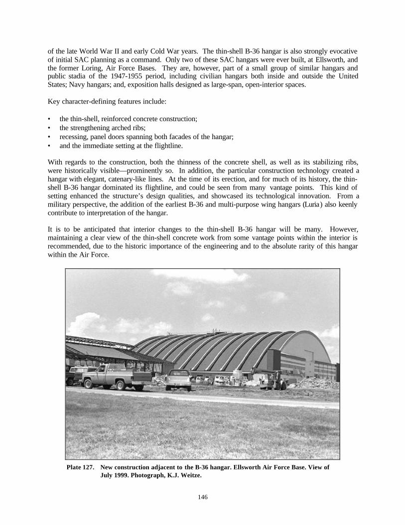
146
of the late World War II and early Cold War years. The thin-shell B-36 hangar is also strongly evocativeof initial SAC planning as a command. Only two of these SAC hangars were ever built, at Ellsworth, andthe former Loring, Air Force Bases. They are, however, part of a small group of similar hangars andpublic stadia of the 1947-1955 period, including civilian hangars both inside and outside the UnitedStates; Navy hangars; and, exposition halls designed as large-span, open-interior spaces.
Key character-defining features include:
• the thin-shell, reinforced concrete construction;• the strengthening arched ribs;• recessing, panel doors spanning both facades of the hangar;• and the immediate setting at the flightline.
With regards to the construction, both the thinness of the concrete shell, as well as its stabilizing ribs,were historically visible—prominently so. In addition, the particular construction technology created ahangar with elegant, catenary-like lines. At the time of its erection, and for much of its history, the thin-shell B-36 hangar dominated its flightline, and could be seen from many vantage points. This kind ofsetting enhanced the structure’s design qualities, and showcased its technological innovation. From amilitary perspective, the addition of the earliest B-36 and multi-purpose wing hangars (Luria) also keenlycontribute to interpretation of the hangar.
It is to be anticipated that interior changes to the thin-shell B-36 hangar will be many. However,maintaining a clear view of the thin-shell concrete work from some vantage points within the interior isrecommended, due to the historic importance of the engineering and to the absolute rarity of this hangarwithin the Air Force.
Plate 127. New construction adjacent to the B-36 hangar. Ellsworth Air Force Base. View ofJuly 1999. Photograph, K.J. Weitze.
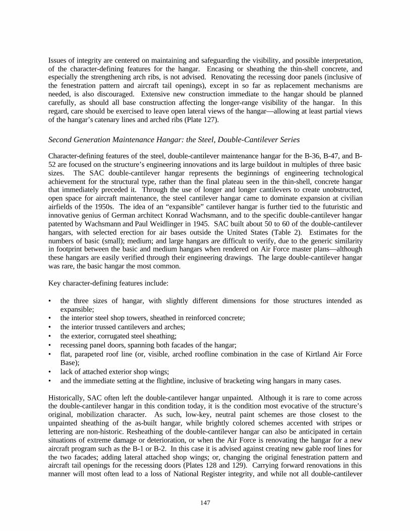
147
Issues of integrity are centered on maintaining and safeguarding the visibility, and possible interpretation,of the character-defining features for the hangar. Encasing or sheathing the thin-shell concrete, andespecially the strengthening arch ribs, is not advised. Renovating the recessing door panels (inclusive ofthe fenestration pattern and aircraft tail openings), except in so far as replacement mechanisms areneeded, is also discouraged. Extensive new construction immediate to the hangar should be plannedcarefully, as should all base construction affecting the longer-range visibility of the hangar. In thisregard, care should be exercised to leave open lateral views of the hangar—allowing at least partial viewsof the hangar’s catenary lines and arched ribs (Plate 127).
Second Generation Maintenance Hangar: the Steel, Double-Cantilever Series
Character-defining features of the steel, double-cantilever maintenance hangar for the B-36, B-47, and B-52 are focused on the structure’s engineering innovations and its large buildout in multiples of three basicsizes. The SAC double-cantilever hangar represents the beginnings of engineering technologicalachievement for the structural type, rather than the final plateau seen in the thin-shell, concrete hangarthat immediately preceded it. Through the use of longer and longer cantilevers to create unobstructed,open space for aircraft maintenance, the steel cantilever hangar came to dominate expansion at civilianairfields of the 1950s. The idea of an “expansible” cantilever hangar is further tied to the futuristic andinnovative genius of German architect Konrad Wachsmann, and to the specific double-cantilever hangarpatented by Wachsmann and Paul Weidlinger in 1945. SAC built about 50 to 60 of the double-cantileverhangars, with selected erection for air bases outside the United States (Table 2). Estimates for thenumbers of basic (small); medium; and large hangars are difficult to verify, due to the generic similarityin footprint between the basic and medium hangars when rendered on Air Force master plans—althoughthese hangars are easily verified through their engineering drawings. The large double-cantilever hangarwas rare, the basic hangar the most common.
Key character-defining features include:
• the three sizes of hangar, with slightly different dimensions for those structures intended asexpansible;
• the interior steel shop towers, sheathed in reinforced concrete;• the interior trussed cantilevers and arches;• the exterior, corrugated steel sheathing;• recessing panel doors, spanning both facades of the hangar;• flat, parapeted roof line (or, visible, arched roofline combination in the case of Kirtland Air Force
Base);• lack of attached exterior shop wings;• and the immediate setting at the flightline, inclusive of bracketing wing hangars in many cases.
Historically, SAC often left the double-cantilever hangar unpainted. Although it is rare to come acrossthe double-cantilever hangar in this condition today, it is the condition most evocative of the structure’soriginal, mobilization character. As such, low-key, neutral paint schemes are those closest to theunpainted sheathing of the as-built hangar, while brightly colored schemes accented with stripes orlettering are non-historic. Resheathing of the double-cantilever hangar can also be anticipated in certainsituations of extreme damage or deterioration, or when the Air Force is renovating the hangar for a newaircraft program such as the B-1 or B-2. In this case it is advised against creating new gable roof lines forthe two facades; adding lateral attached shop wings; or, changing the original fenestration pattern andaircraft tail openings for the recessing doors (Plates 128 and 129). Carrying forward renovations in thismanner will most often lead to a loss of National Register integrity, and while not all double-cantilever
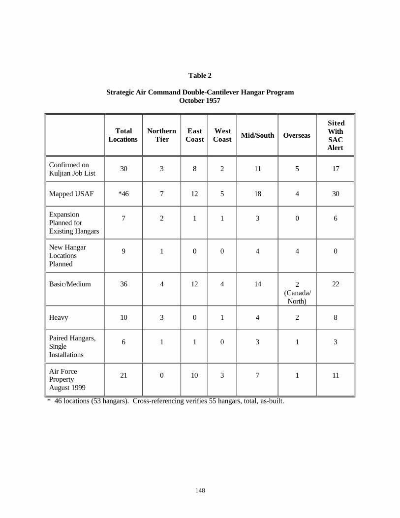
148
Table 2
Strategic Air Command Double-Cantilever Hangar ProgramOctober 1957
TotalLocations
NorthernTier
EastCoast
WestCoast Mid/South Overseas
SitedWithSACAlert
Confirmed onKuljian Job List
30 3 8 2 11 5 17
Mapped USAF *46 7 12 5 18 4 30
ExpansionPlanned forExisting Hangars
7 2 1 1 3 0 6
New HangarLocationsPlanned
9 1 0 0 4 4 0
Basic/Medium 36 4 12 4 14 2(Canada/North)
22
Heavy 10 3 0 1 4 2 8
Paired Hangars,SingleInstallations
6 1 1 0 3 1 3
Air ForcePropertyAugust 1999
21 0 10 3 7 1 11
* 46 locations (53 hangars). Cross-referencing verifies 55 hangars, total, as-built.
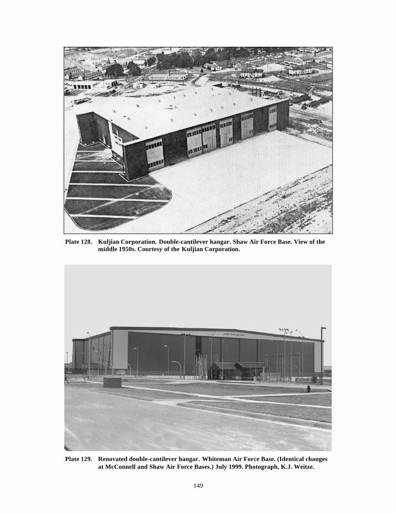
149
Plate 128. Kuljian Corporation. Double-cantilever hangar. Shaw Air Force Base. View of themiddle 1950s. Courtesy of the Kuljian Corporation.
Plate 129. Renovated double-cantilever hangar. Whiteman Air Force Base. (Identical changesat McConnell and Shaw Air Force Bases.) July 1999. Photograph, K.J. Weitze.
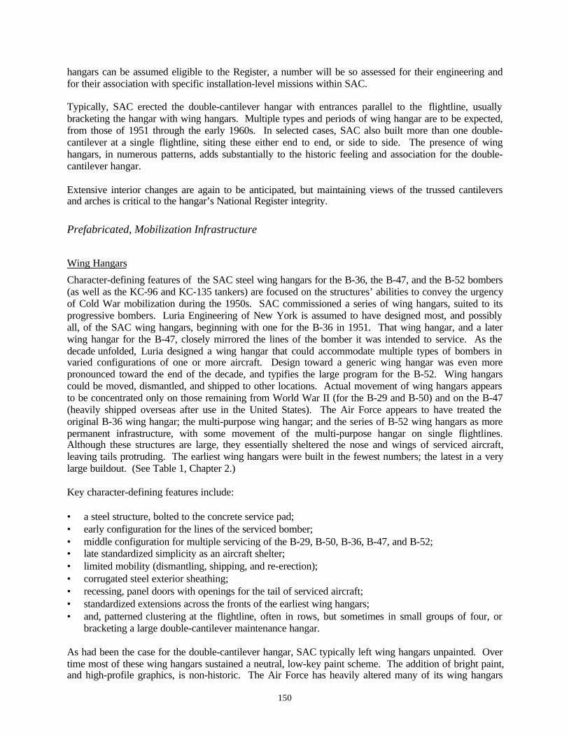
150
hangars can be assumed eligible to the Register, a number will be so assessed for their engineering andfor their association with specific installation-level missions within SAC.
Typically, SAC erected the double-cantilever hangar with entrances parallel to the flightline, usuallybracketing the hangar with wing hangars. Multiple types and periods of wing hangar are to be expected,from those of 1951 through the early 1960s. In selected cases, SAC also built more than one double-cantilever at a single flightline, siting these either end to end, or side to side. The presence of winghangars, in numerous patterns, adds substantially to the historic feeling and association for the double-cantilever hangar.
Extensive interior changes are again to be anticipated, but maintaining views of the trussed cantileversand arches is critical to the hangar’s National Register integrity.
Prefabricated, Mobilization Infrastructure
Wing Hangars
Character-defining features of the SAC steel wing hangars for the B-36, the B-47, and the B-52 bombers(as well as the KC-96 and KC-135 tankers) are focused on the structures’ abilities to convey the urgencyof Cold War mobilization during the 1950s. SAC commissioned a series of wing hangars, suited to itsprogressive bombers. Luria Engineering of New York is assumed to have designed most, and possiblyall, of the SAC wing hangars, beginning with one for the B-36 in 1951. That wing hangar, and a laterwing hangar for the B-47, closely mirrored the lines of the bomber it was intended to service. As thedecade unfolded, Luria designed a wing hangar that could accommodate multiple types of bombers invaried configurations of one or more aircraft. Design toward a generic wing hangar was even morepronounced toward the end of the decade, and typifies the large program for the B-52. Wing hangarscould be moved, dismantled, and shipped to other locations. Actual movement of wing hangars appearsto be concentrated only on those remaining from World War II (for the B-29 and B-50) and on the B-47(heavily shipped overseas after use in the United States). The Air Force appears to have treated theoriginal B-36 wing hangar; the multi-purpose wing hangar; and the series of B-52 wing hangars as morepermanent infrastructure, with some movement of the multi-purpose hangar on single flightlines.Although these structures are large, they essentially sheltered the nose and wings of serviced aircraft,leaving tails protruding. The earliest wing hangars were built in the fewest numbers; the latest in a verylarge buildout. (See Table 1, Chapter 2.)
Key character-defining features include:
• a steel structure, bolted to the concrete service pad;• early configuration for the lines of the serviced bomber;• middle configuration for multiple servicing of the B-29, B-50, B-36, B-47, and B-52;• late standardized simplicity as an aircraft shelter;• limited mobility (dismantling, shipping, and re-erection);• corrugated steel exterior sheathing;• recessing, panel doors with openings for the tail of serviced aircraft;• standardized extensions across the fronts of the earliest wing hangars;• and, patterned clustering at the flightline, often in rows, but sometimes in small groups of four, or
bracketing a large double-cantilever maintenance hangar.
As had been the case for the double-cantilever hangar, SAC typically left wing hangars unpainted. Overtime most of these wing hangars sustained a neutral, low-key paint scheme. The addition of bright paint,and high-profile graphics, is non-historic. The Air Force has heavily altered many of its wing hangars
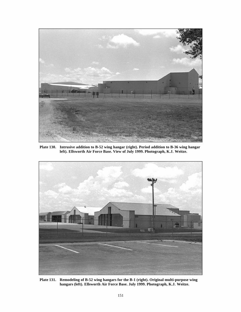
151
Plate 130. Intrusive addition to B-52 wing hangar (right). Period addition to B-36 wing hangarleft). Ellsworth Air Force Base. View of July 1999. Photograph, K.J. Weitze.
Plate 131. Remodeling of B-52 wing hangars for the B-1 (right). Original multi-purpose winghangars (left). Ellsworth Air Force Base. July 1999. Photograph, K.J. Weitze.

152
across the nation through later expansion. For the earliest B-36 and B-47 wing hangars, rarity is a majorissue. The presence of a B-36 or B-47 wing hangar, in an unaltered state, should be consideredexceptionally significant. Also of note, any surviving clusters of B-36 hangars with the Leo A. Dalyextensions of the middle 1950s are also very rare. In most of these cases—unless further additionsaccrued after 1955-1957—the additions should be interpreted as integral to integrity, not detracting fromit. By the buildout for the multi-purpose and B-52 wing hangars, the number of structures is much largeras is intrinsic design flexibility. In these cases, extensions and additions to the wing hangars detract fromintegrity substantially (Plates 130 and 131). Particularly important for interpretation of the SAC ColdWar hangar is its setting and association with other wing hangars. Clusters of wing hangars can beanticipated to be of like kind; or, layered over time at an installation; or, mixed (where moved, shippedfor a second-life use, or where pulled together from ad hoc sources during times of wing hangar scarcity).
The SAC wing hangar program was an exceptionally large one, and today is characterized by numbers ofaltered structures. Many wing hangars will not possess either individual integrity or their historicclustering, both supportive of any National Register consideration. However, in situations where largenumbers of unaltered, or minimally altered, wing hangars are extant, it is important to carefully addressthe potential for a National Register district or for cohesive rows / clusters.
Extensive interior changes are to be expected. Yet, due to the utilitarian nature of the wing hangar, it isequally likely that hangars will remain minimally altered, and may even possess their original steel false-floors—the latter placed at the front of the aircraft to allow bomber mechanics to work on aircraftengines.
SAC Airmen Dormitories
Character-defining features of the SAC airmen dormitories of the early 1950s are again focused on thestructures’ abilities to convey the urgency of Cold War mobilization, but are enhanced through theiradditional association with strong design tenants of the period. These structures offered quintessentialsteel-and-glass facades, and are linked to European modern architecture as it grew out of the Bauhaus andas it was showcased at the Museum of Modern Art in New York during the late 1930s. This level ofmodernism is relatively rare outside the skylines of major cities; university campuses; houses designedfor individual upscale clients; and, occasionally, schools. Here, the direct association between cutting-edge design, efficiency, mobilization, and a certain elite status for SAC airmen is intended, and can beinterpreted as deliberate on the part of SAC commander Curtis LeMay. The numbers of these steeldormitories, as-built, is unverified as yet, but appears to be a concentrated SAC phenomenon with a fewother Air Force applications. Survival of these dormitories, unaltered on their exteriors, is presumed to bevery rare, while renovation of interiors is a given. Their design in 1951 by SAC engineers themselves,using prefabricated steel paneling manufactured by the Detroit Steel Products Company, is also unusualfor Air Force design, and speaks to the very earliest years of the Cold War (Plate 132).
Key character-defining features include:
• completely steel structure;• insulated, steel Fenestra paneling;• steel detailing, such as stairwells, window frames, and doors;• expansive use of glass fenestration;• crisp design lines, including flat roof and minimal overhang;• and, construction in small groups of two and three units.

153
Plate 132. Remodeled SAC airmen dormitory. Original fenestration and entry (center).Ellsworth Air Force Base. View of July 1999. Photograph, K.J. Weitze.
SAC airmen dormitories are rare remnants of the bomber landscape. Known as constructed at Offutt(Nebraska), Ellsworth (South Dakota), and Pease Air Force Bases (New Hampshire), these structureswere likely proto-alert facilities when erected as a pair at the flightline, or isolated as a pair near it. Atthis time, only the SAC dormitories remaining at Ellsworth are within Air Force real property jurisdiction,although it is possible that dormitories of this type may exist at Lowry (Colorado) and Travis(California)—historically in more generalized use.
It is to be anticipated that both substantial exterior and interior remodeling will have occurred for thesestructures. Partial original exterior paneling and fenestration is present for three of the four dormitories atEllsworth, and suggests that, in at least one case, the original structure may be present in sections beneaththe remodeling.
Experimental Pavement
Experimental runway and apron pavements suitable for the very heavy bombers—particularly the B-36and the B-52—were a direct continuation of engineering undertaken during World War II. The debatefocused on the appropriateness of concrete versus asphaltic pavements. Comparable costs, speed ofconstruction, availability of materials, and permanence over time (while under heavy and abusive use bySAC bombers) were the key issues. Additionally, engineering for airfield pavements was tied tonecessary runway lengthenings and widenings; eroding shoulders; effects of engine blast and spilled jetfuel; high contact pressures before the availability of multiple-tire landing gear; very high landing speeds;and micro-climatic conditions. Some SAC installations sponsored pavement test tracks and sections.
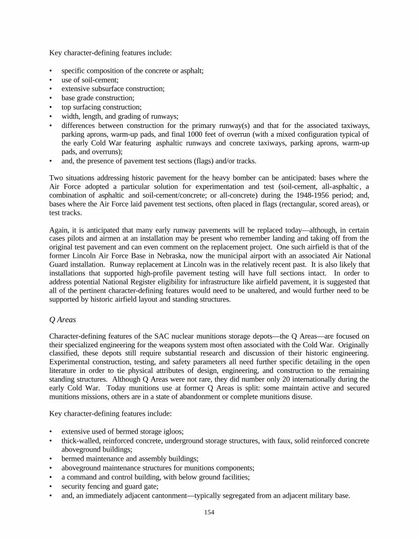
154
Key character-defining features include:
• specific composition of the concrete or asphalt;• use of soil-cement;• extensive subsurface construction;• base grade construction;• top surfacing construction;• width, length, and grading of runways;• differences between construction for the primary runway(s) and that for the associated taxiways,
parking aprons, warm-up pads, and final 1000 feet of overrun (with a mixed configuration typical ofthe early Cold War featuring asphaltic runways and concrete taxiways, parking aprons, warm-uppads, and overruns);
• and, the presence of pavement test sections (flags) and/or tracks.
Two situations addressing historic pavement for the heavy bomber can be anticipated: bases where theAir Force adopted a particular solution for experimentation and test (soil-cement, all-asphaltic , acombination of asphaltic and soil-cement/concrete; or all-concrete) during the 1948-1956 period; and,bases where the Air Force laid pavement test sections, often placed in flags (rectangular, scored areas), ortest tracks.
Again, it is anticipated that many early runway pavements will be replaced today—although, in certaincases pilots and airmen at an installation may be present who remember landing and taking off from theoriginal test pavement and can even comment on the replacement project. One such airfield is that of theformer Lincoln Air Force Base in Nebraska, now the municipal airport with an associated Air NationalGuard installation. Runway replacement at Lincoln was in the relatively recent past. It is also likely thatinstallations that supported high-profile pavement testing will have full sections intact. In order toaddress potential National Register eligibility for infrastructure like airfield pavement, it is suggested thatall of the pertinent character-defining features would need to be unaltered, and would further need to besupported by historic airfield layout and standing structures.
Q Areas
Character-defining features of the SAC nuclear munitions storage depots—the Q Areas—are focused ontheir specialized engineering for the weapons system most often associated with the Cold War. Originallyclassified, these depots still require substantial research and discussion of their historic engineering.Experimental construction, testing, and safety parameters all need further specific detailing in the openliterature in order to tie physical attributes of design, engineering, and construction to the remainingstanding structures. Although Q Areas were not rare, they did number only 20 internationally during theearly Cold War. Today munitions use at former Q Areas is split: some maintain active and securedmunitions missions, others are in a state of abandonment or complete munitions disuse.
Key character-defining features include:
• extensive used of bermed storage igloos;• thick-walled, reinforced concrete, underground storage structures, with faux, solid reinforced concrete
aboveground buildings;• bermed maintenance and assembly buildings;• aboveground maintenance structures for munitions components;• a command and control building, with below ground facilities;• security fencing and guard gate;• and, an immediately adjacent cantonment—typically segregated from an adjacent military base.

155
Q Areas do have individually significant structures within their boundaries. It is suggested that the Astructures (A-1 and A-2) are likely candidates for National Register eligibility, as are the Plants I and II(A and B), and the command post. For these structures, it will be important to ascertain the engineeringparameters for the thick-walled construction; any special concrete mix, use of reinforcing steel, orshielding; interior storage, maintenance, and assembly room layout; any physical features incorporated formunitions and personnel safety; and siting within the overall compound, both accommodating storagerequirements and alert. In addition, Register integrity would support the standard requirement that laterremodelings of these buildings within a Q Area not include such items as replacement of an early 1950sflat roof with a later one of gabled type, nor the removal of faux-fenestration or porches from the Astructures.
Alert Aprons and Moleholes
Character-defining features of the SAC alert apron configurations and crew quarters—moleholes—are arare instance where the features of the historic property include ones associated with both a standingstructure and an adjacent aircraft apron. Designed and engineered by Leo A. Daly, an Omaha firm alsoresponsible for SAC’s first and second generation underground command posts at Offutt Air Force Base,SAC alert facilities spread across the United States and into Canada. Design efforts began in the middle1950s, with buildout achieved during 1957-1960. The program followed hard upon a transitional alertinitiated by SAC in 1956, an alert using existing flightline dormitories and operations buildings, and onewhich acknowledged several different secured parking aprons. Not surprisingly, SAC undertookconstruction for its alert aprons first—and, again not surprisingly, design changed literally while apronswere in buildout. Resultant from this situation, two key alert apron patterns exist, supplemented byparticular instances where a pre-existing rectangular apron was called into service; a new rectangularapron and taxiway were built due to land limitations and topography; or, a former hot cargo area wasreconfigured for alert service. SAC also built alert aprons in different sizes—similar to its treatment ofthe double-cantilever hangar. Accompanying the alert aprons, and erected during 1958-1960, themoleholes also came in small, medium, and large sizes—and, like the alert aprons, occasionally werebuilt in a non-standard manner. Nonetheless, all SAC alert facilities had an alert apron and an alert crewquarters, the latter always basically designed as a molehole.
Key character-defining features include:
• an alert apron configured for between four and 10 bombers (B-47s, B-58s, and B-52s);• a taxiway angled at 45 degrees from the end of the primary (longest) runway;• and, a molehole of 18,000, 22,500, or 31,000 square feet.
In addition, the molehole had its own character-defining features, including:
• two-story height, with the lower story either fully below ground, or bermed aboveground;• egress tunnels from the underground story sheathed in corrugated metal with single-pane, wood-
frame windows per tunnel and blast-framed doors;• and, simple 1950s design detailing, including a nearly flat gable roof and windowless walls.
SAC alert facilities were secured areas, and so typically also had perimeter lighting and fencing at themolehole, with a manned checkpoint. Notably, SAC alert facilities did not have an associated cluster ofancillary structures, but were instead entirely self-contained. (ADC alert sustained an opposite characterat the flightline.) Buildout for the SAC alert program was 64 or 65 facilities, dependent on actualconstruction at Ramey Air Force Base in Puerto Rico (Table 3). Most SAC alert facilities had very shortactual lives, superceded by the emplacement of ICBMs; and by changing base priorities and assigned

156
Table 3
Strategic Air Command Flightline Alert
NorthernTier
EastCoast
WestCoast
Mid /South
Canada /North
PuertoRico
Total
Buildout 22 10 6 20 6 1 65
Christmas Tree Apron,Planned or In Place, October1957
11 7 1 6 0 0 25
90-degree Stub ApronPlanned or In Place, October1957
8 0 2 6 0 1 17
18,000 sf (70-man) 15 7 5 11 6 1 45
22,500 sf (100-man) 2 3 1 4 0 0 10
31,000 sf (150-man) 5 1 0 4 0 0 10
Began Construction 1958 13 9 1 3 6 0 32
Began Construction 1959 9 2 5 16 0 0 *32
Construction Complete byAugust 1959
5 4 0 0 0 0 9
Construction Complete byLate 1959
13 5 6 11 1 0 36
Construction Complete by1960
4 2 0 8 5 0 19
Air Force PropertyAugust 1999
7 7 4 5 0 1 (?) 24
* Ramey not under construction as of December 1959.
157
Plate 133. Heavily renovated molehole, with additions doubling square footage. Grand ForksAir Force Base. View of 1995. Courtesy of Geo-Marine, Inc.
aircraft. SAC placed both bombers and refueling tankers on alert, with a renewed alert period in themiddle 1960s. At that time, single installations sometimes supported both bombers and tankers on alert,with a generic, secured tanker apron often added at the flightline. The tanker alert of this period did nothave specially designed crew quarters, but rather used trailers or generic housing.
The SAC alert program was so large and widespread that remnants of its landscape can frequently befound well beyond current Air Force installations—at former bases that now function as municipal andcounty airfields in particular. Often it is at these locations that the least change has occurred, withmoleholes many times in use for local aero clubs. (Although in some cases, former moleholes are in anabandoned state, with security fencing still in place.) At active SAC bases, layered missions, newweapons systems, and the introduction of the B-1 all caused substantial loss of National Register integrityfor these 1950s alert facilities. In some cases, SAC renovated moleholes into barely recognizable“improved” quarters, typically increasing square footage by 100 percent (Plate 133). During the middle1970s and again with the B-1 in the middle 1980s, SAC also added perimeter structures at an activeformer molehole—family visitation quarters and other amenities far removed from the urgency of austerehigh alert. And, in some instances, SAC expanded the alert apron, following the original designconfiguration, but giving a false impression of the Cold War programmatic function of the facility.
Register integrity should adhere closely to the full complement of character-defining features for the SACalert facilities, and where a right-angled or herringbone (Christmas tree) alert apron is present, shouldinclude the apron as well. Removal of the corrugated egress tunnels, for example, is a substantial loss ofintegrity for this kind of simple, single-purpose structure. In addition, it is recommended that installation-specific history for SAC alert be addressed, before assuming eligibility. Even when integrity is present,alert mission may have been ephemeral. SAC alert facilities are significant primarily for their mission,not for their design or engineered structure.
158
SAC Command Post and Chapel
Command Post
The SAC command post, aboveground and below, at Offutt Air Force Base is a unique structure, and assuch is strongly tied to a mythic imagery for the command and its leader during the late 1940s and 1950s,Curtis LeMay. Command post character-defining features are focused on mission, design, andengineering. The aboveground structure is evocative of 1950s office design, generally, while theunderground structure is tied to the evolution of command posts in SAC’s sister command, ADC. Issuescentered on hardening; programmatic design for sustained alert; and command communications displayand linkage are similar to the same concerns within ADC for its air defense web of abovegroundcommand and control centers designed in 1949 (and built during 1951-1957) and its second and thirdgeneration Semi-Automatic Ground Environment (SAGE) and Backup Interceptor Control (BUIC)programs.
Key character-defining features include:
• 1950s aboveground office design;• below ground hardened construction;• tunnel egress from below ground compound to the aboveground office structure;• security and contamination safeguards for the underground compound;• and, programmatic design of the below ground situation displays and war room.
Integrity for the 1950s below ground command post is negligible today, with a second generation SACunderground command post built in the 1980s. Analysis of Register integrity for the later below groundcommand post, however, will address the same character-defining features, although can be anticipated tobe much more sophisticated in its engineering for hardening, contamination, and security.
Chapel
The SAC chapel is a second case where imagery for the command is uppermost. The 1950s exteriordesign by Leo A. Daly is typical for its period, and its associated issues of Register integrity relatedirectly to unaltered survival over time. Character definition for the chapel, however, is focused in itsfour large stained glass windows, presenting the Second, Eighth, Fifteenth, and Sixteenth Air Forceswithin SAC during the early Cold War, and, in its memorial window symbolizing the entire command.
Key character-defining features are not analyzed here, but should address the techniques used by the artistin creating the windows and the relationship of those techniques to stained glass craftsmanship of the late1950s and early 1960s.
Late Cold War Infrastructure
SAC infrastructure of the late Cold War is focused in the middle 1970s and again in the middle 1980s.With the exception of the second generation command post at Offutt Air Force Base, the buildings andstructures of this period pertinent to the B-1 and B-2 bomber mission are too recent, generally, to assessagainst criteria for the National Register. One hangar, that for the National Emergency AirborneCommand Post (NEACP), is visually very striking, and is likely deserving of further research andanalysis. Other work may follow.

159
Chapter 4: Real Property Management of Historic SAC Infrastructure
Following are one-page summaries, installation by installation, for adaptation to current Air CombatCommand (ACC) real property management. The summaries are brief, and are intended to correlateinformation present in the baseline inventories of 1995-1997 prepared by Mariah Associates, Inc., withthe context for SAC bomber infrastructure presented in chapter 2, and with the overview of character-defining features and National Register integrity presented in chapter 3. In a number of instances,information in the baseline studies is partial, with included photographs also not comprehensive.Nonetheless, the Mariah volumes do offer sufficient information to provide the guidelines given herein.In most cases, cultural resource managers at the installations should be able to fill in missing informationfor specific structures predicted to be present, and to complete (or revise) assessments of Registerintegrity. Fieldwork for the baseline inventories occurred four to five years ago, generally, and may needto be revisited by Air Force cultural resource managers for updating an assessment of integrity.
Addressed here are the installations under jurisdiction of ACC as of mid-1999 (Map 2). Those basesclosed or transferred to other Air Force commands since the Mariah inventories took place are notincluded in the real property summaries. Most of these installations do have comparable historicinfrastructure. Air Force real property managers for Air Mobility Command (AMC), Air Force ReserveCommand (AFRC), and Air Education and Training Command (AETC), may wish to review theinformation offered here—as well as that in chapters 2 and 3—for pertinence to installations under theirjurisdiction.
Current Continental United States (CONUS) ACC installations are those of Barksdale (Louisiana), Beale(California), Cannon (New Mexico), Davis-Monthan (Arizona), Dyess (Texas), Ellsworth (SouthDakota), Holloman (New Mexico), Langley (Virginia), Minot (North Dakota), Moody (Georgia),Mountain Home (Idaho), Nellis (Nevada), Offutt (Nebraska), Seymour Johnson (North Carolina), Shaw(South Carolina), and Whiteman (Missouri).
Installations included in the baseline Mariah study, but not included in the summaries that follow, areCastle (California: closed); Fairchild (Washington: ACC to AMC); Griffiss (New York: closed, with aportion to AFRC); Homestead (Florida: closed, with a portion to AFRC); Howard (Panama: transferringto the Government of Panama at the end of 1999); K.I. Sawyer (Michigan: closed); Little Rock(Arkansas: ACC to AETC); Loring (Maine: closed); MacDill (Florida: ACC to AMC); McConnell(Kansas: ACC to AMC); and Pope (North Carolina: ACC to AMC).
Information for each installation focuses on historic names; aircraft; missions; infrastructure; integrity;potential NRHP eligibility; and issues of note. Historic names for a base can be confusing forresearchers—so are provided here. Aircraft tell us what infrastructure an installation was likely to havehad: when the aircraft were received reflects the priority of the mission within SAC. (Are the assignedbombers ones that are being phased out? New inventory?) The remaining five items address realproperty management directly, and are self-explanatory. Summaries analyze only infrastructureassociated with the historic SAC bomber mission of the Cold War, as discussed in chapters 2 and 3.Many of the current ACC installations also host parallel historic ADC and TAC air defense infrastructureassociated with fighter, and, command and control missions. Air Force real property managers areencouraged to cross reference information presented in this chapter with that offered in chapter 4 of thecompanion volume, Cold War Infrastructure for Air Defense: The Fighter and Command Missions.

160
Map
2.
CO
NU
S A
ir C
omba
t C
omm
and
Inst
alla
tion
sC
urre
nt a
s of
Aug
ust
1999
.
BE
AL
E
MO
UN
TAIN
HO
ME
MIN
OT
EL
LS
WO
RT
H
OF
FU
TT
WH
ITE
MA
N
CA
NN
ON
BA
RK
SD
AL
ED
YE
SS
HO
LL
OM
AN
SH
AW
MO
OD
Y
SE
YM
OU
R J
OH
NS
ON
LA
NG
LE
Y
DA
VIS
-M
ON
TH
AN
NE
LL
IS
Not
to S
cale
161
Barksdale Air Force BaseVicinity of Bossier City, and, Shreveport, Louisiana
Information based upon photographs and text in A Baseline Inventory of Cold War Material Culture atBarksdale Air Force Base, volume II-1 of A Systemic Study of Air Combat Command Cold War MaterialCulture (July 1997)
Historic Names: Barksdale Field (1933-1947)Barksdale Air Force Base (1948 to present)
Cold War Bomber and Tanker Aircraft: B-26 (close of World War II into the early Cold War)B-45 (1949; phased out after 1954)B-47 (1954; phased out after 1958)KC-97 (accompanied the B-47)B-52 (received 1958)KC-135 (received 1958)KC-10 (received 1981)
Missions: Headquarters Second Air Force, SACAFSWP Q Area – Main StockpileSAC Bomber and Tanker AlertSAC Airborne Alert Exercises – Chrome DomePost-Attack Command Control System (PACCS)[Looking Glass: Auxiliary Command Post]U-2 Reconnaissance
Infrastructure: Bossier Base [Q Area]Molehole and Christmas Tree Alert Apron (small)Tanker Alert (late added crew quarters and apron)PACCS SheltersU-2 HangarsMedium Aircraft (B-52) Wing Hangars
Integrity: Bossier Base: highMolehole and Christmas Tree Alert Apron: lostPACCS Shelters: unassessedU-2 Hangars / Shelters: unassessedMedium Aircraft Wing Hangars: unassessed
Potential NRHP Eligibility: Bossier Base: A-1 / A-2; command post; Plants I and IIMolehole / Christmas Tree: none (heavily modified)Tanker Alert: none (generic late infrastructure)PACCS: potential use of B-52 wing hangars,
unassessedU-2 Hangars / Shelters: unassessedMedium Aircraft Wing Hangars: unassessed
Other: Barksdale supported SAC alert crew trailers in 1958.None of these trailers are known to exist today.If discovered on base, they should be assessed.

162
Beale Air Force BaseVicinity of Wheatland, Marysville, and Yuba City, California
Information based upon photographs and text in A Baseline Inventory of Cold War Material Culture atBeale Air Force Base, volume II-2 of A Systemic Study of Air Combat Command Cold War MaterialCulture (October 1997).
Historic Names: Camp Beale (1942-1947)Beale Air Force Range (1948-1951)Beale Air Force Base (1951 to present)
Cold War Bomber and Tanker Aircraft: KC-135 (received 1959)B-52 (received 1960)
Missions: SAC Bomber and Tanker AlertSR-71 ReconnaissanceU-2 ReconnaissanceTR-1 Reconnaissance
Infrastructure: Molehole and Right-Angle Stub Alert Apron (small)SR-71 Butler HangarsU-2 HangarsTR-1 HangarsMedium Aircraft (B-52) Wing Hangars
Integrity: Molehole and Alert Apron: lostSR-71 Hangars: intactU-2 Hangars / Shelters: unassessedTR-1 Hangars: intactMedium Aircraft Wing Hangars: unassessed
Potential NRHP Eligibility: Molehole and Alert Apron: noneSR-71 Hangars: possibleU-2 Hangars / Shelters: unassessedTR-1 Hangars: late prefabricated structures, unlikelyMedium Aircraft Wing Hangars: here without
double-cantilever hangar, unlikely
Other: No issues.

163
Cannon Air Force BaseVicinity of Clovis, New Mexico
Information based upon photographs and text in A Baseline Inventory of Cold War Material Culture atCannon Air Force Base, volume II-3 of A Systemic Study of Air Combat Command Cold War MaterialCulture (June 1997).
Historic Names: Portair Field (1920s)Clovis Municipal Airport (1930s)Clovis Army Air Field (1942-1947)Clovis Air Force Base (1947)[Deactivated 1947-1950]Clovis Air Force Base (1950-1957)Cannon Air Force Base (1957 to present)
Cold War Bomber and Tanker Aircraft: B-17 (1946-1947)B-24 (1946-1947)B-29 (1946-1947)
Missions: Training aircrews for the B-17, B-24, and B-29
Infrastructure: None extant
Integrity: N/A
Potential NRHP Eligibility: N/A
Other: No issues.

164
Davis-Monthan Air Force BaseVicinity of Tucson, Arizona
Information based upon photographs and text in A Baseline Inventory of Cold War Material Culture atDavis-Monthan Air Force Base, volume II-5 of A Systemic Study of Air Combat Command Cold WarMaterial Culture (July 1997).
Historic Names: Davis-Monthan Field (1927-1940)Tucson Air Base (1941)Davis-Monthan Field (1941-1947)Davis-Monthan Air Force Base (1948 to present)
Cold War Bomber and Tanker Aircraft: B-29 (1946-1953)B-50 (1948-1953)KB-29 (1948-1953)B-47 (1953-1964)KC-97 (received 1953-1954)
Missions: Extended Aircraft StorageSAC Bomber AlertU-2 Reconnaissance
Infrastructure: Molehole and Christmas Tree Alert Apron (medium)U-2 Hangars / Shelters [medium aircraft wing hangars]
Integrity: Molehole and Alert Apron: lostU-2 Hangars / Shelters: intact
Potential NRHP Eligibility: Molehole and Alert Apron: noneU-2 Hangars / Shelters: unassessed
Other: No issues.
165
Dyess Air Force BaseVicinity of Abilene, Texas
Information based upon photographs and text in A Baseline Inventory of Cold War Material Culture atDyess Air Force Base, volume II-6 of A Systemic Study of Air Combat Command Cold War MaterialCulture (June 1997).
Historic Names: Tye Army Air Field (1942)Abilene Army Air Field (1943-1947)[Deactivated 1947-1952]Abilene Air Force Base (1953-1955)Dyess Air Force Base (1956 to present)
Cold War Bomber and Tanker Aircraft: B-47 (1955-1963)KC-97 (received 1955)B-52 (1963/1965-1985)KC-135 (received 1963-1965)B-1 (received 1985)
Missions: SAC Bomber AlertB-1
Infrastructure: Double-Cantilever Maintenance Hangars (2)(basic and medium)
Miscellaneous Wing HangarsMedium Aircraft (B-52) Wing HangarsMolehole and (ad hoc) Rectangular Alert ApronB-1 Maintenance Dock and Fuel Cell Dock
Integrity: Double-Cantilever Hangars: intact / minormodification
Miscellaneous Wing Hangars: unassessedMedium Aircraft Wing Hangars: intact and unassessedMolehole and Alert Apron: lostB-1 Maintenance and Fuel Cell Docks: intact
Potential NRHP Eligibility: Double-Cantilever Hangars: unlikelyMiscellaneous Wing Hangars: unlikelyMedium Aircraft Wing Hangars: unlikelyMolehole and Alert Apron: noneB-1 Maintenance and Fuel Cell Docks: possible
Other: Dyess supports a varied group of wing hangars,including two with footprints of B-29 type. It isassumed that most of the group are altered, but noreal inventory assessment exists.
166
Ellsworth Air Force BaseVicinity of Rapid City, South Dakota
Information based upon photographs and text in A Baseline Inventory of Cold War Material Culture atEllsworth Air Force Base, volume II-7 of A Systemic Study of Air Combat Command Cold War MaterialCulture (August 1997).
Historic Names: Rapid City Army Air Base (1942-1946)[Deactivated 1946-1947]Rapid City Air Force Base (1947)Weaver Air Force Base (1948)Rapid City Air Force Base (1948-1953)Ellsworth Air Force Base (1953 to present)
Cold War Bomber and Tanker Aircraft: B-29 (received 1947)B-36 (1949-1957)B-52 (received 1957)KC-135 (received 1959)EC-135 (received 1965)B-1 (received 1986)
Missions: B-36 ReconnaissanceAFSWP Q Area - Alert Avia tion Depot SquadronSAC Bomber AlertPACCS [Looking Glass: Auxiliary Command Post]B-1B
Infrastructure: Thin-Shell, Concrete Maintenance HangarB-36 Wing HangarsSAC Steel Airmen Dormitories (4)Rushmore Air Force Station (AFS) [Q Area]Multi-Purpose and B-52 Wing HangarsMolehole and Christmas Tree Alert Apron (small)
Integrity: Thin-Shell, Concrete Maintenance Hangar: intactB-36 Wing Hangars: early minor addition, intactSAC Dormitories: lostRushmore AFS: mixedMulti-Purpose and B-52 Wing Hangars: mixedMolehole / Alert Apron: unassessed / lost
Potential NRHP Eligibility: Thin-Shell, Concrete Maintenance Hangar: strongB-36 Wing Hangars: strongSAC Dormitories: noneRushmore AFS (Q Area): possible structuresMulti-Purpose and B-52 Wing Hangars: unlikelyMolehole and Alert Apron: unlikely
Other: Drawings in the civil engineering vault for the thin-shell, concrete maintenance hangar; the SACairmen dormitories; and the B-36 wing hangars arequite rare.
167
Holloman Air Force BaseVicinity of Alamogordo, New Mexico
Information based upon photographs and text in A Baseline Inventory of Cold War Material Culture atHolloman Air Force Base, volume II-10 of A Systemic Study of Air Combat Command Cold War MaterialCulture (October 1997).
Historic Names: Alamogordo Bombing and Gunnery Range (1941)Alamogordo Army Air Field (1941-1946)[Deactivated 1946, briefly]Alamogordo Army Air Field (1946)Alamogordo Air Force Base (1947-1948)Holloman Air Force Base (1948 to present)
Cold War Bomber and Tanker Aircraft: None
Missions: No Cold War bomber missions
Infrastructure: No SAC infrastructure
Integrity: N/A
Potential NRHP Eligibility: N/A
Other: No issues.

168
Langley Air Force BaseVicinity of Hampton, Virginia
Information based upon photographs and text in A Baseline Inventory of Cold War Material Culture atLangley Air Force Base, volume II-14 of A Systemic Study of Air Combat Command Cold War MaterialCulture (August 1997).
Historic Names: Langley Field (1915-1947)Langley Air Force Base (1948 to present)
Cold War Bomber and Tanker Aircraft: B-26 (received 1950)B-45 (received 1951)KB-50 (received 1958)
Missions: TAC Fighter-Bomber Training and Support
Infrastructure: Double-Cantilever Hangar (basic)Fuel Systems Maintenance Docks (5)
Integrity: Double-Cantilever Hangar: intactFuel Systems Maintenance Docks: unassessed
Potential NRHP Eligibility: Double-Cantilever Hangar: possibleFuel Systems Maintenance Docks: unlikely
Other: Relatively rare instance of a double-cantileverhangar built at a TAC installation: for use by fighterand small bomber aircraft.

169
Minot Air Force BaseVicinity of Minot, North Dakota
Information based upon photographs and text in A Baseline Inventory of Cold War Material Culture atMinot Air Force Base, volume II-19 of A Systemic Study of Air Combat Command Cold War MaterialCulture (August 1997).
Historic Names: Minot Air Force Base (1957 to date)
Cold War Bomber and Tanker Aircraft: KC-135 (received 1959)B-52H (received 1961)
Missions: SAC Tanker and Bomber Alert
Infrastructure: Molehole and Christmas Tree Alert Apron (small)Medium Aircraft (B-52) Wing Hangars (4)Miscellaneous Wing Hangars (2)Tanker Pen with Crew Quarters (late addition)Late Cold War Large Aircraft Maintenance Dock
Integrity: Molehole and Original Alert Apron: lostTanker Pen with Crew Quarters: intactWing Hangars: unassessedLarge Aircraft Maintenance Dock: intact
Potential NRHP Eligibility: Molehole / Alert Apron: noneTanker Pen with Crew Quarters: none (generic)Wing Hangars: unlikelyLarge Aircraft Maintenance Dock: unlikely
Other: No issues.
170
Moody Air Force BaseVicinity of Valdosta, Georgia
Information based upon photographs and text in A Baseline Inventory of Cold War Material Culture atMoody Air Force Base, volume II-20 of A Systemic Study of Air Combat Command Cold War MaterialCulture (July 1997).
Historic Names: Moody Field (1941-1946)[Deactivated 1946-1951]Moody Air Force Base (1951 to present)
Cold War Bomber and Tanker Aircraft: None
Missions: No Cold War bomber missions
Infrastructure: No SAC infrastructure
Integrity: N/A
Potential NRHP Eligibility: N/A
Other: No issues.

171
Mountain Home Air Force BaseVicinity of Mountain Home, Idaho
Information based upon photographs and text in A Baseline Inventory of Cold War Material Culture atMountain Home Air Force Base, volume II-21 of A Systemic Study of Air Combat Command Cold WarMaterial Culture (July 1997).
Historic Names: Mountain Home Army Air Base (1942-1943)Mountain Home Army Air Field (1943-1945)[Deactivated 1945-1947]Mountain Home Air Force Base (1948-1949)[Deactivated 1949-1951]Mountain Home Air Force Base (1951 to present)
Cold War Bomber and Tanker Aircraft: B-29 (received 1953)KB-29 (received 1953)B-47 (1954-1966)KC-97 (1954-1966)B-52G (1992-1994)KC-135 (received 1992)B-1 (received 1994)
Missions: SAC Bomber Alert
Infrastructure: Multi-Purpose Wing Hangars (5)Molehole (large) and Christmas Tree Alert Aprons(1 ½)
Integrity: Multi-Purpose Wing Hangars: mixedMolehole and Alert Apron: intact
Potential NRHP Eligibility: Multi-Purpose Wing Hangars: unlikelyMolehole and Alert Apron: strong
Other: No issues.

172
Nellis Air Force BaseVicinity of Las Vegas, Nevada
Information based upon photographs and text in A Baseline Inventory of Cold War Material Culture atNellis Air Force Base, volume II-22 of A Systemic Study of Air Combat Command Cold War MaterialCulture (August 1997).
Historic Names: Western Air Express Airfield (1926-1941)Las Vegas Airfield (1941)McCarran Field (1941)Las Vegas Army Gunnery School (1942)Las Vegas Army Air Field (1943-1947)[Deactivated 1947-1948]Las Vegas Air Force Base (1949-1950)Nellis Air Force Base (1950 to present)
Cold War Bomber and Tanker Aircraft: None
Missions: No Cold War bomber missions
Infrastructure: No SAC infrastructure
Integrity: N/A
Potential NRHP Eligibility: N/A
Other: No issues.

173
Offutt Air Force BaseVicinity of Bellevue and Omaha, Nebraska
Information based upon photographs and text in A Baseline Inventory of Cold War Material Culture atOffutt Air Force Base, volume II-23 of A Systemic Study of Air Combat Command Cold War MaterialCulture (October 1997).
Historic Names: Fort Crook (1888-1946)Offutt Field (1924-1947)Offutt Air Force Base (1948 to present)
Cold War Bomber and Tanker Aircraft: EC-135 (received 1959)E-4B (received 1974)
Missions: SAC HeadquartersPACCS (Looking Glass: Command Post)National Emergency Airborne Command Post(NEACP)
Infrastructure: 1st SAC Headquarters under LeMay (A Building)SAC Airmen Dormitories2nd SAC Headquarters (Western Pentagon)1st SAC Underground Command PostSAC ChapelPACCSNEACP2nd SAC Underground Command Post
Integrity: 1st SAC Headquarters: intact (exterior)SAC Airmen Dormitories: lost2nd SAC Headquarters: intact (exterior)1st SAC Underground Command Post: unassessedSAC Chapel: intactPACCS: intactNEACP: intact2nd SAC Underground Command Post: intact
Potential NRHP Eligibility: 1st SAC Headquarters: strongSAC Airmen Dormitories: none2nd SAC Headquarters: strong1st SAC Underground Command Post: unassessedSAC Chapel: strongPACCS: strongNEACP: strong2nd SAC Underground Command Post: strong
Other: Selected drawings held in the civil engineering vaultare rare.

174
Seymour Johnson Air Force BaseVicinity of Goldsboro, North Carolina
Information based upon photographs and text in A Baseline Inventory of Cold War Material Culture atSeymour Johnson Air Force Base, volume II-26 of A Systemic Study of Air Combat Command Cold WarMaterial Culture (July 1997).
Historic Names: Seymour Johnson Field (1941-1946)[Deactivated 1946-1949]Seymour Johnson Field (Municipal Airport: 1949-
1952)Seymour Johnson Air Force Base (1953 to present)
Cold War Bomber and Tanker Aircraft: B-52 (1959-1982)KC-135 (1959-1985)KC-10 (1985-1994)
Missions: SAC Bomber Alert
Infrastructure: Double-Cantilever Hangar (basic)B-47 Wing HangarMulti-Purpose Wing HangarMedium Aircraft (B-52) Wing HangarMolehole / Christmas Tree Alert Apron (small)
Integrity: Double-Cantilever Hangar: intactB-47 Wing Hangar: unassessedMulti-Purpose Wing Hangar: intactMedium Aircraft Wing Hangar: intactMolehole [bermed] / Alert Apron: intact
Potential NRHP Eligibility: Double-Cantilever Hangar: possibleWing Hangars: possibleMolehole / Alert Apron: strong
Other: Seymour Johnson hosts an unusual collection ofthree different wing hangars. The Air Force likely assigned these hangars in this manner due to ageneral shortage of infrastructure during the middle1950s. Noteworthy here is the presence of a B-47wing hangar, Building No. 4828, now very, very rare.
In addition, Seymour Johnson’s molehole is builtaboveground, bermed for the protection typicallyachieved by building the first story as a basement.Only a small number of moleholes were erected inthis manner.

175
Shaw Air Force BaseVicinity of Sumter, South Carolina
Information based upon photographs and text in A Baseline Inventory of Cold War Material Culture atShaw Air Force Base, volume II-25 of A Systemic Study of Air Combat Command Cold War MaterialCulture (July 1997).
Historic Names: Shaw Army Air Field (1941-1947)Shaw Air Force Base (1948 to present)
Cold War Bomber and Tanker Aircraft: RB-26 (1951-1954)RB-57A (1954-1956)RB-66 (1956 into the 1970s)
Missions: TAC Fighter-Bomber ReconnaissanceAir Force Advanced School for Tactical
Reconnaissance
Infrastructure: Double-Cantilever Maintenance Hangar (medium)
Integrity: Double-Cantilever Maintenance Hangar: lost
Potential NRHP Eligibility: Double-Cantilever Maintenance Hangar: none
Other: Atypical use of a double-cantilever hangar for TACfighter-bomber missions.

176
Whiteman Air Force BaseVicinity of Knob Noster, Missouri
Information based upon photographs and text in A Baseline Inventory of Cold War Material Culture atWhiteman Air Force Base, volume II-27 of A Systemic Study of Air Combat Command Cold WarMaterial Culture (August 1997).
Historic Names: Sedalia Army Air Field (1942-1946)[Deactivated 1946-1951]Sedalia Air Force Base (1951-1955)Whiteman Air Force Base (1955 to present)
Cold War Bomber and Tanker Aircraft: B-47 (1954-1963)KC-97 (1954-1963)B-58 (1969)KC-135A (1969-1970)B-2 (1988)
Missions: SAC Bomber AlertB-2
Infrastructure: Molehole (large) and ad hoc Rectangular AlertApron
Multi-Purpose Wing HangarB-2 Shelters
Integrity: Molehole / Apron: intactMulti-Purpose Wing Hangar: intactB-2 Shelters: intact
Potential NRHP Eligibility: Molehole / Apron: strongMulti-Purpose Wing Hangar: unlikelyB-2 Shelters: unlikely (generic infrastructure)
Other: The molehole at Whiteman is one of a small numberof 150-man crew quarters built by SAC, and sustainsa high degree of exterior integrity. It is furtherunusual with its ad hoc rectangular apron.
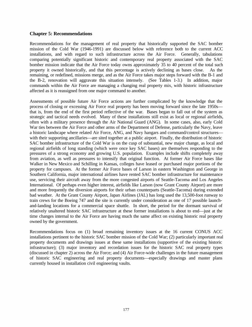
177
Chapter 5: Recommendations
Recommendations for the management of real property that historically supported the SAC bombermission of the Cold War (1946-1991) are discussed below with reference both to the current ACCinstallations, and with regard to such infrastructure across the Air Force. Generally, tabulationscomparing potentially significant historic and contemporary real property associated with the SACbomber mission indicate that the Air Force today owns approximately 35 to 40 percent of the total suchproperty it owned historically, and that this percentage is actively declining as bases close. As theremaining, or redefined, missions merge, and as the Air Force takes major steps forward with the B-1 andthe B-2, renovation will aggravate this situation intensely. (See Tables 1-3.) In addition, majorcommands within the Air Force are managing a changing real property mix, with historic infrastructureaffected as it is reassigned from one major command to another.
Assessments of possible future Air Force actions are further complicated by the knowledge that theprocess of closing or excessing Air Force real property has been moving forward since the late 1950s—that is, from the end of the first period reflective of the war. Bases began to fall out of the system asstrategic and tactical needs evolved. Many of these installations still exist as local or regional airfields,often with a military presence through the Air National Guard (ANG). In some cases, also, early ColdWar ties between the Air Force and other arms of the Department of Defense, particularly the Navy, leavea historic landscape where related Air Force, ANG, and Navy hangars and command/control structures—with their supporting ancillaries—are sited together at a public airport. Finally, the distribution of historicSAC bomber infrastructure of the Cold War is on the cusp of substantial, new major change, as local andregional airfields of long standing (which were once key SAC bases) are themselves responding to thepressures of a strong economy and growing U.S. population. Examples include shifts completely awayfrom aviation, as well as pressures to intensify that original function. At former Air Force bases likeWalker in New Mexico and Schilling in Kansas, colleges have leased or purchased major portions of theproperty for campuses. At the former Air Force bases of Larson in eastern Washington and George inSouthern California, major international airlines have rented SAC bomber infrastructure for maintenanceuse, servicing their aircraft away from the more congested airports of Seattle-Tacoma and Los AngelesInternational. Of perhaps even higher interest, airfields like Larson (now Grant County Airport) are moreand more frequently the diversion airports for their urban counterparts (Seattle-Tacoma) during extendedbad weather. At the Grant County Airport, Japan Airlines (JAL) has long used the 13,500-foot runway totrain crews for the Boeing 747 and the site is currently under consideration as one of 17 possible launch-and-landing locations for a commercial space shuttle. In short, the period for the dormant survival ofrelatively unaltered historic SAC infrastructure at these former installations is about to end—just at thetime changes internal to the Air Force are having much the same affect on existing historic real propertyowned by the government.
Recommendations focus on (1) broad remaining inventory issues at the 16 current CONUS ACCinstallations pertinent to the historic SAC bomber mission of the Cold War; (2) particularly important realproperty documents and drawings issues at these same installations (supportive of the existing historicinfrastructure); (3) major inventory and recordation issues for the historic SAC real property types(discussed in chapter 2) across the Air Force; and (4) Air Force-wide challenges in the future managementof historic SAC engineering and real property documents—especially drawings and master planscurrently housed in installation civil engineering vaults.
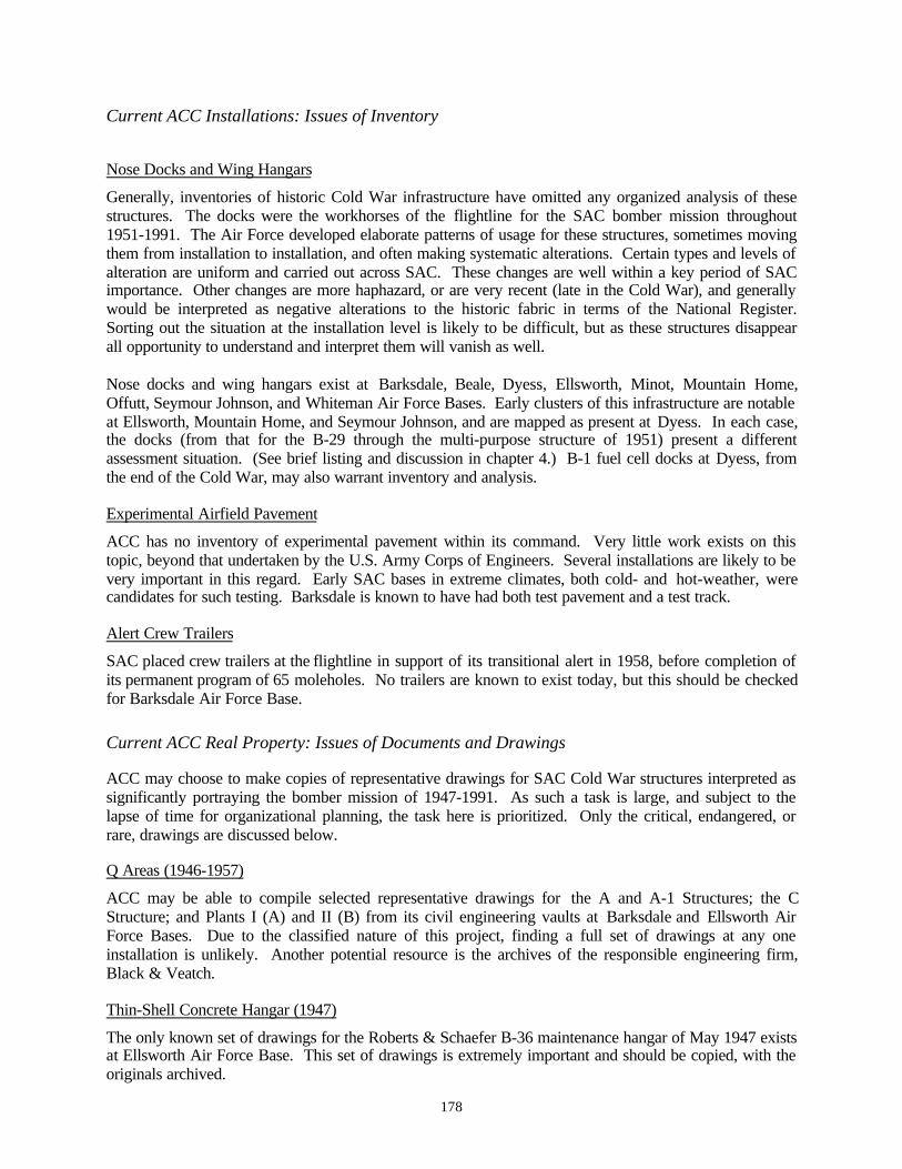
178
Current ACC Installations: Issues of Inventory
Nose Docks and Wing Hangars
Generally, inventories of historic Cold War infrastructure have omitted any organized analysis of thesestructures. The docks were the workhorses of the flightline for the SAC bomber mission throughout1951-1991. The Air Force developed elaborate patterns of usage for these structures, sometimes movingthem from installation to installation, and often making systematic alterations. Certain types and levels ofalteration are uniform and carried out across SAC. These changes are well within a key period of SACimportance. Other changes are more haphazard, or are very recent (late in the Cold War), and generallywould be interpreted as negative alterations to the historic fabric in terms of the National Register.Sorting out the situation at the installation level is likely to be difficult, but as these structures disappearall opportunity to understand and interpret them will vanish as well.
Nose docks and wing hangars exist at Barksdale, Beale, Dyess, Ellsworth, Minot, Mountain Home,Offutt, Seymour Johnson, and Whiteman Air Force Bases. Early clusters of this infrastructure are notableat Ellsworth, Mountain Home, and Seymour Johnson, and are mapped as present at Dyess. In each case,the docks (from that for the B-29 through the multi-purpose structure of 1951) present a differentassessment situation. (See brief listing and discussion in chapter 4.) B-1 fuel cell docks at Dyess, fromthe end of the Cold War, may also warrant inventory and analysis.
Experimental Airfield Pavement
ACC has no inventory of experimental pavement within its command. Very little work exists on thistopic, beyond that undertaken by the U.S. Army Corps of Engineers. Several installations are likely to bevery important in this regard. Early SAC bases in extreme climates, both cold- and hot-weather, werecandidates for such testing. Barksdale is known to have had both test pavement and a test track.
Alert Crew Trailers
SAC placed crew trailers at the flightline in support of its transitional alert in 1958, before completion ofits permanent program of 65 moleholes. No trailers are known to exist today, but this should be checkedfor Barksdale Air Force Base.
Current ACC Real Property: Issues of Documents and Drawings
ACC may choose to make copies of representative drawings for SAC Cold War structures interpreted assignificantly portraying the bomber mission of 1947-1991. As such a task is large, and subject to thelapse of time for organizational planning, the task here is prioritized. Only the critical, endangered, orrare, drawings are discussed below.
Q Areas (1946-1957)
ACC may be able to compile selected representative drawings for the A and A-1 Structures; the CStructure; and Plants I (A) and II (B) from its civil engineering vaults at Barksdale and Ellsworth AirForce Bases. Due to the classified nature of this project, finding a full set of drawings at any oneinstallation is unlikely. Another potential resource is the archives of the responsible engineering firm,Black & Veatch.
Thin-Shell Concrete Hangar (1947)
The only known set of drawings for the Roberts & Schaefer B-36 maintenance hangar of May 1947 existsat Ellsworth Air Force Base. This set of drawings is extremely important and should be copied, with theoriginals archived.
179
Nose Docks and Wing Hangars (1951-1956)
Sequencing for the series of drawings representing nose docks and wing hangars is especially complex,1951-1956. The earliest Cold War docks are those of Luria for the B-36, followed by the firm’sexecution for the multi-purpose wing hangar (both in 1951). Missing to date is the drawing series for theB-47 dock. During the middle 1950s, several important engineering firms, including Strobel & Salzmanand Kuljian, also executed revisions for the Luria multi-purpose wing hangar—each with a set ofdrawings. Both full and partial sets of wing hangar drawings, from 1951 through 1956, should bereviewed in the installation civil engineering vaults where they still exist, with copies made to compile acomplete representative set across bases holding respective individual drawings.
Installations likely to have full or partial sets of such drawings include Dyess, Ellsworth, MountainHome, Seymour Johnson, and Whiteman. Such drawings are confirmed at Ellsworth and Whiteman.Notable also: Seymour Johnson has a standing B-47 dock, and may have a set of its drawings.
Double-Cantilever Hangar (1951)
Although excellent representation exists for the Kuljian double-cantilever hangar in its full configurationas basic, medium, and heavy, including expansible, it would be prudent to make full-sized copies for eachversion of the hangar through available sets of drawings held at the installation level. One set of originalsshould be archived.
Installations likely to have full or partial sets of double-cantilever drawings include Barksdale, Dyess,Langley, Seymour Johnson, and Shaw. The Air Force has modified the hangar at Whiteman, with theoriginal drawings no longer extant.
SAC Airmen Dormitories (1951)
Drawings for the Detroit Steel Products Company SAC airmen dormitories are rare. ACC is advised tocompile a partial or full set of these drawings from available originals at Ellsworth Air Force Base.Drawings for the dormitories at Offutt Air Force Base no longer exist.
Moleholes (1958-1960)
A complete set of the standardized drawings for the Leo A. Daly SAC alert crew quarters, the moleholes,should also be compiled across three or more bases having a 70-man, 100-man, and 150-man structure.Additionally, where SAC built a molehole aboveground, using berming to shield the lower story, site-adaptation drawings should be reproduced to augment the representative 70-, 100-, and 150-man set.
ACC installations likely to have the appropriate drawings are Barksdale, Beale, Ellsworth, and Minot [70-man molehole]; Davis-Monthan [100-man molehole]; Mountain Home and Whiteman [150-manmolehole]; and, Seymour Johnson [bermed 70-man molehole].
Air Force-Wide: Issues of Inventory and Recordation Across Real Property Types
A much more comprehensive issue exists addressing the most effective method of inventorying, and insome cases recording, the best examples of the key SAC real property types associated with thecommand’s Cold War bomber mission. In many cases, the best solution may be to look at a propertytype—such as the double-cantilever hangar or the molehole—and assess what is significant about itsbuildout program as a whole. From this point, one can then address where the likely examples are; wherethey may remain in a least altered state; where they were supported by apron and flightline configurationshistorically; and where there existed with special site adaptations. It may also be pertinent to assess theearliest built within the overall program, and those associated with critical and/or extended Cold Warmissions.

180
In this regard, the key structures for the SAC bomber mission are:
the double-cantilever hangar;the B-36, B-47, and multi-purpose wing hangars;the SAC airmen steel-panel dormitory;selected experimental pavement and test sections / tracks;Q Areas; and, moleholes and accompanying alert aprons.For these six property types, some level of more comprehensive, Air Force-wide profile may assist ACCand other major commands in making appropriate and non-repetitive decisions regarding NationalRegister determinations; selections for Historic American Buildings Survey (HABS) and HistoricAmerican Engineering Record (HAER) documentation; and active interpretation.
Another very useful tool would be a succinct context for Air Force base closure and excessing, from 1959to date. Knowing what bases existed when, with sketches of their historic missions and associatedaircraft, would provide useful information that could be correlated with historic master plans illustratingSAC infrastructure. Such a tool would aid in understanding a complete property type, such as themolehole, across both time and geography.
Also suggested is making a concerted effort to contact the historic engineering firms responsible for thekey SAC infrastructure of the 1947-1960 period. In rare cases engineers who worked on the project maybe alive to contribute to a HABS / HAER profile. Where specialized issues existed, such as nuclearweapons storage, such a contribution would be invaluable. Historic photographs and other documentsmay also remain in the appropriate engineering offices.
More generally, oral interviews with individuals who worked in the structures historically (such asaircraft maintenance crew), or who have engaged in specialized repair of key features (such as the earlymotorized, recessing panel doors of the double-cantilever hangar) may also be pertinent. A number of theformer men are retired, but could likely be reached systematically through the Air Force HistoricalResearch Agency. The latter group are likely known to active installations that sustain maintenance onsuch structures today, and through magnets for aircraft maintenance personnel—like Boeing in Seattle.
Air Force-Wide: Issues of Documents and Drawings
Although numerous challenges could be mentioned here, the urgent issue facing the Air Force is thearchiving of its historic engineering drawings now held in the civil engineering vaults at activeinstallations. These documents are oversized, fragile, awkward to store, and exist in a range ofcompleteness from single sheets to full drawings sets. Most often when a building is torn down, andsometimes even when it is substantially remodeled, the original drawings are thrown out. Such is also thecase when a base is closed or excessed. Although it is unreasonable to archive all historic drawings, it iscritical that the existing situation be changed so that we do not lose rare records that may exist in no otherform.
It is suggested that some type of interim policy be adopted for archival storage of drawings mostendangered, and that the Air Force actively seek a long-term, permanent solution. Possibly such asolution is storage at the National Archives II in Maryland, or, at the Air Force Historical ResearchAgency in Alabama. In both cases, the centrality of the storage site is important, as is its access andrelation to documents already archived at both locations. The Air Force Historical Research Agencyadditionally offers its immediate collocation with the Air University. Addressing the problem of originaldrawings is immense and will require careful consideration of the funding, personnel, and physicalfacilities required to accomplish the task over time and in perpetuity. Care will need to be taken in theselection of any device used to copy drawings for the future, as such devices become obsolete and

181
inaccessible to the very researchers they are intended to aid. (For example, today there exist substantialdifficulties in using the 105mm microfiche of drawings stored in the History Office of the U.S. ArmyCorps of Engineers at Fort Belvoir. The Corps considered the actual drawings too large to store, andmaintains no originals today.) Archival storage of, and sustained access to, these important documents isperhaps the single largest issue facing ACC in its assessment of Cold War material culture.

182

183
Bibliography
The bibliography offered here focuses on pertinent Air Force literature and documentation, and isorganized to facilitate further research on topics related to those presented in this study. Firstsources are general and real property in character. Second sources are focused on Air Force andU.S. Army Corps of Engineers documents. Not included are history and engineering referencesof non-military type, as well as articles from engineering journals. These items can be found intheir complete citations in the chapter endnotes.
Particularly important to any analysis of Air Force historic real property are documents held atthe Air Force Historical Research Agency at Maxwell Air Force Base in Montgomery, Alabama.The Air Force Historical Research Agency serves as the primary repository for all Air Forcerecords below the policy level and maintains truly excellent holdings, exclusive of engineeringdrawings. Numeric coding specific to the Air Force Historical Research Agency is added foreach entry below to make any requests for these documents as efficient as possible. Associateddates need to accompany each code.
Also key is the History Office for the U.S. Army Corps of Engineers at the HumphreysEngineering Center, Fort Belvoir, Virginia. Held here are hand-annotated indexes for thesuperceded, standardized, and definitive drawings for many of the buildings commissioned bySAC during the Cold War. The responsibilities for design, engineering, and construction for theAir Force is complex during the 1947-1960 years, but when buildout consisted of multipleserected across the United States, or overseas, typically the Corps managed construction. Whilethe Corps has filed the drawings by original number, it should be noted that gaps in sequencingare common and many drawings are lost. Drawings do not exist as originals, but rather as105mm microfiche. In a number of important cases, the only remaining evidence of the earlyevolution of a key SAC Cold War structure is found on the Corps index cards. To aidresearchers, the drawing number is provided, when known.
General: U.S. Department of Defense and Related
Armstrong, Hamilton Fish (ed.). The Foreign Affairs Reader. New York and London: Harper &Brothers for the Council on Foreign Relations, 1947.
Emme, Eugene M. The Impact of Air Power: National Security and World Politics. Princeton,New Jersey: D. Van Nostrand Company, Inc., 1959.
Fine, Lenore and Jesse A. Remington. The Corps of Engineers: Construction in the United States,in United States Army in World War II: The Technical Series. Washington, D.C.: Officeof the Chief of Military History, United States Army.
Furman, Necah Stewart. Sandia National Laboratories: The Postwar Decade. Albuquerque:University of New Mexico Press, 1990.
Goldberg, Alfred (ed.). A History of the United States Air Force 1907-1957. Princeton, NewJersey: D. Van Nostrand Company, Inc., 1957.
Holloway, David. Stalin and the Bomb: The Soviet Union and Atomic Energy 1939-1956. NewHaven and London: Yale University Press, 1994.
184
Lippmann, Walter. The Cold War: A Study in U.S. Foreign Policy. New York and London:Harper & Brothers Publishers, 1947.
Neufeld, Jacob. The Development of Ballistic Missiles in the United States Air Force 1945-1960.Washington, D.C.: Office of Air Force History, 1990.
Parkman, Aubrey. Army Engineers in New England: The Military and Civil Work of the Corps ofEngineers in New England 1775-1975. Waltham, Massachusetts: U.S. Army Corps ofEngineers New England Division, 1978.
Webster, Julie L. Michael A. Pedrotty, and Aaron R. Chmiel. Historical and ArchitecturalOverview of Military Aircraft Hangars: A General History, Thematic Typology, andInventory of Aircraft Hangars and Associated Buildings on Department of DefenseInstallations, Draft. Champaign-Urbana, Illinois: U.S. Army Corps of EngineersConstruction Engineering Research Laboratories [USACERL], March 1996.
Weitze, Karen J. Guided Missiles at Holloman Air Force Base: Test Programs of the UnitedStates Air Force in Southern New Mexico, 1947-1970. Holloman Air Force Base CulturalResource Publication No.5. El Paso: Geo-Marine, Inc., for Air Combat Command,Holloman Air Force Base, November 1997.
Weitze, Karen J. PAVE PAWS Beale Air Force Base: Historic Evaluation and Context.Sacramento: KEA, Inc., for Air Combat Command, Beale Air Force Base, 1999.
Baseline Cold War Property Inventories: U.S. Air Force
Lewis, Karen, R. Blake Roxlau, and Katherine J. Roxlau. A Baseline Inventory of Cold WarMaterial Culture at Beale Air Force Base, volume II-2 of A Systemic Study of AirCombat Command Cold War Material Culture. Albuquerque: Mariah Associates, Inc.,for Air Combat Command, Headquarters, Langley Air Force Base, October 1997.
Lewis, Karen, R. Blake Roxlau, and Katherine J. Roxlau. A Baseline Inventory of Cold WarMaterial Culture at Castle Air Force Base, volume II-4 of A Systemic Study of AirCombat Command Cold War Material Culture. Albuquerque: Mariah Associates, Inc.,for Air Combat Command, Headquarters, Langley Air Force Base, July 1997.
Lewis, Karen, R. Blake Roxlau, and Katherine J. Roxlau. A Baseline Inventory of Cold WarMaterial Culture at Ellsworth Air Force Base, volume II-5 of A Systemic Study of AirCombat Command Cold War Material Culture. Albuquerque: Mariah Associates, Inc.,for Air Combat Command, Headquarters, Langley Air Force Base, August 1997.
Lewis, Karen., David P. Staley, and Katherine J. Roxlau. A Baseline Inventory of Cold WarMaterial Culture at Holloman Air Force Base, volume II-10 of A Systemic Study of AirCombat Command Cold War Material Culture. Albuquerque: Mariah Associates, Inc.,for Air Combat Command, Headquarters, Langley Air Force Base, October 1997.
Lowe, James A., David P. Staley, and Katherine J. Roxlau. A Baseline Inventory of Cold WarMaterial Culture at Griffiss Air Force Base, volume II-9 of A Systemic Study of Air

185
Combat Command Cold War Material Culture. Albuquerque: Mariah Associates, Inc.,for Air Combat Command, Headquarters, Langley Air Force Base, August 1997.
Lowe, James A., David P. Staley, and Katherine J. Roxlau. A Baseline Inventory of Cold WarMaterial Culture at Loring Air Force Base, volume II-16 of A Systemic Study of AirCombat Command Cold War Material Culture. Albuquerque: Mariah Associates, Inc.,for Air Combat Command, Headquarters, Langley Air Force Base, August 1997.
Lowe, James A., John A Evaskovich, and Katherine J Roxlau. A Baseline Inventory of Cold WarMaterial Culture at Barksdale Air Force Base, volume II-1 of A Systemic Study of AirCombat Command Cold War Material Culture. Albuquerque: Mariah Associates, Inc.,for Air Combat Command, Headquarters, Langley Air Force Base, July 1997.
Lowe, James A., John A. Evaskovich, and Katherine J. Roxlau. A Baseline Inventory of Cold WarMaterial Culture at Little Rock Air Force Base, volume II-15 of A Systemic Study of AirCombat Command Cold War Material Culture. Albuquerque: Mariah Associates, Inc.,for Air Combat Command, Headquarters, Langley Air Force Base, June 1997.
Lowe, James A., John A. Evaskovich, and Katherine J. Roxlau. A Baseline Inventory of Cold WarMaterial Culture at Pope Air Force Base, volume II-24 of A Systemic Study of AirCombat Command Cold War Material Culture. Albuquerque: Mariah Associates, Inc.,for Air Combat Command, Headquarters, Langley Air Force Base, July 1997.
Lowe, James A., John A. Evaskovich, and Katherine J. Roxlau. A Baseline Inventory of Cold WarMaterial Culture at Seymore Johnson Air Force Base, volume II-26 of A Systemic Studyof Air Combat Command Cold War Material Culture. Albuquerque: Mariah Associates,Inc., for Air Combat Command, Headquarters, Langley Air Force Base, July 1997.
Lowe, James A., Lori E. Rhodes, and Katherine J. Roxlau. A Baseline Inventory of Cold WarMaterial Culture at Fairchild Air Force Base, volume II-8 of A Systemic Study of AirCombat Command Cold War Material Culture. Albuquerque: Mariah Associates, Inc.,for Air Combat Command, Headquarters, Langley Air Force Base, February 1996.
Lowe, James A., Lori E. Rhodes, and Katherine J. Roxlau. A Baseline Inventory of Cold WarMaterial Culture at Mountain Home Air Force Base, volume II-21 of A Systemic Study ofAir Combat Command Cold War Material Culture. Albuquerque: Mariah Associates,Inc., for Air Combat Command, Headquarters, Langley Air Force Base, July 1997.
Lowe, James A., Lori E. Rhodes, and Katherine J. Roxlau. A Baseline Inventory of Cold WarMaterial Culture at Nellis Air Force Base, volume II-22 of A Systemic Study of AirCombat Command Cold War Material Culture. Albuquerque: Mariah Associates, Inc.,for Air Combat Command, Headquarters, Langley Air Force Base, August 1997.
Lowe, James A., Patience Elizabeth Patterson, and Katherine J. Roxlau. A Baseline Inventory ofCold War Material Culture at Dyess Air Force Base, volume II-6 of A Systemic Study ofAir Combat Command Cold War Material Culture. Albuquerque: Mariah Associates,Inc., for Air Combat Command, Headquarters, Langley Air Force Base, June 1997.
Patterson, Elizabeth Patience, David P. Staley and Katherine J. Roxlau. A Baseline Inventory ofCold War Material Culture at MacDill Air Force Base, volume II-17 of A Systemic Study

186
of Air Combat Command Cold War Material Culture. Albuquerque: Mariah Associates,Inc., for Air Combat Command, Headquarters, Langley Air Force Base, May 1997.
Patterson, Elizabeth Patience, David P. Staley and Katherine J. Roxlau. A Baseline Inventory ofCold War Material Culture at McConnell Air Force Base, volume II-18 of A SystemicStudy of Air Combat Command Cold War Material Culture. Albuquerque: MariahAssociates, Inc., for Air Combat Command, Headquarters, Langley Air Force Base,February 1996.
Patterson, Elizabeth Patience, David P. Staley, and Katherine J. Roxlau. A Baseline Inventory ofCold War Material Culture at Davis-Monthan Air Force Base, volume II-5 of A SystemicStudy of Air Combat Command Cold War Material Culture. Albuquerque: MariahAssociates, Inc., for Air Combat Command, Headquarters, Langley Air Force Base, July1997.
Patterson, Elizabeth Patience, David P. Staley, and Katherine J. Roxlau. A Baseline Inventory ofCold War Material Culture at Moody Air Force Base, volume II-20 of A Systemic Studyof Air Combat Command Cold War Material Culture. Albuquerque: Mariah Associates,Inc., for Air Combat Command, Headquarters, Langley Air Force Base, July 1997.
Patterson, Elizabeth Patience, David P. Staley, and Katherine J. Roxlau. A Baseline Inventory ofCold War Material Culture at Whiteman Air Force Base, volume II-27 of A SystemicStudy of Air Combat Command Cold War Material Culture. Albuquerque: MariahAssociates, Inc., for Air Combat Command, Headquarters, Langley Air Force Base,August 1997.
Patterson, Elizabeth Patience., David P. Staley, and Katherine J. Roxlau. A Baseline Inventory ofCold War Material Culture at Homestead Air Force Base, volume II-11 of A SystemicStudy of Air Combat Command Cold War Material Culture. Albuquerque: MariahAssociates, Inc., for Air Combat Command, Headquarters, Langley Air Force Base, June1997.
Rhodes, Lori E., Karen Lewis, and Katherine J. Roxlau. A Baseline Inventory of Cold WarMaterial Culture at Cannon Air Force Base, volume II-3 of A Systemic Study of AirCombat Command Cold War Material Culture. Albuquerque: Mariah Associates, Inc.,for Air Combat Command, Headquarters, Langley Air Force Base, June 1997.
Rhodes, Lori E., Patience Elizabeth Patterson, and Katherine J. Roxlau. A Baseline Inventory ofCold War Material Culture at Offutt Air Force Base, volume II-23 of A Systemic Study ofAir Combat Command Cold War Material Culture. Albuquerque: Mariah Associates,Inc., for Air Combat Command, Headquarters, Langley Air Force Base, October 1997.
Roxlau, R. Blake, Karen Lewis, and Katherine J. Roxlau. A Baseline Inventory of Cold WarMaterial Culture at K.I. Sawyer Air Force Base, volume II-13 of A Systemic Study of AirCombat Command Cold War Material Culture. Albuquerque: Mariah Associates, Inc.,for Air Combat Command, Headquarters, Langley Air Force Base, August 1997.
Roxlau, R. Blake, Karen Lewis, and Katherine J. Roxlau. A Baseline Inventory of Cold WarMaterial Culture at Langley Air Force Base, volume II-14 of A Systemic Study of AirCombat Command Cold War Material Culture. Albuquerque: Mariah Associates, Inc.,for Air Combat Command, Headquarters, Langley Air Force Base, August 1997.
187
Roxlau, R. Blake, Karen Lewis, and Katherine J. Roxlau. A Baseline Inventory of Cold WarMaterial Culture at Minot Air Force Base, volume II-19 of A Systemic Study of AirCombat Command Cold War Material Culture. Albuquerque: Mariah Associates, Inc.,for Air Combat Command, Headquarters, Langley Air Force Base, August 1997.
Roxlau, R. Blake, Karen Lewis, and Katherine J. Roxlau. A Baseline Inventory of Cold WarMaterial Culture at Shaw Air Force Base, volume II-25 of A Systemic Study of AirCombat Command Cold War Material Culture. Albuquerque: Mariah Associates, Inc.,for Air Combat Command, Headquarters, Langley Air Force Base, July 1997.
Staley, David P., Patience Elizabeth Patterson, and Katherine J. Roxlau. A Baseline Inventory ofCold War Material Culture at Howard Air Force Base, volume II-12 of A Systemic Studyof Air Combat Command Cold War Material Culture. Albuquerque: Mariah Associates,Inc., for Air Combat Command, Headquarters, Langley Air Force Base, July 1997.
Weitze, Karen J. “Architectural Inventory and Evaluation of Cold War Properties at Minot AFB.”In Maynard B. Cliff, Duane E. Peter, and William David White, Jr. Minot Air Force BaseCultural Resources Management Plan. Plano, Texas: Geo-Marine, Inc., for Air CombatCommand, September 1996.
Weitze, Karen J. Inventories of Cold War Properties: Andrews, Charleston, Dover, Grand Forks,McChord, Scott, and Travis Air Force Bases. Seven volumes. Plano, Texas: Geo-Marine, Inc., for Air Mobility Command, Headquarters, Scott Air Force Base, 1996.
Documents: U.S. Air Force
Arnold, Major General H.H. “Report on Study of Possible Locations for a Suitable ProvingGround for Aircraft Armament.” 19 April 1939. In Folder “Eglin Field.” Air ForceHistorical Research Agency, Maxwell Air Force Base. 240.01 1939-40.
Benson, Lawrence R. United States Air Force. United States Central Command. The UnitedStates Military in North Africa and Southwest Asia Since World War II. January 1988.
Department of the Army, Staff Message Center, Headquarters, European Command, Frankfurt,Germany. Incoming Classified Message. 18 February 1948. Record Group 341. Entry464. Box 36. Folder “Underground Sites: Reports by German Scientists.” NationalArchives II, Maryland.
“French Morocco AFIRO Inspection Visit” [Folder]. Record Group 341. Entry 495. Box 4.National Archives II, Maryland.
“Limestone AFB Construction Report June 1949” [Folder]. Record Group 341. Entry 495. Box15. National Archives II, Maryland.
“Limestone AFB, Construction Report February 1949” [Folder]. Record Group 341. Entry 495.Box 14. National Archives II, Maryland.
188
“Limestone AFB, Liaison Officers Report August 1950” [Folder]. Record Group 341. Entry 495.Box 16. National Archives II, Maryland.
Myers, Robert, Philip H. Pollock, Kenneth L. Patchin, and Virginia J. Herren. History of theOklahoma City Air Materiel Area Covering the Period 1 July – 31 December 1956. AirForce Historical Research Agency, Maxwell Air Force Base. K205.07-26 volume 1.
“Report by Project Officer on War Department Mission to European Underground Factories.” 5March 1948. Record Group 341. Entry 464. Box 33. Folder “Underground Sites – Reportof Mr. Nottingham on Mission to Germany.” National Archives II, Maryland.
Stevens, SSgt. William E. and AIC Paul G. Tyson. United States Air Force. Strategic AirCommand. 42nd Bombardment Wing History Office. Loring Air Force Base. The LoringEpisode. 9 April 1980.
United States Air Force. Air Defense Command. History 121st Fighter Interceptor Sq. 1 April –30 June 1952. Air Force Historical Research Agency, Maxwell Air Force Base. K-SQ-FI-121-HI.
United States Air Force. Air Defense Command. Fifth Air Division. History of the Fifth AirDivision 1 January – 31 December 1956. Air Force Historical Research Agency,Maxwell Air Force Base. K-DIV-5-HI volume 1.
United States Air Force. Air Defense Command. Fifth Air Division. History of the Fifth AirDivision 1 January – 30 June 1957. Air Force Historical Research Agency, Maxwell AirForce Base. K-DIV-5-HI volume 1.
United States Air Force. Air Materiel Command. History of Air Materiel Command Participationin the Atomic Energy Program April-December 1951. Air Force Historical ResearchAgency, Maxwell Air Force Base.
United States Air Force. Air Proving Ground, Eglin Air Force Base. Final Report onComparative Test (Climatic Hangar Cold) of Docks, Maintenance, Types I and II. 1947.Record Group 341, Entry 191, Box 342, Folder “3-47-91.” National Archives II,Maryland.
United States Air Force. Air Proving Ground, Eglin Air Force Base. Final Report on Test ofAirplane Maintenance Shelter (Bushman-Moore Co.). 21 December 1942. Record Group341, Entry 191, Box 195, Folder “3-42-78.” National Archives II, Maryland.
United States Air Force. Air Proving Ground, Eglin Air Force Base. Final Report on Test ofShelter, Maintenance, for B-29 Airplane. 20 June 1944. Record Group 341, Entry 191,Box 256, Folder “(M-4) 484.” National Archives II, Maryland.
United States Air Force. Directorate of Installations. Master Plans. October 1957. Collection ofK.J. Weitze.
United States Air Force. Headquarters. History of the Assistant Chief of Staff, Installations 1January 1954 to 30 June 1954. Air Force Historical Research Agency, Maxwell AirForce Base. K143.01 volume 6.

189
United States Air Force. Headquarters. History of the Assistant Chief of Staff, Installations 1 July1954 to 31 December 1954. Air Force Historical Research Agency, Maxwell Air ForceBase. K143.01 volume 6.
United States Air Force. Headquarters. History of the Assistant Chief of Staff, Installations 1January 1955 to 30 June 1955. Air Force Historical Research Agency, Maxwell AirForce Base. K143.01 volume 6.
United States Air Force. Headquarters. History of the Assistant Chief of Staff, Installations 1 July1955 to 31 December 1955. Air Force Historical Research Agency, Maxwell Air ForceBase. K143.01 volume 6.
United States Air Force. Headquarters. History of the Assistant Chief of Staff, Installations 1January 1956 to 30 June 1956. Air Force Historical Research Agency, Maxwell AirForce Base. K143.01 volume 7.
United States Air Force. Headquarters. History of the Assistant Chief of Staff, Installations 1 July1956 to 31 December 1956. Air Force Historical Research Agency, Maxwell Air ForceBase. K143.01 volume 8.
United States Air Force. Headquarters. History of the Assistant Chief of Staff, Installations 1January 1957 to 30 June 1957. Air Force Historical Research Agency, Maxwell AirForce Base. K143.01 volume 8.
United States Air Force. Headquarters. History of the Directorate of Civil Engineering 1 January1959 to 30 June 1959. Air Force Historical Research Agency, Maxwell Air Force Base.K143.01 volume 9.
United States Air Force. Headquarters. History of the Directorate of Civil Engineering 1 July1959 – 31 December 1959. Air Force Historical Research Agency, Maxwell Air ForceBase. K143.01 volume 1.
United States Air Force. Headquarters. History of the Directorate of Civil Engineering 1 July1960 to 31 December 1960. Air Force Historical Research Agency, Maxwell Air ForceBase. K143.01 volume 8.
United States Air Force. Headquarters. History of the Directorate of Civil Engineering 1 January1961 to 30 June 1961. Air Force Historical Research Agency, Maxwell Air Force Base.K143.01 volume 5.
United States Air Force. Headquarters. History of the Directorate of Civil Engineering 1 July1961 to 31 December 1961. Air Force Historical Research Agency, Maxwell Air ForceBase. K143.01 volume 5.
United States Air Force. Headquarters. History of the Directorate of Civil Engineering 1 January1962 – 30 June 1962. Air Force Historical Research Agency, Maxwell Air Force Base.K143.01 volume 5.
United States Air Force. Headquarters. History of the Directorate of Civil Engineering 1 July1962 – 31 December 1962. Air Force Historical Research Agency, Maxwell Air ForceBase. K145.01 volume 3.
190
United States Air Force. Headquarters. History of the Directorate of Installations 1 January 1952– 30 June 1952. Air Force Historical Research Agency, Maxwell Air Force Base.K143.01 volume 7.
United States Air Force. Headquarters. History of the Directorate of Installations 1 July 1952 –31 December 1952. Air Force Historical Research Agency, Maxwell Air Force Base.K143.01 volume 6.
United States Air Force. Headquarters. History of the Directorate of Installations 1 January 1953– 30 June 1953. Air Force Historical Research Agency, Maxwell Air Force Base.K143.01 volume 6.
United States Air Force. Headquarters. History of the Directorate of Installations 1 July 1953 –31 December 1953. Air Force Historical Research Agency, Maxwell Air Force Base.K143.01 volume 6.
United States Air Force. Headquarters. History of the Directorate of Installations 1 January 1958– 30 June 1958. Air Force Historical Research Agency, Maxwell Air Force Base.K143.01 volume 8.
United States Air Force. Headquarters. History of the Directorate of Installations 1 July 1958 to31 December 1958. Air Force Historical Research Agency, Maxwell Air Force Base.K143.01 volume 8.
United States Air Force. Strategic Air Command, Eighth Air Force. Eighth Air Force History 1July – 31 December 1952. Air Force Historical Research Agency, Maxwell Air ForceBase. K520.01 volume 3.
United States Air Force. Strategic Air Command, Eighth Air Force. Eighth Air Force History 1January – 30 June 1953. Air Force Historical Research Agency, Maxwell Air ForceBase. K520.01 volume 1.
United States Air Force. Strategic Air Command, Eighth Air Force. Eighth Air Force HistoricalData July - December 1957. Air Force Historical Research Agency, Maxwell Air ForceBase. K520.01 volume 7.
United States Air Force. Strategic Air Command, Eighth Air Force. 416th Bombardment Wing 1April – 30 June 1964. Air Force Historical Research Agency, Maxwell Air Force Base.K-WG-416-HI volume 1.
United States Air Force. Strategic Air Command, Eighth Air Force. History of 416th
Bombardment Wing (Heavy) April-June 1966. Air Force Historical Research Agency,Maxwell Air Force Base. K-WG-416-HI.
United States Air Force. Strategic Air Command, Fifteenth Air Force, 93rd Bombardment Wing.History of 93rd Bombardment Wing, Medium, Castle Air Force Base, September 1953.Air Force Historical Research Agency, Maxwell Air Force Base. K-WG-93-HI.
191
United States Air Force. Strategic Air Command, 42nd Bombardment Wing. 42nd BombardmentWing, Heavy 1-31 July 1957. Air Force Historical Research Agency, Maxwell Air ForceBase. K-WG-42-HI.
United States Air Force. Strategic Air Command, Headquarters. “Fact Sheet: SAC UndergroundCommand Center.” 1986.
United States Air Force. Strategic Air Command, Headquarters. History of HeadquartersStrategic Air Command 1961. SAC Historical Study no.89. Air Force Historical ResearchAgency, Maxwell Air Force Base. K416.01-89.
United States Air Force. Strategic Air Command, Headquarters. History of Strategic AirCommand 1 January 1957- 30 June 1957. Air Force Historical Research Agency,Maxwell Air Force Base.
United States Air Force. Strategic Air Command, Headquarters. History of Strategic AirCommand June 1958 - July 1959. SAC Historical Study no.76. Air Force HistoricalResearch Agency, Maxwell Air Force Base. K416.01-76.
United States Air Force. Strategic Air Command, Headquarters. Memorial Window Strategic AirCommand Memorial Chapel. [Pamphlet.]
United States Air Force. Strategic Air Command, Headquarters. The Progressive Development ofthe Strategic Air Command 1946-1965. Air Force Historical Research Agency, MaxwellAir Force Base. K416.052-2.
United States Air Force. Strategic Air Command, Headquarters. The SAC Alert Program 1956-1959. SAC Historical Study no.79. Air Force Historical Research Agency, Maxwell AirForce Base. K416.01-79.
United States Air Force. Strategic Air Command, Headquarters. The SAC Bombardment TrainingProgram 1946-1959. SAC Historical Study No.80. Air Force Historical ResearchAgency, Maxwell Air Force Base. K416-01-80.
United States Air Force. 384th Air Refueling Wing, History Office, McConnell Air Force Base.McConnell AFB A Historical Perspective. 1986.
Drawings: U.S. Air Force and U.S. Army Corps of Engineers
Andrus Martin Associates. “Multipurpose Wing Hangar (Warm Climate).” Drawing series no.39-05-08. 5 August 1953. Index. History Office, U.S. Army Corps of Engineers. HumphreysEngineering Center, Fort Belvoir, Virginia.
“Hangar—Nose, HB.” Drawing series no. 39-05-02. February 1951. Index. History Office, U.S.Army Corps of Engineers. Humphreys Engineering Center, Fort Belvoir, Virginia.
“Hangar—Nose—M.B.” Drawing series no. 39-01-42. August 1951. Index. History Office, U.S.Army Corps of Engineers. Humphreys Engineering Center, Fort Belvoir, Virginia.
192
“Hangar—Nose—M.B.” Drawing series no. 39-05-01. January 1951. Index. History Office, U.S.Army Corps of Engineers. Humphreys Engineering Center, Fort Belvoir, Virginia.
Kuljian Corporation. Drawing series no.39-01-43, 39-01-44, 39-01-45, 39-01-46, and 39-01-47.10 December 1951. History Office, U.S. Army Corps of Engineers. HumphreysEngineering Center, Fort Belvoir, Virginia.
Leo A. Daly. “Modification of Wing Hangars: Elevations, and, Cross Sections and Details.”Drawing series no.39-05-03. 22 August 1955. Held in the civil engineering vault,Ellsworth Air Force Base.
Leo A. Daly. “Offutt Air Force Base, Chapel: Elevations and Window Types.” Drawing seriesno.38-01-01. 22 November 1955. Held in the civil engineering vault, Offutt Air ForceBase.
Leo A. Daly. “SAC Control Center Administrative Section & Underground Structure: Sections &Elevations.” Drawing series no.32-02-03. 1 February 1955. Held in the civil engineeringvault, Offutt Air Force Base.
Leo A. Daly. “SAC Control Center Administrative Section: Elevations.” Drawing series no.32-02-03. 1 February 1955. Held in the civil engineering vault, Offutt Air Force Base.
Leo A. Daly. “SAC Control Center Underground Structure: Upper, Middle, and Lower FloorPlans.” Drawing series no.32-02-03. 1 February 1955. Held in the civil engineering vault,Offutt Air Force Base.
Luria Engineering Company. “AMC Standard Aircraft Weather Shelter, Contract No. AF 33(602) – 7888.” Drawing no. E-AF 2200-FI. 26 July 1956. Held in the civil engineeringvault, Offutt Air Force Base.
Luria Engineering Corporation. “Hangar, Wing, Multi-Purpose.” Drawing series evolved fromno.39-01-50, including at least no.39-01-53 and no.39-01-54. October and November1952. Held in the civil engineering vault, Whiteman Air Force Base.
Luria Engineering Corporation. “Hangar, Wing, Multi-Purpose.” Drawing series no.39-01-54. 15October 1952. 105mm microfiche collection. History Office, U.S. Army Corps ofEngineers. Humphreys Engineering Center, Fort Belvoir, Virginia.
Luria Engineering Corporation. “Wing Hangar for Medium & Heavy Aircraft.” Drawing seriesno.39-01-50. 15 August 1951. 105mm microfiche collection. History Office, U.S. ArmyCorps of Engineers. Humphreys Engineering Center, Fort Belvoir, Virginia.
Mills & Petticord. ADC Alert Hangar, two unbuilt versions. Drawing series no.39-01-30 and 39-01-37. January and March 1951. Mixed references. History Office, U.S. Army Corps ofEngineers. Humphreys Engineering Center, Fort Belvoir, Virginia.
Mills & Petticord. ADC Readiness Hangar, two versions. Drawing series no.39-01-33 and 39-01-39. January and July 1951. Mixed references. History Office, U.S. Army Corps ofEngineers. Humphreys Engineering Center, Fort Belvoir, Virginia.

193
Mills & Petticord. B-29 and B-50 Nose Dock. Drawing series no.39-05-04. March 1952. Mixedreferences. History Office, U.S. Army Corps of Engineers. Humphreys EngineeringCenter, Fort Belvoir, Virginia.
Mills & Petticord. Drawing series no.39-01-27, 39-01-28, 39-01-34, 39-01-35, and 39-01-36.January-February 1951. History Office, U.S. Army Corps of Engineers. HumphreysEngineering Center, Fort Belvoir, Virginia.
Mills & Petticord. Drawing series no.39-01-34. February 1951. [Card file references to a set ofdrawings no longer extant.] History Office, U.S. Army Corps of Engineers. HumphreysEngineering Center, Fort Belvoir, Virginia.
Mills & Petticord. Drawing series no.39-01-43, 39-01-44, 39-01-45, 39-01-46, and 39-01-47.August 1951. [Card file references to drawings no longer extant.] History Office, U.S.Army Corps of Engineers. Humphreys Engineering Center, Fort Belvoir, Virginia.
Mills & Petticord. “Hangar Maintenance Expansible Double-Cantilever.” Drawing series no.39-01-04. 24 August 1951. [Single surviving drawing from the Mills & Petticord designs forthe SAC maintenance hangar.] 105mm microfiche collection. History Office, U.S. ArmyCorps of Engineers. Humphreys Engineering Center, Fort Belvoir, Virginia.
Mills & Petticord. “Hangar—Nose—M.B., Plans, Elevations & Section.” Drawing series no.39-01-42. 105mm microfiche collection. History Office, U.S. Army Corps of Engineers.Humphreys Engineering Center, Fort Belvoir, Virginia.
“Nose Dock for B-29 & B-50.” Drawing series no.39-05-04. 10 March 1952. Index. HistoryOffice, U.S. Army Corps of Engineers. Humphreys Engineering Center, Fort Belvoir,Virginia.
Pacific Iron and Steel Company, Los Angeles. “Hangar: Architectural Elevations; ArchitecturalFirst Floor Slab; Structural Foundation Plan.” Drawing series no.39-01-01. 25 April1951. Held in the civil engineering vault, Kirtland Air Force Base.
“Revisions. Kuljian Corporation. Hangar, Wing, Multi-Purpose.” Drawing series no.39-01-53.Before March 1956. Held in the civil engineering vault, Whiteman Air Force Base.
“Revisions. Strobel and Salzman. Hangar, Wing, Multi-Purpose. Foundation Details andSchedule 30 psf.” Drawing series no.39-01-53. 28 January 1953. Held in the civilengineering vault, Whiteman Air Force Base.
Reynolds-Smith-Hills. “Dock, Maintenance, Medium Aircraft.” Drawing series no.39-05-09.Undated. Index. History Office, U.S. Army Corps of Engineers. Humphreys EngineeringCenter, Fort Belvoir, Virginia.
Reynolds-Smith-Hills. “USAF Dock, Maintenance, Large Aircraft.” Drawing series no.39-05-10.18 January 1957. Index. History Office, U.S. Army Corps of Engineers. HumphreysEngineering Center, Fort Belvoir, Virginia
Roberts & Schaefer. “V.V.H.B. Hangar, Monolithic Concrete Construction.” Drawing seriesno.35-04-01. 10 May 1947. [Drawings signed by Anton Tedesko.] The only known

194
complete set of 40 drawings, ink-on-linens, survives in the civil engineering vault atEllsworth Air Force Base.
U.S. Army Corps of Engineers, Omaha District [As reviewed through the Dana Larson Roubaland Associates drawings.]. “Aircraft Maintenance Facility—Phase II; North and SouthElevations, and Building Cross Sections.” Drawing series no.211-12-01. January 1985.Held in the civil engineering vault, Offutt Air Force Base.
U.S. Army Corps of Engineers, Omaha District. “B-1B Support Facilities—Package 8.” Drawingseries no.211-90-01. May 1989. Held in the civil engineering vault, Whiteman Air ForceBase.
U.S. Army Corps of Engineers, Omaha District. “B-1B Support Facilities—Package 31.”Drawing series no.211-12-01. March 1989. Held in the civil engineering vault, WhitemanAir Force Base.
U.S. Army Corps of Engineers, Omaha District. “B-1B Support Facilities—Phase I, Package IV,Maintenance Hangars Bldgs 7252 & 7254 Composite Floor Plan.” Drawing seriesno.211-12-01. December 1984. Held in the civil engineering vault, Ellsworth Air ForceBase.
Willgoos, Strobel, Panero & Knoerle. “Aircraft Maintenance Facilities. NAS HangarBldg.”Drawing series no.39-01-40. 3 November 1959. 105mm microfiche collection.History Office, U.S. Army Corps of Engineers. Humphreys Engineering Center, FortBelvoir, Virginia.
195
Prepared By
Karen J. Weitze, Ph.D.Senior Architectural Historian
KEA Environmental, Inc.Sacramento, California
Contract DACA63-98-P-1354United States Army Corps of Engineers
Fort Worth District