coleman powermate 6520-subaru robins ex300d52010 owners manual
DESCRIPTION
Subaru_Robins_EX300D52010_Owners_Manual Owners manual for Subaru Robins IC motor that is mated to the Coleman Powermate generatorTRANSCRIPT
ISSUE EMD-EU2062
2ZZ9990095PRINTED IN JAPANFebruary 05 CE
産業機器カンパニー 〒364-8511 埼玉県北本市朝日4-410
カスタマーサービス部技術サービス課 TEL�048-593-7857� FAX 7965
営業統括主管グループ部品主査グループ TEL�048-593-7780� FAX 7797
営業第三部国内エンジン営業課 TEL�048-593-7847� FAX 7948
EX30DMODEL
※ページ数や紙の厚みによって折り位置の調整が必要になると思います。 お手数ですが以下のように調整して下さい。
JP
US
GB
DE
FR
NL
ES
IT
PT
GR
NO
SE
FI
DK
RU
CN
AR
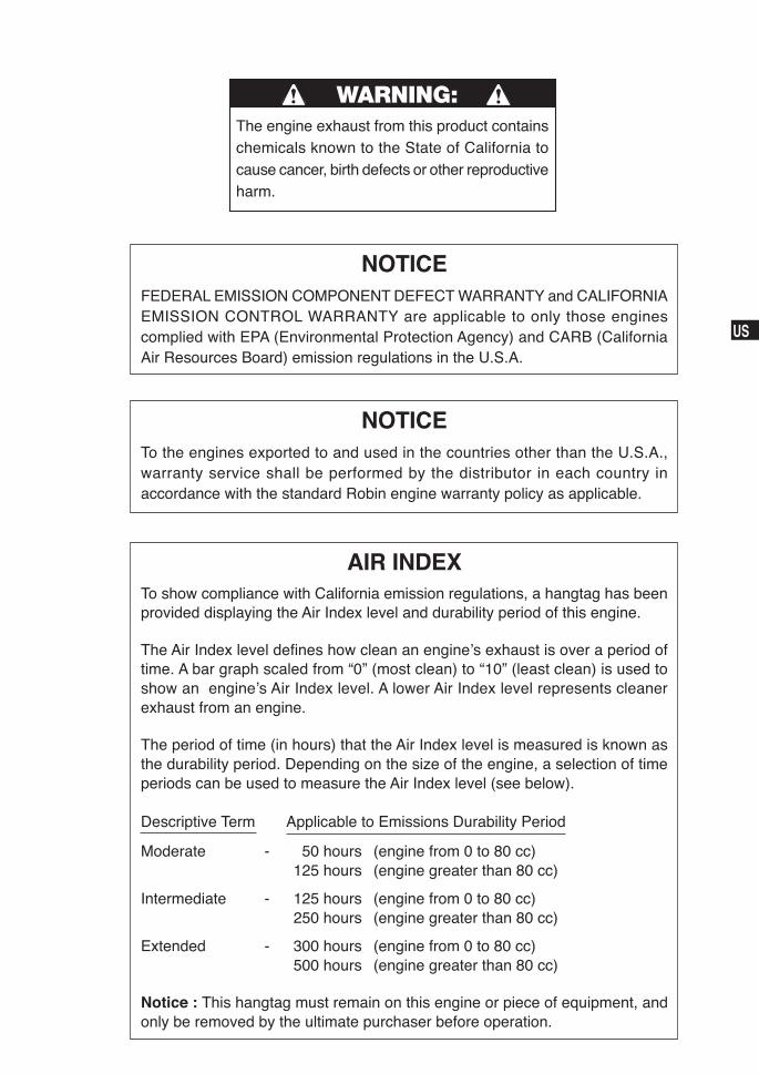
NOTICEFEDERAL EMISSION COMPONENT DEFECT WARRANTY and CALIFORNIAEMISSION CONTROL WARRANTY are applicable to only those enginescomplied with EPA (Environmental Protection Agency) and CARB (CaliforniaAir Resources Board) emission regulations in the U.S.A.
The engine exhaust from this product containschemicals known to the State of California tocause cancer, birth defects or other reproductiveharm.
WARNING:
AIR INDEXTo show compliance with California emission regulations, a hangtag has beenprovided displaying the Air Index level and durability period of this engine.
The Air Index level defines how clean an engine’s exhaust is over a period oftime. A bar graph scaled from “0” (most clean) to “10” (least clean) is used toshow an engine’s Air Index level. A lower Air Index level represents cleanerexhaust from an engine.
The period of time (in hours) that the Air Index level is measured is known asthe durability period. Depending on the size of the engine, a selection of timeperiods can be used to measure the Air Index level (see below).
Descriptive Term Applicable to Emissions Durability Period
Moderate - 50 hours (engine from 0 to 80 cc)125 hours (engine greater than 80 cc)
Intermediate - 125 hours (engine from 0 to 80 cc)250 hours (engine greater than 80 cc)
Extended - 300 hours (engine from 0 to 80 cc)500 hours (engine greater than 80 cc)
Notice : This hangtag must remain on this engine or piece of equipment, andonly be removed by the ultimate purchaser before operation.
NOTICETo the engines exported to and used in the countries other than the U.S.A.,warranty service shall be performed by the distributor in each country inaccordance with the standard Robin engine warranty policy as applicable.
JP
US
GB
DE
FR
NL
ES
IT
PT
GR
NO
SE
FI
DK
RU
CN
AR
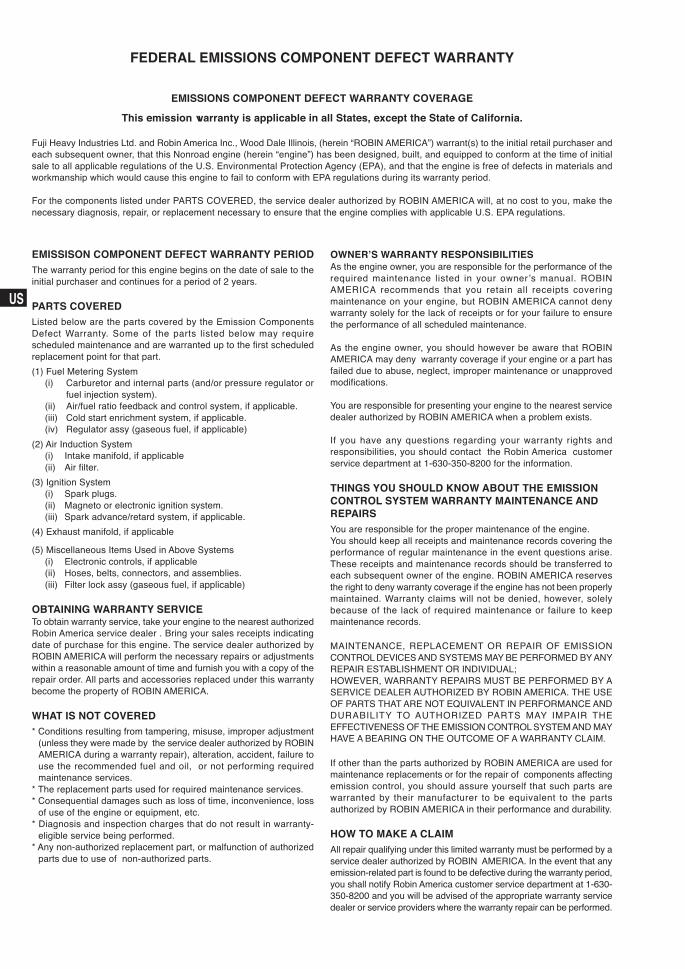
FEDERAL EMISSIONS COMPONENT DEFECT WARRANTY
EMISSIONS COMPONENT DEFECT WARRANTY COVERAGE
This emission warranty is applicable in all States, except the State of California.
Fuji Heavy Industries Ltd. and Robin America Inc., Wood Dale Illinois, (herein “ROBIN AMERICA”) warrant(s) to the initial retail purchaser andeach subsequent owner, that this Nonroad engine (herein “engine”) has been designed, built, and equipped to conform at the time of initialsale to all applicable regulations of the U.S. Environmental Protection Agency (EPA), and that the engine is free of defects in materials andworkmanship which would cause this engine to fail to conform with EPA regulations during its warranty period.
For the components listed under PARTS COVERED, the service dealer authorized by ROBIN AMERICA will, at no cost to you, make thenecessary diagnosis, repair, or replacement necessary to ensure that the engine complies with applicable U.S. EPA regulations.
EMISSISON COMPONENT DEFECT WARRANTY PERIODThe warranty period for this engine begins on the date of sale to theinitial purchaser and continues for a period of 2 years.
PARTS COVEREDListed below are the parts covered by the Emission ComponentsDefect Warranty. Some of the parts listed below may requirescheduled maintenance and are warranted up to the first scheduledreplacement point for that part.
(1) Fuel Metering System(i) Carburetor and internal parts (and/or pressure regulator or
fuel injection system).(ii) Air/fuel ratio feedback and control system, if applicable.(iii) Cold start enrichment system, if applicable.(iv) Regulator assy (gaseous fuel, if applicable)
(2) Air Induction System(i) Intake manifold, if applicable(ii) Air filter.
(3) Ignition System(i) Spark plugs.(ii) Magneto or electronic ignition system.(iii) Spark advance/retard system, if applicable.
(4) Exhaust manifold, if applicable
(5) Miscellaneous Items Used in Above Systems(i) Electronic controls, if applicable(ii) Hoses, belts, connectors, and assemblies.(iii) Filter lock assy (gaseous fuel, if applicable)
OBTAINING WARRANTY SERVICETo obtain warranty service, take your engine to the nearest authorizedRobin America service dealer . Bring your sales receipts indicatingdate of purchase for this engine. The service dealer authorized byROBIN AMERICA will perform the necessary repairs or adjustmentswithin a reasonable amount of time and furnish you with a copy of therepair order. All parts and accessories replaced under this warrantybecome the property of ROBIN AMERICA.
WHAT IS NOT COVERED* Conditions resulting from tampering, misuse, improper adjustment
(unless they were made by the service dealer authorized by ROBINAMERICA during a warranty repair), alteration, accident, failure touse the recommended fuel and oil, or not performing requiredmaintenance services.
* The replacement parts used for required maintenance services.* Consequential damages such as loss of time, inconvenience, loss
of use of the engine or equipment, etc.* Diagnosis and inspection charges that do not result in warranty-
eligible service being performed.* Any non-authorized replacement part, or malfunction of authorized
parts due to use of non-authorized parts.
OWNER’S WARRANTY RESPONSIBILITIESAs the engine owner, you are responsible for the performance of therequired maintenance listed in your owner’s manual. ROBINAMERICA recommends that you retain all receipts coveringmaintenance on your engine, but ROBIN AMERICA cannot denywarranty solely for the lack of receipts or for your failure to ensurethe performance of all scheduled maintenance.
As the engine owner, you should however be aware that ROBINAMERICA may deny warranty coverage if your engine or a part hasfailed due to abuse, neglect, improper maintenance or unapprovedmodifications.
You are responsible for presenting your engine to the nearest servicedealer authorized by ROBIN AMERICA when a problem exists.
If you have any questions regarding your warranty rights andresponsibilities, you should contact the Robin America customerservice department at 1-630-350-8200 for the information.
THINGS YOU SHOULD KNOW ABOUT THE EMISSIONCONTROL SYSTEM WARRANTY MAINTENANCE ANDREPAIRSYou are responsible for the proper maintenance of the engine.You should keep all receipts and maintenance records covering theperformance of regular maintenance in the event questions arise.These receipts and maintenance records should be transferred toeach subsequent owner of the engine. ROBIN AMERICA reservesthe right to deny warranty coverage if the engine has not been properlymaintained. Warranty claims will not be denied, however, solelybecause of the lack of required maintenance or failure to keepmaintenance records.
MAINTENANCE, REPLACEMENT OR REPAIR OF EMISSIONCONTROL DEVICES AND SYSTEMS MAY BE PERFORMED BY ANYREPAIR ESTABLISHMENT OR INDIVIDUAL;HOWEVER, WARRANTY REPAIRS MUST BE PERFORMED BY ASERVICE DEALER AUTHORIZED BY ROBIN AMERICA. THE USEOF PARTS THAT ARE NOT EQUIVALENT IN PERFORMANCE ANDDURABILITY TO AUTHORIZED PARTS MAY IMPAIR THEEFFECTIVENESS OF THE EMISSION CONTROL SYSTEM AND MAYHAVE A BEARING ON THE OUTCOME OF A WARRANTY CLAIM.
If other than the parts authorized by ROBIN AMERICA are used formaintenance replacements or for the repair of components affectingemission control, you should assure yourself that such parts arewarranted by their manufacturer to be equivalent to the partsauthorized by ROBIN AMERICA in their performance and durability.
HOW TO MAKE A CLAIMAll repair qualifying under this limited warranty must be performed by aservice dealer authorized by ROBIN AMERICA. In the event that anyemission-related part is found to be defective during the warranty period,you shall notify Robin America customer service department at 1-630-350-8200 and you will be advised of the appropriate warranty servicedealer or service providers where the warranty repair can be performed.
JP
US
GB
DE
FR
NL
ES
IT
PT
GR
NO
SE
FI
DK
RU
CN
AR
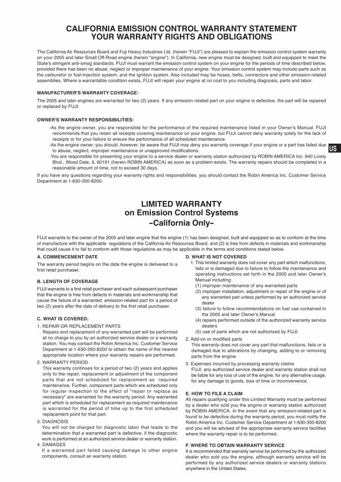
CALIFORNIA EMISSION CONTROL WARRANTY STATEMENTYOUR WARRANTY RIGHTS AND OBLIGATIONS
The California Air Resources Board and Fuji Heavy Industries Ltd. (herein “FUJI”) are pleased to explain the emission control system warrantyon your 2005 and later Small Off-Road engine (herein "engine"). In California, new engine must be designed, built and equipped to meet theState's stringent anti-smog standards. FUJI must warrant the emission control system on your engine for the periods of time described below,provided there has been no abuse, neglect or improper maintenance of your engine. Your emission control system may include parts such asthe carburetor or fuel-injection system, and the ignition system. Also included may be hoses, belts, connectors and other emission-relatedassemblies. Where a warrantable condition exists, FUJI will repair your engine at no cost to you including diagnosis, parts and labor.
MANUFACTURER'S WARRANTY COVERAGE:
The 2005 and later engines are warranted for two (2) years. If any emission related part on your engine is defective, the part will be repairedor replaced by FUJI.
OWNER'S WARRANTY RESPONSIBILITIES:
-As the engine owner, you are responsible for the performance of the required maintenance listed in your Owner's Manual. FUJIrecommends that you retain all receipts covering maintenance on your engine, but FUJI cannot deny warranty solely for the lack ofreceipts or for your failure to ensure the performance of all scheduled maintenance.
-As the engine owner, you should ,however, be aware that FUJI may deny you warranty coverage if your engine or a part has failed dueto abuse, neglect, improper maintenance or unapproved modifications.
-You are responsible for presenting your engine to a service dealer or warranty station authorized by ROBIN AMERICA Inc. 940 LivelyBlvd., Wood Dale, IL 60191 (herein ROBIN AMERICA) as soon as a problem exists. The warranty repairs should be completed in areasonable amount of time, not to exceed 30 days.
If you have any questions regarding your warranty rights and responsibilities, you should contact the Robin America Inc. Customer ServiceDepartment at 1-630-350-8200.
LIMITED WARRANTYon Emission Control Systems
-California Only-
FUJI warrants to the owner of the 2005 and later engine that the engine (1) has been designed, built and equipped so as to conform at the timeof manufacture with the applicable regulations of the California Air Resources Board, and (2) is free from defects in materials and workmanshipthat could cause it to fail to conform with those regulations as may be applicable in the terms and conditions stated below.
A. COMMENCEMENT DATE
The warranty period begins on the date the engine is delivered to afirst retail purchaser.
B. LENGTH OF COVERAGE
FUJI warrants to a first retail purchaser and each subsequent purchaserthat the engine is free from defects in materials and workmanship thatcause the failure of a warranted emission-related part for a period oftwo (2) years after the date of delivery to the first retail purchaser.
C. WHAT IS COVERED:
1. REPAIR OR REPLACEMENT PARTSRepairs and replacement of any warranted part will be performedat no charge to you by an authorized service dealer or a warrantystation. You may contact the Robin America Inc. Customer ServiceDepartment at 1-630-350-8200 to obtain the name of the nearestappropriate location where your warranty repairs are performed.
2. WARRANTY PERIODThis warranty continues for a period of two (2) years and appliesonly to the repair, replacement or adjustment of the componentparts that are not scheduled for replacement as requiredmaintenance. Further, component parts which are scheduled onlyfor regular inspection to the effect of "repair or replace asnecessary" are warranted for the warranty period. Any warrantedpart which is scheduled for replacement as required maintenanceis warranted for the period of time up to the first scheduledreplacement point for that part.
3. DIAGNOSISYou will not be charged for diagnostic labor that leads to thedetermination that a warranted part is defective, if the diagnosticwork is performed at an authorized service dealer or warranty station.
4. DAMAGESIf a warranted part failed causing damage to other enginecomponents, consult an warranty station.
D. WHAT IS NOT COVERED1. This limited warranty does not cover any part which malfunctions,
fails or is damaged due to failure to follow the maintenance andoperating instructions set forth in the 2005 and later Owner'sManual including:(1) improper maintenance of any warranted parts(2) improper installation, adjustment or repair of the engine or of
any warranted part unless performed by an authorized servicedealer
(3) failure to follow recommendations on fuel use contained inthe 2005 and later Owner's Manual
(4) repairs performed outside of the authorized warranty servicedealers
(5) use of parts which are not authorized by FUJI.
2. Add-on or modified partsThis warranty does not cover any part that malfunctions, fails or isdamaged due to alterations by changing, adding to or removingparts from the engine.
3. Expenses incurred by processing warranty claimsFUJI, any authorized service dealer and warranty station shall notbe liable for any loss of use of the engine, for any alternative usage,for any damage to goods, loss of time or inconvenience.
E. HOW TO FILE A CLAIMAll repairs qualifying under this Limited Warranty must be performedby a dealer who sold you the engine or warranty station authorizedby ROBIN AMERICA. In the event that any emission-related part isfound to be defective during the warranty period, you must notify theRobin America Inc. Customer Service Department at 1-630-350-8200and you will be advised of the appropriate warranty service facilitieswhere the warranty repair is to be performed.
F. WHERE TO OBTAIN WARRANTY SERVICEIt is recommended that warranty service be performed by the authorizeddealer who sold you the engine, although warranty service will beperformed by any authorized service dealers or warranty stationsanywhere in the United States.
JP
US
GB
DE
FR
NL
ES
IT
PT
GR
NO
SE
FI
DK
RU
CN
AR
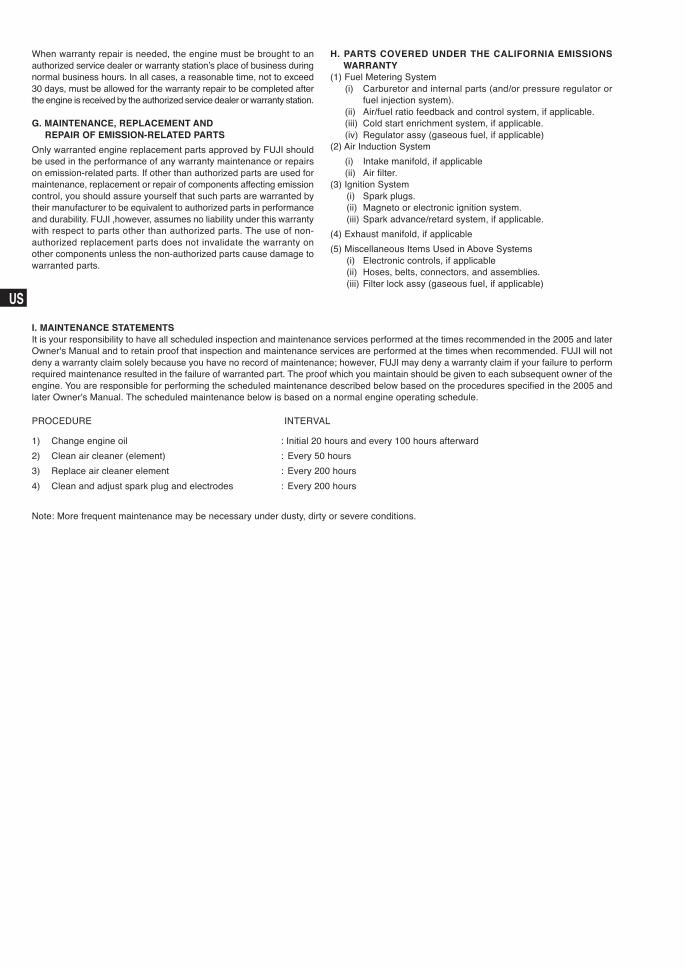
PROCEDURE INTERVAL
1) Change engine oil : Initial 20 hours and every 100 hours afterward
2) Clean air cleaner (element) : Every 50 hours
3) Replace air cleaner element : Every 200 hours
4) Clean and adjust spark plug and electrodes : Every 200 hours
Note: More frequent maintenance may be necessary under dusty, dirty or severe conditions.
When warranty repair is needed, the engine must be brought to anauthorized service dealer or warranty station’s place of business duringnormal business hours. In all cases, a reasonable time, not to exceed30 days, must be allowed for the warranty repair to be completed afterthe engine is received by the authorized service dealer or warranty station.
G. MAINTENANCE, REPLACEMENT ANDREPAIR OF EMISSION-RELATED PARTS
Only warranted engine replacement parts approved by FUJI shouldbe used in the performance of any warranty maintenance or repairson emission-related parts. If other than authorized parts are used formaintenance, replacement or repair of components affecting emissioncontrol, you should assure yourself that such parts are warranted bytheir manufacturer to be equivalent to authorized parts in performanceand durability. FUJI ,however, assumes no liability under this warrantywith respect to parts other than authorized parts. The use of non-authorized replacement parts does not invalidate the warranty onother components unless the non-authorized parts cause damage towarranted parts.
I. MAINTENANCE STATEMENTSIt is your responsibility to have all scheduled inspection and maintenance services performed at the times recommended in the 2005 and laterOwner's Manual and to retain proof that inspection and maintenance services are performed at the times when recommended. FUJI will notdeny a warranty claim solely because you have no record of maintenance; however, FUJI may deny a warranty claim if your failure to performrequired maintenance resulted in the failure of warranted part. The proof which you maintain should be given to each subsequent owner of theengine. You are responsible for performing the scheduled maintenance described below based on the procedures specified in the 2005 andlater Owner's Manual. The scheduled maintenance below is based on a normal engine operating schedule.
H. PARTS COVERED UNDER THE CALIFORNIA EMISSIONSWARRANTY
(1) Fuel Metering System(i) Carburetor and internal parts (and/or pressure regulator or
fuel injection system).(ii) Air/fuel ratio feedback and control system, if applicable.(iii) Cold start enrichment system, if applicable.(iv) Regulator assy (gaseous fuel, if applicable)
(2) Air Induction System
(i) Intake manifold, if applicable(ii) Air filter.
(3) Ignition System(i) Spark plugs.(ii) Magneto or electronic ignition system.(iii) Spark advance/retard system, if applicable.
(4) Exhaust manifold, if applicable
(5) Miscellaneous Items Used in Above Systems(i) Electronic controls, if applicable(ii) Hoses, belts, connectors, and assemblies.(iii) Filter lock assy (gaseous fuel, if applicable)
1
JP
US
GB
DE
FR
NL
ES
IT
PT
GR
NO
SE
FI
DK
RU
CN
ARCONTENTS Page
1. SAFETY PRECAUTIONS… ............................................................................. 2
2. COMPONENTS ................................................................................................ 4
3. PRE-OPERATION CHECKS…......................................................................... 5
4. ELECTRIC STARTER MODELS ...................................................................... 5
5. OPERATING YOUR ENGINE........................................................................... 6
6. MAINTENANCE ............................................................................................... 7
7. PREPARATIONS FOR STORAGE ................................................................... 9
8. OIL SENSOR INSTRUCTIONS (OPTIONAL) .................................................. 9
9. EASY TROUBLESHOOTING ........................................................................... 9
10. SPECIFICATIONS ............................................................................................ 10
PROD NO. SER NO.
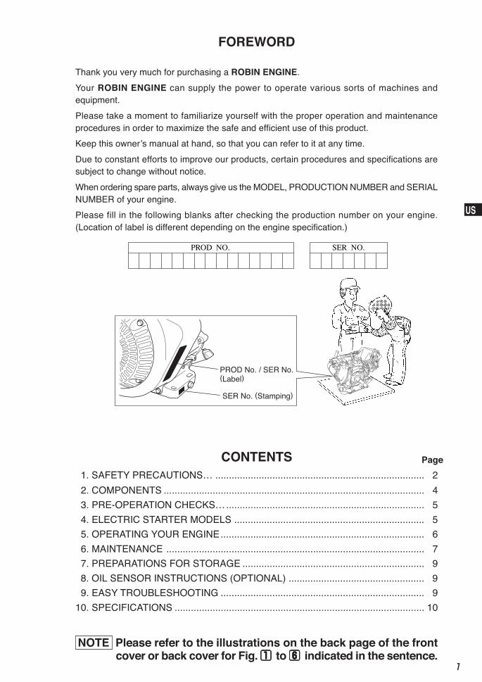
FOREWORD
Thank you very much for purchasing a ROBIN ENGINE.
Your ROBIN ENGINE can supply the power to operate various sorts of machines andequipment.
Please take a moment to familiarize yourself with the proper operation and maintenanceprocedures in order to maximize the safe and efficient use of this product.
Keep this owner’s manual at hand, so that you can refer to it at any time.
Due to constant efforts to improve our products, certain procedures and specifications aresubject to change without notice.
When ordering spare parts, always give us the MODEL, PRODUCTION NUMBER and SERIALNUMBER of your engine.
Please fill in the following blanks after checking the production number on your engine.(Location of label is different depending on the engine specification.)
PROD No. / SER No.(Label)
SER No. (Stamping)
NOTE Please refer to the illustrations on the back page of the frontcover or back cover for Fig. 1 1 1 1 1 to 6 6 6 6 6 indicated in the sentence.
2
JP
US
GB
DE
FR
NL
ES
IT
PT
GR
NO
SE
FI
DK
RU
CN
AR
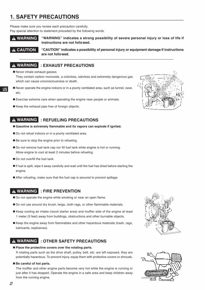
: EXHAUST PRECAUTIONS■ Never inhale exhaust gasses.
They contain carbon monoxide, a colorless, odorless and extremely dangerous gaswhich can cause unconsciousness or death.
■ Never operate the engine indoors or in a poorly ventilated area, such as tunnel, cave,
etc.
■ Exercise extreme care when operating the engine near people or animals.
■ Keep the exhaust pipe free of foreign objects.
: REFUELING PRECAUTIONS■ Gasoline is extremely flammable and its vapors can explode if ignited.
■ Do not refuel indoors or in a poorly ventilated area.
■ Be sure to stop the engine prior to refueling.
■ Do not remove fuel tank cap nor fill fuel tank while engine is hot or running.
Allow engine to cool at least 2 minutes before refueling.
■ Do not overfill the fuel tank.
■ If fuel is spilt, wipe it away carefully and wait until the fuel has dried before starting the
engine.
■ After refueling, make sure that the fuel cap is secured to prevent spillage.
: FIRE PREVENTION■ Do not operate the engine while smoking or near an open flame.
■ Do not use around dry brush, twigs, cloth rags, or other flammable materials.
■ Keep cooling air intake (recoil starter area) and muffler side of the engine at least
1 meter (3 feet) away from buildings, obstructions and other burnable objects.
■ Keep the engine away from flammables and other hazardous materials (trash, rags,
lubricants, explosives).
: OTHER SAFETY PRECAUTIONS■ Place the protective covers over the rotating parts.
If rotating parts such as the drive shaft, pulley, belt, etc. are left exposed, they arepotentially hazardous. To prevent injury, equip them with protective covers or shrouds.
■ Be careful of hot parts.
The muffler and other engine parts become very hot while the engine is running orjust after it has stopped. Operate the engine in a safe area and keep children awayfrom the running engine.
1. SAFETY PRECAUTIONS
WARNING
Please make sure you review each precaution carefully.Pay special attention to statement preceded by the following words.
WARNING
WARNING
WARNING
WARNING
CAUTION
“WARNING” indicates a strong possibility of severe personal injury or loss of life ifinstructions are not followed.
“CAUTION” indicates a possibility of personal injury or equipment damage if instructionsare not followed.
3
JP
US
GB
DE
FR
NL
ES
IT
PT
GR
NO
SE
FI
DK
RU
CN
AR
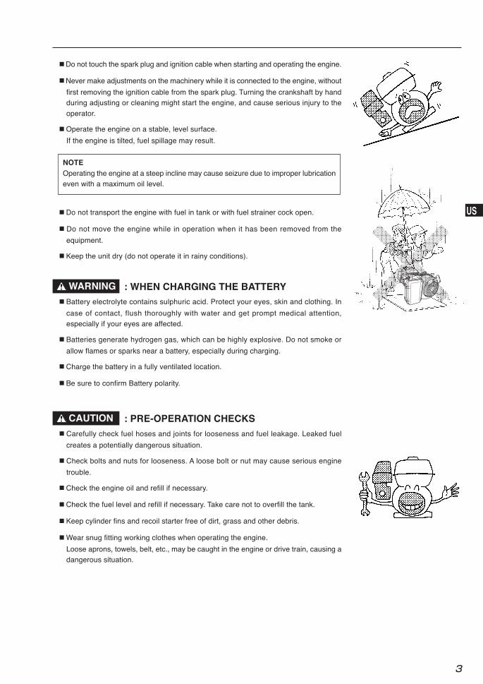
■ Do not touch the spark plug and ignition cable when starting and operating the engine.
■ Never make adjustments on the machinery while it is connected to the engine, without
first removing the ignition cable from the spark plug. Turning the crankshaft by handduring adjusting or cleaning might start the engine, and cause serious injury to the
operator.
■ Operate the engine on a stable, level surface.
If the engine is tilted, fuel spillage may result.
■ Do not transport the engine with fuel in tank or with fuel strainer cock open.
■ Do not move the engine while in operation when it has been removed from the
equipment.
■ Keep the unit dry (do not operate it in rainy conditions).
NOTEOperating the engine at a steep incline may cause seizure due to improper lubricationeven with a maximum oil level.
CAUTION : PRE-OPERATION CHECKS■ Carefully check fuel hoses and joints for looseness and fuel leakage. Leaked fuel
creates a potentially dangerous situation.
■ Check bolts and nuts for looseness. A loose bolt or nut may cause serious engine
trouble.
■ Check the engine oil and refill if necessary.
■ Check the fuel level and refill if necessary. Take care not to overfill the tank.
■ Keep cylinder fins and recoil starter free of dirt, grass and other debris.
■ Wear snug fitting working clothes when operating the engine.
Loose aprons, towels, belt, etc., may be caught in the engine or drive train, causing adangerous situation.
: WHEN CHARGING THE BATTERY■ Battery electrolyte contains sulphuric acid. Protect your eyes, skin and clothing. In
case of contact, flush thoroughly with water and get prompt medical attention,especially if your eyes are affected.
■ Batteries generate hydrogen gas, which can be highly explosive. Do not smoke or
allow flames or sparks near a battery, especially during charging.
■ Charge the battery in a fully ventilated location.
■ Be sure to confirm Battery polarity.
WARNING
4
JP
US
GB
DE
FR
NL
ES
IT
PT
GR
NO
SE
FI
DK
RU
CN
AR
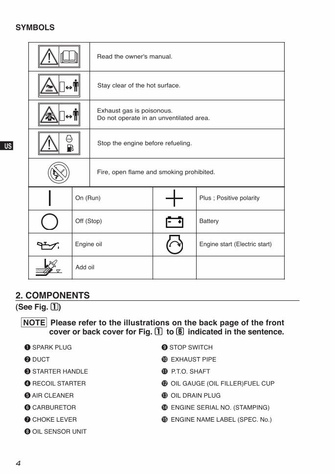
.launams'renwoehtdaeR
.ecafrustohehtforaelcyatS
.suonosiopsisagtsuahxE.aeradetalitnevnunanietarepotonoD
.gnileufererofebenigneehtpotS
.detibihorpgnikomsdnaemalfnepo,eriF
)nuR(nO ytiralopevitisoP;sulP
)potS(ffO yrettaB
lioenignE )tratscirtcelE(tratsenignE
lioddA
SYMBOLS
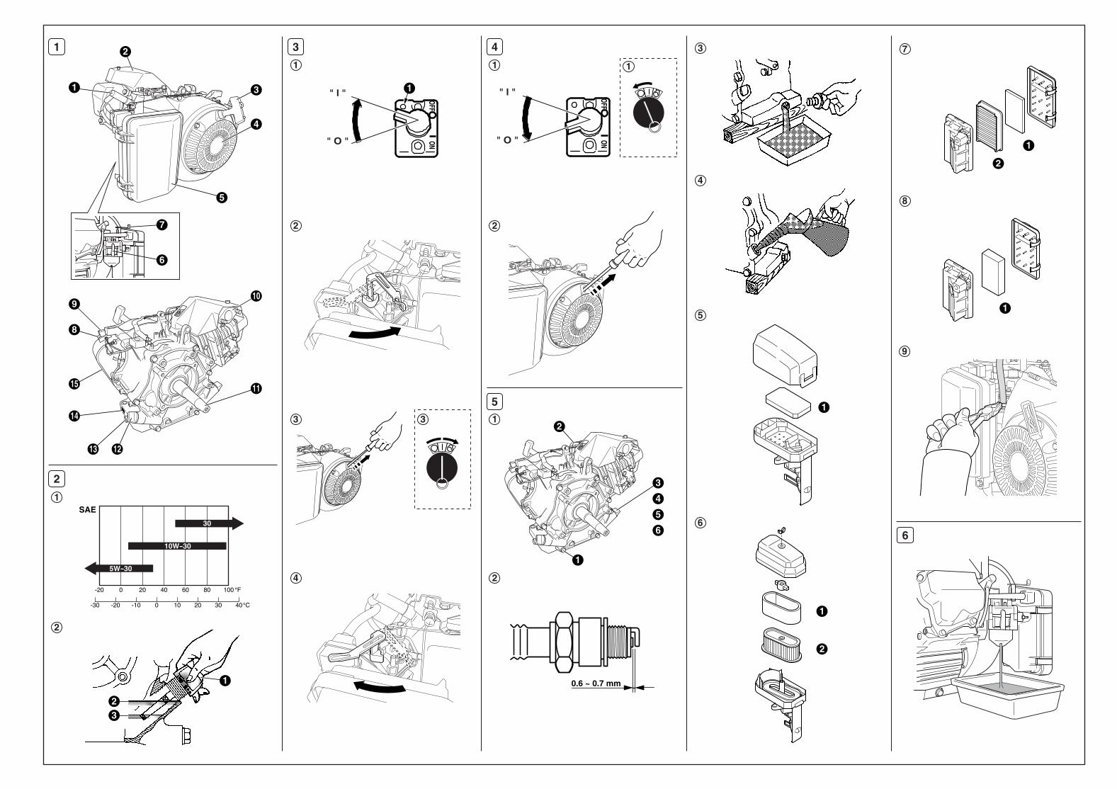
q SPARK PLUG
w DUCT
e STARTER HANDLE
r RECOIL STARTER
t AIR CLEANER
y CARBURETOR
u CHOKE LEVER
i OIL SENSOR UNIT
2. COMPONENTS(See Fig. 11111)
o STOP SWITCH
!0 EXHAUST PIPE
!1 P.T.O. SHAFT
!2 OIL GAUGE (OIL FILLER)FUEL CUP
!3 OIL DRAIN PLUG
!4 ENGINE SERIAL NO. (STAMPING)
!5 ENGINE NAME LABEL (SPEC. No.)
NOTE Please refer to the illustrations on the back page of the frontcover or back cover for Fig. 1 1 1 1 1 to 6 6 6 6 6 indicated in the sentence.
5
JP
US
GB
DE
FR
NL
ES
IT
PT
GR
NO
SE
FI
DK
RU
CN
AR
For electric starter operation, proper electric wiring
arrangements are needed before normal engine operation.
1. BATTERY■ Use a battery rated 12V-24AH or larger.
4. ELECTRIC STARTER MODELS
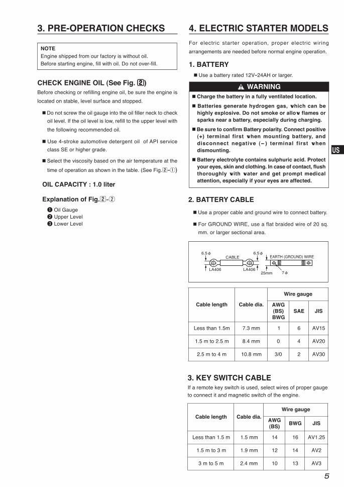
2. BATTERY CABLE
3. KEY SWITCH CABLE
htgnelelbaC .aidelbaC
eguageriW
GWA)SB(GWB
EAS SIJ
m5.1nahtsseL mm3.7 1 6 51VA
m5.2otm5.1 mm4.8 0 4 02VA
m4otm5.2 mm8.01 0/3 2 03VA
■ Use a proper cable and ground wire to connect battery.
■ For GROUND WIRE, use a flat braided wire of 20 sq.
mm. or larger sectional area.
htgnelelbaC .aidelbaCeguageriW
GWA)SB(
GWB SIJ
m5.1nahtsseL mm5.1 41 61 52.1VA
m3otm5.1 mm9.1 21 41 2VA
m5otm3 mm4.2 01 31 3VA
3. PRE-OPERATION CHECKS
NOTEEngine shipped from our factory is without oil.Before starting engine, fill with oil. Do not over-fill.
CHECK ENGINE OIL (See Fig. 22222)Before checking or refilling engine oil, be sure the engine is
located on stable, level surface and stopped.
■ Do not screw the oil gauge into the oil filler neck to check
oil level. If the oil level is low, refill to the upper level with
the following recommended oil.
■ Use 4-stroke automotive detergent oil of API service
class SE or higher grade.
■ Select the viscosity based on the air temperature at the
time of operation as shown in the table. (See Fig.2-q)
OIL CAPACITY : 1.0 liter
Explanation of Fig.2-w
q Oil Gaugew Upper Levele Lower Level
If a remote key switch is used, select wires of proper gaugeto connect it and magnetic switch of the engine.
LA406 LA406
CABLE EARTH (GROUND) WIRE
25mm
6.5
7
6.5
■ Charge the battery in a fully ventilated location.
■ Batteries generate hydrogen gas, which can behighly explosive. Do not smoke or allow flames orsparks near a battery, especially during charging.
■ Be sure to confirm Battery polarity. Connect positive(+) terminal first when mounting battery, anddisconnect negative (- ) terminal first whendismounting.
■ Battery electrolyte contains sulphuric acid. Protectyour eyes, skin and clothing. In case of contact, flushthoroughly with water and get prompt medicalattention, especially if your eyes are affected.
WARNING
6
JP
US
GB
DE
FR
NL
ES
IT
PT
GR
NO
SE
FI
DK
RU
CN
AR
1. STARTING
(1) Open the fuel cock.
(2) Turn the STOP SWITCH to the position “ I ” (ON).(See Fig.3-q)
(3) Close the choke lever. (See Fig.3-w)
■ If the engine is cold or the ambient temperature is low,
close the choke lever fully.
■ If the engine is warm or the ambient temperature is high,open the choke lever half-way, or keep it fully open.
(4) Pull the starter handle slowly until resistance is felt. Thisis the “compression” point. Return the handle to its
original position and pull swiftly. Do not pull out the ropeall the way. After starting the engine, allow the starterhandle to return to its original position while still holdingthe handle. (See Fig.3-e)
5. OPERATING YOUR ENGINE(See Fig. 33333)
2. RUNNINGAfter the engine starts, warm it up without load for a fewminutes.
3. STOPPING(1) Allow the engine to run for 1 or 2 minutes before stopping.
(2) Turn the STOP SWITCH (or KEY SWITCH) counterclock-
wise to the position “○ ” (OFF). (See Fig.4-q)
(3) Close the fuel cock.
(4) Pull the starter handle slowly and return the handle to its
original position when resistance is felt. This operation
is necessary to prevent outside moist air from intruding
into the combustion chamber. (See Fig.4-w)
(5) After starting the engine, gradually open choke by turningthe choke lever and finally keep it fully opened. Do notfully open the choke lever immediately when the engineis cold or the ambient temperature is low, because theengine may stop. (See Fig.3-r)
FOR ELECTRIC STARTER MODELS.Insert the key into the key slot and set it at the “ I ” (ON)position. Turn it to the right (START position) to start theengine. (See Fig.3-e)
■ Do not operate the electric starter continuously formore than 5 secounds, even if the engine dose notstart.
■ If the engine failed to start, set the key to the “ I ”(ON) position and wait for about 10 secounds beforeretrying.
■ Never turn the key switch to the START position whileengine is running.
5. WIRING DIAGRAM(RECOIL STARTER MODELS)
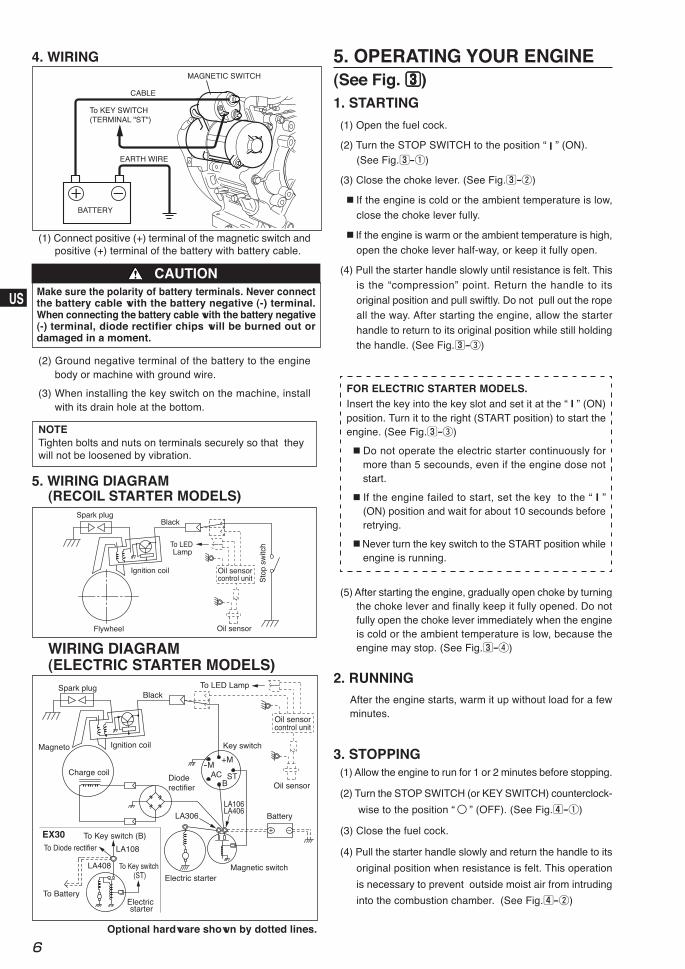
(2) Ground negative terminal of the battery to the enginebody or machine with ground wire.
(3) When installing the key switch on the machine, installwith its drain hole at the bottom.
WIRING DIAGRAM(ELECTRIC STARTER MODELS)
Optional hardware shown by dotted lines.
NOTETighten bolts and nuts on terminals securely so that theywill not be loosened by vibration.
4. WIRING
To Key switch (ST)
To Key switch (B)
To Diode rectifier
EX30
To Battery
LA108
LA408
Spark plugBlack
+M-M
STB
AC
LA106LA406
LA306
Charge coil
Magneto
Electric starterMagnetic switch
Key switch
To LED Lamp
Oil sensor
Oil sensorcontrol unit
Battery
Dioderectifier
Ignition coil
Electric starter
Spark plugBlack
Sto
p sw
itch
Ignition coil
Flywheel
To LED Lamp
Oil sensor
Oil sensorcontrol unit
BATTERY
To KEY SWITCH(TERMINAL "ST")
CABLE
EARTH WIRE
MAGNETIC SWITCH
(1) Connect positive (+) terminal of the magnetic switch andpositive (+) terminal of the battery with battery cable.
Make sure the polarity of battery terminals. Never connectthe battery cable with the battery negative (-) terminal.When connecting the battery cable with the battery negative(-) terminal, diode rectifier chips will be burned out ordamaged in a moment.
CAUTION
7
JP
US
GB
DE
FR
NL
ES
IT
PT
GR
NO
SE
FI
DK
RU
CN
AR
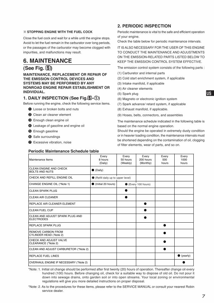
Maintenance ItemsEvery
8 hours(Daily)
Every50 hours(Weekly)
Every200 hours(Monthly)
Every500
hours
Every1000hours
CLEAN ENGINE AND CHECKBOLTS AND NUTS ● (Daily)
CHECK AND REFILL ENGINE OIL
CHANGE ENGINE OIL (*Note 1) ● (Initial 20 hours) ●
CLEAN SPARK PLUG ●
CLEAN AIR CLEANER ●
REPLACE AIR CLEANER ELEMENT ●
CLEAN FUEL CUP ●
CLEAN AND ADJUST SPARK PLUG ANDELECTRODES ●
REPLACE SPARK PLUG ●
REMOVE CARBON FROMCYLINDER HEAD (*Note 2)
●
CHECK AND ADJUST VALVECLEARANCE (*Note 2) ●
CLEAN AND ADJUST CARBURETOR (*Note 2) ●
REPLACE FUEL LINES ● (yearly)
OVERHAUL ENGINE IF NECESSARY (*Note 2) ●
6. MAINTENANCE(See Fig. 55555)
※STOPPING ENGINE WITH THE FUEL COCK
Close the fuel cock and wait for a while until the engine stops.Avoid to let the fuel remain in the carburator over long periods,
or the passages of the carburator may become clogged withimpurities, and malfunctions may result.
MAINTENANCE, REPLACEMENT OR REPAIR OFTHE EMISSION CONTROL DEVICES ANDSYSTEMS MAY BE PERFORMED BY ANYNONROAD ENGINE REPAIR ESTABLISHMENT ORINDIVIDUAL.
1. DAILY INSPECTION (See Fig.55555-qqqqq)Before running the engine, check the following service items.
q Loose or broken bolts and nuts
w Clean air cleaner element
e Enough clean engine oil
r Leakage of gasoline and engine oil
t Enough gasoline
y Safe surroundings
u Excessive vibration, noise
The emission control system consists of the following parts :
(1) Carburetor and internal parts
(2) Cold start enrichment system, if applicable
(3) Intake manifold, if applicable
(4) Air cleaner elements
(5) Spark plug
(6) Magneto or electronic ignition system
(7) Spark advance/ retard system, if applicable
(8) Exhaust manifold, if applicable.
(9) Hoses, belts, connectors, and assembles
The maintenance schedule indicated in the following table isbased on the normal engine operation.
Should the engine be operated in extremely dusty conditionor in heavier loading condition, the maintenance intervals mustbe shortened depending on the contamination of oil, cloggingof filter elements, wear of parts, and so on.
2. PERIODIC INSPECTIONPeriodic maintenance is vital to the safe and efficient operationof your engine.
Check the table below for periodic maintenance intervals.
IT IS ALSO NECESSARY FOR THE USER OF THIS ENGINETO CONDUCT THE MAINTENANCE AND ADJUSTMENTSON THE EMISSION-RELATED PARTS LISTED BELOW TOKEEP THE EMISSION CONTROL SYSTEM EFFECTIVE.
*Note: 1. Initial oil change should be performed after first twenty (20) hours of operation. Thereafter change oil everyhundred (100) hours. Before changing oil, check for a suitable way to dispose of old oil. Do not pour itdown into sewage drains, onto garden soil or into open streams. Your local zoning or environmentalregulations will give you more detailed instructions on proper disposal.
*Note: 2. As to the procedures for these items, please refer to the SERVICE MANUAL or consult your nearest Robinservice dealer.
Periodic Maintenance Schedule table
● (Every 100 hours)
● (Refill daily up to upper level)
8
JP
US
GB
DE
FR
NL
ES
IT
PT
GR
NO
SE
FI
DK
RU
CN
AR
(3) Refer to page 5 for the recommended oil.
■ Always use the best grade and clean oil. Contaminated
oil, poor quality oil and shortage of oil cause damage toengine or shorten the engine life.
8. CHECK BATTERY
6. FUEL HOSE REPLACEMENT (See Fig.55555-ooooo)
Replace the fuel hose every 1,000 hours or every year.
If fuel leaks from fuel hose, replace the fuel hose immediately.
Take extreme caution when replacing fuelhose ; gasoline is extremely flammable.
WARNING
WARNING Flame Prohibited
If the electrolyte fluid is below level line, refill with distilledwater to the upper level line.
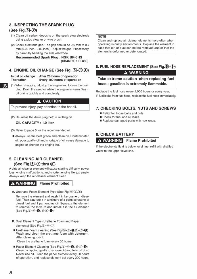
3. INSPECTING THE SPARK PLUG(See Fig.55555-wwwww)
(1) Clean off carbon deposits on the spark plug electrodeusing a plug cleaner or wire brush.
(2) Check electrode gap. The gap should be 0.6 mm to 0.7mm (0.02 inch.-0.03 inch.). Adjust the gap, if necessary,by carefully bending the side electrode.Recommended Spark Plug : NGK BR-6HS
(CHAMPION RL86C)
4. ENGINE OIL CHANGE (See Fig. 55555-eeeee,rrrrr)Initial oil change : After 20 hours of operationThereafter : Every 100 hours of operation
(1) When changing oil, stop the engine and loosen the drainplug. Drain the used oil while the engine is warm. Warmoil drains quickly and completely.
(2) Re-install the drain plug before refilling oil.
OIL CAPACITY : 1.0 liter
To prevent injury, pay attention to the hot oil.
CAUTION
5. CLEANING AIR CLEANER(See Fig.55555-ttttt thru iiiii)
A dirty air cleaner element will cause starting difficulty, powerloss, engine malfunctions, and shorten engine life extremely.Always keep the air cleaner element clean.
WARNING Flame Prohibited
NOTEClean and replace air cleaner elements more often whenoperating in dusty environments. Replace the element incase that dirt or dust can not be removed and/or that theelement is deformed or deteriorated.
7. CHECKING BOLTS, NUTS AND SCREWS■ Retighten loose bolts and nuts.■ Check for fuel and oil leaks.■ Replace damaged parts with new ones.
A. Urethane Foam Element Type (See Fig.5-t,i)
Remove the element and wash it in kerosene or dieselfuel. Then saturate it in a mixture of 3 parts kerosene ordiesel fuel and 1 part engine oil. Squeeze the elementto remove the mixture and install it in the air cleaner.(See Fig.5-t-q,5-i-q)
B. Dual Element Type (Urethane Foam and Paperelements) (See Fig.5-y,u)
■ Urethane Foam cleaning (See Fig.5-y-q,5-u-q)Wash and clean the urethane foam with detergent.After cleaning, dry it. Clean the urethane foam every 50 hours.
■ Paper Element Cleaning (See Fig.5-y-w,5-u-w)Clean by tapping gently to remove dirt and blow off dust.Never use oil. Clean the paper element every 50 hoursof operation, and replace element set every 200 hours.
9
JP
US
GB
DE
FR
NL
ES
IT
PT
GR
NO
SE
FI
DK
RU
CN
AR
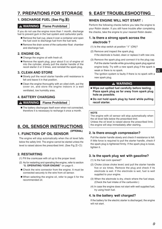
1. DISCHARGE FUEL (See Fig.66666)
7. PREPATIONS FOR STORAGE
If you do not use the engine more than 1 month, dischargefuel to prevent gum in the fuel system and carburetor parts.
■ Remove the fuel cup, place it over a container and openthe fuel cock to discharge fuel from the fuel tank.
■ Remove the drain screw of the carburetor float chamberand discharge fuel.
2. ENGINE OIL■ Change the engine oil with fresh oil.
■ Remove the spark plug, pour about 5 cc of engine oilinto the cylinder, slowly pull the starter handle of therecoil starter 2 or 3 times, and reinstall the spark plug.
3. CLEAN AND STORE■ Slowly pull the recoil starter handle until resistance is
felt and leave it in that position.
■ Clean the engine thoroughly with an oiled cloth, put thecover on, and store the engine indoors in a well
ventilated, low humidity area.
WARNING Flame Prohibited
1. FUNCTION OF OIL SENSORThe engine will stop automatically when the oil level fallsbelow the safety limit. The engine cannot be started unless the
level is raised above the prescribed limit. (See Fig.2-w)
8. OIL SENSOR INSTRUCTIONS(OPTIONAL)
2. RESTARTING(1) Fill the crankcase with oil up to the proper level.
(2) As for restarting and operating the engine, refer to section“5. OPERATING YOUR ENGINE” on page 6 .
■ Check the wire connector from the engine. It must beconnected securely to the wire from oil sensor.
■ When selecting the engine oil, refer to page 5 for therecommended oil.
■ The battery discharges itself even when not connected,therefore it is necessary to recharge it once a month.
WARNING Flame Prohibited
4. BATTERY CHARGING
WHEN ENGINE WILL NOT START :Perform the following checks before you take the engine toyour Robin dealer. If you still have trouble after completingthe checks, take the engine to your nearest Robin dealer.
1. Is there a strong spark across theelectrode ?
(1) Is the stop switch at position “ I ” (ON)?
(2) Remove and inspect the spark plug.If the electrode is fouled, clean or replace it with new one.
(3) Remove the spark plug and connect it to the plug cap.
Pull the starter handle while grounding spark plug againstengine body. Try with a new spark plug if the spark isweak or there is no spark.The ignition system is faulty if there is no spark with a
new spark plug.
9. EASY TROUBLESHOOTING
■ Wipe out spilled fuel carefully before testing.Place spark plug as far away from spark plughole as possible.
■ Do not hold spark plug by hand while pullingrecoil starter.
WARNING
NOTEThe engine with oil sensor will stop automatically whenthe oil level falls below the prescribed limit.Unless the oil level is raised above the prescribed limit,the engine will stop immediately after starting.
3. Is the spark plug wet with gasoline?(1) Is the fuel cock opened?
(2) Choke (close choke lever) and pull the starter handlefive or six times. Remove the plug and check if itselectrode is wet. If the electrode is wet, fuel is wellsupplied to your engine.
(3) When the electrode is dry, check where the fuel stops.(Check the fuel intake of the carburetor.)
(4) In case the engine does not start with well supplied fuel,try using fresh fuel.
4. Is the battery well charged?
Pull the starter handle slowly and check if resistance is felt.If little force is required to pull the starter handle, check ifthe spark plug is tightened firmly. If the spark plug is loose,tighten it.
2. Is there enough compression?
If the battery for the electric starter is discharged, the enginewill not start.
10
JP
US
GB
DE
FR
NL
ES
IT
PT
GR
NO
SE
FI
DK
RU
CN
AR
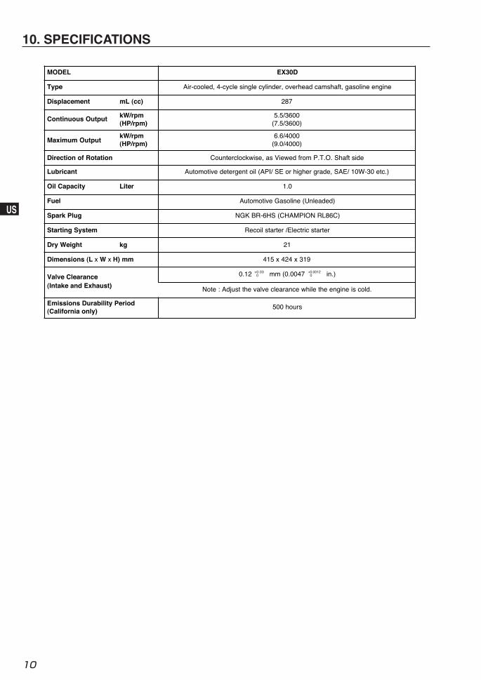
10. SPECIFICATIONS
MODEL EX30D
Type Air-cooled, 4-cycle single cylinder, overhead camshaft, gasoline engine
Displacement mL (cc) 287
Continuous Output kW/rpm(HP/rpm)
5.5/3600(7.5/3600)
Maximum OutputkW/rpm(HP/rpm)
6.6/4000(9.0/4000)
Direction of Rotation Counterclockwise, as Viewed from P.T.O. Shaft side
Lubricant Automotive detergent oil (API/ SE or higher grade, SAE/ 10W-30 etc.)
Oil Capacity Liter 1.0
Fuel Automotive Gasoline (Unleaded)
Spark Plug NGK BR-6HS (CHAMPION RL86C)
Starting System Recoil starter /Electric starter
Dry Weight kg 21
Dimensions (L x W x H) mm 415 x 424 x 319
Valve Clearance(Intake and Exhaust)
0.12 mm (0.0047 in.)
Note : Adjust the valve clearance while the engine is cold.
Emissions Durability Period(California only)
500 hours
+0.03 0
+0.0012 0