college of engineering & computational sciences senior...
TRANSCRIPT

College of Engineering &
Computational Sciences
Senior Design Trade Fair
April 23, 2015


Capstone Design Program C O L O R A D O S C H O O L O F M I N E S
College of Engineering and Computational Sciences G O L D E N , C O L O R A D O 8 0 4 0 1 - 1 8 8 7
___________________________________________________________________________________
Cap s ton e D es i gn P ro g ram Col l eg e o f En gin eer in g & Co mp u ta t i on a l Sc i en c es
1 5 0 0 I l l i n o i s S t . • Go ld en , CO 8 0 4 0 1
Des ig n@ mines . e du
A Special Word of Thanks to Our Judges
It is my pleasure to offer a personal welcome to the judges of the Spring 2015 Colorado School of
Mines College of Engineering and Computational Sciences Trade Fair. We appreciate your
willingness to take time from your normal activities to evaluate our senior’s capstone design
projects. The opportunity for our students to get feedback from experienced engineers is
invaluable.
Senior design allows our students to demonstrate the engineering knowledge that they have spent
four years acquiring. We encourage you to spend time with the design teams and to inquire about
their projects and their designs. But also ask about their design process, because in the final
analysis, senior design is as much about learning the process of design as it is about creating a
design. As these students enter the workforce, it is their ability to use the design thinking methods
that they have learned that will serve them most in their careers.
We are proud of our students and their accomplishments and hope you are equally impressed. If
you would like to get more involved in our program, we are always in search of more project
sponsors. Let us know!
Again, thank you and Happy Judging!
Kevin L. Moore
Dean, College of Engineering
& Computational Sciences


Colorado School of Mines thanks the individuals and families listed below who have
provided valuable support to the Senior Design students present today.
Program Partners
J. Don Thorson
Program Supporters Program Donors
Al Cohen Family Jamie Eichenberger
Matt & Kim Sands
Robert Amaro
Colorado School of Mines thanks the companies and organizations listed below who have
provided valuable support to the Senior Design students present today.
Program Partners
Baker Hughes Shell Oil Company
Program Sponsors
Chevron
Program Supporters
Kiewit Phillips 66
Woodward Inc.
Program Donors
AISC Archer Western Baseline Engineering,
Planning and Surveying
Bowman Consulting CVJ Axles* Exxon Mobil
EMJ* Hearly Keeter Trucking Holcim Inc.
ICAST Engineering IEEE KL&A
Pitsco Education Schlumberger Technology
Corporation
Super Vac*
Steel Dynamics Zimkor*
*Denotes donation of materials, services, or supplies to the program.

Sponsoring the Program
The Capstone Design Program provides Mines students with multidisciplinary, professional
practice experiences as part of their education through projects that matter. The program relies on
the generosity of our program sponsors. If you, or your organization, are interested in supporting
the program please consider making a financial gift at giving.mines.edu. Your gift is tax deductible
and will make a huge impact on our students.
PROGRAM PARTNERS Donate $25,000 or greater
Your Funds support the needs of
many teams. In addition, partners
receive:
An invitation to, and recognition at the
beginning-of-semester Project Kickoff event.
All Sponsor, Supporter, and Donor benefits.
PROGRAM SPONSORS Donate $10,000 - $24,999
Your funds support the needs of
multiple teams. In addition, sponsors
receive:
An invitation to, and recognition at the end-of-
semester Trade Fair event.
All Supporter and Donor benefits.
PROGRAM SUPPORTERS Donate $5,000 - $9,999
Your funds support the needs of a
single team. In addition, supporters
receive:
Recognition on the program’s website, and on
signage in the Capstone Design Lab in the Brown
Building Basement
All Donor benefits.
PROGRAM DONORS Donate up to $4,999
Donors receive:
Recognition in the end-of-semester Trade Fair
Program and a formal letter of thanks from the
Mines Foundation.

Colorado School of Mines thanks the individuals and organizations listed below who have
served as clients for the student teams presenting today. Your donation of time, talent, and
material support to our students is greatly appreciated.
Boulder Journey School Sam Hall
Brown and Caldwell Jamie Eichenberger
Chevron Phillips Chemical Erik Lord and Will Rommel
City of Golden Anne Beierle
CSM Center for Space Resources Angel Abbud Madrid
CSM Metallurgical and Materials
Engineering Department
Geoff Brennecka, Ivan Cornejo, and Terry
Lowe
Denver Zoological Foundation Paul Quick
Edward Kraemer Sons, Inc. Mike McNish
GoFarm Eileen Regan
Holcim (US) Inc. Brooke Smartz
Kiewit Ben Seling, Dave Tedrow, Rob Hoefer,
and Victor Mazza
Medtronic Tom Cilke
Oldcastle Precast Dan Dodson
POWER Engineers, Inc. James Trumble
Reactive Adaptations Jake O’Connor
Shell Matt Sands
University of Colorado at Denver Michael Melonis
United States Olympic Committee Mounir Zok
United States Antarctic Program Patricia Douglas
Unaffiliated Paul Brayford
CSM Civil and Environmental Engineering
Department
Jeff Holley
CSM Electrical Engineering and Computer
Science Department
Randy Haupt
CSM Mechanical Engineering Department Cameron Turner, Derrick Rodriguez, Greg
Bogin, Joel Bach, John Steele, Nils Tilton,
Ozkan Celik, and Ray Zhang

Becoming a Client
The Capstone Design program in the College of Engineering and Computation Sciences (CECS)
pushes students to go beyond their textbook training and solve real-world design problems. Every
semester the college has over 50 student design teams who need great challenges to engage with.
What opportunities does your organization have that could be addressed by a student team?
SUGGESTED
DONATION
Corporate project sponsors are asked to provide a donation of $8,000 to
the CSM Foundation. Up to $2,000 of that donation is made available
to the student team for purchasing materials. The additional amount is
used to support the program facilities, staff, and overhead. Government
agencies, NGO's and startups may request exemption from the
suggested donation.
TIME
COMMITMENT
The involvement of the project sponsor is a key factor in the success of
the project. Great project sponsors will commit one individual for
approximately 1 hour per week to support the student team. In addition,
any training or on-site resources that you can make available to the
students are greatly appreciated.
OTHER Student access to construction sites, manufacturing partners, or other
company resources is always appreciated by the students.
PROFILE OF A GREAT PARTNER
The most successful industry partners share the following traits:
View sponsoring a project as an outreach activity which helps prepare their junior
engineers for management.
Choose projects from their “nice-to-have” list and avoid having students on their critical
path.
Treat students like an entry-level engineer and plan on providing guidance throughout the
process.
GETTING STARTED
Send an email to [email protected] to start exploring opportunities with program staff.

General Information Regarding Trade Fair
JUDGE’S AGENDA
Time Description Location
7:00 - 7:30 Registration and Breakfast Served Student Center Main Ballrooms
7:30 – 8:45 Breakfast Program
492 Essay Winners Announced
491 Elevator Pitch Presentations
Student Center Main Ballrooms
8:45 – 9:00 Transition to Trade Fair Lockridge Arena
9:00 – 11:00 Trade Fair Lockridge Arena
FINDING YOUR WAY AROUND
A floor plan and map of the Trade Fair is available on the back of this program for your convenience.
JUDGES LOUNGE
Snacks and beverages are available for judges in the Judges Lounge. Please feel free to take a break from
talking with the teams and grab a beverage or snack in the lounge at any time.
GRADING
We seek to achieve consistency in grading between the teams. With that in mind, the senior design faculty
have developed the scoring rubric. Each row includes prompting descriptions that are intended to guide the
evaluation process. Each description has an associated point value with it.
To completely grade a team, please select a single number from each row of the grading matrix. Sum the
numbers (one from each row) and enter the total team score at the bottom of the ballot. Please return the
form to the registration table when it is complete.

Spring 2015 Design Projects
Each year senior students in the civil, electrical, environmental, and mechanical engineering
programs in the College of Engineering and Computational Sciences take a two-semester course
sequence in engineering design targeted at enhancing their problem-solving skills. Corporations,
government agencies and other professional organizations, as well as individual clients, provide
projects for the student teams of five to eight students to work on. Students spend the academic
year developing solutions for the projects to which they have been assigned, using tools they have
learned throughout their careers at Mines.
This semester, we are proud to present the work of our 40 design teams. Their collaborative design
work culminates in today’s Senior Design Trade Fair. A list of the teams is provided below. In
addition, each team has provided a one page synopsis of their design challenge which is included
in the following pages.
TABLE OF PROJECTS
Team
Number
Team Name Project
F14-01 Master Mines 2015 ASCE Concrete Canoe Competition
F14-02 That Awkward Moment 2015 ASCE/AISC National Student Steel Bridge
Competition
F14-03 Mines Trussworthy Steel 2015 ASCE/AISC National Student Steel Bridge
Competition
F14-04 Shell EcoMarathon 2015 Shell Ecomarathon Competition
F14-05 Baja Blasters 2015 SAE Baja Competition
F14-06 Golden Performance Systems SAE Formula Dry-Sump
F14-07 Formula Win SAE Formula Dashboard System
F14-08/09 CSM Blasterbotica 2015 NASA Robotic Mining Competition
F14-10 WindMiners 2015 National Wind Competition
F14-11 MINESat Mines CubeSat Initiative
F14-12 The Power Group Integrated Protection and Control System
F14-13 Warrior Wear Energy Absorbing Device for Sportswear to Reduce
Trauma
F14-14 Wastewater Wizards Brown and Caldwell Challenge
F14-15 Mountainside Consulting Lookout Mountain Lid - Roadway Profiles and Structural
Design
F14-16 Creative Drainage Solutions Lookout Mountain Lid - Water Quality and Drainage
F14-17 Applied Thermal Solutions Heating System for Metal Nan structuring Machine
F14-18 Bright Futures STEM Light Lab for Boulder Journey School
F14-19 Superior Surveying Mines Survey Field Update
F14-20 The A-Team Mines Survey Field Update
F14-21 One n' Done Anchor Universal, Precast Anchor Design
F14-22 SODAR SODAR Phase II

F14-23 Re-Balance Weight Distribution Training Device and Exercise Games
for Stroke Patients
F14-24 Weederbot Team WeederBot Robotic Control System
F14-25 Turnip the Beet Food Hub Building System
F14-26 Engineering Collective CP Chemical Outfall Pond pH Creep Remediation
F14-27 Golden Energy Solutions GoFarm Food Hub Energy System
F14-28 Dynamic Energy Providers GoFarm Food Hub Power System
F14-29 Team Dyno Small Electric Motor Dynamometer
F14-30 Three-Oh Designs Functional Tracking/Hinge System and Portable Stand
F14-31 Enlightened Robotics Mobil Indoor Routing
F14-32 Colorado CrankWorks Reverse Gearing for Hand-cranked Mountain Bike
F14-33 Team Platinum Multi-mode Furnace Sensor
F14-34 Omeganaut Vibrations Learning Lab
F14-35 The Jackson VI Fluids & Controls Learning Lab
F14-36 Smart Drops Fluids & Controls Learning Lab
F14-37 Continuous Glass Melter Continuous Glass Research Melter
F14-38 MicroWinder Team Off-axis Micro Coil Winder
F14-39 Jump Around Time of Flight Tracking System
F14-40 Peak Performance Athlete Instrumentation System

ASCE Concrete Canoe 01
Client: David Tedrow
Faculty Advisor: Branden Gonzales
Consultants Ben Seling
Brooke Smartz
Team Name: Master Mines
Team Members: Heather Mergentime, Rachel Steenerson, Laura Brewer, Brett Mahon, Broc
Patterson, Dina Vakarchuk, Rachel Nagel
This project involves designing, building, and testing a concrete canoe for the American Society
of Civil Engineers Rocky Mountain Regional Concrete Canoe Competition in accordance with the
rules and regulations. The canoe is judged on aesthetic appeal, performance in numerous races, a
design paper, and an oral presentation. The team was responsible for designing the canoe hull
geometry, concrete mix, reinforcement, and formwork as well as incorporating a unique theme.
The team started the design process by reverse engineering the hull design from the CSM 2014
canoe. The team utilized a flat bottom design (shown in the F2 below) as opposed to last years’
shallow arch. This design improved the stability and maneuverability of the canoe. To minimize
the chances of cracking, the team computed the maximum cracking moment and bending moments
for four loading scenarios: display, transportation, the two paddler race, and the four paddler race.
Since cracking will result in water seeping through the concrete, the team compared the maximum
positive and negative bending moments to the maximum cracking moment of the canoe. This
confirmed the stresses developed in the canoe would not exceed the rupture strength of the
concrete.
This years’ concrete canoe is named Si Mangavang, after the large plank boat built by the Taoist
oarsmen of Orchard Island in 2011. This unique canoe was crafted to honor the tribesmen’s rich
marine culture, and featured elaborate paintings in red, black, and white (shown in F1 below).
Master Mines constructed the Si Mangavang to represent
Taoist values of craftsmanship, teamwork, community, and
adventurous spirit. Each team member played a vital role in
the project, and worked toward continuing the Colorado
School of Mines’ ASCE tradition of passionate
competition.
F1: Cutaway Section Showing
Construction Process
F2: Bottom view of hull design

ASCE/AISC Steel Bridge Competition 02
Client(s): Kiewit: Mr. Victor Mazzarella
Faculty Advisor: Dr. Cooper Consultants Mr. Ben Seling, Dave Genova
Team Name: That Awkward Moment Team Members: Melody Clay, Peter Eisinger, Ryan Hooper, Nathaniel Ober,
Audrianna Ricotta, Spencer Wells
The ASCE/AISC Student Steel Bridge Competition challenges teams to design and fabricate a
bridge that complies with all loading conditions and site conditions. That Awkward Moment used
RISA, structural modeling software, to account for design strengths and determine the best initial
bridge design. Following the design review in the fall the team optimized the design and
incorporated suggested changes. That awkward moment chose to use dovetail connections in order
to expedite construction during competition. The bridge had to span a 6’6” gap so one major
feature of our design was to make minimal connections over the river.
Once the final design was created the team created cut-sheets in Solidworks, which were
comprehensively reviewed by our technical consultant Dave Genova at Zimkor. Fabrication took
approximately three months and involved grinding, welding, and cutting steel members. The team
created a workout program in order to build team dynamics and prepare members for the athletic
challenge of building the bridge within the least time possible. That Awkward moment optimized
construction time of the bridge to 13 minutes and 15 seconds by SpringFest, the internal bridge
competition at Mines
Figure 1 RISA Model Figure 2: Fabricated Structure

AISC Steel Bridge Competition 03
Client(s): Rob Hoefer
Faculty Advisor: Paul Kaster
Consultants Ben Seling
Team Name: Mines Trussworthy Steel
Team Members: Alexi Scherkenbach, Mark Sundstrom, Max Ransom, Niki Hall, Travis
White, Eli Ludtke
Our project is to design, build, and test a small scale steel bridge that will compete in the AISC - ASCE
Student Steel Bridge Competition. The competition mimics bridge building and construction in remote
areas. For this reason, the bridge will be made up of multiple members that can be easily transported to the
site. The competition tracks the assembly time to represent building the full scale in one dry season.
Construction over the river without the ability to touch the river presents another complex challenge. Our
design utilizes a curved overhead truss feature to take the load off of the decking members and reduce
overall weight. The decking members are tilted inwards while the truss is tilted outwards to increase lateral
stiffness. Once assembled, the bridge will span a gap of 18’6” and fit within a 5’ tall by 5’ wide bridge
envelope. The bridge can support 2600 pounds of load in the middle while only deflecting 0.6 inches. The
bridge itself only weighs 257 pounds and can be constructed in 29 minutes. The competition rules use the
bridge weight, deflection, and assembly time to compute a composite score. We spent the first six months
of the project designing and modeling the bridge in both RISA 3D and SolidWorks. The next two months
were spent fabricating the bridge. The project consists of three competitions. The first is a local CSM
competition, regionals, and finally nationals.

Shell Eco-Marathon Competition 04
Client(s): Matt Sands
Faculty Advisor: Bill Sekulic
Consultants Darek Bruzgo
Team Name: Miner Fuel Consumption
Team Members: Leo Frenkel, Kyle Hilberg, Jenny Lee, Evan Manning,
Sara Starks, Jon Tran, Warren Randall, Justin Wahler
This year Team Miner Fuel
Consumption was chosen to
represent the Colorado School
of Mines in the 2015 Shell Eco-
marathon Americas
Competition. In this
competition teams must design
and build a hyper fuel-efficient,
one-person vehicle. Overall fuel
economy will determine the
winner in each vehicle category
or class. The specific area of the
competition for the team is the diesel fuel category where they have set a goal of reaching over
1000 mpg.
Team Miner Fuel Consumption initially received the car from last year’s competition and was
asked to troubleshoot and redesign the vehicle to achieve a stable prototype that would complete
the race. Some of the problems that the team encountered were to increase stability of the vehicle
and reduce weight from the previous year as well as increase overall efficiency. With the help of
Dr. Robert Amaro, John Jezek and everyone at the Mines machine shop, proper analysis and design
were conducted and the team finalized the vehicle. Some notable features of the car include
electronic throttle control, optimized engine mounting systems, and adjustable wheel alignment
for optimal handling. The final design now weighs 210 lbs. (a reduction of ~50 lbs.) with a very
aerodynamic carbon fiber body, low rolling resistance, proper safety specifications, and tuned
engine and gearing components. The team competed in the event from April 9th-12th in Detroit,
Michigan and would love to share the results with you and answer any questions when you stop
by our booth during Trade Fair.

2015 SAE Mini Baja 05
Client(s): Derrick Rodriguez
Faculty Advisor: Jered Dean
Consultants Frank & Kay Peterson
Team Name: Baja Blasters 2015
Team Members: Aaron Fisk, Zachary Fitzgerald, Matt Heidebrecht, Jacob Hill, Justin
Mattice, Matt McDonnell, Kyle Weinmeister
The 2015 CSM Mini Baja team will
represent CSM in the Baja SAE
competition in Portland, OR. This
competition simulates a real-world
engineering project in which teams must
design, manufacture, test, market, and
race a single-operator, off-road vehicle.
Our vehicle must conform to technical
specifications put forth by SAE, without
compromising driver safety or vehicle
performance. In Oregon, the vehicle will
be tested in rock crawl, hill climb, and
maneuverability events, as well as a
four-hour endurance race. Teams are scored on design, cost, and performance.
Our team inherited the 2014 CSM Baja vehicle, but ultimately decided to completely redesign and
rebuild a new vehicle. Primary focus was given to lowering the vehicle’s weight, minimizing
construction costs and complexity, and improving the robustness and performance of the previous
teams’ designs. All components—with the exception of the stock engine mandated by
competition—were re-engineered, using previous teams’ experience for guidance, and the most
important components were analyzed using FEA or physical testing. We also maintained a top-
level assembly containing all vehicle systems in Solidworks in order to verify tool and component
clearances.
The final design is significantly smaller and lighter than previous teams’ vehicles. It features a
continuously variable transmission that transfers power to the locked differential, maximizing
power output at the wheels from the small 10 HP engine. The vehicle also incorporates a drop-out
engine and tunable suspension components that potential owners could use to customize or easily
access vehicle systems for maintenance. Our vehicle will be a strong competitor in all competition
categories, and has the potential for a top ten finish.

FSAE Dry Sump Lubrication System 06
Client(s): Dr. Gregory Bogin and FSAE
Faculty Advisor: Dr. Ron Slovikoski
Consultants Engines and Car Racing
Team Name: Golden Performance Systems
Team Members: Sam Compton, Sam Fletcher, Jace Kelly, Preston Kosiara, Geoff Odgers,
Ignacio Villen
Our team goal was to increase the performance of the Formula Society of Automotive Engineers
race vehicle by designing a dry sump lubrication system. Dry sump systems differ from traditional
wet sump engine lubrication systems in that the primary engine oil reservoir exists in a remote
location, rather than at the bottom of the engine block in a deep pan.
The advantage to the dry sump is that the shallower oil pan allows the engine to be placed lower
in the vehicle, lowering the overall center of gravity of the vehicle. Vehicles with a lower center
of gravity can corner harder and remain more stable during tight maneuvering than vehicles with
a higher center of gravity.
Employing a dry sump lubrication system includes several key design challenges. Moving oil to
and from the remote oil reservoir requires well matched flowrates between the engine circulating
oil pumps within the engine and the scavenge oil pump circulating oil to the reservoir. Moreover,
designing a system that can be integrated with an engine originally configured as a wet sump
presents an immense logistical challenge. Finally, the dry sump system must be completely
reliable; any failure to properly lubricate engine components during operation will result in
catastrophic engine failure.
Our final system is the result of approximately 1000 hours of labor. We were responsible for the
design, fabrication, and retrofitting of our dry sump lubrication system. Along with the dry sump
components, we have prepared extensive documentation of our research and design process.
Figure 3: Dry Sump System and Engine
Figure 2: Oil Pan Machine Tool Path

Formula SAE Dashboard 07
Client(s): CSM FSAE Team
Faculty Advisor: Dr. Chuck Reynerson
Consultants Dr. Greg Bogin
Team Name: Formula Win
Team Members: Kendall Samuel, Colin Royston, Grant Spencer
Keith Nygard, Corbin Smith
The Society of Automotive Engineers (SAE) is an international professional society that concerns
itself with the development of technical standards for all industries related to transportation. SAE
is also known for its collegiate design challenges intended to develop engineering students’
competency in their profession by giving them experience designing, manufacturing, and
competing with each other. This Senior Design team is working alongside the Colorado School of
Mines Formula SAE Team to build an open-wheeled formula-style car. This team is responsible
for designing and manufacturing a digital dashboard system to provide the driver with vital
information on the car’s operating conditions and to aid those team members tasked with
calibrating the engine control system. Due to space constraints, the display will be steering-wheel-
mounted. The proposed characteristics
to display during vehicle operation
include engine temperature (coolant and
oil), engine speed, vehicle speed, oil
pressure warnings, and various other
failure indication lights. By analyzing
vehicle data, power can safely be
increased while also improving
reliability and detecting bugs in many of
the interconnected systems required to
keep and engine and car running
properly. The addition of speed
monitoring will help decrease lap times
and push the vehicle to its limits safely
and consistently. RPM monitoring will help avoid engine and transmission damage and keep the
driver out of harm’s way and protect the time and money invested by the Colorado School of
Mines FSAE Team and the various sponsors that provided support along the way.
Figure 4 Professional Formula Wheel

NASA Robotic Mining Competition 08/09
Client(s): Dr. Angel Abbud-Madrid
Faculty Advisor: Dr. Christopher Dreyer
Consultants Dr. Ozkan Celik
Team Name: Blasterbotica
Team Members: Lucas Brockman, Nichole Cusack, Ryan Gerney, Laine Greaves-Smith,
William Holleman, Kathryn Kostecka, Michael Kuzminsky, David Long,
Ryan Mack, Kaitlyn Martin, Zachary Nahman, Taylor Ray, Eduardo
Urquidi, Scott Von Thun
Team Blasterbotica was tasked with designing, testing, and building a rover to participate in the
Sixth Annual NASA Robotic Mining Competition. In this competition, university students operate
rovers designed to collect, transport, and deliver a minimum of 10 kilograms of simulated regolith
within a 10 minute time period while traversing an arena containing several obstacles.
The design project was divided into six subsystems. The Drivetrain subsystem is comprised of a
chained-tank treaded system with spring suspension which allows the rover to cross the arena. The
Excavation subsystem utilizes a bucket ladder to excavate regolith and transport it to the Regolith
Delivery subsystem. The excavator moves along a curvilinear rail system so that the rover
complies with the required envelope dimensions at the start of the match, and is able to move to
other positions that allow for excavation and regolith delivery. The Regolith Delivery subsystem
is a dump truck system operated by linear actuators allowing for storage of regolith while the rover
is crossing the arena as well as the exportation of regolith into the designated collection bin. The
Sensing subsystem consists of a variety of sensors to determine the position of the rover in the
arena. The Controls subsystem takes data from the Sensing subsystem and uses a Graphical User
Interface with a controller to allow for tele-operative control of the rover. Prototyping and testing
of these subsystems was completed to ensure that each subsystem interfaces properly to produce
a functional and competitive rover.

DOE Collegiate Wind Competition 10
Client(s): Dr. Cameron Turner
Faculty Advisor: Dr. Yitz Finch
Consultants Dr. Kathryn Johnson
Team Name: WindMiners
Team Members: Michael Brocious, Amanda Chaney, Connor Fritcher, Bryce Gorove,
Tyrenny Hidy, Victoria Kosinska,
Jason Ron, Colin Tombari
The 2014-2015 DOE Collegiate Wind Competition Team is tasked with designing a small scale
wind turbine system for the DOE Collegiate Wind Competition against nine other universities on
April 29th – May 2nd, 2015. The completed turbine must fit inside a 45cm x 45cm x 45cm cube,
and must be able to withstand continuous wind speeds of a maximum 14 m/s. The turbine must be
capable of braking when required, and cannot have any battery system.
There are five tests the team can be scored on, including the power curve performance, cut-in wind
speed, control at maximum power, durability, and safety tests. These tests each vary between ten
and twenty percent of the team’s total wind tunnel score. Testing is 60% of the overall score, and
a comprehensive technical design report, due April 13th, is 40% of the team’s overall score. Each
category is weighed and considered accordingly in the design of this system.
Rotor blades have been designed using a Schmitz optimization
method designed to a tip speed ratio of 4, dictating the most
effective distribution of chord length and pitch angle for the
blades. The blades are to be built using selective laser sintering,
which produces a true-to-form part made of light weight, rigid
polymer. A 3-bladed rotor was chosen over 5+ blade design due
to diminishing returns in power extraction due to Bentz limit.
A parametric flow simulation has been conducted to determine
the no-rotation, or startup torque produced by the rotor for any given wind speed. A BEM Theory
solver was used to predict rotor performance.
Startup torque is a primary concern when selecting a generator. A new motor with lower starting
torque is likely to be chosen to replace the current stepper motor to more closely match the rotor
torque at low wind speed, in order to achieve a lower cut-in speed and negate the necessity of a
gearing system. The motor is wired to also serve as an effective electronic brake.
The nacelle is designed to effectively interface the rotor with the electrical components. The
nacelle is designed to include all electrical components while minimizing free space, weight, and
minimal bearing spacing to avoid shaft whirl and cantilever bending. The final nacelle will include
a thrust bearing and a fin to allow passive reorientation facing the direction of the wind.

Mines CubeSat Initiative 11
Client(s): Dr. Randy Haupt
Faculty Advisor: Dr. Payam Nayeri
Consultants:
Dr. Atef Elsherbeni, Prof. Jered Dean
Team Name: MINESat (Multiple Imaging Nano-Efficient Satellite)
Team Members: Timothy Blondin, Garrett Hoch, Ana Ilic, Michael Kissinger, Joe Lichthardt,
Ross Peters
With the recent growth in aerospace and communication industries, there is a great need for
engineers who can design robust satellite systems. The design of CubeSats, small-scale satellites
used for data acquisition in low-earth orbit, provides essential experience for students interested
in these industries. In August 2014, Colorado School of Mines organized the institution’s first
CubeSat design team with the intention of submitting a formal design proposal to the NASA
CubeSat Launch Initiative by Fall 2017. MINESat (Multiple Imaging Nano-Efficient Satellite) is
a nano-satellite used to collect Earth imaging data in multiple electromagnetic spectrums. In the
first year, design has been focused on the satellite. In the next two years, design will shift to the
ground station, and then to launch and deployment logistics. Throughout the duration of this
project, the MINESat team is also actively fundraising in order to fabricate a space-rated final
design.
In order to demonstrate a proof of concept for the imaging, communication, and control systems,
an Alpha Prototype has been developed over the past few months. The prototype has been designed
with commercial parts to remotely capture an image, transmit the data to a ground station model,
and display the image once reassembled. At the Senior Design Trade Fair on April 23, the
MINESat team will demonstrate its Alpha Prototype to the general public, and will present its
results from the first year of satellite development.

Protection & SCADA Integration 12
Client(s): James Trumble at POWER Engineers
Faculty Advisor: Paul Kaster
Consultants Dr. Ravel Ammerman
Team Name: The Power Group
Team Members: Lucas Cook, Kyle Feaster, Sarah Holmes, Derek Russell, Clinton Smith,
Bryan Wickstrom, Andrew Wilson
The purpose of this project was to design and implement the protection and communication
systems for a small substation provided by POWER Engineers. The protection system is
responsible for detecting and responding to faults and other anomalies in the substation. This
involves using protective relays to monitor quantities such as the current in a line, and send
commands to open circuit breakers and isolate the problem. The communication, or Supervisory
Control And Data Acquisition (SCADA) system is responsible for sending measurements and
breaker status data to a control center, as well as providing control of the substation components.
These two systems combine to allow operators to open and close breakers, analyze the cause of a
fault, and monitor the substation from a remote location.
The protection scheme was
developed according to the
following five criteria: reliability,
selectivity, economics, speed, and
simplicity. The protection settings
were verified using fault studies
performed both by hand and with
the help of computer simulations.
The settings were also verified to
be compliant with the applicable
IEEE standards. The SCADA
system was developed using a data
concentrator to take the data points
from the relays and send them to a
Human Machine Interface (HMI)
that allows the user to monitor the
system and send commands. All of
the relays and the data concentrator
are made by Schweitzer
Engineering Laboratories (SEL).
Physical testing and design demonstration was made possible by SEL, who generously donated all
of the relays and the data concentrator to the school for this team and future teams to use.
SEL Relays in a substation

Energy Absorbing Device for
Sportswear
13
Client(s): Dr. Terry Lowe and Kady Zinke
Faculty Advisor: Mirna Mattjik
Consultants Dr. Lauren Cooper
Team Name: Warrior Wear
Team Members: Leah Brown, Katie Duvall, Jaime Leon, William McCarthy, William
Schvetz, Madeline Woodard
The energy absorbing device in question is a hybrid pad that includes a shear-thickening fluid and
a micro-truss structure and will be used for impact protection. The pad will be secured at the knee
of dance pants as shown below in Figure 1. Warrior Wear’s focus for this project was the micro-
truss structure, which is the primary source of energy absorption and impact force reduction in the
pad. Warrior Wear worked alongside a Materials and Metallurgical (MME) senior design team in
order to fabricate the micro-truss design alternatives created. An initial proof of concept, shown
below in Figure 2, was presented to the team before beginning the project and was used as a
foundation for other design alternatives of the micro-truss structure. Warrior Wear was asked to
develop a validated design tool in order to explore and optimize alternative designs of the micro-
truss structure to maximize impact protection and manufacturability. This tool is an array of
designs in SolidWorks that can be manipulated for finite element analysis (FEA) for any future
analyses that must be performed. In order to develop this tool, the team tested alternatives with
FEA then 3D printed a physical prototype for the MME team to test and compare with the FEA
results.
Figure 5: Kadyluxe Dancewear (Provided by Dr. Lowe)
Figure 6: Micro-Truss Initial Proof of Concept Stress
Distribution

Brown and Caldwell 14
Client(s): Brown and Caldwell – Jamie Eichenberger
Faculty Advisor: Lee Landkamer
Consultants Linda Figueroa
Team Name: Wastewater Wizards
Team Members: Evon Harmon, Katie Sexton, Lindsey Freytag, MacKenzie King, Rebecca
Erickson, Will Porter
The Wastewater Wizards were challenged by the engineering firm Brown and Caldwell to design
a chemical feed system for the Littleton/Englewood Wastewater Treatment Plant (L/E WWTP).
The purpose of the chemical feed system is to remove phosphorus to enable the L/E WWTP to
meet new nutrient criteria set forth by the Colorado Department of Public Health and Environment.
The new nutrient criteria require that phosphorus discharge is limited to less than 1 mg/L by the
year 2020. The team’s deliverables included selecting the chemical and proper dosage, locating
where in the process the chemical should be added, and designing the chemical feed system to a
30% design level.
The team determined that ferric chloride will be used to remove phosphorus though co-
precipitation with ferric oxy-hydroxides. Ferric chloride was chosen over sodium aluminate and
ferrous chloride after performing jar testing with wastewater from several locations at the plant.
The optimum dosage of ferric chloride was also determined by these jar tests. After the analysis
of multiple factors at each location, including lifecycle cost and process impacts, the team decided
that the chemical will be added immediately following the solids contact tanks, with the resulting
precipitated solids removed by the secondary clarifiers. The chemical feed building design
includes appropriately sized tanks, pumps, and pipes using materials compatible with the selected
chemicals. The feed system was designed to be compatible with the existing structures and
buildings, and allows for flexibility to change the precipitation chemical if needed in the future.

Lookout Mountain Lid Structure 15
Client(s): Anne Beierle
Faculty Advisor: Lee Landkamer Consultants Joe Crocker, Mike McNish
Team Name: Mountainside Consulting
Team Members: Michelle Danaher, Jeri Mero, Krystina Pacheco, David Ploense, Meaghan
Schwindt, Adam Vogel, Brad Wood
Mountainside Consulting worked with the City of Golden in Colorado to design a bridge structure
that allows 19th Street to pass over US 6. This design provides safe access for pedestrians and
cyclists, as well as connects the community west of US 6 to downtown Golden. The structure will
support both a park and roadway separated by trees and grass covered berms.
The specific live and dead loads that will be applied to the deck of the bridge were calculated for
both the park and roadway, with the roadway presenting the largest load at 640 lb/ft2. In order to
minimize the load presented by the park, lightweight manufactured soil that was originally
developed for rooftop gardens will be used for the park. An adjacent box-girder design supported
mid-span by columns was selected for reasons of constructability and accessibility as the support
structure for the bridge. The deck slab, adjacent box girders, pier cap, mid-span support columns
and bridge abutments were designed to the proper size and strength based on the maximum
roadway load. Both sides of the bridge will use this design because the bridge will be built in two
phases; the park side will carry traffic during construction of the roadway side of the bridge. A
cost estimate for the lid structure was also completed. Additional calculations have been completed
to determine the amount of excavation that will be needed to lower US 6 under 19th Street.
Photo Courtesy of City of Golden
Cross section of bridge at mid-span;
showing bridge deck, box girders, pier
cap and support columns

Highway 6 and 19th Street Stormwater
Drainage and Treatment System
16
Client(s): Anne Beierle, City of Golden
Faculty Advisor: Lee Landkamer
Consultants Terri Hogue, Mike McNish
Team Name: Creative Drainage Solutions
Team Members: Claire Levinson, Dave Jones, Erik Sheader-Smith, Maria Blakely, Nicole
Neals, Susan Paret
The City of Golden is redesigning the intersection of Highway 6 and 19th Street. The Highway 6
profile will be lowered approximately 25 feet under a new bridge structure for 19th Street. The
new bridge structure over Highway 6 will be designed to accommodate both vehicular traffic and
a large park area for public use. The lowering of US 6
will necessitate a drainage system to convey
stormwater from the newly created low point.
The scope of the project encompassed calculating
runoff into the intersection, designing subsurface
piping and surface channels to carry water away from
the area, and designing a passive water treatment
feature to improve the water quality of the runoff. The
team considered public and client input along with
regulatory requirements to design a system that would
meet the needs of Golden and satisfy the requests of
the surrounding community and its residents. Carlson
Civil AutoCAD, drainage basin topography and soil
types, and National Oceanic and Atmospheric
Administration precipitation estimates were used to
determine the peak runoff flow rate from the drainage
basin during a 100-year flood event. Using this peak
runoff value, the Urban Storm Drainage Criteria
Manuals, and engineering principles, the pipe size and
slope required to convey the water to Clear Creek was
determined. In addition, an extended detention
treatment system was designed to improve the water
quality of the storm water runoff and placed in a
suitable location.
Proposed Highway 6 and 19th Street
Intersection Redesign
Drainage Basin Map
Source: City of Golden

Control System for ECAP-C 17
Client(s): Dr. Terry Lowe
Faculty Advisor: Dr. Yitz Finch
Consultants Dr. John Berger
Team Name: Applied Thermal Solutions
Team Members: Malek Awad, Taylor Bettine, Matthew DeGeorge, James Derrickson,
Logan Nissenson, Benson Tan
Applied Thermal Solutions has
been tasked with the project to
improve the ECAP-C machine
with a heating and cooling control
system. Currently, the ECAP-C
machine resides in Hill Hall where
it performs an interesting
experiment on metal samples. A
metal sample passes through the
machine and, through friction and
pressure, is bent at a severe
deformation angle. This bending
allows the metal to align its grain
structure, causing the metal to
become stronger as a result. The
piece of metal, called a billet, is preheated before it enters the machine. It loses its heat quickly
while moving through the machine because the machine itself is a huge heat sink. While
undergoing the shearing process, the billet generates a large amount of heat. Often, this heat is
larger than the desired temperature for the shearing process. It is important that the heat at the
shearing section be controlled so that the desired metal characteristics develop during the shearing
process.
It is the duty of Thermal Heating Solutions to develop a control system that maintains the billet’s
heat during its path through the machine, keeps the billet at the correct temperature during the
shearing process, and cools the billet down as quickly as possible after the process has ended. If
done successfully this new process can change the way that metal is produced in the World. The
metal coming out of the ECAP-C machine has strength greater than alloys. The finishing of this
project can lead to stronger metals worldwide.

“The Illumidor”- An Interactive Light Lab 18
Client(s): Boulder Journey School – Sam Hall
Faculty Advisor: Mirna Mattjik
Consultants Jenifer Blacklock
Team Name: Bright Futures
Team Members: Brent Last, Joshua Madole, Tyson Manning, Joshua Martinez, Lauren Revis,
Jasmine Sanchez
Boulder Journey School is a private institution located in Boulder, Colorado driven by inspiring
children ages six months to six years to explore the world around them. Their facility features
many technology-related activities that encourage children to create their own learning experience.
The school has requested for Bright Futures to design an open-ended module centered around
investigating light and its properties. The design is focused on safety, mobility, student learning
and ease of use. Bright Futures has applied their engineering expertise to analyze the safety and
functionality of the design. Analysis conducted includes failure modes, user feedback and safety
testing. Bright Futures will deliver “The Illumidor,” an interactive box with various light fixtures
built for children ages six months to six years; inspiring all ages. In addition to the light box itself,
Bright Futures will also deliver a complete drawing package and user manual. The Illumidor
features one large LED light panel, moveable LED light pods, fixed lights and color-changing light
strips. On/Off buttons and a color-changing wheel add to the interactive element of the light box.

Mines Survey Field Update 19
Client(s): Jeff Holley
Faculty Advisor: Branden Gonzales
Consultants Dre Guerra
Team Name: Superior Surveying
Team Members: Brad Burback, Stephanie Ecker, Kyle Hampton, Taylor Madden, Kate
Percival, Samantha Stokes
The Colorado School of Mines Survey Field, located south of Mines Park, is an important part of
Mines and it’s engineering history. The site is currently used for Civil Engineering field sessions
and surveying courses, but the field was once part of every major’s field session, and holds both
sentimental and historical value for numerous Mines alumni.
Superior Surveying has completed a detailed proposal for updates to the Mines Survey Field for
the client, Jeff Holley. The team performed surveys of the existing site and conducted site and soil
analyses in order to develop a grading plan, site plan (Figure 1), drainage plan, and proposed site
designs that comply with local, state, and federal regulations.
Proposed improvements to the Mines Survey Field include a new parking lot featuring a permeable
pavement system that will enhance the aesthetic appeal of the area, and increases drainage
throughout the site. Additionally, updates to the existing building provide a new patio area for
congregation, and added ramps and handrails ensure ADA compliance. A new building was also
designed, with a proposed location to the north of the existing parking lot, which features a
classroom area, atrium, and ADA compliant restrooms. The new classroom space has the potential
to accommodate a variety of classes, and is sized to hold to largest expected class in the foreseeable
future. The atrium will display historical surveying equipment and highlight the history of the
Mines Survey Field. The proposed design is intended to be low-maintenance, cost-effective, and
environmentally conscious.
Figure 1: Site Plan For The Southern Part of the Survey Field

Mines Survey Field Update 20
Client(s): Jeffery Holley, CSM Civil Engineering Department
Faculty Advisor: Branden Gonzales
Consultants Andres Guerra, CSM Civil Engineering Department
Team Name: The A-Team
Team Members: Jordan Arndt, Rebecca Boggan, Anna Borchert,
Daniel Gibbons, Bethany Klinkerman, Paul McDonald
The Mines Survey Field has served as an
integral site and trademark of an
engineering education at Colorado School
of Mines (CSM) for decades. This world
class facility holds significance for a
multitude of engineering disciplines at
CSM, including those who were required
to learn surveying at this field. This in turn
has created a unique alumni support
network for the area as well as a goal to
honor its past in future updates.
The existing Mines Survey Field has remained unchanged since its original construction. Although
minor site improvements have been implemented in the past decade (i.e. construction of the
shielded picnic tables designed by the EPICS program), the site as a whole is in need of
modernization. Among the areas needed to be improved, include: the parking lot surface and
grading, additional bathroom units, American Disability Act (ADA) compliance and accessibility.
The Mines Survey Field Update proposed by the A-Team includes: recycled concrete paving
surface, concrete wheel stops, poured concrete parking surfaces and ramp for ADA accessibility,
and a new structure to provide two (2) new ADA compliant restroom facilities. Through the course
of this project the team also has proposed a location for a future classroom and stormwater drainage
and treatment through a bioretention system. The A-Team worked alongside the Civil Engineering
Department of CSM to develop the best solution to efficiently and cost-effectively implement these
improvements. The A-Team
welcomes all interested
parties to come by our booth
and seek further
information.
Site Layout for Proposed Update
Ramp and Building Profile

One ‘n’ Done Universal Anchor 21
Client(s): Oldcastle Precast
Faculty Advisor: Branden Gonzales
Consultants: Joe Crocker, Andres Guerra, Jeffrey Holley, Shiling Pei
Team Name: Mines Anchor Design Team (MADT)
Team Members: Eli Betz, Mike Campbell, Justin Downs, Adrian Eccles, Jaime Sandoval,
Cassie Vick, Dylan Woldt
The purpose of the One ‘n’ Done Universal Anchor is to provide a safe, reliable, and efficient
light-pole base that can support up to 90 percent of light-poles commonly available. The light-
pole baseplate is a key aspect of the project design providing the light-pole base its universality.
The light-pole base consists of a cylindrical, steel reinforced, precast concrete base with a 2 ft
diameter and a height of 8 ft. The base must be designed to withstand a maximum wind load of
115 MPH in the worst-case soil conditions and a light-pole and luminaire combination with an
Estimated Project Area (effective area perpendicular to wind flow) of approximately 6 ft2.
Attached to the base is a unique steel baseplate with an adjustable bolt circle diameter from 7.5 in.
to 11 in. This enables the One ‘n’ Done Universal Anchor to accommodate a large variety of light-
pole connections and configurations. MADT’s innovative baseplate (shown in Figure 2) features
four fastening components called “sliders” which are allowed to slide along the designated slots
that are directly anchored to the base reinforcement.
The final design package for the One ‘n’ Done Universal Anchor includes a calculation package,
marketing and design Excel spreadsheet, 3D printed scale model, installation manual, final design
drawings, and a bill of materials.
Figure 1: Universal Anchor Overview
Figure 2: Baseplate SolidWorks Rendering

SODAR Phase II 22
Client(s): Patricia Douglas, Michael Carmody
Faculty Advisor: Dr. Chuck Reynerson
Consultants Dr. Tyrone Vincent
Team Name: Team SODAR
Team Members: Jason Actis, Silviu Boanta, Travis Gorhum, Luke Northey, Matt Rakestraw,
Nathan West
SODAR Phase II is the continuation of an attempt to develop a portable SODAR (SOnic Detecting
And Ranging) system for Lockheed Martin and the United States Antarctic Program. The system
is needed to characterize wind resources throughout Antarctica with the help of the YETI Robot.
SODAR technology analyzes the frequency shifts in transmitted signals in order to map the wind
velocity field in a given location. It was intended for the hardware system from SODAR Phase I
(shown below, left) to be used in order to transmit a signal and to record data from the reflected
signal. The original scope of SODAR Phase II was to develop a complete software package (shown
below, right) that processes, analyzes, and presents field data collected from the hardware.
However, the scope was ultimately redefined to include: reverse engineering, repairing, testing,
redesigning, and modifying the hardware within the constraints of the previously established
system in addition to developing a fully functional software package in MATLAB.
The team had numerous challenges on the project: researching and developing a technology that
had never been made affordable and portable for harsh environments, working with a rare two dish
SODAR configuration, implementing microcontroller methods to transmit and record signals
within a minimally documented, ineffectively established, and limited system, and redefining
project goals and roles in order to ensure that the client’s expectations can be met. Ultimately, the
project was a test of the team’s ability to recover from unexpected shortfalls and to identify the
ideal approach in order to right the course of the project. The unique atmospheric conditions of
Antarctica create tremendous challenges for effective and accurate wind profiling, but the current
hardware and the associated software package will be invaluable to perfecting an affordable and
portable SODAR system.
0 2 4 6 8 10 120
2
4
6
8
10
Time (min)
Heig
ht
(ft)
Height Map for McMurdo
Original Hardware Sample Chart from Software

Weight Distribution Training Device
and Exercise Games for Stroke
Patients
23
Client(s): Dr. Ozkan Celik
Faculty Advisor: Dr. Yitz Finch
Consultants: Dr. Hao Zhang; Dr. Juan Lucena
Team Name: RE-Balance
Team Members: Rey Chavarria, Jeremy Guiley, Chelsea Hudgen, Danielle Honas, Kole
Kadavy, Laurie Le
People who suffer from strokes are highly likely
to lose their balance as a result of the stroke. The
Colorado Neurological Institute (CNI) has tasked
our team with designing an updated version of
their stroke rehabilitation device. The device
needed to be able to display real time data so the
patient may observe how much of their weight is
on each foot at one time. The system must be
readily portable so CNI can rent out the system to
patients to provide in home care and enhance their
time in rehabilitation. The purpose of the project
is to create a functioning prototype of the updated
system.
The design approach incorporates elements from
the original device including thin foot pads,
enjoyable games and an easy to use interface. The
device utilizes force sensing resistors (FSR) in the
foot pads in order to measure the weight
distribution of the patient over both foot pads.
This provides ease between each of the users as
the weight of the user does not need to be updated in the program before each use. The foot pads
created are comprised of sheets of plastic, foam, FSRs and distribution pads. The system also
incorporates a portable microcomputer, which stores programmed games that can be selected and
played through the use of a keyboard and mouse. The production prototype is currently in progress.

Weederbot VI 24
Client(s): Dr. John Steele
Faculty Advisor: Lieutenant Colonel Paul Kaster
Consultants Dr. Douglas Van Bossuyt
Team Name: Weederbot VI Team
Team Members: Dan Dvorak, Byron Garcia, Tyler Graeve, Brandon Storm and Tyler
Tourney
The objective of the Weederbot VI project was to take an
existing eXmark mowing platform that can mow under both the
usual manual control as well as autonomous control, and
improve upon the mechanical switch between the two. Under
the manual control the mower can operate with a user
controlling the lever arms that in turn control the hydraulic
controls that steer the mower. Under the autonomous mode
GPS signals are used to control linear actuators that then signal
the hydraulic controls that steer the mower. The previous
design of the Weederbot had a transition that was cumbersome
and time consuming. The main objective of the Weederbot VI
Team was to improve upon this aspect of the design. The team
explored many solutions
to this problem including
hydraulic controls, electrical controls and mechanical
control, ultimately seeking a mechanical solution to the
problem. The team has chosen to use quick disconnect
linkages to replace the current system in place. These
linkages were modeled in SolidWorks to run analysis to
ensure that they could undergo the stresses and strains
associated with the operation of the mower. Along with the
linkages, the entire
lever arm and
connection system to
the hydraulic steering
controls were also rendered in SolidWorks and tested for
failure, safety and fatigue. From these tests the team was able
to confidently implement the design that was developed and
solve the problem of switching between manual and
autonomous operation.
Figure 1: eXmark Mowing Platform
Figure 2: SolidWorks Model of Connections
Figure 3: Quick Disconnect Linkages

GoFarm Food Hub Building 25
Client(s): Eileen Regan, Go Farm
Faculty Advisor: Mirna Mattjik
Consultants Andres Guerra/Heather Christensen
Team Name: Turnip the Beet
Team Members: Taylor Baird, Daniel Broas, Carmella Caltagirone, Cassie Ford, Kevin
Trautman, Meghan Way
The GoFarm Food Hub will be located in Golden, CO and will be the main location for local small
and mid-sized farmers to store their crops. It will also serve as the main office and pick-up location
for the Community-Supported Agriculture program. In cooperation with two other Senior Design
Teams, Team Turnip the Beet has been tasked with the structural design and sustainability
considerations of the building itself. The final design is based on a warehouse concept, consisting
of a layout that includes freezer and refrigeration space, dry storage, an office area, and a
loading/unloading dock. The floorplan is unique in the way that it integrates functions that allow
it to serve farmers and employees, and creates an interactive and educational customer experience.
A combination of structurally insulated panels and glazed glass curtain walls enable the building
to meet its desired functions while utilizing passive energy, coming to a total cost of $1.47 million.
The materials have been chosen to optimize energy efficiency while also considering LEED
certification and user experience.
Figure 1. Overall building design
SolidWorks rendering. Building dimensions:
112 ft x 90 ft x 26 ft
Figure 2. Interior building design
SolidWorks rendering. Includes freezer in
top right hand corner, fridges below.

Chevron Phillips Chemical Outfall
Pond Automated pH Remediation
26
Client(s): Chevron Phillips Chemical, Mr. Erik Lord
Faculty Advisor: Dr. Lee Landkamer
Consultants Mr. Will Rommel
Team Name: Engineering Collective
Team Members: Justin Basel, Natalie Boldt, Courtney Derus, Ashley Engen, Keeley
Hernandez, Nichole James, Lukas Newbury
Chevron Phillips Chemical is experiencing pH increases to alkaline levels of treated process water
in an outfall pond at their plastics manufacturing facility in Orange, TX. This process is referred
to as “pH creep” and is leading to an exceedance of discharge requirements for the pond if left
untreated. The manual addition of citric acid is currently employed as an unsatisfactory solution
to the problem. Team Engineering Collective was tasked with designing an automated chemical
distribution system to remediate the overly alkaline pH levels occurring in the outfall pond.
Engineering Collective approached this interdisciplinary problem by dividing the project into three
components: environmental, mechanical and electrical. The purpose was to individually evaluate
design components within each of the disciplines. The subsystems were then compiled into a single
cohesive design.
The team designed a system that will meet federal and state defined pH discharge standards,
regardless of the influent pH and composition. The use of an automated system will monitor the
pH of the water at the influent, mid-pond and outfall and dispenses and distribute hydrochloric
acid as necessary to address pH
increases in the pond. The
design was verified with the
creation of a small-scale
prototype that simulates the
proposed system.
Creeping pH monster

Food Hub Energy System Project 27
Client(s): Eileen Regan
Faculty Advisor: Mirna Mattjik
Consultants Dr. Greg Jackson/Dr. Paula Farca
Team Name: Golden Energy Solutions
Team Members: KC Schultz , Mark Weller , Noah Matthews , Kyle Burt, and Carly Conley
The Food Hub Load Analysis project was a section of an overall food hub
design project for GoFarm. GoFarm is a company based in Golden, CO that
aims to create a way for local farmers to sell their produce to the community.
In order to meet this goal GoFarm showed desire to construct a food hub in
Golden. This design project was split into three projects: a building design, a
power supply design, and a heat load analysis.
Golden Energy Solutions’ (GES) main goals in the Food Hub Energy System Project were to
analyze the heats loads, suggest a refrigeration system, and perform a sensitivity analysis the heat
loads. The suggested refrigeration system is capable of cooling 6 zones to different temperatures,
and regulating the humidity in each of these 6 zones. Considerations which affected the selection
of this design included environmental impacts, ASHRAE standards, local energy codes, and
stakeholder desires. From this analysis GES chose a geothermal/vapor-compression hybrid energy
system.
A geothermal/vapor-compression hybrid energy system utilizes the constant
ground temperature as a source of heat rejection from the system. This system
has consistently proven to give consumers a 30% reduction in energy bills and
lower environmental impacts than a standard vapor-compression system.
GES primarily used Energy Plus, an energy simulation program developed by the Dept. of Energy,
to analyze the food hub. The simulations developed by this program provided a general
characterization of the thermal loads and demands that will be experienced by the food hub. These
loads were used to provide sizing information for the design of the geothermal/vapor-compression
system.
Fig. 1 – Google Sketch-up building model used for EnergyPlus simulations

GoFarm Food Hub Power System 28
Client(s): Eileen Regan
Faculty Advisor: Payam Nayeri
Consultants
Greg Jackson, Paula Farca
Team Name: Dynamic Energy Providers
Team Members: Christopher Chartier, Reed Sanchez, Leslie Stockton, David Garcia, Drue
Hernblom
GoFarm Food Hub is a project being developed by Eileen Regan. The food hub will act as a storage
and distribution center for local farmers. The goal of GoFarm is to allow local farmers to connect with
the local community and to bring local produce to local consumers. Our team, Dynamic Energy
Providers, is tasked with designing the power system for the food hub facility. The goal is to focus
mainly on a design that allows for consistency and the use of alternative energy sources. Our team’s
proposed design utilizes many different components to accomplish these goals. Our design is broken up into three main subsystems that are used to create a comprehensive system
that provides the necessary power. The three subsystems are the grid, two natural gas generators and
a biodigester. One natural gas generator will power the refrigeration system and one will power the
remaining load. An automated transfer switch will synchronize the generators and the grid. The
utilization of these components gives a design that produces the desired power, produces consistent
power, and utilizes alternative energy sources.
To ensure that our design will meet our desired goals, modeling software called HOMER was
used. With the use of HOMER and through various engineering calculations we have verified that our
proposed design will create the power needed to run the GoFarm Food Hub, as well as meet the goals
of consistency and use of alternative resources.
https://wefuturecycle.files.wordpress.com/2014/12/biodigeste
r.jpg?w=672&h=372&crop=1
http://www.homedepot.com/catalog/productImages/300/57/575a0870-
9254-4b76-9dda-5c0df67d227c_300.jpg

Micro-Dynamometer 29
Client(s): Paul Brayford
Faculty Advisor: Bill Sekulic
Team Name: Team Dyno
Team Members: Robert Earl, David Futch, Matt Garvin, John Paul, Everett Chouinard,
Michael Rerecich
Absent or non-existing data sheets often restrict mechanical system engineers in industry today.
Often times, design companies are reluctantly forced to invest large amounts of capital into
acquiring these datasheets. In the specific case of DC motors, acquiring motor characterization
curves proves to be particularly costly due to the highly technical and specific equipment needed.
Team Dyno’s micro-dynamometer provides our client,
Paul Brayford, with a cost-effective means of acquiring
motor characterization curves. Our design focuses on DC
brushed and DC brushless motors. These motors are
generally capable of a maximum of 1N*m of torque with
sizes ranging from 3mm to 50mm. The motor plots
produced contain curves for torque, power, current, and
efficiency at varying speeds.
The dynamometer design Team Dyno has developed
utilizes a V-shaped motor mounting block, a magnetic eddy-
current brake, and a LabVIEW data acquisition program in combination to produce motor plots.
All of this was done within a $350 budget. Our project deliverables include the physical
dynamometer system as well as an operation manual to be presented to the client upon project
completion.
Common DC Motor
Final Micro-dynamometer Design

Functional Hinge/Tracking System 30
Client(s): Paul Quick, Kristen Beard
Faculty Advisor: Dr. Ron Slovikoski
Consultants Dr. Anthony Petrella
Team Name: Three-Oh Designs
Team Members: Corky Patton, Shana Wolfer, Mark Goldsmith, Austin Roup, Emily Arato,
Karson Klein, William Sullivan
The Denver Zoo’s Planning/Capital Projects Department tasked Three-Oh Designs to design an
armature system to provide easy movement and positioning of a radiograph machine in the zoo
treatment room. In addition, the Zoo tasked the team to design a portable unit for use in the field.
The Zoo’s veterinary staff purchased a new radiograph unit to replace the old bulky system.
Currently the staff does not have any way to easily maneuver the new radiography unit and must
hold it by hand to take the x-rays. The armature and mobile systems are designed to make this
process easy, safe, and user-friendly both inside the examination room and out in the field.
The team utilized steel tubing along with locking hinges and dampers to hold the radiography unit
and allow for easy movement and positioning on both the indoor and mobile units. The indoor unit
mounts directly to the ceiling and rotates 360 degrees. The mobile system utilizes a dolly for easy
transportation of the system. The team implemented a quick release system to allow the staff to
easily and quickly transfer the radiography unit from the indoor armature to the mobile unit’s
armature.
The final deliverables consist of a fully functional indoor and mobile unit along with drawing and
calculation packages for each.
Mobile Unit New Radiography Machine Indoor Unit

Mobile Indoor Routing 31
Client(s): Michael Melonis
Faculty Advisor: Dr. Chuck Reynerson
Consultants Dr. Stephanie Claussen
Team Name: Enlightened Robotics
Team Members: Johnny Nguyen, Steven Mollard, Drew Kerschieter, Zach Stevens, Kyle
Wenner, Steven Avetissian
Our task was to create a robot that
was capable of navigating between
different rooms around a floor of a
building given a starting location and
had to get within five feet of the
specified destination, with the
envisioned purpose being to help
people with cognitive disabilities
who work in a warehouse-type
setting. The movement was to be
autonomous, and the new locations
would be specified by the user. The
main deliverables to the client
includes a working prototype that
can route to at least five different
points, with the hardware specifications and software source code for the navigation system Also,
a documented list of challenges overcome and any existing known problems are to be provided as
well.
We were able to utilize a previous team’s robot that chose to implement Wi-Fi triangulation,
mainly the hardware pieces like the chassis, wheels, sensors, and Arduino Mega microprocessor.
However, after looking into different navigation schemes, we wanted to go a different direction
with our robot. The downfalls of both teams before us that used Wi-Fi triangulation and RFID
sensors led us to use line following due to its straightforwardness and accuracy. This method
utilizes infrared sensors to detect specified colored lines on the ground to navigate. Employing a
checkpoint system in addition to the navigation algorithm allows the robot to always know its
location while traversing through the grid by calculating the most optimal route. We believe that
this solution will satisfy Mr. Melonis’ needs effectively and cost efficiently.

Hand Cycle Reverse Gear 32
Client(s): Jake O’Connor
Faculty Advisor: Ben Teschner
Consultants Jered Dean, Dr. Joel Bach
Team Name: Colorado CrankWorks
Team Members: Jose Arellano, Katie Herrera, Alex Howard, Nic Jimenez, Alex MacKenzie,
Tanner McManus
Most cyclists take their legs for granted. Mountain bikers know that if they run into an obstacle on
a trail, they can simply back up using their feet and try again. But what happens if you’re a cyclist,
but do not have the use of your legs? That issue is what the Colorado CrankWorks senior design
team is working on. Our goal is to make a
hand cycle go in reverse, without depending
on the user’s legs.
The Colorado CrankWorks team originally
started with a fairly simple design: pedal
forwards to go forwards, and backwards to
reverse. However, by talking with designer of
the bike, we discovered that the motion of
pedaling backwards would pull someone
without the use of their legs out of their seat.
After modifying our thought process, we landed on a design that translates forward chain motion
into the reversing of the bicycle. This has been accomplished by modifying the bottom bracket of
the bike so that it disengages the forward drive system and activates our designed reverse gear
system. This is done with the use of a mobile chain
ring that can slide between the forward and reverse
drive systems. Our system has been tested under
extreme conditions, and by real-world users that
can trouble shoot potential hiccups and problems.
Our final design, U-Bracket #1, is prototyped and
trail-ready. Along with all of our research of
previous designs, failures, and brainstorming will
be given to our client so that he can incorporate
them into his products, making hand cycling a safer
and more enjoyable activity for all.

Multi-Mode Force and Field Assisted
Sintering Device
33
Client(s): Dr. Geoff Brennecka
Faculty Advisor: Paul Kaster
Consultants: Dr. Neil Sullivan
Team Name: Team Platinum
Team Members: Anastasia Candelaria, Andrew Raygoza, Braeden Lieberman, Brent
Risting, Brett Dyke, Bryce Cullen
Our project challenge was to design a multi-mode force and field assisted sintering device. This
device should not only incorporate an electric field and apply a mechanical force onto a sample of
ceramic during the sintering process, but be able to measure the force and electric field as well. All of
this must be done at temperatures reaching up to 1400 degrees Celsius, which presents us with the
unique challenge of using highly thermal resistant materials. These materials end up being either highly
expensive or highly brittle making normal mechanical uses such as being able to use threads/screws
and moving parts within the furnace an extreme challenge. Another challenge of this project is that we
have to maintain a controlled atmosphere while applying a force from outside the furnace. The furnace
is pictured below in Figure 1. The device also has to be small enough to fit inside a 3 inch diameter
tube, and accommodate a budget under ten grand. Considering the entire project constraints, our team
decided to make a 3D printed prototype of a fully encased design with all the moving mechanical parts
outside of the furnace for the final product, with calculations and analysis to back up the hypothetical
material and electrical programming: alumina, platinum, aluminum, linear actuator, bellows, seal,
force sensors, DS probe, platinum wires, Arduino board, and Labview programming. A Solidworks
picture of the multi-mode force and field assisted sintering device is shown in Figure 2.
Figure 1: Sintering Furnace Figure 2: Multi-Mode Force & Field Assisted Sintering Device
Vibrations Learning Lab 34
Client: Ray Zhang
Faculty Advisor: Jeff Schowalter
Consultants John Steele
Team Name: Omeganauts
Team Members: Ben Dorbin, Rolland Gyorfi, Thomas Hoskins, Shawn Kobylinski, Jayden
Kulhawy, Zachary Mott, Devin Thewlis
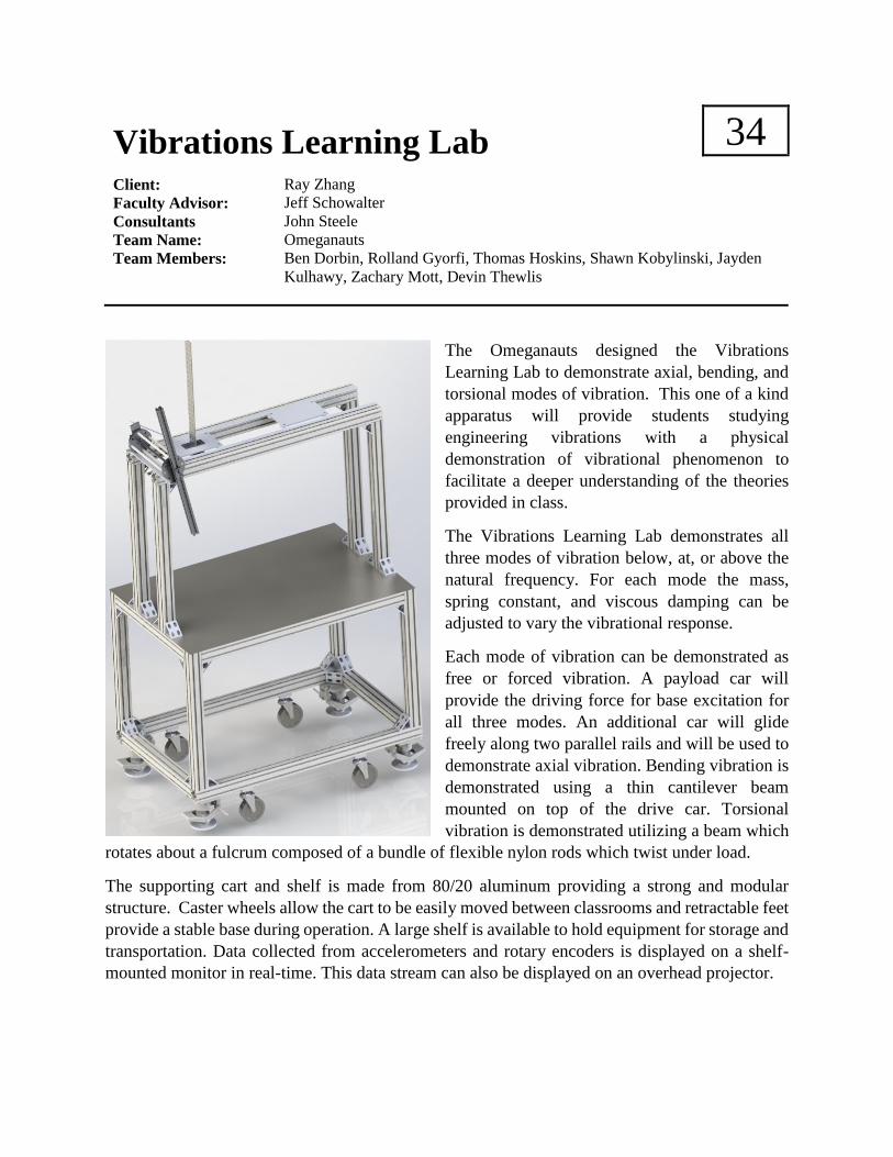
The Omeganauts designed the Vibrations
Learning Lab to demonstrate axial, bending, and
torsional modes of vibration. This one of a kind
apparatus will provide students studying
engineering vibrations with a physical
demonstration of vibrational phenomenon to
facilitate a deeper understanding of the theories
provided in class.
The Vibrations Learning Lab demonstrates all
three modes of vibration below, at, or above the
natural frequency. For each mode the mass,
spring constant, and viscous damping can be
adjusted to vary the vibrational response.
Each mode of vibration can be demonstrated as
free or forced vibration. A payload car will
provide the driving force for base excitation for
all three modes. An additional car will glide
freely along two parallel rails and will be used to
demonstrate axial vibration. Bending vibration is
demonstrated using a thin cantilever beam
mounted on top of the drive car. Torsional
vibration is demonstrated utilizing a beam which
rotates about a fulcrum composed of a bundle of flexible nylon rods which twist under load.
The supporting cart and shelf is made from 80/20 aluminum providing a strong and modular
structure. Caster wheels allow the cart to be easily moved between classrooms and retractable feet
provide a stable base during operation. A large shelf is available to hold equipment for storage and
transportation. Data collected from accelerometers and rotary encoders is displayed on a shelf-
mounted monitor in real-time. This data stream can also be displayed on an overhead projector.

Fluids Teaching Laboratory 35
Client: Dr. Nils Tilton
Faculty Advisor: Dr. Greg Jackson
Consultants Dr. Derrick Rodriguez
Team Name: The Jackson VI
Team Members: Lucas Christian, Curt Colburn, Karvel Haug,
Albert Nguyen, Daniel Petree, Matt Swanson
The Jackson VI is proud to present the Fluids Teaching Laboratory to be used in conjunction with
Colorado School of Mines fluids courses. The client of this project requested the design and build
of a laboratory that introduces students to
hands on experience with curriculum
fundamentals. Further, the client wished
for the laboratory to go beyond traditional
fundamental experiments and introduce
students to real, complex, industry
challenges.
The Jackson VI has successfully designed
and constructed a laboratory that
effectively meets the client’s demands.
This rig is a goliath, measuring eight feet
tall by twelve feet long and utilizes clear
pvc piping so that students can visually
observe the phenomena they are
experimenting with. The rig has the
ability to run single phase (water) as well
as two-phase with CO2 injection. The rig
uses LabVIEW, a data acquisition
software, to communicate with various pressure transducers, automated valves, and pumps so that
students get hands on experience gathering data and controlling a live fluid network.
Along with the rig itself, the Jackson VI has developed a series of experiments to be performed by
the students that are focused on the concepts and fundamental learned in their Fluids I & II courses.
This laboratory goes beyond the traditional fluid experiments and gets students excited about
learning!
Experiment Rig 1

Fluids II Lab Development 36
Client(s): Dr. Derrick Rodriguez
Faculty Advisor: Dr. Greg Jackson
Consultants Dr. Nils Tilton
Team Name: Smart Drops
Team Members: Brandi Fruge, Noah Langford, Antonia McMullan,
John Nguyen, Kellan Richard, Spencer Tryba
Smart Drops has been presented with the challenge of creating a fluid flow loop for future
undergraduates to expose them to complex flows that often occur in industry. With the final
deliverables of a fully built flow loop and an
accompanying manual for the use and management of
the loop. Smart Drops has chosen the challenge of
producing slug flow, essentially bubbles that produce
large pressure spikes in many piping systems that use
two phase flow. There are larger flow loops that have
been able to achieve this, however Smart Drops is
required to shrink down the scale to a size that fits into
a room. The largest challenge in this project is to be
able to shrink the size of the flow loop while
maintaining the physics necessary to produce a slug.
The solution was to take many of the papers written on
the larger flow loops and use the data, primarily the
unitless data on superficial velocities to find the proper
height needed for the vertical test section to produce a
slug with a given diameter. Another focus was placed
on visualization to aid in student learning. To
overcome this concern, a clear test section with the
pipe diameter of 3” was chosen, so that students can
clearly see the multiphase flow. Along with the main
focus of multiphase flow, the pipe system has been
designed for other experiments to ensure a more robust
student learning including multiple concepts from the
fluid dynamics courses that are offered at Mines.
Assembly of Flow Loop Design

Continuous Tabletop Research Glass
Melter
37
Client(s): Dr. Ivan Cornejo
Faculty Advisor: Dr. Yitz Finch
Consultants Dr. Steven DeCaluwe
Dr. Geoff Brennecka
Team Name: F14-37
Team Members: Alexander Cerny, Joelle Marshall, Nathaniel Marshall, Sarah Pekarek, Tyler
Johnson, Daniel Devers
In the materials lab, here at the Colorado School of Mines, numerous professors want to perform
research on glass. However, they are limited to only making glass utilizing a batch melting system.
This current process does consistently create glass, but the glass created doesn’t have the same
mechanical properties as glass created by industry melters. Because of this difference, any research
done on the glass made at Mines is essentially irrelevant to the real world.
In order to rectify this situation, it is our team’s responsibility to design a melter that emulates
industry melters. Since industry melters can be up to 1/3 of a football field in size, scaling them
down creates some additional complexity in the project.
In order to ensure that our melter design functions like an industry melter, we identified the key
metrics to be designed to. Temperatures in the various stages of the melter must match the
temperatures maintained throughout industry processes. Additionally, glass moving through our
melter should follow the same steps as in industry. The steps of industry glass melting are
highlighted by the image below:
Our team has performed several hand calculations and thermal analyses through SolidWorks to
demonstrate that our melter design will accurately emulate industry melters and produce glass with
similar mechanical properties.

Off-Axis Micro Coil Winder 38
Client(s): Medtronic – Tom Cilke & Greg Smith
Faculty Advisor: Dr. Chuck Reynerson
Consultants Dr. William Hoff
Team Name: Off-Axis Micro Coil Winding Team
Team Members: Devin Jorstad, James Morris, Luke Pepperl,
Kyle Moore, Marvin Ruiz-Ibarra, & Michael Schuster
The aim of the Off-Axis Micro Coil
Winding Project is to design a coil
winding machine that wraps three
coils of 50AWG wire around a stylet
off-axis relative to its central axis.
Stylets are surgical tools that are used
in medical imaging using
electromagnetic (EM) waves in order
to pinpoint a location in space. These
stylets are used by surgeons to perform
less invasive surgeries by allowing
them to guide medical instruments
through small incisions in the patient’s
body.
Medtronic currently has the ability to
wind coils that are perpendicular to the
stylet which allows for 2D location; however, they want to move to using coils that are wound off-
axis. Having three coils that are wound off-axis will enable higher resolution imaging with 3D
location.
One of the challenges of this project is to create a method for keeping the coil off-axis from the
stylet. This is difficult because under tension the wire will slide to the perpendicular position on
the stylet. Another challenge is finding a technique for winding coil that is 50 AWG in size because
it is approximately 0.0251mm in diameter, which is thinner than a strand of hair.
Our team has currently developed what is known as a toroidal coil winder. This type of winder
uses the rotation of a shuttle to lay the wire onto the stylet. The winder also uses linear actuation
to move the stylet to the desired position while the shuttle rotates to wrap the coil around the stylet.
Figure 1: Stylet Coil Winding
Figure 2: Coil Winder

Olympic Trampoline Measurement System 39
Client(s): Dr. Mounir Zok, United States Olympic Committee
Faculty Advisor: Dr. R. D. Slovikoski
Consultants Dr. Joel Bach
Team Name: Jump Around
Team Members: Nathalie Bram, Jed Braun, Andy Miller, Ross Sagehorn,
Michael Werner, Colt Wilkins
The sport of Olympic Trampolining
features a number of metrics that
can influence an athlete’s score.
These metrics include the athlete's
landing position and the total time
of flight (ToF) for the athlete's
routine. Accurately measuring these
metrics during training will put
coaches in a strategic position to
provide their athletes with objective
feedback based on data, rather than
relying exclusively on video and
coaches’ expertise. With this in
mind, the United States Olympic
Committee (USOC) has tasked our
team with producing a measurement system for the trampoline event. Specifically, Team Jump
Around is responsible for delivering a system capable of measuring an athlete's ToF, jump
height, and landing position. This system must also record video footage of the jumps and
provide the specified information in real-time.
Jump Around's measurement system uses 9 Idec type SA1E-TN2-2M photoelectric sensors
(placed below the trampoline bed) to gather data. ToF is measured as the time between sensor
trips and will be used to calculate jump height through simple kinematics. The order in which
individual sensors are tripped can show if the athlete landed inside the trampoline's deduction
box. This information is supplemented by video footage gathered by a Muhi Veho K2 camera,
which provides adequate detail for slow-motion video replay. This data is stored in a database,
and an easy-to-use GUI will display time of flight and position deduction information in real
time along with post-event replay.
Prototype development has included subsystem/full-system tests at actual trampoline training
gyms. Results have been compared to those produced by commercially available measurement
systems to ensure that our system can provide comparable data in training scenarios.

Athelete Instrumentation Project 40
Client(s): Dr. Mounir Zok, United States Olympic Committee
Faculty Advisor: Dr. R. D. Slovikoski
Consultants: Dr. Joel Bach, Dr. Anne Silverman
Team Name: Peak Performance
Team Members: Chris Hayes, Geoff Sowash, Jessica Lyon, Graeme Smith, Cory Carter, Zane
Perez
The purpose of the Athlete Instrumentation Project is to help the US Olympic Men’s Gymnastics Team
with their performance on the Pommel Horse event. We are exploring the use of small, wireless, body
mounted Inertial Measurement Units (IMUs) to allow the coaches to easily and accurately quantify rhythm
and pacing. In this project we built Matlab software that displays, processes and stores IMU data in a simple
and useful way.
Traditionally coaches have had no quantitative way to track rhythm in a routine (other than simple video
recording). Our system focuses on the circle type movement on the pommel horse and allows easy
measurement of average and individual circle times in a routine.
The hardware we are building our software on top of is the APDM Opal IMU system. This hardware and
software package is relatively inexpensive and gives accurate triaxial accelerometer, gyroscope and
magnetometer measurements at 128 Hz. It also offers simple wireless data collection (in our case with up
to 5 IMUs) and 10 hour battery life. To detect when an athlete completes a circle we analyze magnetometer
data, which shows clear cyclic variation as the IMU rotates through the Earth’s magnetic field.
The final design package consists of a working prototype instrumentation system including our MatLab
software, design documentation, code documentation for future development, and system validation tests.
Figure 1: Main user interface window
Figure 2: Typical pommel horse routine

Individual Broader Impacts Essay
This semester all Senior Design students were assigned to write and submit an individual, 1500
word essay about how their engineering choices impact the social, environmental, and/or economic
lives of communities and individuals. The topic for this semester’s essay is:
As a practicing engineer you must “design within constraints.” While most engineers gravitate
toward the technical constraints, there are often social, environmental, and/or economic
constraints as well. For example, how do you design a wind installation to achieve targeted
output, minimize its environmental impact, and maximize social acceptance? Present a
discussion, using an example, of engineers designing within a complex mix of technical, social,
environmental, and/or economic constraints that is either related to your project or your field of
engineering.
The top 13 essays from this semester’s group of 250 senior engineering students were chosen by
the course faculty and are included in the Program in alphabetical order.
Essay Title Author
Broader Impacts: The Challenge of Engineering in the Modern World Steven Avetissian
Hoover Dam Bypass Michael Campbell
Genetic Modification and Your Food Kathryn Duvall
Engineering Design Constraints: Social, Environmental, and Economic Lindsey Freytag
Inspiring Change Katherine Herrera
Gazing Skyward Brent Last
A New Direction in Restoration Jessica Lyon
The Helicopter Dilemma: Safety Not Guaranteed Zachary Mott
Hydraulic Fracturing – An engineering advancement being halted in any
way possible
Lauren Revis
An Integration of Many Factors Kenneth Schultz
Desalination Plants Worth Their Salt? Katharine Sexton
The Broader Impacts of Electronics Manufacturing Geoffrey Sowash
Designing the Frederic C. Hamilton Addition to the Denver Art Museum Kevin Trautman
The top three essays have been judged by a panel of volunteer judges and winners of the best essay
contest will be announced along with the Trade Fair results. This year’s judges were:
John Agee Brenda Chergo Caitlin Ewing
Sarah Gilmore Hans Hoppe Jamie Jackson
Steve Kutska Valeriy Maisotsenko Lily Nguyen
Art Pansze Anthony Petrella Eric Phannenstiel
Charles Speltz Kim Vo Ken Witherell
We thank you very much for your time and effort involved in choosing the top essays!


Broader Impacts: The Challenge of Engineering in the Modern World
Steven Avetissian
Any young engineer must learn the difference between practical and theoretical design
work. That is, engineers must learn what it means to design a product within the various economic,
social, and environmental constraints that exist in the real world. Engineers still in school often
neglect these important factors and focus solely on the technical constraints of a project. This can
lead to misinformed designs that will not operate successfully under real world conditions, or
worse yet will never be fully developed due to consumer backlash. The challenge of balancing
technical constraints against the various other economic, social, and environmental constraints is
one that all engineers must be prepared to face. How well the challenge is met can often determine
the success or failure of a product.
In any type of design work, the very first question any engineer must ask themselves is
“what problem am I attempting to solve?” The design process must always begin with an accurate
description of the problem. This ensures that the engineer does not neglect important details nor
include extraneous information. The definition of the problem must be accurate and concise while
leaving enough room for the exploration of multiple solutions. This stage of the design phase is
critical because it is the foundation for all other aspects of design. Without a proper problem
definition, it is impossible to continue through the design process.
Once the problem has been properly defined however, the engineer may move on to
identifying all known information about the problem. It is in this phase that the engineer must
begin considering constraints outside the technical realm. All available information about the
problem must be taken into consideration. In the context of economic constraints, the engineer
must consider first whether or not the problem can be successfully solved with the allocated
budget. Money is one of the most important factors in the design process and engineers should
always design with economic constrains in mind. In this early stage of the design process it is
important for the engineer to make estimates about the total cost of the project. The engineer must
not only consider actual dollar values but also factor in cost in terms of man hours to completion
and other valuable company resources. The next bit of information an engineer must consider, in
regards to the problem, is any available information regarding the environmental impact. In this
stage it is most valuable to conduct extensive research on the problem. This research can also help
shed light on the social constraints of the design process. When brainstorming possible solutions

to a problem, the engineer must keep in mind how the design will affect (if at all) the local (or
perhaps global) ecosystem. Questions should be asked regarding the plant and animal life in the
area, the type of waste produced by the construction and operation of the product, the impact on
the various natural resources of an area, etc. All of these questions must be answered, at least in
part, before the company can decide to spend more money on the design and development of the
product. Similar questions must be asked about social constraints as well. The engineer must
conduct research to determine if there is demand for such a product, how the public will react to
such a product, does it have any unintended health effects, etc. The answers to these questions are
just as important to the success of the design project as the environmental constraints. Economic,
environmental, and social constraints go hand-in-hand. Often time’s one constraining factor drives
the other constraints. If more money can be allocated to the project then it is easier to include more
social and environmental constraints to the process. If environmental or social constraints are
paramount, more money may be allocated to meet those constraints. Conversely, if environmental
and social constraints are not as important, less money may be allocated to the project. This early
phase in the design process is crucial. Any information neglected here may cause problems for the
design team later in the future.
The next phase in the design process is to make all the necessary assumptions and justify
them. Here again, many of the same constraints that needed to be considered in the information
gathering phase must be considered in this phase. Making the appropriate assumptions about the
project is vital for designing a viable technical solution to the problem. But these assumptions must
include assumptions about the economic, environmental, and social impact of the product as well.
For example, if the product is going to generate some type of waste, assumptions need to be made
about the quantity of waste produced, the usefulness of such waste, and what is to be done with
said waste. Additionally, one must make assumptions about the social impact of a product.
Engineers should make assumptions regarding the effect of the product on local populations. These
assumptions can include things like increasing the available jobs in an area, bringing increased
revenue to an area, etc. Making the proper assumptions about the design in question is remarkably
important for determining the success of any design project. Companies have often been vilified
for making incorrect assumptions about a product. Of course the validity of any assumption should
be verified and this is often where the information gathering phase (the phase prior to the

assumption phase) is most valuable. In the next phase of the design process, all the constraints of
the project must be accounted for in order to avoid failure.
The next phase of the design process is the phase that most engineers are familiar with. The
actual design and test phase. This phase of the process is almost wholly determined by the
information collected in the previous three stages. The design must solve the problem attempting
to be solved. The success of this is determined by how thorough the information gathering was
and how accurate the assumptions were. Often times this is the most time consuming and expensive
phase of the design process because it is here that the unexpected must be accounted for. For
example, if the one of the assumptions made was that the product would produce a certain kind of
waste and the product actually produces a different kind of waste, money must be invested to
reevaluate and modify the original assumptions. Of course, the obvious technical constraints are
considered heavily in this phase as well. Technical constraints often force engineers to reconsider
aspects of the design. This can lead back to square one as a whole new problem might need to be
defined and solved before progress can be made on the one already started. This phase of the design
process has obvious technical and economic constraints but the engineer must not overlook the
environmental and social impacts of the design and test phase as well.
It is in the final phase of the design process that a complete picture of the product is formed.
During the implementation phase of the design process, the product must solve the problem it was
originally intended to solve while still operating within the various economic, environmental, and
social constraints that were originally placed on it. Is the product sustainable within these
constraints? It means very little to successfully install a new wind turbine if the wind turbine is not
going to produce enough energy to pay off the investment of installing it, or if the environmental
impacts force further investment of resources, or if the surrounding population hates it demands
its removal. This is why the information and assumption making phases are so crucial and why it
is especially important to consider all of the constraints during these phases. The long term success
of the project quite literally depends on the engineer’s ability to design within all of the present
constraints.
The design process is not an easy process. It is costly in both time and resources. When an
engineer begins the design process, there is no guarantee of success. However, by ensuring that
the engineer has a good understanding of the various constraints of the project and keeps those
constraints in mind throughout the design process, the chances of success can be increased

exponentially. It is always important to consider the economic, environmental, and social impacts
of a design throughout the design procedure. This is something very hard to teach in an academic
setting and is something that must be learned in a practical work environment. This is one of the
first and most valuable lessons all young engineers entering the work force must learn. Once the
lesson is learned, the possibilities are boundless.

Hoover Dam Bypass
Michael Campbell
Engineers tend to different perspectives of the world than most people. Engineers tend to
look a structure, a road, a machine, and think about how it works, and why it works. They then use
math and science to prove the how and the why. A progressive idea is created and the engineers
are the force that makes it a reality. At first glance, the work of engineering is considered to be
very science and math intensive regarding the safety and workability of a design. The public and
even most engineers view themselves to be masters of in technical analysis for their field of
practice. Therefore, engineers tend to gravitate towards the technical aspects and disregard the
social and environmental aspects that affect a project. From a fourth year college student in civil
engineering, many technical aspects are involved in order to design and build dams, roadways, and
bridges. For the bridge alone, engineers must take into account, the physical design of the bridge,
the material that the bridge is made of, the connections, the anchoring to the ground, and the many
different loading situations. There is a great amount of technical work that goes into designing
anything in the civil application. But the following example of the Hoover Dam Bypass displays
how civil engineering projects consider social and environmental aspects.
The Hoover Dam was built in the 1930’s and is still one of the greatest civil engineering
projects today. Over the years, the Hoover Dam became a hot spot for visitors to stand on top of
its greatness viewing the canyon and Lake Mead. U.S. Route 93, the highway that passes through
the dam and a major connector between Nevada, Arizona, and Utah, is a four-lane highway that
reduces to a two-lane highway to get up and over the dam. Because of the major traffic rolling
through this area due to tourism and general thru traffic, the canyon became a huge bottleneck for
travelers and mostly truckers. Since 1964 there has been more than 500 crashes on the windy
canyon road, in which one fifth of them included trucks. The Hoover Dam is a major supplier of
hydroelectric power to Southern California, and if there were to be an accident on the dam, millions
of human lives would be impacted for the worse. Also, a crash on the dam involving hazardous
material could seriously impact the quality of the water flowing in the Colorado River. The
Colorado River is also a major water supply for the many surrounding states. Therefore, in the late
1980s and early 1990s, many bypass projects were presented to fix this problem [1].
In order to execute the Hoover Dam Bypass project, the U.S. Bureau of Reclamation
working with the Federal Highway Administration (FHWA) must consider the wildlife impact that

the construction of the bypass would impose on. Any bypass option seems that it would impact
the ecosystem of the surrounding Mojave Desert, including the habitat of the bighorn sheep and
the desert tortoise. At this point in the early 1990s, three proposals were made in order to execute
the construction of the bypass. There was the “Promontory Point” option, which included
constructing a bridge upstream from the dam and imposing little environmental impact. The
second option was the “Sugarloaf Mountain” proposal that consisted of constructing a bridge
downstream of the dam, and imposed the least amount of environmental impact. The third option
was the “Gold Strike Canyon” proposal which also consisted of building a bridge further
downstream of the dam, and affected the environment the most out of the three options. The “Gold
Strike Canyon” project would significantly increase the noise and take away more area from the
wildlife than the other two projects. It turns out, that none of these options were executed at this
time due to the lack of funding for environmental studies. Therefore, the project was put on hold
[1].
In the late 1990s, the congestion crossing the dam became too much for travelers and
something needed to be done. Two more proposals were created for the Hoover Dam Bypass and
both these proposals were rejected due to environmental or social impacts. One of the proposals
consisted of adding 36 kilometer of new high highway that would relieve trucks from flowing
through a town in Boulder City, Nevada but would prove to be more expensive and damaging to
the environment near the Lake Mead National Recreation Area. Therefore, this idea was thrown
out. The other proposal consisted of mostly using existing roads, but adding a 37 kilometer detour
around the dam through steeps grades. The social effects of this proposal were its downfall [1].
After about of decade of decision making, trying to comply with the environmental and
social aspects of building the Hoover Dam Bypass, a proposal was selected in 1998. The FHWA
ended up selecting the “Sugarloaf Mountain” proposal, which consists of 5.3 kilometer of new
highway, and 580 meter cable-stayed or steel truss bridge located 460 meters downstream of the
Hoover Dam. This option received the most support from the public and from local, state, federal
agencies. This selection also had the least impact on the environment in regards to the habitat of
the bighorn sheep and the desert tortoise because of its lack of impact on Lake Mead and the
drinking water supply for the surrounding states. Before completing the project, the FWHA will
have to devise a mitigation plan that minimizes the effect on habitat used for migration or mating,
replace lost habitat, include erosion control and storm water runoff plans to comply with the

environmental impacts of the bypass. The technical aspects of the “Sugarloaf Mountain” project
presumed to be the safest of any of the other proposals because of the lower grades and eliminating
curves at the ends of the bridge. Construction started in 2002 and the bypass finally opened in 2010
[1].
The technical aspects in respect to the Hoover Dam Bypass were the least of the worries in
the decision process of execution. The social and mainly environmental effects were the governing
factors for completion of this project. Even though engineers tend focus more on technical aspects
of a project, the social and environmental impacts are just as important. It is crucial that engineers
step back from the calculations and take in the bigger picture of a situation. Without environmental
and social constraints, Mother Nature itself might as well be a thing of the past considering the
direction society is heading towards. Technology is a major part of developing the human race,
but the human race is part of nature and must comply with preserving the environment that humans
live in.
Reference:
[1] T. Haussler and D. Rekenthaler, “The Hoover Dam Bypass,” Public Roads, July/August 1999
Vol. 63 No. 1 [Online]. Federal Highway Administration.
<http://www.fhwa.dot.gov/publications/publicroads/99julaug/hoover.cfm>.


Genetic Modification and Your Food
Kathryn Duvall
As engineers, it is our duty to examine the long-term and widespread effects of any project
we are a part of. This includes, but is not limited to social, technological and environmental
impacts. No such project has a greater influence on these areas than genetically modified
organisms (GMO) in food products. There are few technological and scientific advances that have
made such a stir as the GMO industry. This essay will delve into the details of the social, economic
and environmental effects of this biotechnology. Before getting into these details, it is important
to understand what GMOs are and why they exist.
For as long as there have been humans on Earth, starvation has also existed. The shift from
a hunter-gatherer to an agricultural species was a great help in making sure that more people got
food. But where there are farms, there are pests, plagues and draughts to threaten the vitality of
these crops. Beginning around the turn of the 20th century [1], farmers began heavily relying on
chemical pesticides, mainly DDT, to protect crops from detrimental insect damage. Then in 1962,
Rachel Carson published “Silent Spring,” displaying for the public the dangers of these chemicals
when consumed by humans. In order to economically grow mass amounts of food, something else
had to be done. So, in 1980, the first patent for a genetically modified organism was issued, and in
1982, the FDA cleared the first GMO [2].
With genetic modification, crops are now inherently resistant to insects. Another benefit is
that these foods now have a longer shelf life, as they are being modified to ripen and decay at a
lesser rate than their non-modified predecessors.
With this base knowledge into the history and purpose of GMOs, the large-scale impacts
must be examined. The first major area that is influenced is society. Here in the United States,
there is a lot of debate about everything we put into our bodies. Should it be organic? Should we
be eating gluten? What are the risks of vaccines? GMOs are no different. There are those who
argue that these modifications are unnatural and therefore unsafe for human consumption, however
all GMOs on the market today have been approved by both the FDA and the EPA, which have
stringent safety standards. Most standards set by the EPA are in fact much more strict than is
required, to stay on the safe side.
With a longer period of freshness and resistance to insects, foods grown in certain areas of
the globe are more easily distributed over longer distances. This is a vital step forward in a world

where so many people go hungry and die of starvation. If producing areas are able to get food to
far reaches, more people will have access to it. These new crops are also easier to grow. A farmer
who cannot afford to protect his crops with pesticides can now use these GMOs in order to have a
higher yield from each harvest. This is vital for those in developing countries. Genetic modification
of food products can also make these foods more nutrient-rich. In countries where food is scarce,
getting the largest possible nutritional value out of food is of the utmost importance. GMO crops
are allowing for crops that yield more food, which in and of itself has a higher nutritional yield.
Without using harsh chemicals that are damaging to the environment, GMO crops are an incredibly
sustainable way to farm.
A negative social effect can also be found for farmers who do not wish to use GMO
products. There have been many lawsuits by biotech companies, most famously Monsanto, against
farmers whose crops have cross-pollinated with biotech crops. Because the modified DNA is a
patented product, their use is restricted to those who have paid for it. Plants are naturally designed
to propagate largely on their own, so wind, insects and birds can contaminate a non-GMO crop
with a neighbor’s patented crop. Fortunately, corn cannot reproduce without human intervention,
so the most important grain in America is unaffected. Many argue that this is hurting the American
farmer and therefore the American economy.
The economic impacts of GMO foods cannot be ignored. In the US and abroad, these
biotech products are causing quite a stir, as mentioned in the previous paragraph. Since the EPA
has a requirement for ethanol in gasoline, the corn industry is absolutely critical. According to a
study completed by Iowa State University, if it weren’t for biotechnology, global prices for corn
would be 6% higher than what they are today [3]. People who oppose GMOs have implied that
since these crops are patented, that the seeds have a higher cost than the non-biotech versions. This
may be true up front, but clearly studies have shown that the cost for maintenance, combined with
the higher yield per harvest actually causes a net savings. The case for corn is that we use it so
much in our everyday lives that these savings are not only on the price per bushel. There are a
wide variety of corn products, from other foods to biodegradable flatware, and it is absolutely
indispensable to the economy of the US. Making these products more accessible, both domestic
and abroad, helps keep America afloat.
As mentioned in the discussion of social impacts, farmers all over the world are finding
economic benefits from GMOs. A smaller patch of farmland may still produce a large quantity.

Since the same plot cannot be reused every year due to soil nutrient depletion, even using a portion
of land may return more than non-GMOs would, using the entire area. Having a longer period of
freshness also means that a season’s growth will last. These growers do not need to use a pesticide,
which, in turn, saves money with every harvest.
Farmers are not the only people to experience the benefit of not using pesticides. The
environmental impact of GMOs cannot be ignored. As previously mentioned, the primary way to
protect crops from insects without GMOs is pesticides. The pesticide most commonly used is
DDT. DDT has been shown to have a wide variety of negative effects. It is toxic when consumed
and, starting with insects and plants, this toxicity makes its way up the food chain. The saying,
“you are what you eat,” includes these harsh chemicals. By taking these chemicals out of the
ecosystem, any unintended targets can now thrive. A study has shown that the decline in the use
of pesticides has led to an increased population of the natural predators, like spiders and ladybirds,
of the herbivorous insects that wreak havoc on crops. If the natural predators are more prevalent,
it reduces the population of these insects [4]. This strengthens local ecology in another way as well.
Every predator is prey to other animals, and the increased population of prey sustains predators.
As GMOs gain momentum, there is also the chance of creating plants that can grow in
environments that are not conventional farmland. For instance, geneticists are working on plants
that can grow in the San Joaquin Valley, which has notoriously high salinity [5]. This and other
previously uninhabitable areas may, in the future, be used for various crops. More plants will have
positive effects on the environment, because they consume CO2 and produce oxygen. This will
also help offset the rapidly growing world population.
The use of biotech crops helps to reduce land area required for the same yield as traditional
seed. This helps to reduce CO2 emissions. The low maintenance quality of GMOs produces the
same result. Farmers do not need to use heavy equipment to treat the fields as often or as
intensively. With traditional crops, farmers must till the soil to keep the nutrients fresh. This
releases CO2, which is generally trapped within the soil and used to help the plants grow. Studies
have show that in 2009, biotechnology helped reduce emissions by 39 billion pounds [3].
The purpose of GMOs is to create very broad impacts, but the extent may not have been
fully anticipated. Although engineering projects and products are primarily developed in order to
benefit the world, every point has a counterpoint. There are many, especially in the scientific
community, which hail the benefits of GMOs. The ability to artificially alter the DNA of a living

thing opens the door to endless possibilities for genetic engineering, which is a very exciting step
forward. Supporters say that this is science speeding up the process of natural selection, while
opponents argue that this is tempting fate.
Whatever your view of GMOs, it is undeniable that they have made their mark on the
course of global history. With any great technological advance, there are many costs that come
with each benefit. It is the job of responsible engineers to weigh these and make a decision that
will hopefully impact the world in a positive way.
References:
[1] Muir, Patricia, A History of Pesticide Use, Oregon State University:
http://people.oregonstate.edu/~muirp/pesthist.htm
[2] GMO Inside: http://gmoinside.org/gmo-timeline-a-history-genetically-modified-foods/
[3] Common Ground, Conversations about Farming and Food:
http://findourcommonground.com/food-facts/gmo-foods/
[4] Carrington, Damian, The Guardian:
http://www.theguardian.com/environment/2012/jun/13/gm-crops-environment-study
[5] Edwards, T., Faerber, J., Goenawan, A., Osawa, S., Genetically Modified Foods:
https://classes.soe.ucsc.edu/cmpe080e/Spring05/projects/gmo/benefits.htm

Engineering Design Constraints: Social, Environmental, and Economic
Lindsey Freytag
For any design challenge, there will be constraints that will guide the design process. These
constraints can fall under four categories: technical, social, environmental, and economic.
Typically, technical constraints are the most significant priority for engineers to design according
too. However, the last three are equally as important, especially in the field of environmental
engineering.
As an environmental engineer, everything I design, analyze, or evaluate always gravitates
toward the environment. Everything I do is geared towards protecting or restoring the
environment; this will be a constraint on anything I do with my career, whether that be treating
wastewater for safe release into the environment or remediation of contaminated sites to restore
the environment to it’s original, healthy condition or investigating permit and compliance issues
in industry. So the design and consideration of environmental constraints is nothing new or
groundbreaking to me. Additionally, economic constraints are very well ingrained into every
engineer’s mind that it’s not really worth being the focus of this essay. Cost is typically the bottom
line. An example: if a new regulation is being imposed on a wastewater treatment facility that
restricts the phosphorous levels in the effluent from the plant, there is a certain point where is it
more cost-effective to violate that permit and pay the fine than it would be to input a new system
for more efficient phosphorous removal. For this example, the economic constraint is that the new
phosphorous removal system must be cheaper than the cost of violating the permit. This is why
cost analyses are always ingrained into every design project we have at this school.
So the point here is that most engineers are aware of environmental or economic design
constraints. What is often forgotten, however, are the social constraints of design. There are many,
many examples of situations where engineers design something without considering how it’s
intended use will impact the people it is being designed for.
One example of this came as part of a TED talk by Liz Ogbu called “Why I'm an architect
that designs for social impact, not buildings”. In many southern, poverty-ridden areas, a common
obstacle for many people is cooking. The typical method involved using a three stone fire to prop
up a metal cooking pot over the wood fire. Several problems arise from this method; smoke
inhalation by the user, fuel usage and resulting deforestation, and air pollution. In response to this,
a global initiative has already taken action and designed a solution. This solution is a cook stove

that is fueled by coal. Liz was working on a design project for these regions when she came across
the astounding fact that even though many people own these “cook stoves”, they rarely use them
enough to actually reap the benefits from them. Her next step was to investigate why, and what
she found was that the women who used them often complained that they were more of a hassle
to use than the original method, especially if they needed to cook large quantities. Additionally,
the cost of fuel (charcoal) for a month was more expensive than a year’s worth of wood for fuel.
This is one example where an engineering solution was designed without the social impacts in
mind.
The solution fit all of the technical design constraints: it efficiently and safely allowed it’s
users to cook a meal. It fulfilled all of the environmental constraints: it utilized a fuel that would
slow the rate of deforestation, reduce air pollution, and reduce negative health impacts of smoke
inhalation. It fulfilled the economic constraints: it was affordable enough that most people in these
areas could attain one. It did not, however, fulfill the social constraints. Because of the lives these
people lead, they could not afford the increased fuel usage. So what good did this solution really
do for the people it was intended for?
Examples like this occur frequently and globally. There needs to be a bigger initiative to
include social aspects and impacts as constraints for engineering projects. This could be a potential
challenge however. It requires much deeper insight into the intended user audience. This can often
be hard for engineers who are designing for different classes, social groups, or cultures. Another
good example of this comes from the movie “Urbanization”, which discusses a subsidized low
income housing project in Lo Barnechea. The engineers and decision makers had a certain budget
to provide the most essential necessities of a house and there was not enough for both a bath tub
and a hot water heater. So the decision makers (the engineers and politicians) were given the
choice, and most would instinctively have chosen a hot water heater to supply shower water. But
potential residents always preferred the bathtub. This is because they came from a life where a
shower meant a bucket of cold water and a hot water heater would meant a gas bill that they
couldn’t afford. This is just another situation where engineers and the people in charge of these
decisions did not have all of the information in front of them to make the best educated decisions
based on the social constraints.
I have taken one class here at CSM that really digs deep into this issue, Sustainable
Engineering Design. A lot of the discussion in this class involved social impacts and what role

designing for sustainability played. A large focus was put on Social Life Cycle Assessment
(SLCA) and using this type of analysis to evaluate the social impacts of a product throughout its
entire life cycle, or from “cradle to grave”. This type of analysis can identify social “hotspots” in
a product lifecycle; these hotspots are places that have significant social impacts. SLCAs can
identify positive impacts as well. SLCAs can include factors such as human rights, working
conditions, health and safety, cultural heritage, governance and socioeconomic repercussion [3].
This type of analysis could be incorporated into design projects here at CSM in order to help teach
social responsibility and designing for social constraints. As trouble spots are identified, the
process or product can be modified for improvement. This makes it an iterative process and an
effective process for analyzing social impacts.
Social, environmental, and economic constraints are often extremely interconnected,
especially in the field of environmental engineering. As with the example stated earlier, sometimes
economic constraints take priority over environmental or social constraints when protecting the
environment becomes too costly to be economical. There is currently a growing problem involving
the regulation of environmental levels of the active ingredient in common birth control pills. This
is an extremely important example of how the social, environmental, and economic constraints are
all so interconnected. Ethinyl Estradiol (EE2) is an active ingredient in many common forms of
birth control; as such, it is excreted from the female body into wastewater effluents which are then
released into the environment [4]. This chemical is highly damaging to wildlife and effluent levels
in wastewater are not yet regulated or controlled. This chemical is causing serious damage to the
reproductive abilities of aquatic wildlife. Yet a main concern lies in how to regulate this chemical
in wastewater and who should bear the cost, the public or the pharmaceutical companies that
produce it? As it is, the problem is exacerbating as the debate drags on about how to proceed
because it would be very costly to treat and regulate wastewaters for this contaminant. This
dilemma has an important social aspect as well, another potential solution would be to vary forms
of birth control to avoid EE2, but what impacts would that have on females? Would there be
unforeseen consequences such as rising costs of birth control and a consequential rise in unplanned
pregnancies? What kind of implications would this have for poverty-stricken females who might
have no alternatives? These are all important constraints that need to be considered in complex
environmental problems such as these.

In many engineering projects the social, environmental, and economic constraints are often
considered with less importance. As explored in this essay, this can be potentially detrimental, as
in the case of EE2, or it can even negate the effectiveness of the engineered solutions, as in the
case of the cooking stove. Because many engineers are taught solely to focus on technical
constraints, this is where the problem arises. Not enough emphasis is placed on the considerations
of social, environmental, and economic constraints, even though these are all very vital
considerations in any design undertaking. The fact remains that social considerations still remain
the most ignored, and an important tool for correcting this situation could be the use of SLCAs.
All of the above examples are just a few of many about the challenge that any engineer faces in
designing to satisfy the complex combination of technical, social, environmental, and economic
constraints that are faced in our increasingly complex world.
References:
[1] Ogbu, Liz. "Why I'm an Architect That Designs for Social Impact, Not Buildings | Liz Ogbu |
TEDxMidAtlantic." YouTube. TED Talks, n.d. Web. 04 Mar. 2015.
<https://www.youtube.com/watch?v=x0MnGZ1gB4k>.
[2] Urbanized. Dir. Gary Hustwit. 2011. Netflix.
[3] "Social Life Cycle Assessment." Life Cycle Initiative. N.p., n.d. Web. 04 Mar. 2015.
[4] Owen, Richard, and Susan Jobling. "The Hidden Costs of Flexible Fertility."Nature 24 May
2012:

Inspiring Change
Katherine Herrera
Give me a truss. I can analyze it in more detail than you probably want. In less than 60
minutes, I can throw down a piece of E2 paper with so many numbers and equations you’ll know
more about that truss than you may have thought possible. I am a Colorado School of Mines
Civil Engineer; physics, thermodynamics, statics, and mathematical representations of physical
problems are my bread and butter. Give me a set of numerical constraints, and I can deliver a
numerically sound, efficiently engineered solution.
But what if the constraints aren’t numerical?
What if failure is not defined by the deflection of steel, or the cracking of concrete? What
if something was a true feat of engineering; a cost-effective, entirely safe, durable bridge
connecting one rural village to another? This bridge could connect communities, allow the
children from one to go the school in the other, allow for more collaboration, cooperation, and
exchange of information between the two cities. A beautiful feat of engineering that also brings
sustainable development, economic growth, and access to more opportunities to a developing
nation?
However, what if these two villages lived across a canyon from each other because they
were at war in years past? What if conflict had inflicted wounds that time was just beginning to
heal? What if this bridge was going to re-open those wounds, and spark a dispute that may last
many years into the future? Just because this bridge is a beautiful testament to engineering does
not mean that it will benefit the community.
The problem statements that are presented in classes are clearly defined. There are
specific constraints. The beam is fixed, or cantilevered, or pinned to some non-descript section of
a building. What the beam will be holding and who the structure belongs to is not considered, but
it should be.
Can I be an engineer that affects change, not only in the technological realm, but in the
social or environmental or economic realms as well? Can really I come from a world of analysis,
calculations, and math to enter a world of emotion, politics, and drastically varying cultures and
ideals?
Why not?

The seven wonders of the ancient world are all feats of engineering: the Hanging Gardens
of Babylon, the Great Pyramid of Egypt, the Statue of Zeus of Olympic, the Temple of Artemis
at Ephesus, the Mausoleum at Halicarnassus, the Colossus of Rhodes, the Lighthouse of
Alexandria [1]. Whether an enormous statue, pyramid, or building, the seven wonders were not
famous because of their function; they transcended history because they inspired wonder. They
captured the spirit of what was important during that time, such as the Greek gods, or the tombs
of ancient rulers. These engineers did not just build a functional lighthouse or statue, they took
into account the desires and priorities of the culture around them. They broadened their scope,
designed beyond the technical constraints.
My goal is not to build a monument for the glory of our current world leaders. The world
we live in does not appreciate gaudy symbols of power, and I have no interest in creating them.
However, like the designers of the ancient wonders, I don’t want to design for the sake of math
and the pursuit of knowledge. Instead, I want my engineering stamp on plans that enhance the
communities they’re designed for. Rebar and concrete suppliers should not be the only ones who
prosper from a bridge design. I want to frame the problem differently: non-numerical constraints
and non-technical results.
Small rural villages, however, are not the only places where non-technical concerns arise.
Take, for example, the 19th Street over 6th Avenue lid. This intersection was identified as an area
with high rates of pedestrian travel, accidents, and traffic congestion. What is the obvious
engineering solution? Build a bridge. This would keep traffic flowing across 19th, eliminate a
stoplight, and provide a safe path for pedestrians and cyclists to cross the highway. A bridge is
simple, straightforward, and elegant; any engineer would consider this problem solved. But is
this truly a good solution?
The City of Golden asked the residents of Golden this exact question with staggering
results. In three public meetings to discuss this project, the residents of Golden, particularly those
on the West side of 6th Avenue expressed support for the project, but not necessarily for the
bridge. Members of the community expressed many concerns and desires, but that one sticks out
the most: the worry this bridge would end up isolating this smaller western neighborhood from
the rest of Golden [2].
The realization that a bridge, of all things, would lead to potential division, led the City of
Golden back to the drawing board, this time looking to form a bridge between people, not places.

The result was the Lookout Mountain Lid. The new goal behind the bridge was to prevent people
driving, walking, or biking over 6th Avenue from noticing that they are moving over a highway.
With this new focus, the City of Golden once again opened up the floor to residents of Golden
who had an opinion about the lid, and got feedback that helped them pinpoint a design. Members
of the community expressed a desire for a dog park, and spoke out against sound walls and giant
statues that would block or disrupt the views [2].
The community feedback helped contribute to the final design, which drastically changed
from the initial plans. A simple bridge would have been more cost effective, and may have met
the basic safety and traffic flow concerns, but it also would have caused damage to the
community. Digging deeper and actively listening to the community allowed Golden to contract
Kraemer North America to move forward with a sustainable design that will not only improve
safety, but also give the city a better community.
I want to be the engineer that asks those questions; that discovers that not all villages get
along, and a park is often worth the investment. Looking beyond the soil samples and survey
points can provide a whole different perspective on the scope of the problem. I want to be the
engineer that finds the sustainable, effective, win-win solution to a given problem, not just the
most technically proficient. I want the plans I stamp to meet the real needs of a community, not
just the needs that I see first.
I want to have an impact on more than just E2 paper.
It’s why I chose to sign on with Kraemer. I didn’t just want any job when I graduated; I
want to make an impact on the communities I work in. When I step onto a construction site, I
want to make sure that the pier columns I’m inspecting will support a structure that the
community wants. At the intersection of 6th and I-25, Kraemer is demolishing and rebuilding
thirteen brides and widening 6th Avenue to improve the traffic flow. I learned that they were also
renovating three parks, and connecting them with a pedestrian bridge. People driving through the
worksite may not even notice the smaller bridges, but the community members do. This
neighborhood is the poorest area in Denver, and many people walk or bike to work, not able to
afford a car. This meant that safe parks located near these neighborhoods much more significant
and valuable to the community. The pedestrian bridge that crosses 6th Avenue allows community
members to avoid major streets and sub-par bike lanes. I want to work for a company that notices
this, that does not cut corners or ignore the concerns of the neighborhood.

I want to see the non-technical issues while solving technical problems. I want to have
time to stop and listen to community members, even while I’m measuring concrete forms I want
to work for a company that invests in the community; that sees the value in gathering non-
technical input. The parks, bridges, roads, lids, and infrastructure I build should bring sustainable
development, economic growth, and access to more opportunities to the communities I am
working in. The things I impact in life should not be limited to engineers and the technically
minded world.
I want to design the Lighthouse of Alexandria. Not literally, of course. I mean that I want
to be an engineer that builds for change, to spark inspiration. The plans I stamp should be more
than just incredible structural analysis. I want them to bring healthcare, education, fulfillment,
convenience, and justice sustainably to people anywhere and everywhere. As a graduate from the
Colorado School of Mines, I want to change the world, not necessarily dramatically, or with a
statue of a Greek goddess, but I want to inspire the world to change, and to change for the better.
References:
[1] "Seven Wonders of the Ancient World," [Online]. Available:
http://www.history.com/topics/ancient-history/sevens-wonders-of-the-ancient-world.
[Accessed 4 March 2015].
[2] "City of Golden," [Online]. Available:
http://www.cityofgolden.net/government/departments-divisions/public-works/construction-
projects/. [Accessed 4 March 2015].

Gazing Skyward
Brent Last
“Any idiot can build a bridge that stands, but it takes an engineer to build a bridge that
barely stands.” ~ Unknown
Engineers are trained to be problem solvers. If engineers weren’t continually faced with
complex, diverse, and ever-evolving design criteria there would be no need for engineers. The
quote above is a testament to the complexity of the profession in that it illustrates the need for
engineers in light of real-world demands, such as the technical, social, environmental, and
economic forces that drive each and every design.
As a child, I always had a fascination with aviation. Who wouldn’t? The freedom to go
wherever you want. The ability to see so many new places. Just the plain fact that you can soar
thousands of feet above the earth. The proposition of flight overwhelmed me – and it does to this
very day. This past summer I had the amazing opportunity to be an intern for one of the leaders in
the modern aviation industry: Cessna Aircraft Company. While there I got an incredible inside
look not only at the technical side of designing an aircraft, but at what truly makes modern planes
what they are. We are talking about flight here, so it’s obvious that there are a lot of technical
considerations… but there is so much more to it than that!
In the world of private aviation, each design starts with the customer in mind. The people
who purchase jets from brands like Cessna generally have very specific requirements and desires,
and accurately meeting these desires is what ultimately sells products. Designing a plane to be
flown by some of the wealthiest people on the planet cannot simply be achieved based on our own
understanding of what a plane is or what it has to do. A design like this involves an intricate
knowledge of a lifestyle from which 99% of the global population is very far removed. In 2014,
Oxfam International reported that the wealthiest one percent of people in the world have wealth
equivalent to 65 times that of the bottom half of the global population [1]. Along with large
corporations, these are the people who are buying their own jets. What this means for engineers is
that we need to think outside the box. While there are things that engineers could probably agree
on with the very important people (VIPs) of the world – comfortable seats and ample leg room,
for instance – the quality of the design ends up coming down to the details. What is it that makes
a VIP love a design? Is the design simply functional or is it elegant? Does it have some flare? Does

it look as quality as it functions? Does it function as well as it looks? There is so much to consider
that goes far beyond the numbers and equations that we learn in engineering school.
The social aspect of the design doesn’t stop there; it isn’t about one customer or even a
single demographic; these planes are flown all over the globe by a wide variety of clients. The
experience and knowledge of a single engineer simply cannot account for all of the cultural
concerns that need to be met. Just creating a design that functions well does not mean people are
going to buy it. For instance, in many countries (and the United States as well) it is not uncommon
for people to fly with a personal staff. In flight this staff could perform any number of tasks from
preparing meals to watching the children. This seems pretty straightforward, except for the fact
that also in many countries it is often unusual for the staff to sit with or interact with the other
passengers in any sort of social manner. A lot of people familiar with commercial travel may be
lead to think that there wouldn’t be a problem with this; the staff could merely move to another
part of the plane. However, when considering a 9-passenger airplane, simply disappearing isn’t an
option. The engineers tasked with overcoming this hurdle and others like it have a unique
responsibility in that they need to create a separation of space while utilizing every last bit of it
that is available. This is something that the technical specifications in themselves cannot account
for.
So with specific clients, a fully customized plane sounds like the way to go. Each end-user
can have a plane that exactly meets their own specifications and requirements. Sounds perfect,
right? But like in every industry, an effort is made early on in the design to minimize capital costs.
In aviation, this means integrating as much reusable infrastructure into the base design as possible
without adding too much extra weight. Once this is in place, a couch can be moved here or a table
can be moved there with relative ease, yet with a limited number of overall options. If a completely
custom plane were to be made each time, substantial costs would be associated. A popular trend
in the modern aviation industry is “fractional ownership.” This is a system similar to that of a time
share in which clients basically buy a portion of a plane and can use it for a fraction of the time.
This reduces each party’s overhead while maximizing the benefits. This may seem like a pretty
trivial fact in that it is just a different customer purchasing the plane; however, is a very important
consideration when it comes to design. Now a plane not only has to be tailored to a single client,
but to two, three, four, or more clients all using the same aircraft and, aside from transportation,

all expecting something different out of it. This is where it becomes clear that it is not simply about
the technical specifications, but rather about the broader social implications involved.
To this point, the social implications of a design have been the main focus, but perhaps just
as important are the economic considerations that go into every design, not only in the world of
flight, but in so many other industries as well. Each design decision that is made to meet a technical
specification most certainly has broader economic impacts. Every company knows that a product,
no matter how good, is worthless if it can’t be sold. In engineering school, we learn that some
materials are better than others depending on the application. More machining makes a part cost
more. A factor of safety is your friend since all calculations have inherent assumptions associated
with them. A lot of times, though, the economics associated with these decisions are neglected.
This is easy to do when everything is theoretical. Making parts out of titanium makes them very
strong while remaining light-weight; this is an incredibly desirable characteristic in the aviation
industry, but it is important to consider that an all-titanium airplane would cost an astronomical
amount. Starting a part from a solid block of aluminum means that there will be no joints and could
give some desirable material characteristics, yet that part could take days to machine, driving the
cost skyward. Similarly, a factor of safety of 5 would be great because there is very little risk of a
part breaking, yet the costs in extra material and weight make this very unreasonable in aviation.
In fact, the Federal Aviation Administration (FAA) only requires factors of safety in the range of
1.5-3.0 for most components even on commercial space vehicles [2]. The economic implications
of a design take the technical specifications one step further in not only finding the best design,
but the best design that remains practical.
It’s true; engineers are trained to be problem solvers. Even as students, all too often we
find ourselves dwelling on the numbers, the equations, and the theories. We can’t seem to stop
thinking about the technical constraints that define the problems we see and this frequently clouds
our vision about what can tend to be even more important. Sure, the technical constraints are the
basis of every design, but without considering all of the other things that go into a design – the
economic, social, and environmental factors – a product is meaningless. If a product is too harmful,
too expensive, or just plain unacceptable then the fact that it meets the technical specifications
generally doesn’t mean a whole lot. Understanding culture and economics are two very important
things when it comes to engineering problem solving not only in the aviation industry, but in every
industry. And let’s not forget that it doesn’t necessarily take an engineer to build a bridge, but

building a bridge that just barely meets all sorts of complex requirements (and yet continues to
does its job well) is truly an accomplishment. This is the sort of thing that engineers are bread for!
References:
[1] N. G. Ricardo Fuentes-Nieva, "Working For The Few: Political capture and economic
inequality," 20 January 2014. [Online]. Available:
http://www.oxfam.org/sites/www.oxfam.org/files/bp-working-for-few-political-capture-
economic-inequality-200114-summ-en.pdf. [Accessed 2 March 2015].
[2] Federal Aviation Administration, "Guide to Verifying Safety-Critical Structures for
Reusable launch and Reentry Vehicles," November 2005. [Online]. Available:
https://www.faa.gov/about/office_org/headquarters_offices/ast/licenses_permits/media/RL
V_Safety_Critical_Structures_Guide_v2.3_112205.pdf. [Accessed 3 March 2015].

A New Direction in Restoration
Jessica Lyon
There are more than 1.2 million limb amputees in the United States. Of these nearly 20%
are transfemoral amputees [3]. By the numbers, each year in this country alone, 30,000 people
will lose their leg above the knee. Each of them will suddenly find themselves robbed of 29.5
bones: 5 metatarsals, 14 phalanges, 3 cuneiforms, 1 talus, 1 calcaneus, 1 cuboid, 1 navicular, 1
tibia, 1 fibula, 1 patella, and a large portion of the femur. To add to their bereavement, they will
also be down two major joints; the ankle and the knee, which together with numerous muscles
account for around 80% of the propulsion power of their leg.
Transfemoral amputation is often referred to as “above knee”, or simply AK, and is any
amputation between the hip and knee joints that involves completely bisecting the femur. Limb
amputations may be vascular or traumatic in nature, and are generally seen more frequently in men
than in women. Transfemoral amputees face many challenges including an increase in energy
required to complete daily activities, difficulty balancing over rough or unfamiliar terrain,
decreased stability associated with the loss of musculature and reflex, trouble in transitioning
between a seated and a standing position owing to lack of active joints, physical discomfort due to
prosthetic fit and impingement upon soft tissues, emotional discomfort stemming from poor body
image and the necessity of wearing a noticeable prosthetic, and social obstacles associated with
being treated as disabled.
Dealing with limb loss is a biphasic issue. Any solution designed for amputees must
address both their physical and psychological needs. First and foremost, unless the amputee wants
only to heal from the treatment and abstain from the use of a prosthetic, the design must emulate,
to the best of the engineer’s ability, the leg that was lost. Typically, in creating a prosthetic limb
there are three ranked priorities: comfort, function, and aesthetic. In the widely frequented realm
of socket-based prosthetics, the root of all discomfort is founded in poor fit and soft tissue distress.
The socket of such a prosthetic is passively affixed; the tight fit against the skin is all that holds
the prosthetic on. This tight fit prohibits any volumetric changes in the residual limb, such as those
that would result from an active day standing and moving around. It also induces shear loads
upon the skin resultant of said skin bearing the full brunt of all forces acting upon the prosthetic
leg where in a natural leg it is the skeletal structure that takes on these forces. Both the inhibition
of volume change and the unnatural shearing forces can result in a great deal of pain in the soft

tissues of the residual limb. Because the use of a socket-based prosthetic directly violates the first
priority, such a design is precluded from consideration, though it is by a wide margin the most
common design put to use in the United States.
There is a second design that is quickly gaining traction in the biomedical engineering
world. It is rapidly becoming more and more popular throughout Europe and in some South
American countries. It is referred to as Osseointegration. Finally, there is an alternative to
traditional prosthetics for limb amputees. It was developed by Professor P.I. Branemark as an
adaptation to a treatment of the same name commonly used in dentistry [4]. Osseointegration is
most popular for trans-femoral amputees. It is an especially good alternative for those patients
whose residual limb is not long enough or not suitable for a more traditional, socket-based
prosthetic. This prosthetic design is unsuitable for someone who has not reached skeletal maturity
as it is mechanically based in the skeleton. Prosthetics attached via Osseointegration allow the user
to wear normal clothes; they’re prosthetic leg does not necessitate separate clothing allowances
from their intact leg. This allows amputees to function in society without having to display their
amputee status if they do not wish to.
Transfemoral Osseointegration is a two part procedure for the installation of a three
component implant system. During the first stage of the procedure, the end of the residual limb is
opened and a titanium bolt is inserted into the intramedullary canal of what is left of the femur.
The limb is then sealed and allowed to heal for a mandatory six month period of time. During this
healing process, the residual bone is allowed to grow into parts of the titanium bolt, effectively
fusing the metal component to the skeleton. At the end of the six months, the second stage initiates.
The limb is reopened such that an abutment penetrates the soft tissue and is affixed to the distal
portion of the titanium bolt. This abutment is not fully contained within the soft tissues; it projects
from the skin of the leg [2]. Following such a major soft-tissue surgery, the amputee must take
care that no infection is caused and must undergo a rigorous and long period of rehabilitation that
involves strength training and attaching a full prosthetic leg to the abutment.
Following this rehabilitation period, persons utilizing osseointegrated prosthetics have the
potential to experience two-fold functionality benefits over socket-based prosthetics users. First,
osseointegration patients remarked upon proprioception of their foot and leg. Whereas a socket
can provide no sensory feedback, because the titanium bolt is effectively fused with the residual
femur, the osseointegrated prosthetic leg is capable of relaying orientation information directly to

the brain. Patients also reported feedback of their surroundings, including the terrain on which
they stood and contact with any objects thanks to sensations traveling from the prosthetic into the
bone.
Second, from a “self-selected walking velocity” study conducted with amputees using
traditional prosthetics, it has been determined that in the case of lower limb amputations, more
energy is required to achieve the same walking speed; the velocity of transfemoral amputees was
63% that of non-amputees [4]. Additionally, the stride length for transfemoral amputees is shorter
than that for non-amputees, necessitating more steps to cover the same amount of distance. In a
study of oxygen consumed per meter traveled, it was found that transfemoral amputees consumed
more than twice the amount of oxygen of non-amputees in covering the same distance. This
demonstrates the increased energy requirements of a non-traditional gait cycle induced by the
amputation. Patients of osseointegration have consistently reported increased energy levels. This
is likely a product of force transduction through the more natural skeletal path as opposed to
through the skin, resulting in more efficient energy usage.
Further consideration must be given to daily tasks that require propulsion. During the
simple process of going up stairs, most transfemoral amputees utilizing prosthetics employ a
different method than non-amputees. Rather than ascending each foot to a higher step, they step
with their good leg up a level and then draw their prosthetic leg up to that same level. This is
because most common prosthetics are not equipped to provide significant propulsion power. Many
osseointegrated prostheses may be paired with microprocessor controlled powered knees such as
the Genium intuitive knee or the C-leg, both developed by Ottobock. These restore some of the
missing propulsion, and can facilitate a much more active lifestyle than that granted by a passive
leg. Even without these more sophisticated knees; osseointegrated prosthetics users have reported
ease of activities such as walking distances and cycling.
Finally, self-consciousness and body image issues are major factors in dealing with the loss
of a limb, especially in social situations. Many amputees report apprehension over interpersonal
interactions such as fear that a prosthetic will noticeably creak with each step and aggravate nearby
people or that the prosthetic will break or fall apart in public. These anxieties are constant
inhibitors to a normal lifestyle. Additionally, amputees are also concerned with public viewpoints
on the magnitude of handicap resulting from an amputation. When rating a series of disabilities
according to severity, and taking into consideration going blind, losing a leg, losing a dominant

arm, going deaf, facial disfigurement, and paralysis, non-amputees ranked losing a leg as second
only to going blind [1]. Psychological inhibitions and poor public opinion has resulted in many
amputees restricting themselves and their lifestyle in order to mitigate the risk of public
embarrassment. However, due to the smooth functionality of osseointegrated prosthetics and their
incredibly sleek design, users reported that they “no longer felt disabled and were able to
participate with full daily living” [4].
Osseointegration is not without its risks. The abutment fixture is known to experience
mechanical failure in reaching its ultimate or fatigue strength when not used within the realm of
normal daily activities. Abnormal activities include lifting heavy weights, repetitive lifting of
weights, swimming in a public pool, running, and jumping. The site on the residual limb where
the abutment penetrates the soft tissues must be regularly cleaned and cared for to avoid risk of
serious infection. These risks are certainly avoidable, and the benefits of the osseointegration
technique to allow for transfemoral prosthesis are profuse. It is a solution for amputees based upon
a complex and ongoing global effort. Developments in osseointegrated prosthetics arise every
day, and every day we get a little bit closer to a leg that can fully restore functionality to those that
have had it taken from them.
References:
[1] Furst, L, and M Humphrey. "Coping with the loss of a leg." Prosthetics and Orthotics
International 7 (1983): 152-56. Web. 1 Mar. 2015.
[2] Hagberg, Kerstin, and Rickard Branemark. "One hundred patients treated with
osseointegrated transfemoral amputation prostheses - rehabilitation perspective." Journal of
Rehabilitation Research and Development 46.3 (2009). Web. 1 Mar. 2015.
[3] Smith, Douglas G. "The Transfemoral Amputation Level." inMotion 14.2 (2004). Web. 1
Mar. 2015.
[4] Sullivan, J., M. Uden, K.P. Robinson, and S. Sooriakumaran. "Rehabilitation of the trans-
femoral amputee with an osseointegrated prosthesis: the United Kingdom
Experience." Prosthetics and Orthotics International 27 (2003): 114-20. Web. 1 Mar. 2015

The Helicopter Dilemma: Safety Not Guaranteed
Zachary Mott
The three young travelers drove all day and into the night. They still had fifty miles until
they reached Reno, Nevada. She was fast asleep in the back seat when the car began to tumble
chaotically. The sound of metal crunching all around her was deafening. Broken glass and dirt
filled the air. The violent motion of the crash was over in a few seconds and then it was quiet. The
car came to rest on its wheels in the wide median along a lonely stretch of Interstate-80. She was
alone in the vehicle. The intensity of the crash had ejected both the driver and front seat passenger.
The front of the car was mangled. She climbed out of the back hatch which had come open while
the car rolled. Contents from the car were scattered all over the highway and the median. It was
very dark which made it obvious when another vehicle finally appeared on the horizon. She stood
in the middle of the road frantically waving her arms above her head to flag down the vehicle.
Luckily, it was a truck driver who had a CB radio and was able to call for help. It seemed like it
took an eternity for the two ambulances to make their way out to the middle of the desert. The
passenger died before the ambulances arrived and the medics did not think the driver could survive
an hour-long drive to the nearest trauma hospital. They called for emergency helicopter evacuation.
My mom watched as the helicopter crew loaded my dad and flew off into the dark night. I was
born two years after that traumatic vehicle accident.
Helicopters began to have an impact on my life even before I was born and continue to
influence me to this day. Before attending Colorado School of Mines I flew helicopters
professionally for 10 years. The helicopter is a uniquely capable tool for search and rescue. It can
quickly respond to a ship stranded in the path of a tropical storm, a hiker injured on top of a
mountain, or a critically injured motorist on a lonely stretch of highway. The longer I am around
helicopters the more I grow to appreciate them as marvels of engineering. Helicopters are my
inspiration for becoming a mechanical engineer.
There are many interesting technical challenges to overcome when designing a helicopter.
Most of the design constraints are in direct competition. The materials must be strong yet light
weight; the power-plant must be powerful yet minimize fuel burn rate. For each of these competing
design parameters a trade-off must be made. During my education at Colorado School of Mines I
have gained the tools to evaluate the consequences of these design trade-offs. There are also social
and economic constraints. The helicopter must be safe yet affordable to buy and operate. This

trade-off presents engineers with a dilemma: how safe is safe enough? At first glance, evaluating
the consequences of social and economic trade-offs does not appear to fall within the purview of
the engineering profession, but the ethics section in the Fundamentals of Engineering Supplied
Reference Handbook describes engineering like this:
“Engineering is considered to be a ‘profession’ rather than an ‘occupation’ because of
several important characteristics shared with other recognized learned professions, law,
medicine, and theology: special knowledge, special privileges, and special
responsibilities.”
Because of the special responsibilities inherent in the profession of engineering, engineers
subscribe to a code of ethics. Engineers agree to safeguard the life, health, property, and welfare
of the public. [1] How does an engineer interpret this ethical mandate when designing helicopters?
As an engineer, what is the right balance between making something economically viable and
making something safe? No engineer wants to see his design kill someone, but can we afford not
to build helicopters and train helicopter pilots? How safe is safe enough?
The Robinson Helicopter Company is an interesting case of how one helicopter designer
chose to balance multi-facetted design constraints. Frank Robinson founded the California-based
helicopter company in 1973 with the goal of producing a helicopter that outperformed the
competition at a lower purchase and operating cost. [2] He first succeeded with the R-22. Frank
Robinson’s biography featured on robinsonhelicopter.com boasts: “The first R22 was delivered in
late 1979 and soon became the world's top selling civil helicopter. The R22 holds the most world
records in its weight class including speed and altitude.” How did the Robinson Helicopter
Company design a helicopter that outperformed the competition and was lower cost? Frank
Robinson’s success can be credited to innovative design, but this design came with a cost. Frank
Robinson made a design trade-off. He made an affordable helicopter, but the helicopter is less
forgiving. Under normal operating conditions the R-22 is as safe as any helicopter in the sky, but
when a temporary interruption in power from the motor occurs the rotor speed can slow to the
point that the helicopter stops flying. Most helicopters have heavier rotor systems. A temporary
interruption in power from the motor has little effect on the rotor speed because the inertia in the
heavier main rotor keeps it spinning. The R-22 has such a light rotor system that even a very brief
interruption in power can cause the blades to slow excessively - enough that the helicopter stops
flying. In response to a series of accidents caused by the low-inertia rotor system design, the

company created the Robinson Pilot Safety Course to educate pilots about the risks specific to
their design. Eventually the Federal Aviation Administration wrote special regulations requiring
special training to fly the R-22 [3], but Robinson Helicopter Company had already been training
pilots for over a decade.
How are we to interpret Frank Robinson’s design choices through the lens of engineering
ethics? Does the Robinson Helicopter Company meet their obligation to the public? I believe
Robinson brings a value to the public along with an honest evaluation of risk. The company
recognized the trade-off in safety and proactively addressed safety through training courses long
before any federal regulations were adopted.
Helicopters have the potential to impact the world in many positive ways, but one major
obstacle is the high operating costs. Another obstacle is the high cost to learn to fly a helicopter.
Frank Robinson’s Helicopters meet an extremely difficult engineering challenge while addressing
some of the principal obstacles to helicopter flight, and he does so with calculated trade-offs. For
this reason, Robinson Helicopter Company remains the world's leading manufacturer of civil
helicopters. [2]
If the constraint for designing a helicopter were that it cannot be dangerous or that it can
never injure or kill someone then no helicopter would ever be built. Is the code of ethics realistic
then? Does it give engineers an impossible mandate? I believe the code of ethics allows engineers
to act morally while balancing the requirements of reality because safeguarding the life, health,
property, and welfare of the public is not the same as guaranteeing safety. We, who are engaged
in the profession of engineering, must continue to learn and improve while holding public safety
paramount. We must tirelessly pursue a safer world. This includes engineers who design
helicopters, but helicopters are difficult to design, difficult to build, difficult to fly, and will
continue to be risky.
As engineers we are guided by a code of ethics and are equipped with special knowledge,
but we are always limited. No design can perfectly balance the spider-web of complex technical,
social, and economic constraints, but we must do our best with what we know. The first and
foremost responsibility of an engineer is the public welfare, [1] but we do not serve society well
by refusing to act because of the fear of the unknown or the unknowable. Engineers who design
helicopters can sleep well at night; not in spite of the risks in aviation but because they are willing

to face the risks. Helicopters will continue to be a part of our world. They will continue to save
lives and they will continue to be dangerous.
The deeper my understanding of engineering becomes the more my sense of wonder and
amazement at the helicopter increases. Helicopters appear to operate at the outer edge of what the
physical universe will allow. The helicopter is a beautifully complex engineering achievement that
allows us to fulfill our dream of flying. They are truly amazing machines. They also can be very
dangerous machines. During a decade of flying I have lost over a dozen friends in fatal helicopter
crashes. I still believe that aviation is a noble pursuit despite the dangers that persist. Simply said,
I believe helicopters and their pilots make the world a better and safer place. When I am tempted
to think that helicopters are too dangerous, I remember that in the middle of the night, in the middle
of a divided highway, in the middle of a dark desert, a helicopter and her brave crew saved my
dad’s life and allowed me to live mine.
References:
[1] FE Supplied Reference Handbook. 8th Edition, 2nd Revision (2013). United States:
National Council of Examiners for Engineering and Surveying.
[2]
Company History, Robinson Helicopter Company, [online],
http://www.robinsonhelicopter.com/rhc_company_history.html (Accessed: 05 March 2015)
[3] Code of Federal Regulations Title 14 Part 61 Special Federal Aviation Regulation, No. 73
(14CFR61.SFAR-73), Robinson R–22/R–44 Special Training and Experience
Requirements.

Hydraulic Fracturing – An engineering advancement being halted in any way possible
Lauren Revis
Hydraulic fracturing also known as fracking is one of today’s most controversial
engineering techniques and is currently being performed in Colorado’s own backyard. Fracking is
a stimulation technique used in both abandoned and newly completed wells in order to help
improve overall hydrocarbon production. Low production rates can be caused by multiple
abnormalities including low rock permeability, low reservoir pressure, high bottom hole pressure,
high fluid viscosity, and high skin just to name a few [1]. In order to frack, pressurized fluid made
up of water and chemical additives is injected into a geological formation above the rock strength
creating fractures. Once the formation fractures, fluid and proppant (such as sand or ceramic
beads) fill the voids to keep them open once the pumping pressure is released, allowing
hydrocarbons to flow out of once restricted pores [2]. Although hydraulic fracturing has occurred
for over sixty years, this technique is being constrained on all aspects of design and application.
Hydraulic fracturing is an engineering advancement that has only made the industry and society
better; however, the public and industry regulations are trying to make it as difficult as possible to
complete. Currently, hydraulic fracturing has multiple constraints including technical design
struggles, environmental impact and regulations, and social acceptance yet even with all of these
constraints fracking continues to prosper economically.
One of the biggest constraints engineers endure during a frack job design is the originality
of each well. Every frack job requires the engineer to design the stimulation based on the rock
formations involved, problems associated with low production, and other specific industry
regulations. Even though this stimulation technique has been used for decades, some of the
engineering design must be approximated from correlations. In order to produce effective fracture
stimulation the engineer must determine the reservoir properties and fracture characteristics to
achieve optimum reservoir deliverability, formation rock in-situ stress distribution and mechanical
properties, fracturing fluid characteristics, and equipment production abilities [3]. Although most
of these calculations can be completed off of obtained data from known rock formations or logs,
some calculations must be estimated by the engineer. These estimations include the fracture
geometry, orientation, and azimuth angle [1]. Unlike most engineered projects, hydraulic
fracturing engineers are not guaranteed expected results. These engineers are working with
unpredictable mediums and do not always get the fracture to project how they would like it to.

Hydraulic fracturing engineers must be able to rework their designs immediately when their
stimulation designs do not go as planned. Although, fracking is a long improved stimulation
technique there is no cookie cutter approach causing there to be more engineering required for
each job than most people would expect.
Along with technical constraints engineers have to take environmental constraints into
consideration with each frack job design. Service companies that provide hydraulic fracturing are
controlled by both government and state regulations. One of the major organizations responsible
for the safety of hydraulic fracturing and groundwater is the Interstate Oil and Gas Compact
Commission (IOGCC). This commission is a multi-state government agency that oversees the
conservation and efficient recovery of American oil and gas while protecting health, safety, and
the environment [4]. The industry works with different organizations and local governments to
make sure each well is completed properly and within specific standards to insure the environment
and society’s safety. Roughly 90% of all wells in the United States have undergone some type of
stimulation technique to increase production and there have not been any confirmed cases of
contamination of underground sources of drinking water [4]. In many cases the environmental
problems which make it to the public are ones which had a disastrous failure giving the wrong idea
to the public. Along with state regulations, Congress has made other organizations responsible for
proper hydraulic fracturing techniques. These organizations include the Ground Water Production
Council (GWPC), the Environmental Protection Agency (EPA), and even the Safe Drinking Water
Act (SDWA) [4]. On top of strict government regulations the industry uses well completion
techniques in order to protect the environment. Well construction requirements are used to protect
ground water sources in multiple locations. Water and production zones are protected with steel
pipe (known as surface and production casing) and are cemented into place for the explicit purpose
of protecting ground water [4]. Frack jobs are completed with the health and safety of the
environment along with society as a top priority. On top of all of the technical constraints an
engineer must abide to when designing a hydraulic fracture job, they must also follow strict
environmental regulations.
Possibly one of the biggest constraints hydraulic fracturing is restrained by is society and
their lack of knowledge on the subject. A lot of the concerns seen by society are already issues
which are regulated by state and government restrictions. In a small study done on hydraulic
fracturing the top three concerns of society included spills and leaks of frack fluid, wastewater

management, and water withdrawals [5]. These concerns are already regulated by governments
as discussed in the previous paragraph. On top of the regulations already discussed other factors
are considered for the safety of the environment and society’s drinking water. A typical frack job
is completed well below the fresh water aquifers used for public drinking water. Residential wells
are usually drilled to a depth of 200 feet but can be as deep as 500 feet where a typical perforation
and frack job occurs at a minimum of 4,500 feet [6]. The only way frack fluid could contaminate
the water table would be due to a failure in a well completion or if the water traveled through
thousands of feet of impermeable rock. Even if frack fluid was to reach a water table most of the
components can be found in the common household. A typical frack fluid is 90% water, 9%
proppant (either sand or ceramic), and 1% or less other additives including acid, corrosion
inhibitor, friction reducer, gelling agents, and scale inhibitors [5]. Today, service companies are
required to disclose what components are in frack fluid making societal concerns of unhealthy
components nonexistent. The overall concerns of society seem to be associated with uneducated
individuals focusing on rare mishaps rather than focusing on hydraulic fracturing facts. The
majority of society’s concerns with hydraulic fracturing are already relieved by the regulations and
actions in place leaving societal constraints unnecessary.
Although hydraulic fracturing has so many negative connotations, the stimulation
technique has multiple economic benefits. The overall cost of a hydraulic fracturing job depends
on each independent completion. Usually, the cost of a fracture job is dependent on the fracture
size; smaller in length yet wide fractures result in higher revenues and lower investment costs [3].
In industry, hydraulic fracture stimulation is only pursued and completed if the technique will be
economical for all parties involved. Even though the industry sees restrictions on hydraulic
fracturing and in some instances the technique is not economical, overall fracking has helped the
United States significantly. In 2012 the industry supported 2.1 million jobs across the country and
is predicted to support as many as 3.9 million by 2025 [7]. With an increase in revenue, jobs, and
hydrocarbons the country can also expect to see a raise in the amount of manufacturing in the
country. A lot of people do not realize that hydrocarbons and petroleum products are used in a lot
more components than just vehicles. Typically, 96% of all products society uses on a daily basis
contain components made with natural gas or other hydrocarbons [7]. As fracking becomes more
common in Colorado it is important to note its local impact. The oil and gas industry impacts
Colorado’s local governments, school districts, and other special interests. In 2012 alone the oil

and gas industry supported 111,500 jobs in Colorado and contributed a total of $29.6 billion to the
state’s economy [7]. Although many believe hydraulic fracturing is not beneficial or negatively
impacts the environment and society, economically the technique is constructive not only for
Colorado but also the entire country. Throughout the years thanks to the increase in production
and economic growth from hydraulic fracturing the United States has reduced its dependence on
imported oil and gas.
Overall, hydraulic fracturing is one of the most beneficial engineering techniques in today’s
society however it is also one of the most constrained. Hydraulic fracturing engineers must design
stimulations to the best of their ability with no guarantee of expected results. Engineers designing
hydraulic fracture systems must deal with strict environmental restrictions placed on them by
industry and government standards. Along with technical and environmental constraints,
hydraulic fracturing is also restrained by society being uneducated on the true facts of the matter.
Under such constraints hydraulic fracturing continues to grow economically, proving the risk is
worth the end reward. Even though hydraulic fracturing is a very controversial topic in today’s
world, it is a great engineering advancement which has ultimately helped society and the United
States including our own beloved Colorado.

References:
[1] M. Economides, “How to Engineer a Fracturing Treatment,” 1 November
1987.[Online].Available:https://www.onepetro.org/journal-paper/SPE-17176-
PA?sort=&start=0&q=17176-PA&from_year=&peer_reviewed=&published_
between=&from SearchResults=true&to_year=&rows=10#. [Accessed 27 February 2015].
[2] J. Dean, “Hydraulic Fracturing Research Study,” June 2010. [Online]. Available:
http://www.epa.gov/ogwdw000/uic/pdfs/hfresearchstudyfs.pdf. [Accessed 1 March 2015].
[3] G. Hareland, “Hydraulic Fracturing Design Optimization,” 1 January 1993. [Online].
Available:https://www.onepetro.org/conference-paper/SPE-26950-MS?sort=&start
=0&q=26950&from_year=&peer_reviewed=&published_between=&fromSearchResults=t
rue&to_year=&rows=10#. [Accessed 27 February 2015].
[4] IPAA, “Hydraulic Fracturing: Effects on Energy Supply, the Economy, and the Environment,”
April 2008. [Online]. Available: http://energyindepth.org/docs/pdf /Hydraulic-Fracturing-3-
E's.pdf. [Accessed 1 March 2015].
[5] H. Cooley, “Hydraulic Fracturing and Water Resources: Separating the Frack from Fiction,”
June 2012. [Online]. Available: http://pacinst.org/wp-content/uploads/2013/02/full_report5
.pdf. [Accessed 1 March 2015].
[6] E. Brzycki, “Explore Shale,” August 2014. [Online]. Available: http://exploreshale.org/.
[Accessed 1 March 2015].
[7] American Petroleum Institute, “Energy from Shale,” 2015. [Online]. Available:
http://www.energyfromshale.org/americas-energy/economy. [Accessed 1 March 2015].


An Integration of Many Factors
Kenneth Schultz
Introduction
Along the Dnieper River, the generators within the dam of the Kiev Reservoir provide 420
MW of hydroelectric power to the Ukrainian people. At first glance, this reservoir seems no
different from the many others like it along the river. However, were something to happen to the
water in this reservoir - a sudden dam failure due to natural disaster, or steady lowering of water
levels for one reason or another - a threat would be released upon the population of Eastern Europe
that is posed by no other water body in the world [1]. What sets this reservoir apart is that, lying
within the silt layers at the bottom, are highly radioactive particles that were washed into the waters
following the Chernobyl nuclear disaster in 1986. The Kiev Reservoir, along with other fallout
from the Chernobyl nuclear disaster, exemplifies the enduring effects that a release of radioactivity
from a nuclear power plant can have on humans. As such, the design of nuclear power plants must
incorporate much more than just technical considerations. Health, safety, and environmental
concerns provide a broad backdrop against which a nuclear engineer must balance numerous other
design considerations.
Social Constraints
In addition to Chernobyl, there are two other major nuclear disasters that have occurred -
the reactor meltdown at Fukushima Daiichi in 2011, and the partial meltdown at the Three Mile
Island power plant in 1979. While no known long term health effects resulted from the Three Mile
Island incident, a serious negative backlash occurred against the perception of nuclear power
within the public. The Chernobyl incident resulted in the deaths of several plant workers and
emergency responders, as well as long term health impacts on the surrounding population. The
impact of the Fukushima disaster on the people of Japan is still being determined, and while its
health impacts are expected to be minimal, the enhanced coverage of the modern day media no
doubt reopened the social wound that nuclear power has never recovered from.
These events highlight the gravity of the impact a nuclear event can have on society. Due
to the silent, invisible, and odorless threat posed by radiation, exposure typically occurs without
the knowledge of the victim. The results of radiation poisoning can be quickly fatal, but often times
result in injuries that cause permanent, visible deformities, or diseases such as cancer that kill over

weeks and months. Combine these impacts with the fact that much of the world has still not
forgotten the horrible results of the use of nuclear weapons on Japan in WWII, and nuclear
technology has a slew of social obstacles that it must overcome. When designing nuclear power
plants, the engineer should always consider these obstacles, and how their design may work to
overcome them. A quick look at two different reactor designs can illustrate this point.
The reactor designs at Fukushima were developed in the 1960’s, when safety
considerations were not what they currently are. Following the Fukushima incident, it was
discovered that concerns about the threat of reactor flooding had been brought up in the past, but
were disregarded as unlikely to occur [2]. Were these concerns to be taken more seriously by the
engineers in charge, the incident may have been avoided. Conversely, Westinghouse’s new
AP1000 reactor incorporates “passive” safety features into its design. This means that, in the event
a reactor loses external cooling power, it can remain in a safe shutdown condition for up to 72
hours before external intervention is required. Compare this to the 2 hour “walkaway” time that
the Fukushima reactors had, and it is apparent that reactor safety design has come a long way in
the past few decades.
Environmental Constraints
The Kiev Reservoir provides a fundamental example of the impacts a nuclear disaster can
have on the environment. Due to the long half-life of radioactive materials (uranium-235 has a
half-life of about 700 million years), any threat that is released into the environment will remain a
threat for a very long time. This radioactive material can have detrimental impacts on all living
organisms that may be exposed to it. Furthermore, when confronted with the task of disposing of
radioactive waste, all options must incorporate some method of dealing with radioactive materials,
as there is currently no way to remove the radioactivity.
These environmental factors must play into several decisions that will impact the design of
a nuclear power plant’s safety systems. Arguably, one of the primary factors is the location of a
nuclear power plant. In order to ensure proper cooling of a plant’s reactor, it must have an abundant
supply of coolant, which is typically supplied by a large body of water such as the ocean, a lake,
or a reservoir. However, waste heat generated by the discharge of these coolant waters back into
the water body can have adverse effects on the marine and plant life around these areas.
Additionally, considerations about emergency response plans in the case of a release will have a

significant impact on the location of a plant. If built in a high population density area, the potential
impacts of a release can be significantly more detrimental.
Further environmental constraints to consider are radioactive disposal methods and
capabilities. While countries such as France have developed ways of recycling and reusing spent
fuel, there ultimately comes a point where all that is left is radioactive byproducts, and this waste
must be dealt with. Currently in the U.S., much of the spent nuclear fuel remains on site in casks,
awaiting a storage and disposal solution. Certain efforts to create central storage facilities have had
limited success, and proposed long-term solutions typically involve deep burial within the ground,
which poses a substantial environmental risk.
Economic Constraints
By far, some of the largest constraints encountered when designing a nuclear plant involve
economic factors. In the early 1970’s, during the heyday of nuclear power plant construction in
the U.S., the average cost of building a power plant was around $200-$300 per kW of capacity [3].
Current construction costs are estimated at around $13,000/kW, roughly a 51 fold increase [4].
Over time, these increasing construction costs have forced utilities to scale up their designs in order
to make them economically feasible. This means larger and more complex systems, with more
potential for error. Additionally, the initial life span for a nuclear reactor was intended to be around
40 years. With a majority of those plants built during the late 1960’s and 1970’s, many plants in
current operation are nearing their intended life span [5]. As such, the various inspections, permits,
and upgrades that will be required to keep them operational will require significant investment.
Because of this significant investment, some governments are stepping in to try and help
utilities bear the financial risk associated with investing in such a project. The U.S. government is
currently involved in insuring the four plants currently under construction in the U.S. China’s
government is heavily pushing forward with construction of several nuclear power plants in order
to meet their ever-growing energy needs. In addition to government-backed assistance,
technological solutions are helping to reduce the economic constraints of nuclear reactors. A trend
that is gaining increasing traction around reactor design is a concept known as small modular
reactors (SMR). The SMR concept improves the economics of a reactor project by tackling the
challenges of scale and complexity in nuclear reactor design. Compared to a traditional reactor
design of 1000+ megawatts capacity, the SMR designs are typically 300 MW or less, and some

are as small as 50 MW. Additionally, while traditional power plants were built on site, the modular
design of an SMR allows it to be built off-site in an assembly-line environment, trucked or shipped
in pieces, and assembled on site. These capabilities have enormous financial benefits in the areas
of manufacturing costs, design complexity, and construction time.
Conclusion
The U.S. Navy has one of the largest nuclear programs in the world, and its operational
safety record is immaculate by industry standards. Following the Three Mile Island incident in
1979, Admiral Hyman Rickover, known as the “father” of the nuclear navy and responsible for its
first 30 years of existence, was asked to testify before Congress about how the navy had achieved
such a pristine record. During his testimony, he responded:
“I am always chagrined at the tendency of people to expect that I have a simple, easy
gimmick that makes my program function. Any successful program functions as an
integrated whole of many factors. Trying to select one aspect as the key one will not work.
Each element depends on all the others.”
Rickover’s brilliance as an engineer and project manager stemmed largely from the obsessive
attention to detail that he placed on every aspect of nuclear reactor design. He understood very
well not only the technical and economic challenges that were involved in making a reactor work,
but also the social and environmental challenges that would arise if they did not. In describing his
fundamental rule to reactor design, he said “I have a son. I love my son. I want everything that I
do to be so safe that I would be happy to have my son operating it.” This level of design integrity
and scrutiny should be a requirement of anyone who is working on a nuclear reactor.

References:
[1] – Chicago Tribune. “Radioactivity from Chernobyl is Seeping Into Ukraine’s Water.” March
24, 1994 [Online]. http://articles.chicagotribune.com/1994-03-24/news/9403240176_1_important
-water-reservoir-strontium-chernobyl-unit
[2] – Bloomberg. “TEPCO Ignored Warnings About Tsunami Risk, Ex-Lawmaker Says.” March
18, 2011 [Online]. http://www.bloomberg.com/news/articles/2011-03-18/tepco-ignored-
warnings-about-tsunami-risk-ex-lawmaker-says
[3] – B.L. Cohen, The Nuclear Energy Option. Pittsburgh, PA: Plenum Press, 1990, ch. 9.
[4] - A. Litvak, “Westinghouse clashes with Georgia Power over nuclear plant cost overruns,” The
Pittsburgh Post-Gazette, Oct 20, 2013. [Online]. Available: http://www.post-
gazette.com/businessnews/2013/10/20/Westinghouse-clashes-with-Georgia-Power-over-nuclear-
plant-cost-overruns/stories/201310200290 [Accessed March 2, 2015
[5] - International Atomic Energy Agency, “Under Construction Reactors,” IAEA, Updated
November 2013. [Online]. Available: http://www.iaea.org/PRIS/WorldStatistics/ Under
Construction ReactorsByCountry.aspx. [Accessed March 2, 2015]


Desalination Plants Worth Their Salt?
Katharine Sexton
Engineering anything necessitates engineers to enhance the public welfare by working
within a set of specific problems or challenges to produce a usable solution. The challenge of
producing enough safe drinking water to satisfy the needs of a steadily increasing population is
arguably one of the most important engineering challenges of our time. One option for handling
this problem is desalination which is already a major source of water for “Australia, Chile, Israel,
Saudi Arabia, and other drought-prone coastal regions” [1]. Desalination is one of several methods
which may become a necessity as the United States’ population is projected to increase almost
20% in the next 25 years [2]. Draughts have forced some states, like California, to begin investing
in desalination plants even now. Potential impacts of climate change may also increase water
demand in the future, intensifying an already daunting issue. Although the idea of harvesting
potable water from a source as seemingly infinite as the ocean is promising, desalination is one of
the most expensive water treatment technologies. The large amount of energy required for the
process and the impacts a plant has on the surrounding environment are also issues which must
not be overlooked.
Economically speaking, the country will be hard-pressed to fund the building and operation
of desalination plants in coming years. The national debt is a big problem, infrastructure is failing
all around the country, and many other issues require the government’s prompt attention and
financial support. The Bureau of Reclamation is currently partnered with Sandia National
Laboratories in order to develop a desalination research plan and the USGS and EPA are also
evaluating the feasibility of desalination as a major water source for the country in the future [3].
Although a lot of progress has been made in the last decade in developing less expensive
desalination technology, a relatively small desalination plant, like the one being built in Carlsbad,
California costs one billion dollars to build, and will only provide enough water to meet 7% of San
Diego County’s potable water needs alone [1].“Currently, desalination projects are funded on a
case-by-case basis where 10-40 percent of the actual capital cost to build new desalination plants
comes from some kind of government subsidy” [3]. Privatizing the desalination industry may be
one option moving forward but would not be without many of its own issues.
One of the problems with desalination technology currently is that producing plant
equipment is not particularly lucrative. “Companies that make desalination equipment see

incredibly small profit margins, single digit in most cases, with a lot of competition” [3]. Many
desalination companies have already gone out of business [3]. The market economy is set up to
encourage technological advances, but when it comes to desalination, the incentive to create more
efficient technology isn’t high because funding is almost non-existent. The cost of membrane
desalination is dependent on the salinity of the source water, but it is within the “range of $2-3 per
thousand gallons” [3]. For a 50 MGD desalination plant, like Carlsbad’s, this would be $100,000-
$150,000 per day. Most of this cost is due to the large amount of energy needed for the membrane
process.
Due to the high pressures needed to push high-salinity water through membranes, half the
cost of operating a membrane plant is energy cost [4]. That being said, the energy consumption
does vary according to desalination process in use for example thermal or membrane, and also
according to water source and quality [5]. Energy use will change based on the water being treated
and will also vary with elements of design such as system design, plant capacity, and utilization
of energy recovery devices [5]. There is a large range of reported energy consumption for various
types of desalination. The lowest reported consumption is about 1kWh/m3 for brackish water with
energy recovery technology and higher consumptions are around 4 kWh/m3 for multi-stage flash
distillation [5]. The competent engineer must work with all of the available design options,
including energy recovery devices, to minimize energy use and cost. Decreasing the energy
demand of membrane processes is a crucial element of making seawater a viable water source for
the future [4].
One solution to this problem is cogeneration: the integration of desalination plants with
power plants. In this scenario one energy source provides for multiple needs. This solution works
particularly well for thermal desalination because after steam is pumped through turbines to
generate power, it comes out of the power plant at low pressure which is compatible with the
requirements of thermal desalination [5]. There is also research being done to determine the
possibility of implementing cogeneration in RO desalination process which could potentially be a
big energy saver [5]. Alternative energy sources, which are constantly progressing in efficiency
and affordability, would also be a sustainable solution for powering desalination in the future.
The high price of producing desalinated water could lead to widespread dissatisfaction by
those residents that have to pay for it; however, water as a product has an extremely inelastic
demand. Although conservation efforts can mitigate costs, when desalination and other water

sources become a necessity, citizens will have no choice but to pay for them. American citizens
may also be wary of increased energy use in the midst of climate change and some activist groups
may disagree with taking seawater for human consumption due to the negative impacts that it will
have on ocean ecosystems.
One of these negative impacts is impingement and entrainment of marine life. Ocean water
is not just water; it is the habitat of phytoplankton, fishes, invertebrates, plants, and more.
Impingement is the trapping of fish or other animals on the intake screen which can cause their
injury or death [6]. Entrainment happens when small animals, like plankton and fish eggs, pass
through the intake screen and are killed during the desalination process [6]. Chemicals, pumps,
and predation by filter feeders are the primary causes of these deaths [6]. Animal rights activists
as well as the public will take issue with this impact as the technology becomes more widespread.
It is currently unclear how damaging impacts of impingement and entrainment from
desalination plants are on the marine environment. There have been no intensive studies of
ecosystems near current seawater intakes and the effects of impingement and entrainment vary
based on location, year, season, and other factors [6]. “For a single facility, impingement and
entrainment rates may be subject to daily, seasonal, annual, and even decadal variation,” making
impact studies more difficult to execute and derive meaningful results from [6]. Due to the large
variability associated with these effects, site-specific analyses are needed to approximate the type
and extent of damage to surrounding ocean ecosystems.
Another huge environmental impact of desalination which must be analyzed on a site-
specific basis is brine disposal. The highly concentrated waste product of desalination can be
disposed of using evaporation ponds, deep well injection, land application, solar energy ponds, or
sewer system [6]. Seawater brine may also be discharged back into oceans or rivers or injected
into a confined aquifer [6]. Each of these methods has advantages and disadvantages and will affect
other processes, ecosystems, and economies. When brine is sent back into the ocean, the majority
of the waste settles at the bottom of the ocean. This is due to the relatively high density of the salty
waste. “There is typically little wave energy on the ocean floor to mix the brine, and as a result,
dilution occurs more slowly than at the surface” [6]. This means that at the oceans floor, dissolved
oxygen levels may become depleted, greatly affecting marine organisms living in this zone. Waste
brine can be diluted or diffused to help mitigate these effects, proving that for problems associated
with any solution, there are more solutions to be found.

A final consideration of desalination that engineers around the country must keep in mind
is the quality of treated saltwater and health concerns associated with the relatively new water
source. Recently, bromate ion was found in desalinated waters [7]. The ion is classified as being
possibly carcinogenic to humans [7]. Although humans are exposed to potentially carcinogenic
chemicals on a daily basis, in products like pesticides, plastics, and stain resistors, the idea of a
carcinogen in our tap water may cause public dissent and possibly lead to health problems. It is
important that engineering professionals monitor this situation to make sure that the public welfare
is protected above all else.
Although there are many obstacles to successful and efficient desalination in the United
States, it is the job of engineers to maneuver problems and design solutions, and the technology
may become prevalent in the future. Some point to water recycling as a better option, although
public opposition of the process may be prohibitive [1]. As alternative energy and energy recovery
technology improves, desalination will become more and more possible.
References:
[1] Holthaus, E , Thirsty West: Why Californians Will Soon Be Drinking Their Own
Pee. Retrieved March , 2015 Available:
http://www.slate.com/articles/technology/future_tense/2014/06/desalination_vs_purificati
on_why_californians_will_soon_ drink_their_own.html
[2] "2014 National Population Projections: Summary Tables". United States Census Bureau.
Retrieved March, 2015 Available:
http://www.census.gov/population/projections/data/national/2014/summarytables.html
[3] "Desalination: Limitations and Challenges". National Center for Biotechnology and
Information. Retrieved March 2015 Available:
http://www.ncbi.nlm.nih.gov/books/NBK83737/
[4] "DesalinationTechnologies and Challenges". Water Research Foundation. Retrieved
March 2015 Available:
http://www.waterrf.org/knowledge/WaterSupplyDiversification/FactSheets/SupplyDivers
ification_Desal_FactSheet.pdf
[5] Elsaid, K , "Inland Desalination: Potentials and Challenges". Texas A&M University at

Qatar. Retrieved March 2015 Available: http://cdn.intechopen.com/pdfs-wm/33989.pdf
[6] "Key Issues in Seawater Desalination in California". Pacific Institute. Retrieved March
2015 Available:
http://pacinst.org/wp-content/uploads/sites/21/2013/12/desal-marine-imapcts-full-
report.pdf
[7] "Drinkable water from desalination overview". ISIA Spa. Retrieved March 2015
Available: http://isiasistemi.it/applications/desalination-process.html


The Broader Impacts of Electronics Manufacturing
Geoffrey Sowash
Electronics have become a mainstay in modern day culture but the consequences of our
connected world have large scale implications which must be addressed. It is simply the norm that
Americans have a cell phone, laptop, printer, microwave oven, and many other devices that depend
upon underlying electronics to function. However these devices grow old and sooner or later they
will be “thrown away”. In nearly every case this lifespan for these devices will be no longer than
10 years on average [1]. The unfortunate reality however is that although they have been disposed
of by their owners, they won’t go away, and their impacts will be felt for far after their usefulness
has expired. As the future engineers who may be the designers of those devices, the burden lays
upon us as to what their impact will be when they are no longer functional.
Planned obsolescence has become deeply ingrained in in many manufacturing sectors, but
few more notable than electronics. In many ways it is difficult to avoid due to consistent progress
in the fields of electronic storage, semiconductor density, and other contributing fields. This
however has broader repercussions. In 2009 it was estimated that between 20 and 25 million tons
of e-waste were produced per year globally [1]. While this only accounts for between one and
three percent of total waste production [2], the contaminants present in this e-waste cause a
disproportionately large environmental impact. The sum whole of all types contains a laundry list
of dangerous, toxic substances such as polychlorinated biphenyls (PCBs),
polybrominated diphenyl ethers (PBDE), arsenic, barium, beryllium, cadmium, chromium, lead,
and mercury [1][2][4] just to name a few. Many of these elements and their compounds constitute
pervasive environmental contaminants with links to deleterious health effects and carcinogenic
properties.
In light of data that showed significant risks associated with e-waste a system of
compliance called the Restriction of Hazardous Substances Directive was initiated in 2003 by the
European Union and went into effect in 2006 [5]. While only applying to EU member states it has
become the de facto standard for the reduction of toxic substances in electronic goods. This to a
large extent is due to import restrictions it imposes into a large market for electronic goods. While
this is seen as an improvement the regulations only apply within the European Union and only
cover five of the most prevalent toxins Pb, Hg, Cd, Cr 6+, PBB, and PBDE [5]. While several
attempts have been made within the United States to pass similar regulation, such as the

Environmental Design of Electrical Equipment Act (H.R. 2420), no large scale initiative has been
put in place. While some regulation does exist under the Resource Conservation and Recovery Act
(RCRA) regulations still are focused upon the disposal of mercury and specific devices, such as
cathode ray tubes (CRTs) and different types of lamps and light bulbs [6]. This has led the
Environmental Protection Agency (EPA) to state on their website that “At present, there is no
Federal mandate to recycle e-waste. There have been numerous attempts to develop a Federal law.
However, to date, there is no consensus on a Federal approach.” [7]. While 25 American have
passed some form of e-waste legislation their scope and implementation varies considerably [8]
How this effects the design and production of electronic goods therefore obviously depends
upon the region in which the design and production occurs as well as the intended market for those
goods. It also raises several ethical, as well as financial dilemmas especially for engineers who
work for manufacturers that primarily cater to the domestic market. Should companies who will
not directly fall under these regulatory guidelines voluntarily comply either due to environmental
concerns or the ability to easily expand their market area at a later date? Is this a large enough
ethical and environmental concern that engineers should be tasked with its implementation even if
it may not yield direct financial benefit? In order to fully evaluate these question an in depth
analysis of the impacts of such compliance must be evaluated.
The first and foremost concern for companies in such a position is cost. The financial
requirements and the bureaucratic overhead associated with adoption can pose a significant
expenditure and could potentially put adopting companies at a competitive disadvantage. The
original adoption of these standards constitutes the largest outlay and therefore constitutes a large
barrier to entry. During this original stage of implementation the costs to businesses in the EU was
estimated to be 1.9% of annual revenues or €3,185 per employee per year [9]. This is was further
compounded for small and medium enterprises who saw costs of 5.2% of annual revenues [9]. In
contrast, costs dropped to 0.4% of annual revenues on average [9] once the system was
implemented. Many of these increased costs are related to redesigning previous equipment in order
to utilize ROHS compliant components. Ongoing increased costs can be due to the replacement of
relatively less expensive lead based solder with the leading alternative tin-silver-copper (SnAgCu
or SAC) and the increased expense of purchasing components from manufacturers who they
themselves must undergo ROHS compliance testing. These financial considerations could be
justified by engineers in order to comply with anticipated future regulation or to prepare their

companies for international expansion. Never the less such a voluntary expense could be
considered frivolous if the company initiating the adoption does not see any financial benefit.
The second concern is the utility of components which are developed using less toxic
alternative materials. It’s important to understand that the engineers who originally designed
these devices were not careless or inept. They design them to use the most effective materials
available to them and without our current knowledge of the scope of this issue it is easy to
understand why. They were designing for effectiveness of the components and lowest overall
cost, not for environmental issues caused by their wide scale adoption. This if anything increases
the difficulty of finding acceptable alternatives. In nearly every case the toxic substances were
used because they were quite effective and therefore any alterations made to avoid their use must
utilize materials that in many cases have inferior engineering and financial characteristics. It
must be understood that this is part of the overall design process. Choices must be made as to
what takes priority when creating a new design. If environmental concerns are to take the
forefront then other criteria will be de-prioritized generally leading to compromises. One
example of this is the lead free solder mentioned previously (SnAgCu). When comparing the
SnAgCu (96.3%, 3%, 0.7%) to the previous leaded solder SnPb (62%, 37%) using material costs
derived from metal prices (2001), the lead free alternative costs 110% more [11]. This combined
with an increased melting temperature, from 187 to 217 [11], inferior wetting properties [12],
predisposition towards internal voids [12], and less shock resistance [12] shows the engineering
compromises that had to be made in order to focus on the environmental impact.
While the previous concerns focus upon the manufacturer’s impetus for adopting less toxic
materials and components, the final facet of this topic is global in nature. The current system of
e-waste recycling is dramatically flawed. Approximately 80% of “recycled” e-waste is shipped
to third world countries [2], with between 70% [1] and 72% [13] being shipped to China. The
lower standards for environmental and worker safety regulations in these countries causes
increased concerns for health, safety, and ecological impacts. Although the China is starting to
close the gap, the western world still produces a vast majority of the e-waste [1] [2] [13],
especially if judged on a per-capita basis. What this leads to is a system where the rich countries
are shipping their unwanted toxic waste to countries where a lower per capita GDP and standard
of living yields people willing to endure the potential safety and environmental contamination
concerns. This influx of e-waste has led to regions of China that have become synonymous with

e-waste landfills like the city of Guiyu. In Guiyu laborers, many of which are poor migrant
workers dig through the trash in order to reclaim any precious materials present [14]. This has
led to an extremely dangerous situation where a densely populated of 150,000 is in close
proximity to toxic chemicals many of which have been shown to leach into ground water [1] and
are known to be carcinogenic and increase chances of birth defects [1]. A situation which has led
the United Nations to state that there is “environmental calamity in the Guiyu area” [15]. Overall
this just adds another layer to an already difficult and complex topic.
As a sum whole, this topic shows the wider implications of engineering decisions. It’s
simple, you can’t have everything. Choices must be made as to what is the primary concern
when designing any system. In this case, and in fact many cases, this tug-of-war occurs between
the dominant factors of cost and negative impacts. It’s not a simple decision by any regard and
there lies unfortunate compromises that must be made regardless of which course is chosen. The
course must be chosen soon however as the march of globalization proceeds third world
countries such as China will become large producers of e-waste themselves within the next ten
years [1]. Our decisions therefore as engineers, both domestically and abroad, will have
overarching, global impacts.
References:
[1] B. H. Robinson, “E-waste: An assessment of global production and environmental impacts”,
Science of the Total Environment, vol. 408, [Online]. pp. 182-191, Oct. 2009. Available:
http://kiwiscience.com/JournalArticles/STOTEN2009.pdf
[2] G. Gkaidatzis, et al, “E-waste – Environmental Problems and Current Management,” First
Greek-Chinese Forum on the Environment, [Online]. Athens, Greece, 2009. Available:
http://library.tee.gr/digital/m2470/m2470_gaintatzis_eng.pdf
[3] H. Jaco, et al, “2008 Review of Directive 2002/96 on Waste Electrical and Electronic
Equipment (WEEE),” United Nations Univ., [Online], Bonn, Germany, Rep.
G.4/ETU/2006/0032, 2007. Available:
http://ec.europa.eu/environment/waste/weee/pdf/final_rep_unu.pdf
[4] M. Schluep, et al, “RECYCLING– FROM E-WASTE TO RESOURCES,” UNEP, [Online],
Jul. 2009. Available: http://www.unep.org/pdf/Recycling_From_e-waste_to_resources.pdf

[5] “Frequently Asked Questions on Directive 2002/95/EC on the Restriction of the Use of
certain Hazardous Substances in Electrical and Electronic Equipment (RoHS) and Directive
2002/96/EC on Waste Electrical and Electronic Equipment (WEEE),” European Commission
Directorate-General Environment., [Online], 2005. Available:
http://ec.europa.eu/environment/waste/pdf/faq_weee.pdf
[6] “U.S. Federal Legislation,” Sustainable Electronics Initiative, [Online]. Available:
http://www.sustainelectronics.illinois.edu/policy/federal.cfm
[7] “Regulations/Standards,” Environmental Protection Agency (EPA), [Online]. Available:
http://www.epa.gov/waste/conserve/materials/ecycling/rules.htm
[8] “Map of States With Legislation,” Electronics Recycling Coordination Clearinghouse (ERCC),
[Online]. Available: http://www.ecycleclearinghouse.org/Content.aspx?pageid=10
[9] “EU Studies RoHS Costs & Benefits,” RSJ Technical Consulting, [Online], 2008. Available:
http://www.rsjtechnical.com/NewsRoHScost&benefit.htm
[10] “Study on RoHS and WEEE Directives,” European Commission, DG Enterprises, and
Industry, [Online] Rep. 30-CE-0095296/00-09, 2008. Available:
http://ec.europa.eu/environment/waste/weee/pdf/rpa_study.pdf
[11] P. Zarrow, “The Real Cost of Lead Free Soldering,” ITM Consulting, [Online], 2001
Available: http://www.itmconsulting.com/files/e/d/ed848c472bcc.pdf
[12] A. D. Kostic, “Lead - free Electronics Reliability - An Update,” The Aerospace Corporation,
[Online], 2011. Available: http://nepp.nasa.gov/whisker/reference/tech_papers/2011-kostic-pb-
free.pdf
[13] O. Osibanjo and I. C. Nnorom, “The challenge of electronic waste (e-waste) management in
developing countries,” Waste Manage Res 2007, [Online], vol. 25, pp 489–501, 2007. Available:
http://wmr.sagepub.com/content/25/6/489.full.pdf+html
[14] I. Watson, “China: The electronic wastebasket of the world,” CNN, [Online], 2013.
Available: http://www.cnn.com/2013/05/30/world/asia/china-electronic-waste-e-waste/
[15] F. Wang, et al, “E-WASTE IN CHINA : A COUNTRY REPORT,” United Nations
University, [Online], Rep. 2219-6579, 2013. Available:
http://isp.unu.edu/publications/scycle/files/ewaste-in-china.pdf


Designing the Frederic C. Hamilton Addition to the Denver Art Museum
Kevin Trautman
Most structures are built for a set function and the aesthetic design works around the
constraints of this function, but when engineers were tasked with building the new wing of the
Denver Art Museum, aesthetic design was the primary function of the structure. This drove a
process to create a unique structure to house 140,000 additional square feet of display space for
thousands of pieces of art, one goal of which was to insure that the building itself would be as
unique and thought provoking as the art it would contain [1]. This project presented many major
technical, social, and economic pressures due largely to the fact that this wing of the museum had
to essentially be a piece of art itself. This resulted in a complex structure that required technically
creativity on the part of the engineers, the constant presence of the public eye on a high profile
project directly affecting the reputation of the famous Denver Art Museum, and the significant
cost of designing such an irregular building. Faced with such a challenge, the engineers working
on the Frederic C. Hamilton addition managed to deliver a stunning feat of structural engineering
on time and inside the parameters of the budget with resourcefulness and the ability to adapt to the
required circumstances.
Renowned architect Daniel Libeskind was selected in 2006 to design the Frederic C.
Hamilton addition to the Denver Art Museum [2]. Libeskind came up with an angular building
with a dramatic angular protrusion jutting into the Denver skyline. Inspired by the peaks of the
Rocky Mountains and geometric rock formations in the foothills, this unorthodox structure
involved a complex web of structural steel with no members at ninety degrees [1]. Obviously, such
a proposal is not an everyday task for Structural Engineers, who were now charged with the duty
of turning Libeskind’s creative vision into a fully functioning reality. This required engineers to
take a piece of visual art and turn it into a museum capable of handling large foot-traffic. These
engineers had to rely heavily on virtual modeling and advanced software to design members and
connections in the vast steel frame. This involved the use of BIM models to create hundreds of
models and thousands of drawings of the structure. These were in the form of plan drawings,
gallery walk-throughs, construction drawings, electrical systems, plumbing, and HVAC diagrams.
When forced to utilize the ability of computers to easily analyze and communicate complex
geometry, engineers were surprised to find that this augmented processes heavily increased
collaboration with the construction team during the design process [1]. This communication

network included steel detailers, erectors, subcontractors, and stakeholders. The highly detailed
modeling of connections ensured that everything lined up and fit-up problems were greatly reduced
as a result. This was critical in a project that involved 16,500 pieces of steel in its elaborate frame
[1]. This extensive virtually modeling also enabled the assessment of system interfaces between
materials which reduced on-site conflict during construction [1]. This saved valuable time and
money during the construction of the structure. In addition, the heavily reliance of computer
modeling required highly precise and currently updated surveying data to ensure everything was
lining up in three dimensions. This allowed for early fitting of sleeves and dramatically reduced
the need for on-site concrete core drilling and field steel sleeve installation [1]. All in all, the
technical concerns of this project forced engineers to use all the tools at their disposal and actually
benefited the cost and timely construction of the project by resulting in a much more thorough
knowledge of the proposed structure and a reliance on clear and constant communication with the
construction team.
Due to the overwhelming influence of aesthetic design on the Frederic C. Hamilton
addition, the project was met with public scrutiny. As with any art, the nature of its audience is
subjective and based largely on personal taste. This means that any construction project that is
largely concerned with architecture stands a good chance of being met by public scorn from one
party or another. The Frederic C. Hamilton addition was no exception to this. Initial criticism was
focused on the outsourcing of the design to Libeskind, a Polish born architect. Libeskind, while
famous for many bold works, has been criticized for ignoring context and relying on a “limited
architectural vocabulary” [3]. While the words of critics rarely influence artists, it does put
engineers under an interesting pressure to have their product denounced and criticized during the
engineering process. Ultimately, this project required an advanced professionalism and personal
confidence of its engineering team. It is also interesting to look at how important the relationships
between structural engineers and architects end up being. Despite the fact that the engineers didn’t
design the aesthetic aspects of the addition, they still end up being accountable, at least in the eyes
of the public. And while visionary architects like Libeskind are experienced in dealing with
criticism, not all engineers are well-versed in such things. The social interest in a project of this
kind ends up resulting in creating a different atmosphere for an engineering team to work in. In
the end, the public opinion of the structure was mixed. While largely regarded as a tasteful addition
to the Denver skyline, the Frederic C. Hamilton addition has also been referred to as “distant,

illogical, and inconvenient” [2]. Needless to say, the people who aren’t pleased scoff at what was
delivered for the 110 million dollar price-tag.
This is a good bearing of the the economic challenges the engineers also faced. There was
no illusion that the Frederic C. Hamilton addition would be an expensive building. Structures
designed with a heavy focus on modern architecture, especially when designed by famous
architects, are never cheap. But despite the expectedly large budget, engineers were still
accountable for reducing cost when possible and safe. To a large extent, the extensive digital
modeling of the building helped the engineers reduce the cost. This was largely in part to the
aforementioned ability of the engineers to foresee construction issues and solve them before they
became a problem [1]. This significantly reduced the construction costs of the building and also
helped it meet its deadline (an important way to avoid un-necessary negative attention). But, with
a project that is certain to attract some degree of criticism, any budget will be deemed excessive
by some. This is also unfortunate for the engineering team, because even though they did take
steps to reduce the cost of the project, there will always be some condemnation of the building as
wasteful: another hazard of working on such an architecturally centered project.
The engineering team working on the Frederic C. Hamilton building faced a challenging
environment in which to design a building. They were tasked with bringing life to a highly
conceptual vision from visionary architect Daniel Libeskind. This required an advanced utilization
of modeling and other computer based analysis to design a complicated and intricate steel frame
and to interface it with the other building materials and systems of the structure. While handling
this technical challenge, engineers were also under a social pressure from advanced public
awareness due to the high-profile nature of the project and its focus as an art piece. The engineers
were also responsible for maintaining a reasonable budget on a project that could have easily
turned into a money pit. Balancing all of this was a challenge, but the engineering team delivered
an impressive and bold piece of architecture on time and with a reasonable cost. This is just one
example of a project where engineers have juggled many facets of technical difficult, social
pressure, and economic constraints, but it is revealing how even something as seemingly innocuous
as designing an addition to a museum can present such an atypical environment filled with its own
unique challenges and opportunities.

References:
[1] http://www.aia.org/aiaucmp/groups/aia/documents/pdf/aiab081539.pdf
[2] http://blogs.denverpost.com/artmosphere/2013/04/25/denver-art-museum-unveils-
completed-design-for-a-new-11-5-million-administrative-building/9415/
[3] http://denverartmuseum.org/about/the-buildings

41
3
9
40
3
8 3
7
42
2
8
30
3
1
32
26
2
5
17
2
3
21
15
1
6
24
1
8
19
2
0
14
1
3
12
1
1
10
0
9
05
0
6
07
0
8
04
0
3
02
0
1
33
3
4
35
3
6
22
Re
gis
tra
tio
n
Co
ats
Se
ati
ng
Fo
r
Jud
ge
s
29
27
Jud
ges
Bre
akfa
st
Jud
ges
Lo
un
ge

11
REG
IST
RA
TIO
N
123
BLEACHERS4
56
7
89
10
1213
40
141516
17
18
19
20
21
22
25
24
28
26
23
27
29
30
31
32
33
34
35
36
37
38
39
Jud
geSc
ori
ng
Tab
le
Jud
geSc
ori
ng
Tab
le