college of engineering & technology civil and ... · civil and architectural engineering...
TRANSCRIPT

Palestine Polytechnic University
College of Engineering & Technology
Civil and Architectural Engineering Department
Surveying & Geomatics Engineering
ADVANCED PLANE SURVEYING
Lecture Notes Lecturer:
Eng. Ghadi Zakarneh
Hebron-Palestine
2007

Course Syllabus
COURSE: Advanced Plane surveying, 3 credit hours, CE223, summer semester 2006/2007. TIME and LOCATION: Sunday, Tuesday, Thursday 08:00-10:00,B303 INSTRUCTOR:
M.Sc. Ghadi Zakarneh Office: Wad Al-haria A404 Email: [email protected]
Eng.ghadi.googlepages.com Office Hour: Sunday, Tuesday 10:00-12:00 TEXT BOOK: Printed Lecture Notes by Lecturer REFERENCES:
James M. Anderson & Edward Michail ,”Surveying theory and practice”, 7th edition,1998.. Paul R. Wolf & Russell C. Brinkerl ,”Elementary Surveying”, 9th edition,. Andrew L.Harbin ,”Land Surveyor Reference Manual”, 2nd edition,1998.
ADDITIONAL MATERIALS or EQUIPMENT NEEDED FOR THE COURSE: Calculators, Theodelits, EDMs. COURSE DESCRIPTION: Theodolite concept and types. Theodolite adjustment. Angle measurements, bearings and azimuths by theodolite. Traverses. Traverse survey and computations. Campass rule. Introduction to coordinates systems. Rectangular coordinates and corrections. Coordinates by resection and intersection. Two dimensional conformal coordinate transformations. Two dimensional affine coordinate transformation. Three dimensional conformal coordinate transformations. Tacheometry and applications. INTENDED LEARNING OUTCOMES: [What are the Intended learning outcomes of this course?
Should be able to survey small lands and buildings using total stations and theodelites.
The student should be able to create traverses and their adjustment. The student should be able to determine the position of points using
resections and intersections. The student should be able to determine the elevations of points using
theodelites and tapes or EDMs.

Course Outline and Calendar:
Topics Weeks (or hours) Horizantal Angle measurement 2 week
Traverses 3 week Intersections 2 week Resections 2 weeks
Traverses missed data 2weeks Horizontal curves 1 week
Coordinate transformations 2 weeks
COURSE POLICIES: The University's and instructor's policy regarding the course:
Class attendance is important and mandatory. Unexcused absence is dealt through the grading. Reporting illnesses is wanted. Turning in late work is not accepted. Missing home works, tests or exams: needs formal proof for reasons.
TEACHING METHODS:
Lectures Assignments problem solving sessions discussions Lab and field work
ASSESSMENT MEASURES AND GRADING SYSTEM:
Written exams Assignments , quizzes, reports
Grading system: first exam 20%
Second exam 20% Final 40% Assignments 10% Class attendance 10%
TABLE OF CONTENTS
Chapter 1: Introduction.
Chapter 2:
Traverses Chapter 3:
Intersections Chapter 4:
Resection Chapter 5:
Traverse Missed Data Chapter 6:
Horizontal Curves Chapter 7:
Coordinates Transformations
Chapter 8: Survey Operations
Appendix: Stadia Units Conversions Trigonometric fuctions Previous Exams & Solutions

Advanced Plane Surveying Ch01: Introduction By: Eng.Ghadi Zakarneh
Ch01 Horizontal Angle
Measurement
1 - 1
5
Palestine Polytechnic UniversitySurveying & Geomatics Eng.

Advanced Plane Surveying Ch01: Introduction By: Eng.Ghadi Zakarneh
HORIZONTAL ANGLE MEASUREMENT
1- Two Types of Theodolites
• Repeating - has both upper and lower motion • Directional - no lower motion
2- Theodolites or Transits can Measure
• horizontal angles • vertical angles • distances (stadia) • elevations
3- Basic components of the Theodelite
1 - 2
6
Palestine Polytechnic UniversitySurveying & Geomatics Eng.

Advanced Plane Surveying Ch01: Introduction By: Eng.Ghadi Zakarneh
1 - 3
7
Palestine Polytechnic UniversitySurveying & Geomatics Eng.

Advanced Plane Surveying Ch01: Introduction By: Eng.Ghadi Zakarneh
4- Basic Components of an Angle
• reference or starting line (A) • direction of turn (B) • angular value (C) usually in DMS
AB
C
5- Setting up the theodelite
1. The tripod is centered approximately above the point. 2. The theodelite set above the tripod. 3. using the tripod legs the plummet is centered above the points.(moving the
legs of the tripod while looking in the eyepiece of the optical plummet) 4. The circular bubble is approximately catered by the three legs. 5. The longitudinal bubble is centered in two steps using the leveling screws
as shown below. 6. Slide the instrument carefully above the tripod while looking in the
eyepiece of the optical plummet to center the instrument above the point.
1 - 4
8
Palestine Polytechnic UniversitySurveying & Geomatics Eng.
Advanced Plane Surveying Ch01: Introduction By: Eng.Ghadi Zakarneh
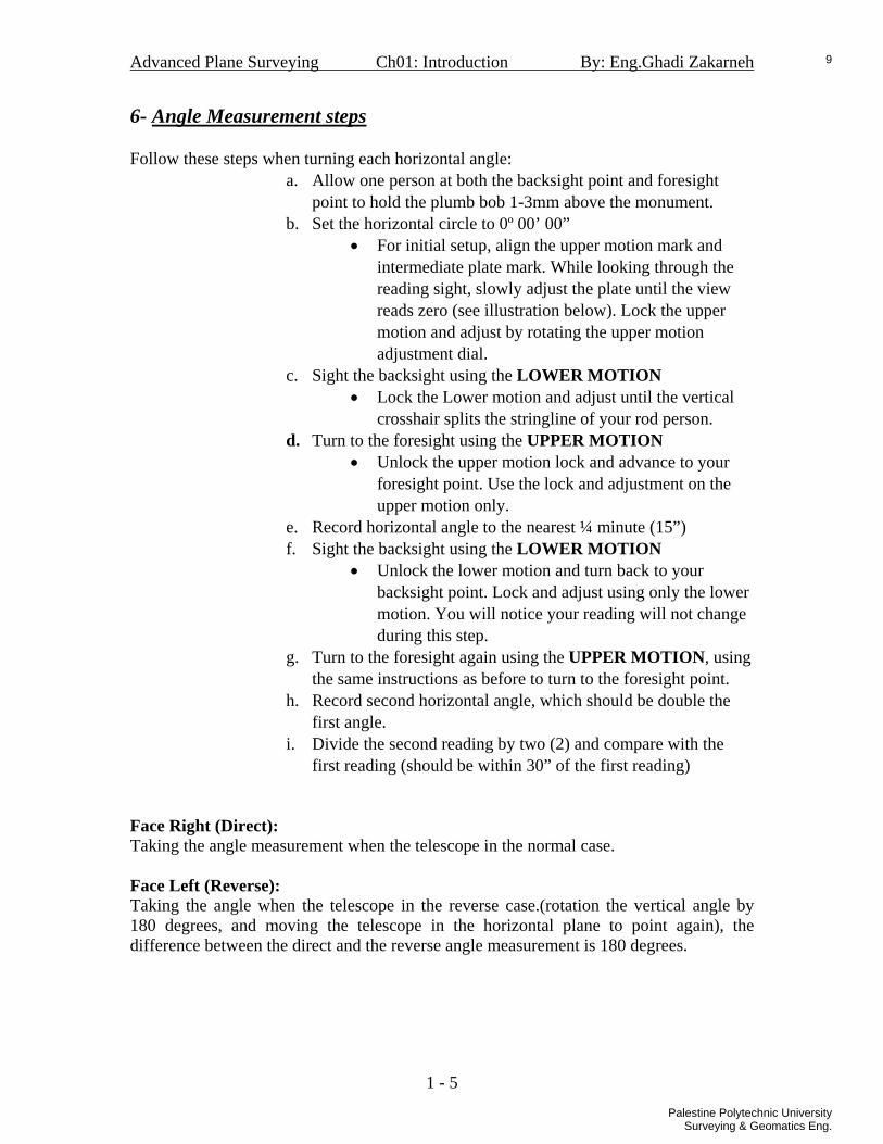
6- Angle Measurement steps Follow these steps when turning each horizontal angle:
a. Allow one person at both the backsight point and foresight point to hold the plumb bob 1-3mm above the monument.
b. Set the horizontal circle to 0º 00’ 00” • For initial setup, align the upper motion mark and
intermediate plate mark. While looking through the reading sight, slowly adjust the plate until the view reads zero (see illustration below). Lock the upper motion and adjust by rotating the upper motion adjustment dial.
c. Sight the backsight using the LOWER MOTION • Lock the Lower motion and adjust until the vertical
crosshair splits the stringline of your rod person. d. Turn to the foresight using the UPPER MOTION
• Unlock the upper motion lock and advance to your foresight point. Use the lock and adjustment on the upper motion only.
e. Record horizontal angle to the nearest ¼ minute (15”) f. Sight the backsight using the LOWER MOTION
• Unlock the lower motion and turn back to your backsight point. Lock and adjust using only the lower motion. You will notice your reading will not change during this step.
g. Turn to the foresight again using the UPPER MOTION, using the same instructions as before to turn to the foresight point.
h. Record second horizontal angle, which should be double the first angle.
i. Divide the second reading by two (2) and compare with the first reading (should be within 30” of the first reading)
Face Right (Direct): Taking the angle measurement when the telescope in the normal case. Face Left (Reverse): Taking the angle when the telescope in the reverse case.(rotation the vertical angle by 180 degrees, and moving the telescope in the horizontal plane to point again), the difference between the direct and the reverse angle measurement is 180 degrees.
1 - 5
9
Palestine Polytechnic UniversitySurveying & Geomatics Eng.

Advanced Plane Surveying Ch01: Introduction By: Eng.Ghadi Zakarneh
7- Angles by repetition
1. The steps from a-i are done for n-times. 2. After the last measurement (the telescope is still in the foresight), reverse the
telescope and turn it back to the foresight, the difference between the last measurement and the new measurement is nearly 180 degrees.
3. Turn to the backsight again using the UPPER MOTION. And register the angle measurements (it should be nearly 180 different from it,s corresponding direct measurement).
4. Turn to the foresight again using the LOWER MOTION. 5. Repeat 3 and 4 n-times. 6. Take the average of the differences of direct and reverse values of the angle.
Example: NOTE: we start direct up to down backsight to foresight. The reverse doun to up and foresight to backsight.
Direct Reverse Backsight foresight Difference Backsight foresight Difference00 00 00 45 12 30 4512 30 180 00 12 225 12 47 45 12 35 45 12 30 90 25 15 45 12 45 225 12 47 270 25 25 45 12 38 90 25 15 135 37 50 45 12 35 270 25 25 315 37 58 45 12 33 135 37 50 180 50 30 45 12 40 315 37 58 0 50 35(+360) 45 12 37
Average = 45 12 36.625 8- Zenith Angles in Direct and Reverse If the zenith angle is measured n-time direct and n-time reverse then:
Example:
1 - 6
10
Palestine Polytechnic UniversitySurveying & Geomatics Eng.

Advanced Plane Surveying Ch02: Traverses By: Eng.Ghadi Zakarneh
Ch02 Traverses
2 - 1
11
Palestine Polytechnic UniversitySurveying & Geomatics Eng.
Advanced Plane Surveying Ch02: Traverses By: Eng.Ghadi Zakarneh
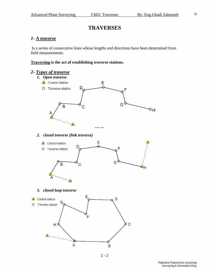
TRAVERSES 1- A traverse Is a series of consecutive lines whose lengths and directions have been determined from field measurements. Traversing is the act of establishing traverse stations. 2- Types of traverse
1. Open traverse
2. closed traverse (link traverse)
3. closed loop traverse
2 - 2
12
Palestine Polytechnic UniversitySurveying & Geomatics Eng.

Advanced Plane Surveying Ch02: Traverses By: Eng.Ghadi Zakarneh
2- Deflection Angle Traverse
2 - 3
13
Palestine Polytechnic UniversitySurveying & Geomatics Eng.

Advanced Plane Surveying Ch02: Traverses By: Eng.Ghadi Zakarneh
MN
LMVMN
RVUVM
RUTUV
LRTTU
RSRRT
AzgivenChechAzAzAzAzAzAzAzAzAzAz
5
4
3
2
1
ααααα
−=+=+=−=+=
2 - 4
14
Palestine Polytechnic UniversitySurveying & Geomatics Eng.

Advanced Plane Surveying Ch02: Traverses By: Eng.Ghadi Zakarneh
2 - 5
15
Palestine Polytechnic UniversitySurveying & Geomatics Eng.

Advanced Plane Surveying Ch02: Traverses By: Eng.Ghadi Zakarneh
3- Interior Angle Traverse
2 - 6
16
Palestine Polytechnic UniversitySurveying & Geomatics Eng.
Advanced Plane Surveying Ch02: Traverses By: Eng.Ghadi Zakarneh
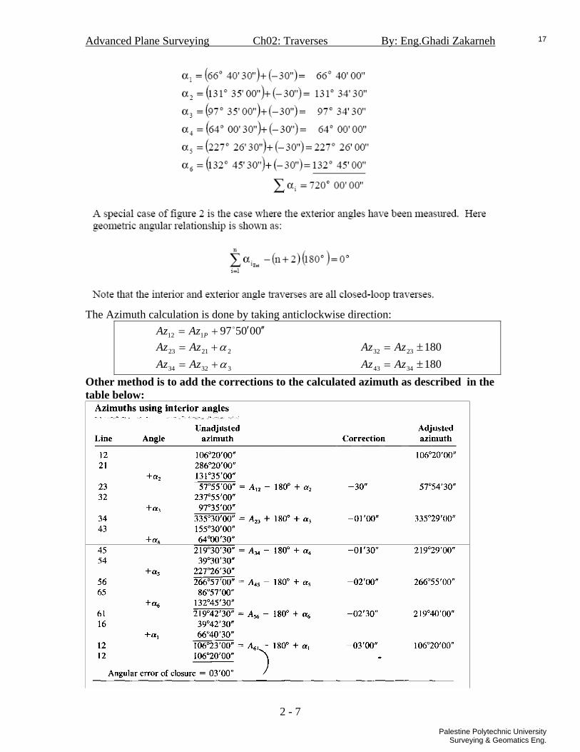
The Azimuth calculation is done by taking anticlockwise direction:
000597112 ′′′+= oPAzAz
22123 α+= AzAz 1802332 ±= AzAz
33234 α+= AzAz 1803443 ±= AzAz Other method is to add the corrections to the calculated azimuth as described in the table below:
2 - 7
17
Palestine Polytechnic UniversitySurveying & Geomatics Eng.

Advanced Plane Surveying Ch02: Traverses By: Eng.Ghadi Zakarneh
4- Angles to Right Traverse
2 - 8
18
Palestine Polytechnic UniversitySurveying & Geomatics Eng.
Advanced Plane Surveying Ch02: Traverses By: Eng.Ghadi Zakarneh
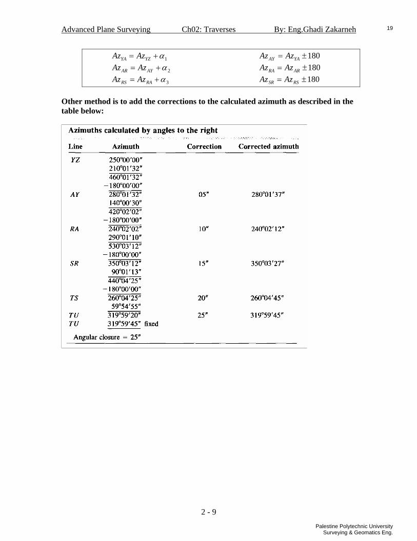
1α+= YZYA AzAz 180±= YAAY AzAz
2α+= AYAR AzAz 180±= ARRA AzAz
3α+= RARS AzAz 180±= RSSR AzAz
Other method is to add the corrections to the calculated azimuth as described in the table below:
2 - 9
19
Palestine Polytechnic UniversitySurveying & Geomatics Eng.

Advanced Plane Surveying Ch02: Traverses By: Eng.Ghadi Zakarneh
5- Traverse Computations
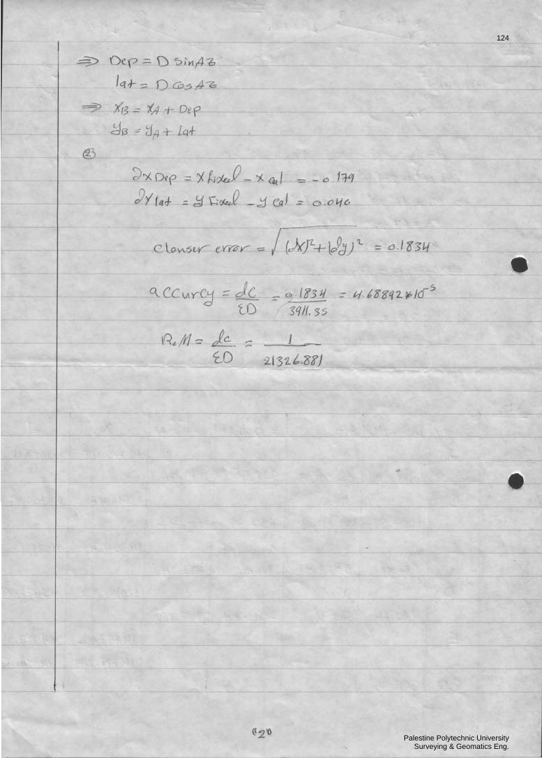
ijADXiDepXiXj sin.. +=+=
ijADXiLatYiYj cos.. +=+=
2 - 10
20
Palestine Polytechnic UniversitySurveying & Geomatics Eng.
Advanced Plane Surveying Ch02: Traverses By: Eng.Ghadi Zakarneh
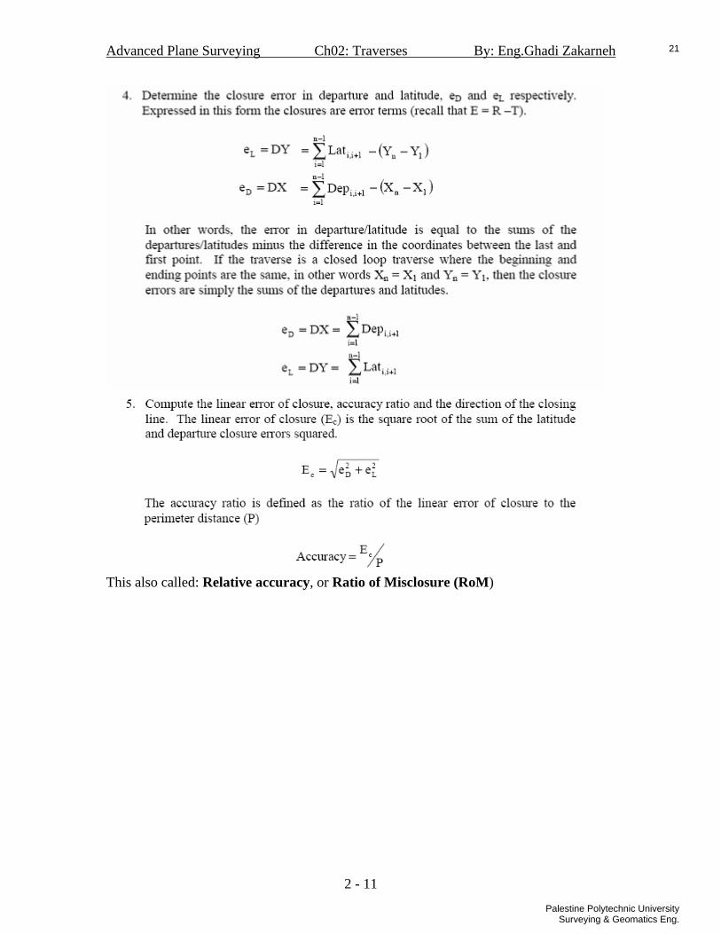
This also called: Relative accuracy, or Ratio of Misclosure (RoM)
2 - 11
21
Palestine Polytechnic UniversitySurveying & Geomatics Eng.

Advanced Plane Surveying Ch02: Traverses By: Eng.Ghadi Zakarneh
Example-1:
Solution:
21
5'1 ′′=−=cpa
Azimuth Calculations
2 - 12
22
Palestine Polytechnic UniversitySurveying & Geomatics Eng.

Advanced Plane Surveying Ch02: Traverses By: Eng.Ghadi Zakarneh
Relative accuracy= RoM = 0.36 / 1762.29 = 1 / 4894
2 - 13
23
Palestine Polytechnic UniversitySurveying & Geomatics Eng.

Advanced Plane Surveying Ch02: Traverses By: Eng.Ghadi Zakarneh
Example-2:
Relative accuracy= RoM = 0.28 / 1769.76 = 1 / 6320
2 - 14
24
Palestine Polytechnic UniversitySurveying & Geomatics Eng.

Advanced Plane Surveying Ch02: Traverses By: Eng.Ghadi Zakarneh
6 - Traverse Adjustment (Compass Rule) The errors in the traverse (linear misclosure) can be reduced according to compass rule:
• coordinates corrections
• latitude and Departure corrections
• Adjusted azimuth and distance Using the adjusted coordinates , the azimuth and the distance can be calculated again, these value are the adjusted values:
CYYXX
Aij
ijij +⎟
⎟⎠
⎞⎜⎜⎝
⎛
−
−= −1tan
Where ;
The adjusted distance:
( ) ( )22
ijijij YYXXd −+−=
2 - 15
25
Palestine Polytechnic UniversitySurveying & Geomatics Eng.

Advanced Plane Surveying Ch02: Traverses By: Eng.Ghadi Zakarneh
Example: For the last example,
2 - 16
26
Palestine Polytechnic UniversitySurveying & Geomatics Eng.

Advanced Plane Surveying Ch02: Traverses By: Eng.Ghadi Zakarneh
7- Traverse Accuracy standards
• Federal Geodetic Control Subcommittee (FGCS 1984)
• Palestine Land survey accuracy standards
2 - 17
27
Palestine Polytechnic UniversitySurveying & Geomatics Eng.
Advanced Plane Surveying Ch02: Traverses By: Eng.Ghadi Zakarneh
Problems
2 - 18
28
Palestine Polytechnic UniversitySurveying & Geomatics Eng.

Advanced Plane Surveying Ch02: Traverses By: Eng.Ghadi Zakarneh
2 - 19
29
Palestine Polytechnic UniversitySurveying & Geomatics Eng.

Advanced Plane Surveying Ch02: Traverses By: Eng.Ghadi Zakarneh
2 - 20
30
Palestine Polytechnic UniversitySurveying & Geomatics Eng.

Advanced Plane Surveying Ch02: Traverses By: Eng.Ghadi Zakarneh
2 - 21
31
Palestine Polytechnic UniversitySurveying & Geomatics Eng.

Advanced Plane Surveying Ch02: Traverses By: Eng.Ghadi Zakarneh
2 - 22
32
Palestine Polytechnic UniversitySurveying & Geomatics Eng.

Name: Traverse Adjustment Form Date: Page ____ of ____
Preliminary Corrections to Adjusted Coordinates Adjusted
Station Direction Distance Latitude Departure Latitude Departure Latitude Departure X Y Direction Distance
33
Palestine Polytechnic UniversitySurveying & Geomatics Eng.

Name: Traverse Adjustment Form Date: Page: ____ of _____ Readings Preliminary Preliminary Corrections Corrected Adjusted
St D Az Dep. Lat. Easting (X) Northing(Y) Xδ Yδ Easting Northing D Az
ΣD = dX= dY= Misclosure Error =
___________1RoM = Traverse Class=____________ □Accepted / □Rejected
34
Palestine Polytechnic UniversitySurveying & Geomatics Eng.

Advanced Plane Surveying Ch03: Intersections By: Eng.Ghadi Zakarneh
Ch03 Intersections
3 - 1
35
Palestine Polytechnic UniversitySurveying & Geomatics Eng.

Advanced Plane Surveying Ch03: Intersections By: Eng.Ghadi Zakarneh
INTERSECTIONS
A- Two angles Intersections
We measure the angles from a line between two known points to the new point. Then we can calculate the coordinates of the new points.
• To find point C : <A = <CAB clockwise <B = <ABC clockwise
• To find point C’ : <A = <BAC clockwise <B = <CAB clockwise
Calculation procedure:
1. Calculate the Azimuth of AB
CYYXXA
AB
ABAB +⎟⎟
⎠
⎞⎜⎜⎝
⎛−−
= −1tan Or CNNEEA
AB
ABAB +⎟⎟
⎠
⎞⎜⎜⎝
⎛−−
= −1tan
Where ;
3 - 2
36
Palestine Polytechnic UniversitySurveying & Geomatics Eng.

Advanced Plane Surveying Ch03: Intersections By: Eng.Ghadi Zakarneh
2. Calculate the length of AB
( ) ( )22ABAB YYXXAB −+−=
3. Calculate the angle <C=180-(<A + <B) 4. Calculate the Azimuth of AC and BC.
AAzAz ABAc <−= 180mABBA AzAz =
BAzAz BABc <+=
To find Azimuth AC’ and BC’ AAzAz ABAc <+='
180mABBA AzAz = BAzAz BABc <−=
5. Calculate the lengths of the lines AC and BC using sine Rule.
BC
ABAC sinsin
= and AC
ABBC sinsin
=
6. Calculate the coordinates of the C from A.
ACAAC AACXDepXX sin.. +=+=
ACAAC AACYLatYY cos.. +=+= Or ACAAC AACEDepEE sin.. +=+=
ACAAC AACNLatNN cos.. +=+=
7. Check by calculating the coordinates of the point C from B. BCBBC ABCXDepXX sin.. +=+=
BCBBC ABCYLatYY cos.. +=+= Or BCBBC ABCEDepEE sin.. +=+=
BCBBC ABCNLatNN cos.. +=+=
3 - 3
37
Palestine Polytechnic UniversitySurveying & Geomatics Eng.

Advanced Plane Surveying Ch03: Intersections By: Eng.Ghadi Zakarneh
Example: For the figure above find the coordinates of the point C. Calculate the Azimuth of AB
823583tan 1 ′′′=+⎟⎟⎠
⎞⎜⎜⎝
⎛−−
= − oCNNEEA
AB
ABAB
Calculate the length of AB
( ) ( ) mYYXXAB ABAB 12.33622 =−+−=
Calculate the angle <C=180-(<A+ <B) 814493 ′′′= oC
Calculate the Azimuth of AC and BC.
648250 ′′′=<−= oAAzAz ABAc 8235263180 ′′′== omABBA AzAz 8244316 ′′′=<+= oBAzAz BABc
Calculate the lengths of the lines AC and BC using sine Rule.
mBC
ABAC 48.268sinsin
==
mAC
ABBC 48.185sinsin
==
Calculate the coordinates of the C from A.
mAACEDepEE ACAAC 77.1751sin.. =+=+= mAACNLatNN ACAAC 03.1427cos.. =+=+=
Check by calculating the coordinates of the point C from B.
BCBBC ABCEDepEE sin.. +=+=
BCBBC ABCNLatNN cos.. +=+=
3 - 4
38
Palestine Polytechnic UniversitySurveying & Geomatics Eng.

Advanced Plane Surveying Ch03: Intersections By: Eng.Ghadi Zakarneh
B- Two Distance intersections
Two distances are measured from two known points to the new point.
Calculation procedure:
1. Calculate the Azimuth of AB
CYYXXA
AB
ABAB +⎟⎟
⎠
⎞⎜⎜⎝
⎛−−
= −1tan Or CNNEEA
AB
ABAB +⎟⎟
⎠
⎞⎜⎜⎝
⎛−−
= −1tan
Where ;
2. Calculate the length of AB
( ) ( )22ABAB YYXXAB −+−=
3. Calculate the angle A using Cosine Rule.
3 - 5
39
Palestine Polytechnic UniversitySurveying & Geomatics Eng.
Advanced Plane Surveying Ch03: Intersections By: Eng.Ghadi Zakarneh
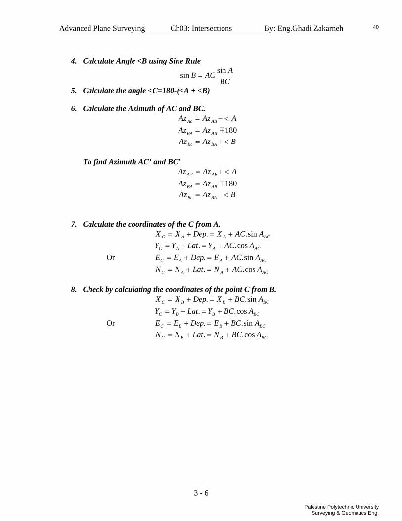
4. Calculate Angle <B using Sine Rule
BCAACB sinsin =
5. Calculate the angle <C=180-(<A + <B) 6. Calculate the Azimuth of AC and BC.
AAzAz ABAc <−= 180mABBA AzAz =
BAzAz BABc <+= To find Azimuth AC’ and BC’
AAzAz ABAc <+=' 180mABBA AzAz =
BAzAz BABc <−=
7. Calculate the coordinates of the C from A.
ACAAC AACXDepXX sin.. +=+=
ACAAC AACYLatYY cos.. +=+= Or ACAAC AACEDepEE sin.. +=+=
ACAAC AACNLatNN cos.. +=+=
8. Check by calculating the coordinates of the point C from B. BCBBC ABCXDepXX sin.. +=+=
BCBBC ABCYLatYY cos.. +=+= Or BCBBC ABCEDepEE sin.. +=+=
BCBBC ABCNLatNN cos.. +=+=
3 - 6
40
Palestine Polytechnic UniversitySurveying & Geomatics Eng.

Advanced Plane Surveying Ch03: Intersections By: Eng.Ghadi Zakarneh
Example: For the figure above find the coordinates of the point C.
Calculate the Azimuth of AB
640077tan 1 ′′′=+⎟⎟⎠
⎞⎜⎜⎝
⎛−−
= − oCNNEEA
AB
ABAB
Calculate the length of AB
( ) ( ) mYYXXAB ABAB 86.33522 =−+−=
Calculate the angle A using Cosine Rule.
108340 ′′′= oA
Calculate Angle <B using Sine Rule
254329sinsin ′′′== o
BCAACB
Calculate the Azimuth of AC and BC.
542236 ′′′=<−= oAAzAz ABAc 6400257180 ′′′=+= o
ABBA AzAz 8353286 ′′′=<+= oBAzAz BABc
Calculate the coordinates of the C from A.
mAACEDepEE ACAAC 95.729sin.. =+=+= mAACNLatNN ACAAC 01.1362cos.. =+=+=
Check by calculating the coordinates of the point C from B.
BCBBC ABCEDepEE sin.. +=+=
BCBBC ABCNLatNN cos.. +=+=
3 - 7
41
Palestine Polytechnic UniversitySurveying & Geomatics Eng.

Advanced Plane Surveying Ch03: Intersections By: Eng.Ghadi Zakarneh
C- finding the elevation of inaccessible point
To find the elevation of a point that can not be accessed like point P in the above figure, the following measurements are done:
• The vertical angles and or and 1v 2v 1z 2z• The horizontal angles A and B • The horizontal distance AB
Calculation procedure:
• Calculate the horizontal angle <P=180-(<A + <B) • Calculate the lengths of the Horizontal lines AP and BP using sine Rule.
BP
ABAP sinsin
= and AP
ABBP sinsin
=
• Calculate the Elevation of the P from A.
3 - 8
42
Palestine Polytechnic UniversitySurveying & Geomatics Eng.

Advanced Plane Surveying Ch03: Intersections By: Eng.Ghadi Zakarneh
)cot(...
)tan(...
1
1
zAPhiLRLR
vAPhiLRLR
AAP
AAP
A
A
++=
++=
• Calculate the Elevation of the P from B.
)cot(...
)tan(...
2
2
zBPhiLRLR
vBPhiLRLR
BBP
BBP
B
B
++=
++=
• The elevation of P is:
2..
. BA
B
PPP
LRLRLR
+=
Example: Stations A and B have elevations of 298.65 ft, and 301.53 ft, respectively, and the instrument heights at A and B are hiA = 5.55 ft, and hiB = 5.48 ft. The other field measurements are:
What is the elevation of the chimney stack P?
• Calculate the horizontal angle <P=180-(<A + <B) 030296 ′′′°= • Calculate the lengths of the Horizontal lines AP and BP using sine Rule.
ftBP
ABAP 233.87sinsin
==
ftAP
ABBP 730.95sinsin
==
• Calculate the Elevation of the P from A.
ftvAPhiLRLR AAPA791.316)tan(... 1 =++=
• Calculate the Elevation of the P from B.
ftvBPhiLRLR BBPB795.316)tan(... 2 =++=
• The elevation of P is:
ftLRLR
LR BA
B
PPP 793.316
2..
. =+
=
H.W : find the zenith angle and use it to find the elevation of P?
3 - 9
43
Palestine Polytechnic UniversitySurveying & Geomatics Eng.

Advanced Plane Surveying Ch03: Intersections By: Eng.Ghadi Zakarneh
Notes about Coordinates Systems In some countries the coordinates systems is define through using X as the easting coordinates , and Y as the northing coordinates. As we normally deal. Then:
ACAACC AACXDepXEX sin.. +=+==
ACAACC AACYLatYNY cos.. +=+==
CNNEEC
YYXXA
AB
AB
AB
ABAB +⎟⎟
⎠
⎞⎜⎜⎝
⎛−−
=+⎟⎟⎠
⎞⎜⎜⎝
⎛−−
= −− 11 tantan
this is used in the USA and other countries. In other countries the System is the opposite through using X as the northing coordinates, and Y as the easting coordinates. Then you can arrange your solution through:
• Interchange the names of the coordinates, use X as Y and Y as X. in the results interchange the names again.
• The other way is to calculate the coordinates and azimuths through:
ABAABB AABYDepYEY sin.. +=+==
ABAABB AABXLatXNX cos.. +=+==
CNNEEC
XXYYA
AB
AB
AB
ABAB +⎟⎟
⎠
⎞⎜⎜⎝
⎛−−
=+⎟⎟⎠
⎞⎜⎜⎝
⎛−−
= −− 11 tantan
This system is used in Palestine, Britain, Germany and other countries.
3 - 10
44
Palestine Polytechnic UniversitySurveying & Geomatics Eng.

Advanced Plane Surveying Ch03: Intersections By: Eng.Ghadi Zakarneh
D- Points Stake out (layout)by angles to right to fix points on the ground which are not identified, but they have known coordinates the following procedure id followed, to fix pint C on the ground using the EDM on point B and zero direction at point A, where points A and B have known coordinates and well identified on the ground, while the point C has to be identified on the ground:
1. calculate the length of the line BC
( ) ( )22CBCB NNEEBC −+−=
2. calculate the azimuth of the line BA
CNNEEAz
BA
BABA +⎟⎟
⎠
⎞⎜⎜⎝
⎛−−
= −1tan
3. calculate the azimuth of the line BC
CNNEE
AzBC
BCBC +⎟⎟
⎠
⎞⎜⎜⎝
⎛−−
= −1tan
4. calculate the clockwise angle ABC BABC AzAzABC −=<
If 0<< ABC then 360+<=< ABCABC 5. Set the EDM above the point B. 6. Set the instrument zero to A.
7. Read and angle with value of <ABC.
8. Fix the EDM direction.
9. Ask the reflector person to above nearer and further until the distance BC
is measured accurately in the fixed direction.
3 - 11
45
Palestine Polytechnic UniversitySurveying & Geomatics Eng.

Advanced Plane Surveying Ch03: Intersections By: Eng.Ghadi Zakarneh
Example: The given points below in graph are the centers of columns for a new building, the coordinates of the columns 60-72 are listed below. Prepare the calculations to mark the columns centers on the ground. The instrument is to be setup on the station 73 and the instrument (EDM) is to be zeroed at 74?
3 - 12
46
Palestine Polytechnic UniversitySurveying & Geomatics Eng.

Advanced Plane Surveying Ch03: Intersections By: Eng.Ghadi Zakarneh
3 - 13
47
Palestine Polytechnic UniversitySurveying & Geomatics Eng.

Advanced Plane Surveying Ch04: Resection By: Eng.Ghadi Zakarneh
Ch04 Resection
4 - 1
48
Palestine Polytechnic UniversitySurveying & Geomatics Eng.

Advanced Plane Surveying Ch04: Resection By: Eng.Ghadi Zakarneh
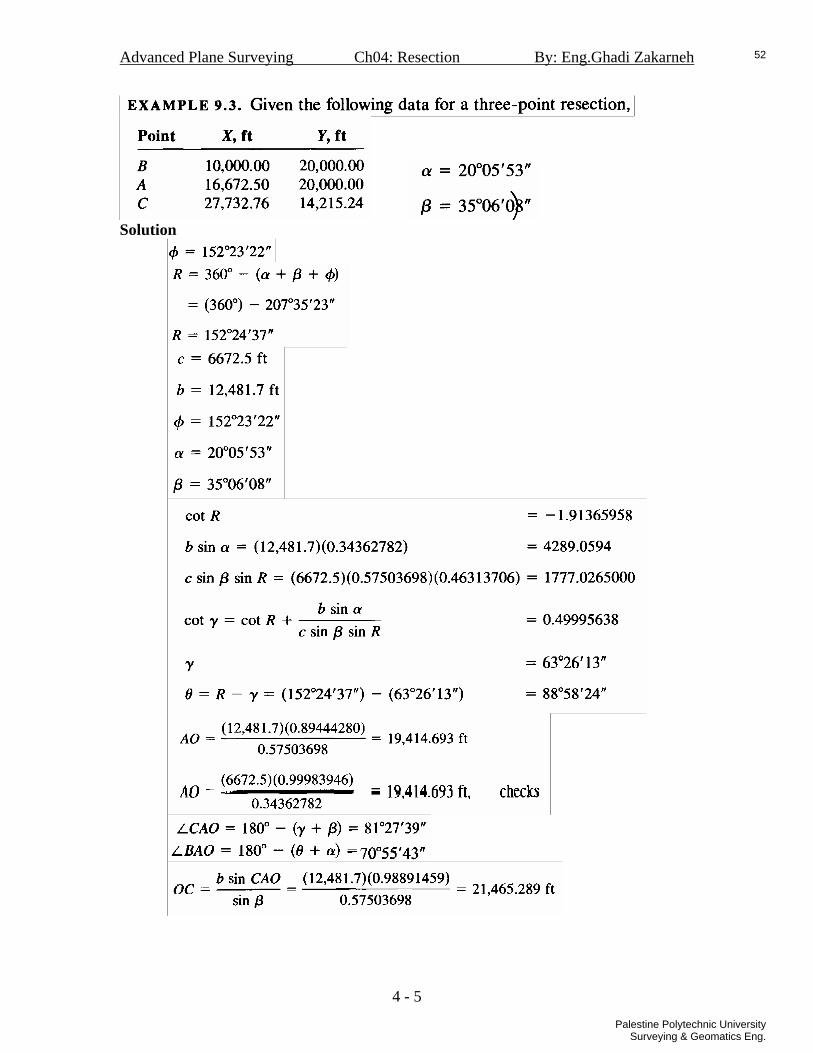
RESECTION
In this method, a theodelite is set up on a new point with unknown coordinates, and angles between three known points are measured to find the coordinates of the new point. 1- Derivation Using the figure below, O is the new point . A, B, and C are points with known coordinates. α and β are the observed angles. To solve the problem we need to calculate θ and γ .
We define R:
γθ +=R Using the Sine Rule in triangles OAC and OAB:
αθ
βγ
sinsin.
sinsin. cbAO ==
Arrange the above equation forθ :
βαγθ
sin.sin.sin.sin
cb
=
Because γθ −= R , using trigonometric functions for the sine of difference of two angles:
γγγθ sincoscos.sin)sin(sin RRR −=−=
βαγγγ
sin.sin.sin.sincoscos.sin
cbRR =−
Divide the above equations by γsin.sin R , then:
RcbR
sin.sin.sin.cotcotβαγ +=
γθ −= R
4 - 2
49
Palestine Polytechnic UniversitySurveying & Geomatics Eng.

Advanced Plane Surveying Ch04: Resection By: Eng.Ghadi Zakarneh
2- Problem cases
1. The problem has no solution if the clockwise angle 180=++< βαBAC because . ∞⇒Rcot
2. The problem has basically three cases. Depending on the figure below. • Cases (a,b):
( )βαφγθ ++−=+= 360R
• Case ( c) : βαφγθ −−=+=R
4 - 3
50
Palestine Polytechnic UniversitySurveying & Geomatics Eng.

Advanced Plane Surveying Ch04: Resection By: Eng.Ghadi Zakarneh
3- Calculation procedure
1. Determine the case of your solution, if: • bcase⇒>+ 180βα • acaseAzAzBAC AcAB ⇒<−=< 180 • ccaseAzAzBAC AcAB ⇒>−=< 180
2. Using the coordinates of points A,B and C ,calculate the distances : a,b, and c. 3. calculates the angle φ :
• case a : AcAB AzAzBAC −==<φ • case b: ABAC AzAz −=φ • case c: ABAC AzAz −=φ
4. compute R: • cases (a,b): ( )βαφ ++−= 360R • case ( c): βαφ −−=R
5. calculate γ :
RcbR
sin.sin.sin.cotcotβαγ +=
6. calculate θ γθ −= R
7. calculate AO:
αθ
βγ
sinsin.
sinsin. cbAO ==
8. compute <CAO and <BAO: ( )βγ +−=< 180CAO
)(180 αθ +−=< BAO 9. Calculate the line OC and OB, using sine Rule:
βsin)sin(. CAObOC <
=
αsin)sin(. BAOcOB <
=
10. calculate azimuth of CO and BO: • cases a,c: γ−= CACO AzAz θ+= BABO AzAz • case b: γ+= CACO AzAz θ−= BABO AzAz
11. calculate the coordinates of O: COCCO AOCXDepXX sin.. +=+=
COCCO AOCYLatYY cos.. +=+= 12. Check,
BOBBO AOBXDepXX sin.. +=+=
BOBBO AOBYLatYY cos.. +=+=
4 - 4
51
Palestine Polytechnic UniversitySurveying & Geomatics Eng.
Advanced Plane Surveying Ch04: Resection By: Eng.Ghadi Zakarneh
Solution
4 - 5
52
Palestine Polytechnic UniversitySurveying & Geomatics Eng.
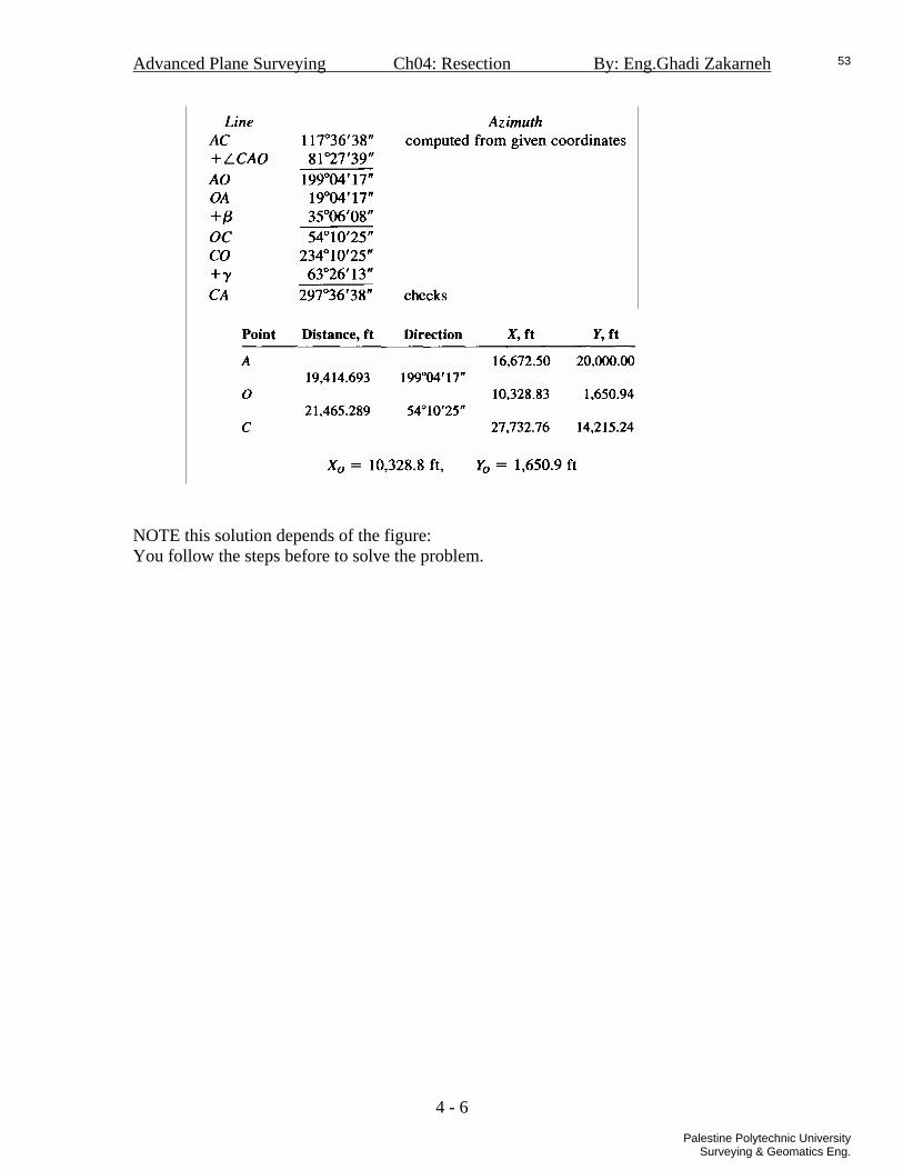
Advanced Plane Surveying Ch04: Resection By: Eng.Ghadi Zakarneh
NOTE this solution depends of the figure: You follow the steps before to solve the problem.
4 - 6
53
Palestine Polytechnic UniversitySurveying & Geomatics Eng.

Advanced Plane Surveying Ch04: Resection By: Eng.Ghadi Zakarneh
Problems:
4 - 7
54
Palestine Polytechnic UniversitySurveying & Geomatics Eng.

Advanced Plane Surveying Ch04: Resection By: Eng.Ghadi Zakarneh
4 - 8
55
Palestine Polytechnic UniversitySurveying & Geomatics Eng.

Advanced Plane Surveying Ch05: Traverse Missed Data By: Eng.Ghadi Zakarneh
Ch05 Traverse
Missed data
5 - 1
56
Palestine Polytechnic UniversitySurveying & Geomatics Eng.

Advanced Plane Surveying Ch05: Traverse Missed Data By: Eng.Ghadi Zakarneh
TRAVERSE MISSED DATA When some measurements are missed in a traverse, you nee to complete these data, it is not always necessary to do field measurement again. Here are some examples that show how to find the values of the missed data: 1- Two Distances are missed Depending ing the figure below, for a closed polygon we can solve the problem as below:
In a traverse, we start at a known point (X,Y) and we end at other known point, then: firstlast XXAzDDep −==∑ ∑ sin.
∑ ∑ −== firstlast YYAzDLat cos.
NOTE: in close loop traverse the first point is also the last point. Then we have for the points with known distance and azimuths :
( ) ( ) ( )( ) ( ) ( )∑ ∑
∑ ∑Δ=−−=−−
Δ=−−=−−
YYYAzDYYLat
XXXAzDXXDep
firstlastfirstlast
firstlastfirstlast
cos.
sin. .1
For a closed loop traverse:
∑ ∑∑ ∑
Δ==
Δ==
YAzDLat
XAzDDep
cos.
sin. .1a
Then if the unknown distance are D1 and D2, we have :
5 - 2
57
Palestine Polytechnic UniversitySurveying & Geomatics Eng.

Advanced Plane Surveying Ch05: Traverse Missed Data By: Eng.Ghadi Zakarneh
.a .b
By eq.a we get:
.2
.3a
Or .3b Example: For the following closed loop traverse find the missed data
Using eq.1a:
Using eq.3:
Using eq.2
5 - 3
58
Palestine Polytechnic UniversitySurveying & Geomatics Eng.

Advanced Plane Surveying Ch05: Traverse Missed Data By: Eng.Ghadi Zakarneh
2- A Distance of a line and a direction of other line are missed Suppose the following:
• the unknowns are and , 1Az 2D• and 2sin AzM = 2cos AzN = .
Using eq.1 or eq.1a:
( ) ( ) ( )( ) ( ) ( )∑ ∑
∑ ∑Δ=−−=−−
Δ=−−=−−
YYYAzDYYLat
XXXAzDXXDep
firstlastfirstlast
firstlastfirstlast
cos.
sin. .1
∑ ∑∑ ∑
Δ==
Δ==
YAzDLat
XAzDDep
cos.
sin. .1a
We have: Arrange the above equations for and : 1sin Az 1cos Az
.4a
.4b Squaring the above equations:
.c
.d The summation of eq.c and eq.d:
But , then: 1cossin 22 =+ αα
.e
5 - 4
59
Palestine Polytechnic UniversitySurveying & Geomatics Eng.

Advanced Plane Surveying Ch05: Traverse Missed Data By: Eng.Ghadi Zakarneh
In the above equation we have 2nd order equation with unknown : 2D
a
acbbD2
42
2−±−
=
But , then a=1, and : 1cossin 22 =+ αα
242
2cbbD −±−
= .5a
Or
.5b
The value of , we calculate the sine and cosine of the azimuth using eq.4a and eq.4b: 1Az
.4a
.4b To find the quarters by finding or using the following graph: Aztan
cAzAzAz +⎟⎟
⎠
⎞⎜⎜⎝
⎛= −
1
111 cos
sintan .6
**** Keep the algebraic signs of when you add the value of c.1tan −
5 - 5
60
Palestine Polytechnic UniversitySurveying & Geomatics Eng.

Advanced Plane Surveying Ch05: Traverse Missed Data By: Eng.Ghadi Zakarneh
Example: For the following closed loop traverse find the missed data
Using eq.1:
Using eq.5b:
Using eq.4a and eq.4b:
=-0.6723955146
=-0.7401920491 The sine and the cosine are negatives; this means the line is in the 3rd quarter. Then using eq.6 we get:
8051222180805142180cossintan
1
111 ′′′=+′′′=+⎟⎟
⎠
⎞⎜⎜⎝
⎛= − oo
AzAzAz
5 - 6
61
Palestine Polytechnic UniversitySurveying & Geomatics Eng.
Advanced Plane Surveying Ch05: Traverse Missed Data By: Eng.Ghadi Zakarneh
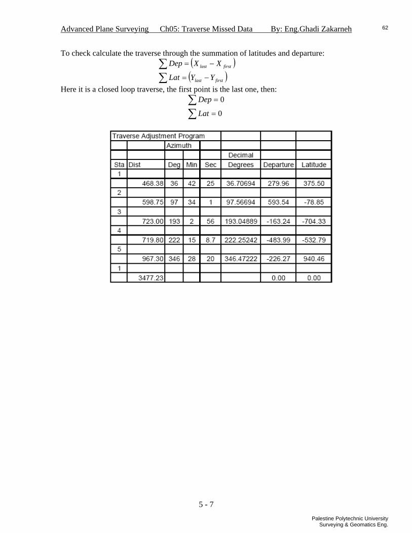
To check calculate the traverse through the summation of latitudes and departure: ( )( )∑
∑−=
−=
firstlast
firstlast
YYLat
XXDep
Here it is a closed loop traverse, the first point is the last one, then:
∑∑
=
=
0
0
Lat
Dep
5 - 7
62
Palestine Polytechnic UniversitySurveying & Geomatics Eng.

Advanced Plane Surveying Ch05: Traverse Missed Data By: Eng.Ghadi Zakarneh
3- Two azimuths are unknown Suppose the following:
• the unknowns are and , 1Az 2Az• and 2sin AzM = 2cos AzN = .
Using eq.1 or eq.1a:
( ) ( ) ( )( ) ( ) ( )∑ ∑
∑ ∑Δ=−−=−−
Δ=−−=−−
YYYAzDYYLat
XXXAzDXXDep
firstlastfirstlast
firstlastfirstlast
cos.
sin. .1
∑ ∑∑ ∑
Δ==
Δ==
YAzDLat
XAzDDep
cos.
sin. .1a
We have:
.f
.g
Squaring the above two equations:
By The sum of the two equations, and , we: 1cossin 22 =+ αα
Rearranging:
Divide by :
If : Then:
5 - 8
63
Palestine Polytechnic UniversitySurveying & Geomatics Eng.

Advanced Plane Surveying Ch05: Traverse Missed Data By: Eng.Ghadi Zakarneh
But: We get:
But:
Then ,
.7 Using eq.f , eq.g , and and 2sin AzM = 2cos AzN = :
cAzAzAz +⎟⎟
⎠
⎞⎜⎜⎝
⎛= −
1
111 cos
sintan .8
****NOTE: for this solution the quarter of the must be known. Unless the solution can not be correct.
2Az
Example: If the 4th line is in the 3rd quarter, what are value of the missed data :
h.w ? use eq.1 use eq.7 use eq.8
5 - 9
64
Palestine Polytechnic UniversitySurveying & Geomatics Eng.

Advanced Plane Surveying Ch05: Traverse Missed Data By: Eng.Ghadi Zakarneh
Problems
5 - 10
65
Palestine Polytechnic UniversitySurveying & Geomatics Eng.

Advanced Plane Surveying Ch06: Horiz. Circular Curves By: Eng.Ghadi Zakarneh
Ch06 Horizontal
Circular Curves
6 -1
66
Palestine Polytechnic UniversitySurveying & Geomatics Eng.

Advanced Plane Surveying Ch06: Horiz. Circular Curves By: Eng.Ghadi Zakarneh
HORIZANTAL CIRCULAR CURVES
Many features, like roads, consist of a series of straight-line segments brought together by horizontal and vertical curves. A horizontal curve is an arc placed between two lines called tangents. Types of horizontal Curves:
• Simple Curve. • Compound Curve. • Broken-Back Curve. • Reverse Curve.
Other type of horizontal curves is used; it is called the transition or spiral curves. These curves are used to move from straight line to a circular curve and to apply the superelevation. The figure below shows the methods of applying transition curves.
6 -2
67
Palestine Polytechnic UniversitySurveying & Geomatics Eng.

Advanced Plane Surveying Ch06: Horiz. Circular Curves By: Eng.Ghadi Zakarneh
1- Degree of the Curve (D) An important relationship is the association between the degree of curve and the radius. The degree of curve is the angle at the center of the circle that lays out 100’. The radius is the distance from the center of the circle to the curve itself. There are two methods of defining this relationship:
• Arc method; most common approach. • Chord method.
• Arc Method
ft .1a
In metric units :
DR 1746= meter .1b
• Chord Method
( )2sin'50
DR = ft 1.c
)2sin(
24.15D
R = meter 1.d
6 -3
68
Palestine Polytechnic UniversitySurveying & Geomatics Eng.

Advanced Plane Surveying Ch06: Horiz. Circular Curves By: Eng.Ghadi Zakarneh
2- Elements of the Circular curve
The elements of the horizontal circular curve are shown in the figure below:
6 -4
69
Palestine Polytechnic UniversitySurveying & Geomatics Eng.

Advanced Plane Surveying Ch06: Horiz. Circular Curves By: Eng.Ghadi Zakarneh Tangent distance:
2. The long chord:
.3 The middle ordinate:
.4
The external distance:
.5 the length of curve: in radians .6a
in degrees .6b
6 -5
70
Palestine Polytechnic UniversitySurveying & Geomatics Eng.

Advanced Plane Surveying Ch06: Horiz. Circular Curves By: Eng.Ghadi Zakarneh EXAMPLE: Calculate the elements of the horizontal curve, while D=3º40`00``, ∆=24º20`00``, ST. (PI) =5+062.48. Solution:
28.47637.1746==
DR
T= R*tan )2
(Δ =102.685 m.
Lc=2R*sin )2
(Δ =200.75 m.
M=R-R*cos )2
(Δ =10.97 m.
E= .943.10)
2cos(
mRR=−
Δ
L= .17.202180
mR=
ΔΟ
π
ST. (PC) =ST (PI) – T= 4+959.795 m. ST (PT) =ST (PC) +L= 5+ 161.965 m.
6 -6
71
Palestine Polytechnic UniversitySurveying & Geomatics Eng.

Advanced Plane Surveying Ch06: Horiz. Circular Curves By: Eng.Ghadi Zakarneh
3- Circular curve setting out (layout) 3.1- small chords and deflection angles (using thedelite and tape )
The principle is that the angle from the PC where the theodelite is setup to a point on a circular curve (δ) is one-half of the central angle (d) subtended.
d1/21 =δ .7
π
π 180180
.RsddRs =⇒= .8
( )2sin..2 dRc = .9
Using the above principle the circular curve is divided to sub chords ( c ) , these chords are normally smaller than R/20 t, this make the chords nearly equal to arcs.
scRc ≈⇒≤20
6 -7
72
Palestine Polytechnic UniversitySurveying & Geomatics Eng.

Advanced Plane Surveying Ch06: Horiz. Circular Curves By: Eng.Ghadi Zakarneh
• The first selection of the arc ( s1 ) is done to make the station to be rounded to regular number. Then the deflection angle is:
π18011
Rsd =
And the the chord length ( c1 ) is : ( )2
1sin..21 dRc =
• the internal arcs ( s ) are selected to have rounded number of stations, then the deflection angle is:
π180
Rsd =
And the the chord length ( c1 ) is : ( )2sin..2 dRc =
• for the last arc the length is fixed to make ( s1 + n.s + s2 =L ), then the deflection
angle is:
π18022
Rsd =
And the the chord length ( c1 ) is : ( )2
2sin..22 dRc =
• The deflection angles to points on the circular curve are cumulative as follows:
6 -8
73
Palestine Polytechnic UniversitySurveying & Geomatics Eng.

Advanced Plane Surveying Ch06: Horiz. Circular Curves By: Eng.Ghadi Zakarneh
M
M
)2/(52/12/2/2/2/2/14)2/(32/12/2/2/2/14
)2/(22/12/2/2/132/2/12
2/11
ddddddddddddd
ddddddd
d
+=++++=+=+++=
+=++=+=
=
δδδδδ
6 -9
74
Palestine Polytechnic UniversitySurveying & Geomatics Eng.

Advanced Plane Surveying Ch06: Horiz. Circular Curves By: Eng.Ghadi Zakarneh EXAMPLE:- Find the chords and deflections by the way of (deflection with small chords) while R=476.28 m, L=202.17 m, ∆=24º20`00``, ST (PC) = 4+959.97 m, ST (PT) = 5+161.965 m , use S=20 m ? Solution:-
ST (1) = 4+980 m. S1=ST (1) – ST (PC) = 20.21 m.
44.5621121144.5252218011 ′′′°==⇒′′′°==
dRsd δ
π
( ) mmdRc 21.20209.2021sin..21 ≈==
S=20
57.102112
94.21422180 ′′′°==⇒′′′°==d
Rsd δ
π
( ) mmdRc 20999.192sin..2 ≈==
S2=21.96
61.1591122223.3083218022 ′′′°==⇒′′′°==
dRsd δ
π
( ) mmdRc 96.21958.2122sin..22 ≈==
Station S C d/2 δ (PC) =
4+959.97 0 0 0 0
4+980 20.21 20.209 44.56211 ′′′° 44.56211 ′′′° 5+000 20 20 57.10211 ′′′° 91.7522 ′′′° 5+020 20 20 57.10211 ′′′° 49.17733 ′′′° 5+040 20 20 57.10211 ′′′° 96.28944 ′′′° 5+060 20 20 57.10211 ′′′° 44.39106 ′′′° 5+080 20 20 57.10211 ′′′° 91.50317 ′′′° 5+100 20 20 57.10211 ′′′° 49.0628 ′′′° 5+120 20 20 57.10211 ′′′° 96.11839 ′′′° 5+140 20 20 57.10211 ′′′° 44.220510 ′′′°
5+161.96 21.96 21.96 61.15911 ′′′° 6.37912 ′′′° 2/6.37912 Δ≈′′′°=∑
6 -10
75
Palestine Polytechnic UniversitySurveying & Geomatics Eng.

Advanced Plane Surveying Ch06: Horiz. Circular Curves By: Eng.Ghadi Zakarneh
3.2- long chords and deflection angles(using Total Stations) the idea is the same basic idea as in the previous method the following relations are used, the total station is setup on point PC , and distance are measured from PC to the point on the curve. As shown in the figure below.
The basic relations are as describe below:
• The arc ( S ) is the distance from PC to the point on the curve.
• The deflection angle from the tangent is :
π180iδ
21
2 RSdi
i ==
RCi sin..2
• The chord that represents the distance which has to be read with the Total station is:
( ) mmi 21.20209.20 ≈=δ =
6 -11
76
Palestine Polytechnic UniversitySurveying & Geomatics Eng.

Advanced Plane Surveying Ch06: Horiz. Circular Curves By: Eng.Ghadi Zakarneh Example :- Prepare the calculation for Setting out the curve with (deflection angle and long chord) , where L=202.17 m, R =476.28 m, ∆=24º20`, T=102.68 m.
Station S C δ
(pc) 4+959.79 0 0 0 4+980 20.21 20.22 1º12`58.48`` 5+000 40.21 40.21 2º25`11.4`` 5+020 60.21 60.21 3º37`24.46`` 5+040 80.21 80.15 4º49`37.40`` 5+060 100.21 100.07 6º1`50.43`` 5+080 120.21 119.952 7º14`00`` 5+100 140.21 139.78 8º26`16.14`` 5+120 160.21 159.537 9º38`29.39`` 5+140 180.21 179.228 10º50`42.35``
5+161.965 202.175 200.765 12º10`1.08``
6 -12
77
Palestine Polytechnic UniversitySurveying & Geomatics Eng.

Advanced Plane Surveying Ch06: Horiz. Circular Curves By: Eng.Ghadi Zakarneh
3.3- Setting out the curve using offset from the tangent (x, y) coordinate from the tangent
Using the calculation of the above method the xy-coordinates are calculated for a point are calculated:
δcos.ii Cx = δsin.ii Cy =
Example: Prepare the calculation for Setting out the curve with (deflection angle and long chord) , where L=202.17 m, R =476.28 m, ∆=24º20`, T=102.68 m.
Station S C δ x y
(pc) 4+959.79
0 0 0 0 0
4+980 20.21 20.22 1º12`58.48`` 20.21 0.429 5+000 40.21 40.21 2º25`11.4`` 40.17 1.698 5+020 60.21 60.21 3º37`24.46`` 60.08 3.804 5+040 80.21 80.15 4º49`37.40`` 79.86 6.744 5+060 100.21 100.07 6º1`50.43`` 99.52 10.5135+080 120.21 119.952 7º14`00`` 118.997 5+100 140.21 139.78 8º26`16.14`` 5+120 160.21 159.537 9º38`29.39`` 5+140 180.21 179.228 10º50`42.35``
5+161.965 202.175 200.765 12º10`1.08`` 6 -13
78
Palestine Polytechnic UniversitySurveying & Geomatics Eng.

Advanced Plane Surveying Ch06: Horiz. Circular Curves By: Eng.Ghadi Zakarneh
3.4- setting out the horizontal curve by offset from the long chord
Using the calculation of the of the deflections and chords in section 3.4 the xy-coordinates shown in the figure below are calculated for a point as follows:
δθ −Δ= 2
θcos.ii Cx = θsin.ii Cy =
3.5- setting out the curve by radial distances from the tangent to the curve centre
Using the calculation of the deflections and chords in section 3.4 the xy-coordinates shown in the figure below are calculated for a point as follows:
⎟⎠⎞
⎜⎝⎛=⇒= −
Rx
ddRx ii
1tan)tan(.
RxRyi −+= 22
6 -14
79
Palestine Polytechnic UniversitySurveying & Geomatics Eng.

Advanced Plane Surveying Ch06: Horiz. Circular Curves By: Eng.Ghadi Zakarneh Problems 6.1 For a highway a curve is to be designed with degree=2°, and deflection angle is 75°,
the station of the of PI= 2+500, calculate the curve elements using chord definition, and use small chords method to prepare setting out table?
6.2 For a highway a curve is to be designed with degree=3°, and deflection angle is 75°,
the station of the of PI= 2+500, calculate the curve elements using arc chord definition, and use small chords method to prepare setting out table?
6.3 For problem 6.2, using long chords method to prepare setting out table? 6.4 For problem 6.2, using offsets from tangent method to prepare setting out table? 6.5 For problem 6.2, using offsets from the long chord method to prepare setting out
table? 6.6 For problem 6.2 , using radial distances from the tangent to the curve centre method
to prepare setting out table?
6 -15
80
Palestine Polytechnic UniversitySurveying & Geomatics Eng.

Advanced Plane Surveying Ch07: Coord. Transformations By: Eng.Ghadi Zakarneh
Ch07 Coordinates
Transformations
7 -1
81
Palestine Polytechnic UniversitySurveying & Geomatics Eng.

Advanced Plane Surveying Ch07: Coord. Transformations By: Eng.Ghadi Zakarneh
COORDINATES TRANSFORMATIONS
When dealing with map, we have maps with different scales, orientations and coordinates origins. Then coordinates are used to move the coordinates from one map system to the other. 1- 2D conformal coordinates transformations In this type of coordinate’s transformations as shown in the figure below, we have three steps; scale change, rotation and two translations:
Step 1: Scale Change
• The lengths of lines ab and AB are unequal; hence the scales of the two coordinate systems are unequal.
• The scale of the XY system is made equal to that of the EN system by multiplying each X and Y coordinate by a scale factor s. The scaled coordinates are designated as X’ and Y’.
• By use of the two control points, the scale factor is calculated in relation to the two lengths AB and ab as:
Step 2: Rotation
• If the scaled X’Y’ coordinate system is superimposed over the EN system , so that line AB in both systems coincide, the result is as shown in Figure below.
• An auxiliary axis system E’N’ is constructed through the origin of the X’Y’ axis system parallel to the EN axes.
• It is necessary to rotate from the X’ Y’ system to the E’N’ system, or in other words, to calculate E’N’ coordinates for the unknown points from their X’ Y’ coordinates.
7 -2
82
Palestine Polytechnic UniversitySurveying & Geomatics Eng.

Advanced Plane Surveying Ch07: Coord. Transformations By: Eng.Ghadi Zakarneh
• The E’N’ coordinates of point C may be calculated in terms of the clockwise angle θ by using the following equations:
Where,
βαθ +=
Or more general : ABab AzAz +=θ
Step 3: Translation • The final step in the coordinate transformation is a translation of the origin of the
E’N’ system to the origin of the EN system. • The translation factors required are and , which are illustrated in the above
figure. Final E and N ground coordinates for points C then are: ET NT
7 -3
83
Palestine Polytechnic UniversitySurveying & Geomatics Eng.

Advanced Plane Surveying Ch07: Coord. Transformations By: Eng.Ghadi Zakarneh
7 -4
84
Palestine Polytechnic UniversitySurveying & Geomatics Eng.

Advanced Plane Surveying Ch07: Coord. Transformations By: Eng.Ghadi Zakarneh
7 -5
85
Palestine Polytechnic UniversitySurveying & Geomatics Eng.
Advanced Plane Surveying Ch07: Coord. Transformations By: Eng.Ghadi Zakarneh
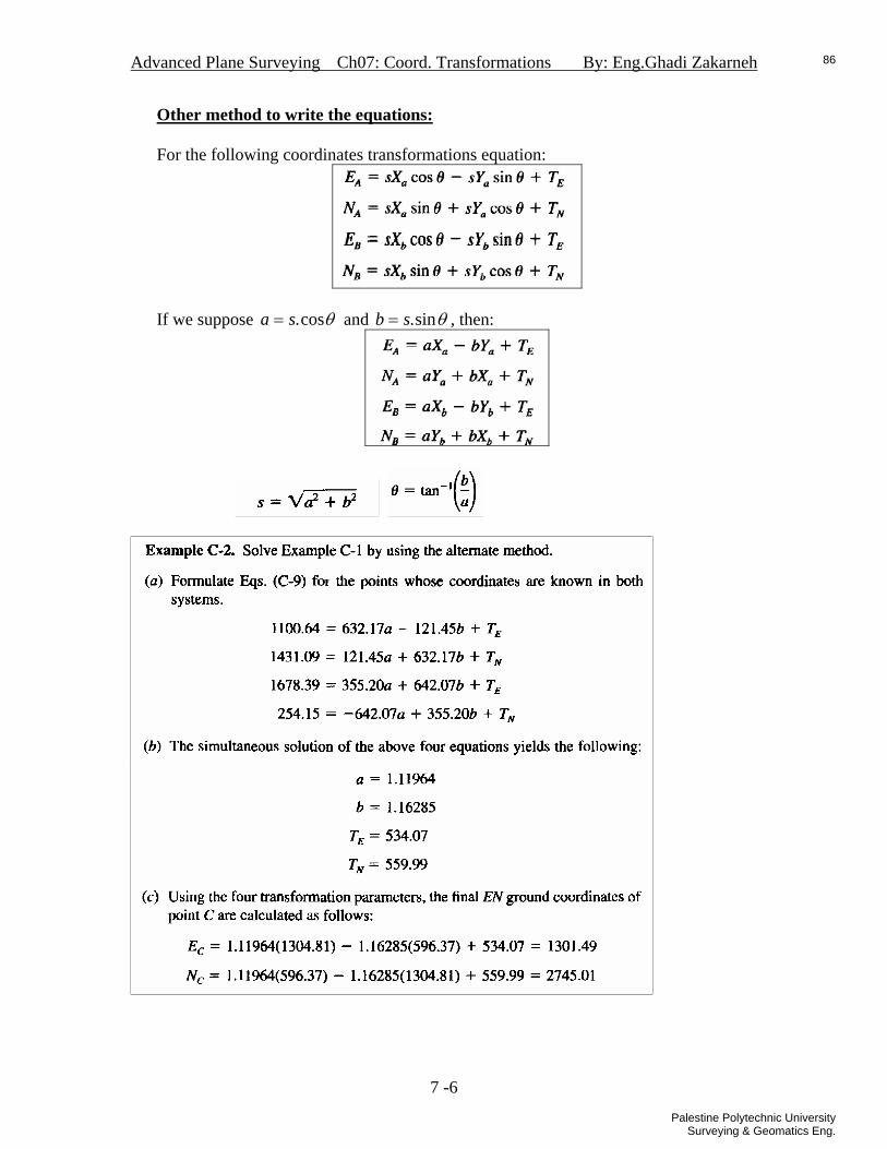
Other method to write the equations: For the following coordinates transformations equation:
If we suppose θcos.sa = and θsin.sb = , then:
7 -6
86
Palestine Polytechnic UniversitySurveying & Geomatics Eng.

Advanced Plane Surveying Ch07: Coord. Transformations By: Eng.Ghadi Zakarneh
Matrix Solution to find the parameters of coordinates transformations Suppose we have two points A and B, known in the source coordinates system XY and in the target coordinates system EN. We use these points to find the parameters of the coordinate’s transformation.
The matrix solution for any group of equations is:
LAX = Where,
A: is the design matrix, where each equation gives a row and each unknown gives a column. The elements of A are the factors multiplied by the unknowns in the equation. Each point gives two equations in E-direction and N-direction. So if we have n-points then the size of A is 2nX4. In the above group of equations:
4210011001
×
⎥⎥⎥⎥
⎦
⎤
⎢⎢⎢⎢
⎣
⎡
−
−
=
nB
B
A
A
NE
XbYbYbXb
XaYaYaXa
NENE
TTba
A
X: the vector of unknowns the size is fixed: 14× .
14×
⎥⎥⎥⎥
⎦
⎤
⎢⎢⎢⎢
⎣
⎡
=
N
E
TTba
X
L: the vector of observations, it contains the observed EN-coordinates of the known points. If we have n-points the size of L is 12 ×n .
12 ×
⎥⎥⎥⎥
⎦
⎤
⎢⎢⎢⎢
⎣
⎡
=
nB
B
A
A
NENE
L
The solution to find the unknown is as follows: ( ) LAAAX TT 1−
= For the previous example the calculated parameters can be used to calculate the EN-coordinates of the new point C.
***NOTE: to solve the matrix solution software is needed to multiply and inverse the matrices. e.g. EXCEL, MATLAB, Maple, MathCAD… etc.
7 -7
87
Palestine Polytechnic UniversitySurveying & Geomatics Eng.

Advanced Plane Surveying Ch07: Coord. Transformations By: Eng.Ghadi Zakarneh
2- Affine coordinates Transformations In the affine coordinates transformations, to transform from xy-coordinates to XY-coordinates. As shown in the figure below, we have:
• Different scales in the x direction and y-direction. • Rotation angle. • The x-axis and y-axis are not orthogonal. • Two translations in the x and y directions.
Step 1: scaling in the x and y direction If we scale the xy-coordinates we get new coordinates system y’y’-coordinates:
Step 2: non-orthogonality correction
this step we find new coordinates system x”y”. so that x”-axis and y”-axis are orthogonal. In the figure below, ε is the non-orthogonality angle.
7 -8
88
Palestine Polytechnic UniversitySurveying & Geomatics Eng.

Advanced Plane Surveying Ch07: Coord. Transformations By: Eng.Ghadi Zakarneh
Step 3: Rotation In this step we rotate the x”y”-coordinates X’Y’-coordinates, where X’Y’-coordinate are parallel to XY-coordinates. θ is the rotation angle between the y”-axis and the Y’-axis:
Step 4: Translation
In this step we add shift values to X’Y’-coordinates to get XY required coordinates:
Using the values of X’Y’, we get
This can be arranged as follows:
7 -9
89
Palestine Polytechnic UniversitySurveying & Geomatics Eng.
Advanced Plane Surveying Ch07: Coord. Transformations By: Eng.Ghadi Zakarneh
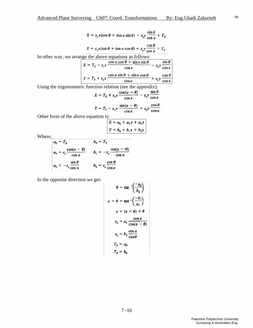
In other way, we arrange the above equations as follows:
Using the trigonometric function relation (see the appendix):
Other form of the above equation is:
Where,
In the opposite direction we get:
7 -10
90
Palestine Polytechnic UniversitySurveying & Geomatics Eng.

Advanced Plane Surveying Ch07: Coord. Transformations By: Eng.Ghadi Zakarneh
Matrix Solution to find the parameters of the affine coordinates transformations Suppose we have n-points, known in the source coordinates system xy and in the target coordinates system XY. We use these points to find the parameters of the co ordinate’s transformation. For each point we have two equations.
The matrix solution for any group of equations is:
LAX = Where,
A: is the design matrix, where each equation gives a row and each unknown gives a column. The elements of A are the factors multiplied by the unknowns in the equation. Each point gives two equations in X-direction and Y-direction. So if we have n-points then the size of A is 2nX6. If we have 4-points known in :
6244
44
33
33
22
22
11
11
4
4
3
3
2
2
1
1
210210
10000001100000011000000110000001
×⎥⎥⎥⎥⎥⎥⎥⎥⎥⎥⎥
⎦
⎤
⎢⎢⎢⎢⎢⎢⎢⎢⎢⎢⎢
⎣
⎡
=
nyxyx
yxyx
yxyx
yxyx
YXYXYXYX
bbbaaa
A
X: the vector of unknowns the size is fixed: 16× .
162
1
0
2
1
0
×⎥⎥⎥⎥⎥⎥⎥⎥
⎦
⎤
⎢⎢⎢⎢⎢⎢⎢⎢
⎣
⎡
=
bbbaaa
X
L: the vector of observations, it contains the observed EN-coordinates of the known points. If we have n-points the the size of L is 12 ×n .
7 -11
91
Palestine Polytechnic UniversitySurveying & Geomatics Eng.

Advanced Plane Surveying Ch07: Coord. Transformations By: Eng.Ghadi Zakarneh
124
4
3
3
2
2
1
1
×⎥⎥⎥⎥⎥⎥⎥⎥⎥⎥⎥
⎦
⎤
⎢⎢⎢⎢⎢⎢⎢⎢⎢⎢⎢
⎣
⎡
=
nYXYXYXYX
L
The solution to find the unknown is as follows: ( ) LAAAX TT 1−
=
Solution: The four common points A,B,C, and D form the following group of equations:
7 -12
92
Palestine Polytechnic UniversitySurveying & Geomatics Eng.

Advanced Plane Surveying Ch07: Coord. Transformations By: Eng.Ghadi Zakarneh
The matrix form is:
( ) LAAAX TT 1−=
For the new points 1,2, and 3, the calibrated coordinates:
7 -13
93
Palestine Polytechnic UniversitySurveying & Geomatics Eng.

Advanced Plane Surveying Ch07: Coord. Transformations By: Eng.Ghadi Zakarneh
3- 3D-conformal coordinates transformation In this type of coordinate’s transformations we transform the coordinates from xyz-coordinates system to other system XYZ-coordinates system. This type is commonly used in GPS and Photogrammetry.
The scale is not the same in both systems. And translations are needed. As shown in the figure above, the two system xyz-system and XYZ-system are not parallel. So we have three rotations show in the figure below:
• ω : Rotation about x-axis. • φ : rotation about y-axis. • : Rotation about z-axis. k
7 -14
94
Palestine Polytechnic UniversitySurveying & Geomatics Eng.

Advanced Plane Surveying Ch07: Coord. Transformations By: Eng.Ghadi Zakarneh
Step 1: Rotation In this step we define a new coordinates system x’y’z’ that has the same scale of xyz-system, and it is parallel to XYZ-system.
In derivation we derive starting from x’y’z’ to xyz:
1. Rotation about x’: in this step we transform x’y’z’ to x1y1z1 by rotating x’y’z’ by angle ω .
2. Rotation about y1: in this step we transform x1y1z1 to x2y2z2 by rotating x1y1z1 by angleφ .
7 -15
95
Palestine Polytechnic UniversitySurveying & Geomatics Eng.

Advanced Plane Surveying Ch07: Coord. Transformations By: Eng.Ghadi Zakarneh
Substituting x1,y1,z1:
3. Rotation about z2: in this step we transform x2y2z2to x3y3z3 by rotating x2y2z2 by angle k .
Substituting x2,y2,z2:
Then:
7 -16
96
Palestine Polytechnic UniversitySurveying & Geomatics Eng.

Advanced Plane Surveying Ch07: Coord. Transformations By: Eng.Ghadi Zakarneh
In simpler form for writing:
Where,
The above equations can be written in matrix form:
Where,
For the matrix M. it is orthogonal matrix, this mean:
TMM =−1
Then to find the coordinates in the opposite direction:
Step 2: Scaling and translating
In this step we scale thy x’y’z’-coordinates to the same scale factor of XYZ-coordinates, and we shift them the to get same origin for both system:
7 -17
97
Palestine Polytechnic UniversitySurveying & Geomatics Eng.
Advanced Plane Surveying Ch07: Coord. Transformations By: Eng.Ghadi Zakarneh
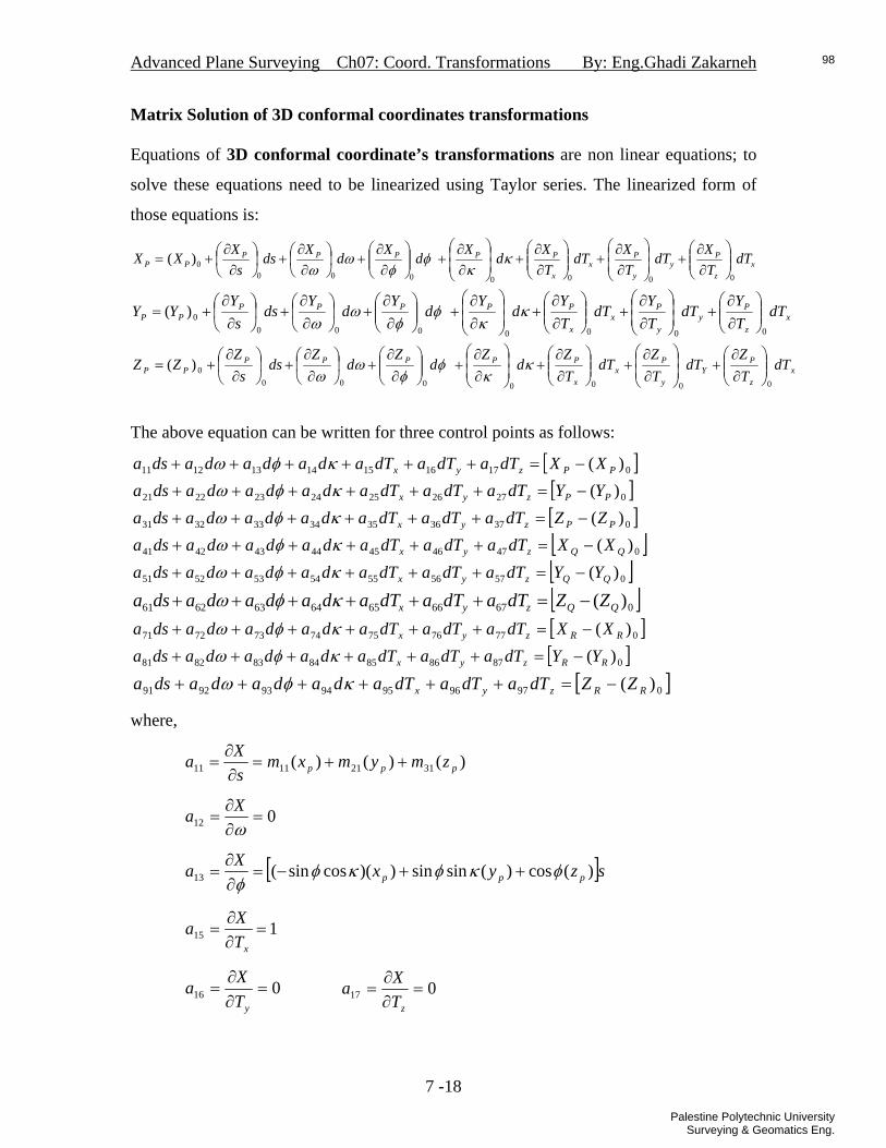
Matrix Solution of 3D conformal coordinates transformations Equations of 3D conformal coordinate’s transformations are non linear equations; to
solve these equations need to be linearized using Taylor series. The linearized form of
those equations is:
xz
Py
y
Px
x
PPPPPPP dT
TXdT
TXdT
TXdXdXdXds
sXXX
00000000)( ⎟⎟
⎠
⎞⎜⎜⎝
⎛∂∂
+⎟⎟⎠
⎞⎜⎜⎝
⎛
∂∂
+⎟⎟⎠
⎞⎜⎜⎝
⎛∂∂
+⎟⎟⎠
⎞⎜⎜⎝
⎛
∂∂
+⎟⎟⎠
⎞⎜⎜⎝
⎛∂∂
+⎟⎠⎞
⎜⎝⎛∂∂
+⎟⎠⎞
⎜⎝⎛∂∂
+= κκ
φφ
ωω
xz
Py
y
Px
x
PPPPPPP dT
TY
dTTY
dTTY
dY
dY
dY
dss
YYY
00000000)( ⎟⎟
⎠
⎞⎜⎜⎝
⎛∂∂
+⎟⎟⎠
⎞⎜⎜⎝
⎛
∂∂
+⎟⎟⎠
⎞⎜⎜⎝
⎛∂∂
+⎟⎟⎠
⎞⎜⎜⎝
⎛
∂∂
+⎟⎟⎠
⎞⎜⎜⎝
⎛∂∂
+⎟⎠
⎞⎜⎝
⎛∂∂
+⎟⎠
⎞⎜⎝
⎛∂∂
+= κκ
φφ
ωω
xz
PY
y
Px
x
PPPPPPP dT
TZ
dTTZ
dTTZ
dZ
dZ
dZ
dss
ZZZ
00000000)( ⎟⎟
⎠
⎞⎜⎜⎝
⎛∂∂
+⎟⎟⎠
⎞⎜⎜⎝
⎛
∂∂
+⎟⎟⎠
⎞⎜⎜⎝
⎛∂∂
+⎟⎟⎠
⎞⎜⎜⎝
⎛
∂∂
+⎟⎟⎠
⎞⎜⎜⎝
⎛∂∂
+⎟⎠
⎞⎜⎝
⎛∂∂
+⎟⎠
⎞⎜⎝
⎛∂∂
+= κκ
φφ
ωω
The above equation can be written for three control points as follows:
[ ]017161514131211 )( PPzyx XXdTadTadTadadadadsa −=++++++ κφω[ ]027262524232221 )( PPzyx YYdTadTadTadadadadsa −=++++++ κφω[ ]037363534333231 )( PPzyx ZZdTadTadTadadadadsa −=++++++ κφω[ ]047464544434241 )( QQzyx XXdTadTadTadadadadsa −=++++++ κφω[ ]057565554535251 )( QQzyx YYdTadTadTadadadadsa −=++++++ κφω
[ ]067666564636261 )( QQzyx ZZdTadTadTadadadadsa −=++++++ κφω[ ]077767574737271 )( RRzyx XXdTadTadTadadadadsa −=++++++ κφω[ ]087868584838281 )( RRzyx YYdTadTadTadadadadsa −=++++++ κφω
[ ]097969594939291 ( )RRzyx ZZdTadTadTadadadadsa −=++++++ κφω
where,
)()()( 31211111 ppp zmymxmsXa ++=∂∂
=
012 =∂∂
=ωXa
[ ]szyxXa ppp )(cos)(sinsin))(cossin(13 φκφκφφ
++−=∂∂
=
115 =∂∂
=xT
Xa
016 =∂∂
=yT
Xa 017 =∂∂
=zT
Xa
7 -18
98
Palestine Polytechnic UniversitySurveying & Geomatics Eng.

Advanced Plane Surveying Ch07: Coord. Transformations By: Eng.Ghadi Zakarneh
)()()( 32221221 ppp zmymxmsYa ++=∂∂
=
[ ]szmymxmYa ppp )()()( 33231322 −−−=∂∂
=ω
[ ]szyxYa ppp ))(sin(sin)(sincossin())(coscossin(23 φωκφωκφωφ
+−+−=∂∂
=
[ ]symxmYa pp )()( 122224 −=∂∂
=κ
025 =∂∂
=xT
Ya 126 =∂∂
=yT
Ya 027 =∂∂
=zT
Ya
)()()( 33231331 ppp zmymxmsZa ++=∂∂
=
[ ]szmymxmZa ppp )()()( 32221232 ++=∂∂
=ω
[ ]szyxZa ppp ))(sincos()(sincos(cos))(coscoscos(33 φωκφωκφωφ
−++−=∂∂
=
[ ]symxmZa pp )()( 132334 −=∂∂
=κ
035 =∂∂
=xT
Za 036 =∂∂
=yT
Za 137 =∂∂
=ZT
Za
In this solution we intial values of the unknowns (scale factor , 3 rotations, 3
translations). Using these value we calculate the coordinates of the common points:
, , using the 3D-conformal equations: 0)( PX 0)( PY 0)( PZ
The final estimate for those parameters is reached iteratively.
7 -19
99
Palestine Polytechnic UniversitySurveying & Geomatics Eng.
Advanced Plane Surveying Ch07: Coord. Transformations By: Eng.Ghadi Zakarneh
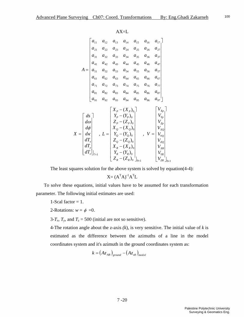
AX=L
⎥⎥⎥⎥⎥⎥⎥⎥⎥⎥⎥⎥
⎦
⎤
⎢⎢⎢⎢⎢⎢⎢⎢⎢⎢⎢⎢
⎣
⎡
=
97969594939291
87868584838281
77767574737271
67666564636261
57565554535251
47464544434241
37363534333231
27262524232221
17161514131211
aaaaaaaaaaaaaaaaaaaaaaaaaaaaaaaaaaaaaaaaaaaaaaaaaaaaaaaaaaaaaaa
A
17×⎥⎥⎥⎥⎥⎥⎥⎥
⎦
⎤
⎢⎢⎢⎢⎢⎢⎢⎢
⎣
⎡
=
z
y
x
dTdTdTdddds
X κφω
, ,
190
0
0
0
0
0
0
0
0
)()()()()()()()()(
×⎥⎥⎥⎥⎥⎥⎥⎥⎥⎥
⎦
⎤
⎢⎢⎢⎢⎢⎢⎢⎢⎢⎢
⎣
⎡
−−−−−−−−−
=
RR
RR
RR
PP
PP
PP
ZZYYXXZZYYXXZZYYXX
L
19×
⎥⎥⎥⎥⎥⎥⎥⎥⎥⎥
⎦
⎤
⎢⎢⎢⎢⎢⎢⎢⎢⎢⎢
⎣
⎡
=
ZR
YR
XR
ZQ
YQ
XQ
Zp
Yp
Xp
VVVVVVVVV
V
The least squares solution for the above system is solved by equation(4-4):
X= (ATA)-1ATL
To solve these equations, initial values have to be assumed for each transformation
parameter. The following initial estimates are used:
1-Scal factor = 1.
2-Rotations: w = φ =0.
3-Tx, Ty, and Tz = 500 (initial are not so sensitive).
4-The rotation angle about the z-axis (k), is very sensitive. The initial value of k is
estimated as the difference between the azimuths of a line in the model
coordinates system and it's azimuth in the ground coordinates system as:
( ) ( ) elabgroundAB AzAzk mod−=
7 -20
100
Palestine Polytechnic UniversitySurveying & Geomatics Eng.

Advanced Plane Surveying Ch07: Coord. Transformations By: Eng.Ghadi Zakarneh
Problems
C-3. Solve C-1 using matrices?
7 -21
101
Palestine Polytechnic UniversitySurveying & Geomatics Eng.

Advanced Plane Surveying Ch07: Coord. Transformations By: Eng.Ghadi Zakarneh
7 -22
102
Palestine Polytechnic UniversitySurveying & Geomatics Eng.

Advanced Plane Surveying Ch08: Survey Operations By: Eng.Ghadi Zakarneh
Ch08 Survey Operations
In Palestine
103
Palestine Polytechnic UniversitySurveying & Geomatics Eng.
104
Palestine Polytechnic UniversitySurveying & Geomatics Eng.

105
Palestine Polytechnic UniversitySurveying & Geomatics Eng.

106
Palestine Polytechnic UniversitySurveying & Geomatics Eng.

107
Palestine Polytechnic UniversitySurveying & Geomatics Eng.

108
Palestine Polytechnic UniversitySurveying & Geomatics Eng.

109
Palestine Polytechnic UniversitySurveying & Geomatics Eng.

110
Palestine Polytechnic UniversitySurveying & Geomatics Eng.

111
Palestine Polytechnic UniversitySurveying & Geomatics Eng.

112
Palestine Polytechnic UniversitySurveying & Geomatics Eng.

113
Palestine Polytechnic UniversitySurveying & Geomatics Eng.

114
Palestine Polytechnic UniversitySurveying & Geomatics Eng.

Advanced Plane Surveying Appendix: Stadia By: Eng.Ghadi Zakarneh
Appendix
A - 1
115
Palestine Polytechnic UniversitySurveying & Geomatics Eng.

Advanced Plane Surveying Appendix: Stadia By: Eng.Ghadi Zakarneh
APPENDIX-A
STADIA 1- Stadia for Level Instrument
A - 2
116
Palestine Polytechnic UniversitySurveying & Geomatics Eng.
Advanced Plane Surveying Appendix: Stadia By: Eng.Ghadi Zakarneh
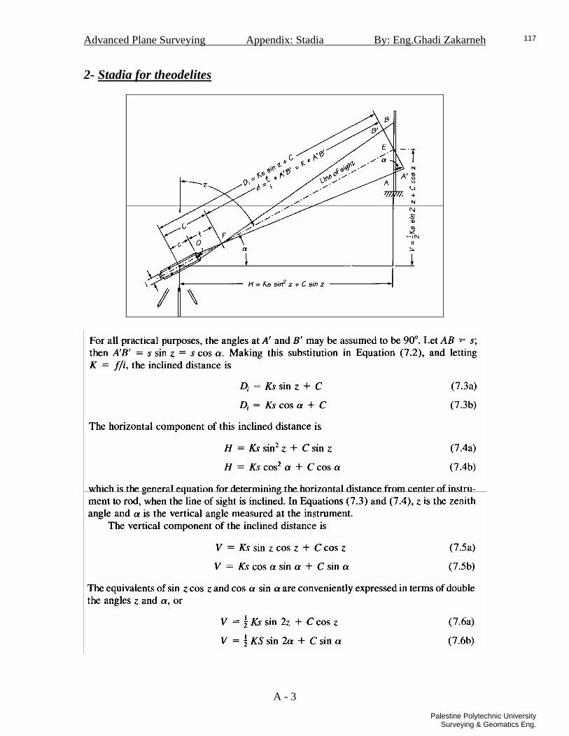
2- Stadia for theodelites
A - 3
117
Palestine Polytechnic UniversitySurveying & Geomatics Eng.

Unit conversions
118
Palestine Polytechnic UniversitySurveying & Geomatics Eng.

119
Palestine Polytechnic UniversitySurveying & Geomatics Eng.
120
Palestine Polytechnic UniversitySurveying & Geomatics Eng.
References 1. Andrew L.Harbin ,”Land Surveyor Reference Manual”, 2nd edition,1998. 2. James M. Anderson & Edward Michail ,”Surveying theory and practice”, 7th
edition,1998.
3. Najeh S. Tamim,” Surveying for Engineers”, 2nd edition, 2006.
4. Paul R. Wolf & Bon A. Dewitt,” Elements of Photogrammetry with application in GIS”, 3rd edition, 2000.
5. Paul R. Wolf & Charles D. Ghilani ,”Elementary Surveying: An Introduction to
Geomatics”; 11th edition,2006.
6. Paul R. Wolf & Russell C. Brinkerl ,”Elementary Surveying”, 9th edition,2002.
121
Palestine Polytechnic UniversitySurveying & Geomatics Eng.

122
Palestine Polytechnic UniversitySurveying & Geomatics Eng.
123
Palestine Polytechnic UniversitySurveying & Geomatics Eng.
124
Palestine Polytechnic UniversitySurveying & Geomatics Eng.

125
Palestine Polytechnic UniversitySurveying & Geomatics Eng.

126
Palestine Polytechnic UniversitySurveying & Geomatics Eng.

127
Palestine Polytechnic UniversitySurveying & Geomatics Eng.

128
Palestine Polytechnic UniversitySurveying & Geomatics Eng.

129
Palestine Polytechnic UniversitySurveying & Geomatics Eng.

130
Palestine Polytechnic UniversitySurveying & Geomatics Eng.
131
Palestine Polytechnic UniversitySurveying & Geomatics Eng.