collimation optimizations, capture efficiency, and primary
TRANSCRIPT

1
SLAC-PUB-12798 September 2007
(A)
Collimation Optimizations, Capture Efficiency, and Primary-beam Power Loss in the ILC Positron Source Transport*
F. Zhou, Y. Nosochkov, and J. C. Sheppard
SLAC, 2575 Sand Hill Road, Menlo Park, CA 94025, USA
W. Liu Argonne National Lab, Argonne, IL 65014, USA
Abstract
The ILC positron beam generated from a thin Ti target has a wide energy spread and large transverse divergence. With the collection optics immediately downstream of the target and pre-acceleration to 125 MeV, the collected positron beam still has a long tail of positrons with low energies and large transverse divergence, which will be lost in the rest of the ILC positron source beamline. A collimation system is proposed and optimized for the case of a shielded target with quarter-wave transformation collection optics so that the power loss in the magnets and RF structures is effectively controlled within the acceptable level and in the damping ring (DR) within 640 W, assuming 3×10¹⁰ of the captured positrons per bunch in the DR. In this case, the capture efficiency and DR injection efficiency are 13% and 99.8%, respectively. The lower capture efficiency is expected to result in higher injection efficiency and therefore, a lower power loss in the DR. The capture efficiency for the cases of a shielded target with flux concentrator and 5-T immersed target with flux concentrator is 20% and 30%, respectively, with the collimation system.
* Work supported by DOE contract DE-AC02-76SF00515
2
Collimation Optimizations, Capture Efficiency, and Primary-beam Power Loss in the ILC Positron Source Transport
F. Zhou, Y. Nosochkov, and J. C. Sheppard
SLAC, 2575 Sand Hill Road, Menlo Park, CA 94025, USA
W. Liu Argonne National Lab, Argonne, IL 65014, USA
Abstract
The ILC positron beam generated from a thin Ti target has a wide energy spread and large transverse divergence. With the collection optics immediately downstream of the target and pre-acceleration to 125 MeV, the collected positron beam still has a long tail of positrons with low energies and large transverse divergence, which will be lost in the rest of the ILC positron source beamline. A collimation system is proposed and optimized for the case of a shielded target with quarter-wave transformation collection optics so that the power loss in the magnets and RF structures is effectively controlled within the acceptable level and in the damping ring (DR) within 640 W, assuming 3×10¹⁰ of the captured positrons per bunch in the DR. In this case, the capture efficiency and DR injection efficiency are 13% and 99.8%, respectively. The lower capture efficiency is expected to result in higher injection efficiency and therefore, a lower power loss in the DR. The capture efficiency for the cases of a shielded target with flux concentrator and 5-T immersed target with flux concentrator is 20% and 30%, respectively, with the collimation system. 1. Overview of the ILC positron source beam optics The 150 GeV International Linear Collider (ILC) electron beam passing through an undulator generates circularly polarized photons, which impinge on a thin Ti target and produce longitudinally polarized positrons. The generated positron beam is first collected and accelerated to 125 MeV through a beamline TAP. Then a dogleg, PCAP, is used to separate positrons from electrons and photons. Positrons are accelerated to 400 MeV in the normal conducting (N.C.) pre-acceleration linac, PPA. The 400 MeV beam passes through a beamline, PPATEL, to the electron main linac tunnel. Then the positron beam transports through a beamline, PTRAN, from the electron main linac tunnel to the positron superconducting (S.C.) booster linac, PBSTR. After acceleration to 5 GeV, it is transported from the PBSTR Linac to Ring (LTR) performing spin rotations and energy compression, and finally enters the damping ring (DR) injection line. The overall geometry of the positron source is shown in Fig. 1. The optics details are described in Refs. [1-2]. This technical note is organized as follows: section 2 describes the proposed collimation system for the positron transport line; section 3 presents the start-to-end primary-beam tracking with the collimation system, and the results of power loss and

3
capture efficiency for the cases of different field on the target and collection optics; and finally a short summary is presented.
0 1000 2000 3000 4000 50005
5
15
25
35
45
55
65
75
85
95
105
surveynn 1,
surveynn 2,
surveynn 0,
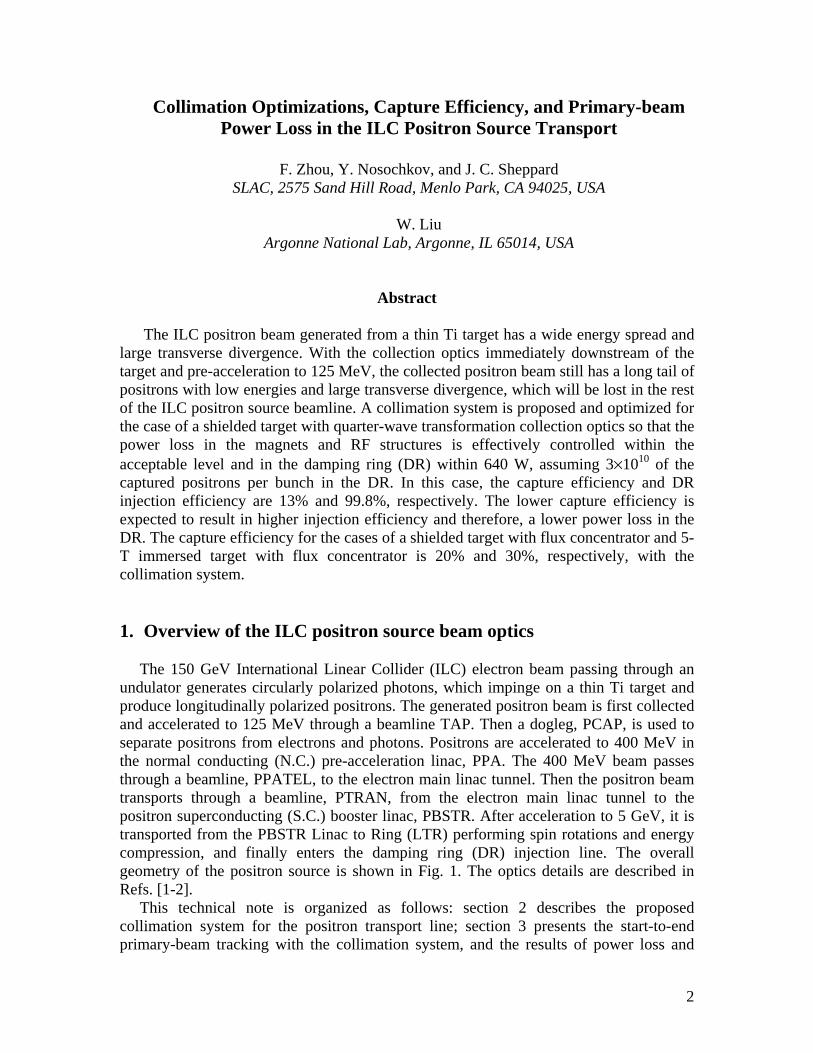
FIG. 1. Overall geometry of the ILC positron source; the beamline TAP is not shown. 2. Optimized collimation system A collimation system is designed to reduce the beam power loss in the beamline elements (e.g. magnets, RF structures, and drift beam tube) to an acceptable level, typically smaller than 100 W/m and 1 W/m for N.C. and S.C. elements, respectively, without a severe loss of capture efficiency of the positron source transport. Here, we define the capture efficiency as the number of positrons captured inside the DR acceptance divided by the initial number of positrons at the target. The positron beam entering the transport line has a long tail characterized by low energy and large divergence. Without the beam collimation, the beam loss in the beamline elements would severely exceed the acceptable level, particularly in the first three sections: the PCAP, PPA, and PPATEL system. Following the preliminary design of collimation system in [3], total of eleven collimators are proposed in the PCAP, PPA, and PPATEL, as shown in Fig. 2. The first four collimators in the beginning of PCAP are used for betatron amplitude collimation of the incoming positrons with large transverse amplitudes and angles, while the next four collimators positioned in the dispersive areas are mainly used to clip off the low energy tail. The combination of the ninth and tenth collimators is to effectively reduce the beam loss in the N.C. RF structures in the PPA immediately downstream of the PCAP. The eleventh collimator placed at the dispersive location in the PPATEL is to decrease the beam power loss in the magnets below 100 W/m. In principle, the final collimation of the positrons which are beyond the DR transverse acceptance can
X (m)
Y (m)
Z (m)
PCAP, PPA, and PPATEL
PTRANPBSTR
PLTR
4
be done in the 5-GeV LTR section immediately upstream of the DR, but due to the high beam energy the power load on the LTR collimators would be relatively high. Instead, the collimation of the positrons beyond the DR transverse acceptance, 09.0≤+ yx AA m, is performed in the lower energy region, ≤400 MeV, by extensively optimizing the apertures of the first eleven collimators. With the current optics configuration, the collimation of the positrons beyond the DR longitudinal acceptance,
≤Δ×Δ zE (±25MeV)×(±3.46cm), has to be done at the LTR. Total of five energy collimators indexed from 12th to 16th are used for this purpose. Parameters of the complete collimation system along the positron transport are shown in the Table I. All collimators are assumed rectangular.
FIG. 2. Optics with eleven collimators in the PCAP, PPA, and PPATEL.
FIG. 3. Optics with five collimators in the 5-GeV LTR.

5
Table I. Parameters of the rectangular collimators.
Collimator index Half aperture in x/y (mm)
Length (cm)
Entrance location s (m)
In PCAP beamline C1 C2 C3 C4 C5 C6 C7 C8 C9 C10
15/15 28/25
22/22.5 38/25 23/75 25/75 30/60 42/18 23/30 16/16
10 10 10 10 10 10 10 10 10 10
0.2 1.0 2.6 4.27
10.321 11.570 12.320 15.319 61.672 64.792
In PPATEL beamline C11
15/7.5
8
109.292
In LTR beamline C12 C13 C14 C15 C16
23/35 30/35 20/35 7.4/35 10.5/35
20 30 60 50 60
5501.887 5579.153 5579.756 5583.350 5587.643
Table II. Physical apertures of the beamline.
Components Half aperture in x/y (cm) Capture section 2.3/2.3 PCAP 7.5/7.5 PPA 2.3/2.3
PPATEL 7.5/7.5 PTRAN 7.5/7.5 PBSTR 3.7/3.7
LTR RF section
solenoid others
3.7/3.7 2.0/2.0 7.5/3.5

6
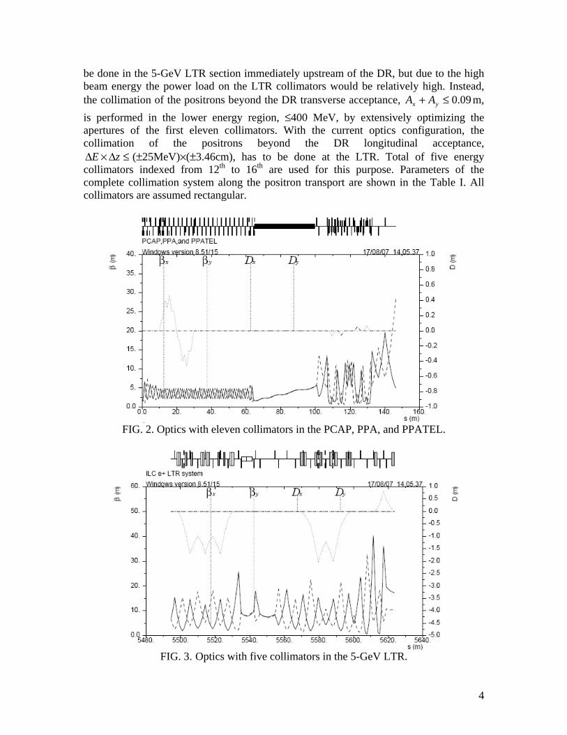
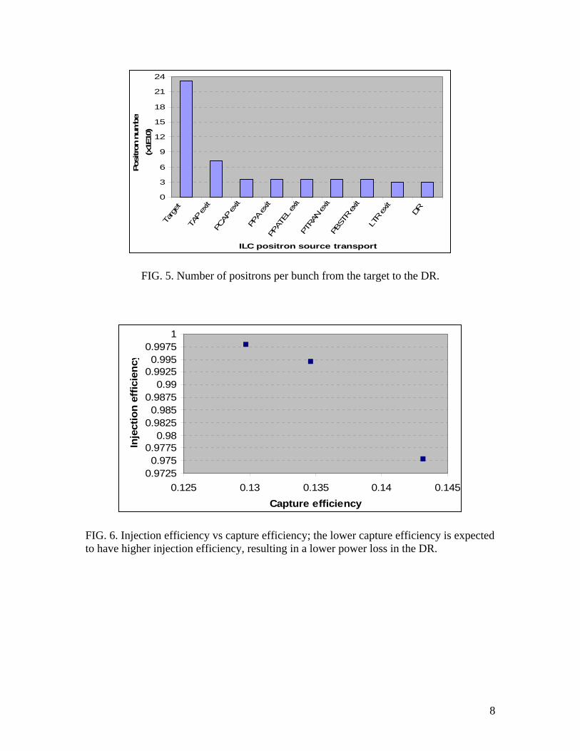
3. Primary-beam power loss and capture efficiency Primary-beam tracking from a thin Ti target to the entrance of the DR injection line has been performed. The tracking from the target to the capture section (125 MeV) is described in Ref. [4]. The Elegant code [5] is used to track the positron beam through the rest of the beamline including the PCAP, PPA, PPATEL, PTRAN, PBSTR, and finally the LTR system. Positron 6-D coordinates at the exit of the capture section are used as the input data for the Elegant code tracking. Note that only the positrons in the main RF bucket are selected for the tracking. Due to the extremely large energy spread in the beginning of the beamline, the tracking was set up to calculate energy dependence to all orders in the magnets from PCAP to PTRAN sections, and then to the 2nd order for the rest of the transport, where the energy spread is reduced. To maximize the number of positrons within the DR acceptance, the energy compression in the LTR is fully optimized before the positrons reach the DR injection line. For that purpose, the booster linac PBSTR upstream of the LTR runs its RF phase off-crest to create a suitable correlated energy spread. The collimation system described in the previous section is implemented and the physical apertures of the beamline listed in Table II are used in the tracking. The full beam power is 320 kW at the 5-GeV DR based on the ILC beam parameters – 3×10¹⁰ of captured positrons in the DR per bunch (50% more than the design value at the IP), 2670 bunches per pulse, and 5 Hz pulse repetition. The primary-beam power loss along the beamline is shown in Fig. 4 for the case of a shielded target with quarter-wave transformation optics. It is shown that the significant power loss is dissipated in the sixteen collimators, and the power loss in N.C. components and S.C. booster linac is within 100 W/m and 1 W/m, respectively. The number of positrons per bunch along the transport shown in Fig. 5 is used for the power loss calculation. The power loss in the five LTR collimators is about 5.5 kW, 10.7 kW, 13 kW, 15.6 kW, and 5 kW, respectively, and in the DR it is 0.64 kW. 13% of the positrons from the target survive the transport through the complete beamline, and 99.8% of the injected positrons are captured within the DR 6-D acceptance, corresponding to 12.97% of positrons from the target captured in the DR. Without the collimation system, the capture efficiency is 16.8%. Thus, 3.8% of capture efficiency is lost when the collimation system is used. The higher injection efficiency (i.e., the number of positrons captured in the DR divided by the injected positrons in the DR) corresponding to a lower power loss in the DR is expected to result in lower capture efficiency, as shown in Fig. 6. Fig. 7 shows the 6-D phase space at the entrance of the DR injection without (left) and with (right) the collimation system, where the positrons in red and green are beyond the DR transverse and longitudinal acceptance, respectively. Tracking for various kinds of scenarios, such as immersed vs shielded target, flux concentrator vs quarter-wave transformation, is extensively conducted. The capture efficiency for the different field on the target and collection optics with and without the collimation system is shown in Fig. 8. It shows that the capture efficiency for the cases of a shielded target with flux concentrator and 5-T immersed target with flux concentrator is 20% and 30%, respectively.

7
0.1 1 10 100 1 .103 1 .1040.1
1
10
100
1 .103
1 .104
1 .105
powerpp 1,
powerpp 0,
5400 5450 5500 5550 56000.1
1
10
100
1 .10 3
1 .10 4
1 .10 5
power pp 1,
power pp 0,
FIG. 4. Primary-beam power loss along the complete positron source transport (top) and the LTR (bottom) given 3×10¹⁰ of the captured positrons in the DR; total of 16 collimators are implemented which absorb most of the power loss.
W/m
Path length (m)
W/m
Path length (m)
8
0
3
6
9
12
15
18
21
24
Targ
et
TAP
exit
PCAP
exit
PPA
exit
PPAT
EL ex
it PT
RAN
exit
PBST
R ex
it
LTR
exit
DR
ILC positron source transport
Posi
tron
num
ber
(x1E
10)
FIG. 5. Number of positrons per bunch from the target to the DR.
0.97250.975
0.97750.98
0.98250.985
0.98750.99
0.99250.995
0.99751
0.125 0.13 0.135 0.14 0.145Capture efficiency
Inje
ctio
n ef
ficie
ncy
FIG. 6. Injection efficiency vs capture efficiency; the lower capture efficiency is expected to have higher injection efficiency, resulting in a lower power loss in the DR.
9
0.015 0 0.0150.001
0
0.001
longii 1,
testbadi 1,
longibadi 1,
longii 0, testbadi 0,, longibadi 0,,
0.015 0 0.0150.001
0
0.001
longii 1,
testbadi 1,
longibadi 1,
longii 0, testbadi 0,, longibadi 0,,
0.015 0 0.015
0.001
0
0.001
longii 3,
testbadi 3,
longibadi 3,
longii 2, testbadi 2,, longibadi 2,, 0.015 0 0.015
0.001
0
0.001
longii 3,
testbadi 3,
longibadi 3,
longii 2, testbadi 2,, longibadi 2,,
1.875812.10 5 1.875826.10 5 1.87584.10 59500
9600
9700
9800
longii 5,
testbadi 5,
longibadi 5,
longii 4, testbadi 4,, longibadi 4,, 1.875812.10 5 1.875825.10 5 1.875839.10 5
9500
9600
9700
9800
longii 5,
testbadi 5,
longibadi 5,
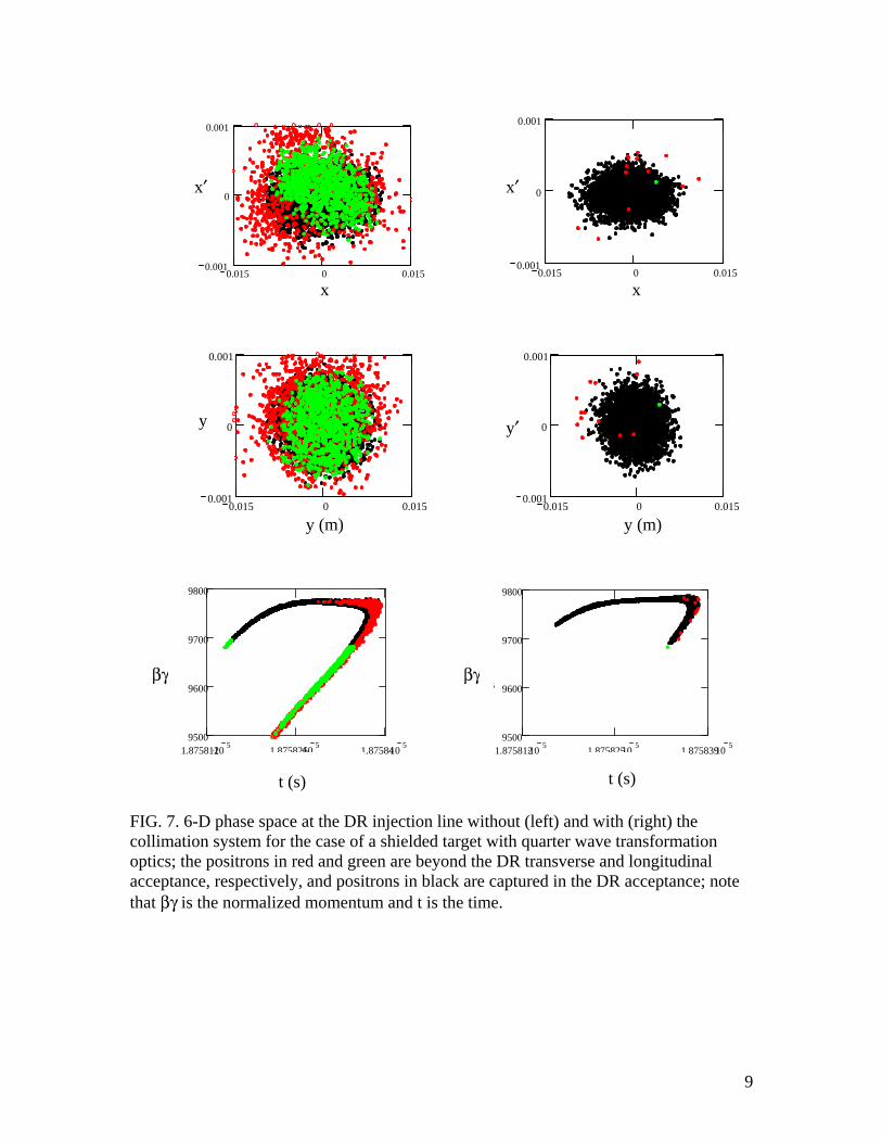
longii 4, testbadi 4,, longibadi 4,, FIG. 7. 6-D phase space at the DR injection line without (left) and with (right) the collimation system for the case of a shielded target with quarter wave transformation optics; the positrons in red and green are beyond the DR transverse and longitudinal acceptance, respectively, and positrons in black are captured in the DR acceptance; note that βγ is the normalized momentum and t is the time.
x′ x′
x x
y′
y′
y (m) y (m)
βγ βγ
t (s) t (s)

10
05
101520253035
Shielded target & Quarter-wavetransformation(w/ collimation)
Shielded target & Quarter-wavetransformation
(w/o collimation)
Shielded target &Flux concentrator
(w/ collimation)
5T Immersedtarget & Flux
concentrator (w/ collimation)
Cap
ture
eff
icie
ncy
(%
FIG. 8. Capture efficiency for different field on the target and collection optics with and without the collimation system optimized for the case of a shielded target with quarter-wave transformation optics.
4. Summary A collimation system for the positron source transport is optimized for the case of a shielded target with quarter wave transformation collection optics. The primary-beam tracking shows that with the collimation system the beam power loss in the transport line can be controlled within the acceptable level and the power loss in the DR is 640 W for 3×10¹⁰ of captured positrons per bunch in the DR. The corresponding injection efficiency and the capture efficiency is 99.8% and 13%, respectively. The lower capture efficiency is expected to result in higher injection efficiency and therefore, a lower power loss in the DR. The capture efficiency for the cases of a shielded target with flux concentrator optics and a 5-T immersed target with flux concentrator is 20% and 30%, respectively, with the collimation system. Further tracking studies including both the primary and secondary particles and optimization of beamline physical apertures to meet the engineering design are needed. We would like to thank Drs. V. Bharadwaj and W. Gai for helpful discussion. References [1] F. Zhou, et al., “Start-to-end beam optics development and multi-particle tracking for
the ILC undulator-based positron source”, SLAC-PUB-12239, Jan. 2007. [2] F. Zhou, et al., “Transport optics design and multi-particle tracking for the ILC
positron source”, PAC07, Albuquerque. [3] Y. Nosochkov, www.slac.stanford.edu/~yuri/ilc/ [4] W. Liu, et al., “Systematic study of undulator based ILC positron source: production
and capture”, PAC 2007, Albuquerque, June 2007. [5] M. Borland, “Elegant: A flexible SDDS-compliant code for an accelerator
simulation”, APS LS-287, ANL, 2000.