colston cross near axminster devon ex13 7nf · colston cross near axminster devon ex13 7nf ... for...
TRANSCRIPT

Page 1 Electrofrog Point wiring published by Buffers Model Railways Ltd Author Steve Fuller Copyright 2011
Colston Cross near Axminster Devon EX13 7NF (On A358 between Chard & Axminster) email us: [email protected]
FREE ON SITE PARKING OPENING TIMES TUESDAYSATURDAY 10AM4PM
LIVE FROG POINTS AND HOW TO UPGRADE THEM
Live frog points Why?
The main benefit that we get from using live frog points (Peco Electrofrog) is that the track current is not lost over any large area of the point. This means that locomotives, even those with few pickups, can negotiate the point without stuttering or stop ping due to lack of power. This is even more important if we run DCC sound stock on our layouts as intermittent silence does nothing for the realism it is meant to portray. The ability to run slowly over pointwork is equally feasible whether you are a DC (analogue) or a DCC (digital) modeller.
The extra wiring involved is not difficult even for those that have little experience at wiring and soldering. Even if you are not going to be using Electrofrog points this document is still worth a read as it may well help those using Insulfrogs.
Open turnout
Closed turnout
Facing Track
Tie Bar
Frog
Switch blades
Stock Rails
Anatomy of a model railway turnout/point
Before we get into the whys and wherefores here is a useful list of tools.
Soldering Iron and solder (our Antex 18w or 25watt irons are ideal for this job. Wire in different colours we opted for Brown, Yellow and Orange for this exercise Some side cutters (flat cut are best see Expo range) Wire strip pers
live frog points have all there switching rails bonded together by wiring installed underneath at the factory. This means cur rent can flow over the entire point giving smoother and bet ter running. Because of this “extra bonding” current is carried through the point by the action of the blades making contact with the stock rails and feeding forward via the bonding and out over the frog. Most noticeable is the lack of insulation where the point vees out to the open and closed sections of the turnout the rails being all metal in this area. One thing we do need to bear in mind is that we need to make sure that the exit rails after the frog are connected to the track they service using Insulated Rail Joiners more commonly called IRJ’s.
We can further improve the reliability with a little additional wiring and modification which will reap benefits in improved running and removes the need to rely on the point blades making the connection for us.
The process involves adding extra bonding and extending the factory installed wiring via a connection to our points motor. For those who use a different form of point operation a micro switch can be mounted on the end of the tie bar to perform the same function.
Dead frog points (Pecos Insufrog) do not have the same type of bonding around the frog area and are instantly recognis able by the small plastic insulation joint where the exit rails
meet the frog. They also need good contact between the point blades in order to work reliably, but unlike their Electrofrog cousins do not require IRJs fitting thanks to the aforementioned insulation. As a matter of interest insulfrog points can also be improved in a similar way to that explained below and can even be converted to full electro frog versions with a little extra work and some spare rail.
Performing the upgrade detailed here will be the single biggest performance enhancement you will make to your trackwork and is very much worth every minute spent doing the work involved and considering it only takes a few minutes it is also very time efficient as well.
Insulfrog: note insulators Electrofrog: note no insulator
How to recognise an live frog

Page 2 Electrofrog Point wiring published by Buffers Model Railways Ltd Author Steve Fuller Copyright 2011
Principally the idea is to make everything in the point ‘hot’ with the correct polarity voltage for the direction that the point is set.
IRJ
IRJ
Wire stripping Tip
When you strip the wire for connecting to your point motors and switches or any other terminal for that matter, don’t just strip and remove the insulation. Using your preferred strippers cut the insulation but do not fully remove it from the wire now twist the separated piece of insulation as you slowly pull it free. This twists the copper strands really tight and prevents stray ends from being missed.
In the diagram above the point is set to the straight ahead position.
The rails marked in blue for arguments sake are negative and those in red are positive.
Because we have all rails hard wired via the point motor accessory switch there will be no stalling of the locomotive as it transitions the point work and as you can clearly see we need those insulated rail joiners at the end of the points frog to stop a short circuit as Indicated by “IRJ” in the diagram.
As the train passes from left to right over our point there is no risk of a short as all the track work on the section is cor rectly polarised.
When we switch the point over to select the run off the frog area is switched to the opposite, but correct, polarity for the run off and as before our train passes unhindered by dead spots.
This requires that a little extra wiring is made just to insure that we have the most reliable functionality and that’s what we’ll cover in the next few pages.
Livefrog: Notice the wire running between the two frogs then out toward the top in the groove provided in the sleep er? This bonds the whole frog together and provides a wire for us to use with our point motor on board auxillary switch. Also the rails have a split in them (right inset picture) which is also bonded closed by more silver wires
Deadfrog: the frogs are wired to carry current to the correct exit at the correct polarity and there are solid rails toward the blades (far right inset picture) no additional special wiring is need in order to use this, but improvements can also be made with some imagination and the details included here for Electofrogs.
Electrofrog and Insulfrog, Disecting the Frog what's going on under the skin.

Page 3 Electrofrog Point wiring published by Buffers Model Railways Ltd Author Steve Fuller Copyright 2011
1
So lets get wiring
You need a length of wire (about 30cm) with one end stripped of its insulation to about 3.5 4cm from the end. This should be twisted tight and then tinned with solder.
2
3 Locate the bridging point as shown above and solder this wire across all rails. We have enlarged the solder joints so you can see this more clearly. Yours would ideally be smaller blobs than this if using the right size solder.
Now connect the other end of the wire to the extended part of the manufacturers bonding wire as shown top left.
Then cut the wire where it meets the track edge in step 2 (shown at the bottom of the picture).
4
Finishing off the point.
Now, as shown cut the “all rail bonding” you made in step 1 by removing the centre bond and any stray ends. You can then file down the solder if you wish to make the job nice and neat. Most of you work is hidden if ballasting your layout anyway.
Just along from your rail bond there are two links that connect the closing rails to the frogs, these need to be cut and can actually be pulled free with care using some quality pin nose pliers.
Tidy and ready for installation on the layout. When you install this you will need to drill a hole close the manufacturers bonded con nection wire so that it passes to the under side of the base board, Thankfully new items are coming with longer bonding wires so the soldered joint falls under the board itself and not the point.
Cut here
Page 4 Electrofrog Point wiring published by Buffers Model Railways Ltd Author Steve Fuller Copyright 2011
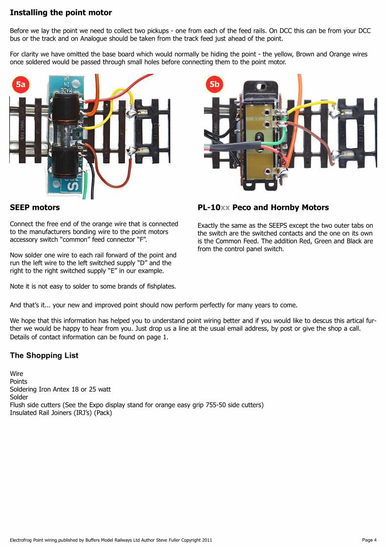
5a 5b
Installing the point motor
Before we lay the point we need to collect two pickups one from each of the feed rails. On DCC this can be from your DCC bus or the track and on Analogue should be taken from the track feed just ahead of the point.
For clarity we have omitted the base board which would normally be hiding the point the yellow, Brown and Orange wires once soldered would be passed through small holes before connecting them to the point motor.
SEEP motors
Connect the free end of the orange wire that is connected to the manufacturers bonding wire to the point motors accessory switch “common” feed connector “F”.
Now solder one wire to each rail forward of the point and run the left wire to the left switched supply “D” and the right to the right switched supply “E” in our example.
Note it is not easy to solder to some brands of fishplates.
PL10xx Peco and Hornby Motors
Exactly the same as the SEEPS except the two outer tabs on the switch are the switched contacts and the one on its own is the Common Feed. The addition Red, Green and Black are from the control panel switch.
And that’s it... your new and improved point should now perform perfectly for many years to come.
We hope that this information has helped you to understand point wiring better and if you would like to descus this artical fur ther we would be happy to hear from you. Just drop us a line at the usual email address, by post or give the shop a call. Details of contact information can be found on page 1.
The Shopping List
Wire Points Soldering Iron Antex 18 or 25 watt Solder Flush side cutters (See the Expo display stand for orange easy grip 75550 side cutters) Insulated Rail Joiners (IRJ’s) (Pack)