combat vehicle r&d- networks · - joint technical architecture (jta) - dod information...
TRANSCRIPT

unclassified
unclassified
Combat Vehicle R&D- NetworksTank Automotive Research, Development & Engineering Center
Mr. Magid Athnasios, Executive Director of Engineering
1Distribution A approved for Public Release; distribution Unlimited, per AR 380-5.
OPSEC Review conducted per AR 530-1 and HQ TACOM OPSEC SOP # 21309

unclassified
unclassified
It’s All About the Warfighter
2
unclassified
unclassified
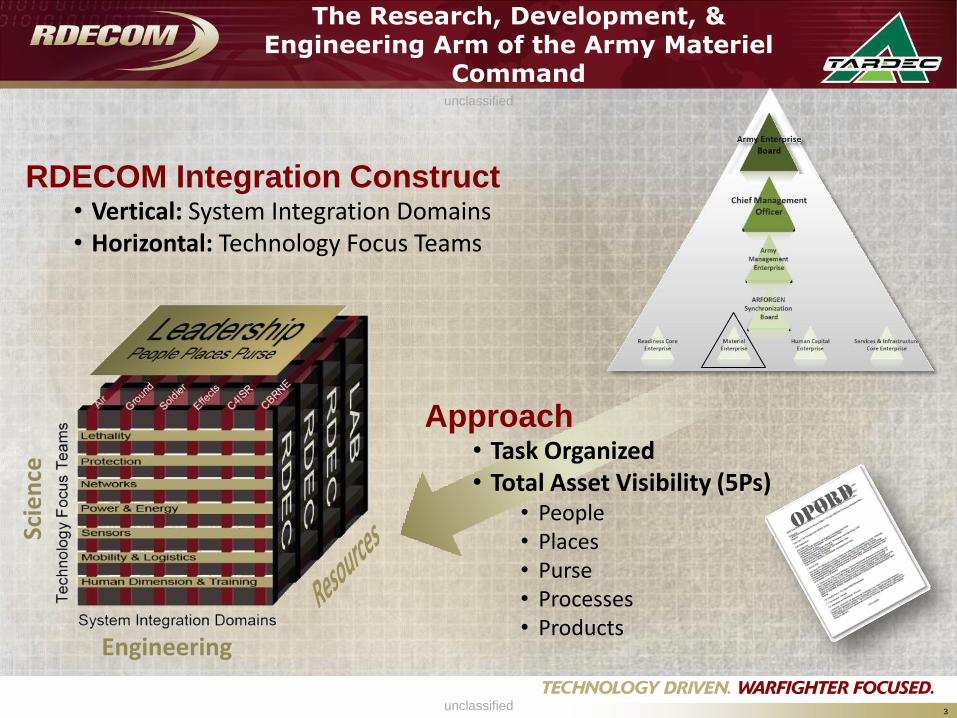
The Research, Development, & Engineering Arm of the Army Materiel
Command
3
RDECOM Integration Construct• Vertical: System Integration Domains• Horizontal: Technology Focus Teams
Approach• Task Organized• Total Asset Visibility (5Ps)
• People• Places• Purse• Processes• Products
Engineering
Scie
nce

unclassified
unclassified
Protection Roadmap
Power & Energy Roadmap
Lethality Roadmap
Sensors Roadmap
Network Roadmap
Human Dimension & Trng Roadmap
Mobility & Logistics Roadmap
ONS
JUONS
War
Fighter
Objectives
Ground Systems IntegrationSynchronization of Data
FUE/IOC
(1 HBCT)
3QFY18
FUE/IOC
(1 HBCT)
3QFY18Development Test
Prototype Tanks (7)
MS B
Development (SDD)
MS C FRPD
Trade Studies and Analysis
Abrams Evolutionary System Definition
TechnologyMaturation/Evaluation
CDR
LRIP Lead time
PVT/IOT&E/LFT&E
Deliveries
Abrams
Evolutionary
Design
Production Lead time
20182017201620152014201320122011201020092008FY 20182017201620152014201320122011201020092008FY
Design Phase I (BAE Systems IR&D)
Full Scale Development Government Vehicle Testing PIM ExecutionPaladin PIM
FUE
MS B
Development
Test
Prototype
Fabrication
Development (SDD)
MS C
Bradley Evolutionary System Definition
Technology Maturation/Evaluation
Production Long Lead
LRIP
PVT/IOT&E/LFT&E
Long Lead
FRPD
FUE/IOC
(1 HBCT)
1QFY18
Bradley
Evolutionary
Design
Preliminary Modernization Timeline (based on 2008 schedules)
CDR
Tech Development
PDR
PM HBCT SchedulesDepartment
of Army
(DA)
PEO GCS
Joint
Vision
2020
Ground Systems Integration
Domain
Synchronized Views
•Capability Based
•Time Opportunity Based
•Resource Based
4
unclassified
unclassified
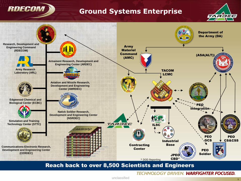
Ground Systems Enterprise
5
Army
Materiel
Command
(AMC)
TACOM
LCMC
(ASA(ALT))
ILSC
Contracting
Center
Industrial
Base
PEO
GCS
PEO
CS&CSS
PEO
Soldier
PEO
Integration
Department of
the Army (DA)
Armament Research, Development and
Engineering Center (ARDEC)
Army Research
Laboratory (ARL)
Edgewood Chemical and
Biological Center (ECBC)
Aviation and Missile Research,
Development and Engineering
Center (AMRDEC)
Natick Soldier Research,
Development and Engineering Center
(NSRDEC)
Communications-Electronic Research,
Development and Engineering Center
(CERDEC)
Simulation and Training
Technology Center (STTC)
Reach back to over 8,500 Scientists and Engineers
Research, Development and
Engineering Command
(RDECOM)
JPEO
CBD** DOD Reporting
unclassified
unclassified
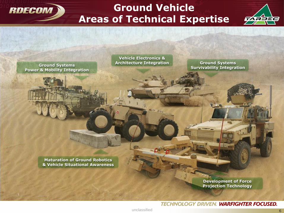
Ground Vehicle Areas of Technical Expertise
6
Ground Systems Power & Mobility Integration
Maturation of Ground Robotics & Vehicle Situational Awareness
Vehicle Electronics &Architecture Integration Ground Systems
Survivability Integration
Development of Force Projection Technology
unclassified
unclassified
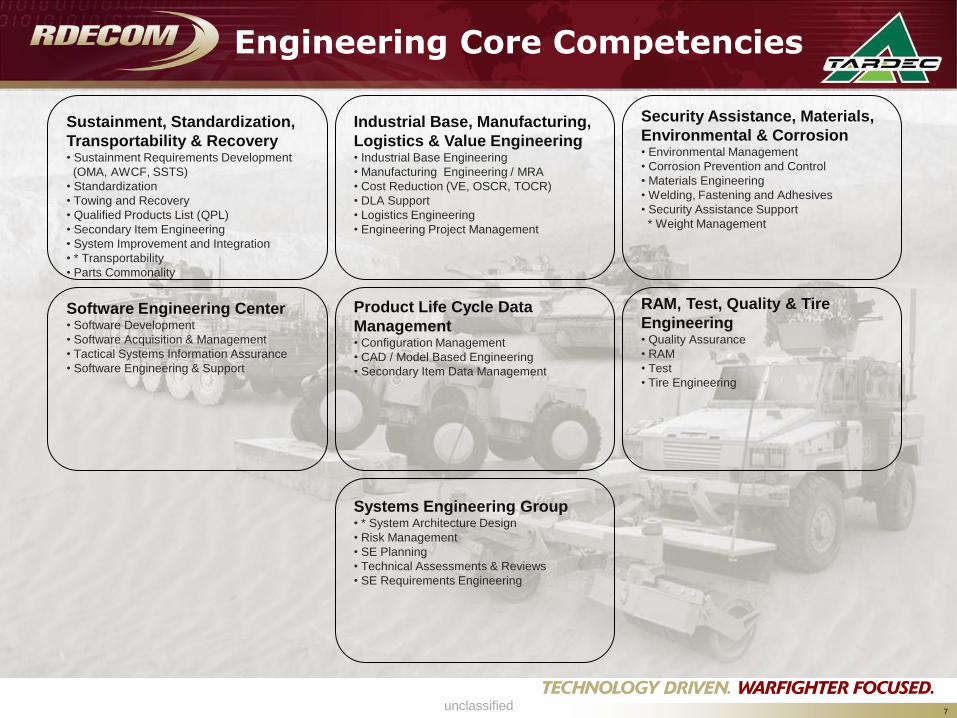
Engineering Core Competencies
7
Sustainment, Standardization,
Transportability & Recovery• Sustainment Requirements Development
(OMA, AWCF, SSTS)
• Standardization
• Towing and Recovery
• Qualified Products List (QPL)
• Secondary Item Engineering
• System Improvement and Integration
• * Transportability
• Parts Commonality
Industrial Base, Manufacturing,
Logistics & Value Engineering • Industrial Base Engineering
• Manufacturing Engineering / MRA
• Cost Reduction (VE, OSCR, TOCR)
• DLA Support
• Logistics Engineering
• Engineering Project Management
RAM, Test, Quality & Tire
Engineering• Quality Assurance
• RAM
• Test
• Tire Engineering
Software Engineering Center• Software Development
• Software Acquisition & Management
• Tactical Systems Information Assurance
• Software Engineering & Support
Product Life Cycle Data
Management• Configuration Management
• CAD / Model Based Engineering
• Secondary Item Data Management
Security Assistance, Materials,
Environmental & Corrosion• Environmental Management
• Corrosion Prevention and Control
• Materials Engineering
• Welding, Fastening and Adhesives
• Security Assistance Support
* Weight Management
Systems Engineering Group• * System Architecture Design
• Risk Management
• SE Planning
• Technical Assessments & Reviews
• SE Requirements Engineering
unclassified
unclassified
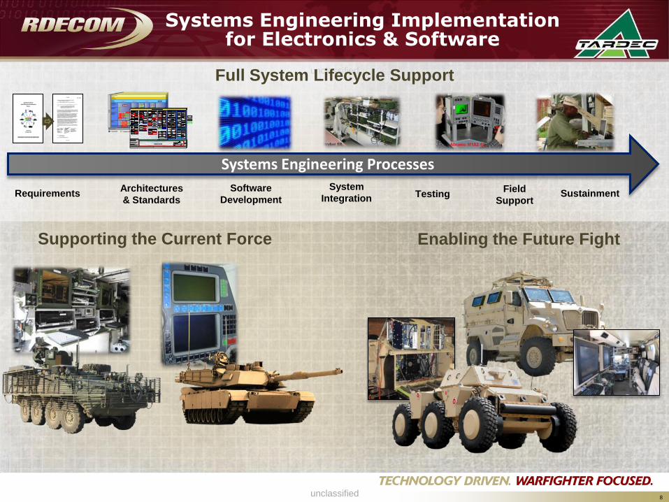
Systems Engineering Implementation for Electronics & Software
8
Systems Engineering Processes
Supporting the Current Force
Architectures
& Standards
Software
Development
System
IntegrationField
SupportRequirements Testing
Full System Lifecycle Support
Enabling the Future Fight
Sustainment
unclassified
unclassified
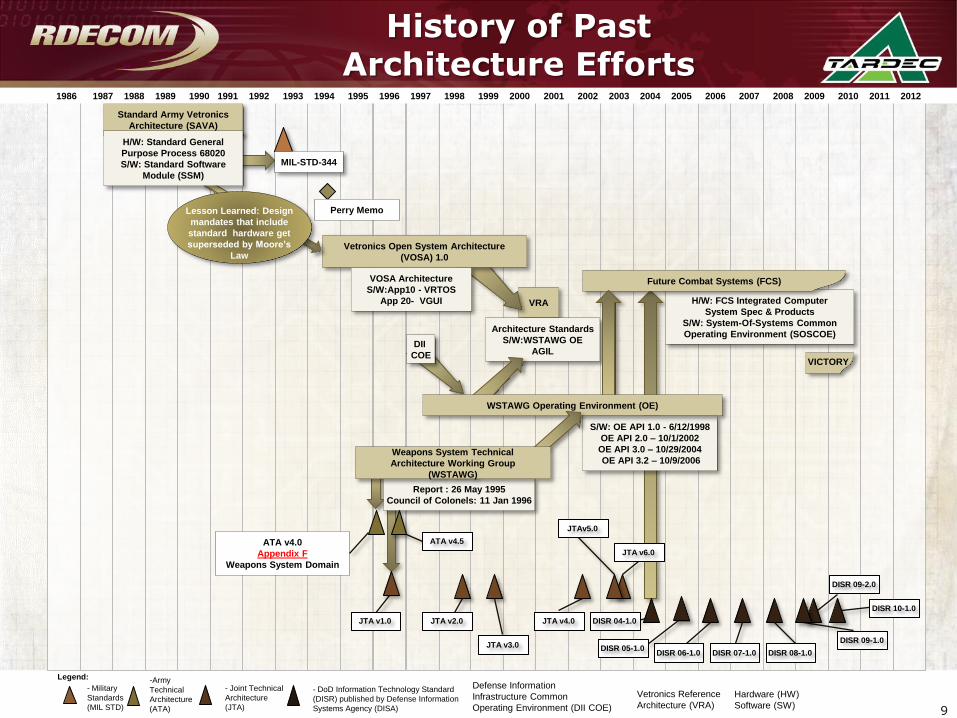
History of Past Architecture Efforts
VRA
Architecture Standards
S/W:WSTAWG OE
AGIL
Vetronics Open System Architecture
(VOSA) 1.0
Standard Army Vetronics
Architecture (SAVA)
- Military
Standards
(MIL STD)
VOSA Architecture
S/W:App10 - VRTOS
App 20- VGUI
Legend:
H/W: FCS Integrated Computer
System Spec & Products
S/W: System-Of-Systems Common
Operating Environment (SOSCOE)
Future Combat Systems (FCS)
DII
COE
Report : 26 May 1995
Council of Colonels: 11 Jan 1996
ATA v4.0
Appendix F
Weapons System Domain
S/W: OE API 1.0 - 6/12/1998
OE API 2.0 – 10/1/2002
OE API 3.0 – 10/29/2004
OE API 3.2 – 10/9/2006
-Army
Technical
Architecture
(ATA)
- Joint Technical
Architecture
(JTA)
- DoD Information Technology Standard
(DISR) published by Defense Information
Systems Agency (DISA)
Defense Information
Infrastructure Common
Operating Environment (DII COE)
Vetronics Reference
Architecture (VRA)
Hardware (HW)
Software (SW)
H/W: Standard General
Purpose Process 68020
S/W: Standard Software
Module (SSM)
VICTORY
DISR 06-1.0
WSTAWG Operating Environment (OE)
Lesson Learned: Design
mandates that include
standard hardware get
superseded by Moore’s
Law
Weapons System Technical
Architecture Working Group
(WSTAWG)
MIL-STD-344
DISR 07-1.0 DISR 08-1.0
DISR 09-1.0
DISR 09-2.0
DISR 04-1.0
JTA v6.0
JTAv5.0
JTA v4.0
JTA v3.0
JTA v2.0JTA v1.0
ATA v4.5
DISR 05-1.0
Perry Memo
1986 1987 1988 1989 1990 1991 1992 1993 1994 1995 1996 1997 1998 1999 2000 2001 2002 2003 2004 2005 2006 2007 2008 2009 2010 2011 2012
DISR 10-1.0
9
unclassified
unclassified
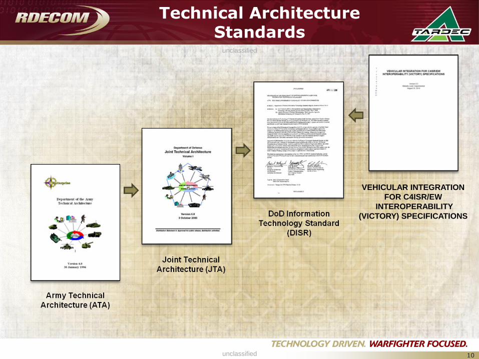
Technical Architecture Standards
10
VEHICULAR INTEGRATION
FOR C4ISR/EW
INTEROPERABILITY
(VICTORY) SPECIFICATIONS
unclassified
unclassified
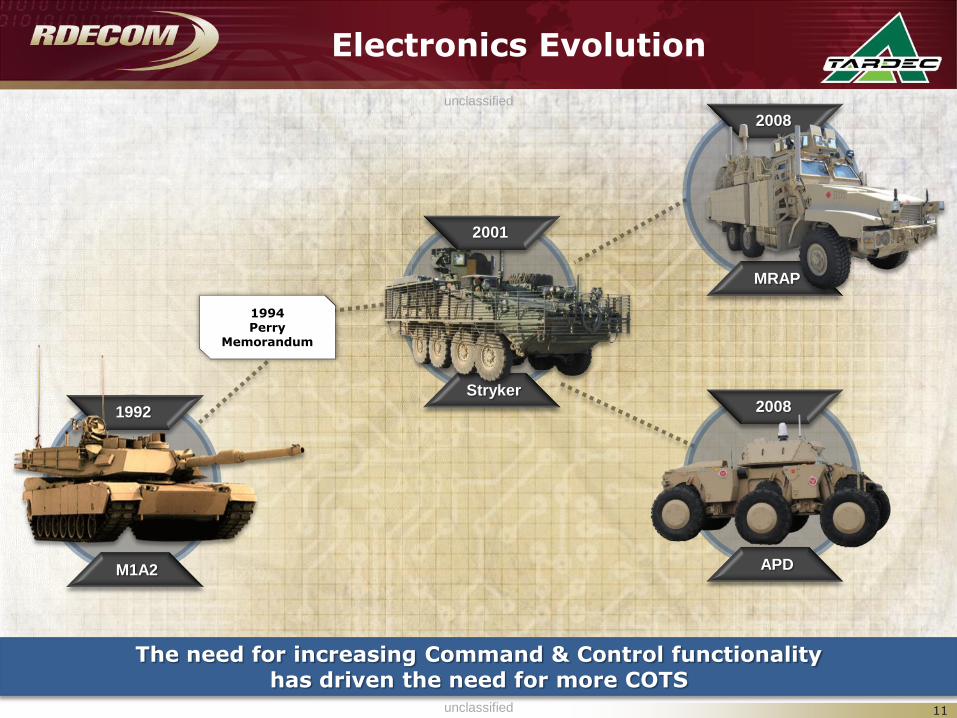
Electronics Evolution
M1A2
1992
APD
2008Stryker
MRAP
2008
1994 Perry
Memorandum
2001
11
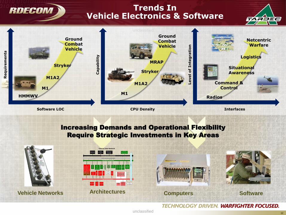
The need for increasing Command & Control functionality has driven the need for more COTS
unclassified
unclassified
Trends InVehicle Electronics & Software
12
Increasing Demands and Operational Flexibility
Require Strategic Investments in Key Areas
Vehicle Networks ComputersArchitectures Software
Software LOC
Req
uir
em
en
ts
Cap
ab
ilit
y
CPU Density Interfaces
Level
of
In
teg
rati
on
HMMWV
M1A2
Stryker
Ground Combat Vehicle
M1
M1A2
Stryker
M1
Ground Combat Vehicle
Command & Control
Situational Awareness
Logistics
Radios
NetcentricWarfare
MRAP
Vehicle Data Network
Data Network (Unclassified)
Data Network (Classified)
Cross
Domain
Guard
C
lassifie
d
Da
ta
Un
cla
ssifie
d
Da
ta
Opera
tor
Work
sta
tions
(Dis
pla
ys &
Contr
ols
)
with C
ross D
om
ain
Guard
to
allo
w m
ultip
le levels
of
cla
ssific
ation o
n the s
am
e
dis
pla
y
C
lassifie
d
Da
ta
C
lassifie
d D
ata
C
lassifie
d
Data
EPLRS SINCGARS
GPSBFT
Vehicle Control Bus (Unclassified)
Un
cla
ssifie
d
Da
ta
Vehicle Video Bus (Unclassified)
Slip
Rin
g
Engine and
Powerpack
Un
cla
ssifie
d
Da
ta
Un
cla
ssifie
d
Da
ta
Un
cla
ssifie
d
Da
ta
Un
cla
ssifie
d
Da
ta
Access Point
(IEEE 802.11) [Transmits
Diagnostic and Logistics
Data in Garrison]
360
Situation
Awareness
Cameras
Mast
Mounted
EO/IR
Sensors Po
we
r
Dis
trib
utio
n
Un
it
Un
cla
ssifie
d
Da
ta
Un
cla
ssifie
d
Da
ta
Mission
Data
Storage
FB
CB
2
Ad
va
nc
ed
Fie
ld
Art
ille
ry T
ac
tic
al
Da
ta S
ys
tem
(AF
AT
DS
)
Ma
ne
uv
er
Co
ntr
ol S
ys
tem
(MC
S)
All S
ou
rce
An
aly
sis
Sy
ste
m (
AS
AS
)
Mass
Memory
Storage
Single Point
Downloader
Ne
two
rke
d
I/O
Co
mp
utin
g
Un
cla
ssifie
d
Da
ta
Ve
hic
le C
on
tro
ls
Dia
gn
ostics a
nd
Pro
gn
ostics
Co
mm
on
Lo
g
Op
era
tio
na
l
En
viro
nm
en
t 2
(CL
OE
)
Power
Distribution
Unit
Ku-Band
SatCom
Only on
Reconnaissance
and Fire Support
Vehicles
Only on
Commander’s
Vehicles
Near Term
Digital Radio
(NTDR) or Joint
Tactical Radio
System (JTRS)
Digital Driver’s
Instrument
Panel (DIP)
Co
mm
an
de
r’s
Re
mo
te
FB
CB
2
Dis
pla
y
Cla
ssifie
d
Da
ta
Ro
ve
r
C
lassifie
d
Da
ta
Ine
rtia
l U
nit
Ne
two
rke
d
I/O
Co
mp
utin
g
Em
be
dd
ed
Tra
inin
gU
ncla
ssifie
d
Da
ta
Mis
sio
n
Re
he
rsa
l
C
lassifie
d
Da
ta
unclassified
unclassified
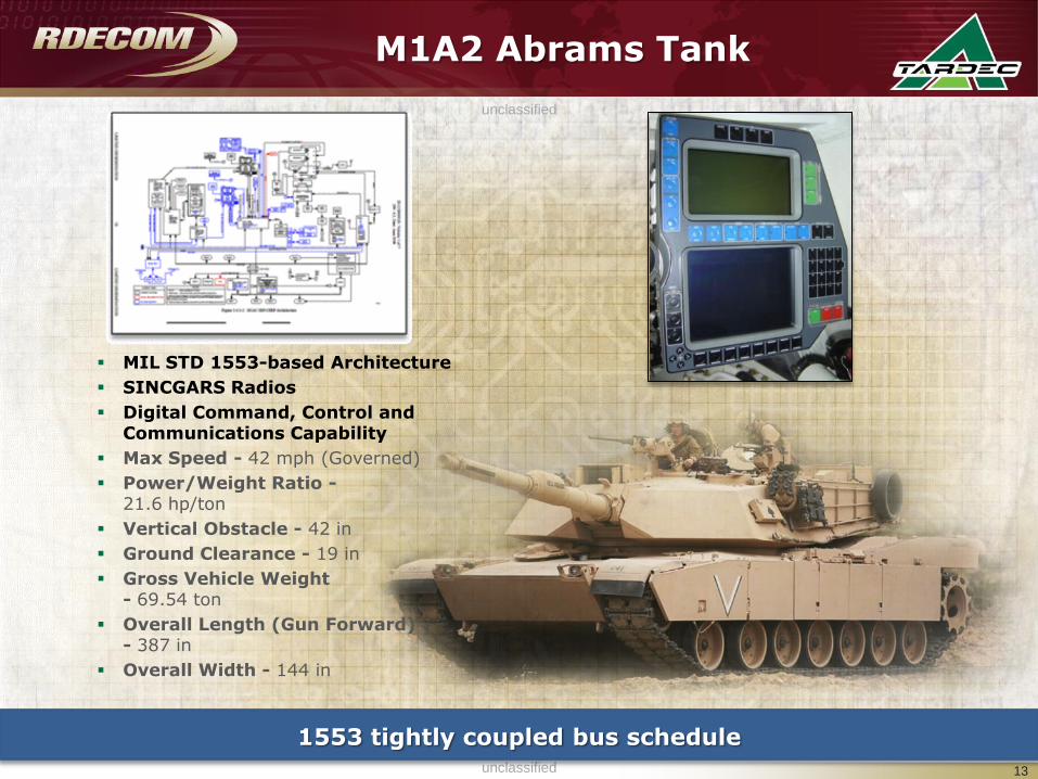
M1A2 Abrams Tank
MIL STD 1553-based Architecture
SINCGARS Radios
Digital Command, Control and Communications Capability
Max Speed - 42 mph (Governed)
Power/Weight Ratio -21.6 hp/ton
Vertical Obstacle - 42 in
Ground Clearance - 19 in
Gross Vehicle Weight - 69.54 ton
Overall Length (Gun Forward) - 387 in
Overall Width - 144 in
1553 tightly coupled bus schedule
13
unclassified
unclassified
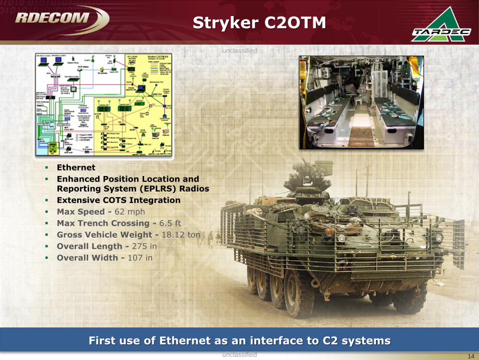
Stryker C2OTM
Ethernet
Enhanced Position Location and Reporting System (EPLRS) Radios
Extensive COTS Integration
Max Speed - 62 mph
Max Trench Crossing - 6.5 ft
Gross Vehicle Weight - 18.12 ton
Overall Length - 275 in
Overall Width - 107 in
First use of Ethernet as an interface to C2 systems
14
unclassified
unclassified
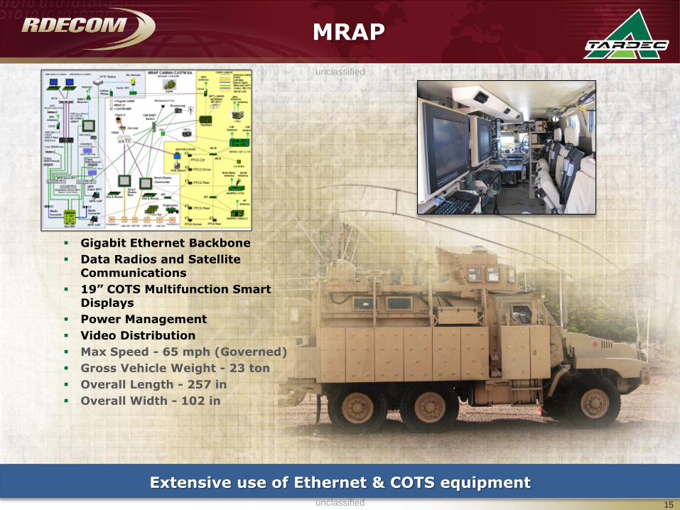
MRAP
Gigabit Ethernet Backbone
Data Radios and Satellite Communications
19” COTS Multifunction Smart Displays
Power Management
Video Distribution
Max Speed - 65 mph (Governed)
Gross Vehicle Weight - 23 ton
Overall Length - 257 in
Overall Width - 102 in
Extensive use of Ethernet & COTS equipment
15
MRAPMRAP
unclassified
unclassified
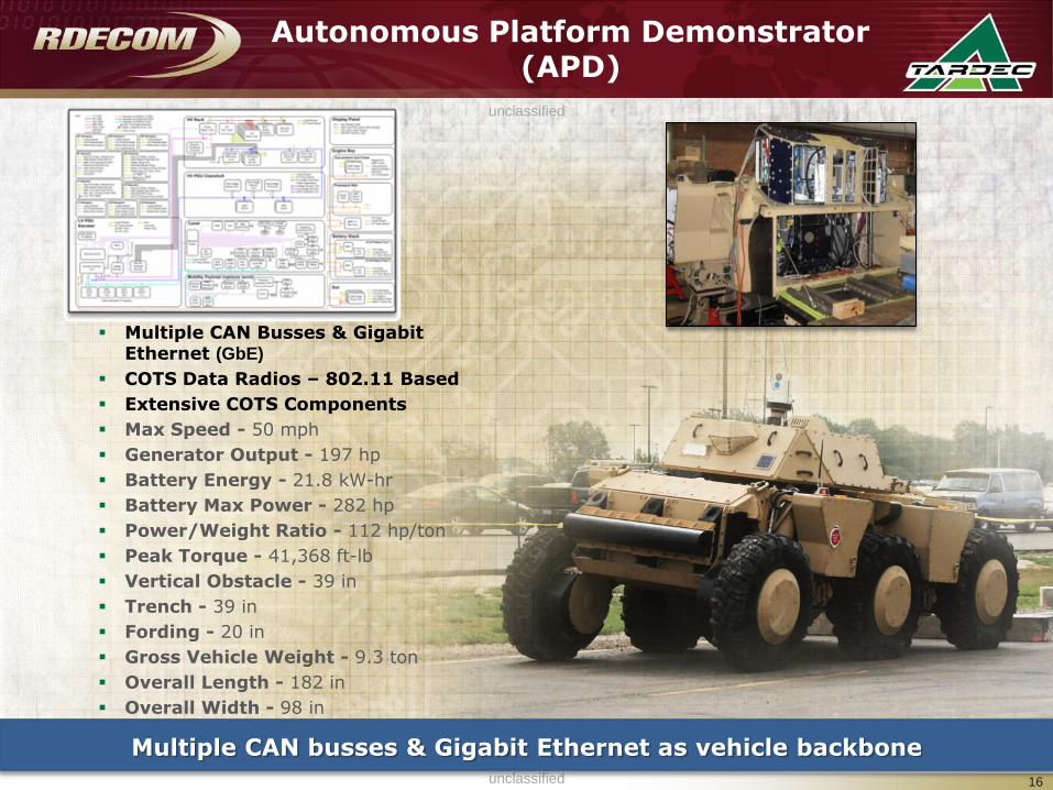
Autonomous Platform Demonstrator (APD)
Multiple CAN Busses & Gigabit Ethernet (GbE)
COTS Data Radios – 802.11 Based
Extensive COTS Components
Max Speed - 50 mph
Generator Output - 197 hp
Battery Energy - 21.8 kW-hr
Battery Max Power - 282 hp
Power/Weight Ratio - 112 hp/ton
Peak Torque - 41,368 ft-lb
Vertical Obstacle - 39 in
Trench - 39 in
Fording - 20 in
Gross Vehicle Weight - 9.3 ton
Overall Length - 182 in
Overall Width - 98 in
Multiple CAN busses & Gigabit Ethernet as vehicle backbone
16
unclassified
unclassified
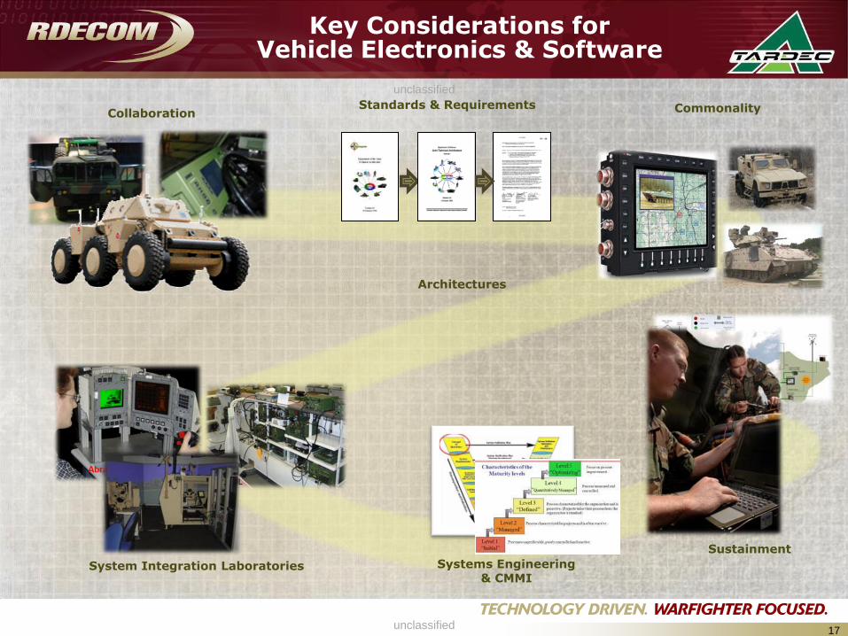
Key Considerations for Vehicle Electronics & Software
17
CommonalityCollaboration
Sustainment
Standards & Requirements
System Integration Laboratories Systems Engineering & CMMI
Architectures
unclassified
unclassified
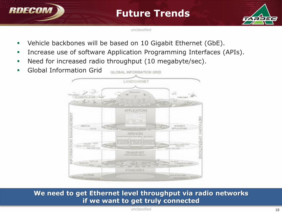
Future Trends
Vehicle backbones will be based on 10 Gigabit Ethernet (GbE).
Increase use of software Application Programming Interfaces (APIs).
Need for increased radio throughput (10 megabyte/sec).
Global Information Grid
18
We need to get Ethernet level throughput via radio networks if we want to get truly connected
unclassified
unclassified
unclassified
unclassified19
**Disclaimer: Reference herein to any
specific commercial company, product,
process, or service by trade name,
trademark, manufacturer, or otherwise,
does not necessarily constitute or imply its
endorsement, recommendation, or favoring
by the United States Government or the
Department of the Army (DoA). The
opinions of the authors expressed herein
do not necessarily state or reflect those of
the United States Government or the DoA,
and shall not be used for advertising or
product endorsement purposes.**
unclassified
unclassified
BACK UP
20

unclassified
unclassified
Description• Leverages RDECOM and DoD capabilities in a repeatable process to apply rigorous systems
engineering to ground systems integration
• Provides customer partners a single entry point for cost, schedule, performance and risk
management of system integration projects
Modeling
Physical Simulation
C4 Integration Bench
GVIC Projects :
• MRAP Capability Insertion
• C2OTM* – MRAP
• C2OTM* – Stryker
• LAV-R Upgrade
• RS-JPO
MRAP Capability Insertion• Vanguard (ARDEC)
—CROWS II RWS (ARDEC)
—Boomerang (ARDEC)
—Double Shot (ARDEC)
• OGPK Overhead Protection (ARDEC
effort)
• LRAS3
• Check 6 Camera
• Overhead Wire Mitigation
• IBIS TEK Lights
• RPG Protection
• Power Upgrade (derived requirement)
• C4I Architecture (derived requirement)
• Thrown Object Protection SystemUser Jury
*Command & Control On The Move
Employs TARDEC organic Concepts, Analysis, Systems Simulation
and Integration (CASSI), System Engineering (SE), Prototype
Integration Facility and significant contributions from other RDECs
and Organizations
Accomplishments• Accelerated Remote Weapon Station Integration with ARDEC for the Caiman,
MaxxPro and RG-33 systems
• Completed Full Capability Insertion Integration for Caiman Systems
Ground Vehicle Integration Center
Electronics Integration
21
RWS System Integration
unclassified
unclassified
DB Overview –What is Digital Backbone
22
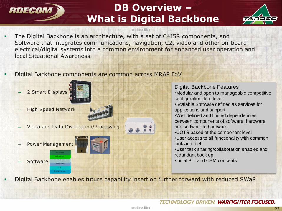
The Digital Backbone is an architecture, with a set of C4ISR components, and Software that integrates communications, navigation, C2, video and other on-board electrical/digital systems into a common environment for enhanced user operation and local Situational Awareness.
Digital Backbone components are common across MRAP FoV
– 2 Smart Displays
– High Speed Network
– Video and Data Distribution/Processing
– Power Management
– Software
Digital Backbone enables future capability insertion further forward with reduced SWaP
External Interfaces
OS
OS Abstraction
Interface Services
WMI Services
Presentation
Digital Backbone Features•Modular and open to manageable competitive
configuration item level
•Scalable Software defined as services for
applications and support
•Well defined and limited dependencies
between components of software, hardware,
and software to hardware
•COTS based at the component level
•User access to all functionality with common
look and feel
•User task sharing/collaboration enabled and
redundant back up
•Initial BIT and CBM concepts
unclassified
unclassified
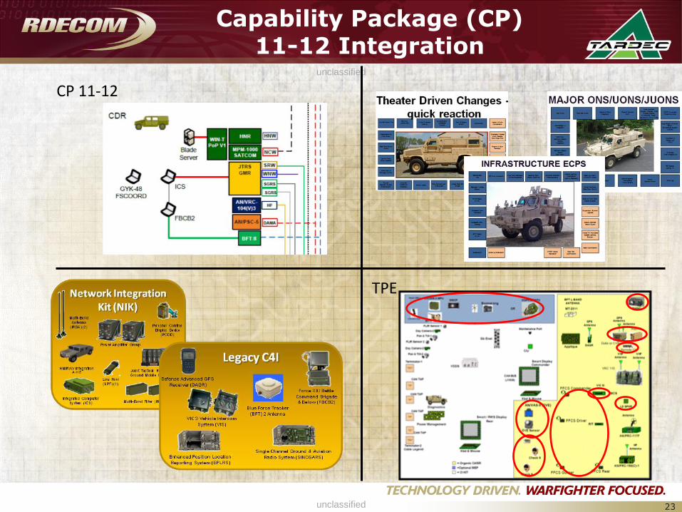
Capability Package (CP) 11-12 Integration
23
CP 11-12
TPE