combination afcis: what they will and will … circuit breakers, both types provide both overcurrent...
TRANSCRIPT
Copyright © 2012 IEEE
(Presented at the 19th Annual IEEE IAS Electrical Safety Workshop, Daytona Beach, Jan/Feb 2012)
This material is posted here with permission of the IEEE. Internal or personal use of this material is permitted. However, permission to reprint/republish this material for advertising or promotional purposes or for creating new collective works for resale or redistribution must be obtained from the IEEE by writing to [email protected]. By choosing to view this document, you agree to all provisions of the copyright laws protecting it.
COMBINATION AFCIs:
WHAT THEY WILL AND WILL NOT DO
Copyright Material IEEE
Paper No. ESW-XX (do not insert number)
Joseph C Engel, PhD Member, IEEE 107 Overlook Circle Monroeville PA 15146 USA [email protected]
Abstract – All new home branch circuits are required by Code to be electronically protected, either by Ground Fault Circuit Interrupters (GFCIs) or Arc Fault Circuit Interrupters (AFCIs). Areas including kitchens, bathrooms, garages, etc. must be protected by GFCIs, while living areas must be protected by AFCIs. The AFCI is the fourth generation in residential branch circuit protection after fuses, circuit breakers, and GFCIs.
National Electrical Code in 2002 first added AFCI protection, for bedrooms outlets. In 2008, coverage was expanded to all living areas, also adding that only “Combination AFCIs” are allowed.
Manufacturers and UL claim that arcing across a break in a cord’s conductor is hazardous, and that a Combination AFCI will respond to prevent a fire. The author believes the claim is unproven, and will explain why the disallowed Branch/feeder AFCI provides more protection at less cost.
Index Terms — home, electrical safety, ground fault protection, parallel arc, series arc, arc fault circuit interrupter, Branch/feeder AFCI Combination AFCI, CPSC, NEC, UL, NEMA
I. INTRODUCTION
From 2002 to 2008, manufacturers met the requirement that new home bedrooms be protected with AFCIs by supplying circuit breaker devices that UL calls a Branch/feeder AFCI. These devices provide all the protection of a normal residential miniature circuit breaker, as well as sensitive protection for a parallel arcing fault. While not a UL requirement, every Branch/feeder AFCI manufactured during this period also contained 30mA ground fault protection.
As mentioned, since 2008 the NEC Code disallows the use of a Branch/feeder AFCI, allowing only a Combination type AFCI. The author believes the performance features of this device are poorly understood. Some think, erroneously, that the Combination device includes arc fault plus ground fault protection. While the Branch/feeder provides ground fault protection, some Combination devices do not. Others believe, again erroneously, that the Combination adds series arc protection of appliance cords. There is no such test for it in UL1699, the UL Standard for AFCI.
A Google search for words {series, arcing, cord, "Combination AFCI"} yields 4500 hits. Clearly most people unfortunately associate series arc protection of cords with the Combination AFCI. The author believes the confusion may come from the four AFCI manufacturers [1],[2],[3],[4], NEMA their trade organization [5], and UL [6] all claiming that a Combination AFCI adds protection against series arcing in cords.
Manufacturer X’s web reference states:
Do Not Confuse "Combination AFCI" with "AFCI/GFCI"
“One area of potential confusion is with the use of the term "combination" as associated with AFCIs. A "combination" AFCI is one that combines the protection for parallel and series arcing into a single device as described above.”
So while the Branch/feeder provides an important but
unadvertised feature of 30mA ground fault, the UL Listed Combination AFCIs claim a feature that is not supported by the associated UL1699 Standard, and is thus unproven.
Manufacturer X provides a simple definition of a series arcing event [7]:
“A series arc is an arcing incident across a break in a conductor. A common example is a cut across one of the two wires in a lamp cord, with a dangerous arc forming in the gap. Combination AFCI circuit breakers detect the arcing condition and turn off the circuit, thus providing the enhanced protection.”
The author created the described condition in his shop, and tested all commercial Combination AFCIs; none tripped and turned off the circuit. Further, the author used cotton to verify if the arc was a fire hazard. The author could not ignite the cotton. He repeated these tests with a two-conductor heater core carrying 15A with the same results.
The preceding explains the author’s purpose for writing this
paper: Combination AFCIs do not perform as advertised. Also the requirement in NEC 2008 that only Combination AFCIs are allowed is a mistake that the author believes will cost lives.
Today there are two types of AFCIs available; the Branch/feeder and the Combination. Their technical performance differences will be described to allow manufacturers, UL, and others to evaluate their support for the Combination AFCI. The author hopes to get industry backing for a proposed revision for NEC 2014 that will remove the mandate that a Combination AFCI be used.
Following a review of the performance features of today’s AFCIs and the author’s proposal for NEC 2014, the bulk of this paper will discuss the history of the AFCI, in the hope that the standard and code-making processes can be improved.
It is important that the reader not misinterpret the author’s objectives. They are not to challenge the value of AFCI technology, or its importance in reducing home fires and thus loss of property and life. The values are recognized. He just wants to put pressure on those organizations that control the codes and standard process to encourage their staffs, especially the technical team members, to make a sincere effort to understand and accurately communicate on the technical issues.
There is still an important role for IEEE engineers and others in the electrical safety business; they need to insure that their voices are heard.
II. PERFORMANCE FEATURES OF TODAY’S AFCIs
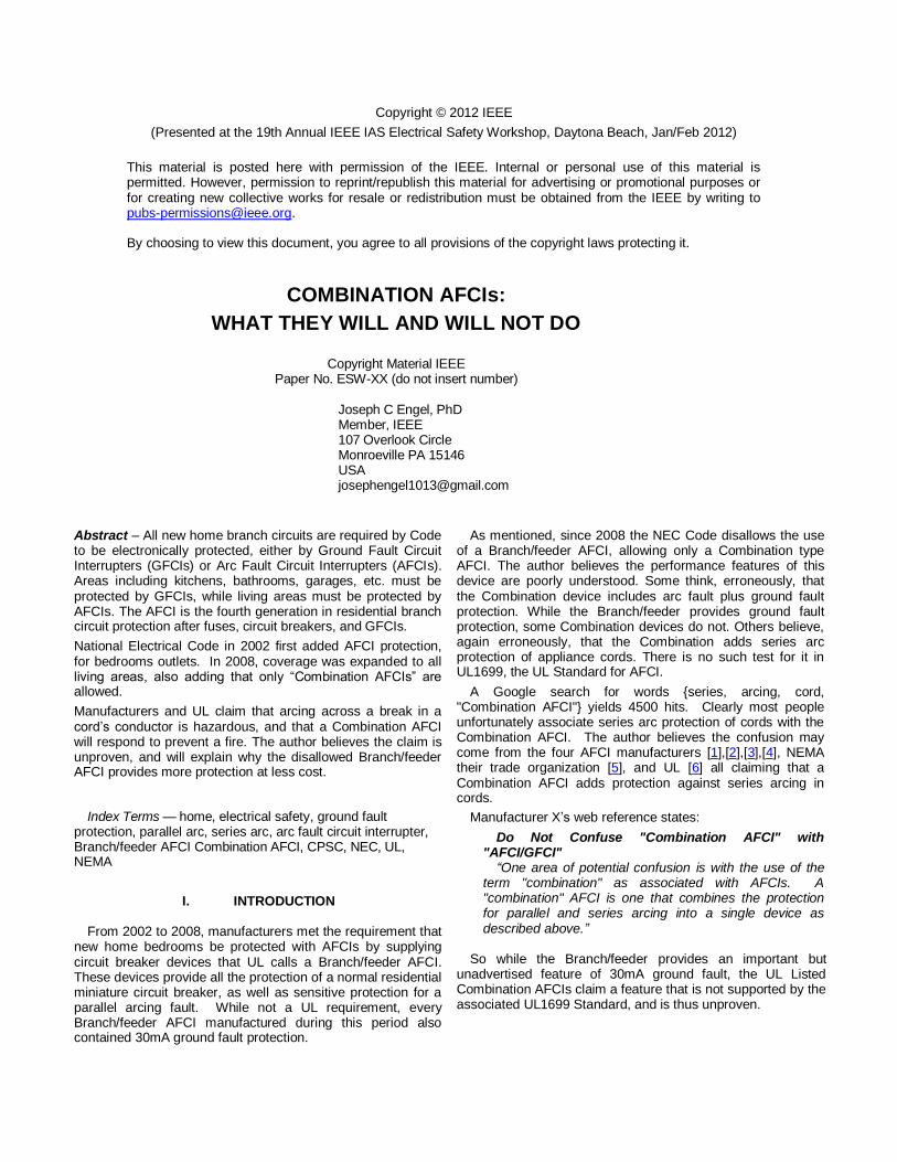
The following Table shows the actual and claimed features of today’s AFCI. There are only two types, both are circuit breakers. The Branch/feeder was first introduced in 2002; it is still available today and represents the bulk of the installed base. Manufacturers were forced to introduce the more expensive, and less capable, Combination AFCI in 2008 as the result of a mandate in NEC 2008.
types of protection Branch/feeder AFCI Combination AFCI
overcurrent yes yes
overload yes yes
ground fault (30mA) yes no*
parallel arcing yes yes
series arcing no no
* All 1
st generation designs had GFCI, newer generations
don’t.
Table 1: AFCI Performance Differences Being circuit breakers, both types provide both overcurrent
and overload protection. All Branch/feeder AFCIs provide ground fault (30mA) protection, while manufacturers are removing this feature from their Combination AFCIs. Both AFCIs provide protection against parallel arcing, while neither provides protection against series arcing. The UL 1699 AFCI standard only tests for parallel arcing; it doesn’t test for ground fault or series arcing.
The importance of ground fault goes beyond shock protection; it in combination with arc fault protection has been shown by UL to mitigate the effects of a “glowing contact”.
Looking at Table 1 it is hard to understand why Combination AFCI manufacturers and UL claim that a Combination AFCI protects against series arcing. Since there is no test for it in UL 1699, the claim is unproven. Further it is hard to understand why NEC 2008 disallows the proven Branch/feeder in favor of the Combination that provides less protection at higher cost. The AFCI history to be presented may provide an understanding. It will not however be able to justify making unproven performance claims or the NEC mandate.
III. PROPOSED REVISION FOR 2014 NATIONAL ELECTRICAL CODE (NFPA 70)
The author hopes the readers of this paper will support his
three simple NEC code proposals, see section XXI. The first is shown below. The second adds a 30mA ground fault requirement; the third eliminates wording allowing AFCI protection to be “located at the first receptacle outlet”. 210.12 Are-Fault Circuit-Interrupter Protection. (B) Dwelling Units: All 125-volt, single-phase, 15- and 20- ampere branch circuits supplying outlets installed in dwelling unit family rooms, dining rooms, living rooms, parlors, libraries, dens, bedrooms, sunrooms, recreation rooms, closets, hallways, or similar rooms or areas shall be protected by a listed arc-fault circuit interrupter, combination-type, installed to provide protection of the branch circuit.
This simple Code edit can save American home builders more than $200M a year, while also saving lives. The following will support these claims.

IV. HISTORY
This paper outlines the history of the AFCI circuit breaker development from the earliest recognition of a new home wiring hazard, to today's NEC requirement that the branch circuits protecting living areas be protected by such a device. The role played by the four principal participants will be described: U. S. Consumer Product Safety Commission (CPSC), Underwriters Laboratories Inc. (UL), National Electrical Manufacturers Association (NEMA), and National Electrical Code Committee (NEC) Code Panel No. 2.
The author participated in a hands-on manner in the development of AFCI technology at every step of the way:
early testing to understand the nature of the new problem,
design and testing of a product that could mitigate the problem,
participating as a NEMA Task Force member in the development of the AFCI standard UL1699,
and finally making presentations to NEC Code Panel No. 2 during the 1999, 2005, and 2008 cycles.
The author believes that all who worked in this process did so honestly, with the goal of improving home electrical safety. Even so, the technical issues involved may have been misunderstood, with the result that the promotional information associated with the Combination AFCI circuit breaker is inaccurate. He hopes that the AFCI stakeholders will review the issues, make appropriate corrections, and most importantly support the suggested revisions to the Code. The revision will allow the use of the Branch/feeder AFCI.
V. THE PROBLEM
Today’s AFCI technology originated during the early 1990s, when appliance manufacturers became concerned over home fires caused by damage to their power cords. They felt that if the circuit breakers protecting the cord were more sensitive and responded faster, there would be fewer cord-related fires.
Eventually CPSC, the guardian of consumer home safety, became involved. The CPSC funded several UL studies involving home electrical safety with emphasis on short-circuit protection of cords. This emphasis came from a review of the field fire information provided to CPSC. It showed that high current parallel arcing faults, due to insulation failures of the cord, were the probable cause of many fires. A typical example from CPSC’s data base:
Incident Date: 19831226 City: State: PA THREE CHILDREN DIED AS A RESULT OF A FIRE IN A THREE BEDROOM HOUSE. A FIRE OFFICIAL INTERVIEWED STATED
THAT IT WAS DETERMINED THAT THE ELECTRICAL CIRCUITS IN THE HOUSE WERE OVERLOADED WITH MULTIPLE APPLIANCES PLUGGED INTO MULTIPLE EXTENSION CORDS THAT EITHER AN
APPLIANCE CORD OR EXTENSION CORD IGNITED, CAUSING THE FIRE.
The installation on an overheated cord can melt permitting conductor-to-conductor contact and a resulting arcing fault.
It is also possible to develop arcing parallel fault due to mechanical damage to the cord’s insulation. Again from CPSC data base:
Incident Date: 20000418 City: BETHLEHEM State: PA AN ELECTRIC CROCK POT BEING USED TO COOK FOOD
CAUGHT FIRE WHEN THE APPLIANCE CORD BECAME CRIMPED BETWEEN THE OUTSIDE METAL PAN AND THE INTERIOR CERAMIC CROCK OF THE UNIT. NO INJURIES RESULTED BUT
THE HOME SUSTAINED $150,000 IN DAMAGE.
These are two examples of the general types of cord-related faults, see Fig. 1.
Fig. 1. Typical Cord Arcing Fault
Residential miniature breakers provide both overload (too many toasters) and overcurrent (short-circuit) protection. The overload protection includes a thermal time delay, via a bimetal member, while the overcurrent protection has no intentional delay. It is referred to as “instantaneous” trip protection.
IV. WHY DIDN’T THE BREAKER TRIP? In the first case, an overheated cord, the breaker is by Code
capable of protecting its typical 12 or 14AWG branch wiring, which ends at the outlet. The circuit breaker cannot know that an extension cord (typically 16AWG or even 18AWG) is plugged into a receptacle on the branch. So a circuit breaker cannot protect a cord from overload. Once the insulation melted, and the conductors touched, one would think that the circuit breaker’s instantaneous trip function would immediately respond to de-energize the circuit, but it apparently didn’t.
In the second case, mechanical force damaged the cord’s insulation and again allowed the two conductors to touch. Again, once the wires touched one would think that the circuit breaker’s instantaneous trip would function, but it apparently didn’t.
So were the breakers defective? In both cases they are not required, per the UL489 Standard that covers these miniature circuit breakers, to trip under a condition when two conductors touch. When tested, the author was personally surprised that a miniature circuit breaker would not respond to this condition. The arcing that develops can be dramatic. Those who have seen such a test are usually astonished that the breaker didn’t trip.
So the makers of miniature circuit breakers were confronted with a serious problem. While their product performed as required by their Standard, it did not perform as expected. Further, its failure to respond apparently can result in missed opportunities to prevent fires and save lives.
Miniature circuit breakers that meet the requirements of UL489 are remarkable, affordable, devices and provide significant circuit protection. They provide a convenient manual disconnect means, accurate overload protection, and via an instantaneous trip feature short-circuit protection.

A “short-circuit” is sometimes referred to as a “bolted” fault. So rather than two conductors at different potentials merely touching, they would be bolted together and cannot arc. For this test, the circuit breaker would be connected to a 120 VAC source. The resistance of a conductor connected to the output of the breaker would establish the available fault current.
For example, a miniature breaker with the typical maximum short-circuit rating of 10,000A would use a length of wire corresponding to 120/10,000, or 12 milliohms. When tested the actual short-circuit will typically be more like 5000A due to the resistance within the breaker, as well as the arc voltage that develops as the breaker contacts open.
While there is a test for the maximum short-circuit rating, there is no test for a minimum short-circuit rating. In other words, how high of a short-circuit current is required for a miniature circuit breaker to trip instantaneously. Testing showed that minimum short-circuit trip levels are too high, and response time too slow, for a circuit breaker to reliably respond in time to terminate the dangerous sporadic arcing when two conductors touch. Thus began the development of what today is called an arc fault circuit interrupter (AFCI).
When miniature breakers were tested, it was found that the minimum instantaneous trip current level ranged from 200 to 500A RMS. This corresponds to peak values from about 300 to 700A. At these values, approximately two full line cycles (four ½ cycles) were required for the breaker to trip.
V. AVAILABLE SHORT-CIRCUIT CURRENT Now that the instantaneous trip level was determined, the
next question was, “What is the range of available short-circuit currents available at residential electrical outlets?” In 1993 the Electronics Industries Association (EIA) initiated a fact-finding study with UL to determine the available fault current for residential receptacles. Eighty residences throughout the US were surveyed.
The distribution of the estimated short-circuit currents for 15 ampere branch circuits is shown in Fig. 2. Curve A shows the available short-circuit current available at the receptacle itself, while curve B assumes the short would occur in a six-foot appliance cord. One key data point is the 100% percentile value of 75A: all 1590 receptacles in the 80 homes could supply a short-circuit current of 75A RMS or greater. This value is surprisingly low, and, as will be demonstrated, is the cause of the problem. A second key point is the 50%, or median value, of 255A. Half of the receptacles had an available short-circuit current of less than 255A, again surprisingly low.
When the average instantaneous trip level value of miniature circuit breakers (~350A) is compared to the expected available value (255A), one concludes that the instantaneous trip feature is of limited value in preventing fires. The breaker’s thermal overload will trip under this short-circuit condition, so the failure of the instantaneous trip circuit to respond is not inherently a safety issue.
It’s interesting that larger homes have a larger problem, the result of their longer branch circuit cable runs.
Fig. 2. Available Short-Circuit Current
VI. WHAT HAPPENS WHEN WIRES TOUCH? The preceding discussed short-circuit test conditions;
currents during these tests are continuous sinusoidal waves. The fault voltage was zero, and thus power and energy dissipation at the fault is also near zero. There is no fire hazard.
The conditions when the two conductors of a cord come in contact, as the result of cord overheating or insulation damage, are significantly different. In this case the wires, once they make contact, can move apart by normal magnetic forces. The typical fault current and voltage for such an event, shown in Fig. 3, are quite different. For this test the available short-circuit current was set at the UL established minimum value of 75A RMS. This would yield a bolted fault peak current of ~106A.
Fig. 3. Arcing Current and Voltage Waveforms
A few comments on waveforms: 1. The current consists of a random, chaotic, series of
pulses.
2. Each pulse is slightly less than a full ½ cycle.
3. The typical peak current is ~80A, not 106A.
4. The reason for the reduced current peak can be seen
by looking at the arc voltage waveform.
5. The typical arc voltage of ~50V opposes the peak line
voltage of 170V, resulting in an effective peak source
voltage of only 120V.
6. Peak arc power is 80A x 50V = 4KW.
7. Energy per current pulse is ~20J, while the energy over
the 350mS of arcing shown is ~350J.
8. The RMS current value is only 45A, not 75A.
9. The time-to-trip of a 20A miniature circuit breaker at
45A ranges from 10 to 100S, too slow to respond to this
arcing condition.
So a standard residential miniature circuit breaker will not
respond to all hazardous high energy arcing fault conditions
caused by a cord insulation failure. As explained, the
breaker’s instantaneous trip function is too insensitive and the
thermal trip function is too slow.
VII. LOW INSTANTANEOUS TRIP (LIT) The EIA proposed a simple solution: merely lower the circuit
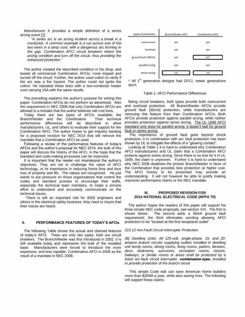
breaker’s instantaneous trip level to, say, 50A. The problem with this approach is that many household electrical appliances have normal inrush currents greater than 50A, including a bank of incandescent lamps and appliances with input transformers or large power supply filter capacitors. Another common condition that could cause an LIT breaker to trip is the burn out of an incandescent lamp. Often when a lamp burns out an arc is formed across the filament supporting structure. The resulting current bypasses the filament and is limited only by the branch circuit’s wire resistance and a fuse in the lamp base. The fuse is designed to limit current to no more than two ½ cycles, see Fig. 4.
Fig. 4. Lamp Burnout Arcing Event
While EIA, UL, and CPSC saw the positive advantages of LIT, the NEMA manufacturers knew it was impractical because of nuisance tripping concerns. An impasse existed; a better solution was needed.
VIII. STUDY OF THE CAUSES OF HOME ELECTRICAL FIRES
While the industry struggled with a newly recognized home
hazard, fires caused by arcing resulting from a cord’s insulation failure, CPSC funded UL to look at the broader issue of home electrical fires. The result of this UL study was a report [8] that not only outlined probable causes of electrical fires but also technology that might mitigate them. The design of this study was unique and showed the value of an independent federally funded organization like CPSC. Unlike publications by UL and NEMA manufacturers, CPSC publications are not restricted and protected by copyrights, reflecting their primary mission: to improve home safety.
An announcement letter was sent December 12th 1994 to 800 domestic and foreign companies. A condensed version of the letter, published as Appendix B in the report, is shown below.
------------------------------------------------------------
“UL/CPSC work to reduce residential electrical fires
You could be a part of this important work” “UL was recently awarded a contract from the U.S.
Consumer Product Safety Commission (CPSC) to research technology for detecting and monitoring conditions that could cause electrical wiring system fires. The purpose of- this project is to reduce the rates of death, injury and property loss from residential fires associated with electrical wiring systems. The study will center on devices and systems that can be used to decrease the likelihood of fires in older homes where the frequency of electrical system fires appears to be disproportionately high.
During the one-year project, UL will conduct an in-depth study of the practical technologies that might have the ability to detect and monitor precursory electrical conditions that could lead to fires in older residential wiring systems. This will be accomplished by conducting a comprehensive review of litera-ture on devices and systems of this type; by surveying industry organizations and manufacturers for new products and systems that could decrease the fire potential; and by acquiring and analyzing the most promising devices to determine ease and cost of installation, effectiveness, and possible problems that might be associated with their installation and use.
And this is where you could help. If you have developed or are developing a new product that might be used to detect or monitor problems in electrical wiring systems and would like the opportunity to have your technology considered in this project, we would like to hear from you. To help us protect your proprietary information, contact us before you send your product or product description. Call either Pete Baden in Northbrook, III., at (708) 272-8800, ext. 42011, or Richard Wagner in Melville, N.Y., (516) 271-6200, ext. 22275, before Jan. 31, 1995. Your participation in this project could help the CPSC and UL in their efforts to reduce property damage, injuries and deaths associated with residential electrical system fires.”
------------------------------------------------------------

The study involved the proposed investigation and testing of various home wiring faults that could result in a deadly home fire. UL solicited any person or organization to submit, for use in their testing program, any potential new product that might mitigate one or more of the identified hazards. A total of 11 product concepts were submitted to UL. Three of these were from today’s AFCI circuit breaker manufacturers.
The test reporting was “blind”. Each product was assigned a number, submitters were only told their number. Final reporting used these numbers to publish product descriptions as well as test results. The tests performed on each product were based on UL’s understanding of the product’s technology. Products 1, 2, and 3 were submitted as circuit breakers. Product 3 was the author’s design. The report described the three designs as follows:
Product No. 1 is an arc-fault detector that requires a minimum of approximately 100 mA of arcing current to function. To avoid unwanted tripping, a delay is used from the time of first recognition of the arcing signature until the time of interruption, and interruption only occurs if the signature persists. The arc-detection feature operates above and below the handle rating of the included 15 A overcurrent device. The version submitted for testing under this contract was an arc-fault detection circuit breaker mounted in a box with a cord and plug, and a receptacle for convenience in testing. Product No. 2 is an arc-fault detector that requires a minimum of approximately 3 A for it to function. It is intended to operate above and below the handle rating of the included 20 A overcurrent device. The device is packaged for installation in the service panel in conjunction with the included overcurrent device.
Product No. 3 is an arc-fault detector that is part of a branch-circuit overcurrent protective device rated 20 A. In order to avoid unwanted tripping in response to normal operational arcing at normal load currents, the product contains a direct arc detection feature which is intended to operate only when the current is above the handle rating of the overcurrent device. Product No. 3 also incorporates ground-fault interrupting technology as described below.
The tests performed and results, reported as pass/fail, are
shown in Table 1. PRODUCT
TEST 1 2 3
1 Point Contact Arc (290A) P P P
2 Damped-Motion Contact Arc (300/100A) F P P
3 Carbonized-Path Arc Fault F F P
4 Partial Carbonized Path Arc Fault F F P
5 Rotational Flexing
6 Wet-Track Arc Fault F F
7 Arc-Simulator Number 1 P F
8 Arc-Simulator Number 2 F F P
9 Series Make/Break Contact Arc: Loose Terminal F F
10 Series Make/Break Contact Arc: Broken Wire F F
11 Overheating Conductor: Glowing Contact F F
12 Operation Inhibit F F
13 Unwanted Tripping F F Table 1: Test Results
Product 1 failed all but one test, Product 2 failed all but two tests. In contrast Product 3 passed all conducted arcing tests but failed one of the unwanted (nuisance) tripping tests.
The table uses the term “series arc”. This term, and the term “parallel arc”, are defined by UL in the report.
Parallel Arcing Fault – See across-the-line arcing fault.
Across-the-Line-Fault – An insulation fault between an ungrounded circuit conductor and either a 1) grounded circuit conductor, or another ungrounded circuit conductor. Also referred to as parallel fault.
Series Arcing Fault – A series fault where arcing occurs.
Series (Continuity) Fault – A partial or total local failure in the intended continuity of a conductor characterized by either infinite resistance (a completely severed conductor) or by resistance that alternates between infinite resistance and high or normal resistance such as intermittent connection at a loose wiring terminal or splice.
Some of the tests UL developed duplicate actual home wiring faults, others don’t. The actual “real world” fault tests are listed below.
Test 1: Point Contact Arc (290A)
A utility blade was used to cut through a cord’s insulation, creating a parallel arcing fault. An available short-circuit value of 290A is used. This test addressed the appliance cord hazard, see III. THE PROBLEM.
Test 2: Damped-Motion Contact Arc (300/100A)
A parallel arcing fault is created by slowly bringing the exposed conductors at the end of a cord together. Available short-circuit values of 300 and 100A were used. This test also addressed the appliance cord hazard.
Test 9: Series Make/Break Contact Arc: Loose Terminal
The test created a series arcing event at an electrical terminal, with a 15A resistive load, by jiggling the loose connection. Products 1 and 2 were tested and failed. No fire indictor was used.
Test 10: Series Make/Break Contact Arc: Broken Wire
The test involved a break in one conductor of a two conductor cord. A series arcing event was created by jiggling the broken connection. Load currents of 3, 10, and 15A were used. Products 1 and 2 were tested and failed. No fire indictor was used.
Test 11: Overheating Conductor: Glowing Contact
The author believes that UL’s description of the “Glowing Contact” test in this report is the first time that UL acknowledged that such a home hazard exists. The ease with

which the hazard can be created indicates that such hazards exist in house wiring, and thus probably contribute to fires that result in property and life loss.
The test is disturbingly simple to perform, thus adding support to the claim that glowing contacts are a serious home wiring hazard. A length of AWG 14 solid copper wire is looped around a wire-binding screw of an electrical receptacle. The screw was not tightened, so the loop was loose. A 15A resistive load was plugged into the receptacle. The loop was then manipulated so that loop-screw connection could be jiggled to create a make/break arcing action. The arcing was not continuous, but rather more a series of sparks. After typically a minute of jiggling, the loop will adhere to the screw, at which time the jiggling is terminated. In about 30 seconds the connection will begin to glow the color of a toaster’s coil; thus the name.
Products 1 and 2 were tested and failed to trip during glowing connection formation.
Test 12: Operation Inhibit
Apparently UL determined that the arc detection schemes of both Products 1 and 2 utilized the high frequency content of the current waveform. A continuous low current series arc was created using the “arc simulators”. These simulators use two opposing electrodes, like those of a carbon arc lamp. Rather than use two carbon electrodes, Simulator 1 used one carbon (graphite) electrode and one phosphor-bronze electrode. Simulator 2 used one carbon and one copper electrode. Both simulators created a continuous low current arcing condition. The current, after each zero crossing, is zero for a few milliseconds until an arc re-strike occurs. This re-strike transient produces a high frequency “noise” component in the arcing current waveshape.
UL evidently theorized that Products 1 and 2 series arc detection algorithms could be masked by normal continuous series arcing, such as from the brushes of an electric drill. Also a normal EMI filter used in power strips etc. could filter the high frequency current component, so the AFCI circuit breaker would not see the arcing event. UL was correct in their assumptions. Products 1 and 2 were tested and failed both masking tests that indicate their technology was based on looking for high frequency noise.
Why didn’t UL use copper-copper electrodes, instead of the odd combinations of carbon and phosphor-bronze and carbon-copper?
Unfortunately UL didn’t address this important question, and thus the validity of the use of these “arc-simulators” is questionable. Further the author believes that UL, by introducing their use, inadvertently gave credibility to AFCI manufacturers’ claim that their product will respond to a series arcing event.
The use of strange materials like phosphor-bronze and carbon, conductive materials not used in house wiring, might be explained but not justified, as follows:
Copper-Copper: This combination and copper-steel are the only valid electrode choices. If UL wanted to demonstrate “real world” series arc detection they could have used copper. UL may have tried copper but found they only got sparks, not the continuous low current arcing that Products 1 and 2 probably needed to trip. The reason for a simple
spark is explained by a century old law of physics. A person named F. Pashchen in 1889 published a law which sets out what has become known as Paschen's Law. He determined the relationship between breakdown voltage, the gap between two metal plates, and the pressure. With air as the gas, the minimum voltage is 327V, as shown in Fig. 5. The peak of a 120VAC sine wave is only 170V, and thus continuous low current arcing is, by a law of physics, not possible with copper-copper. Thus claims that a Combination AFCI will respond to arcing at a break in a conductor or a loose connection flies in the face of a law of physics.
Fig. 5 Paschen's Law
Copper and Phosphor-bronze and Carbon-Copper: UL did not justify the use of such strange electrode pairs. Practically, the use of carbon made it easy to produce continuous low current series arcing to test the claims of Product 1 and 2. Paschen's Law applies only to metal-to-metal arcing. Unfortunately, it also would seem to invalidate the use of any test results as part of a home electrical fire study.
Test 13: Unwanted Tripping
This test focused on unwanted or nuisance tripping. NEMA manufacturers, and UL, were sensitive to this issue from their earlier experience with ground fault circuit interrupters. UL tested over twenty household loads, looking for nuisance tripping.
The report concluded with:
RECOMMENDATIONS “Although no one device or practical technology was found
that would detect and monitor all precursory conditions that could lead to fires in residential wiring systems, it may be feasible to combine some existing and emerging technologies into a product that would greatly enhance wiring system protection at fault locations, and avoid many fires.
Arc-fault detection appears to be a very promising technology especially when added to residential branch-circuit breakers and combined with other proven technologies, such as ground-fault protection. It is recommended that additional research be considered to better define the nature of residential electrical ignition sources, the levels of arc-fault protection needed, and standardized test methods to verify the effectiveness of practical products that would utilize this technology.”
Note: The author added underlining for emphasis.
Author’s Comments on this UL Study
The author was amazed at CPSC’s initiative in funding the study, and UL’s demonstrated technical talent in designing and conducting the tests. The author discussed only Products 1, 2 and 3 as the focus of this paper is arc fault circuit breaker technology. The study represented the first time that the industry was given a glimpse at what today are called AFCIs. The author, and other future competitors, learned a lot.
First, his was the only design that included ground fault protection and UL, as stated in their Recommendations shown above, supported this feature.
Second, there were two other competitors, both focused on detection of low current series arcing. When tested with an actual real world series arcing condition of a broken wire and a loose connection, tests 9 and 10, they both failed.
Third, UL introduced the concept of “arc simulators” as a means of producing a continuous low current series arcing event, without any justification. Why does one need to construct complicated “arc simulators” to supposedly duplicate a simple broken wire and a loose connection arcing condition? As will be explained later, the only difference between today’s Branch/feeder AFCI and the Combination AFCI is a test involving yet a third “arc simulator”. Without this artificial test, the performance of both devices would be identical. Today there would be only one type of AFCI, and there would be no need for this paper. Because the Branch/feeder AFCI is less expensive, and provides the additional feature of ground fault protection, the author believes it would be the AFCI standard today.
Fourth, UL for the first time publically acknowledged the existence of a dangerous home wiring device fire hazard called a “glowing contact”. Later in this report, glowing contact testing performed by UL on the Branch/feeder AFCI will be described. In UL’s Summary of work [9] they state, “By virtue of this worse case configuration*, it was demonstrated that a Branch/feeder AFCI incorporating ground fault protection (30mA trip) is capable of terminating a glowing connection …”. So UL has once again stressed the value of combining AFCI protection with ground fault protection.
VIII. GLOWING CONTACTS
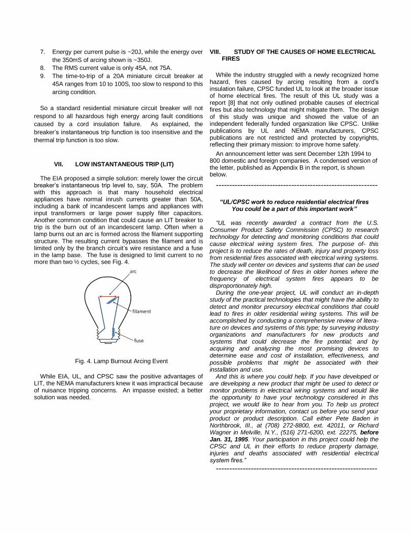
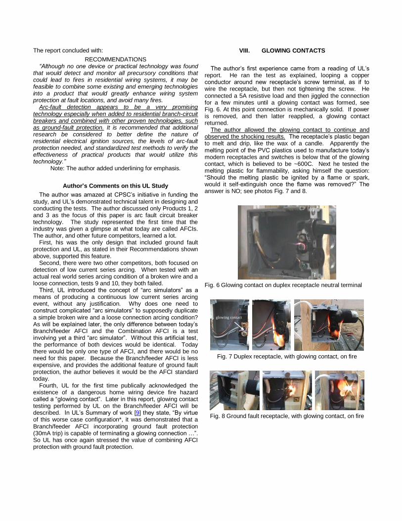
The author’s first experience came from a reading of UL’s report. He ran the test as explained, looping a copper conductor around new receptacle’s screw terminal, as if to wire the receptacle, but then not tightening the screw. He connected a 5A resistive load and then jiggled the connection for a few minutes until a glowing contact was formed, see Fig. 6. At this point connection is mechanically solid. If power is removed, and then latter reapplied, a glowing contact returned.
The author allowed the glowing contact to continue and observed the shocking results. The receptacle’s plastic began to melt and drip, like the wax of a candle. Apparently the melting point of the PVC plastics used to manufacture today’s modern receptacles and switches is below that of the glowing contact, which is believed to be ~600C. Next he tested the melting plastic for flammability, asking himself the question: “Should the melting plastic be ignited by a flame or spark, would it self-extinguish once the flame was removed?” The answer is NO; see photos Fig. 7 and 8.
Fig. 6 Glowing contact on duplex receptacle neutral terminal
glowing contact
Fig. 7 Duplex receptacle, with glowing contact, on fire
Fig. 8 Ground fault receptacle, with glowing contact, on fire

A C
B D
Fig. 9 Twist-on wire nut with a glowing contact
Shown in Fig. 9 is a glowing connection at a twist-on wire connector. The photo to the left shows the original condition of wire nut at “A”. The photo to the right shows the results several minutes after glowing contact was initiated; “B” shows wire nut melted into two pieces, “C” shows the current carrying steel spring glowing, and “D” the insulation melted from the wire.
The other figures speak for themselves. The fact that a glowing contact can be created so easily indicates that glowing contacts are a major home fire hazard. Also a wiring device’s plastic that is heated by a glowing contact, once ignited will continue to burn. A home has hundreds of electrical connections. Each has the potential to start a fire. Because connections are behind the wall, a fire could burn undetected for quite a while.
There have been a number of articles on electrical connections [10]. The author’s first reference to the theory of a glowing contact was a Norwegian paper [11]. The paper discussed the electrical behavior of a glowing contact, which indicated that it represented a negative resistance. That is, as the current increases, the voltage decreases, creating a range of near constant power. It also results in the current being crowded into a very small area, about the cross-section of a human hair. This extreme current crowding creates very high local power dissipation; thus the glow.
The author has easily formed a glowing contact with currents from 0.5A to 15A. An excellent discussion of the glowing contacts, with photos, is available in a book [12] by Vytenis Babrauskas, Ph.D. The glowing contact references were from Japan, a country whose homes are by construction very flammable.
The two people whose commitment to electrical safety that most impressed the author during the AFCI development process were Dr. Vytenis Babrauskas and Mike Holt (www.Mike Holt.com), they both witnessed the hazard of a glowing contact.
IX. NEMA AFCI CIRCUIT BREAKER TASK FORCE A Task force was formed from representatives of each
manufacturer: its purpose was to develop a Standard for AFCI circuit breakers. Once developed it would be given to UL to maintain (manufacturers, not UL, develop UL Standards). Eventually the Standard would be adopted by the American National Standards Institute (ANSI).
The author was selected to be a representative. He was honored, and looked forward to the assignment. This was his second experience on such a task force. The first was as the US representative on an International Electrotechnical Commission (IEC) Task Force. This group was assigned the task of developing a Standard for new electronic trip units,
which were replacing the traditional older electro-mechanical protective relay devices.
The IEC experience was enjoyable, a pleasant surprise. There were only five Task Force members, one each from Italy, England, France, Spain, and himself from the US. They met in Paris and Zurich hotel rooms. Members were technically competent and committed to developing a good Standard to enhance safety. Work was completed in less than a year; today the Task Force’s output is Appendix J of IEC 60947-2.
In contrast, the author’s experience as a member of the NEMA AFCI Task Force was very disappointing and frustrating. There were about eight members, representing the major circuit breaker manufacturers. Three companies dominated the discussions, the same companies that provided Products 1, 2, and 3 to the UL study. The other companies appear to have had no “hands on” experience in terms of testing or design.
The Task Force members were skilled Codes and Standards professionals, with the exception of the author. These are corporate employees whose job description includes support of their Corporation’s position relative to Code (NEC) and Standards (UL and IEC) issues. I found them all to be friendly, ethical, talented, and very skilled debaters. The first meeting clearly established what, over the next few years, was to be two opposing positions.
a. There was the “Product 3” stated position. The Task Force should start by reviewing UL’s “Study of the Causes of Home Electrical Fires” report and should address as many causes as possible. This included the issue of the glowing contact, and therefore the inclusion of ground fault. All testing should be “real world”, no arc simulators etc.
b. The other was the “Product 1&2” position. They argued that the Task Force’s charge from NEMA was to address arcing issues only; a glowing contact once formed doesn’t involve arcing, neither does a ground fault. Further the arc simulator does produce an arc, so they should be used.
The positions were diametrically opposite, only partial agreement was reached early on for some sort of parallel arc fault testing. The unspoken issue involved the fundamental differences in the technology of the two positions. While one could guess at the technology, no patents had yet issued and no AFCI products were commercially available for testing. From the UL reports one could postulate that Products 1 and 2 were focused on responding to low current series arcs, by detection of high frequency current noise. Product 3 can best be described as an enhanced GFCI with a sensitive instantaneous trip. Years later these assumptions were found to be true. These differences are reflected in today’s Combination AFCIs and Branch/feeder.
The proprietary technologies were never discussed, for legal reasons. Most of these meetings were held at NEMA’s headquarters, and a NEMA employee attended all of the meetings.
So the Task Force limped along and as the Chair once said, “We are moving full speed towards an impasse!” The Product 1&2 team wanted to require tests involving the arc simulators, Product 3 wanted only real world testing. The Chair tried to resolve this by having the Task Force fund UL to create a new “real world” series arc test. What he wanted was a test that

involved a break in a cord’s conductor. An optical fire indictor would be used to determine the arcing duration required to start a fire, at different values of load currents. When plotted some referred to this as the “fire curve”.
The author felt this study was a waste of time; he and others had spent months trying to create more than a spark across a gap in a cord’s conductors. After more than a hundred years, Paschen's Law still applies.
X. The UL “Fire Curve” After a few months the UL engineer reported his findings to
the Task Force, he had the “fire curve”. See Fig. 10 taken from Dr. Vytenis Babrauskas’ book (Figure 71).
Fig. 10 UL’s “Fire Curve”
Fig. 11 UL “Fire Curve” test circuit
Fig. 12 UL “Fire Curve” test sample
An examination of Fig. 10 shows that UL labeled the x-axis as “Available short-circuit current (A)”, not load current. The test circuit is shown in Fig. 11; a cord specimen ready for testing is shown in Fig. 12. There was no load connected to the cord (SPT-2). The resistor shown was used to adjust the available short-circuit current from a low of 1A to a high of 100A. The UL engineer acknowledged that he performed parallel arcing tests, not the series arcing tests he was funded to conduct.
The preparation of the test samples is very complicated, and dangerous.
The following words were taken from today’s UL1699 AFCI Standard, Section 40.4 Carbonized path arc clearing time test
40.4.2 Specimens of Type SPT-2 16 AWG (1.3 mm2) cord are to be prepared as follows:
a) The cord specimens are to be cut to a minimum length of 8 inches (203 mm) and the individual wires separated at each end of the cord specimen for 1 inch (25.4 mm).
b) The insulation across both wires is to be slit 2 inches (50.8 mm) from one end to a depth to expose the conductors without severing any strands.
c) The slit in the insulation is to be wrapped with a double layer of electrical grade black PVC tape and overwrapped with a double layer of fiberglass tape.
d) The conductors are to be stripped at the end farthest from the slit approximately 1/2 inch (12.7 mm) for connection to the test circuits.
40.4.3 The cord specimens shall be conditioned using a supply of sufficient voltage(s) and current(s) to rapidly pyrolyze the insulation at the slit in the cord and create a carbonized conductive path across the insulation between the cord conductors. The carbonized path shall be considered complete if a 100 W incandescent lamp in series with the path draws 0.3 A or can start to glow at 120 V. The following steps are one method that is known to produce such a carbonized path.
So the wire sample is prepared as a parallel, not a series, fault.
Author’s note: Wire preparation is dangerous. Two transformers are required, 7kV @ 30mA and 2kV @ 300mA.

Shown in Fig, 13 is a photo taken during one such test. Smoke and flames are shown coming from the fiberglass tape, see step c. The tape is a UL Recognized component, often used by electricians to cover electrical connection.
Fig. 13 Smoke and flames originating from the area of fiberglass tape.
The smoke and fire surprised the author, so he ran a simple flammability test on a piece of fiberglass electrical tape, see Fig. 14.
Fig. 14 Flammability test of glass electrical tape
The tape is obviously VERY flammable and its use to cover electrical connections is probably not wise. Also using it as part of UL 1699 is hard to explain.
The test method that produced the “Fire Curve” is as follows:
1. Prepare wire sample.
2. Adjust variable resistor shown in Fig. 12 to provide desired Available Short Circuit Current, at test terminals where cord sample will be placed.
3. Install test sample
4. Provide means to record duration of arcing, prior to flame detection
5. Record data point with x-axis as Available Short Circuit Current and y-axis as time-to-flame
6. Repeat test at each current a number of times.
7. Draw a line through minimum time-to-flame at each current.
8. This minimum time establishes the maximum time an AFCI test sample is allowed to carry arcing current before tripping, when tested with a prepared wire sample.
What was the Task Force to do now?
The Task Force Chair had arranged for UL to develop a “real world” series arc test involving arcing across a break in a cord’s conductor, as a way to break the impasse between Product 3 and Product 1-2 supporters. The first wanted only “real world” tests, the second insisted on the use of “series arc simulators”. An actual series arc event, such as arcing across a loose terminal or a break in cord’s conductor, wasn’t acceptable as UL had already shown that Product 1-2 would not respond to such an actual events (see UL Study tests 9 and 10).
The author was present at NEMA headquarters when UL presented the new “series arc” test. Available short-circuit current at the cord’s parallel fault was set as low as 1A, even though UL had earlier established the minimum available short-circuit current (Isc) as 75A (see Fig. 2). If an actual length of Type SPT-2 16 AWG cord had been used to establish the 1A current, instead of a fixed resistor (see Fig. 12), a cord length of about one mile would have been required. Besides these major issues, the engineer had inadvertently introduced highly flammable fiberglass tape and the use of dangerous high voltage transformers.
UL had simply developed yet another “series arc simulator”, this time using SPT-2 cord, instead of carbon and phosphor-bronze, or carbon and copper electrodes. The author assumed NEMA would reject the test. Instead, it was accepted although not made mandatory, or so he thought.
As will be explained in the section discussing UL1699, the fire curve later became the UL1699 40.4 Carbonized path arc clearing time test. This test is the only arc performance test difference between the Branch/feeder and the Combination AFCI.
After accepting the test, the Task Force admitted its failure to develop a Standard, and turned the task over to UL. This is not a normal UL responsibility; manufacturers develop Standards, and UL is paid to test and list products to these Standards.
XI. NATIONAL ELECTRIC CODE, UL LISTING, AND UL STANDARDS
All three of these items are interlaced, and without them there will be little demand for a product.
Demand develops from an item being mandated in the National Electric Code (NFPA 70). In the case of the AFCI, the term AFCI was first introduced in NEC 1999 as paragraph 210.12 Arc-Fault Circuit-Interrupter Protection. The words “… branch circuits supplying outlets installed in dwelling unit bedroom shall be protected by a listed arc-fault circuit interrupter …” The enforcement date was delayed until the NEC 2002 Code cycle; the Code is revised every 3 years.
The word “listed” is an NEC term. The home inspector or “authority having jurisdiction” (AHJ) will look for a label on a product stating that it was Listed for the application by a recognized national testing laboratory (NRTL), such as UL. The label usually includes the UL Standard to which it was Listed.
So a product cannot meet an NEC requirement, if it is not Listed. And it can’t be Listed without a Standard. So NEMA’s inability to develop a Standard was a serious home safety issue. The author considered it a disappointment and an embarrassment.
XII. 1999 NATIONAL ELECTRICAL CODE (NFPA 70)
So with no Standard, and the NEMA manufacturers hopelessly deadlocked in developing one, the author’s company decided to go it alone. A Code revision proposal was written and submitted for the NEC 1999 Code cycle. The first NEC 1999 meeting took place in January 1997 in Hilton Head. The technology was so new that it was expected that the Code Panel would not be familiar with it. To overcome this problem, a hospitality room was set up where the NEC meeting was held, so a live demonstration of AFCI technology could be given. The Code Panel No. 2 Chair (the Panel responsible for residential branch circuit wiring) informed his Panel of the opportunity for them to witness an arcing fault demonstration. He graciously delayed a vote on the AFCI proposal for a day to allow Panel members to see the demonstration.
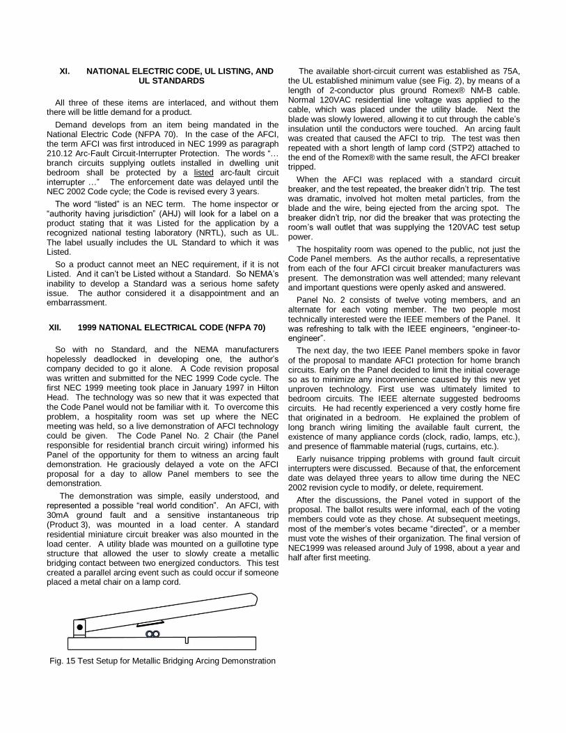
The demonstration was simple, easily understood, and represented a possible “real world condition”. An AFCI, with 30mA ground fault and a sensitive instantaneous trip (Product 3), was mounted in a load center. A standard residential miniature circuit breaker was also mounted in the load center. A utility blade was mounted on a guillotine type structure that allowed the user to slowly create a metallic bridging contact between two energized conductors. This test created a parallel arcing event such as could occur if someone placed a metal chair on a lamp cord.
Fig. 15 Test Setup for Metallic Bridging Arcing Demonstration
The available short-circuit current was established as 75A, the UL established minimum value (see Fig. 2), by means of a length of 2-conductor plus ground Romex® NM-B cable. Normal 120VAC residential line voltage was applied to the cable, which was placed under the utility blade. Next the blade was slowly lowered, allowing it to cut through the cable’s insulation until the conductors were touched. An arcing fault was created that caused the AFCI to trip. The test was then repeated with a short length of lamp cord (STP2) attached to the end of the Romex®
with the same result, the AFCI breaker
tripped.
When the AFCI was replaced with a standard circuit breaker, and the test repeated, the breaker didn’t trip. The test was dramatic, involved hot molten metal particles, from the blade and the wire, being ejected from the arcing spot. The breaker didn’t trip, nor did the breaker that was protecting the room’s wall outlet that was supplying the 120VAC test setup power.
The hospitality room was opened to the public, not just the Code Panel members. As the author recalls, a representative from each of the four AFCI circuit breaker manufacturers was present. The demonstration was well attended; many relevant and important questions were openly asked and answered.
Panel No. 2 consists of twelve voting members, and an alternate for each voting member. The two people most technically interested were the IEEE members of the Panel. It was refreshing to talk with the IEEE engineers, “engineer-to-engineer”.
The next day, the two IEEE Panel members spoke in favor of the proposal to mandate AFCI protection for home branch circuits. Early on the Panel decided to limit the initial coverage so as to minimize any inconvenience caused by this new yet unproven technology. First use was ultimately limited to bedroom circuits. The IEEE alternate suggested bedrooms circuits. He had recently experienced a very costly home fire that originated in a bedroom. He explained the problem of long branch wiring limiting the available fault current, the existence of many appliance cords (clock, radio, lamps, etc.), and presence of flammable material (rugs, curtains, etc.).
Early nuisance tripping problems with ground fault circuit interrupters were discussed. Because of that, the enforcement date was delayed three years to allow time during the NEC 2002 revision cycle to modify, or delete, requirement.
After the discussions, the Panel voted in support of the proposal. The ballot results were informal, each of the voting members could vote as they chose. At subsequent meetings, most of the member’s votes became “directed”, or a member must vote the wishes of their organization. The final version of NEC1999 was released around July of 1998, about a year and half after first meeting.

The wording in NEC 2002 was:
210.12 Arc-Fault Circuit-Interrupter Protection. (A) Definition. An arc-fault circuit interrupter is a device intended to provide protection from the effects of arc faults by recognizing characteristics unique to arcing and by functioning to de-energize the circuit when an arc fault is detected.
(B) Dwelling Unit Bedrooms. All branch circuits that supply 125-volt, single-phase, 15- and 20-ampere outlets installed in dwelling unit bedrooms shall be protected by an arc-fault circuit interrupter listed to provide protection of the branch circuit.
So the NEC 1999 mentioned AFCI, and NEC 2002 was to require it. Now UL had to develop and release an AFCI standard, so manufacturers could “List” their products to the standard. A clock was ticking.
XIII. UL 1699 Arc-Fault Circuit Interrupters
UL called a meeting at their Chicago headquarters to report their progress in converting the NEMA AFCI draft into a UL standard. When the author walked into conference room he thought he would see only a few UL engineers and the NEMA Task Force. He was wrong; the room was filled with representative from the three groups of NEMA manufacturers who provide UL Listed electrical system components for the home. These three groups are: circuit protective devices (circuit breakers, GFCI, fuses, etc.), wiring devices (switches, receptacles, GFRs, dimmers, etc.), and wiring (electrical cables and cords).
The NEMA draft was now titled UL 1699 ARC-FAULT CIRCUIT-INTERRUPTERS. UL had taken the four arc fault performance tests that NEMA had developed and created what is now UL 1699 Table 34.2, see Fig. 16. Two product types are shown, the Branch/feeder and the Combination AFCI. These are new terms introduced by UL.
Table 34.2
Arc fault detection tests table
Table 34.2 effective February 10, 2008
Tests Branch/feeder Combination
AFCI AFCI
40.2 Carbonized path arc ignition test X X
NM-B insulation cut
40.3 Carbonized path arc interruption test
SPT-2 insulation cut X X
NM-B insulation cut
40.4 Carbonized path arc clearing time test
SPT-2 insulation cut X
40.5 Point contact arc test
SPT-2 insulation cut X X
NM-B insulation cut X X
Fig. 16 Test Requirements for Branch/feeder and
Combination AFCIs
UL introduced the concept of additional product types including: Outlet AFCI, Portable AFCI, Cord AFCI, and LCDI. None of these AFCIs types are available today. If available, they alone would not meet NEC requirement for branch circuit protection so market would be limited. The LCDI is available, but it’s not an AFCI.
Looking at Fig. 16, there is only one arcing test difference between a Branch/feeder AFCI (now NEC disallowed) and a Combination AFCI (NEC mandated). The test was given the name “Carbonized path arc clearing time test”. Notice that it is described as an “SPT-2 insulation cut” test. It is a parallel, not a series arcing test. A description of this test is given in Section X. It is the “Fire Curve” test, returning under a new name.
UL made a major revision to the “fire curve” (see Fig. 10) as they transitioned it into UL 1699. Most significantly while the fire curve covered currents from 1 to 100A, the Standard covers testing over a range of only 5 to 30A. Very few appliance cord’s carry a current of 5A or higher. Excluded are clocks, lamps, radios, TVs, entertainment centers, and most electrical appliances found in a home’s living areas. The only load the author can think that would draw more than 5A would be a space heater, not usually found in new home living areas.
So UL had established that the Combination AFCI was the “golden medal” winner in AFCI technology race, because it has to pass their “Carbonized path arc clearing time test”. The word “Combination” simply means it must meet all, or a combination, of the four arcing fault tests in UL1699. It has nothing to do with series arcing, as defined by UL. Yet UL on their web site [6] state that a Combination AFCI provides “Series Arcing Detection” of “Branch-circuit Wiring” and “Cord Sets (Extension Cords), Power-supply Cords”.
XIV. UL STUDY OF THE BRANCH/FEEDER AFCI’S ABILITY TO MITIGATE THE FIRE HAZARD OF A
GLOWING CONTACT.
The hazard of glowing contacts was discussed in earlier in GLOWING CONTACTS section VIII. No one who has seen a demonstration of this condition would argue that it isn’t a serious potential home fire hazard. The words first appeared in a UL Standard in UL 1699. The words are interesting, and not typical for a UL standard, as they describe a safety hazard which is not covered by the standard.
Paragraph 1.3 of UL 1699 states: “These devices are not intended to detect glowing connections.”
These words were introduced by the NEMA Task Force at one its earliest meeting. At the time the author was advocating the inclusion of ground fault protection to the AFCI requirement, as GF plus AF protection had been shown to be effective in mitigating the effects of a glowing contact. As mentioned earlier, the UL Report [8] stated:
“Arc-fault detection appears to be a very promising technology especially when added to residential branch-circuit breakers and combined with other proven technologies, such as ground-fault protection.”
The Task Force had already voted to exclude a ground fault requirement, so it next had a problem with the issue of glowing contacts. Not to address the subject of glowing contact would
be an embarrassment, as the UL Report had described this as a serious home wiring hazard. The initial suggested wording was “These devices do not mitigate the effects of glowing connections.” The author argued successfully against the words, as with ground fault they do provide mitigation. A consensus was reached, over the author’s objection, that added the strange words “not intended to” thus leaving it to the reader to guess, “Do they or don’t they?”
So the AFCI Standard understates the value of a Branch/feeder AFCI in mitigating the effects of a glowing contact. In an attempt to publicize this fact, the author’s company decided to fund UL to run extensive testing of the Branch/feeder AFCIs involving glowing contacts. The testing lasted a week, involved testing eight AFCIs at same time. The complete test report can be downloaded from Mike Holt’s web site [9].
The Report’s Summary states that “a Branch/feeder AFCI incorporating equipment ground fault protection (30 mA trip) is capable of terminating a glowing connection by sensing the differential current associated with thermal degradation of the wiring device insulating material(s).” Once again UL stated the value of combining GF with AFCI protection.
XV. 2005 NATIONAL ELECTRICAL CODE (NFPA 70)
The subject of the “Combination AFCI” was first introduced by Manufacturer X during the 2005 code cycle. Their proposal [2] was simple, required the addition of only two words (combination type) to the Code.
210.12 Arc-Fault Circuit-Interrupter Protection.
(A) Definition. An arc-fault circuit interrupter is a device intended to provide protection from the effects of arc faults by recognizing characteristics unique to arcing and by functioning to de-energize the circuit when an arc fault is detected.
(B) Dwelling Unit Bedrooms. All 120 volt, single phase, 15 and 20-ampere branch circuits supplying outlets installed in dwelling unit bedrooms shall be protected by a listed arc-fault circuit interrupter, combination type installed to provide protection of the entire branch circuit.
The proven Branch/feeder AFCI type, the only type that was available at the time and had been installed in new homes since 2002, would be disallowed.
Proposals for consideration during the NEC 2005 code cycle had to be submitted by late 2002. Manufacturer X first introduced a Listed Combination AFCI circuit breaker for sale on October 1, 2006. So Manufacturer X’s Combination AFCI was not commercially available, for 3
rd party testing, until an
incredible four years after their proposal was submitted. It also would not have been available to meet the NEC 2005 requirement.
The author and others assumed Code Panel No. 2 would reject the proposal; they elected not to attend the NEC 2005 kick off meeting in Hilton Head. This proved to be a huge mistake. The author received a panicky call from a colleague who was at the meeting, he said the Panel was “angry”, was seriously considering accepting Manufacturer X’s proposal. Ultimately they did.
The next important NEC 2005 meeting was held in December 2003, in San Diego. An attempt was made to convince the Panel that their action was at best premature, but the Panel was convinced that the Combination AFCI was so important, that all other AFCIs should be disallowed. Manufacturer X conducted no open public demonstration of their Combination AFCI, so important 3
rd party critique was not
possible. This is in marked contrast to the NEC 1999 code cycle, during which the author and his colleagues conducted a totally open demonstration of the features of what is now called a Branch/feeder AFCI.
During the public deliberation the NEMA voting Panel member spoke in favor of his company’s proposal. This surprised the author who thought the NEMA position was to not support the Manufacturer X proposal.
A Panel member also said that the Panel was misled; the product they approved did not perform as expected. The Panel didn’t ask him to explain his words, they seemed to know. This reaction, taken together with the fact that the author was told the Panel was “angry”, caused the author to believe that the Panel was angry with him and his colleague for their presentation to the Panel during the NEC 1999 cycle. How could anyone who saw the demonstration of the features of a Branch/feeder AFCI believe they were misled?
Fortunately one Panel member was able to convince enough of his colleagues to at least add the words:
“Branch/feeder AFCIs shall be permitted to be used to meet the requirement of 210.12(B) until January 1, 2008.”
So nothing would change until the NEC 2008 code cycle, there was time to correct the Panel’s error. The author tried unsuccessfully three times, see next sections.
XVI. CODE PANEL NO. 2
The author’s contacts with Panel No. 2 members during the Code meetings were positive. They are a dedicated group of individuals who spend many hours every three years reviewing hundreds of proposed Code revisions [13]. The process is formal, guest speakers are recognized, and discussion and voting are open and public. While a number of members have a direct financial interest in the decisions, others participate purely to improve electrical safety. An oddity is the role that CPSC plays. This is an agency whose primary mission is to improve consumer safety, yet their Panel member has no vote. That’s unfortunate as their input would be very valuable.
XVII. UL 1699 STP JUNE 23rd 2005
The author’s next attempted again to address the two major technical problems with the Combination AFCI;
1. The lack of a ground fault requirement, and
2. The inclusion of the “Carbonized path arc clearing time test”.
This was done at a Standards Technical Meeting (STP) held at UL’s Chicago Headquarters. The STP process was established by UL as a formal method for maintaining an existing standard. UL tries to create a diverse group of
members, not just NEMA manufacturers. Much like the NEC process suggested standard edits can be proposed. After the proposal is presented and discussed, a vote is taken to accept or reject the proposal.
Ground Fault Requirement
To realistically demonstrate the need for a ground fault test; the author conducted a simple glowing contact test for all to see. Test was conducted on a UL lab bench. He plugged a 60W lamp (0.5A) load into a new duplex receptacle, turned the lamp on, and then jiggled a loose receptacle wire connection until a glowing contact formed. This took about a minute. Once established the contact was stable, the lamp burned steady with no indication of a problem, while the receptacle plastic near the connection melted and dripped. The plastic wire insulation on the glowing conductor also melted. For about thirty minutes the STP members stood around the bench, observed the glowing contact, and discussed the problem.
The demonstration showed a new UL Listed wiring device, connected to a UL Listed cable, presenting what clearly is a serious home fire hazard. The ability of an AFCI circuit breaker, with ground fault protection, to mitigate the event was obvious to all. The bare glowing line conductor, if installed in an electrical box, would likely touch either the other supply conductor or the ground conductor, creating an arcing fault. The need for ground fault protection comes from the condition when the glowing contact develops on the neutral conductor. Under this condition if the glowing neutral touches the ground conductor, there would be no arcing as the conductors are at the same potential. A ground fault is created however.
The earlier UL glowing contact report [9] was established as a “worse case”. The receptacles were not mounted in electrical boxes; wires were positioned so they couldn’t touch. This UL test demonstrated that as a receptacle’s plastic melts, the insulation between the glowing contact’s terminal metal parts, and the receptacle’s internal ground plate, is compromised creating a ground fault.
The combination of arc fault and ground fault, in a circuit breaker, was and is the only solution to this recognized home electrical fire hazard. The author thought his demonstration, together with the UL report, would convince all to support his company’s proposal to add a 30mA ground fault requirement. This would require no product redesign, as all AFCIs at the time already including this feature. He was wrong.
The voting initially went as expected. Those not associated with NEMA and UL by in large voted in favor. The NEMA wiring device manufacturers voted against the proposal; this was expected and understood. Requiring every branch circuit breaker to provide ground fault protection could negatively affect their ground fault receptacle business. Next came a surprise: an AFCI manufacturer, whose product already included ground fault, voted against it. This made no sense, but the Panel still had enough votes to pass the proposal. A 2/3 positive vote was required to pass the proposal. It was expected that UL would vote in favor, they had on multiple occasions publically supported the proposal. Without explanation, UL switched position and voted against proposal. The 2/3 requirement failed by one vote.
“Carbonized path arc clearing time test”
This test was discussed earlier, it makes no sense. It was thought that if the technical issues were honestly presented and discussed at this STP meeting, the test would be removed from UL 1699. Once removed, the Branch/feeder and Combination requirements would be the same (see Fig. 16), so there would be only a Branch/feeder AFCI. The mandate of NEC 2005 would be moot, as there would be no Combination AFCI.
The author was permitted to speak to the group for about half an hour. The test was carefully described including the important fact that it represented nothing more than a carefully prepared parallel fault in a VERY long extension cord. Available short-circuit fault currents as low as 5A were used, even though UL had earlier determined that the lowest available current in a home was 75A (see Fig. 2). It was not a series arcing fault and had nothing to do with home electrical safety.
The vote was along “party lines”. NEMA manufacturers, with a few exceptions, and UL voted against removing test. This block of votes exceeded the 1/3 required to defeat the proposal, so it failed. The “Carbonized path arc clearing time test” would remain in UL 1699.
XVIII. 2008 NATIONAL ELECTRICAL CODE (NFPA 70)
Next was the kick-off meeting for NEC 2008, again in Hilton Head. Time was running out to get the Combination AFCI removed as a requirement. By now NEMA members had accepted the Combination AFCI as inevitable, focus was on expansion.
The author attended the meeting, and as usual heard the NEMA and UL voting members speak of the importance of the series arc protection. After all the prepared presentations were completed, the Chair asked if anyone in the room would like to speak before the vote was held. The author felt he had an ethical and moral responsibility to speak, as the Panel clearly didn’t understand the Combination AFCI that they about to force new home builders to buy. He spoke as an individual, his words were not necessary supported by his company. He made two statements to the Panel:
1. “There is no test in the UL AFCI standard that involves testing that an AFCI will respond and trip due to arcing across a break in a cord’s conductor.”
2. “No one has yet demonstrated that a Combination AFCI will trip in response to a loose connection or arcing across a break in a cord’s conductor.”
A Code Panel No. 2 member, the same one who was able to delay the Combination AFCI mandate from 2005 to 2008, responded to these statements by asking two questions.
First he asked of UL if there is a test that involves tripping in response to arcing across a break in a cord’s conductor. The UL Panel member answered yes. After the meeting I challenged him on his answer. He said that the UL engineer who developed the test considers his test to be equivalent to a series arcing test. That answer did not match the question, and again UL disappointed the author.
The Panel member next asked a question of the Manufacturer X engineering manager, would his Combination

AFCI respond and trip in response to arcing at a loose connection. Again the answer was yes, however he added that the arcing had to become continuous. The author thinks this answer may have been a simple, but serious, mistake. Arcing at a loose connection is not continuous, because of Paschen's Law.
So this was one of the last discussions before the vote. The proposal to expand coverage with the Combination requirement, passed 8 “for” and 4 “against”, the bare minimum required 2/3 majority. The Panel member who asked the questions of UL and Manufacturer X voted “for” the proposal. The author believes this Panel member would have voted “against”, the proposal would have been defeated, if UL or Manufacturer X had answered differently.
XIX. PERFORMANCE AND COST
Reduced Performance
The newer Combination AFCIs do not provide 30mA ground fault protection, and thus they provide less protection than the less expensive and now disallowed Branch/feeder AFCI. The claim of “series arc” protection is at best unproven. Further, while the hazard of a glowing contact due to a loose connection or a broken conductor is understood, the claim that series arcing, related to such an event, can start a fire has not been demonstrated. The author and others have tried and failed.
Higher Cost
Branch/feeder designs, except Manufacturer X’s, are based on custom analog circuitry, e.g. US Patent 7,952,842. They combine parallel arc fault detection with standard ground fault circuitry. The arc fault circuitry adds little to the base ground fault cost. The Manufacturer X design requires a microcomputer, plus custom analog circuitry. It is inherently more expensive. All Combination AFCI designs are also microcomputer based, e.g. US Patent 7,558,033.
So a new home builder, as the result of NEC 2008, must typically purchase 20 Combination AFCIs. How much does disallowing the less expensive Branch/feeder add to the cost of a new home? The calculation requires knowing the cost of each type of AFCI. The average retail cost of a Combination AFCI, from Home Depot’s web site, is $37.07. The site doesn’t show the Branch/feeder, as NEC 2008 limits its demand.
There are two ways to calculate its cost. Adding the web site cost of a 20A circuit breaker ($4.07) to a ground fault receptacle’s cost ($12.58), yields a cost of $16.65. Another way to calculate today’s cost of a Branch/feeder AFCI is to start with the average cost of about $33 in 2002, the first year AFCI was mandated. At that time only bedroom circuits were covered, and enforcement was in only a few states. After nearly 10 years of continual design cost improvement, combined with annual manufacturing activity increases from tens of thousands to over a million, it’s reasonable to forecast today’s cost as half the 2002 cost, or $16.50. So today’s Combination cost about $20 more than the projected cost of the Branch/feeder.
The extra material cost of a new home as the result of NEC 2008 is 20 times $20, or $400. If the NEC 2014 removes the
Combination mandate, it will have been in effect for 6 years. Over that time, American home builders will have been forced to spend more than $1B extra for their homes.
XX. AUTHOR’S 2nd
ATTEMPT TO CLARIFY UL 1699
The author, after retiring, tried a second time, via the UL STP process, to correct problems with UL 1699. The first attempt in 2005 failed to make two changes: 1) add a 30mA ground fault test and 2) eliminate the “Carbonized path arc clearing time test”. The first would have improved an AFCI’s ability to respond to a glowing contact. The second would have eliminated the problem of manufacturers and UL mistakenly claiming that a Combination AFCI provides series arcing protection.
The 2nd
attempt started with the purchase [14] of the Standard in 2008. This is a very expensive ($1148) but necessary expense for anyone who wants to participate in the STP process. Next, working with UL, the author’s proposals were formatted in the form required by their computerized Collaborative Standards Development System (CSDS). The proposals were opened to the STP 1699 members for review October 29 2008.
The proposed changes to UL 1699 should have been acceptable to all STP members. It involved no core changes; it simply attempted to bring the Standard’s language in line with other UL standards. In particular, while the term “arcing” is defined in UL 1699, the UL terms “series arcing” and “parallel arcing” are not defined. Yet the manufacturers and UL on their web sites claim that the mandated Combination, unlike the Branch/feeder, provides “series arcing” protection of cords.
The author included these words as part of the required Rational for changes: “I believe the lack of definitions in UL 1699 for series and parallel arcing faults may have led to possible inadvertent false product claims. Including UL’s definitions of such faults, and associating them with each of the four tests listed in Table 34.2, will ensure against any possible future misunderstanding.”
During deliberations, via the web based CSDS process, NEMA members argued that the Standard needed no further clarification. The NEMA words were disappointing. In contrast UL tried to explain, using Fig. 11 (UL “Fire Curve” test circuit), that since the AFCI circuit breaker, the resistor, and the wire fault are in series, fault is thus a series fault. The UL words were disturbing and seemed to indicate lack of basic electrical engineering knowledge. Confusing a “series circuit” with a “series fault” is hard to explain, especially since UL developed and published the definition of a “series fault”.
The STP ballots were due May 11, 2009. A total of 19 votes were cast. The proposal was defeated 11 “against” and 8 “for”. The NEMA manufacturers and UL cast all of their 10 votes “against”, only 7 “against” votes were required to defeat proposal. The members not associated with NEMA or UL voted 8 to 1 in favor of proposed changes. Manufacturers and UL have votes to block any change.
The author questions the value of the STP process.

XXI. 2014 NATIONAL ELECTRICAL CODE (NFPA 70)
Proposal 1: Delete words “combination type”
The author plans to submit a two word deletion proposal to
2014 NATIONAL ELECTRICAL CODE (NFPA 70), removing
words combination-type (see section III). This paper will be
made available to Panel No. 2 as part of the required
justification. Also the Panel will be encouraged to request a
public demonstration of the claim mentioned earlier [7].
A series arc is an arcing incident across a break in a conductor. A common example is a cut across one of the two wires in a lamp cord, with a dangerous arc forming in the gap. Combination AFCI circuit breakers detect the arcing condition and turn off the circuit, thus providing the enhanced protection.
This is a simple and safe manufacturer defined test that
requires only a Combination AFCI and lamp, no other
equipment. The test can be performed safely in the
conference room, during Panel No. 2’s deliberation.
Proposal 2: Add a 30mA ground fault requirement
Removing the Combination AFCI mandate from NEC 2014 would correct a serious Code dilemma, the mandating of a device whose claims are unproven. It will not however address the serious issue of the glowing contact. Having spent more than a decade working with both NEMA and UL, the author has concluded that adding a 30mA requirement to the UL 1699 AFCI Standard will not happen, without an external influence.
At least three times, UL publically stated the value of combining AF and GF protection in mitigating a glowing contact, yet they blocked making it part of UL 1699 (see XVII).
Further this is the only technology proposed to address this recognized fire hazard. There are others known mitigating means. UL could require the wiring device plastics to not melt or burn, when subjected to the 600C temperature of a glowing contact. Circuit breakers use such plastics. These plastics are probably more expensive and harder to mold, thus one would think the wiring device manufacturers would support the ground fault proposal. The wire insulation would also need to survive 600C, so one would think wire manufacturers would also support the ground fault proposal.
One way to force NEMA and UL to add a 30mA test is to include it as a NATIONAL ELECTRICAL CODE (NFPA 70) requirement. This is what happened with NEC 1999 (see XII).
210.12 Are-Fault Circuit-Interrupter Protection. (B) Dwelling Units: All 125-volt, single-phase, 15- and 20- ampere branch circuits supplying outlets installed in dwelling unit family rooms, dining rooms, living rooms, parlors, libraries, dens, bedrooms, sunrooms, recreation rooms, closets, hallways, or similar rooms or areas shall be protected by a listed arc-fault circuit interrupter which includes earth leakage protection (30 mA trip sensitivity), combination-type, installed to provide protection of the branch circuit.
The standard for earth leakage protection is UL 1053 Ground-Fault Sensing and Relaying Equipment. So if Panel No. 2 accepts Proposal 2, manufacturers who want to meet NEC 2014 would simply need to List their product to both UL 1699 and UL 1053. No standard or code action by UL or NEMA is required.
This is what the author’s company did with their first AFC’s, they were dual Listed. See UL labels in Fig. 17 and 18.
Fig. 17 AFCI with 30mA Earth Leakage Protection
Fig. 18 Close-up of Label
The dual listing was eventually dropped, although all of my old company’s Branch/feeder AFCIs today still include a 30mA ground fault feature.

Proposal 3: Delete all references to receptacle outlet
The present wording assumes that a receptacle outlet AFCI provides the same performance as a circuit breaker AFCI. This ignores the UL recognized fire hazard presented by a receptacle with a glowing contact [9]. Embedding AFCI protection within a flammable plastic housing cannot be justified. In contrast the plastic used for a circuit breaker must safely tolerate a glowing contact.
From the UL AFCI standard (UL1699), “An outlet circuit AFCI shall comply with the materials requirements in 8.1 – 8.5 of the Standard for Attachment Plugs and Receptacles, UL 498.” So the case of a receptacle outlet AFCI can melt and burn in the presence of a glowing contact.
In contrast, from UL489, “The case shall be of such material that it will withstand the most severe conditions likely to be met in service.” This includes a glowing contact.
A further issue involves requiring the outlet circuit AFCI to be the first receptacle on a branch. Measured short circuit fault currents at these location are as high as 5000A, a value that by test a receptacle GFCI (GFR) cannot survive. The outlet circuit AFCI is not now available; it is assumed its limited short circuit capability will be the same as that for a GFR. The author tried to have the 5000A value made a UL1699 outlet circuit AFCI requirement. Proposal was defeated.
XXII. CPSC DATA BASE
Earlier the author expressed his belief that CPSC is a very valuable, and underused, resource available to any person, company, or organization interested in improving home safety. A UL engineer made him aware in 2003 of a “phone-in” service they provide for those seeking records of reported home safety problem. They will do a phone search for records from a list of key words such as cord, fire, etc. that the caller provides. They then mail you a hard copy of their findings. The records are open, as names and product manufacturers are not included. This was 2003; hopefully service is still available.
The author called CPSC and spoke with a very helpful person. After conducting a number of searches, the person offered to send him the data base that was being used. He was requested to send CPSC two blank CDs and a self addressed stamped envelope, for mailing the CDs back. This was total cost. The author did as requested, and after about a week he received a Microsoft Access data base with the records. There were 10,031 records, covering years 1980 through 2002.
A search engine for the data base was developed that allows for two types of searches. The first is “x AND y AND z”, where AND is the logic operator. The second is “(w OR x) AND (y OR z)”, where OR is an operator. Using the search engine, the author conducted a number of searches.
XIV. AUTHOR’S WEB SITE
The author’s website http://www.combinationafci.com/ was
mentioned earlier. The original draft of this paper will be
available on the site. Two searches of the CPSC data base
will be available:
(outlet OR receptacle) AND fire
and
cord AND fire.PDF
The first relates to glowing contacts, 1409 records were
found. The second relates to parallel arcing due overheated
or damaged cord insulation. The latter search yielded 2235
records. Both are obviously major potential fire hazards, these
two searches yielded far more incidents than any other that
included the word “fire”. This seems to validate the original
concern of Electronics Industries Association (EIA) and CPSC
(see section V) that insulation failure of cords is a serious fire
hazard.
It is hoped that the CPSC Access data base with search
engine can also be made available on his web site. This will
allow anyone interested in improving home electrical safety to
do their own searches. Better yet would be for CPSC to
provide this simple web based type of search engine service.
XXIII. CONCLUSIONS
The primary goal of this paper was to describe what a
Combination AFCI circuit breaker can do, while also clarifying
what it can’t do. The features of the Combination AFCI, and
the earlier Branch/feeder AFCI, are listed in Table 1. Neither
provides series arc protection, the Branch/feeder provides the
extra important feature of 30mA ground fault protection.
The paper goes on to explain, but not justify, how the
Combination AFCI came to be mandated, while the
Branch/feeder that provides more protection at less cost is
disallowed. The key drivers behind this were the AFCI
manufacturers, their NEMA organization, and UL. The author
hopes this paper will stir discussions amongst the principals
and correct any errors that were made concerning their
products’ performance. This would also include supporting
removing the Combination AFCI mandate from the NATIONAL
ELECTRICAL CODE (NFPA 70).
Finally, the author, having participating actively during the
AFCI development, would encourage the IEEE engineering
communities of these great institutions to become more
engaged to insure their codes and standards representatives
fully understand the technical issues. These are their
products; they have a responsibility to insure their products are
not inadvertently misrepresented.

XV. REFERENCES
[1] http://www.geindustrial.com/cwc/Dispatcher?REQUEST=PRODUCTS&pnlid=3&famid=8&catid=36&id=cb-qafci
[2] http://static.schneider-electric.us/docs/ Circuit%20Protection/Miniature%20Circuit%20Breakers/ Arc%20Fault%20Circuit%20Interrupters- AFCI/0760HO0301.pdf [3] http://www.sea.siemens.com/us/internet-dms/btlv/ Residential/Residential-Murray/docs_ LoadCentersBreakersMurray/MYPM-COMBO-0907.pdf [4] http://www.platt.com/CutSheets/ Eaton%20Distribution/Breakers-Residential-ArcFault.pdf [5] http://www.afcisafety.org/products.html [6] http://database.ul.com/cgi-bin/XYV/template/ LISEXT/1FRAME/showpage.html?name= AWAH.GuideInfo&ccnshorttitle= Arc-fault+Circuit+Interrupters,+Combination+Type&objid =1074583378&cfgid=1073741824&version
=versionless&parent_id=1074583377&sequence=1 [7] http://products.schneider-electric.us/products-
services/products/circuit-breakers/miniature-circuit-breakers/combination-arcfault-circuit-interrupters/
[8] “Technology for Detecting and Monitoring Conditions that
could cause Electrical Wiring System Fires”, UL Project Number: NC233, 94ME78760, Contract Number: CPSC-C-94-1112, 1995
[9] www.mikeholt.com/htmlnews/afci/ ULreportonterminals.pdf [10] “Evaluations of Receptacle Connections and Contacts,”
Proceedings of the IEEE Conference on Electrical Contacts, Jesse Aronstein, 1993.
[11] “Glowing Contact Areas in Loose Copper Wire
Connections,” J. Sletback, R. Kristensen, H. Sundklakk, Norwegian Institute of Technology; and G. Navik, M. Runde, Norwegian Electric Power Research Institute; Proceedings of the Thirty-Seventh IEEE Holm Conference on Electrical Contacts, 1991.
[12] “Ignition Handbook”, Vytenis Babrauskas, Ph.D.
Published by Fire Science Publishers, Issaquah WA, USA, 2003.
[13] http://www.iaei.org/magazine/2003/07/ a-personal-view-of-nec-code-making-panel-2/ [14] www.techstreet.com/standards/ul/ 1699?product_id=1261946
XVI. VITA
Joe Engel graduated from University of Cincinnati in 1962 with a MSEE degree and University of Pittsburgh with a PhD in 1969. He worked as an electronic/electrical circuit designer/manager at Westinghouse’s Science and Technology Center, Pittsburgh PA from 1963 to 1993. From 1993 to 2007 he managed Eaton | Cutler-Hammer’s Electronic R&D Department. He served as a company adviser to numerous IEC, NEC, UL, and SAE panels. He holds over 100 US Patents and is a member of the IEEE and SAE.