combination puller/cutter - conair · combination puller/cutter instant access parts and service...
TRANSCRIPT

CombinationPuller/Cutter
Instant Access Parts and Service
(800) 458-1960(814) 437-6861
www.conairnet.com
The Conair Group, Inc.One Conair DrivePittsburgh, PA 15202Phone: (412) 312-6000Fax: (412)-312-6227
SCE and SCX Models
UGE048/0399
Installation
Operation
Maintenance
Troubleshooting

It is important to record the model and serial number(s) ofyour equipment and the date you received it in the UserGuide. Our service department uses this information, alongwith the manual number, to provide help for the specificequipment you installed.
Keep this User Guide and all manuals, engineering prints andparts lists together for documentation of your equipment.
Date:
Document Number: UGE048/0399
Serial number(s):
Model number(s):
Power Specifications:
AmpsVoltsPhaseCycle
DISCLAIMER: The Conair Group, Inc., shall not be liable for errorscontained in this User Guide or for incidental, consequential dam-ages in connection with the furnishing, performance or use of thisinformation. Conair makes no warranty of any kind with regard tothis information, including, but not limited to the implied warrantiesof merchantability and fitness for a particular purpose.
Record your equipment’smodel and serial num-ber(s) and the date youreceived it in the spacesprovided.
Copyright 1999 All rights reservedTHE CONAIR GROUP, INC.

UGE048/0399 SCE/SCX Combination Puller/Cutter
TABLE OFCONTENTS
INTRODUCTION . . . . . . . . . . . . . . . . . . .1-1Purpose of the User Guide . . . . . . . . . . . . . . . . . . . . . . . . .1-2How the Guide is Organized . . . . . . . . . . . . . . . . . . . . . . .1-2Your Responsibilities as a User . . . . . . . . . . . . . . . . . . . . .1-2ATTENTION: Read this so no one gets hurt . . . . . . . . . . .1-3How to Use the Lockout Device . . . . . . . . . . . . . . . . . . . .1-6
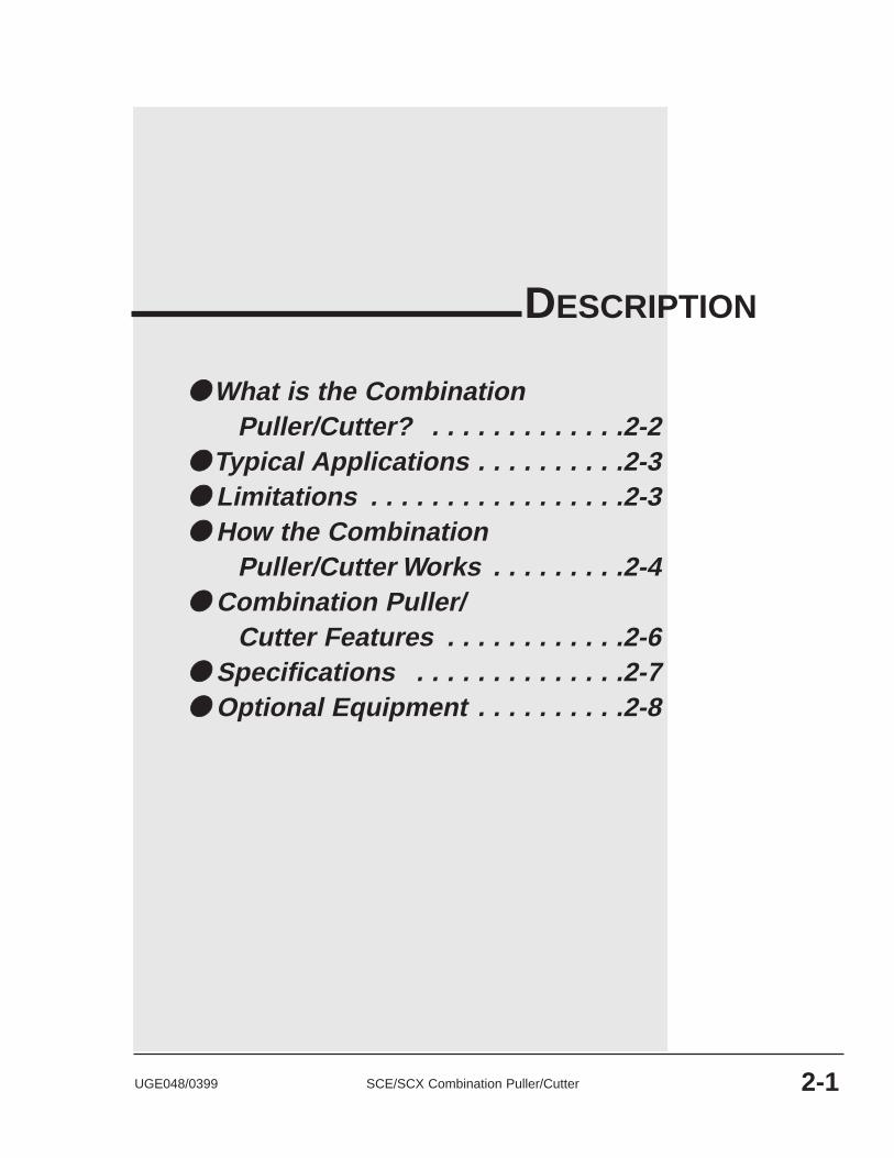
DESCRIPTION . . . . . . . . . . . . . . . . . . . .2-1What is the Combination Puller/Cutter? . . . . . . . . . . . . . . .2-2Typical Applications . . . . . . . . . . . . . . . . . . . . . . . . . . . . .2-3Limitations . . . . . . . . . . . . . . . . . . . . . . . . . . . . . . . . . . . .2-3How the Combination Puller/Cutter Works . . . . . . . . . . . .2-4Combination Puller/Cutter Features . . . . . . . . . . . . . . . . . .2-6Specifications . . . . . . . . . . . . . . . . . . . . . . . . . . . . . . . . . .2-7Optional Equipment . . . . . . . . . . . . . . . . . . . . . . . . . . . . . .2-8
INSTALLATION . . . . . . . . . . . . . . . . . . . .3-1Unpacking the Boxes . . . . . . . . . . . . . . . . . . . . . . . . . . . . .3-2Preparing for Installation . . . . . . . . . . . . . . . . . . . . . . . . . .3-3Positioning the Combination Puller/Cutter . . . . . . . . . . . . .3-4Connecting the Main Power Source . . . . . . . . . . . . . . . . . .3-6Installing the Cutter Blades . . . . . . . . . . . . . . . . . . . . . . . .3-8Mounting the Cutter Bushings . . . . . . . . . . . . . . . . . . . . . .3-9Adjusting Belt Tension . . . . . . . . . . . . . . . . . . . . . . . . . . .3-10Setting the Belt Gap . . . . . . . . . . . . . . . . . . . . . . . . . . . . .3-12Checking Repeatability . . . . . . . . . . . . . . . . . . . . . . . . . .3-14Repeatability Test Results . . . . . . . . . . . . . . . . . . . . . . . .3-15Checking Programming Values . . . . . . . . . . . . . . . . . . . .3-16Preparing for Testing . . . . . . . . . . . . . . . . . . . . . . . . . . . .3-17Testing the Installation . . . . . . . . . . . . . . . . . . . . . . . . . . .3-18
OPERATION . . . . . . . . . . . . . . . . . . . . . .4-1The Cutter Control . . . . . . . . . . . . . . . . . . . . . . . . . . . . . . .4-2The Puller Control . . . . . . . . . . . . . . . . . . . . . . . . . . . . . . .4-5Cutter Control Features . . . . . . . . . . . . . . . . . . . . . . . . . . .4-4Puller Control Features . . . . . . . . . . . . . . . . . . . . . . . . . . .4-8Combination Features . . . . . . . . . . . . . . . . . . . . . . . . . . . .4-9Before Starting . . . . . . . . . . . . . . . . . . . . . . . . . . . . . . . . .4-10Powering Up . . . . . . . . . . . . . . . . . . . . . . . . . . . . . . . . . .4-11Programming the Puller Speed . . . . . . . . . . . . . . . . . . . . .4-12Setting the Blade Speed . . . . . . . . . . . . . . . . . . . . . . . . . .4-12Choosing the Cutting Mode . . . . . . . . . . . . . . . . . . . . . . .4-13Setting the Cutting Mode . . . . . . . . . . . . . . . . . . . . . . . . .4-14Setting the Prescale Value . . . . . . . . . . . . . . . . . . . . . . . .4-15Checking Cut Quality . . . . . . . . . . . . . . . . . . . . . . . . . . .4-16Starting the Combination Puller/Cutter . . . . . . . . . . . . . . .4-16Making Adjustments During Operation . . . . . . . . . . . . . .4-17
i

SCE/SCX Combination Puller/Cutter UGE048/0399
OPERATION . . . . . . . . . . . . . . . . . . cont’dMaking Large Changes to the Puller Speed . . . . . . . . . . .4-17Fine-tuning the Puller Speed . . . . . . . . . . . . . . . . . . . . . .4-18Making a Manual Cut . . . . . . . . . . . . . . . . . . . . . . . . . . .4-18Counting the Number of Cuts . . . . . . . . . . . . . . . . . . . . .4-18Adjusting Cutter Preset Values . . . . . . . . . . . . . . . . . . . . .4-19Temporarily Stopping Cutting . . . . . . . . . . . . . . . . . . . . .4-19Stopping Only the Cutter . . . . . . . . . . . . . . . . . . . . . . . . .4-19Stopping the Combination Puller/Cutter . . . . . . . . . . . . . .4-20Shutting Down the Combination Puller/Cutter . . . . . . . . .4-20
MAINTENANCE . . . . . . . . . . . . . . . . . . . .5-1Maintenance Features . . . . . . . . . . . . . . . . . . . . . . . . . . . .5-2Warnings and Cautions . . . . . . . . . . . . . . . . . . . . . . . . . . .5-2Preventative Maintenance Schedule . . . . . . . . . . . . . . . . . .5-4Inspecting Cutter Blades . . . . . . . . . . . . . . . . . . . . . . . . . .5-6Inspecting Blade Hardware . . . . . . . . . . . . . . . . . . . . . . . .5-6Inspecting Cutter Bushing Screws . . . . . . . . . . . . . . . . . . .5-7Checking the Closure Latch . . . . . . . . . . . . . . . . . . . . . . . .5-7Checking Floor Locks . . . . . . . . . . . . . . . . . . . . . . . . . . . .5-7Cleaning the Lubrication Tray . . . . . . . . . . . . . . . . . . . . . .5-8Lubricating the Slide Rail . . . . . . . . . . . . . . . . . . . . . . . . .5-8Checking Grease Locations . . . . . . . . . . . . . . . . . . . . . . . .5-9Adjusting the Cutter Proximity Switches . . . . . . . . . . . . .5-10Replacing Motor Brushes . . . . . . . . . . . . . . . . . . . . . . . . .5-11Checking Electrical Connections . . . . . . . . . . . . . . . . . . .5-12Testing Belt Tension . . . . . . . . . . . . . . . . . . . . . . . . . . . .5-14Checking the Belt Gap . . . . . . . . . . . . . . . . . . . . . . . . . . .5-16Replacing Belts . . . . . . . . . . . . . . . . . . . . . . . . . . . . . . . .5-18Checking Torque . . . . . . . . . . . . . . . . . . . . . . . . . . . . . . .5-20
TROUBLESHOOTING . . . . . . . . . . . . . . . .6-1Before Beginning . . . . . . . . . . . . . . . . . . . . . . . . . . . . . . . .6-2A Few Words of Caution . . . . . . . . . . . . . . . . . . . . . . . . . .6-2Identify the Cause of a Problem . . . . . . . . . . . . . . . . . . . . .6-4Puller Operation Problems . . . . . . . . . . . . . . . . . . . . . . . . .6-5Cutter Operation Problems . . . . . . . . . . . . . . . . . . . . . . . . .6-7Product Quality Problems . . . . . . . . . . . . . . . . . . . . . . . .6-11Restoring Default Memory Settings . . . . . . . . . . . . . . . . .6-16Restoring User-Specific Memory Settings . . . . . . . . . . . .6-16Replacing Safety and Proximity Switches . . . . . . . . . . . .6-17Checking the Servo Amplifier . . . . . . . . . . . . . . . . . . . . .6-18Adjusting the Proximity Switches . . . . . . . . . . . . . . . . . .6-18Checking the Motor/Reducer Assembly . . . . . . . . . . . . . .6-19Testing Repeatability . . . . . . . . . . . . . . . . . . . . . . . . . . . .6-20Results of Repeatability Testing . . . . . . . . . . . . . . . . . . .6-21
ii
TABLE OFCONTENTS

UGE048/0399 SCE/SCX Combination Puller/Cutter
TABLE OFCONTENTS
APPENDIX . . . . . . . . . . . . . . . . . . . . . . . . .Customer Service Information . . . . . . . . . . . . . . . . . . . . . .A-1Warranty Information . . . . . . . . . . . . . . . . . . . . . . . . . . . .A-2Cutter Blade Selection and Use . . . . . . . . . . . . . . . . . . . . .B-1Cutting Tips . . . . . . . . . . . . . . . . . . . . . . . . . . . . . . . . . . .B-3Calculating Blade Interruption . . . . . . . . . . . . . . . . . . . . . .B-4Conair Cutter Blades . . . . . . . . . . . . . . . . . . . . . . . . . . . . .B-6All About Cutter Bushings . . . . . . . . . . . . . . . . . . . . . . . .C-1Blade and Bushing Lubrication . . . . . . . . . . . . . . . . . . . . .D-1Choosing Belt Materials . . . . . . . . . . . . . . . . . . . . . . . . . .E-1Conair Belts . . . . . . . . . . . . . . . . . . . . . . . . . . . . . . . . . . .E-1Puller Control Settings . . . . . . . . . . . . . . . . . . . . . . . . . . . .F-1Advanced Procedure: PID Tuning . . . . . . . . . . . . . . . . . . .F-3Using the Digital Belt Gap Sensor . . . . . . . . . . . . . . . . . .G-1Adjusting the Pneumatic Upper Belt Actuator . . . . . . . . . .G-2
PARTS/DIAGRAMSThis section has been provided for you tostore spare parts lists and diagrams.
iii


1-1UGE048/0399 SCE/SCX Combination Puller/Cutter
●● Purpose of the User Guide . . . .1-2●● How the User Guide
is organized . . . . . . . . . . . . . . .1-2●● Your Responsibilities
as a User . . . . . . . . . . . . . . . .1-2●● ATTENTION: Read this so
no one gets hurt . . . . . . . . . . .1-3●● How to Use the
Lockout Device . . . . . . . . . . . .1-6
INTRODUCTION

SCE/SCX Combination Puller/Cutter UGE048/03991-2 INTRODUCTION
This User Guide describes the Conair Combination Puller/Cutter and explains step-by-step how to install, operate, main-tain and repair this equipment.
Before installing this product, please take a few moments toread the User Guide and review the diagrams and safety infor-mation in the instruction packet. You also should review man-uals covering associated equipment in your system. Thisreview won’t take long, and it could save you valuable instal-lation and operating time later.
Symbols have been used to help organize the User Guide andcall your attention to important information regarding safeinstallation and operation.
Symbols within triangles warn of conditions that couldbe hazardous to users or could damage equipment.Read and take precautions before proceeding.
Numbers within shaded squares indicate tasks or stepsto be performed by the user.
A diamond indicates the equipment’s response to anaction performed by the user.
An open box marks items in a checklist.
A shaded circle marks items in a list.
You must be familiar with all safety procedures concerninginstallation, operation and maintenance of this equipment.Responsible safety procedures include:
● Thorough review of this User Guide, paying particularattention to hazard warnings, appendices and related dia-grams.
● Thorough review of the equipment itself, with carefulattention to voltage sources, intended use and warninglabels.
● Thorough review of instruction manuals for associatedequipment.
● Step-by-step adherence to instructions outlined in thisUser Guide.
PURPOSE OFTHE USERGUIDE
HOW THEUSER GUIDE ISORGANIZED
1◆
❒
●
YOURRESPONSIBILITYAS A USER

WARNING: Improper installation, oper-ation, or servicing may result inequipment damage or personal injury.This equipment should only be installed, adjust-ed, and serviced by qualified technical person-nel who are familiar with the construction, oper-ation, and potential hazards of this type ofmachine.
All wiring, disconnects, and fuses should beinstalled by qualified electrical technicians inaccordance with electrical codes in your region.Always maintain a safe ground. Do not operatethe equipment at power levels other than whatis specified on the machine serial plate.
INTRODUCTION 1-3
We design equipment with the user’s safety in mind. You canavoid the potential hazards identified on this machine by fol-lowing the procedures outlined below and elsewhere in theUser Guide.
ATTENTION:READ THIS SO NOONE GETS HURT
UGE048/0399 SCE/SCX Combination Puller/Cutter
DANGER: Sharp blades!Most injuries caused by knife blades occurwhen the cutter has been turned off. Handleblades with care at all times.
● Always wear cut-resistant gloves when thecutting chamber is open and when handlingblades.
● Always lock out the cutter before opening thecutting chamber.
● Always wait until the cutter head has stoppedcompletely before opening the knife guard.
The puller/cutter combo is equipped with sever-al safety devices to ensure safe operation.Never remove or disable these devices to sus-tain production. Operating without these devicescan cause severe injury.
● When the knife guard is opened, the knifeguard switch stops the cutter and preventsstarting the cutter again.
● Two proximity-type safety switches preventoperation unless the cutter bushings are inplace.
● The Cutter Stop button activates a circuit thatstops the knife.

SCE/SCX Combination Puller/Cutter UGE048/03991-4 INTRODUCTION
WARNING: Voltage HazardThis equipment is powered by one- or three-phase alternating current, as specified on themachine serial tag and data plate.
A properly-sized conductive ground wire fromthe incoming power supply must be connectedto the chassis ground terminal inside the electri-cal enclosure. Improper grounding can result insevere personal injury and erratic machineoperation.
Always disconnect and lockout power beforeopening the electrical enclosure or performingnon-routine procedures such as maintenance.
DANGER: Pinch Hazard!Never remove or disable safety devices to sus-tain production. Operating without thesedevices could lead to hazardous conditions thatcan cause severe injury.
● Walk-through style belt guards which protectfrom injury, but also allow side entry for easeof operation. Upper and lower belt guardsindependently protect the operator frombeing caught in the belts or associated dri-ven sheaves.
● The power cord is attached to the upperguard by a receptacle on the rear side of theguard. You must disconnect this power cordto remove the upper belt guard, ensuringthat the puller will not start if the upper guardis not in place.
● The flip up safety switch on the dischargeend of the upper belt guard allows operationonly when in the down position. If a finger orpiece of clothing is caught on the upper beltand drawn in, the guard flips up and immedi-ately shuts off the power to the entire combi-nation puller/cutter.
ATTENTION:READ THIS SO NOONE GETS HURT

UGE048/0399 SCE/SCX Combination Puller/Cutter INTRODUCTION 1-5
● The emergency stop (E-stop) button is locat-ed on the control panel on top of the upperbelt guard at the upstream end. Pressingeither of these disconnects power to theentire unit. The E-stop must be physicallypulled up to reset the switch and start thecombination puller/cutter again.
● When the knife guard is opened, the knifeguard switch stops the cutter and preventsstarting the cutter again.
● Two proximity safety switches prevent cutteroperation unless the cutter bushings are inplace.
● The Stop button on the cutter control acti-vates a circuit that stops the knife.
ATTENTION:READ THIS SO NOONE GETS HURT

WARNING: Electrical hazardBefore performing maintenance or repairs onthis product, disconnect and lock out electricalpower sources to prevent injury from unexpect-ed energization or start-up. A lockable devicehas been provided to isolate this product frompotentially hazardous electricity.
Lockout is the preferred method of isolating machines orequipment from energy sources. Your Conair product isequipped with the lockout device pictured below. To use thelockout device:
Stop or turn off the equipment.
Isolate the equipment from elec-trical power. Turn the rotary discon-nect switch to OFF or O position.
Secure the device with an assignedlock or tag.
The equipment is now locked out.
CAUTION: Moving partsBefore removing lockout devices and returningswitches to the ON position, make sure that allpersonnel are clear of the machine, tools havebeen removed and all safety guards are rein-stalled.
3
4
12
HOW TO USETHE LOCKOUTDEVICE
1-6 INTRODUCTION SCE/SCX Combination Puller/Cutter UGE048/0399
2-1UGE048/0399 SCE/SCX Combination Puller/Cutter
●● What is the CombinationPuller/Cutter? . . . . . . . . . . . . .2-2
●● Typical Applications . . . . . . . . . .2-3●● Limitations . . . . . . . . . . . . . . . . .2-3●● How the Combination
Puller/Cutter Works . . . . . . . . .2-4●● Combination Puller/
Cutter Features . . . . . . . . . . . .2-6●● Specifications . . . . . . . . . . . . . .2-7●● Optional Equipment . . . . . . . . . .2-8
DESCRIPTION

The Conair SCE/SCX Combination Puller/Cutter pulls small-to medium-sized extruded products through sizing and/orcooling tanks and cuts the product to lengths. Since the pullerand cutter are mounted on the same chassis, alignment prob-lems are minimized.
The puller portion's direct DC drive system offers extremelygood speed control, which can be further improved by usingan optional servo motor. Different puller belt materials opti-mize performance with different types of extruded materials.
The cutter portion utilizes either a velocity-controlled servomotor (SCE models) or a position-controlled servo motor(SCX models). SCE units achieve park position repeatabilitywithin 1 millisecond, while SCX units have even better parkposition repeatability--less than 0.1 millisecond.
Combination Puller/Cutter are available in several sizes:
WHAT IS THECOMBINATIONPULLER/CUTTER?
SCE/SCX Combination Puller/Cutter UGE048/03992-2 DESCRIPTION
Puller section Cutter section
Combination Belt Width Traction Cutting Model (+/- 3/8”) Length Capacity
320SCE2 3” 20” 2”320SCX2 3” 20” 2”
426SCE2 4” 26” 2”426SCX2 4” 26” 2
426SCE3 4” 26” 3”426SCX3 4” 26” 3”
639SCE4 6” 39” 4”639SCX4 6” 39” 4”
639SCE5 6” 39” 5”639SCX5 6” 39” 5”

Conair Combination Puller/Cutters can process extrudableplastics and rubber both on- and off-line. Other extrudablematerials-foods, ceramics, magnets, soaps, etc.-may also beprocessed depending on specific application requirements.
Combination puller/cutters are available with different pullersizes (3, 4, and 6 inch widths with traction lengths of 20, 26and 39 inches respectively) and different cutting capacities (2,3, 4, and 5 inches) to suit your specific needs. The cutter servomotor size and cutter head material may also be optimized forspecific applications. While the standard orientation is right-to-left, combination puller cutters can also be made with aleft-to-right orientation (see Specifications, page 2-7). (Theillustrations in this User Guide represent the standard right-toleft configuration.)
SCE/SCX cutters are limited to a specific range of productsizes based on each unit's cutting capacity. SCE cutters arelimited to a single speed, while SCX cutters can operate overa range of speeds (depending on which options are present.)See the product specifications, page 2-7.
Different materials, line speeds, temperatures and materialcross-sections can result in different cutting torques. If you arechanging any of these parameters, consult your Conair servicepersonnel to be sure your equipment can handle the changes.
UGE048/0399 SCE/SCX Combination Puller/Cutter DESCRIPTION 2-3
TYPICALAPPLICATIONS
LIMITATIONS● Because the maximum distance between the pullerand cutter is only six inches, the combination pullercutter is not suitable for larger rigid extruded parts.
● The unit is limited by the traction length (the length over which the extrudate is in contact with the pullerbelts), which is fixed for a particular model.
● The outer surface of the puller belt material willaffect performance. Softer (low durometer) materialsprovide good 'grab', but will wear more quickly, andmay tear if the belt jams. Harder materials lastlonger, but may not grab the extrudate properly.
Contact Conair for specific belt material recommendations foryour product.

SCE/SCX Combination Puller/Cutter UGE048/03992-4 DESCRIPTION
Extruded material that has been sized and cooled enters thecombination puller cutter from the upstream side. The extru-date passes through and is positioned by guide rollers (step 1,page 2-5).
Two opposing belts move the extrudate through the puller(step 2). These belts have grooves that fit the teeth on therolls, preventing side-to-side movement. Belt coverings areavailable in a variety of materials for your needs. Walk-through style belt guards ensure operator safety while allow-ing access to the belts. The belt speed is controlled by eye-level controls.
One (model 320) or two (models 426, 639) threaded rods con-trol the distance between the upper and lower belts. On 320units, the top and bottom belts open from a common, fixedcenter. For 426 and 639 units, each belt adjusts independently,allowing the operator to fine-tune the machine height.
Rubber grommets (320) or a 90-pound die spring (426, 639)allow the upper belt to 'give' slightly, preventing the pullerfrom being damaged by small lumps of extrudate or other for-eign objects.
After passing through the belts, the pulled material continueson to the cutter. The cutter is mounted on linear slides thatallow as much as 6 inches of movement. The cutter can bemoved away from the puller for startup, then moved close tothe puller to enhance delivery to the cutter bushings.
The cutter's servo motor, which is either velocity control (SCEmodels) or positional control (SCX models), is direct coupledto an in-line planetary gear reducer and drives the cutter head.
The cutting knife, attached to the cutter head, is driven by theservo motor. Two cutter bushings guide and support both theextrudate and the cutting knife. The extrudate passed throughthe cutter bushings and is cut by the rotating cutter head (step3). The cutter head is mounted directly to the in-line planetarygear reducer shaft using a Trantorque coupling device, andmay have as many as eight optional blade positions.
Cut pieces are collected or carried on to further processing byan optional conveyor (step 4).
HOW THECOMBINATIONPULLER/CUTTERWORKS

UGE048/0399 SCE/SCX Combination Puller/Cutter DESCRIPTION 2-5
The cutter blade(s) rotateand pass between thebushings, cutting theextrudate.
Cut pieces are collectedor carried away on aconveyor.
Extruded materialenters from theupstream side.
1
3
4 Belts pull the extrudate throughthe puller to the cutter.2

The Combination Puller/Cutters have these features:COMBINATIONPULLER/CUTTERFEATURES
SCE/SCX Combination Puller/Cutter UGE048/03992-6 DESCRIPTION
Swivel casters andlockdown screws
Eye-level Controls
Guide rollers
Belt guard
E-Stop button
Belt guard
Belt adjustment
Cutter head with blade(s)
Clear knife guard
Material inlet throughcutter bushings
Servo motor
Blade lubrication tray
Puller belts

UGE048/0399 SCE/SCX Combination Puller/Cutter DESCRIPTION 2-7
SPECIFICATIONS
A
B
C D
MODELS 320SCE2 426SCE2 426SCE3 639SCE4 639SCE5320SCX2 426SCX2 426SCX3 639SCX4 639SCX5
Performance characteristicsExtrudate capacity, in. {mm} dia. 1.75 {445} 1.75 {445} 2.75 {699} 3.75 {953} 4.75 {1207}Blade drive motor, Hp {kW}
SCE cutter 2.5 {1.86} 2.5 {1.86} 2.5 {1.86} 3.8 {2.8} 3.8 {2.8}High torque motor* 3.8 {2.8} 3.8 {2.8} 3.8 {2.8} -- --
SCX cutter 1.95 {1.45} 1.95 {1.45} 1.95 {1.45} 3.3 {2.5} 3.3 {2.5}High torque motor* 3.3 {2.5} 3.3 {2.5} 3.3 {2.5} -- --
Puller drive motor, Hp {kW} 1.0 {0.75} 1.5 {1.1} 1.5 {1.1} 1.5 {1.1} 1.5 {1.1}Dimensions, in. {mm}
A - Height 63 {1600} 63 {1600} 63 {1600} 63 {1600} 63 {1600}B - Height to centerline, ±2 {±50.8} 40 {1016} 40 {1016} 40 {1016} 40 {1016} 40 {1016}C - Width 60 {1524} 66 {1676} 66 {1676} 80 {2032} 80 {2032}D - Length 24 {614} 24 {614} 24 {614} 24 {614} 24 {614}Belt width, ±3/8 {±9.5} 3 {76} 4 {102} 4 {102} 6 {152} 6 {152} Belt traction length 20 {508} 26 {660} 26 {660} 39 {991} 39 {991}Feed opening 4 {102} 5 {127} 5 {127} 7 {178} 7 {178}
Weight, lb {kg}Installed 1100 {499} 1200 {545} 1200 {545} 1350 {613} 1350 {613}
Shippin 1200 {545} 1300 {590} 1300 {590} 1450 {658} 1450 {658}Full Load Amps for Volt/Frequency 1 Phase 3 Phase
230V/60Hz 24 26 {26} {26} {26}460V/60Hz 12 13 {13} {13} {13}208V/60Hz 27 29 {29} {29} {29}575V/60Hz 10 11 {11} {11} {11}
Cutter Control LE-650/650s LE-650/650s LE-650/650s LE-650/650s LE-650/650sLE-850* LE-850* LE-850* LE-850* LE-850*
*Optional
CUTTER HEADSStandard: Aluminum 2-positionOptional: Aluminum 4-position
Stainless Steel 2-positionStainless Steel 4-position

Digital belt gap sensor and readout (puller)This option allows the operator to set a zero point, then mea-sure belt gap (in thousandths) relative to this point.
Pneumatic upper belt actuator (puller)An air cylinder assembly that can raise and lower the upperbelt boom assembly is available on 426 and 639 models.Control can be either manual or electrical.
Remote belt speed control (puller)This option allows puller speed control by an external source.
Electronic totalizing footage counter (puller)This option allows the operator to view how much product haspassed through the puller based on input from an encoder. Thecounter may be zeroed at any time and rescaled as needed.
Velocity or positional servomotor with serial oper-ator interface (puller)The standard DC puller drive can be replaced by a servomotorfor applications requiring extreme accuracy. Both velocity andvelocity-positional control units are available.
Different reducer ratios (puller)A particular reducer ratio is selected at the time of purchase tooptimize puller performance in a particular speed range.
Cutting torque upgrades Several options can be used to increase the cutting torque:
● SCE-2, 3 cutters can be upgraded from a 2.46 HP (MGE-455) to a 3.75 HP (MGE-490) servo motor. (Thelarger servo motor is standard on SCE-4, 5 cutters.)
● SCX-2, 3 cutters can be upgraded from a 1.95 HP (DXE-455) to a 3.33 HP (DXE-490) servo motor.
● The standard aluminum cutter-head can be replaced with a heavier stainless steel one. When this option is picked, the maximum number of cuts per minute decreasesfrom 350 to 250. Inertia, and thus cutting torque, isincreased significantly.
Follower Cutting Mode (SCX only)Follower mode allows the operator to program the desired cutlength and the number of blades. The controller then automati-cally follows the puller and adjusts the speed of the flywheelto maintain cut length accuracy. This is known as an electronicgearlock system. The cut length accuracy is maintained even ifthe puller changes speed.
OPTIONALEQUIPMENT
SCE/SCX Combination Puller/Cutter UGE048/03992-8 DESCRIPTION
Cutter Bushing LubricationThis is a self-contained spray system, which includes a reser-voir and air inlet for operation at 20-30 psig (air source notincluded). A flexible nozzle directs lubricant onto the extru-date as it enters the cutter bushings. This decreases bushingdrag and helps lubricate the blade. This option is particularlyrecommended for processing sticky/soft (low durometer)materials.
Cutter Blade WipeThe blade wipe system keeps the cutting blade clean byremoving lubricant and particles from the blade. A reservourchamber with a flexible drip tube feeds lubricant to a felt padsandwiched between two pieces of stainless steel in the lubri-cation tray. The pad wipes and lubricates the knife before eachcut.
LE-850 Cutter ControlThis advanced cutter control offers many additional features:
● Four preset cut lengths with individual outputs
● Four preset batch counters with individual outputs
● Automatic scrap sorting when interfaced with in-line gaugemonitor or control system (gauge not included)
● Automatic shut down mode for off-line cutting
● Cuff sequencing mode for multiple cutting per cuff (up tothree cuts per cuff, and up to four separate cuffs per chain)
● Recipe storage of cutting programs
● RS-485 serial communications
End Sense This option allows the use of an electric eye to produce a cutsignal. Two types of electric eye brackets are included:
● A bracket for cutting parts 3.5-24 inches long. This bracket is mounted on the bushing holder, and uses a photo eye positioned above the extrudate for easy setup,alignment, and adjustment. NOTE: For this bracket and eyemounting, the part must be rigid enough not to sag or flexat the cut distance.
● A bracket for cutting parts up to 10 feet long. This bracket mounts on a discharge conveyor. The electric eye isa through-beam type and can be adjusted to sense productsthat are at least 0.100" high (height of piece above the con-veyor).
UGE048/0399 SCE/SCX Combination Puller/Cutter DESCRIPTION 2-9
OPTIONALEQUIPMENT

Discharge Conveyor A discharge conveyor offers support before, during, and aftercutting, and facilitates the removal of cut parts. Dischargeconveyors are available in the following sizes:
● 6 inches wide by 6 feet long● 6 inches wide by 12 feet long● 6 inches wide by 16 feet long
Isolation Transformer The isolation transformer protects sensitive electronics fromincoming power, which helps prevent errors caused by electri-cal noise. It also protects equipment from electrical noise gen-erated by the servo motor and associated amplifier.NOTE: An isolation transformer will not compensate for aground that does not meet code requirements.
Left to Right Machine Operation This option changes the machine direction from the standardright to left extrusion flow.
Your Conair sales representative can analyze your needs andrecommend the options that are right for your system.
SCE/SCX Combination Puller/Cutter UGE048/03992-10 DESCRIPTION
NOTE: Conair strongly rec-ommends using an isolationtransformer. Ensuring cleanand proper power can helpavoid the need for costly ser-vice calls.
OPTIONALEQUIPMENT

3-1UGE048/0399 SCE/SCX Combination Puller/Cutter
●● Unpacking the Boxes . . . . . . . . .3-2●● Preparing for Installation . . . . . .3-3●● Positioning the
Combination Puller/Cutter . . .3-4●● Connecting the Main
Power Source . . . . . . . . . . . . .3-6●● Installing the Cutter
Blades . . . . . . . . . . . . . . . . . . .3-8●● Mounting the Cutter
Bushings . . . . . . . . . . . . . . . . .3-9●● Adjusting Belt Tension . . . . . . .3-10●● Setting the Belt Gap . . . . . . . . .3-12●● Checking Repeatability . . . . . .3-14●● Repeatability Test Results . . . .3-15●● Checking Programming
Values . . . . . . . . . . . . . . . . . .3-16●● Preparing for Testing . . . . . . . .3-17●● Testing the Installation . . . . . . .3-18
INSTALLATION

The Conair Combination Puller/Cutter comes fully assembledin a single crate.UNPACKING THE
BOXES
SCE/SCX Combination Puller/Cutter UGE048/03993-2 INSTALLATION
CAUTION: LiftingTo avoid personal injury or damage to the cut-ter, lift the cutter using a forklift or hoist withstraps that have been positioned at the cutter'scenter of gravity.
Carefully uncrate the cutter and its compo-nents.
Remove all packing material, protective paper,tape, and plastic. Compare contents to the shipping papersto ensure that you have all the parts.
Carefully inspect all componentsto make sure nodamage occurred during shipping. Check all wire terminalconnections, bolts, and any other electrical connections,which may have come loose during shipping.
Record serial numbers and specifications in the blanks provided on the back of the User Guide's titlepage. This information will be helpful if you ever needservice or parts.
You are now ready to begin installation. Complete the preparation steps on page 3-3.
1
2
3
4
5

You will need these tools for installation:
❒ wire strain relief ❒ 16- or 18-inch adjustable wrench❒ set of Allen wrenches❒ set of feeler gauges❒ ½ inch open or box end wrench❒ flashlight
Plan the location. Make sure the area where the servo cutter is installed has the following:
● A grounded power source.Check the cutter’s seri-al tag for the correct amps, voltage, phase andcycles. All wiring should be completed by qualifiedpersonnel and should comply with your region’selectrical codes.
● Clearance for safe operation and maintenance. Make sure there is enough clearance around theservo cutter for maintenance and servicing. If theservo cutter has the optional slide base, be sure tocheck for clearance by extending the slide system inboth directions.
PREPARING FORINSTALLATION
UGE048/0399 SCE/SCX Combination Puller/Cutter INSTALLATION 3-3
1
2
WARNING: Improper installation, oper-ation, or servicing may result inequipment damage or personal injury.This equipment should only be installed, adjust-ed, and serviced by qualified technical person-nel who are familiar with the construction, oper-ation, and potential hazards of this type ofmachine.
All wiring, disconnects, and fuses should beinstalled by qualified electrical technicians inaccordance with electrical codes in your region.Always maintain a safe ground. Do not operatethe equipment at power levels other than whatis specified on the machine serial tag and dataplate.

Move the combination puller/cutter into posi-tion. Place the puller/cutter in position downstream ofthe last sizing or cooling tank.
Align the puller/cutter with the extrusion line.
SCE/SCX Combination Puller/Cutter UGE048/03993-4 INSTALLATION
1POSITIONING THECOMBINATIONPULLER/CUTTER
CAUTION: LiftingTo avoid personal injury or damage to the cut-ter, lift the cutter using a forklift or hoist withstraps that have been positioned at the combo'scenter of gravity.
2
Combination Puller/Cutter

Measure the centerline heightof the extrudate asit exits the extrusion die. Adjust all equipment on theextrusion line (sizing tank, cooling tanks, puller/cutter) tothis height.
Adjust the puller/cutter's floorlock/caster assembly to the center height of the extrusion lineusing a 16- or 18-inch adjustable wrench. Remove theweight from the casters by locking down the floorlocks.
NOTE: Never leave the puller/cutter on casters only.
Use a plumb line or laser to check for a straight line from the extrusion die through each linecomponent to the cutter bushings. Adjust as necessary.
Adjust the belt puller entrance guide rollers to insure consistent product guidance.
UGE048/0399 SCE/SCX Combination Puller/Cutter INSTALLATION 3-5
3
4
5
6
POSITIONING THECOMBINATIONPULLER/CUTTER

3-6 INSTALLATION
Open the combination puller/cut-ter’s electrical enclosure. Turn the disconnect dial on the door to the OFF or Oposition and open the door.
Insert the main power wire through the knockout in the side of the enclosure. Secure the wire with a rubber compression fitting or strain relief.
Connect the power wiresto the terminals indicatedon the wiring diagram that came with your machine.
Check every terminal screwto make sure wires are secure.Gently tug each wire. If a wire isloose, use a screwdriver to tightenthe terminal.
Connect theground wire to thegrounding pointshown in the wiringdiagram shipped withyour unit.
1
2
IMPORTANT: Always refer tothe wiring diagrams thatcame with your combinationpuller/cutter before makingelectrical connections. Thediagrams show the minimumsize main power cablerequired for your cutter, andthe most accurate electricalcomponent information.
CONNECTINGTHE MAINPOWER SOURCE
3
WARNING: Electrical hazardBefore performing any work on this product, dis-connect and lock out electrical power sourcesto prevent injury from unexpected energizationor start-up. A lockable device has been provid-ed to isolate this product from potentially haz-ardous electricity.
WARNING: Improper installation, oper-ation, or servicing may result inequipment damage or personal injury.This equipment should only be installed, adjust-ed, and serviced by qualified technical person-nel who are familiar with the construction, oper-ation, and potential hazards of this type ofmachine.
All wiring, disconnects, and fuses should beinstalled by qualified electrical technicians inaccordance with electrical codes in your region.Always maintain a safe ground. Do not operatethe equipment at power levels other than whatis specified on the machine serial tag and dataplate.
4
5
SCE/SCX Combination Puller/Cutter UGE048/0399
UGE048/0399 SCE/SCX Combination Puller/Cutter INSTALLATION 3-7
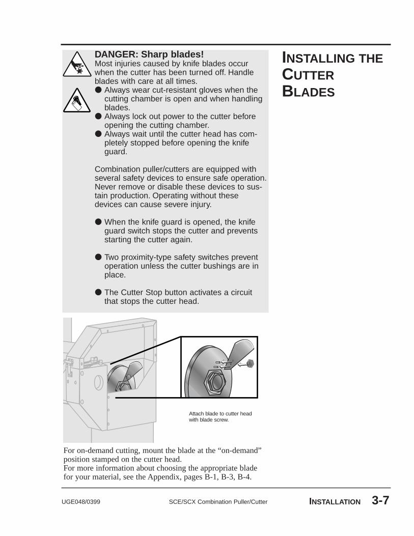
For on-demand cutting, mount the blade at the “on-demand”position stamped on the cutter head.For more information about choosing the appropriate bladefor your material, see the Appendix, pages B-1, B-3, B-4.
INSTALLING THECUTTERBLADES
DANGER: Sharp blades!Most injuries caused by knife blades occurwhen the cutter has been turned off. Handleblades with care at all times.● Always wear cut-resistant gloves when the
cutting chamber is open and when handlingblades.
● Always lock out power to the cutter beforeopening the cutting chamber.
● Always wait until the cutter head has com-pletely stopped before opening the knifeguard.
Combination puller/cutters are equipped withseveral safety devices to ensure safe operation.Never remove or disable these devices to sus-tain production. Operating without thesedevices can cause severe injury.
● When the knife guard is opened, the knifeguard switch stops the cutter and preventsstarting the cutter again.
● Two proximity-type safety switches preventoperation unless the cutter bushings are inplace.
● The Cutter Stop button activates a circuitthat stops the cutter head.
Attach blade to cutter headwith blade screw.

SCE/SCX Combination Puller/Cutter UGE048/03993-8 INSTALLATION
MOUNTING THECUTTERBUSHINGS
Rotate the cutter headuntil the blade is positionedin the gap between where the bushings go.
Slide the downstream bushing into position,positioning it up to and barely touching the blade (using afeeler gauge). NOTE: the blade should not be deflected.
Tighten the set screwagainst the flat side of thebushing to hold the bushing in position.
DANGER: Sharp blades!Always wear cut-resistant gloves when the cut-ting chamber is open and when handlingblades. Never open cutting chamber withoutlocking out the cutter power and waiting untilthe cutter head stops spinning.
1
2
3
UpstreamDownstream
For more information aboutsetting and adjusting the gapfor the bushings, see AboutCutter Bushings, in theAppendix, page C-1.
Location of set screws

UGE048/0399 SCE/SCX Combination Puller/Cutter INSTALLATION 3-9
Slide the upstream bushing into position,posi-tioning it up to but not touching the blade. Use feelergauge.
Tighten the set screwagainst the flat side of thebushing to hold the bushing in position.
Rotate the cutter head by handto make sure thebushings did not move, and the the blade still passesthrough the gap between the bushings.
4
5
6
MOUNTING THECUTTERBUSHINGS

SCE/SCX Combination Puller/Cutter UGE048/03993-10 INSTALLATION
Turn the main power disconnect to the off position.
Remove the upper and lower belt guards:
● Remove the screws attaching guards to unit (four each: top, bottom, front and rear).
● Disconnect the safety cable(on the upper guard).
● Lift off and remove guard.
ADJUSTINGBELT TENSION
1
2
Check belt tension. Use a tension-measuring tool.Belts should be just tight enough to prevent slipping,and the gap between the upper and lower belts should beeven across the width of the belt. NOTE: Loose belts result in belt and product slippage; over-tightenedbelts result in distorted product and can lead to prema-ture bearing failure.
3

UGE048/0399 SCE/SCX Combination Puller/Cutter INSTALLATION 3-11
Adjust belt tension, if necessary.Adjust tension by turning the threaded tension rods. Keeptension on front and back edges, top and bottom belts aseven as possible.
Fine tune tension:
● Lower the belts to a gap of about 1/8" (3 mm).(See Setting the Belt Gap, page 3-12.)
● From the upstream end of the belts, look downthe length of the belts at the gap between the belts.If the gap is not even, adjust the tension until thegap is even and measures 1/8”. The shape of the gapshould not be concave (over-tightened) or convex(too loose).
● Check tension and readjust as necessary.
4
5
SCE/SCX Combination Puller/Cutter UGE048/03993-12 INSTALLATION
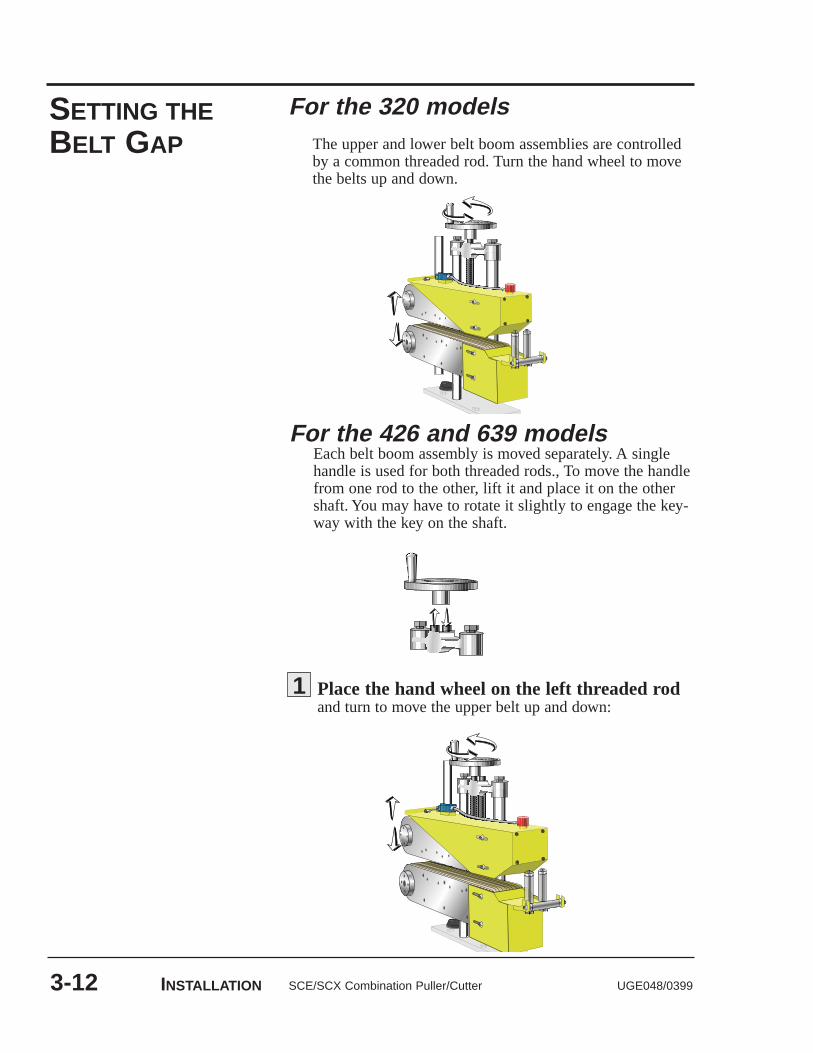
SETTING THEBELT GAP
For the 426 and 639 modelsEach belt boom assembly is moved separately. A singlehandle is used for both threaded rods., To move the handlefrom one rod to the other, lift it and place it on the othershaft. You may have to rotate it slightly to engage the key-way with the key on the shaft.
For the 320 modelsThe upper and lower belt boom assemblies are controlledby a common threaded rod. Turn the hand wheel to movethe belts up and down.
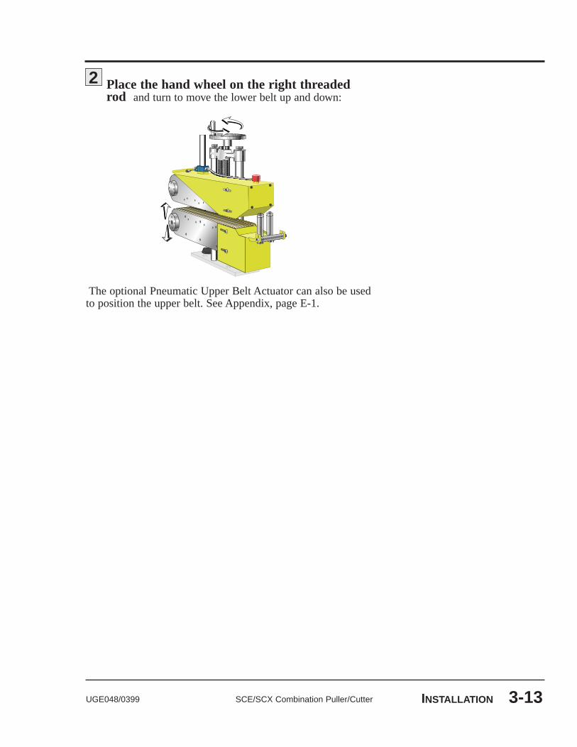
Place the hand wheel on the left threaded rodand turn to move the upper belt up and down:
1
UGE048/0399 SCE/SCX Combination Puller/Cutter INSTALLATION 3-13
The optional Pneumatic Upper Belt Actuator can also be usedto position the upper belt. See Appendix, page E-1.
Place the hand wheel on the right threadedrod and turn to move the lower belt up and down:
2

SCE/SCX Combination Puller/Cutter UGE048/03993-14 INSTALLATION
CHECKINGREPEATABILITY
Before any Conair puller/cutters are shipped, they are testedfor cut time repeatability to be sure they are within perfor-mance specifications. The repeatability test checks the perfor-mance of the rotary knife cutter to return the home park posi-tion after a complete cut. Acceptable repeatability timesallowed for each cutter model prior to shipping are:
Type of Cutter Repeatability Time
AC Pneumatic Cutter Less than 1 millisecondDC Pneumatic Cutter Less than 1.5 millisecondVelocity Servo (E Drive) Less than 1 millisecondPositional Servo (FX) Less than 0.1 millisecond
Note: 1-millisecond at 60 feet per minute is equal to .012 inches.
The repeatability mode is built into the Conair cutter controlsand allows you to perform similar tests, without any externaltest equipment. It is recommended that you check repeatabilityon a regular basis. Acceleration/deceleration delays of theservo do not contribute to repeatability error; any error isattributed solely to motor stability, couplings, assembly,power, and proximity sensor alignment. Use any blade speed and line speed. The line speed is onlyseen while in the Encoder or Product modes. It is recommend-ed that the tests be performed at cut intervals between 0.5 and5-seconds. Do not change the blade speed or the line speedafter starting the test.
To test repeatability:
Turn on the cutter. Performing the test with the cut-ter off-line shows problems with the cutter; performingthe test with the cutter on-line shows a problem with thepuller.
Place the cutter in any mode except followermode.
Press the Cut On/Off button; the cutter is activat-ed automatiocally.
Press and hold the Move Right buttonfor a minimum of 5 seconds.
Read the results on the display.
Repeat the test by pressing the Reset/Test Cut button to begina new sample period.
To end the Repeatability test, press any button except theReset/Test Cut button. The LED returns to its normal display.
1
2
3
5
4

UGE048/0399 SCE/SCX Combination Puller/Cutter INSTALLATION 3-15
REPEATABILITYTEST RESULTS
Results in Flywheel modeThe display shows "Repeat Test" and the park-to-park (PP)reading. This is the total (peak) variance of a full revolution ofthe cutter head. The reading is in milliseconds, to the thirddecimal place, i.e. 0.010 is 0.01 milliseconds (or 10 microsec-onds). If the reading exceeds 9.999 the unit automaticallyresets the repeatability test, displays "Over Run", and attemptsto begin the test again. If this occurs the error is too large andthere is a fault in the cutter drive that must be corrected.
Results in Timer modeWhen testing repeatability in Timer mode, the cutter is makingon-demand cuts at a set time interval (i.e. one-second inter-vals). The display shows "Repeat Test", and then the cut-to-park (CP) reading and the cut-to-cut (CC) reading. The read-ing is in milliseconds, to the third decimal place, i.e. 0.010 is0.01 milliseconds (or 10 microseconds).
CP is the peak time variance between the cut signal output(preset time) to the servo amplifier, and the proximity switchjust prior to the end of the cut cycle. This is the repeatabilityof the cutting system to return to the home park position. Thisvalue is higher than the PP reading since it includes the accel-eration and deceleration contributed by the servo motor.
CC is the peak time variance between cuts. Record and com-pare the cut-to-cut number to the CC value recorded inencoder or product mode shows how much error is by externalinfluences (i.e. variation in belt puller speed, encoder mount-ing problem, etc.).
If the reading exceeds 9.999, the unit automatically resets therepeatability test, displays the message "Over Run", andattempts to begin the test again. If this occurs the error is toolarge and there is a definite fault that must be corrected.
Results in Encoder or Product mode The display shows "Repeat Test", and then the cut-to-park(CP) reading and the cut-to-cut (CC) reading. The reading isin milliseconds, to the third decimal place, i.e. 0.010 is 0.01milliseconds (or 10 microseconds).
Compare the cut-to-park (CP) reading to the CP reading in theother modes. There should be very little difference in thesereadings.
Compare the cut-to-cut (CC) reading to the CC reading in theother modes. Since the Encoder and Product modes are influ-enced by external signals, this reading will reflect the speedstability of the puller.

SCE/SCX Combination Puller/Cutter UGE048/03993-16 INSTALLATION
The M-Trim control has about 55 programmable control para-meters. Some of these parameters are set by Conair as defaultvalues and others are set specifically for this combinationpuller/cutter.
The current value of each parameter is stored in memory andrecovered on startup. However, the M-Trim control's memorycan be corrupted by electrical noise, surges, etc, making itimpossible to retrieve the current values. While the control canbe reset to factory-default settings, any information specific toyour puller will be lost unless you maintain a copy of the cur-rent control parameter values. You must have this informationto return to normal operation. See Appendix, page F-1, PullerControl Settings, for the default settings and your particularsettings. Any time you change these settings, record them onthe Puller Control Settings page so you can easily reset yourcontrol. Some of the default codes are listed inside the flip-down cover of the control.
CHECKINGPROGRAMMINGVALUES
Turn on the puller by turning the main disconnect tothe ON position. The microprocessor performs a self-diagnostic test (about 2 seconds) then enters the defaultSTOP state:
Speed Command output = zero (Parameters and setpoints are recovered from mem-ory)
Open the controller's flip-down coverto view the programming keypad.
Press the Code Select button and enter the two-digit parameter code. Refer to Appendix, page F-1, PullerControl Settings, for a complete list of parameter codes,descriptions, and settings.
1
2
3

UGE048/0399 SCE/SCX Combination Puller/Cutter INSTALLATION 3-17
Press the Enter button.The two-digit parameter code displays in the lower LEDwindow. The current value for that code displays in theupper LED window.
For each parameter, compare the value in theupper display to the value listed on page F-1, Puller Control Settings, in the Appendix.
Continue to press the Enter button to view allthe parameter codes. If any values differ from what is list-ed on the Puller Control Settings page F-1, contact ConairService immediately.
4
5
6
PREPARING FORTESTING
Make sure all componentsare installed accordingto assembly drawings. Make sure that all bolts have beenchecked for tightness.
Check that the combination puller/cutter is firmly locked into position with the anchoring screws.
Check that all wiring conforms to electrical codes, and all wiring covers are in place.
1
2
3
DANGER: Pinch Hazard!Never remove or disable safety devices to sus-tain production. Operating without these devicescould lead to hazardous conditions that cancause severe injury. Take all necessary precau-tions when working around moving parts to pre-vent body parts and clothing from being pulledinto the machine.

SCE/SCX Combination Puller/Cutter UGE048/03993-18 INSTALLATION
TESTING THEINSTALLATION
Turn on the main disconnect. Plug in the main power cord and turn on the main disconnect. The dis-play should fully illuminate and perform its bootup routine.
Check that the E-Stop button is in the out,extended position. NOTE: If the E-Stop button is pushed in, the guardLED on the control will not illuminate, even if allother safety features are in the proper positions.
Press the Start button.The light on the button should light and the puller belts begin to rotate.
Make sure that the Cut On/Off LED is Off.If necessary, press button to turn off LED.
Press Start Cutter button. The LED in the buttonshould light. On SCX cutters, the cutter head will make one or two slow revolutions until it finds its home offset position.
Open the knife guard. The Machine Reset pushbutton should light.
If the cutter is not working properly at any time, turn it offimmediately and refer to the Troubleshooting section of thisUser Guide.
If you do not encounter any problems, proceed to theOperation section.
6
5
4
3
2
1

4-1UGE048/0399 SCE/SCX Combination Puller/Cutter
●● The Cutter Control . . . . . . . . . . . .4-2●● The Puller Control . . . . . . . . . . . . .4-3●● Cutter Control Features . . . . . . . .4-4●● Puller Control Features . . . . . . . .4-8●● Combination Control Features . . .4-9●● Before Starting . . . . . . . . . . . . . .4-10●● Powering Up . . . . . . . . . . . . . . . .4-11●● Programming the Puller Speed .4-12●● Setting the Blade Speed . . . . . . .4-12●● Choosing the Cutting Mode . . . .4-13●● Setting the Cutting Mode . . . . . .4-14●● Setting the Prescale Value . . . . .4-15●● Checking Cut Quality . . . . . . . . .4-16●● Starting the Puller/Cutter . . . . . .4-16●● Making Adjustments
During Operation . . . . . . . . . .4-17●● Making Large Changes
to the Puller Speed . . . . . . . . .4-17●● Fine-tuning the Puller Speed . . .4-18●● Making a Manual Cut . . . . . . . . .4-18●● Counting the Number of Cuts . .4-18●● Adjusting Prescale Values . . . . .4-19●● Temporarily Stopping Cutting . .4-19●● Stopping Only the Cutter . . . . . .4-19●● Stopping the Puller/Cutter . . . . .4-20●● Shutting Down the Puller/Cutter..4-20
OPERATION

SCE/SCX Combination Puller/Cutter UGE048/03994-2 OPERATION
THE CUTTERCONTROL
ADJUSTMENT BUTTONSchange preset length, scale fac-tor, cutting mode parameters andblade speed (SCX only).
CUTTER STATUS BUTTONSstart and stop the servo motor amplifier.Lights show you what is currently in use.
TOTAL ON/OFFcounts the numberof cuts.
RESET clears thecounter.
TOTAL displays mes-sages during startupand programming.
Length displays startupmessages, length, time, aswell as error messages.
CUT ON/OFFenables and dis-ables cutting.
Reset/Test zeros lengthand scale factors andcuts sample pieces.
CUT MODE BUTTONSlet you choose the cutting mode (list-ed above the Select button) and theblade speed (for the SCX) or thecomp (for SCE).
Detailed description of the Cutter Control begins on page 4-4.
UGE048/0399 SCE/SCX Combination Puller/Cutter OPERATION 4-3
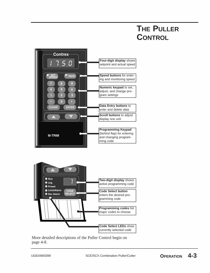
THE PULLERCONTROL
Numeric keypad to set,adjust, and change pro-gram settings
Speed buttons for enter-ing and monitoring speed
Scroll buttons to adjustdisplay one unit
Four-digit display showssetpoint and actual speed
Programming Keypad(behind flap) for enteringand changing program-ming code
Data Entry buttons toenter and delete data
Two-digit display showsactive programming code
Code Select buttonenters the desired pro-gramming code
Code Select LEDs showcurrently selected code
Programming codes listmajor codes to choose
More detailed descriptions of the Puller Control begin onpage 4-8.

CUTTERCONTROLFEATURES
SCE/SCX Combination Puller/Cutter UGE048/03994-4 OPERATION
The cutter control has several features that allow you to inputsetup information, monitor cutting process, and view errors.
Total information is located in the upper left of the control andconsists of:
● Total LED displays messages during startup and pro-gramming. During normal operation, it shows the numberof cuts if the counter has been activated. It also displayserror messages. See Troubleshooting, starting on page 6-1, for more details about error messages.
● Total On/Off button activates a counter that allows youto monitor the number of cuts. This button is ON whenthe LED in the corner is lit.
● Reset buttonclears the counter and resets count to zero.
Length information is located on the right of the control andconsists of:
● Length LED displays messages during startup. Duringprogramming, it shows the value of adjustable parameters.During normal operation, it shows either current length orelapsed time depending on the cutting mode. It also dis-plays error messages. See Troubleshooting for moredetails about error messages.
● Cut On/Off button enables/disables automatic cutting.
● Reset/Test button has several functions:
◆ It produces a sample cut during normal operation at the set blade speed while resetting the length count. (SCX model only). The cut piece is not counted onthe total counter.
◆ It sets the length and scale factor presets to zero in programming mode.
● Set button and Adjustment arrows are used to:
◆ Change preset length◆ Change preset scale factor◆ Change cutting mode parameters◆ Set blade amount (SCX Flywheel mode only)◆ Set blade speed (SCX only)

UGE048/0399 SCE/SCX Combination Puller/Cutter OPERATION 4-5
The adjustment arrows adjust some cutter parameters on adigit-by-digit basis:
Use the up Edit button to increase the values of the flashing digit. The digit steps one unit with each press (0 follows 9). This button can also be used to adjust cut length during normal operation.
Use down Edit button to decrease the value of the flashing digit. This button can also be used to adjust cut length during normal operation.
Use left Move button to select the digit to the left of the flashing digit. The new digit flashes, indicating it can be edited.
Use right Move button to select the digit to the right of the flashing digit. The new digit flashes, indicat-ing it can be edited.
NOTE:You must press the Set button first before thearrow buttons. Press the Set button again after using thearrow buttons to enter the new data.
The Cutter Status buttons and lights provide information aboutthe status of the cutting process:
● Start Cutter button enables the drive.
● Stop Cutter button disables the drive. NOTE: The servomotor amplifier is powered when the main disconnect isturned on. The cutter head cannot be rotated by hand untilthe machine has been electrically isolated.
The lights above these two buttons let you know the status ofthe cutter.
● Cut light lets you know when a cut output signal is gen-erated during an on-demand mode.
● Park light lights when the flag on the cutter head passesthe park sensor proximity switch or is given a signal froma simulated blade position that is generated by the drive.
● Motor light lights when the Start Cutter button is pushed.It lets you know the servo motor is enabled.
CUTTERCONTROLFEATURES

● Guard light lights when all safety devices (including theE-Stop and machine Reset buttons) are in the correctoperating positions.
● Encoder A, B lights indicate that the digital ring sensoron the puller motor is sensing signal changes.
The Cut Mode button and lights let you select the cut mode,see which cut mode the cutter is in, and set the blade speed(for the SCX only). They include:
● Select button lets you choose the cutting mode. Pressingthe button moves you through the list of available cuttingmodes. The cutting mode is active when the light next toit is lit.
● Timer light tells you the cutter is in the timer mode. Thetimer mode uses a timer to produce a cut signal. When apre-set time is reached, a signal activates a single cutcycle. In timer mode, accuracy depends on the consisten-cy of the belt puller or feeding device. If the speed of theextrudate changes, the length also changes.
● Product light tells you the cutter is in the product mode.Product mode uses an electric eye to sense the end of theextrudate and signal a cut. The electric eye is mountedeither on a bracket after the downstream cutter bushing,or on the discharge conveyor. If properly set up, this is themost accurate on-demand cutting mode.
● Encoder Mode light tells you the cutter is in the encodermode. Encoder Mode uses a digital encoder to produce aset number of counts per unit of measure of forwardextrudate movement. The cut signal is generated when thenumber of counts equal to the desired length is reached.
● Follower light tells you the cutter is in the follower mode.Follower mode (option available on SCX cutters only) isa continuous cutting mode that uses the capabilities of thepositional control servo motor. The operator enters thenumber of blades on the flywheel and enters the desiredcut length. The servo motor is then gearlocked to theencoder signal, which allows it to automatically speed upor slow down to follow the puller speed. Even if thepuller is being adjusted to change wall thickness or out-side diameter, the cut length remains constant.
SCE/SCX Combination Puller/Cutter UGE048/03994-6 OPERATION
CUTTERCONTROLFEATURES

UGE048/0399 SCE/SCX Combination Puller/Cutter OPERATION 4-7
● Flywheel light tells you the cutter is in the flywheelmode. Flywheel mode is a continuous cutting mode; theblade spins continuously. The speed is set at 750 rpm forSCE cutters but can be adjusted on SCX cutters (from200-750 rpm).NOTE: If the puller speed changes, the cut length willalso change. In most cases the puller speed consistencyhas a larger effect on cut length accuracy than the fly-wheel speed.
● Blade Speed button allows you to input the number ofblades on the cutter head and the cut length, and themicroprocessor determines the required cutter head speed(follower mode, SCX model only).
● Comp button is a non-functioning button (SCE modelonly).
CUTTERCONTROLFEATURES

PULLERCONTROLFEATURES
SCE/SCX Combination Puller/Cutter UGE048/03994-8 OPERATION
The puller control has several features that allow you to inputsetup information and monitor pulling process.
● Four-digit displayWhen programming the control, the four-digit display shows control settings when programming functions are used. During normal operation, it displays either setpoint or actual speed (tach). Both setpoint and actu-al speed are expressed as either linear speed (fpm or cm/min) or rpm.
● Speed buttonsUse the Set Speed button to enter and monitor the set-point speed. Pressing the Tach button displays the actualspeed. When you select one of these, the LED in the cor-ner lights. Either Set Speed or Tach is active at all times.NOTE: The actual speed shown is the average speed. It isupdated once every second.
● Numeric KeypadUse the numeric keypad to access control parameters,adjust programming settings and change the setpoint speed.
● Data Entry buttonsThe Clear button deletes the value showing on the digitaldisplay that you have just entered. The Enter button con-firms and accepts data values.
● Scroll buttonsUse the Up and Down scroll buttons to adjust the activesetpoint displayed on the digital display by one engineer-ing unit. These buttons are always enabled.
● Two-digit displayThe two-digit display shows the active programmingcode.
● Code Select buttonUse this button to enter the desired programming code.
● Code Select LEDsThe LED next to the code lights when that code is select-ed. These are not relevant when the Master Scaling for-mat is used.
● Programming codesThis table lists the major codes for you to choose. See Appendix, page F-1, for a complete listing of codes.

UGE048/0399 SCE/SCX Combination Puller/Cutter OPERATION 4-9
There are five buttons below the Cutter Control and the Pullercontrol. They are:
● Cutter Power On/OffTurn the Cutter Power On/Off to shut down the cut-ter portion of the combination for blade replace-ment, etc., without shutting down the puller portion.
● Machine Reset buttonUse to restart the combination puller/cutter after an emergency stop.
● E-Stop buttonPress to stop the Combination Puller/Cutter in an emergency.
● Puller Start buttonPressing this button energizes the puller portion.
● Puller Stop buttonPress this button to shut down the puller portion.
COMBINATIONCONTROLFEATURES

SCE/SCX Combination Puller/Cutter UGE048/03994-10 OPERATION
Before you start daily operation of the combination puller/cut-ter, you need to perform preventative maintenance. Necessarymaintenance is described in the Maintenance section of thisUsers Guide, beginning on page 5-1.
WARNING: Be sure that power to thepuller/cutter is OFF when doing any mainte-nance on the puller/cutter. Follow all safety ruleswhen performing any maintenance on thisequipment.
Daily maintenance includes:
● Inspecting the puller belt
● Inspecting the cutter blades
● Inspecting the blade mounting hardware
● Making sure the cutter bushings are properly secured
● Inspecting the closure latch on the knife guard
● Checking alignment with extrusion line
● Performing any floor lock adjustments as needed
These items and weekly, monthly, and semi-annual mainte-nance procedures are detailed in the Maintenance section ofthis User Guide.
BEFORESTARTING
DANGER: Pinch Hazard!Never remove or disable safety devices to sus-tain production. Operating without these devicescould lead to hazardous conditions that cancause severe injury. Take all necessary precau-tions when working around moving parts to pre-vent body parts and clothing from being pulledinto the machine.

POWERING UP
UGE048/0399 SCE/SCX Combination Puller/Cutter OPERATION 4-11
Plug in the power cord to restore power after any required maintenance.
Turn on the main power. The cutter control per-forms its bootup routine.
● The Total and Length displays show "Good day," followed by "LE-650" or "Servo" and EPROM ver-sion number, "Test good" (or an error if encoun-tered, i.e. "Length Error"), then "Set to" and the machine type (for SCE cutters) or servo version (for SCX cutters).
● The puller control performs RAM and PROM tests,then enters the default STOP state.
● At the end of the bootup routine the displays shows the current total count and the most recent length display.
While the cutter is booting up, perform the next three steps:
Make sure the E-Stop button is in the out,extended position.NOTE: If the E-stop is pushed in,the Guard light on the cutter control will not light, even ifall other safety features are in the proper positions foroperation.
Push the blue lighted machine Reset button(onthe control panel). The light should turn out.
NOTE: The blue Reset button lights any time power is disconnected, either by pushing the E-stop orturning off power using the disconnect. Thepuller/cutter won't run if the Reset button is lit.
Make sure that the Cut On/Off button is off(i.e. the light should not be lit). If necessary, press the button to turn the light off.
Press the green Puller Start button to start theservo motor amplifier program mode. The green light onthe Start Cutter button illuminates. On SCX cutters, theblade may make one or two rotations to find its home off-set position.
Press the green Start Cutter button to start theservo motor amplifier program mode. The red light on theStart Cutter button illuminates. On SCX puller/cutters, theblade may make one or two rotations to find its home off-set position.
1
3
6
4
5
2
You can watch the servomotor amplifier's statusscreen during bootup throughthe window on the back ofthe electrical enclosure. Thisdisplay gives information thatmay be useful if you have aproblem. See the Trouble-shooting section.
7
On SCX combination puller/cutters, the blade speed can beadjusted to suit your particular application. If you're not surewhat blade speed to use, start fast and work your way down toslower speeds. More information is available in the Appendix,pages B-1 through D-3.
To set the blade speed:
Press the Blade Speed button.NOTE: You can access blade speed ONLY when this button is ON. TheTotal LED displays the message "Blade." The Length dis-plays the previously set value; one of the digits is flash-ing.
Use the adjustment arrows to set the blade speedto the desired value. See Control Features, begin-ning on page 4-2, for an explanation of how to use thearrow keys.
Press either the Set button or the Blade Speed buttonto accept this value and return to normaloperation. Pressing either button has the same effect.
NOTE: If the value entered is outside the blade speed range for your cutter, the blade speed defaultsto either the maximum or the minimum.
SETTING THEBLADE SPEED
SCE/SCX Combination Puller/Cutter UGE048/03994-12 OPERATION
1
2
3
TIP: To find the minimum andmaximum blade speeds foryour particular cutter, firstenter a number under 100.The minimum blade speeddisplays as the default value.Record this number as theminimum blade speed foryour cutter. Next, enter anumber greater than 1000and record the resultingdefault value as the maximumblade speed.
After powering up the combination puller/cutter, you need toprogram the puller speed.
Press the Set Speed button. The numeric keypad isenabled.
Enter the desired setpoint (in fpm or rpm). The display shows the numbers you entered. If necessary,press the Clear button to delete any entry.
Press the Enter button. The control accepts the new setpoint and the puller goesto the new speed at a pre-programmed accelerttion rate.
1
2
3
PROGRAMMINGTHE PULLERSPEED

UGE048/0399 SCE/SCX Combination Puller/Cutter OPERATION 4-13
CHOOSE THECUTTING MODE
Choose on-demand modes (Timer, Encoder, Product) forlower-speed cutting and continuous modes (Flywheel orFollower) when making more than 350 cuts per minute.
● Timer Mode cuts based on time. When the preset time isreached, the cutter control signals the cutter head to rotateand make a cut. If the extrudate delivery speed changes,the length will also change.
● Encoder Modemonitors the forward movement of theextrudate and signals a cut based on a set number ofcounts per foot.
● Product Mode uses an electric eye to sense the end of theextrudate and signals a cut.
● Flywheel Mode is a continuous cutting mode; you set thespeed of the blade (available on SCX models only).
● Follower Mode (option available on SCX models only) isa continuous cutting mode. The servo motor automatical-ly speeds up or slows down to follow the puller speed.

SCE/SCX Combination Puller/Cutter UGE048/03994-14 OPERATION
Be sure that the Cut On/Off button is OFF.
Press the Select button to activate the cutting modeyou want. A mode is active when the LED next to it islit. Each time you press Select the control activates thenext available mode. Continue pressing the Select buttonuntil you get the mode you want. Then go on to the nextstep.
Make any additional entries required for the cutting mode you have selected. Press the Set button. Use the adjustment arrows to change the number listed onthe Length or Time display. Press Set button to return to normal operating mode.
● For Timer mode: Use the Set button andAdjustment arrows to change the time (in seconds,to three decimal places). NOTE: the decimal pointcannot be moved.
● For Encoder mode:Use the Set button andAdjustment arrows to change the cut length. If the cut length does not equal the set length, adjust theprescale value (see page 4-15).
● For Product mode: Use the Set button andAdjustment arrows to change the hold-off time. InProduct mode, the desired length is set by the elec-tric eye that sense the end and initiate a new cut. Toprevent unwanted double cuts, a hold-off (or one-shot) timer is built into the cutter control. After a cutis made, the hold-off time displays in the Displaywindow (in seconds, to three decimal places) andbegins counting down to zero. No cutting occursuntil the countdown is completed. Make sure thenew value is less than the time between cuts. NOTE:70-80% of the expected time between cuts is recom-mended.
● For Flywheel mode:Use the Set button and Adjustment arrows to change the cutter blade speed.If you are not sure what blade speed to use, start fast and work your way down to slower speeds. See Appendix: All About Cutter Blades, page B-1.
● For Follower mode: Press the Blade Speed button;use the Adjustment arrows to enter the number ofblades (1, 2, 4, or 8). Press the Set button to acceptthe value. Use the Set button and Adjustment arrowsto set the cut length.
SETTING THECUTTING MODE
12
3

SETTING THEPRESCALEVALUE
UGE048/0399 SCE/SCX Combination Puller/Cutter OPERATION 4-15
The Encoder mode uses a scale factor (called the prescalevalue) to compensate for configurations that differ from thestandard (a measuring wheel with a 1 foot circumference; a1200 pulse encoder; and English units of measure). Theprescale value is set at the factory for your equipment and typ-ical unit of measurement. However, it may occasionally benecessary to adjust the prescale value.
To check the length of the cut piece:
Use the Select button to choose the Encodermode.
Press the Set buttonand use the Adjustment arrowsto set the length equal to 12.00 inches.
Produce several trial cuts.Measure the length ofthese pieces to within your tolerance (usually to the near-est thousandth). If the pieces are not the correct length,you will have to change the prescale value.
NOTE: You can affect the cut length by changing theclamping force on the puller. Increasing the belt ten-sion results in less slippage and longer cut length.Decreasing belt tension results in more slippage andshorter cut lengths.
To adjust the prescale value:
Make sure you are in encoder mode,the CutterOn/Off is off, and the Start light is off.
Quickly press Set twice. The current prescale valuedisplays in the Display window. "Scale" displays in theTotal window.
Adjust the prescale valueusing the Adjustment arrows.
NOTE: the decimal place cannot be moved.
Continue adjusting and cutting pieces until thelength is within your requirements. The adjustmentprocess is done by trial and error.
NOTE: The cutter must be in the stop position to changethe prescale value.
Press the Set button. When all modes are set,press the Set button to accept the new values.
1
2
2
3
3
5
4
1

Press the Reset/Test button and observe the move-ment of the cutter blade. The cutter head makes a singlerotation and the blade moves through the cutter bushingswithout interference.
Insert a piece of extrudate through the cut-ter bushings.
Press the Reset/Test button.A single cut is madeat the preset blade speed. NOTE: this works even if CutOn/Off is off.
Inspect the cut. If necessary, adjust the blade designor blade speed (SCX only). See Appendix: All AboutCutter Blades, page B-1.
SCE/SCX Combination Puller/Cutter UGE048/03994-16 OPERATION
1
4
3
2
CHECKING CUTQUALITY
If you have not already done so, perform daily maintenancecheck, power up the puller/cutter, select cutting mode andblade speed (SCX only), and make a test cut to check cutquality.
Use the slide system to move the cutter as far from the pulleras possible:
Loosen the turnbuckle at the downstream end ofthe puller/cutter by turning 1-2 turns clockwise.
Slide the cutter as far downstream as it willgo.
Tighten the turnbuckle by turning it counterclock-wise.
When you are satisfied with cut quality, press the Cut On/Offbutton to illuminate the LED and begin automatic operation.
When the extrudate is running within tolerance, cut it with aknife or saw and feed it through the cutter bushings. Thenmove the cutter into position with respect to the puller:
● For flexible products, the cutter should be veryclose to the puller.
● For more rigid products, allow enough spacebetween the cutter and puller to absorb any shocgenerated during cutting.
STARTING THECOMBINATIONPULLER/CUTTER
1
2
3

UGE048/0399 SCE/SCX Combination Puller/Cutter OPERATION 4-17
You can make adjustments to the combination puller/cutterduring operation. These adjustments include:
● Making large changes to the puller speed
● Fine-tuning the puller speed
● Making a manual cut during operation
● Counting the number of cuts
● Adjusting the cutter preset values
● Temporarily stopping cutting
● Stopping only the cutter
Press the Tach button on the puller control. TheLED in the corner of the Tach button lights. The displayshows the actual puller speed, updated every 1-2 seconds.
Press the Set Speed button on the puller control.The LED in the corner of the Set Speed button lights. Thenumeric keypad is enabled.
Enter the desired setpoint (in fpm or rpm). If necessary, press the Clear button to delete any errors.
Press Enter to accept the new setpoint. The new setpoint is displayed.
MAKINGADJUSTMENTSDURINGOPERATION
1
2
3
MAKING LARGECHANGES TOTHE PULLERSPEED
4

SCE/SCX Combination Puller/Cutter UGE048/03994-18 OPERATION
COUNTING THENUMBER OF CUTS
Use the Up and Down arrows to adjust the setpoint. The set-point adjusts by one engineering unit each time an arrow ispressed.
◆ If the Tach button is active, the actual speed gradually changes to the new value.
◆ If the Set Speed button is active, the setpoint changes immediately.
NOTE: These keys are always enabled to change theactive setpoint. Because they provide only slow scrollspeeds, use them to make small changes to thepuller speed.
Perform a manual cut and reset the length by pressing theReset/Test button at any time during on-demand cutting.Pressing Reset/Test has no effect during continuous cutting.
Pressing Reset/Test when the Cut On/Off button is in the Offposition actuates a cut in flywheel and follower mode.
Count the number of cuts by pressing the Total On/Off button.Use the Reset button to return the count to zero. This featureis useful for collecting samples during a production run.
MAKING AMANUAL CUT
FINE-TUNINGTHE PULLERSPEED

UGE048/0399 SCE/SCX Combination Puller/Cutter OPERATION 4-19
Stop cutting temporarily by setting Cut On/Off to off. Thisallows you to view the cutting blade (through the window) orperform other tasks without shutting down the cutter.
TO STOPCUTTINGTEMPORARILY
ADJUSTINGCUTTER PRESETVALUES
You can shut down just the cutter portion of the combinationpuller/cutter if you need to change or adjust cutter blades:
Turn Cut On/Off dial to Off to stop cutting (light isoff).
Press Stop Cutter button to de-energize the cutterservo motor (light is off).
Turn Cutter Power On/Off to Off. Power is nolonger supplied to the cutter portion of the combinationpuller/cutter. The belt puller will continue running.
Follow the procedures on page 3-8 to change cutter blades.
1
2
3
STOPPING ONLYTHE CUTTER
Press the Set button and use the adjustment arrows to fine-tune a preset cutter value during normal operation:
● In Timer mode, adjust the time between cuts.● In Encoder and Follower modes,adjust the length.● In Product mode, adjust the hold-off time.● In Flywheel mode, adjust blade speed (SCX models only).
To use the Adjustment arrows:
● Count up one digit by pressing and releasing the Up Editadjustment arrow.
● Increase the preset more rapidlyby pressing and holdingthe Up Edit adjustment arrow.
● Count down one digit by pressing and releasing the DownEdit adjustment arrow.
● Decrease the preset more rapidly by pressing and hold-ing the Down Edit adjustment arrow.
When the arrow is released the display holds the preset for anadditional five seconds before returning to display the count inprogress. NOTE: While the control allows you to switch cut-ting modes during operation, this is not recommended.

To shut down the combination puller cutter, perform the stop-ping procedure listed above. No additional steps are necessaryif the combination puller cutter is shut down for short periodof time. If the unit is shut down for an extended period oftime, puller belts can and do acquire 'set.' If this occurs, let thepuller run for 20-30 minutes before use. This should removeany set from the belts.
SHUTTINGDOWN THEPULLER/CUTTER
Tto safely stop the combination puller/ cutter:
Press Cut On/Off button on the Cutter control tostop cutting (light is off).
Press Stop Cutter button to de-energize the servomotor (light is off).
Remove extrudate from both puller and cutter.
Press the red Puller Stop button.
Turn the rotary disconnect to the off position.
Disconnect the power cordif it is equipped with aplug on the end.
Lock out the rotary disconnect.
Clean the lubricant reservoir if you are shuttingdown the combination puller/cutter for the day.
WARNING: Never use any part of theguard circuit or the rotary disconnectto stop the combination puller/cutter.This can cause damage to the equipment andinjury to personnel. Use the recommended pro-cedure to assure safe stopping.
CAUTION: Always turn Cut On/Off toOff first.This is especially important in Flywheel mode;otherwise the blade may come to a stop in theextrudate.
WARNING: Never turn off the rotarydisconnect first.Doing so will turn off all power to the unit, andthe cutter will not be brought to a controlledstop. For safe stopping, always follow thesequence given above.
1
2
3
4
STOPPING THECOMBINATIONPULLER/CUTTER
6
78
SCE/SCX Combination Puller/Cutter UGE048/03994-20 OPERATION
5

5-1UGE048/0399 SCE/SCX Combination Puller/Cutter
●● Maintenance Features . . . . . . . .5-2●● Warnings and Cautions . . . . . . .5-2●● Preventative Maintenance
Schedule . . . . . . . . . . . . . . . . .5-4●● Inspecting Cutter Blades . . . . . .5-6●● Inspecting Blade Hardware . . . .5-6●● Inspecting Cutter
Bushing Screws . . . . . . . . . . .5-7●● Checking the Closure Latch . . .5-7●● Checking Floor Locks . . . . . . . .5-7●● Cleaning the Lubrication Tray . .5-8●● Lubricating the Slide Rail . . . . .5-8●● Checking the
Grease Locations . . . . . . . . . .5-9●● Adjusting the Cutter
Proximity Switches . . . . . . . .5-10●● Replacing Motor Brushes . . . .5-11●● Checking Electrical
Connections . . . . . . . . . . . . .5-12●● Testing Belt Tension . . . . . . . . .5-14●● Checking the Belt Gap . . . . . . .5-16●● Replacing Belts . . . . . . . . . . . .5-18●● Checking Torque . . . . . . . . . . .5-20
MAINTENANCE
WARNINGS ANDCAUTIONS
The Servo Cutter SCE and SCX models need regular, sched-uled maintenance for peak performance. Among the featuresthat require maintenance are:
● Puller belts● Cutter blades● Blade mounting hardware● Cutter bushings● The knife guard hardware● Floor locks● Lubrication ● Optional slide rail system● Electrical cables, terminals, and control lights● Equipment alignment
MAINTENANCEFEATURES
SCE/SCX Combination Puller/Cutter UGE048/03995-2 MAINTENANCE
To maintain the best performance of the Combination Puller/Cutter, it must be cleaned and inspected regularly.Maintenance includes a daily, weekly, quarterly, and semi-annual (every 6 months) schedule.
Use this maintenance schedule as a guide. You may need toshorten the time of the maintenance schedule, depending onhow often you use the servo cutter, and the types of materialflowing through it. Follow all precautions and warnings whenworking on the equipment.
WARNING: Improper installation,operation, or servicing may result inequipment damage or personal injury.This equipment should only be installed, adjust-ed, and serviced by qualified technical person-nel who are familiar with the construction, oper-ation, and potential hazards of this type ofmachine.
All wiring, disconnects, and fuses should beinstalled by qualified electrical technicians inaccordance with electrical codes in your region.
DANGER: Pinch Hazard!Never remove or disable safety devices to sus-tain production. Operating without these devicescould lead to hazardous conditions that cancause severe injury. Take all necessary precau-tions when working around moving parts to pre-vent body parts and clothing from being pulledinto the machine.
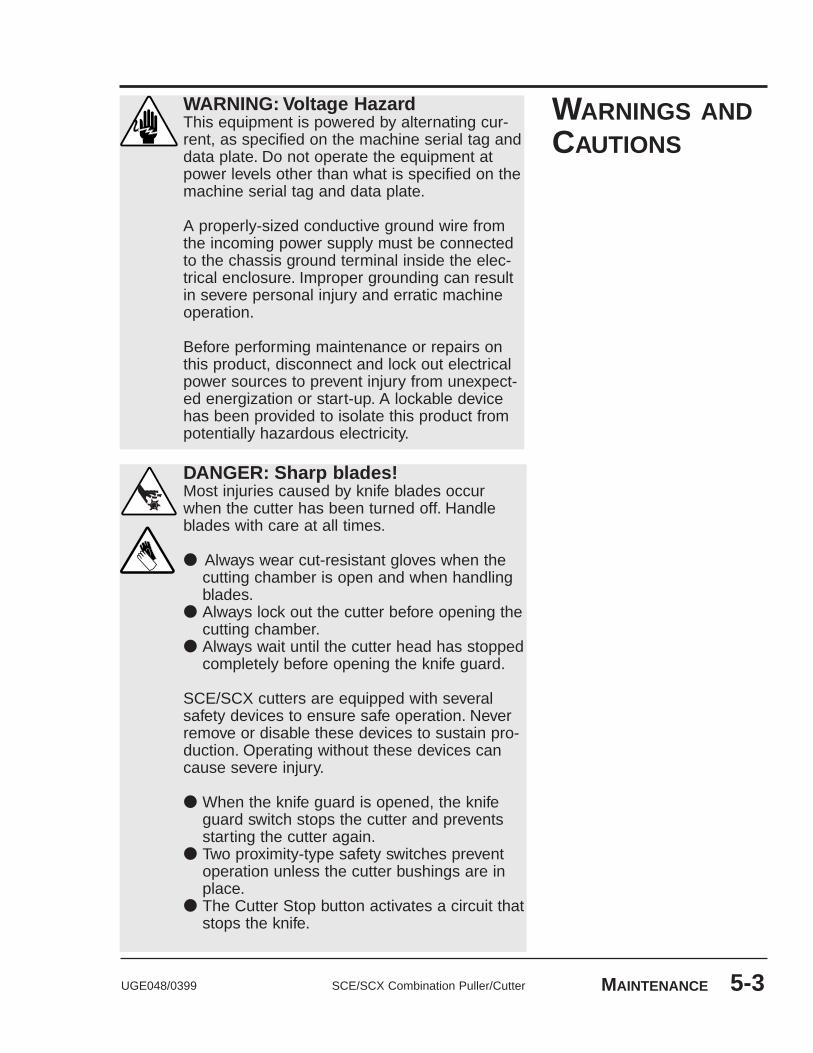
UGE048/0399 SCE/SCX Combination Puller/Cutter MAINTENANCE 5-3
WARNING: Voltage HazardThis equipment is powered by alternating cur-rent, as specified on the machine serial tag anddata plate. Do not operate the equipment atpower levels other than what is specified on themachine serial tag and data plate.
A properly-sized conductive ground wire fromthe incoming power supply must be connectedto the chassis ground terminal inside the elec-trical enclosure. Improper grounding can resultin severe personal injury and erratic machineoperation.
Before performing maintenance or repairs onthis product, disconnect and lock out electricalpower sources to prevent injury from unexpect-ed energization or start-up. A lockable devicehas been provided to isolate this product frompotentially hazardous electricity.
DANGER: Sharp blades!Most injuries caused by knife blades occurwhen the cutter has been turned off. Handleblades with care at all times.
● Always wear cut-resistant gloves when thecutting chamber is open and when handlingblades.
● Always lock out the cutter before opening thecutting chamber.
● Always wait until the cutter head has stoppedcompletely before opening the knife guard.
SCE/SCX cutters are equipped with severalsafety devices to ensure safe operation. Neverremove or disable these devices to sustain pro-duction. Operating without these devices cancause severe injury.
● When the knife guard is opened, the knifeguard switch stops the cutter and preventsstarting the cutter again.
● Two proximity-type safety switches preventoperation unless the cutter bushings are inplace.
● The Cutter Stop button activates a circuit thatstops the knife.
WARNINGS ANDCAUTIONS

SCE/SCX Combination Puller/Cutter UGE048/03995-4 MAINTENANCE
PREVENTATIVEMAINTENANCESCHEDULE
● Daily❒❒ Checking puller belts for wear
If a belt shows sign of cracks, tears, or other damage,replace it. Follow the steps on page 5-18.
❒❒ Checking puller belt tensionCheck the belt tension as described on page 5-14.
❒❒ Checking belt gapCheck the belt gap as described on page 5-16.
❒❒ Inspecting cutter blade(s) Clean, sharpen or replace as needed (see page 5-6).
❒❒ Inspecting the blade mounting hardwareCheck the blade-securing bolt and the holding pins(see page 5-6).
❒❒ Inspecting cutter bushing screwsCheck that the cutter bushing screws are secure (seepage 5-7).
❒❒ Checking the closure latch on the knife guardSee page 5-7.
❒❒ Inspecting unit alignmentProper alignment with other equipment on the line iscritical for optimum performance. Use a plumb line orlaser to check for a straight line from the extrusion dieto the cutter bushings.
❒❒ Checking floor locksSee page 5-7.
● Weekly❒❒ Cleaning the blade lubrication tray See page 5-8.❒❒ Lubricating shafts on slide rail system
See page 5-8.❒❒ Checking shafts and grease fittings
Lubricate all shafts and grease fittings as needed. Seepage 5-9.

PREVENTATIVEMAINTENANCESCHEDULE
UGE048/0399 SCE/SCX Combination Puller/Cutter MAINTENANCE 5-5
● Semi-annual (every six months)❒❒ Inspecting electrical terminals
Check all electrical terminals for tightness; adjust asneeded. See Checking Electrical Connections, page 5-12.
❒❒ Checking torque on Trantorque coupling deviceCheck the tightness (torque) of the Trantorque cou-pling device with a torque gauge. This device connectsthe cutter head to the Micron reducer shaft. SeeChecking Torque, page 5-20.
❒❒ Checking all electrical cablesInspect all electrical cables for cuts and abrasions.Replace as needed. Directions on page 5-12
❒❒ Inspecting control panel lightsCheck to make sure no LEDs or lights are burned outon the control panel. Replace as needed.
❒❒ Checking motor brushesInspect the motor burshes. Replace as needed. Seepage 5-11.
● Monthly❒❒ Checking hardware on the knife guard
Inspect the hardware on the knife guard (fasteners onhinge and the clear blade guard window). Tighten asneeded.
❒❒ Checking bushing holder proximity switchesInspect the proximity switch set screws. Adjust asneeded. See Adjusting the Cutter Proximity Switches,page 5-10.
❒❒ Cleaning the clear blade guard windowClean using glass cleaner or plain water. Other materi-als may cause premature loss of clarity or crazing.
❒❒ Checking the metal draw latchInspect the latch on knife guard for wear and propertension. Readjust or replace as needed.

INSPECTINGCUTTERBLADES
SCE/SCX Combination Puller/Cutter UGE048/03995-6 MAINTENANCE
Blades become dull over time depending on the material beingcut, cut rate, blade speed, and blade material and thickness.Check blades regularly for sharpness as well as scratches,nicks, burrs, and material buildup. Clean, sharpen or replaceas needed (see Installing Cutter Blades, page 3-8).
WARNINGDo not operate the combination puller/cutterwithout washers and blade-securing boltsecurely in place.
INSPECTINGBLADEHARDWARE
DANGER: Sharp blades!Most injuries caused by knife blades occurwhen the cutter has been turned off. Handleblades with care at all times.
● Always wear cut-resistant gloves when the cut-ting chamber is open and when handlingblades.
● Always lock out the cutter before opening thecutting chamber.
● Always wait until the cutter head has stoppedcompletely before opening the knife guard.
The blade-securing bolt should use both a lock washer and flatwasher, and be tightened enough to fully compress the lockwasher. Replace the holding pins if they appear worn.

UGE048/0399 SCE/SCX Combination Puller/Cutter MAINTENANCE 5-7
Check the latch and adjust it so the knife guard closes com-pletely. This prevents false triggering of the safety switch.
INSPECTINGCUTTERBUSHINGSCREWS
Check the set screws that secure the cutter bushings. If bush-ings move during cutting, cutting blades, and possibly thedrive chain, could be damaged.
CHECKING THECLOSURELATCH
It is best to remove the weight from the casters for optimumstability during cutting cycles. Check to see if the floor lock-ing mechanism is properly adjusted.
CHECKINGFLOOR LOCKS
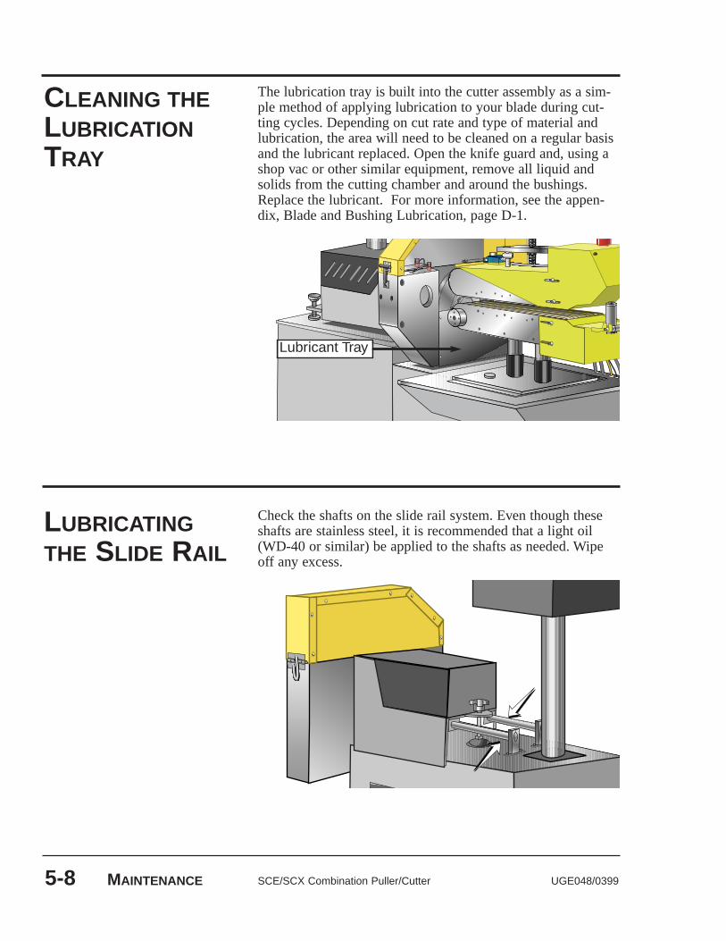
CLEANING THELUBRICATIONTRAY
SCE/SCX Combination Puller/Cutter UGE048/03995-8 MAINTENANCE
The lubrication tray is built into the cutter assembly as a sim-ple method of applying lubrication to your blade during cut-ting cycles. Depending on cut rate and type of material andlubrication, the area will need to be cleaned on a regular basisand the lubricant replaced. Open the knife guard and, using ashop vac or other similar equipment, remove all liquid andsolids from the cutting chamber and around the bushings.Replace the lubricant. For more information, see the appen-dix, Blade and Bushing Lubrication, page D-1.
LUBRICATINGTHE SLIDE RAIL
Check the shafts on the slide rail system. Even though theseshafts are stainless steel, it is recommended that a light oil(WD-40 or similar) be applied to the shafts as needed. Wipeoff any excess.
Lubricant Tray

UGE048/0399 SCE/SCX Combination Puller/Cutter MAINTENANCE 5-9
Lubricate all shafts and grease fittings as needed.
Use regular grease for alllocations except thread rods,vertical shafts, and verticalshaft drive boxes.
For thread rods and verticalshafts, use Never-Seize orequivalent.
The vertical shaft drive boxesrequire a high-temperaturegrease. Use Mobilgrease 28or equivalent.
CHECKINGGREASELOCATIONS
Lower bearinggrease fitting

SCE/SCX Combination Puller/Cutter UGE048/03995-10 MAINTENANCE
ADJUSTING THECUTTERPROXIMITYSWITCHES
Follow all warnings and cautions listed at the beginning of theMaintenance section of this User Guide.
Be sure the main power is disconnectedand thecutter is locked out.
Loosen the set screws that hold the cutter bushings.
Remove the cutter bushings.
Check the depth of the proximity switchface for each bushing. It should be recessed no more than 0.010 inches, but should not interfere with the bushingsthemselves.
Use an Allen wrench to check the tightnessof each proximity switch's retaining screw. NOTE: You can damage the proximity switch if youover-tighten the retaining screw.
Replace cutter bushingsand check for proper cut-ting blade alignment. See page 3-9, Mounting the CutterBushings, and the Appendix, pages C-1 to D-3.
Plug in the power cord and turn the main powerdisconnect to the on position if all other maintenance iscompleted.
2
1
3
4
6
7
5
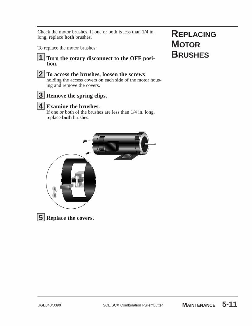
UGE048/0399 SCE/SCX Combination Puller/Cutter MAINTENANCE 5-11
REPLACINGMOTORBRUSHES
Check the motor brushes. If one or both is less than 1/4 in.long, replace both brushes.
To replace the motor brushes:
Turn the rotary disconnect to the OFF posi-tion.
To access the brushes, loosen the screws holding the access covers on each side of the motor hous-ing and remove the covers.
Remove the spring clips.
Examine the brushes.If one or both of the brushes are less than 1/4 in. long,replace both brushes.
Replace the covers.5
1
4
2
3

SCE/SCX Combination Puller/Cutter UGE048/03995-12 MAINTENANCE
Be sure the main power is disconnected and the cutter is locked out. Always disconnect and lock out the main power source before opening the unit or servicing.
Turn the main power disconnect to the off position before opening the electrical enclosure on theback of the cutter, or the back of the control. This is asafety device to prevent you from opening the doors if thepower is still on.
CHECKINGELECTRICALCONNECTIONS
WARNING: Electrical hazardBefore performing any work on this product,disconnect and lock out electrical powersources to prevent injury from unexpected ener-gization or start-up. A lockable device has beenprovided to isolate this product from potentiallyhazardous electricity.
WARNING: Improper installation, oper-ation, or servicing may result inequipment damage or personal injury.This equipment should only be installed, adjust-ed, and serviced by qualified technical person-nel who are familiar with the construction, oper-ation, and potential hazards of this type ofmachine.
All wiring, disconnects, and fuses should beinstalled by qualified electrical technicians inaccordance with electrical codes in your region.Always maintain a safe ground. Do not operatethe equipment at power levels other than whatis specified on the machine serial tag and dataplate.
1
2
Main power safety disconnect
UGE048/0399 SCE/SCX Combination Puller/Cutter MAINTENANCE 5-13
Open the electrical enclosure.
Inspect all wires and connections. Look for loosewires, burned contacts, and signs of over-heated wires.Have a qualified electrician make any necessary repairs orreplacements.
Close the electrical enclosure door.
Inspect the exterior power cords.Cords shouldnot be crimped, exposed, or rubbing against the frame. Ifthe main power cord runs along the floor, make sure it isnot positioned where it could rest in pooling water orcould be run over and cut by wheels or casters.
3
4
56

SCE/SCX Combination Puller/Cutter UGE048/03995-14 MAINTENANCE
Turn the main power disconnect to the offposition.
Remove the upper and lower belt guards:
● Remove the screws attaching guards to unit (foureach: top, bottom, front and rear).
● Disconnect the safety cable (upper guard).
● Lift off and remove guard.
TESTING BELTTENSION
1
2
Check belt tension. Use a tension-measuring tool.Belts should be just tight enough to prevent slipping, andthe gap between the upper and lower belts should be evenacross the width of the belt.
NOTE: It is important to have the proper belt ten-sion. Loose belts result in belt and product slippage;over-tightened belts result in distorted product andcan lead to premature bearing failure.
3

UGE048/0399 SCE/SCX Combination Puller/Cutter MAINTENANCE 5-15
Adjust belt tension, if necessary.Adjust tension by turning the threaded tension rods. Keep tension on front and back edges, top and bottom belts as even as possible:
4
Fine tune tension:
● Lower the belts to a gap of about 1/8" (3 mm).(See Adjusting Belt Gap, page 3-12.)
● From the upstream end of the belts, look downthe length of the belts at the gap between the belts.If the gap is not even, adjust the tension until thegap is even and measures 1/8”. The shape of the gapshould not be concave (over-tightened) or convex(too loose).
● Check tension and readjust as necessary.
5
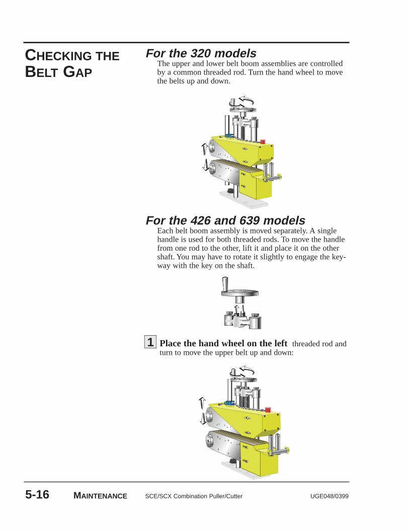
SCE/SCX Combination Puller/Cutter UGE048/03995-16 MAINTENANCE
CHECKING THEBELT GAP
For the 426 and 639 modelsEach belt boom assembly is moved separately. A singlehandle is used for both threaded rods. To move the handlefrom one rod to the other, lift it and place it on the othershaft. You may have to rotate it slightly to engage the key-way with the key on the shaft.
For the 320 modelsThe upper and lower belt boom assemblies are controlledby a common threaded rod. Turn the hand wheel to movethe belts up and down.
Place the hand wheel on the left threaded rod andturn to move the upper belt up and down:
1

UGE048/0399 SCE/SCX Combination Puller/Cutter MAINTENANCE 5-17
The optional Pneumatic Upper Belt Actuator can also be usedto position the upper belt. Refer to page E-1 in the Appendixfor more information.
Place the hand wheel on the right threadedrod and turn to move the lower belt up and down:
2
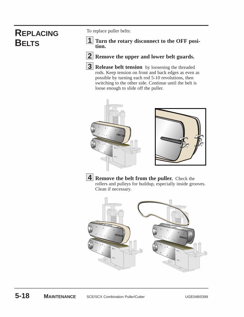
SCE/SCX Combination Puller/Cutter UGE048/03995-18 MAINTENANCE
To replace puller belts:
Turn the rotary disconnect to the OFF posi-tion.
Remove the upper and lower belt guards.
Release belt tension by loosening the threaded rods. Keep tension on front and back edges as even as possible by turning each rod 5-10 revolutions, then switching to the other side. Continue until the belt is loose enough to slide off the puller.
1
23
Remove the belt from the puller.Check therollers and pulleys for buildup, especially inside grooves.Clean if necessary.
4
REPLACINGBELTS

UGE048/0399 SCE/SCX Combination Puller/Cutter MAINTENANCE 5-19
Reverse the process to install the new belt. Make sure ribs inside the belt fit properly into grooves,and keep tension on front and back sides as even as possi-ble by alternating between the two threaded rods.
Adjust belt tension and belt gap. Follow the stepson pages 5-14 through 5-17.
5
6

SCE/SCX Combination Puller/Cutter UGE048/03995-20 MAINTENANCE
The Trantorque coupling device connects the servo motor tothe cutter head. It is important that it is tightened to the propertorque.
Carefully remove the cutter blade.
Check to make sure both the shaft and com-ponent bore of the Trantorque coupling device arecompletely free of paint, grease, oil, and dirt. If necessary,clean the surfaces with a non-petroleum based solvent,such as isopropyl alcohol.
Use a torque wrenchto make sure the nut is tight-ened to the proper installation torque (2000 in-lb or 225N-m). Do not overtighten; it can cause damage to theunit.
CHECKINGTORQUE
WARNING: No lubricants!Do NOT use lubricants on the Trantorque cou-pling device.
12
DANGER: Sharp blades!Always wear cut-resistant gloves when the cut-ting chamber is open and when handlingblades. Never open cutting chamber withoutlocking out the cutter power and waiting untilthe cutter head has stopped completely. Handleblades with care at all times.
3
6-1UGE048/0399 SCE/SCX Combination Puller/Cutter
●● Before Beginning . . . . . . . . . . . .6-2●● A Few Words of Caution . . . . . .6-2●● Identifying the
Cause of a Problem . . . . . . . . .6-4●● Puller Operation Problems . . . .6-5●● Cutter Operation Problems . . . .6-7●● Product Quality Problems . . . .6-11
REPAIR●● Restoring Default
Memory Settings . . . . . . . . . .6-16●● Restoring User-Specific
Memory Settings . . . . . . . . . .6-16●● Replacing Safety and
Proximity Switches . . . . . . . .6-17●● Checking the
Servo Amplifier . . . . . . . . . . .6-18●● Adjusting the
Proximity Switches . . . . . . . .6-18●● Checking the Motor/
Reducer Assembly . . . . . . . . .6-19●● Testing Repeatability . . . . . . . .6-20●● Results of Repeatability
Testing . . . . . . . . . . . . . . . . . .6-21
TROUBLESHOOTING

BEFOREBEGINNING
SCE/SCX Combination Puller/Cutter UGE048/03996-2 TROUBLESHOOTING
A FEW WORDSOF CAUTION
WARNING: Improper installation, oper-ation, or servicing may result inequipment damage or personal injury.This equipment should only be installed, adjust-ed, and serviced by qualified technical person-nel who are familiar with the construction, oper-ation, and potential hazards of this type ofmachine.All wiring, disconnects, and fuses should beinstalled and adjusted by qualified electricaltechnicians in accordance with electrical codesin your region. Always maintain a safe ground.Do not operate the equipment at power levelsother than what is specified on the machineserial tag and data plate.
WARNING: Electrical hazardBefore performing maintenance or repairs onthis product, disconnect and lock out electricalpower sources to prevent injury from unexpect-ed energization or start-up. A lockable devicehas been provided to isolate this product frompotentially hazardous electricity.
You can avoid most problems by following the recommendedinstallation, operation and maintenance procedures outlined inthis User Guide. If you have a problem, this section will helpyou determine the cause and tell you how to fix it.
Before you begin troubleshooting:
❒ Find any wiring, parts, and assembly diagrams that were shipped with your equipment. These are the best reference for correcting a problem. The diagrams will note any custom features or options not covered in thisUser Guide.
❒ Verify that you have all instructional materials related to the puller. Additional details about troubleshooting and repairing specific components are found in these materials.
❒ Check that you have manual for other equipment con-nected in the system. Troubleshooting may require investigating other equipment attached to, or connectedwith the puller.

UGE048/0399 SCE/SCX Combination Puller/Cutter TROUBLESHOOTING 6-3
DANGER: Sharp blades!Most injuries caused by knife blades occurwhen the cutter has been turned off. Handleblades with care at all times.
● Always wear cut-resistant gloves when thecutting chamber is open and when handlingblades.
● Always lock out power to the cutter beforeopening the cutting chamber.
● Always wait until the cutter head has stoppedcompletely before opening the knife guard.
Combination puller/cutters are equipped withseveral safety devices to ensure safe operation.Never remove or disable these devices to sus-tain production. Operating without these devicescan cause severe injury.
● When the knife guard is opened, the knifeguard switch stops the cutter and preventsstarting the cutter again.
● Two proximity-type safety switches preventoperation unless the cutter bushings are inplace.
● The Stop button activates a circuit that stops the knife.
A FEW WORDSOF CAUTION

IDENTIFYING THECAUSE OF APROBLEM
SCE/SCX Combination Puller/Cutter UGE048/03996-4 TROUBLESHOOTING
The Troubleshooting section covers problems directly relatedto the operation and maintenance of the CombinationPuller/Cutter. This section does not provide solutions to prob-lems that originate with other equipment. Additional trou-bleshooting help can be found in manuals supplied with theother equipment.
The main problems you will see with the CombinationPuller/Cutters are:
● Puller operation problems, which focus on problemsthat are clearly related to the pullers mechanical compo-nents and electrical control system.
● Cutter operation problems, which focus on problemsthat are clearly related to the operation of the cutter’smechanical components and electrical control system.
● Product quality concerns. Extrudate quality problemsmay be related to Combination Puller/Cutter operation.Of course, other sections of the extrusion line also influ-ence the quality of the extruded product. This sectiondoes not provide solutions to problems originating withother equipment on the extrusion line.
Additional troubleshooting help can be found in the documen-taion manuals included with this User Guide.

PULLEROPERATIONPROBLEMS
UGE048/0399 SCE/SCX Combination Puller/Cutter TROUBLESHOOTING 6-5
Look in this section when either the puller control or motor isnot working properly.
Symptom◆ The puller‘creaks’ while run-ning.
◆ The puller doesnot start.
◆ Controllerstopped duringpower-up PROMtest. ‘❐❐.❐❐.❐❐.❐❐’ dis-plays in the digitaldisplay.
◆ Controllerstopped duringpower-up RAMtest. A number dis-plays in the digitaldisplay.
◆ Motor does notstop.
◆ Motor does notrun.
Possible causeThe belt is too tight.
The bearings are failing.
The E-stop button ispushed in.
RAM failed.
PROM checksum com-parison failed.
SolutionCheck the belt tension; loosenif necessary. See Maintenancesection, page 5-14.
Replace the bearings.
Pull out the E-stop button.(Make sure it clicks into posi-tion.)
Contact Conair service.
Contact Conair service.
Check programming code 53.Refer to M-Trim User Manual,chapter 9.
Check programming code 53.Refer to M-Trim User manual,chapter 9.

Symptom◆ Motor runs atwrong speed.
◆ Motor at correct(set) speed, but notfast enough for theextrusion line.
◆ Motor at correct(set) speed, but notslow enough of theextrusion line.
◆ Motor seemsunstable.
◆ Tach readsincorrectly.
◆ Display shows ---1, ---2, or ---3.
SCE/SCX Combination Puller/Cutter UGE048/03996-6 TROUBLESHOOTING
Possible cause
Maximum rpm incorrect-ly set.
Minimum rpm incorrect-ly set.
Electrical noise is reach-ing controller.
SolutionRefer to M-Trim user manual,chapter 9.
Check programming code 11.Refer to M-Trim user manual,chapter 9.
Check programming code 10.Refer to M-Trim user manual,chapter 9.
Check PID tuning. SeeAppendix, page F-3.
Refer to M-Trim user manual,chapter 9, item 8.
Check control parametersagainst desired values. If val-ues have changed, restore theoriginal settings. See RestoringMemory Settings. page 6-15.
PULLER OPERATIONPROBLEMS, CONT’D

CUTTEROPERATIONPROBLEMS
UGE048/0399 SCE/SCX Combination Puller/Cutter TROUBLESHOOTING 6-7
Look in this section when the cutter control is not workingproperly.
Symptom◆ The lightedReset button doesnot go out whenpressed.
◆ Pressing StartCutter had noeffect. The LED inthe corner does notlight and “GuardError” displays.
◆ Pressing theReset/Test buttondoes not produce acut when in an on-demand mode.
Possible causeThe E-stop button ispushed in.
Guard light not illumi-nated.
A safety switch has failed.
There is a loose connec-tion.
The relay is bad.
The guard circuit failed.
The servo amplifier is notin Program mode.
There is a loose connec-tion.
SolutionPull out the E-stop button.
Check to see if:
❒ The blade guard is closed. ❒ Master Control relay
(MCR) has failed. Replacerelay.
Check connections and replaceif needed.
Check wiring between cuttercontrol and the relay.
Repair or replace the relay.
Check guard circuit, repair orreplace components.
Check servo amplifier LEDdiagnostic display.The letter Pshould be visible. If not,reboot main power.
Check wiring and tighten con-nection.

SCE/SCX Combination Puller/Cutter UGE048/03996-8 TROUBLESHOOTING
Symptom◆ After pressingStart Cutter, thecutter head rotatesslowly but does notstop (SCX only).
◆ Guard LED oncutter does not illu-minate.
◆ Encoder A, BLEDs do not light.
Possible causeThe Blade Home proxim-ity switch failed or theconnection to it is loose.
Guard circuit is open.
Input from encoderfailed.
Encoder failed.
SolutionCheck connections and replaceswitch if needed.
Check to see if:
❒ The blade guard is closed.❒ Loose connection to guard
circuit. Tighten connec-tion.
❒ Guard switch is bad. Replace switch.
Check encoder cable for conti-nuity. Connect any loose wires.
Replace encoder.
CUTTER OPERATIONPROBLEMS, CONT’D
UGE048/0399 SCE/SCX Combination Puller/Cutter TROUBLESHOOTING 6-9
Symptom◆ In encoder ortimer modes, thedisplay shows thecount which resets,but a cut does notoccur at the pointof reset.
◆ Cutter controldisplays “Bladeerror”.
◆ Cutter controldisplays “Bladeerror”.
Possible causeThere is a problem with thecutter control.
There is a problem with theservo amplifier.
There is a loose connection.
There is an anti-jam circuitsignal.
There is a problem with thehome proximity switch.
There is a problem in theguard circuit.
SolutionCheck for control output.
See Checking the ServoAmplifier.
Check wiring for loose connec-tions.
This error appears when theblade does not go through thecut cycle in the required time.
Check for:❒ Loose connection on cutter
control or servo amplifier. ❒ Fault on Amplifier prevent-
ing cut cycle. ❒ Blade is stuck in extrudate/
bushings.
See Adjusting the ProximitySwitches, page 6-17.
Make sure the E-stop andReset buttons are in the correctoperating positions. Checkguard circuit for loose connec-tions or bad switches. Replaceif necessary.
CUTTER OPERATIONPROBLEMS, CONT’D

CUTTER OPERATIONPROBLEMS, CONT’D
SCE/SCX Combination Puller/Cutter UGE048/03996-10 TROUBLESHOOTING
Symptom◆ Blade speed doesnot change when newspeed is entered intothe control (SCXonly).
◆ Cutter mode selec-tion does not changecut mode.
◆ The park (home)position is drifting,i.e. the blade parksfurther away fromthe original parkposition (SCX only).
◆ The park positionis erratic (SCE only)
Possible causeThere is a communicationfailure between the con-trol and drive.
There is a communicationfailure between the con-trol and drive.
The coupling between theservo motor and theMicron reducer hasslipped.
The Trantorque couplinghas slipped.
The home proximityswitch is bad.
The home proximityswitch is not properlygapped.
SolutionCheck wiring for loose con-nections and tighten.
Check wiring for loose con-nections and tighten.
See Checking the Motor/Reducer Assembly, page 6-19.
Refer to the Trantorqueinstructions, page 5-20.
Replace the proximity switch.
See Adjusting the ProximitySwitches, page 6-17.

PRODUCTQUALITYPROBLEMS
Look in this section when the final product does not meetquality standards.
UGE048/0399 SCE/SCX Combination Puller/Cutter TROUBLESHOOTING 6-11
Symptom◆ Annular ringspresent on theextrudate.
◆ Burrs at cut site.
Possible causeThe belt puller is tooclose to the cutter.
The anti-backlash bear-ings are not workingproperly.
The bushings do not pro-vide enough support dur-ing cutting.
The bushing gap is toowide.
The blade speed is toolow.
The blade is too thick.
SolutionIf the extrudate is interrupted(stopped during processing),annular rings can develop,especially on a thin-walledproduct. Slightly increase thedistance between the puller andthe cutter, and test the productuntil the distance is correct.
Stop the puller and try to movethe lower belt by hand. Thelower belt should not be able totravel backwards when you tryto move it. If it does, the anti-backlash bearings must bereplaced. Contact ConairService.
Change bushing design to makemore supportive.
Check that bushing gap is0.001-0.003 in. larger thanblade. Adjust if necessary.
Increase blade speed ordecrease the cut path area.
Use a thinner blade or add heatto extrudate.

SCE/SCX Combination Puller/Cutter UGE048/03996-12 TROUBLESHOOTING
Symptom◆ Hairs or strings.
Possible causeBlade speed is too low.
The blade is too thick.
The blade is wrong forthe application.
Material is building upon the blade and wipingoff on the cut site.
There are imperfectionson the blade.
A hole or slot in the bladecut path is causing a‘cheese grater’ effect.
The extrudate is too cold.
SolutionIncrease the blade speed ordecrease the blade cut patharea (blade width).
Excessive blade thickness cancause frictional heat. Use athinner blade.
Change angle of the bladeattack or the blade style todecrease the cut path area.
Use blade lubrication (water,etc.) or change lubricants. SeeAppendix, page D-1. Considera blade wiping system.
The cutting edge should nothave grind marks, burrs orother imperfections. Check theblade and replace if necessary.
Change to a different bladedesign. See pages B-1 throughB-6.
If the extrudate is too cold, itcan fracture during cutting.Raise the extrudate's tempera-ture.
PRODUCT QUALITYPROBLEMS, CONT’D

UGE048/0399 SCE/SCX Combination Puller/Cutter TROUBLESHOOTING 6-13
Symptom◆ Cracks at cutsite.
Possible causeThe extrudate is too cold.
The blade speed is toohigh.
The bushings are not pro-viding enough supportduring cutting.
The cutting blade is toosharp.
If using Nylon, it may becooling too quickly.
SolutionIf the extrudate is too cold, itcan fracture or whiten duringcutting. Raise the extrudate'stemperature.
High blade speeds can causetoo much impact. Lower theblade speed.
Change the bushing design tomake them more supportive.
A blade that is too sharp canfracture some materials, espe-cially rigid PVC and nylons.Slightly dull the blade.
If nylon is cooled too quickly,its molecular structure maybecome unstable, leading topoor physical properties. Trymore gradual cooling.
PRODUCT QUALITYPROBLEMS, CONT’D

Symptom◆ Cut is not square.
Possible causeThe blade speed is toolow.
The blade is misaligned.
The cutter bushings arenot properly gapped.
The knife bevel is notsymmetric.
For rigid products thepuller is too close to thecutter.
SolutionLow blade speeds can causeexcessive blade interruption.Increase blade speed ordecrease the blade cut patharea.
Check that blade is 90 degreesrelative to the bushing holder.
If the cutter bushings are notproperly gapped, the blademay be free to move with theextrudate. Check and adjust ifnecessary. See pages 3-9 andC-1.
If the knife bevel is asymmet-ric, the blade will tend to movein the direction of the smallerbevel. Be sure that the bevel issymmetric. NOTE: You canuse this to your advantage withsome rigid products.
There must be enough spacebetween the puller and cutterto allow for the extrudate tostop during cutting.
SCE/SCX Combination Puller/Cutter UGE048/03996-14 TROUBLESHOOTING
PRODUCT QUALITYPROBLEMS, CONT’D

PRODUCT QUALITYPROBLEMS, CONT’D
UGE048/0399 SCE/SCX Combination Puller/Cutter TROUBLESHOOTING 6-15
Symptom◆ Length of cut isincorrect.
Possible causeRepeatability is wrong.
Encoder, input deviceproblem.
There is a problem withthe puller.
SolutionTest for repeatability. Seepages 6-20 and 6-21.
Check encoder, input deviceand clean. Run repeatabilitytest (see pages 6-20 and 6-21).
Run repeatability test (seepages 6-20 and 6-21).

SCE/SCX Combination Puller/Cutter UGE048/03996-16 TROUBLESHOOTING
To restore default memory settings:
Turn OFF power to the puller.
While simultaneously pressing the Clear and the7 on the numeric keypad, turn the power ON.
◆ The factory default settings are restored. The M-Trim control performs the power up routinedescribed in the Operation section, Powering Up,page 4-9.
Set any user-specific memory settings after you have restoredthe default memory settings. Using the Puller Control Settingsfound on the tables on pages F-1 and F-2 restore your controlto it’s normal operating state:
Open the flap at the bottom of the M-Trim control.
Press the Control Select button.
Enter the desired two-digit code number (from the tables on pages F-1 and F-2).
Press the Enter button.
◆ The two-digit code displays in the lower digital dis-play.
◆ The current parameter value displays in the upperdigital display.
◆ The numeric keypad is enabled.
If necessary, use the numeric keypad to enter a new value.
RESTORINGDEFAULTMEMORYSETTINGS
WARNINGThis procedure restores the M-Trim control tothe factory default settings. Any user-enteredparameters or programming will be erased.
12
1
RESTORINGUSER-SPECIFICMEMORYSETTINGS
23
4
CAUTIONPress the Enter button within 10 seconds toaccept the new number. Otherwise the parame-ter reverts to the previous value.

UGE048/0399 SCE/SCX Combination Puller/Cutter TROUBLESHOOTING 6-17
REPLACINGSAFETY ANDPROXIMITYSWITCHES
Three safety switches are included in SCE/SCX cutter sec-tions: a keyed safety switch on the knife guard, and a proximi-ty switch on each cutter bushing. A failure in any of theseswitches prevents the puller/cutter from running.
● Safety Switch
If you suspect a problem with the keyed safety switch onthe knife guard, check for loose or damaged wires.Replace the switch if wires appear to be undamaged.
● Proximity Switches
The proximity switches on the cutter bushings have LEDsthat light when the bushing is sensed. If an LED does notlight when the bushing is in place:
Check for loose or damaged wires.
Remove the cutter bushingand make sure theproximity switch is properly positioned, i.e. 0.010"from the bushing surface.
Remove the proximity switch by loosening the setscrew. Test it by bringing an object close to the sen-sor when the power is turned on. If the LED does notlight, replace the proximity switch.
1
2
3

The home position proximity switch should be 0.010" fromthe 5/16” thread rod on the cutter head for proper operation.
Open the knife guard.
Locate the 1/4" thread rod on the cutter head.It should be 0.010" from the proximity switch sensorwhen it passes that location. If necessary, loosen the jamnuts, readjust the distance, and re-tighten the jam nuts.
ADJUSTING THEPROXIMITYSWITCHES
CHECKING THESERVOAMPLIFIER
DANGER: Sharp blades!Always wear cut-resistant gloves when the cut-ting chamber is open and when handlingblades. Never open cutting chamber withoutlocking out the cutter power.
Most injuries caused by knife blades occurwhen the cutter has been turned off. Handleblades with care at all times.
1
2
The servo amplifier is equipped with a digital readout that canbe seen through the viewing window on the electrical enclo-sure. This display shows amplifier status and error messages.Refer to the supplier's documentation included with this UserGuide.
NOTE: Make sure you look for servo amplifier messagesbefore you shut off the power.
SCE/SCX Combination Puller/Cutter UGE048/03996-18 TROUBLESHOOTING
If the proximity switch does not sense the cutterhead after this adjustment, remove the switch and test itoutside the cutter. Replace if necessary.
3

UGE048/0399 SCE/SCX Combination Puller/Cutter TROUBLESHOOTING 6-19
CHECKING THEMOTOR/REDUCERASSEMBLY
Open the knife guard.
Remove the cutter head by loosening theTrantorque assembly. Refer to the manufacturer's guideincluded with this User Guide for information about theTrantorque assembly.
Locate the four bolts holding the motor/reducer assembly to the cutter. Remove them and carefullyremove the assembly from the cutter.
Refer to the Micron installation and maintenanceinformation included with this User Guide to check andadjust the motor/reducer assembly.
1
3
2
4

TESTINGREPEATABILITY
SCE/SCX Combination Puller/Cutter UGE048/03996-20 TROUBLESHOOTING
Before any Conair puller/cutters are shipped, they are testedfor cut time repeatability to be sure they are within perfor-mance specifications. The repeatability test checks the perfor-mance of the rotary knife cutter to return the home park posi-tion after a complete cut. Acceptable repeatability timesallowed for each cutter model prior to shipping are:
Type of Cutter Repeatability Time
AC Pneumatic Cutter Less than 1 millisecondDC Pneumatic Cutter Less than 1.5 millisecondVelocity Servo (E Drive) Less than 1 millisecondPositional Servo (FX) Less than 0.1 millisecond
Note: 1-millisecond at 60 feet per minute is equal to .012 inches.
The repeatability mode is built into the Conair cutter controlsand allows you to perform similar tests, without any externaltest equipment. It is recommended that you check repeatabilityon a regular basis. Acceleration/deceleration delays of theservo do not contribute to repeatability error; any error isattributed solely to motor stability, couplings, assembly,power, and proximity sensor alignment. Use any blade speed and line speed. The Line speed is onlyseen while in the Encoder or Product modes. It is recommend-ed that the tests be performed at cut intervals between 0.5 and5-seconds. Do not change the blade speed or the line speedafter starting the test.
To test repeatability:
Turn on the cutter. Performing the test with the cut-ter off-line shows problems with the cutter; performingthe test with the cutter on-line shows a problem with thepuller.
Place the cutter in any mode except followermode.
Press the Cut On/Off button; the cutter is activat-ed automatiocally.
Press and hold the Move Right buttonfor a minimum of 5 seconds.
Read the results on the display.
Repeat the test by pressing the Reset/Test Cut button to begina new sample period.
To end the Repeatability test, press any button except theReset/Test Cut button. The LED returns to its normal display.
1
2
3
5
4

UGE048/0399 SCE/SCX Combination Puller/Cutter TROUBLESHOOTING 6-21
RESULTS OFREPEATABILITYTESTING
Results in Flywheel modeThe display shows "Repeat Test" and the park-to-park (PP)reading. This is the total (peak) variance of a full revolution ofthe cutter head. The reading is in milliseconds, to the thirddecimal place, i.e. 0.010 is 0.01 milliseconds (or 10 microsec-onds). If the reading exceeds 9.999 the unit automaticallyresets the repeatability test, displays "Over Run", and attemptsto begin the test again. If this occurs the error is too large andthere is a fault in the cutter drive that must be corrected.
Results in Timer modeWhen testing repeatability in Timer mode, the cutter is makingon-demand cuts at a set time interval (i.e. one-second inter-vals). The display shows "Repeat Test", and then the cut-to-park (CP) reading and the cut-to-cut (CC) reading. The read-ing is in milliseconds, to the third decimal place, i.e. 0.010 is0.01 milliseconds (or 10 microseconds).
CP is the peak time variance between the cut signal output(preset time) to the servo amplifier, and the proximity switchjust prior to the end of the cut cycle. This is the repeatabilityof the cutting system to return to the home park position. Thisvalue is higher than the PP reading since it includes the accel-eration and deceleration contributed by the servo motor.
CC is the peak time variance between cuts. Record and com-pare the cut-to-cut number to the CC value recorded inencoder or product mode shows how much error is by externalinfluences (i.e. variation in belt puller speed, encoder mount-ing problem, etc.).
If the reading exceeds 9.999, the unit automatically resets therepeatability test, displays the message "Over Run", andattempts to begin the test again. If this occurs the error is toolarge and there is a definite fault that must be corrected.
Results in Encoder or Product mode The display shows "Repeat Test", and then the cut-to-park(CP) reading and the cut-to-cut (CC) reading. The reading isin milliseconds, to the third decimal place, i.e. 0.010 is 0.01milliseconds (or 10 microseconds).
Compare the cut-to-park (CP) reading to the CP reading in theother modes. There should be very little difference in thesereadings.
Compare the cut-to-cut (CC) reading to the CC reading in theother modes. Since the Encoder and Product modes are influ-enced by external signals, this reading will reflect the speedstability of the puller.


SERVICE INFORMATION APPENDIX A-1
Conair has made the largest investment in customer support inthe plastics industry. Our service experts are available to helpwith any problem you might have installing and operatingyour equipment. Your Conair sales representative also can helpanalyze the nature of your problem, assuring that it did notresult from misapplication or improper use.
To contact Customer Service personnel, call:
From outside the United States, call:814-437-6861
You can commission Conair service personnel to provide on-site service by contacting the Customer Service Department.Standard rates include an on-site hourly rate, with a one-dayminimum plus expenses.
If you do have a problem, please complete thefollowing checklist before calling Conair:
❒ Make sure you have all model, serial and parts list num-bers for your particular equipment. Service personnel willneed this information to assist you.
❒ Make sure power is supplied to the equipment.
❒ Make sure that all connectors and wires within andbetween the cutter and related components have beeninstalled correctly.
❒ Check the troubleshooting guide of this manual for a solu-tion.
❒ Thoroughly examine the instruction manual(s) for associat-ed equipment, especially controls. Each manual may haveits own troubleshooting guide to help you.
❒ Check that the equipment has been operated as describedin this manual.
❒ Check accompanying schematic drawings for informationon special considerations.
BEFORE YOU
CALL ...
HOW TO CONTACT
CUSTOMER
SERVICE
Additional manuals andprints for your Conair equip-ment may be orderedthrough the CustomerService or PartsDepartments for a nominalfee.
WE’RE HERETO HELP

WARRANTY INFORMATION UGE048/0399APPENDIX A-2
EQUIPMENTGUARANTEE
PERFORMANCEWARRANTY
WARRANTY
LIMITATIONS
Conair guarantees the machinery and equipment on thisorder, for a period as defined in the quotation from date ofshipment, against defects in material and workmanshipunder the normal use and service for which it was recom-mended (except for parts that are typically replaced afternormal usage, such as filters, etc.). Conair’s guarantee islimited to replacing, at our option, the part or parts deter-mined by us to be defective after examination. The cus-tomer assumes the cost of transportation of the part orparts to and from the factory.
Conair warrants that this equipment will perform at orabove the ratings stated in specific quotations covering theequipment or as detailed in engineering specifications,provided the equipment is applied, installed, operated andmaintained in the recommended manner as outlined in ourquotation or specifications.
Should performance not meet warranted levels, Conair atits discretion will exercise one of the following options:
● Inspect the equipment and perform alterations oradjustments to satisfy performance claims. (Chargesfor such inspections and corrections will be waivedunless failure to meet warranty is due to misapplica-tion, improper installation, poor maintenance practicesor improper operation.)
● Replace the original equipment with other Conairequipment that will meet original performance claimsat no extra cost to the customer.
● Refund the invoiced cost to the customer. Credit issubject to prior notice by the customer at which time aReturn Goods Authorization Number (RGA) will beissued by Conair’s Service Department. Returnedequipment must be well crated and in proper operatingcondition, including all parts. Returns must be prepaid.
Purchaser must notify Conair in writing of any claim andprovide a customer receipt and other evidence that a claimis being made.
Except for the Equipment Guarantee and PerformanceWarranty stated above, Conair disclaims all other war-ranties with respect to the equipment, express orimplied, arising by operation of law, course of dealing,usage of trade or otherwise, including but not limited tothe implied warranties of merchantability and fitness fora particular purpose.
Cutter blade characteristics such as material, design, andthickness can have a large effect on cut quality.
Blade materials
Blue tempered spring steelis most commonly used becauseof its cost and availability over a wide range of thicknesses(0.010-0.062 inch). It is a very tough material with an HRCvalue of approximately 48-51 and fair wear characteristics.
Razor blade stainless steelis becoming very popular due toits HRC value of 57-58, which leads to improved wear resis-tance. This material retains good toughness, but will chip orbreak. It is available in 0.010-0.062 inch thicknesses. Becauseit is non-corrosive, stainless steel is a good choice for medicalcutting applications, and may even be coated with Teflon toenhance cut quality.
A-2 is a good grade of tool steel with an HRC of 60. Its mini-mum thickness (0.031 inch) forces the blade manufacturer togrind it down for thinner applications, which adds cost. A-2 ismore wear resistant than stainless, but is also more brittle.
M-2 is an excellent grade of tool steel with an HRC of 63-66.It is one of the best materials for coating with titanium nitridefor improved wear resistance. (However, coatings generallycause some slight loss of sharpness.) 0.025 inch material isavailable, which covers many applications without the needfor secondary grinding operations.
D-2 is another excellent tool steel with an HRC range of 58-60. It is tougher than M-2 but has slightly less wear resistance.Its minimum thickness (0.035 inch) and the need for special-ized grinding materials, make it a relatively expensive materi-al. It is the material of choice for cutting Kevlar-reinforcedhose.
CPM 10-V is a form of carbide developed especially for thehigh speed punch industry. With an HRC of 60-62 and atoughness that far exceeds D-2, it is by far the best cuttingblade material. Because its minimum thickness is 0.035 inch,and it requires the use of diamond grinding wheels, CPM 10-V is the most expensive of the blade materials.
CUTTER BLADESELECTIONAND USE
UGE048/0399 CUTTER BLADE SELECTION AND USE APPENDIX B-1

Blade Design
Straight-edge kniveshave a straight cutting surface. A chop-ping action (which has cutting forces parallel to the cut) istypically obtained with straight-edge blades.
Because the blade is mounted on a rotary arm, some slicingaction (which has additional force vectors at various angles tothe cutting edge) is obtained, but generally not through theentire cutting action. If a slicing action is required, the angleof attack can be modified by mounting the blade on a 30-45degree angle as close to the cut site as possible. In many casesthe bushings must be modified to allow the blade holder tohave close proximity to the cut site. This offers the steepestangle of attack throughout the entire cutting process. Generally straight knives can be obtained in thicknesses from0.004-0.060 inch depending on the application.
Curved-edge knivesoffer increased slicing throughout theentire cutting action. They are generally used for cutting rub-ber preforms, rubber hose, flexible foams, and other materialsthat require slicing. Blade lubrication is often used to enhancethe cut and minimize blade and bushing buildup.
As a general rule, curved-edge knives offer improved cut qual-ity on rigid materials if additional heat can be used. Howeverif used on cold rigid materials, curved knives have a tendencyto produce wavy or angled cuts.
A curved edge knife can sometimes cut larger cross sectionprofiles and tubing with the same horse power as a straightedge blade. However, the use of a curved blade increasesproduct interruption. To overcome this effect, use a variablespeed rotary knife cutter to vary the blade speed to obtain thedesired cut quality.
Piercing blade (bat-wing, woodpecker) knivesare specifi-cally designed for cutting thin wall tubing. Their shape mini-mizes penetration marks caused by the flattening action of theblade prior to penetration of the extrudate. These are the mostexpensive type of blade, and the most susceptible to breakage.Because the point is exposed and not fully supported by thebushings, it may deflect into the bottom of the bushing boreand break off. For these reasons, piercing blade knives areusually used as a last resort.
Some rigid materials require warming when this type of bladeis used because the impact of the point can cause cracking orwhitening.
CUTTER BLADE SELECTION AND USE UGE048/0399B-2 APPENDIX
CUTTER BLADESELECTIONAND USE

Blade thickness
Because material is displaced rather than removed in rotaryknife cutting, think of the blade as a wedge. The thicker theblade, the greater the displacement. This displacement cancause fracture in rigid profiles and tubing, which is oftenobserved as a whitening on all or a portion of the cut. You canreduce this fracturing by reducing the thickness of the blade.(This effect can also be minimized by heating the profile ortube. However, if heat is used to enhance cut quality, the bush-ings must be supportive enough to minimize distortion.)
If the cutting blade is too thin, it may actually deflect withinthe bushing bore. This can lead to "S" shaped cuts or prema-ture blade breakage.
Optimizing blade speed
Flexible extrudates generally require a very fast blade speedwith a slicing action for best results. This is due to the factthat even minimal interruption can cause a blade jam on aproduct that has little or no internal strength.
On the other hand, rigid extrudates may require different bladespeeds to obtain the desired cut quality. What's needed for aparticular application depends on blade style, internal heat,and blade thickness. Speeds as slow as 300 rpm may berequired if a curved blade is used with little or no heat.
Improving cut quality by adding heatto certain materials
All rigid extrudates can have their cut quality improved by theaddition of heat. A few of the most common materials and therespective temperatures are listed below:
Rigid PVC 110°-125° FStyrene ABS 120°-135° FPolypropylene 160°-200° F
It is important to remember that as the temperature approachesthe glassification zone, the degree of support offered by thebushing becomes more important.
UGE048/0399 CUTTER BLADE SELECTION AND USE APPENDIX B-3
CUTTER BLADESELECTIONAND USE

Calculating Blade Interruption
Blade interruption is the length of time which the bladeinterrupts the extrudate during the cutting process. Knowingblade interruption allows you to optimize blade speed anddesign for specific applications.
You can calculate blade interruption for your application ifyou know:
● the cutting blade width● blade speed (cutter rpm) ● extrudate cross section.
The rotary knife cut path circumference is fixed for each cut-ter model:
SCE/SCX Bushing Knife Cut Path Knife Cut PathModel Diameter Diameter Circumference
2 2.25" 11” 34.6"3 3.25" 12" 37.7"4 4.25" 13" 40.8"5 5.25" 14" 44.0"
As an example, calculate the blade interruption (in millisec-onds) for an SCX2 cutter running 1/4" (0.250") OD tubing.The blade speed is 718 rpm and the cutting blade is 15/16"(0.937") width at the point where it passes through the extru-date, and the cut path circumference is 34.6” for the SCX2.
Calculate the blade interruption time. The interruption timestarts when the blade makes its first contact with the extrudateand ends when the blade is totally clear of the product (i.e. nolonger interrupting it). Because we know the blade travelspeed, we can calculate the interruption time if we know howfar the blade travels during period of interruption. This dis-tance is equal to the sum of the extrudate outer diameter andthe blade width at the point of contact.
Blade interruption = (Product OD + Blade width)X 60,000time, msec Knife circumference rpm
CUTTER BLADE SELECTION AND USE UGE048/0399B-4 APPENDIX
CUTTER BLADESELECTIONAND USE

To calculate interruption time:
(0.937 in. + 0.250 in.)X 60,000msec/rev = 2.87msec34.6 in. 718 rpm
Knowing the interruption time and the line speed, you can cal-culate the amouth of production deflection that must be acco-modated during cutting. To calculate the amount of extrudatedeflection between the cutter and puller, multiply line speedby interruption time:
Blade Interruption X Line speed, X 12 = Deflection,time, msec fpm 60,000 in.
2.87msec X 60 fpm X 12 = .034 in.
In this example the puller and cutter must be set up to allowfor 0.034" of product deflection during cutting. Failure to dothis can lead to puller stoppage (which can form annular ringson the product), and poor-quality cuts (hairs or fuzz and angu-lar cuts.
UGE048/0399 CUTTER BLADE SELECTION AND USE APPENDIX B-5
CUTTER BLADESELECTIONAND USE

CONAIR CUTTER BLADES UGE048/0399B-6 APPENDIX
Part Blade Bushing Blade BladeNo. Type Size Thickness Material
3515-30088 Straight 2 inch 0.010 in. Stainless Steel3515-30096 Straight 2 inch 0.015 in. Stainless Steel3515-30104 Straight 2 inch 0.020 in. Stainless Steel3515-30016 Straight 2 inch 0.025 in. Stainless Steel
3515-30085 Curved 2 inch 0.010 in. Stainless Steel3515-30072 Curved 2 inch 0.015 in. Stainless Steel3515-30080 Curved 2 inch 0.020 in. Stainless Steel3515-30032 Curved 2 inch 0.025 in. Stainless Steel
3515-30128 Straight 3 inch 0.020 in. Stainless Steel3515-30024 Straight 3 inch 0.025 in. Stainless Steel3515-30024-1 Straight 3 inch 0.025 in. Spring Steel3515-30136 Straight 3 inch 0.032 in. Stainless Steel3515-30136-1 Straight 3 inch 0.032 in. Spring Steel
7130320101 Curved 3 inch 0.015 in. Spring Steel7130320102 Curved 3 inch 0.025 in. Spring Steel7130320103 Curved 3 inch 0.032 in. Spring Steel
7130320301 Straight 4 inch 0.025 in. Spring Steel7130320302 Straight 4 inch 0.032 in. Spring Steel
7130320201 Curved 4 inch 0.025 in. Spring Steel7130320202 Curved 4 inch 0.032 in. Spring Steel
7130320501 Straight 5 inch 0.025 in. Spring Steel7130320502 Straight 5 inch 0.032 in. Spring Steel
7130320401 Curved 5 inch 0.025 in. Spring Steel7130320402 Curved 5 inch 0.032 in. Spring Steel
CONAIR CUTTERBLADES

UGE048/0399 ALL ABOUT CUTTER BUSHINGS
Rotary knife cutter bushings are probably the most ignoredaspect of cutting. Yet, they are probably the most importantingredient to obtaining clean, square, accurate cuts with mini-mal jamming and broken blades.
This appendix contains information about several aspects ofcutter bushings:
● bore characteristics ● bushing length● shear surface characteristics● the bushing gap
Cutter bushing bore size
The cutter bushing bore size affects both the cutting processand the overall extrusion process.
Bushings with relatively large bores are often used to facilitatestart-up and minimize bushing inventory. While this practice isacceptable for start-up, it will lead to premature blade failurebecause the bushings do not properly support the blade. Foroptimum cut quality, make sure the bore adequately supportsthe tube or profile.
When the blade first makes contact with the tube or profile, itpushes the part until is assumes the size and/or shape of thebushing bore. In the case of tubes this causes two marks onthe tube (penetration marks) that show where the tube flat-tened before the blade actually penetrated it. The tighter thebushing bore size to tube size, the closer the marks become,making them less obvious.
If the bushing bore is too tight, excessive extrudate interrup-tion or even jamming may occur. In turn, this can cause inter-nal air blockage in free extruded flexible materials and thusextrudate size fluctuations. In the case of rigid profiles ortubes, belt puller slippage may occur during the cutting if thebushings are improperly configured. This can cause annularrings around the extrudate and size fluctuations.
● For rigid profiles or tubes, allow 0.010-0.020 inch clear-ance over the OD tolerance. Anything tighter than 0.010inch will be difficult to process. For easier startup, allowas much as 1/4 inch above a rigid profile because theblade will force the profile to the bottom of the cuttingbushing where the shearing action occurs. However, ifperfect squareness is required, the clearance above theprofile should be minimized to prevent bowing.
ALL ABOUTCUTTERBUSHINGS
APPENDIX C-1

Supportive bushings become more important if heat isused to minimize whitening (fracturing).
● If you are cutting a square or rectangular profile, whetherrigid or flexible, a round bushing bore will not offerproper support and will often lead to an "S" shaped cut. Aflat bottomed bushing will offer excellent support andenhance the shearing action of the blade.
● In the case of flexible extrudates, allow 0.010-0.050 in. clearance depending on durometer and surface; the softerdurometers and tacky surfaces require the most clearance.In the case of softer durometer materials, bushing lubrica-tion may be required to minimize drag and material build-up between the cutter bushing faces.
Cutter bushing bore surface quality
The internal surface of the cutter bushing must be smooth andglass-like when cutting flexible extrudates, otherwise exces-sive drag causes jamming and can lead to variations in cut-to-length accuracy.
● When cutting flexible materials, have the internal sur-face machined to resemble glass. In many cases, med-ical processors will actually have the ID of their bush-ings either honed or burnished for best results.
● When cutting clear extrudates, it is also very important to have a smooth internal surface to minimize scratch-es. In some cases it may be necessary to make a Teflon or Delrin insert to further minimize drag and/or scratch-ing.
● Bushing lubrication can also help minimize bushing drag.
● Be sure to have a lead-in angle machined into theentrance of the upstream cutter bushing. The transitionfrom the bore to the lead-in angle should not be abrupt as it to can cause variable drag.
ALL ABOUT CUTTER BUSHINGS UGE048/0399C-2 APPENDIX
ALL ABOUTCUTTERBUSHINGS

APPENDIX C-3
Cutter bushing shear surface quality
Similar to a dull pair of scissors, if the cutter bushing shearsurface is not sharp the tube or profile is not supported to theside of the blade and the cut will not be clean. In some cases,the entrance of the downstream cutter bushing is slightlyradiused to minimize jamming. While this practice helpsaccommodate bushing bores that are not quite aligned, it has anegative effect on cut quality.
● The shear surface of both the upstream and downstreamcutter bushings should be sharp and bored to the samesize. NOTE: In high speed cutting applications, the down-stream bushing is sometimes bored 0.005” larger than theupstream bushing to minimize jamming. Deburr the edgeafter the boring operation, but be careful to remove onlythe burr and not the edge.
● Leave a minimum land of 1/8 - 1/4” on the face of the cutter bushing beyond the bore. Angle the rest of thebushing face with a 10-15 degree lead-in.
ALL ABOUTCUTTERBUSHINGS
UGE048/0399 ALL ABOUT CUTTER BUSHINGS

Cutter bushing length
On flexible extrudates, it is important to minimize the lengthof the cutter bushings. It is very difficult to push flexibleextrudates through since it tends to compress as it is pushed,causing a marginal increase in the tube diameter. For this rea-son, bushing lubrication may be necessary to minimize drag asthe length of the bushings increase. A discharge conveyor mayalso be helpful in removing longer cut parts. The exit bushingmay be funneled to allow the cut part to drop out faster whilestill maintaining minimal bushing length for safety.
● For flexibles, the upstream cutter bushing should offer total support to the extrudate as close to the nip point of the puller as possible. In this way the part is not able tomove from side to side or bow from the weight of thetube, which can, in turn, cause variable drag. You use thestrength of the tube to push itself.
● The bore length of the exit bushing should not be shorterthan 1 1\2 times the diameter of the tube with the remain-der of the bushing length being tapered. On sticky flexibleextrudates, the parts will actually stick back together ifthe new part has to push the cut part out very far.
For rigid extrudates, the length of the cutter bushings canresult in a square cut or an angular cut. The cutter bushingssupport the extrudate keeping it from moving from side to sideand bowing from the weight of the profile itself. Many proces-sors make their bushings short to minimize cost of EDMwhich is determined by depth of cut.
● For rigid extrudates, a general rule is to make the lengthof the cutting bushings equal to two times the largest out-side dimension. NOTE: In the case of full profile cutterbushings where maximum support is offered, the bushinglength may be shortened depending on actual clearance.
● Be sure to have a lead-in angle machined into theentrance of the upstream cutter bushing. The transitionfrom the bore to the lead-in angle should not be abrupt asit to can cause variable drag.
CAUTION: Blade hazardIn order to comply with OSHA regulations, thedistance from the sidewall of the cutter to theblade (through the bushing) must be longenough to prevent fingers from reaching theblade.
ALL ABOUTCUTTERBUSHINGS
ALL ABOUT CUTTER BUSHINGS UGE048/0399C-4 APPENDIX

Adjusting the cutter bushing gap
If the bushing gap is too big, material is dragged downbetween the bushings creating a burr, especially with flexibles.This may lead to jamming within the bushings where theupstream side of the cut extrudate actually hits against thedownstream bushing surface. This is especially apparent withflexibles with non-concentric walls where a slight bow is pre-sent.
● Locate the downstream bushing such that it touches the blade without deflecting it. Lock it in place and rotate theblade to check proper gap.
● Locate the upstream cutter bushing with 0.001-0.002 inchof the blade and lock it in place. Rotate the blade throughthe set bushings to insure proper gap. NOTE: Becauseblades are rarely perfectly flat, it is possible that a swish-ing sound will be heard.
● If hairs are present on only the upstream cut end of a tubeor profile, it may be necessary to allow a 0.002-0.005inch gap on the downstream bushing to allow the blade toslightly move with the extrudate during the cutting cycleand not cause excessive frictional heat which actuallymelts the extrudate. NOTE: Blade/bushing lubrication canalso help to solve this problem.
ALL ABOUTCUTTERBUSHINGS
APPENDIX C-5UGE048/0399 ALL ABOUT CUTTER BUSHINGS


Blade and bushing lubrication can nearly always improve thequality of cutting.
Description of the cutting process
Unlike sawing, a rotary knife cutter displaces material ratherthan removing it. When the knife blade first contacts theextrudate, it pushes it against the opposite side of the cutterbushings. If there is too much clearance the extrudate maycrack or distort before cutting even begins. Tubing may devel-op two distinctive marks related to the compression of thetube.
Once the blade penetrates the part, material is displaced toeither side of the blade. This displacement will vary in degreeand visibility depending on the type of material, temperature,blade thickness, blade style, and blade speed. As the materialis displaced, heat is generated and passed to the blade surface.
Flexible materials (flexible PVC, urethanes, and even LDPE)will generally compress during cutting, leaving little or nosign of displacement. The cut will appear uniformly glossyand free of fracture. However, a closer look will show veryfine lines on the cut face. With flexible materials, these lineswill typically show an arc or "S" pattern which can be attrib-uted to compression of the part as the blade passed through.
Rigid materials such as rigid PVC and styrene will tend tofracture during cutting. The cut surface changes from glossyto dull, and finally becomes whitened and rough. Whiteningoccurs when cutting changes to fracturing: the cut begins toextend in front of the cutting blade, which acts as a wedge. Atthis point, you can only hope the fracture is controlled, allow-ing for a square cut.
Friction and heat during cutting
Because most rotary knife cutters don't travel with the flow ofthe extrusion line, forward motion is interrupted as the bladepasses through the plastic tube or profile. This interruptioncauses friction, which generates heat in the cutting blade. Asthe temperature of the blade increases, plastic is melted at thecut site. This melted plastic can adhere to and coat the cuttingblade, especially on the upstream side, and be transferred tothe next part in the form of hairs or tissue-like film. This willbe especially noticeable on the top inside of the tube or pro-file.
BLADE ANDBUSHINGLUBRICATION
UGE048/0399 BLADE AND BUSHING LUBRICATION APPENDIX D-1

If the blade has a rough surface where the extrudate rubsagainst it, material will accumulate on the blade in a cheesegrater fashion. This scratched material will also be passedfrom the blade to the next cut and be seen as hairs or flakes.
Some of the more flexible materials, such as silicones, softurethanes and flexible PVCs, also exhibit drag against theblade during the cutting cycle. The part will actually stick tothe side of the blade and drag down between the bushings.Typically a small "c" shaped tail of the tube will accumulatein the bottom of the cutting chamber. This tail actually tore offthe tube rather than cut due to the excessive drag against theblade
The generation of heat during cutting can also lead to partsthat stick to each other. They may appear to be welded togeth-er, and an extra operation may be required to separate them.This can be a real problem in materials such as latex, silicone,PP, and flexible PVC.
Benefits of using lubricants
The primary benefit of using a cutting lubricant is reducingfriction. If the cutting blade is coated with a film of lubricant,the coefficient of friction between the blade and the plastictube or profile is reduced, reducing the generation of frictionalheat.
Lubricants also minimize the tendency for material to stick tothe blade, thus minimizing the potential for material to bewiped on the next cut part. The co-efficient of friction isreduced with varying degrees, depending on the type of lubri-cant, which in turn limits the increase in blade temperature.Over time this can lead to an increase in blade life because thecutting edge will last longer at cooler operating temperatures.
While lubricants can also help minimize problems caused byrough or poorly ground blades and cutter bushings, it is gener-ally better to solve the problem than mask it with lubricants.
BLADE AND BUSHING LUBRICATION UGE048/0399D-2 APPENDIX
BLADE ANDBUSHINGLUBRICATION

Common cutting lubricantsCommonly used general purpose lubricants include:
● Tap water● Dish washing liquid (Joy, etc)● Glycol (anti-freeze, coolant)● Water-soluble silicone cutting oils● Diesel fuel● Mold release● Mineral oil
Medical grade lubricants:● Distilled water● Isopropanol (isopropyl alcohol)● Mixtures of isopropanol and water
BLADE ANDBUSHINGLUBRICATION
Lubrication systems
The most basic blade lubrication system for rotary knife cut-ters is using a stainless steel tray filled with the lubricant.Because the cutting blade passes through the tray during everycutting cycle, the blade is lubricated before each cut. Thisapproach limits material buildup on blade and bushing sur-faces for most applications. Care must be taken to maintainthe lubricant level within the tray and clean out accumulatedcut residue on a regular basis.
Spray mist systems can be used to lubricate either the blade orthe extrudate as it enters the cutter bushings. These systemsallow the application of a minimum amount of lubricant withgood consistency. If the mist is applied to the product as itenters the cutter bushings, the lubricant will minimize the dragbetween the bushing bore and the tube or profile, as well aswet the blade and bushing faces. With flexible and/or stickymaterials this can improve both cut quality and cut-to-lengthaccuracy.
The last method of blade lubrication (and the oldest) is theblade wipe system. Felt, sponge, or some other absorbentmaterial is mounted so the rotary knife blade will pass throughit, with interference, before making a cut. Typically a gravitydrip or wick system is used to keep the absorbent material wetwith lubricant. These systems not only lubricate the blade, butalso wipe off residue before each cut. However, the operatormust constantly observe the condition of the pads as they wearquickly and lose their function. Another concern (especially inmedical applications) is what happens to wear particles fromthe pads. This material frequently ends up on the blade itself,and is then transferred to the very product it is meant to pro-tect from contamination.
UGE048/0399 BLADE AND BUSHING LUBRICATION APPENDIX D-3


UGE048/0399 CHOOSING BELT MATERIALS APPENDIX E-1
When considering puller performance, an important concern isthe type of puller belt. To select the proper belt material, youmust consider the extrudate's tendency to deform under pres-sure. For example, thin wall profiles and tubing are prone todeformation, so you need lower pressures and longer tractionlengths to deliver the required pulling force without deforma-tion and slippage.
Various belt materials are available: natural rubber, neoprene,urethane, and dual material. Available belts are listed underConair Belts in this Appendix.
CHOOSING BELTMATERIALS
Part Material Durometer Covering Color Wear Traction FDANo. Thickness ApprovedModel 320
Belt type: Poly V 390 J 32
3511-30008 Natural rubber 35-40 .31 in (8mm) tan, brown medium excellent No3511-30112 Natural rubber 50-55 .31 in (8mm) tan, green medium- excellent No
excellent3511-30064 Natural rubber 70 .31 in (8mm) red excellent medium- No
excellent3511-30072 Natural rubber 35-40 .31 in (8mm) white medium excellent Yes173-047-01 Neoprene 40 .31 in (8mm) white medium excellent Yes173-047-02 Nitrile 60 .31 in (8mm) white medium- medium Yes
excellent173-047-03 Carboxylated 60 .31 in (8mm) blue medium- medium No
nitrile excellent173-047-04 Carboxylated 70 .31 in (8mm) blue, red excellent medium No
nitrile173-047-05 Urethane 55 .31 in (8mm) green excellent medium No173-047-06 Urethane 70 .31 in (8mm) green excellent low No3511-30120 Dual material 50 .31 in (8mm) brown medium excellent No
Belt type: Flat 3x49x.243 Grabber
173-039-01* Natural rubber 35-40 .243 in tan, brown medium excellent No(6.2mm) overall
173-039-02 Carboxylated 60 .243 in blue medium- medium Nonitrile (6.2mm) overall excellent
173-039-03 Urethane 70 .243 in green excellent medium-low No(6.2mm) overall
CONAIR BELTS
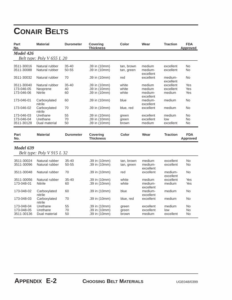
CHOOSING BELT MATERIALS UGE048/0399APPENDIX E-2
Part Material Durometer Covering Color Wear Traction FDANo. Thickness Approved
Model 426Belt type: Poly V 655 L 20
3511-30016 Natural rubber 35-40 .39 in (10mm) tan, brown medium excellent No3511-30088 Natural rubber 50-55 .39 in (10mm) tan, green medium- excellent No
excellent3511-30032 Natural rubber 70 .39 in (10mm) red excellent medium- No
excellent3511-30040 Natural rubber 35-40 .39 in (10mm) white medium excellent Yes173-046-05 Neoprene 40 .39 in (10mm) white medium excellent Yes173-046-06 Nitrile 60 .39 in (10mm) white medium- medium Yes
excellent173-046-01 Carboxylated 60 .39 in (10mm) blue medium- medium No
nitrile excellent173-046-02 Carboxylated 70 .39 in (10mm) blue, red excellent medium No
nitrile173-046-03 Urethane 55 .39 in (10mm) green excellent medium No173-046-04 Urethane 70 .39 in (10mm) green excellent low No3511-30128 Dual material 50 .39 in (10mm) brown medium excellent No
CONAIR BELTS
Part Material Durometer Covering Color Wear Traction FDANo. Thickness Approved
Model 639Belt type: Poly V 915 L 32
3511-30024 Natural rubber 35-40 .39 in (10mm) tan, brown medium excellent No3511-30096 Natural rubber 50-55 .39 in (10mm) tan, green medium- excellent No
excellent3511-30048 Natural rubber 70 .39 in (10mm) red excellent medium- No
excellent3511-30056 Natural rubber 35-40 .39 in (10mm) white medium excellent Yes173-048-01 Nitrile 60 .39 in (10mm) white medium- medium Yes
excellent173-048-02 Carboxylated 60 .39 in (10mm) blue medium- medium No
nitrile excellent173-048-03 Carboxylated 70 .39 in (10mm) blue, red excellent medium No
nitrile173-048-04 Urethane 55 .39 in (10mm) green excellent medium No173-048-05 Urethane 70 .39 in (10mm) green excellent low No3511-30136 Dual material 50 .39 in (10mm) brown medium excellent No

Document number PULLER CONTROL SETTINGS APPENDIX F-1
This table shows the settings for each control parameter set atthe factory. The parameters are set either to the default setting,or to a setting specific to your requirements (Customer col-umn). If you change any value, record it in this column. Keepthese values up-to-date so you can easily restore your puller tonormal operation if the memory is corrupted.
PULLERCONTROLSETTINGS
Code Parameter Range Default CustomerSetpoint Control01 Primary Setpoint 1 0000-999902 Primary Setpoint 2 0000-999903 Secondary Setpoint 1 0000-999904 Secondary Setpoint 2 0000-999905 Jog Setpoint 0000-999906 Output Setpoint 0000-9999Alarms and Limits10 Minimum Limit 0000-999911 Maximum Limit 0000-999912 Low Alarm 0000-999913 High Alarm 0000-999914 Error Alarm 1, ramped 0000-999915 Error Alarm 2, scaled 0000-9999Acceleration and Deceleration16 Acceleration time 000.0-600.017 Deceleration time 000.0-600.0Phase Control18 Lag Pulse Limit 0-999919 Lead Pulse Limit 0-9999Scaling20 Engineering units 000.0-9999
(primary setpoint) 21 Engineering units 000.0-9999
(secondary setpoint)22 Engineering units 000.0-9999
(primary display)23 Engineering units 000.0-9999
(secondary display)Phase Control29 Recovery multiplier 0-100 Scaling30 PPR (external 1-9999
reference input)31 PPR (feedback input) 1-9999 6032 PPR (auxiliary input) 1-999933 Max RPM (external 1-9999
reference input: primary mode)34 Max RPM (feedback: 1-9999 1750
primary mode)35 Max RPM (auxiliary 1-9999
input: primary mode)
If the control's memory is cor-rupted by electrical noise orstatic, you may need to resetthe control parameters.
PULLERCONTROLSETTINGS
Code Parameter Range Default Customer36 Max RPM (external 1-9999
reference input: secondary mode)37 Max RPM (feedback: 1-9999
secondary mode)38 Max RPM (auxiliary 1-9999
input: secondary mode)Scaling Format Selection and Control60 Output format 1-261 Primary scaling mode 0-3 0162 Secondary scaling mode 0-363 Primary display mode 1-2 0164 Secondary display mode 1-2Tuning65 Gain 0-999966 Reset (integral) 0-999967 Rate (derivative) 0-999968 Trim authority 0-10069 Rate threshold 0-100Serial Communications70 Device addresses 1-3271 Baud rate 1-672 Character format 1-373 Control mask 0-255Alarms and Limits74 Zero speed logic 0-1Scaling Format Selection and Control75 Primary mode 0-9999
positive offset76 Primary mode 0-9999
negative offset77 Secondary mode 0-9999
positive offset78 Secondary mode 0-9999
negative offsetSetpoint Control79 Setpoint mask 0-2Analog Input/Output 80 Analog output 0-99
function select81 Analog output range 0-999982 Analog output zero 0-204883 Analog output span 2048-409584 Analog input 0-7
function select85 Analog input zero 0-204886 Analog input span 2048-4095
PULLER CONTROL SETTINGS UGE048/0399F-2 APPENDIX

UGE048/0399 PULLER CONTROL SETTINGS APPENDIX F-3
PID (Proportional, Integral, Differential) tuning is the processof setting the control algorithm parameters (codes 65-69) toachieve optimum performance. While each puller is tunedbefore shipment to optimize performance over the entire speedrange, customers may wish to tune the puller for their specificoperating conditions.
ADVANCEDPROCEDURE:PID TUNING
Code
65
66
67
68
69
Description
Gain - small numberincrease the contributionof the Porportional compo-nent. Zero eliminaltes theGain contribution.
Reset - small numbersincrease the contributionof the Integral component.Zero eliminates the Resetcontribution.
Rate - small numbersincrease the contributionof the Derivative compo-nent. Zero eliminates theRate contribution.
Trim authority - determines how much ofthe output is influenced byGain, Reset and Rate,and how much is deter-mined by feed-forward.
Rate threshold -sets theamount of differential errorrequired before the Rateterm influences the controloutput.
Procedure
1. Set Reset (66) and Rate (67)to zero.
2. Set Trim Authority (68) to100.3. Reduce the Gain setting until
the systembecomes unsta-ble.
4. Increase Gain slightly to re-stabilize the system.
Decrease the value of Resetuntil overshoot is observed.Overshoot occurs when thefeedback goes overthe desiredsetpoint before settling to thedesired value.
1. Decrease the value of Rateuntil the system becomesunstable.
2. Increase Rate slightly to re-stabilize the system.
Start with Trim Authority set at100. If stable operation cannotbe achieved, reduce this para-meter and repeat the tuningprocedure.
If unstable operation occursonly at very low feedback fre-quencies, slightly increase thethis parameter.


UGE048/0399 DIGITAL BELT GAP SENSOR APPENDIX G-1
USING THEDIGITAL BELTGAP SENSOR
The digital belt gap sensor uses a linear scale attached to bothbelts to measure the relative distance between the belts. Therelative distance is shown in thousandths of an inch (.001).The sensor has five buttons:
● On/Off - Turns the device on and off.
● Mode - Press to choose the readout in decimals,fractions, or millimeters.
● + - Press to move up one engineering unit.
● 0 - Press to zero the reading. Because all measure-ments are relative, the sensor can be set to zero at any time by pressing this button.
● - - press to move down one engineering unit.
Readings displays on the digital display.
For more information, refer to the belt gap sensor manual.
On / Off Mode + 0 -

PNEUMATIC UPPER BELT ACTUATOR UGE048/0399G-2 APPENDIX
You can adjust the opening and closing speed of the air cylin-der assembly that operates the upper belt boom assembly byadjusting (lifting and turning) the air regulator handle.
ADJUSTING THEPNEUMATICUPPER BELTACTUATOR
Handle