combined cycle scr systems
TRANSCRIPT

MP313
Combined Cycle SCR Systems
L. J. MuzioFossil Energy Research Corp.
Laguna Hills, CA
2019 Reinhold NOx-Combustion-CCR Round TableFebruary 11, 2019
Salt Lake City, Utah

MP3132
Todays Topics
• Catalyst Sizing
• AIG Tuning; How Done and Importance
• Flue Gas Bypass
• Combined Cycle SCR Operating Temperatures; Issues
• NO2 Effects with SCR; Issues
• Dual Function Catalyst; What is it and how can it be used
Topics

MP3133
Combined Cycle Gas Turbine SCR

MP313
Catalyst Sizing for Combined Cycles
4
Was Enough Catalyst Installed?

MP313
Catalyst Sizing for Combined Cycles
5
Current Catalyst Volume (Catalyst Cost~0.2% of the units capital cost)
0
1
2
3
4
5
6
7
8
9
10
0 2 4 6 8 10
NH
3, p
pm
NOx, ppm
RMS=5% RMS=7.5% RMS=10% RMS=15%

MP313
Catalyst Sizing for Combined Cycles
6
25% More Catalyst (adds ~0.05% of the project capital cost)
0
1
2
3
4
5
6
7
8
9
10
0 2 4 6 8 10
NH
3, p
pm
NOx, ppm
RMS=5% RMS=7.5% RMS=10% RMS=15%

MP313
AIG Tuning
7
• Importance
• Issues
• Impacts of AIG Design

MP313
How Important is the NH3/NOx Distribution
0
2
4
6
8
10
12
14
16
18
20
0 2 4 6 8 10 12 14 16 18 20 22 24 26 28
NOx, ppm, dry at 3% O2
NH3
slip
, dry
at 3
% O
2
Model prediction,pre-tuning, 13% Std.Dev. NH3/NOxModel prediction,post-tuning, 4% Std.Dev. NH3/NOxJune, 2003 Pre-tuning stack test
Post-tuning stacktest
AIG Tuning at South Bay 1: 141MW Boiler (2003)
8

MP313
How Important is the NH3/NOx Distribution
0
2
4
6
8
10
12
14
16
18
20
0 2 4 6 8 10 12 14 16 18 20 22 24 26 28
NOx, ppm, dry at 3% O2
NH3
slip
, dry
at 3
% O
2
Model prediction,pre-tuning, 13% Std.Dev. NH3/NOxModel prediction,post-tuning, 4% Std.Dev. NH3/NOxJune, 2003 Pre-tuning stack test
Post-tuning stacktest
AIG Tuning at South Bay 1: 141MW Boiler (2003)
9

MP313
AIG Tuning: Why is it important?
0
5
10
15
80 85 90 95 100dNOx, %
NH
3-sl
ip, p
pm
3%
6%
9%
11%
14%
RMS
• Performance Improvement (can be as important as the catalyst quantity)
• Becoming More Important as Emission Limits Decrease
• Catalyst Guarantees are Usually based on a given NH3/NOxUniformity (RMS); need to quantify the RMS
10

MP31311
What Happens if (or when!) NH3 Slip Limits Reduced to 2ppm?
0
1
2
3
4
5
6
7
0 2 4 6
NH
3 Sl
ip, p
pmc
NOx, ppmc
RMS=5% RMS=7.5% RMS=10% RMS=15%

MP313
• Tune at reduced NH3 injection rate• Local NH3 slip = 0• Just need to measure NOx at the
exit
• For the NOx-in turn off NH3• For GTs, NOx-in is basically uniform
so can measure one point upstream• Are there issues with this
approach?• Yes
AIG Tuning: How is it Done
𝑵𝑵𝑵𝑵𝟑𝟑𝒊𝒊𝒊𝒊𝒊𝒊= (𝑵𝑵𝑵𝑵𝒙𝒙𝒊𝒊𝒊𝒊𝒊𝒊
− 𝑵𝑵𝑵𝑵𝒙𝒙𝒐𝒐𝒐𝒐𝒐𝒐𝒊𝒊) + 𝑵𝑵𝑵𝑵𝟑𝟑𝒔𝒔𝒔𝒔𝒊𝒊𝒔𝒔𝒊𝒊
Method 1:
12

MP313
Why Tune at Reduce NH3 Injection?• Measure an Accurate RMS• Get a Better Picture of the Distributions
0 10 20
Bottom of Duct, ft.Flow Out of Page
NOx=1.5; NH3 Slip=6ppm
0
10
20
30
40
50
60
East
Wal
l, ft.
0 10 20
Bottom of Duct, ft.Flow Out of Page
NOx=5; NH3 Slip=0 ppm
0
10
20
30
40
50
60
East
Wal
l, ft.
13

MP313
Tuning at Reduced NH3 Injection Rate
• For a Valid RMS Calculation, Local NH3 Slip Needs to be Near Zero• If NH3 Slip is present, it is not accounted for in the RMS
Calculation(i.e just calculating the RMS of the ∆NOx)• Thus, the RMS Value will be Artificially Low
NH3 slip vs NOx Apparent RMS vs NOx
14
0
2
4
6
8
10
12
0 2 4 6 8 10 12 14
NH
3 Sl
ip, p
pm
NOx, ppm
RMS=5% RMS=10% RMS=15% RMS=25%
0
2
4
6
8
10
12
14
16
18
20
22
24
26
0 2 4 6 8 10 12 14
Appa
rent
RM
S,%
NOx, ppm
RMS=5% RMS=10% RMS=15% RMS=25%

MP313
AIG Tuning: How is it Done
𝑵𝑵𝑵𝑵𝟑𝟑𝒊𝒊𝒊𝒊𝒊𝒊= 𝑵𝑵𝑵𝑵𝒙𝒙𝒊𝒊𝒊𝒊𝒊𝒊
− 𝑵𝑵𝑵𝑵𝒙𝒙𝒐𝒐𝒐𝒐𝒐𝒐𝒊𝒊+ 𝑵𝑵𝑵𝑵𝟑𝟑𝒔𝒔𝒔𝒔𝒊𝒊𝒔𝒔𝒊𝒊
Use FTIR• Measure NOx-in, NOx-out, NH3-in, NH3-out
• NH3(i)/NOx(i) = NH3-in(i)/NOx-in(i)Or
• NH3i/NOx(i) = (NOx-in(i)-NOx-out(i) + NH3-out(i))/NOx-in(i)
• Are there issues with this approach?
• YES
Method 2:
15

MP313
FTIR Measurements: Site 1
0
5
10
15
20
25
30
35
40
45
0 1 2 3 4 5 6 7
Amm
onia
Slip
, ppm
vdc
Outlet NOX, ppmvdc
NH3 slip 10% RMS NH3 slip 20% RMS NH3 slip 30% RMS
16

MP313
FTIR Measurements: Site 2
05
1015202530354045
0 10 20 30 40 50
NH3
-in:F
TIR
Calc
NO
x-in
-NO
x-ou
t+N
H3
slip
NH3 in: FTIR Measurement, ppm
B C D E F Y
17

MP313
SCR AIG Tuning
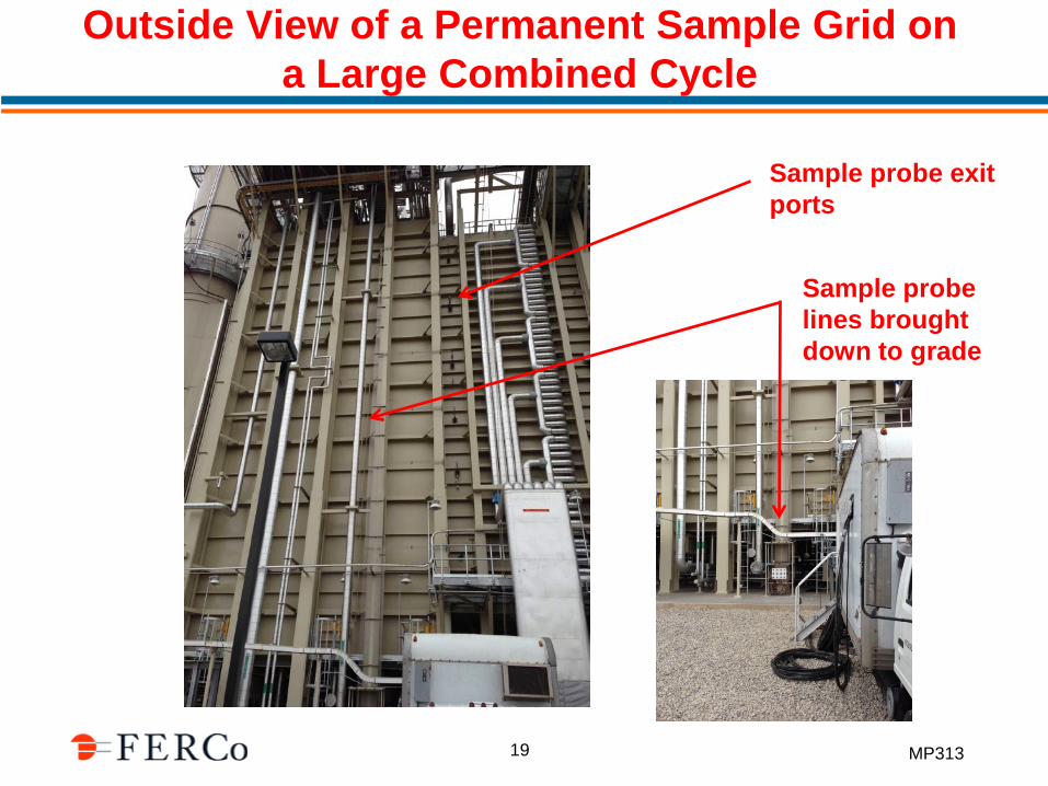
• Tuning is Facilitated by Installing a Permanent Sample Grid at the Catalyst Exit (Particularly for large GT-Combined Cycles)• Not feasible to manually traverse a large combined cycle system
for AIG tuning• Typically need 36 to 60 probes depending on AIG design
• With Permanent Probes, Tuning can Typically be Completed in One Day
• The NOx Profiles at the Exit of the Catalyst can also help Identify Bypass
18
MP313
Outside View of a Permanent Sample Grid on a Large Combined Cycle
Sample probe exit ports
Sample probe lines brought down to grade
19

MP313
Permanent Sample Probes Should Be Installed
20

MP313
FERCo’s Multipoint Instrumentation
• Samples 48 points in 12 to 15minutes (4 groups of 12)
• NOx and O2
21

MP313
Recent AIG Tuning at Redding Electric
• Multi-Point Sampling and Analysis• 40-point sampling grid
22

MP313
AIG Design Affects Tuning
• No Adjustments: Some systems have no adjustment valves-Bad Idea ! ! ! Best RMS ~17%
• 1-D: Commonly used design
Multi Zone: Better
Reagent
Struggle to get RMS ~10%
RMS ~5%
RMS ~3-7%
XNot Much Better Than
23

MP313
Direct Injection/Dual Function Catalyst
24
Direct Injection of Ammonium Hydroxideor Urea
Dual Function or a combination of SCR and Dual Function Catalyst
NOx and CO Removal
MP313
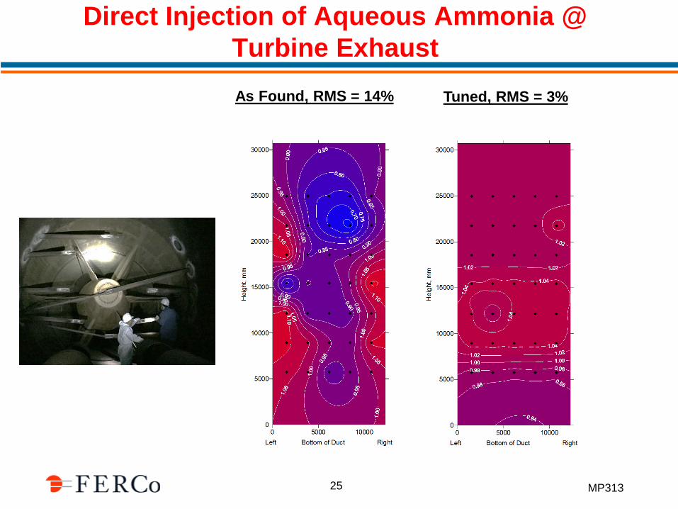
Direct Injection of Aqueous Ammonia @ Turbine ExhaustAs Found, RMS = 14% Tuned, RMS = 3%
25

MP313
NO2 Effects on SCR
26
How is NO2 Formed
a. Gas Turbine Combustion Process
NO + ½ O2 = NO2
Oxidation of Hydrocarbons at low temperatures, produces HO2NO + HO2 = NO2 + OH
b. Oxidation of NO Across the CO Catalyst
X
0%
5%
10%
15%
20%
25%
30%
35%
40%
45%
50%
400 450 500 550 600 650 700
NO
to N
O2
Temperature (°F)

MP313
NO2 Effects on SCR
27
Typical NO2 Characteristics From A Gas Turbine
-50
0
50
100
150
200
250
300
0
0.2
0.4
0.6
0.8
1
1.2
0 200 400 600 800 1000
Load
NO
2/N
Ox
Time
NO2/NOx SCR in Load
MP313
NO2 Effects on SCR*
28
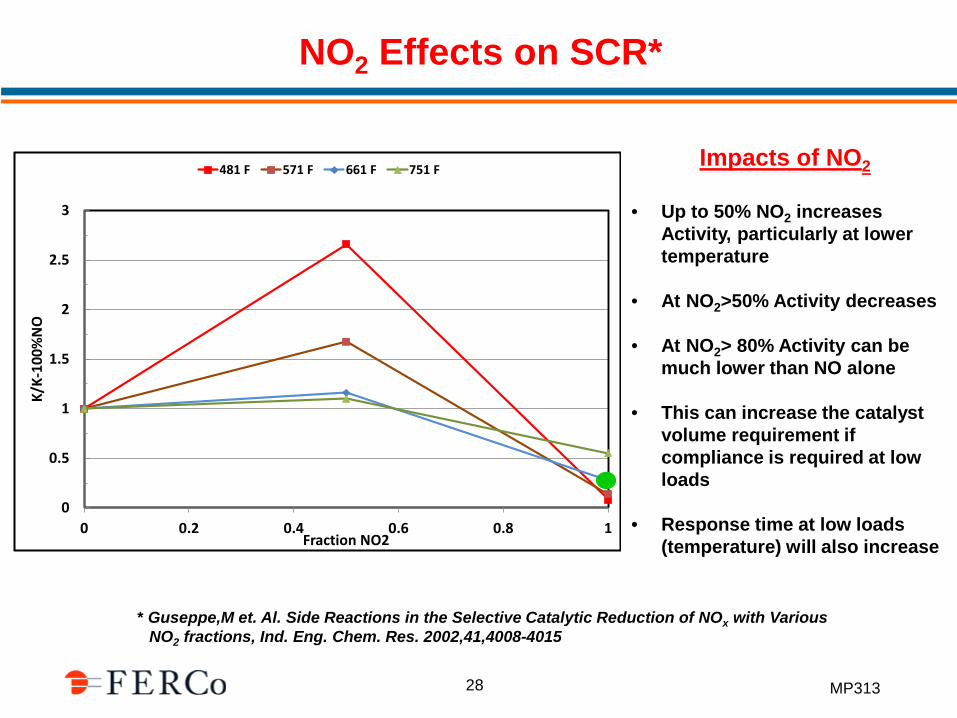
* Guseppe,M et. Al. Side Reactions in the Selective Catalytic Reduction of NOx with Various NO2 fractions, Ind. Eng. Chem. Res. 2002,41,4008-4015
Impacts of NO2
• Up to 50% NO2 increases Activity, particularly at lower temperature
• At NO2>50% Activity decreases
• At NO2> 80% Activity can be much lower than NO alone
• This can increase the catalyst volume requirement if compliance is required at low loads
• Response time at low loads (temperature) will also increase
0
0.5
1
1.5
2
2.5
3
0 0.2 0.4 0.6 0.8 1
K/K-
100%
NO
Fraction NO2
481 F 571 F 661 F 751 F

MP313
Flue Gas Bypass
29
• With Lower NOx and NH3 Limits Bypass Becomes an Important Issue
• Can be Detected with Probes at the SCR Catalyst Exit, Difficult to Quantify
• A Stack Test Series can Help Quantify the Amount of Bypass

MP313
Example A
30
0 5 10 15 200
5
10
15
20
25
30
35
40
45
50
55
60
65
70
75
80
85
0 5 10 15 20
0
5
10
15
20
25
30
35
40
45
50
55
60
65
70
75
80
85
Early 2018 Unit A Unit B
0 5 10 15 200
5
10
15
20
25
30
35
40
45
50
55
60
65
70
75
80
85
Indication of Bypass

MP313
Example A
31
Late 2018 Unit B
0 5 10 15 200
5
10
15
20
25
30
35
40
45
50
55
60
65
70
75
80
85
Early 2018 Unit B
0 5 10 15 200
5
10
15
20
25
30
35
40
45
50
55
60
65
70
75
80
85
0
0.5
1
1.5
2
0 1 2 3 4 5 6
NH3
Slip
, ppm
Month
A B

MP313
Example B
32
0 10 20 30
Feet
0
10
20
30
40
50
Feet
• Probes Can be Located Near the Walls to Detect Bypass as well as Across the Catalyst for Tuning
• Wall, Roof, Floor Probes not used for Tuning

MP313
A Simple Stack Test Can Distinguish:NH3 Maldistribution vs Flue Gas Bypass
NH3/NOx RMS Effects Bypass Effects
0
5
10
15
20
25
30
35
40
0 2 4 6 8 10 12 14
NH
3 Sl
ip, p
pm@
15%
O2
dry
NOx, ppm@15%O2 dry
RMS=10% RMS=20% RMS=30%
0
5
10
15
20
25
30
35
40
0 2 4 6 8 10 12 14
NH
3 Sl
ip, p
pm@
15%
O2
dry
NOx, ppm@15%O2 dry
ByPass=0% ByPass=2.5% ByPass=5% ByPass=7.5%
0
2
4
6
8
10
0 5 10 15 0
2
4
6
8
10
0 5 10 15
33

MP313
TDL Instrumentation
• Testing Facilitated Using a Continuous TDL NH3Analyzer
• Data Set Can be Generated in Less than a Day
• Data Available in Real Time
• Unisearch NH3 TDL• Dual Path• Two Channel• Fiber Optic Coupled
34

MP313
TDL NH3 Measurements on a Large Combined Cycle
NH3/NOx RMS Effects Bypass Effects
35
0
5
10
15
20
25
30
35
40
0 5 10 15
NH
3 Sl
ip, p
pm@
15%
O2
dry
NOx, ppm@15%O2 dry
RMS=10% RMS=20% RMS=30% Test Data
05
10152025303540
0 5 10 15
NH
3 Sl
ip, p
pm@
15%
O2
dry
NOx, ppm@15%O2 dry
Test Data ByPass=0% ByPass=2.5%
ByPass=5% ByPass=7.5% RMS=10%

MP313
SCR Operating Temperatures
36
• Seeing More and More Combined Cycle SCR/CO Catalyst Systems Operating in a Temperature Range of 570-630°F
Affects catalyst response time (control issues)

MP313
SCR Catalyst Response Times
37
0
100
200
300
400
500
600
700
800
0
5
10
15
20
25
30
35
40
0 10 20 30 40 50 60
Tem
pera
ture
, F
NO
x, N
H3
Slip
Time, min
NOx (ppmvd) NH3 Slip (ppmv) Temp (F)
NH3 Injection Start @ 580F
NH3 Slip Increase due to Temp increase
NH3 Injection Start @ 700F
NH3 Off

MP313
What is Dual Function Catalyst?
• New Catalyst Introduced by Catalyst Suppliers• Reduces both NOx and CO in one catalyst bed• Basically SCR catalyst that incorporates precious metals• Suppliers:
• Umicore• Cormetech• Johnson-Matthey(?)
• Typical Performance
T NOx CO NH3/NOx dNOx dCOF ppm ppm % %
700 70 0 1 96 -700 70 500 1 93 99.4
Inlet Performance
38

MP313
Recent Retrofit: REU (2- 45 MW GT Combined Cycles: 2 ppm NOx/5 ppm NH3 Slip)
Remove EMX Media, Replace w/Dual Function
Install 40 pt Probe Grid
Direct Urea Sol. Injection (6 atomizers)
0 5 10 15 20 Bottom Of Duct, ft.Standing at Stack, Looking Towards Turbine
0
5
10
15
20
25
30
Nor
th W
all,
ft.
NH3/NOx Dist (RMS = 7.2% (44MW))
Retrofit by: REU/Combustion Components Assoc/Umicore
39
MP313
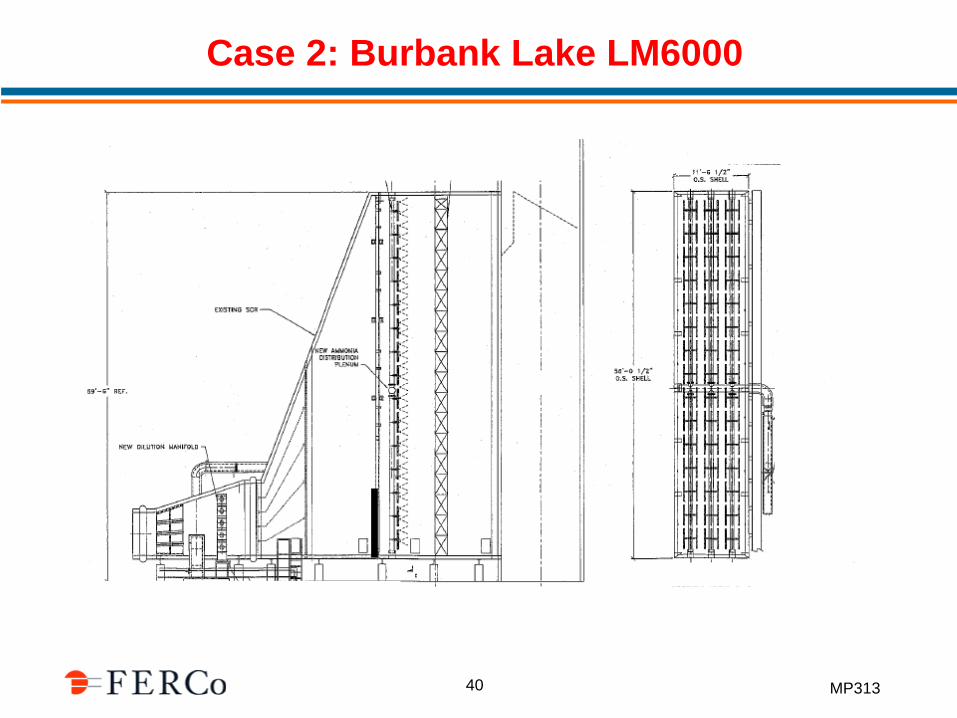
Case 2: Burbank Lake LM6000
Solid wall 6 ft high
40

MP313
Case 2: Burbank Lake LM6000
• Minor Improvements will Not Allow 2.5 ppm NOx/5 ppm NH3Slip
0
1
2
3
4
5
6
7
2011 2012 2013 2014 2017 2018
NO
x, N
H3 S
lip, P
PM@
15%
O2
NH3
NOx
Post AIG and Bypass Improvement
41

MP313
Case 2: Burbank Lake LM6000 (Recommended Modifications)
Move AIG to Here
Remove CO Cat & AIG
Replace SCR Catalyst with SCR/Dual Function Catalyst
42

MP313
Irvine Landfill (7-3MW Caterpillar Reciprocating Engines)
43

MP31344
Irvine Landfill (7-3MW Caterpillar Reciprocating Engines)

MP313
Trimethysilanol: (CH3)3Si--O—Si(CH3)3
Siloxanes
45
To Engine/SCR

MP31346
Siloxane Impacts

MP31347
Irvine Landfill (Engine Emission Control Systems)

MP31348
CO Catalyst Oxidation of NH3

MP31349
CO Catalyst Oxidation of NH3

MP313
Summary
• Make Sure Sufficient Catalyst Has Been Installed
• Make Sure the AIG Design is Consistent with the NOx and NH3 Slip Limits that Need to be Achieved
• Install a Permanent Probe Grid at the SCR Exit (facilitates tuning and assessing bypass)
• Assess NO2 Issues at Low Loads; Dual Function Catalyst can Eliminate NO2 Formation Across Traditional CO Catalyst
50
