combined junction temperature and bond wire lift-off monitoring using auxiliary-emitter resistor
TRANSCRIPT
1
CORPE
Combined Junction Temperature and Bond-wire Lift-
off Monitoring Using Auxiliary-Emitter Resistor
Nick Baker
9th November 2016
CORPE

2
CORPE
PhD Summary 2013-2016
Junction Temperature Measurement of IGBTs
- Junction Temperature is important for reliability
- Difficult to measure during converter operation
- PhD studied using the electrical behaviour of the semiconductor
as the ‘temperature sensor’
- No need for additional sensors inside the power module
Semiconductor Die An IGBT Module
Measure the temperature
of 1x1cm2 silicon
Powerex 2012
Integrated sensors take up
active area
In collaboration with

3
CORPE
Causes of Failure in Power Semiconductors
Temperature Swings and Coefficients of Thermal Expansion
- An IGBT module is constructed of many different materials
- Repetitive stress-strain from mismatches in CTE causes wearout
0
5
10
15
20
25
30
Copper Solder Silicon Aluminium DBC
CT
E (
pp
m/°
C)
Coefficients of Thermal Expansion (CTE)
Inside an IGBT module
In collaboration with
In collaboration with
4
CORPE
PhD Summary 2013-2016
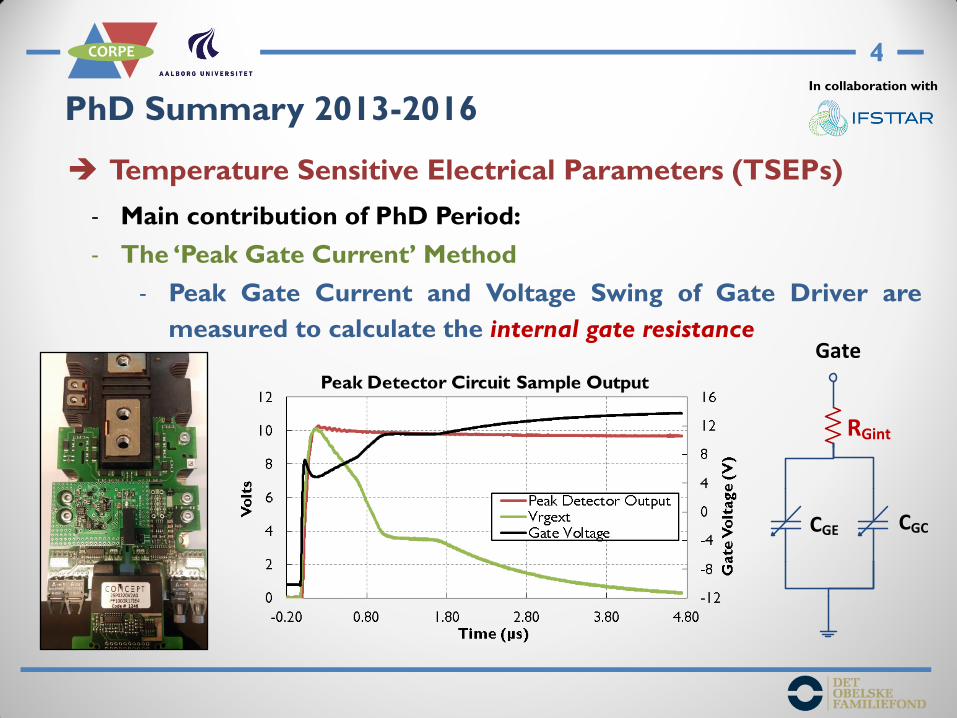
Temperature Sensitive Electrical Parameters (TSEPs)
- Main contribution of PhD Period:
- The ‘Peak Gate Current’ Method
- Peak Gate Current and Voltage Swing of Gate Driver are
measured to calculate the internal gate resistance Gate
CGCCGE
RGint
In collaboration with
5
CORPE
PhD Summary 2013-2016
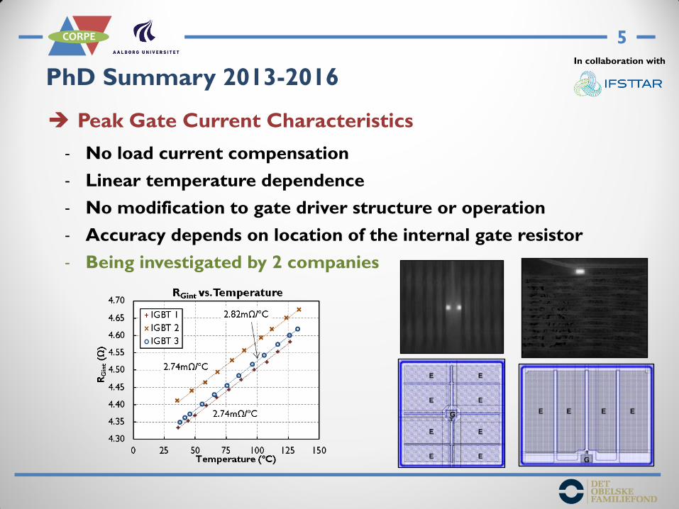
Peak Gate Current Characteristics
- No load current compensation
- Linear temperature dependence
- No modification to gate driver structure or operation
- Accuracy depends on location of the internal gate resistor
- Being investigated by 2 companies
In collaboration with
6
CORPE
IGBT
C
E
G
Bo
nd
-wire
+
-
Gat
e D
rive
r
RGint
ICIG
IGBT
C
E
G
Bo
nd
-wire
Aux. E
+-
Gat
e D
rive
r
RGint
ICIG
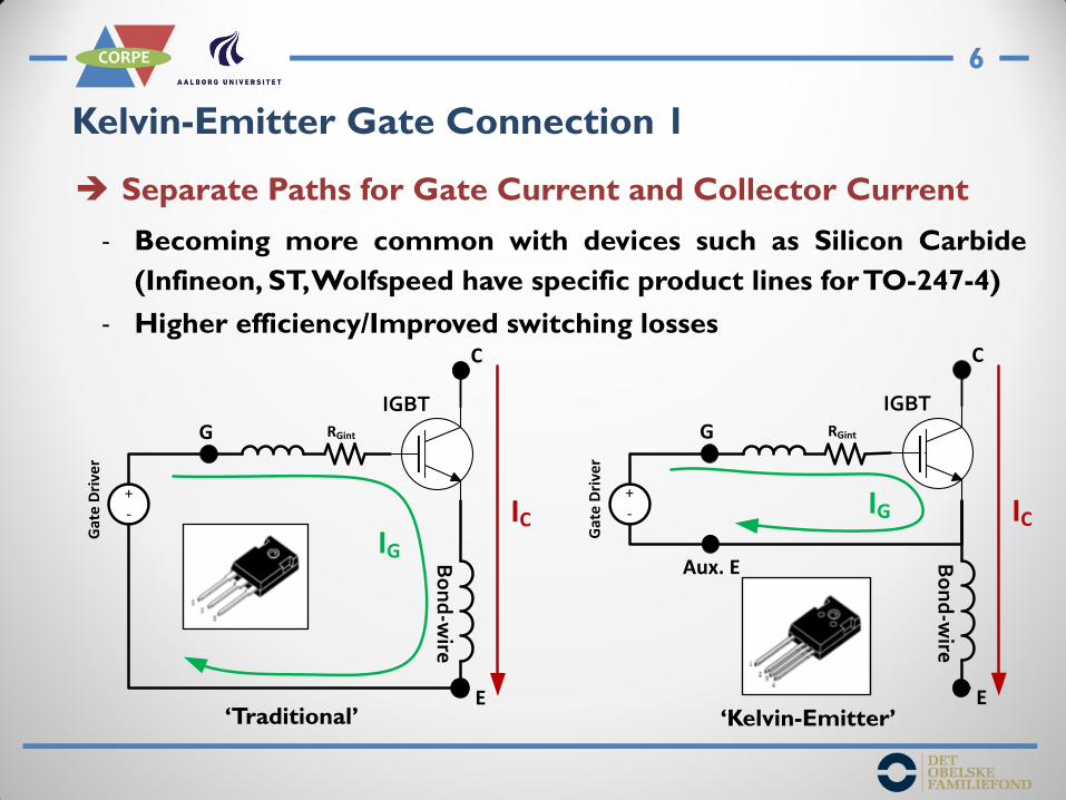
Kelvin-Emitter Gate Connection 1
Separate Paths for Gate Current and Collector Current
- Becoming more common with devices such as Silicon Carbide
(Infineon, ST, Wolfspeed have specific product lines for TO-247-4)
- Higher efficiency/Improved switching losses
‘Traditional’ ‘Kelvin-Emitter’
7
CORPE
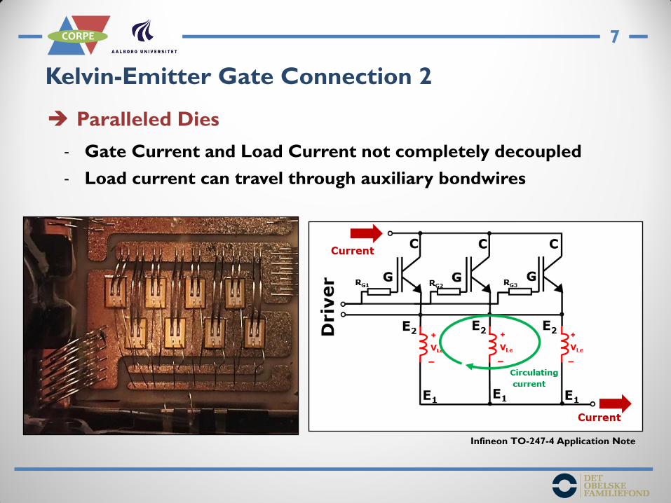
Kelvin-Emitter Gate Connection 2
Paralleled Dies
- Gate Current and Load Current not completely decoupled
- Load current can travel through auxiliary bondwires
Infineon TO-247-4 Application Note
8
CORPE
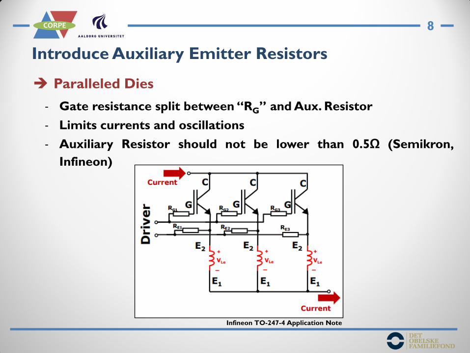
Introduce Auxiliary Emitter Resistors
Paralleled Dies
- Gate resistance split between “RG” and Aux. Resistor
- Limits currents and oscillations
- Auxiliary Resistor should not be lower than 0.5Ω (Semikron,
Infineon)
Infineon TO-247-4 Application Note

9
CORPE
Introduce Auxiliary Emitter Resistors
Paralleled Dies
- Gate resistance split between “RG” and Aux. Resistor
- Limits currents and oscillations
- Auxiliary Resistor should not be lower than 0.5Ω (Semikron,
Infineon)
Infineon TO-247-4 Application Note

10
CORPE
Auxiliary Emitter Resistor Module Simulation
6x Paralleled SiC MOSFETs 50A (300A double pulse test)
- Step Resistances 1mΩ, 1Ω and 6Ω for each Aux. Source path
- Peak Currents through Aux. Source of MOSFET 1:
- 1mΩ: 30A
- 1Ω: <10A
- 6Ω: <5A
- Aux. Emitter/Source connection becoming more common
- Aux. Resistors may be used in modules with paralleled dies

11
CORPE
Bond-wire Lift-Off Detection 1
Most commonly studied failure mechanism
- Large amount of research on indicators to predict failure
- Usually device electrical behaviour is monitored
- Stop power module operation before catastrophic failure occurs

12
CORPE
Bond-wire Lift-Off Detection 2
Forward Voltage Drop used for Detection
- Established in lab, but how to prevent false positives in field?
- Small increase in Voltage before device failure (5%)
- Forward Voltage is influenced by:
- Packaging degradation, Gate Driver, VTH, Temperature..
40mV VCE
IGBT C
E
G
VV
Bond-wire
13
CORPE
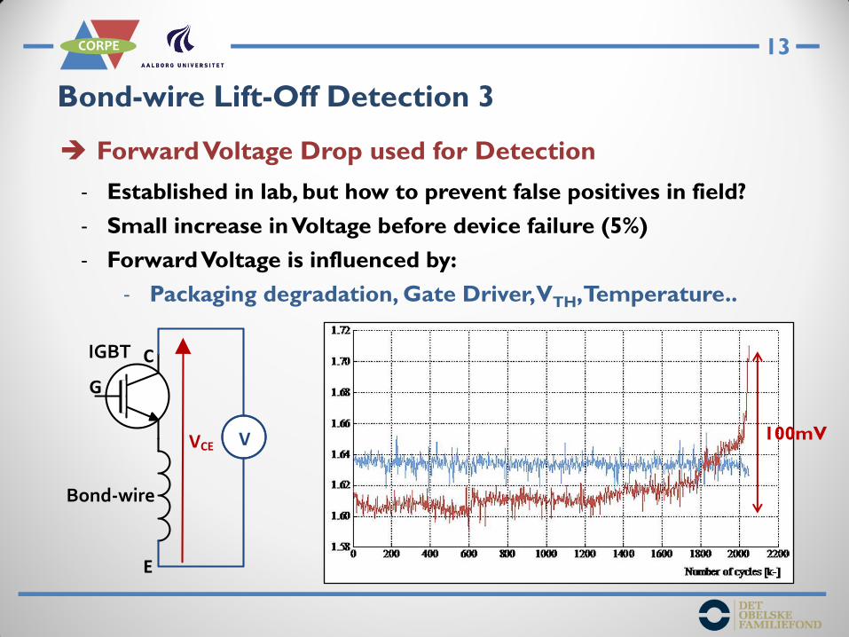
Bond-wire Lift-Off Detection 3
Forward Voltage Drop used for Detection
- Established in lab, but how to prevent false positives in field?
- Small increase in Voltage before device failure (5%)
- Forward Voltage is influenced by:
- Packaging degradation, Gate Driver, VTH, Temperature..
100mV VCE
IGBT C
E
G
VV
Bond-wire

14
CORPE
Bond-wire Lift-Off Detection 4
Forward Voltage Drop used for Detection
- Established in lab, but how to prevent false positives in field?
- Small increase in Voltage before device failure (5%)
- Forward Voltage is influenced by:
- Packaging degradation, Gate Driver, VTH, Temperature..
60mV VCE
IGBT C
E
G
VV
Bond-wire

15
CORPE
Bondwire Lift-Off Detection with Aux. Emitter
Provides a specific measurement
- Only dependent on bondwire degradation (and temperature)
- Potential for increased sensitivity in both % and absolute terms if
an auxiliary resistor is included
VCE
IGBT C
E
G
VV
Bond-wire
IGBT C
E
G
VV
Bo
nd
-wire
Aux. E
VEE
Aux. Resistor
16
CORPE
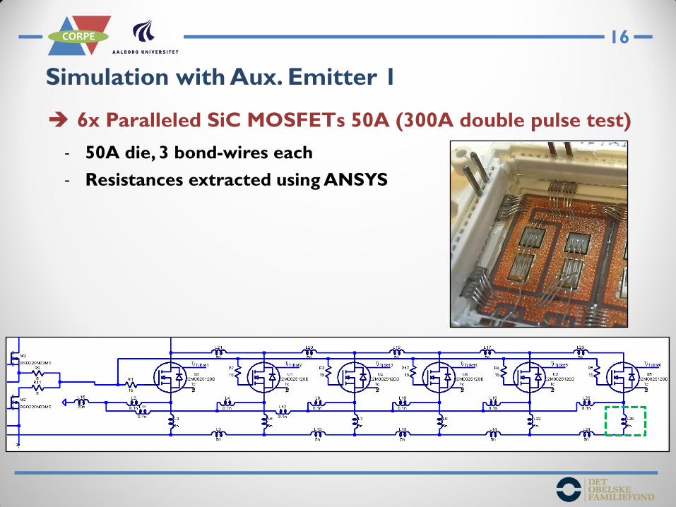
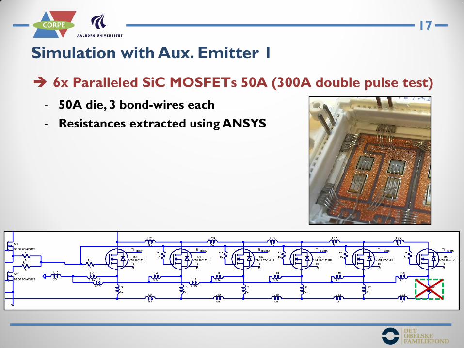
Simulation with Aux. Emitter 1
6x Paralleled SiC MOSFETs 50A (300A double pulse test)
- 50A die, 3 bond-wires each
- Resistances extracted using ANSYS
17
CORPE
Simulation with Aux. Emitter 1
6x Paralleled SiC MOSFETs 50A (300A double pulse test)
- 50A die, 3 bond-wires each
- Resistances extracted using ANSYS
18
CORPE
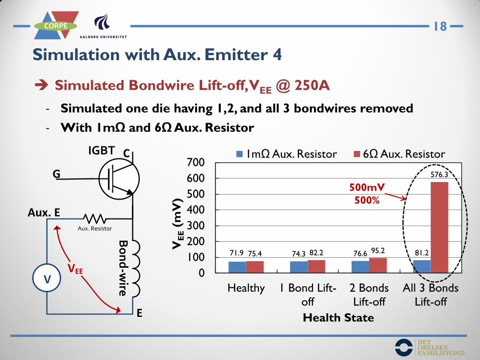
Simulation with Aux. Emitter 4
Simulated Bondwire Lift-off, VEE @ 250A
- Simulated one die having 1,2, and all 3 bondwires removed
- With 1mΩ and 6Ω Aux. Resistor
71.9 74.3 76.6 81.2 75.4 82.2 95.2
576.3
0
100
200
300
400
500
600
700
Healthy 1 Bond Lift-
off
2 Bonds
Lift-off
All 3 Bonds
Lift-off
VE
E (
mV
)
Health State
1mΩ Aux. Resistor 6Ω Aux. Resistor IGBT C
E
G
VV
Bo
nd
-wire
Aux. E
VEE
Aux. Resistor
500mV
500%

19
CORPE
Circuit for Monitoring during Operation
More simple measurement circuit
- VCE requires high component count and protection against high
voltage in the off-state
- VEE is a low voltage signal (perhaps some spikes during switching)
- Possible to measure with just an instrumentation amplifier
IGBT C
E
G
Bo
nd
-wire
Aux. E
VEE
Aux. Resistor
Instrumentation Amplifier
VCE Measurement Concept (Bęczkowski 2013)

20
CORPE
Circuit for Monitoring during Operation
More simple measurement circuit
- VCE requires high component count and protection against high
voltage in the off-state
- VEE is a low voltage signal (perhaps some spikes during switching)
- Possible to measure with just an instrumentation amplifier

21
CORPE
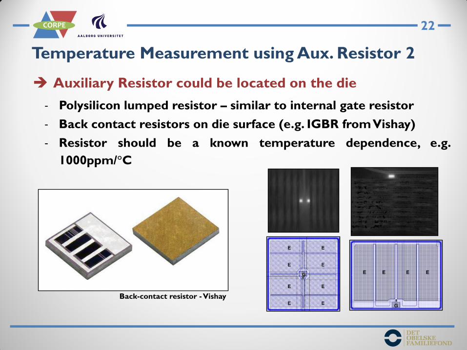
Temperature Measurement using Aux. Resistor 1
Auxiliary Resistor could be located on the die
- Resistor now also acts as a temperature sensor
Gate
Aux. Emitter
Emitter
100mA-
500mACurrent
Source V
Aux. Resistor
22
CORPE
Temperature Measurement using Aux. Resistor 2
Auxiliary Resistor could be located on the die
- Polysilicon lumped resistor – similar to internal gate resistor
- Back contact resistors on die surface (e.g. IGBR from Vishay)
- Resistor should be a known temperature dependence, e.g.
1000ppm/°C
Back-contact resistor - Vishay
23
CORPE
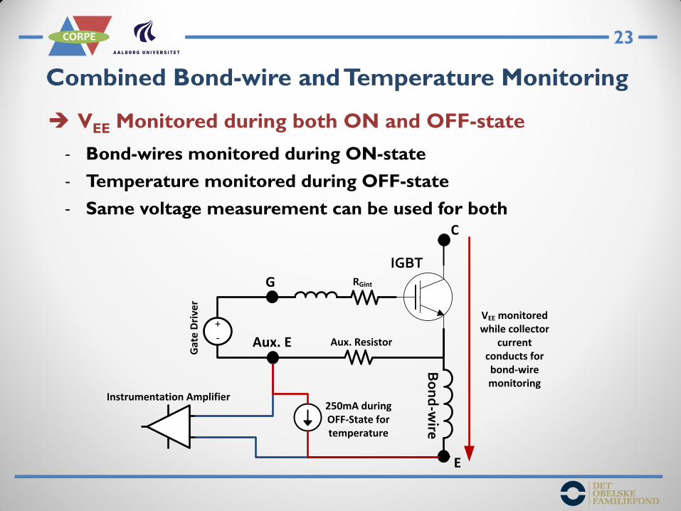
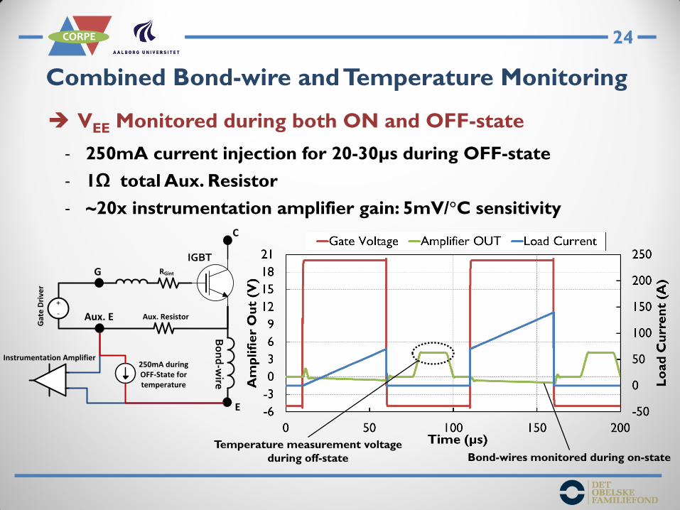
Combined Bond-wire and Temperature Monitoring
VEE Monitored during both ON and OFF-state
- Bond-wires monitored during ON-state
- Temperature monitored during OFF-state
- Same voltage measurement can be used for both
250mA during OFF-State for temperature
IGBT
C
E
G
Bo
nd
-wire
Aux. E
+-
Gat
e D
rive
r
RGint
Instrumentation Amplifier
Aux. Resistor
VEE monitored while collector
current conducts for bond-wire monitoring
24
CORPE
Combined Bond-wire and Temperature Monitoring
VEE Monitored during both ON and OFF-state
- 250mA current injection for 20-30µs during OFF-state
- 1Ω total Aux. Resistor
- ~20x instrumentation amplifier gain: 5mV/°C sensitivity
250mA during OFF-State for temperature
IGBT
C
E
G
Bo
nd
-wire
Aux. E
+
-
Gat
e D
rive
r
RGint
Instrumentation Amplifier
Aux. Resistor
Temperature measurement voltage
during off-state Bond-wires monitored during on-state

25
CORPE
Summary
A Power Module with Auxiliary Emitter/Source Resistor
- Improves current sharing
- Provides opportunity to specifically monitor bond-wire lift-off,
with higher sensititvity
- Provides opportunity to implement junction temperature
monitoring
- Patent application for Tj measurement using the auxiliary emitter
resistor

26
CORPE
www.corpe.et.aau.dk
CORPE