combined reverse engineering and cad approach for mould modelling in casting simulation
TRANSCRIPT
Combined reverse engineering and CADapproach for mould modelling in castingsimulation
A. Salmi*1, E. Atzeni1, F. Calignano2, P. Minetola1 and L. Iuliano1
Casting process simulation is nowadays established as a strategic tool in process optimisation to
improve product quality. However, sometimes the required three-dimensional mathematical
model of the casting is not available, because the original drawings are not-up-to date and parts
are subjected to design changes. In these cases, reverse engineering (RE) is the most suitable
method to reconstruct the geometrical model of the casting. In this paper, a RE-based procedure
is proposed to obtain the three-dimensional CAD model of a casting from its physical equipment.
The proposed procedure involves four phases: pre-digitising, digitising of equipment parts,
surface reconstruction, and three-dimensional CAD modelling. An aeronautical part fabricated by
sand casting is selected as case study to verify the feasibility of this approach. Outcomes prove
that the RE methodology is adequate to virtually reconstruct the geometry of each single part of
the equipment as well as the whole geometry of the assembled mould.
Keywords: Reverse engineering, Sand casting, 3D CAD modelling, FEM, Mesh
IntroductionIn last decades, casting process simulation throughcomputer aided engineering (CAE) codes was initiallyadopted by few foundries for the analysis of solidification,in order to optimize risers location.1 Then the use ofsimulation has been extended to predict defects, deforma-tion, residual stresses, and microstructure of cast parts.2–6
On the market, several simulation software packages areavailable for foundry applications. CAE packages arebased on finite elements (FE) or finite volume/differencemethods. In both cases, the three dimensional CADmodel of the casting is required, because FE mesh isgenerated on it. In foundry the availability of themathematical model is often a critical issue. This is thecase of old castings, where the original bi-dimensionaldrawings define only partially the part geometry, i.e.coupling surfaces. In other cases, a pre-existing product isredesigned due to a revision of the process since mouldgeometry should be modified or the gating systemredesigned, but CAD models are not updated accord-ingly. In these circumstances three dimensional CADmodels can be reconstructed starting from availableequipment (cores, core boxes, patterns, moulds, etc.)using reverse engineering (RE) techniques.7,8
RE is a widespread technology that enables us togenerate a virtual model of a physical part.9,10 There are
several application areas of RE, including metrology,quality control, design, virtual reality, medical and surgicalapplications, and preservation of Cultural Heritage. REprocess begins with the digitisation of an object, which isthe acquisition of points (point cloud) belonging to thepart surfaces. Subsequently the point cloud can beconverted into .STL file format or imported directly intothe software used for surfaces reconstruction. Then a set ofsurfaces, fitting the point clouds automatically or semi-automatically, creates the CAD model of the part.11–13
Up to now, RE techniques have been applied infoundry within a limited range of applications. Forexample, RE is used for inspection purposes to retrievethe actual geometries of tools or castings. In fact, throughperiodical scans, tool wear can be monitored and worntools can be replaced by copies of the original ones.Furthermore, as-cast parts are digitised to inspect theiractual geometry and check if quality requirements are metin terms of dimensional and geometrical tolerances.14
Another specific application, reported in literature, is thegeneration by digitising process of three-dimensionalCAD surfaces for rapid tooling.7 As regards numericalsimulation, the application of RE techniques to create thegeometrical model of the casting was studied by severalauthors,7,8,15,16 but the approach is typically the genera-tion of the finite element (FE) model directly from scandata, bypassing the surface generation step. In such a waythe geometry is quickly obtained, but it cannot be easilyedited. In addition to this, the availability of an editablethree-dimensional CAD model is a mandatory require-ment of the redesign process. In fact, because simulationis intended to help engineers during the design phase, thethree-dimensional CAD model should be easily modified
1Politecnico di Torino, Department of Management and ProductionEngineering (DIGEP), Corso Duca degli Abruzzi, 24 - 10129 Torino, Italy2Istituto Italiano di Tecnologia, Center for Space Human RoboticsIIT@Polito, Corso Trento, 21 - 10129 Torino, Italy
*Corresponding author, email [email protected]
� 2014 W. S. Maney & Son Ltd.Received 15 February 2013; accepted 17 December 2013DOI 10.1179/1743133613Y.0000000101 International Journal of Cast Metals Research 2014 VOL 27 NO 4 213

according to simulation outputs. Moreover, it is impor-tant to point out that the virtual model for CAE analysismust reproduce the geometry of the mould and not thegeometry of the cast part, since the cast part is affected byshrinkage and deformation occurring during solidifica-tion, cooling, demoulding, and gating system removal.This last topic has not been studied in depth yet inscientific papers, but it is of paramount importance in aconcurrent engineering scenario.
Focusing on these issues, a novel procedure to obtainthe mathematical CAD model and the FE tetrahedralmesh of a casting from physical equipment is proposedin this paper with special focus on sand casting process.The procedure involves the use of a three-dimensionalscanner to digitise mould parts. Point clouds are alignedinto a global reference frame and then processed toobtain an editable three-dimensional model of theassembled mould. If needed, the reconstructed modelis integrated by importing standard geometries in a 3DCAD environment. Each phase of the procedure isdetailed in this study and critical aspects are discussed.This procedure is then applied to an aerospacecomponent, selected as case study, to let benefits andlimitations come out.
Reverse engineering procedureThe proposed RE procedure to obtain the CAD modelfrom the actual casting is detailed in the following foursections: pre-digitising, digitizing of single parts,
surfaces reconstruction, and three-dimensional CADmodelling.
Pre-digitisingA sand casting mould is an assembly of different parts.Some parts are standard components, such as filters andsleeves, and their three-dimensional CAD models aregenerally supplied by manufacturers. On the contrary,other parts are developed for the specific cast product. Ifthe three-dimensional CAD models of these expresslydesigned parts are not available, RE is the best practiceto be adopted for digitising them. However, the mostchallenging issue of this approach is the correctalignment of each digitised part according to its actuallocation in the assembled mould. This problem arisesbecause the scan data of each part has its own referenceframe when the part is digitised separately.
Therefore, the pre-digitising procedure illustrated inFig. 1 is proposed to overcome this problem. Theprocedure consists of some scans of each part of themould when the part is in its location in the assembly.Information gathered from pre-digitisation is then usedto refer the point clouds of all the parts of the equipmentaccording to a unique reference frame that will beaddressed as global reference frame in the following. Atthe initial stage of the procedure, the mould is fullyassembled and consists of N parts. The counter i is setequal to N. Then the human operator evaluates if i isequal to 1. If this condition is not true, a pre-digitisationof visible parts of the assembled mould is performed.During pre-digitisation, the number of scans and thepoints density is much lower than the one of a completedigitisation because scan data is only used for partsalignment but not for surfaces reconstruction.Afterwards the operator identifies the j parts (1,j#i)with sufficient scan data for alignment and removes allthese parts from the assembly except one: such part,arbitrarily chosen by the operator, will be the referenceelement in the next pre-digitisation loop. The counter i isthen updated according to the equation i5i – (j – 1) thatis the number of remaining parts to be pre-digitised. Thepre-digitising phase continues through similar loopsuntil i is equal to 1. When this condition is true thisphase is over because all the parts of the assembledmould are referenced in the global reference frame.
Digitising of single partsIn the digitisation phase, each part of the equipmentwhose CAD model is unavailable is digitised singly. Theprocedure followed in this phase is detailed in Fig. 2.
The surfaces of an equipment part can consist ofconvex or concave shapes. It is well known that convexshapes can be easily digitised, while concave ones couldcomplicate the scanning process or even prevent it. Inthe case of concave geometries, especially small deepholes, the missing information on the scan data can beretrieved by the digitization of reverse shapes. Forinstance, positive parts, such as sand cores, cope anddrag moulds, are digitised to complete the geometries ofcore boxes and pattern plates. Thus, the complete digitalmodel of each part can be generated by aligning thepartial scans from equipment and from correspondingsand part with respect to the same reference framebefore merging the scans together. If the geometry of thepart cannot be completed by the digitisation of thereverse shapes, a partial point cloud is obtained.
1 Pre-digitising procedure
Salmi et al. Combined reverse engineering and CAD approach for casting simulation
214 International Journal of Cast Metals Research 2014 VOL 27 NO 4

Therefore, the digitisation output for each part is acomplete or partial point cloud. In this phase M is thenumber of parts of the equipment that should be singlydigitised and L identifies the number of parts whose 3DCAD model is available. M is equal to N–L or greater ifchillers are partially included in the pre-digitised sandparts of the assembled mould. If a partial point cloud isobtained for K parts, the geometry of the remaining (M– K) parts is completely defined by digitisation data.
Surface reconstructionTo construct editable CAD surfaces, the (M–K)complete point clouds and K partial point clouds shouldbe first aligned in the global reference frame by means ofthe pre-digitisation data (Fig. 3). Once aligned, singlepoint clouds can be pre-processed for denoising,smoothing and density reduction. These softwareoperations are needed since they reduce the complexityof the point cloud and ease the surfaces reconstructionprocess.17 However, particular attention should be paidin applying such operations, because they could alter thescan data exceeding the tolerances required by the sandcasting process. The point clouds are then convertedinto polygonal models by generating an unstructuredtriangular mesh.
Considering the polygonal models of the parts in theirassembled state, small gaps could be detected amongadjacent parts. Some gaps are due to the clearanceprovided in the design stage to ease the assemblyoperation and to avoid mould distortion due to thermalstresses during filling and solidification. This kind of gapcan be identified because the distance between adjacentparts is bigger than 0?5 mm. Other smaller gaps, ranging
from 0?05 to 0?5 mm, are the result of the deviation withrespect to nominal dimension that is induced by theequipment production. In fact the scanning activity isproven to accurately copy actual geometries.10,18
However, all these gaps must be removed in the three-dimensional model for numerical simulation, becausethey increase the complexity of the model withoutsignificantly affecting simulation outcomes. Moreover,in foundry practice visible cavity gaps are removedduring the manual assembling operation by using afiller. Thus, in the virtual environment, the triangulatedmodels of two or more adjacent parts are combined tocreate a single entity. The small gap (Fig. 4a) is reducedby building one or more narrow bridges. In such a way,the gap is divided into separately fillable holes (Fig. 4b),that can be easily closed using a RE software tool(Fig. 4c).
The gap removal operation causes the loss of theinterface information. However, the identification of theinterface is important to allow the splitting of the mouldgeometry again into single parts in the next CADmodelling phase. Prior to removing a gap, it is necessaryto identify and extract the cutting feature (dashed line inFig. 4) for splitting the mould model in next phase.Cutting feature recognition is performed by computingthe best fit geometric entity from the gap interface.
Another requirement is the absence of overlappingsurfaces. However there are M–(N–L) elements that arepartially included in the sand parts and thus overlappingpolygonal faces are detected on them. For instance, inthe forming stage a chiller is placed on the surface of thepattern plate; the digitisation, alignment and assemblyphases will reproduce this mating. Thus, the polygonal
2 Digitising procedure for each part of equipment
Salmi et al. Combined reverse engineering and CAD approach for casting simulation
International Journal of Cast Metals Research 2014 VOL 27 NO 4 215

faces of the chiller are overlapping the ones of thepattern plate. To solve this ambiguity, the more regularfaces are kept and the others are discarded. If a gapresults from this operation, it is closed by the gapremoval procedure previously described.
So far, the cavity of the mould is completely describedby an unstructured triangular mesh and surfaces can bedefined on it. In the step of surface generation, primitiveand/or free form surfaces are defined on the polygonalmesh by using a RE tool. Generally cast parts can bedescribed either by classical shapes connected by highlycurved features, e.g. the gating system geometry, or byfree-form surfaces that usually define the mould cavity.Algorithms developed in recent years for the reconstruc-tion of the CAD model from a polygon mesh involve asegmentation process.10,19–21 Segmentation is the pro-cess of partitioning the polygonal mesh into severalplanar, concave or convex regions, according tocurvature changes, thus simplifying the surface genera-tion. Different strategies that are based on regiondetection or curvature detection can be used forsegmentation. Subsequently, autosurfacing or featurerecognition operations are applied to reconstruct theparts surfaces. Autosurfacing is adopted in the case of
free-form surfaces, while feature recognition is com-monly used for classical shapes. Following this strategythe complex actual geometry of the mould cavity isgenerated by autosurfacing, whereas features recogni-tion is applied to ancillary parts, i.e. runners, risers, etc.
Three-dimensional CAD modellingThe cutting features and the reconstructed surfaces arethen imported into a three-dimensional CAD environ-ment and a validity check is performed in order to detectany corruption, e.g. geometry faults, trim loop faults,unfixed blend faults, self-intersection faults, genericgeometry–topology faults, etc. As a matter of fact, thepresence of a corrupted body may result in unexpectedoutcomes when a modelling operation is performed onit.
After the validation, the RE reconstructed geometry isintegrated by available 3D CAD models to complete themould assembly with standard components such asfilters and insulation sleeves. In order to mate these 3DCAD models to the RE geometry, an edge-to-edge orface-to-face alignment, or a combination of both themethods is performed. It is important to point out thatthe alignment is possible since mating surfaces of the REreconstructed model are classical geometries. This is aconsequence of the segmentation strategy adoptedduring the surface generation phase.
After the alignment operation, special attentionshould be paid again to the overlapping surfaces andintersections. Mainly intersections are the consequenceof deviations between analogous CAD entities of the 3DCAD model and the RE reconstructed geometry.Especially, the greater the digitisation error, the greaterthe average deviation between the two geometries.Overlapping surfaces must be merged just into one
3 Surface reconstruction and three-dimensional CAD modelling procedure
4 Gap removal and cutting feature identification
Salmi et al. Combined reverse engineering and CAD approach for casting simulation
216 International Journal of Cast Metals Research 2014 VOL 27 NO 4
and, if needed, new edges are defined. Intersections aresolved by maintaining one geometry and extending ortrimming the other one.
The resulting geometry is an editable model of theassembled mould including the gating system, filters,risers, chillers, and insulation sleeves. At this point coreprints are modelled by means of the correspondingcutting features data that were previously extractedduring the removal of gaps. From the point of view ofnumerical simulation, the CAD model of the assembledmould is so achieved and it can be exported to a FEMenvironment. On the contrary for cast redesign purposesthe mould model should be split again into single partsusing the extracted cutting features.
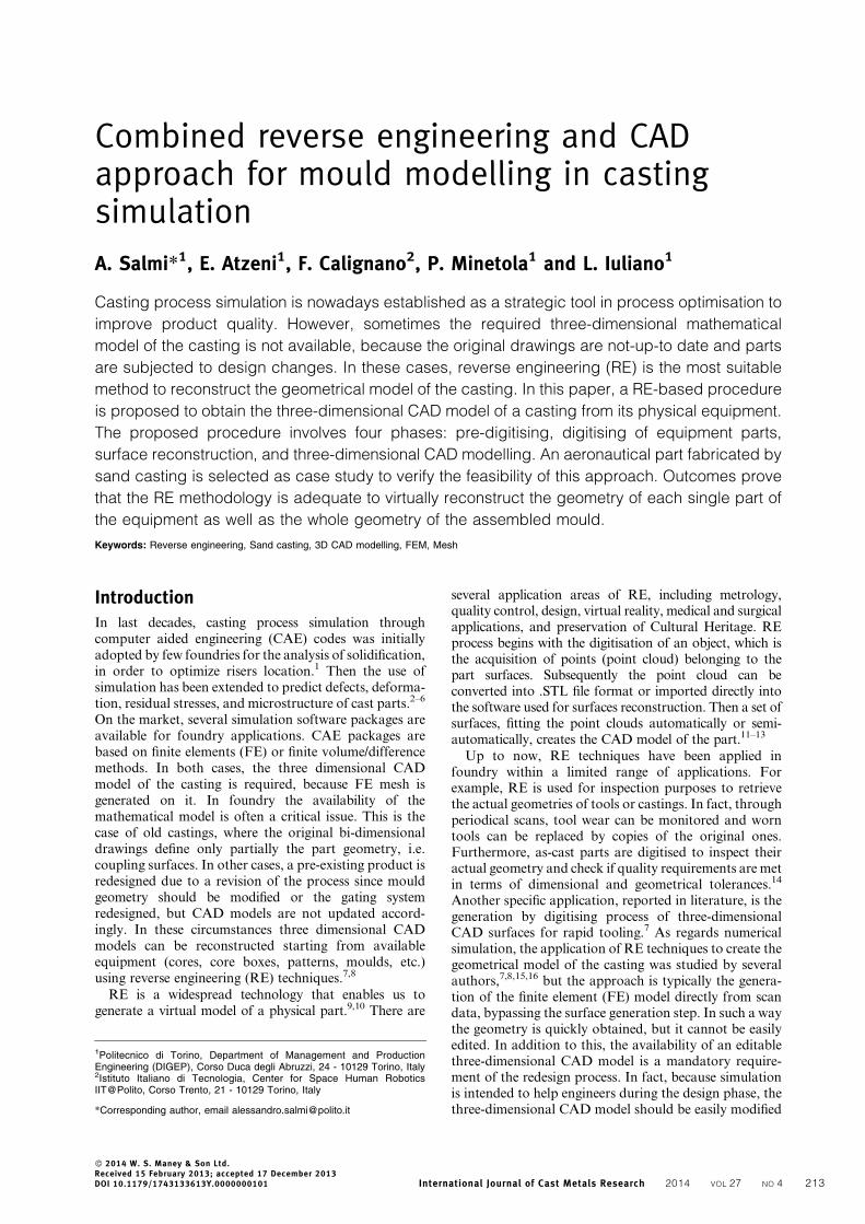
Case studyThe proposed procedure is validated on an existing sandcasting equipment for the production of an aeronauticalgearbox casing. The assembled mould consists of copeand drag parts, seven sand cores, thirteen chillers, fiveinsulation sleeves and one filter. The insulation sleevesand the filter are standard elements and the associated3D CAD models are provided by manufacturers,whereas the other parts have to be reconstructed. Inthis work, an ATOS Standard optical scanner is used fordigitisation. The scanning accuracy declared in thedevice data sheet is 0?05 mm. Each scan takes about8 s and retrieves as many as 400 000 points on the objectsurface within a scan area of 2006160 mm. Followingthe previously described RE procedure, the assembledmould is first subjected to pre-digitising to locate allparts of the assembly into a unique global referencesystem (Fig. 5). Four loops of the flow chart of Fig. 1are carried out to obtain sufficient data for thealignment of the parts. The time required for this firstphase is around 1 h and a half, as shown in Table 1.
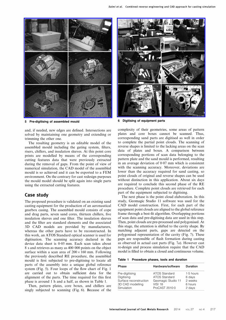
Then, pattern plates, core boxes, and chillers aresingly subjected to scanning (Fig. 6). Because of the
complexity of their geometries, some areas of patternplates and core boxes cannot be scanned. Thus,corresponding sand parts are digitised as well in orderto complete the partial point clouds. The scanning ofreverse shapes is limited to the lacking areas on the scandata of plates and boxes. A comparison betweencorresponding portions of scan data belonging to thepattern plate and the sand mould is performed, resultingin an average deviation of 0?07 mm which is consistentwith the scanning accuracy. Moreover, deviations arelower than the accuracy required for sand casting, sopoint clouds of original and reverse shapes can be usedwithout distinction in this application. About six daysare required to conclude this second phase of the REprocedure. Complete point clouds are retrieved for eachpart of the equipment subjected to digitising.
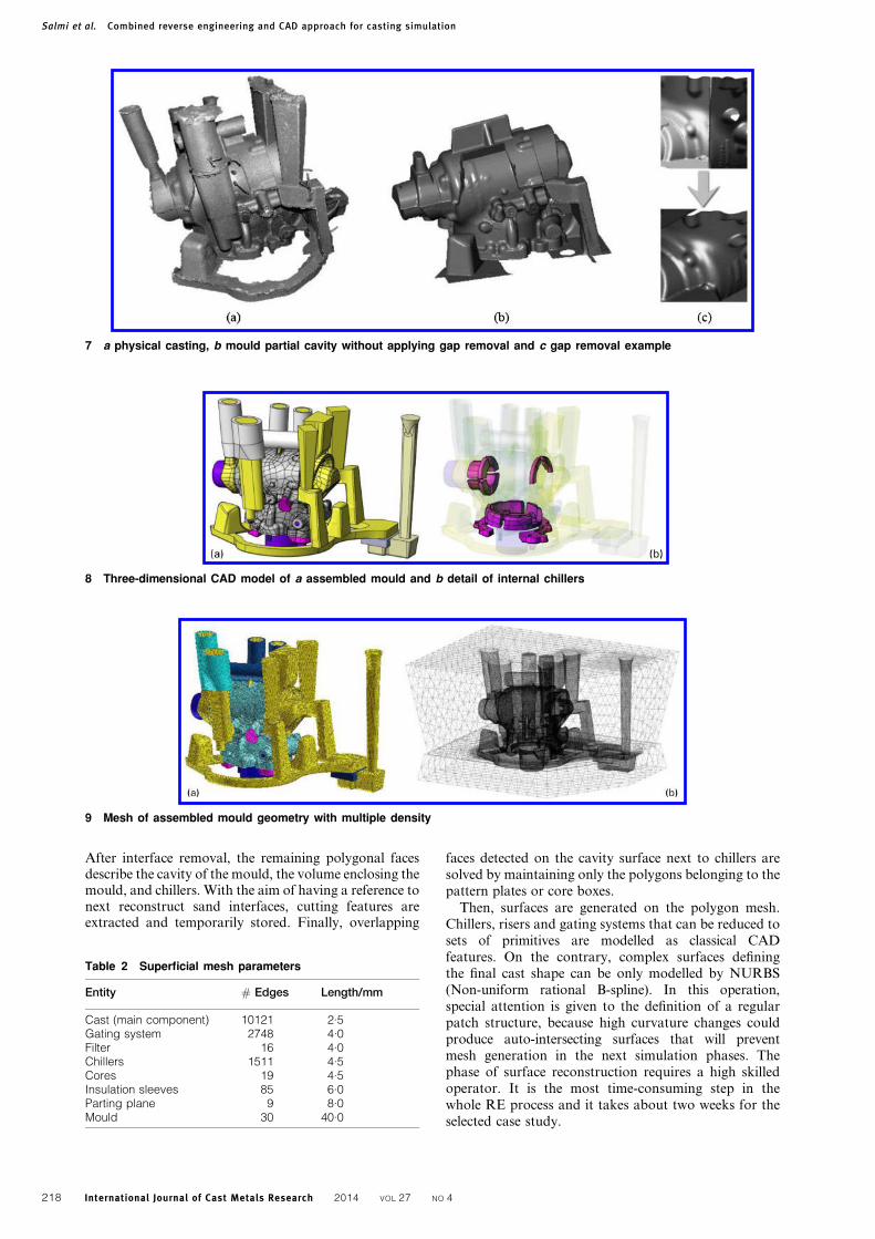
The next phase is the point cloud elaboration. In thisstudy, Geomagic Studio 11 software was used for theCAD model construction. First, for each part of theequipment point clouds are aligned to the global referenceframe through a best-fit algorithm. Overlapping portionsof scan data and pre-digitising data are used in this step.Then, point clouds are pre-processed and polygonised. Atthis stage, the attention is shifted to the cavity shape. Bymatching adjacent parts, gaps are detected on thepolygonised representation of the cavity (Fig. 7). Thesegaps are responsible of flash formation during castingas observed in actual cast parts (Fig. 7a). However castre-design and process simulation require that the CADmodel is filled to obtain a closed and continuous volume.
5 Pre-digitising of assembled mould
Table 1 Procedure phases, tools and duration
Phase Hardware/software Duration
Pre-digitising ATOS Standard 1.5 hoursDigitising ATOS Standard 6 daysSurface reconstruction Geomagic Studio 11 2 weeks3D CAD modelling VISI 18 6 hoursSimulation ProCAST 2010.0 2 days
6 Digitising of equipment parts
Salmi et al. Combined reverse engineering and CAD approach for casting simulation
International Journal of Cast Metals Research 2014 VOL 27 NO 4 217
After interface removal, the remaining polygonal facesdescribe the cavity of the mould, the volume enclosing themould, and chillers. With the aim of having a reference tonext reconstruct sand interfaces, cutting features areextracted and temporarily stored. Finally, overlapping
faces detected on the cavity surface next to chillers aresolved by maintaining only the polygons belonging to thepattern plates or core boxes.
Then, surfaces are generated on the polygon mesh.Chillers, risers and gating systems that can be reduced tosets of primitives are modelled as classical CADfeatures. On the contrary, complex surfaces definingthe final cast shape can be only modelled by NURBS(Non-uniform rational B-spline). In this operation,special attention is given to the definition of a regularpatch structure, because high curvature changes couldproduce auto-intersecting surfaces that will preventmesh generation in the next simulation phases. Thephase of surface reconstruction requires a high skilledoperator. It is the most time-consuming step in thewhole RE process and it takes about two weeks for theselected case study.
7 a physical casting, b mould partial cavity without applying gap removal and c gap removal example
8 Three-dimensional CAD model of a assembled mould and b detail of internal chillers
9 Mesh of assembled mould geometry with multiple density
Table 2 Superficial mesh parameters
Entity # Edges Length/mm
Cast (main component) 10121 2.5Gating system 2748 4.0Filter 16 4.0Chillers 1511 4.5Cores 19 4.5Insulation sleeves 85 6.0Parting plane 9 8.0Mould 30 40.0
Salmi et al. Combined reverse engineering and CAD approach for casting simulation
218 International Journal of Cast Metals Research 2014 VOL 27 NO 4

Finally, all the surfaces are imported into VISI 18 (VeroSoftware Limited) CAD environment for the assemblingwith standard geometries, such as filter and insulationsleeves. Again, filter and sleeves are overlapping cavitysurfaces. A simplification is made by deleting reconstructedsurfaces while maintaining the CAD ones. Whereas, eachsleeve that is included in or exceeding the volume enclosingthe mould is extended or trimmed by the mould surface.
After that operation, the geometry of the assembledmould is completely defined (Fig. 8). In order to have a
model adequate for casting simulation, core prints aremodelled via CAD on the basis of the interface featurespreviously extracted. The splitting of the cope and dragmould halves is also accomplished, whereas subdivisionsinside each mould half are less important from asimulation perspective. If needed for cast redesign,subdivisions can be made subsequently to obtain thecomplete CAD model of the assembled mould. Three-dimensional CAD modelling phase takes about 6 h.
The 3D CAD model of the assembled mould isimported into ProCAST, an FE software suite by ESIGroup for casting simulation. The link between theCAD model and the mesh is the 3D tetrahedral meshgenerator, which includes a CAD analysis module. Amultiple density mesh (Fig. 9 and Table 2) is created toimprove the simulation in terms of running time andaccuracy of results. The analysis of the mesh (Fig. 10)shows an aspect ratio below 32 (about 90% below 4), adihedral angle ranging from 71 to 172 deg, and radiiratio of 70% of elements greater than 0?6 proving thatthe obtained tetrahedral mesh has an high quality.
Simulation is then performed by setting A357aluminium alloy and a filling condition obtained fromreal pouring data (variable metal flowrate). Commonvalues of heat transfer coefficients for sand castingprocess of aluminium alloys are taken from ProCASTlibrary. Filling, solidification and stress analyses arefinally executed and completed without any convergenceerror.
ConclusionsThe mathematical CAD model is the starting point tosimulate the casting process for pre-existing parts foroptimization or redesign purposes. Nevertheless, it iswell known that in foundry the availability of the 3DCAD model of a product and the one of thecorresponding equipment is often lacking or notconstantly updated to reflect design changes. To over-come this problem, in this work an innovative RE-basedprocedure is proposed to obtain the actual geometry of acasting from the related physical equipment. Theprocedure involves four phases: pre-digitising, digitisingof single parts, surface reconstruction, and three-dimensional CAD modelling. The procedure is thenvalidated on the casting equipment for the fabricationby sand casting of an aeronautical part. Results provethat this RE approach is adequate to virtually recon-struct the geometry of each single part of the equipmentas well as the whole geometry of the assembled mould.The whole procedure is time consuming and the longestphase is the surface reconstruction from scan data. Forthis case study the assembled mould is composed of 28parts and it takes three to four weeks to complete theRE process. The achieved 3D CAD model is demon-strated to be suitable for CAE analysis and it is easilyeditable to adapt the design according to numericaloutputs.
Acknowledgements
The authors would like to acknowledge the assistance ofMr Giovanni Marchiandi and Dr. Fabrizio Bonaviaduring the digitising operations and modelling in thisstudy. Moreover the authors extend their thanks to DrAlessandro Ghio and Dr Giuseppe Argentieri (Avio
10 Mesh quality plot
Salmi et al. Combined reverse engineering and CAD approach for casting simulation
International Journal of Cast Metals Research 2014 VOL 27 NO 4 219

SpA, Torino, Italy) and to Dr Lorenzo Valente and DrCristian Viscardi (ECOTRE sas, Brescia, Italy) for theirhelp and support in the research. Financial support tothis work provided by the Piemonte Regional projectGReen Engine for Air Transportation 2020 (GREAT2020) is gratefully acknowledged.
References1. F. Shehata and M. Abd-Elhamid: Mater. Des., 2003, 24, (8), 577–
583.
2. L. Bichler and C. Ravindran: Mater. Des., 2010, 31, (Suppl. 1),
S17–S23.
3. A. Kermanpur, S. Mahmoudi and A. Hajipour: J. Mater. Process.
Technol., 2008, 206, (1–3), 62–68.
4. Z. Sun, H. Hu and X. Chen: J. Mater. Process. Technol., 2008, 199,
(1–3), 256–264.
5. J. Olofsson: Int. J. Cast Met. Res., 2012, 25, (6), 319–327.
6. I. Ohnaka, J. D. Zhu, N. Sako, A. Sugiyama and C. K. Ye: Int. J.
Cast Met. Res., 2011, 24, (3–4), 133–138.
7. J. C. Ferreira and N. F. Alves: J. Mater. Process. Technol., 2003,
142, (2), 374–382.
8. M. Sokovic and J. Kopac: J. Mater. Process. Technol., 2006, 175,
(1–3), 398–403.
9. A. Durupt, S. Remy and W. Derigent: ‘From a 3D point cloud to a
real CAD model of mechanical parts, a product knowledge based
approach’, in ‘Global design to gain a competitive edge’, (ed. X.-T.
Yan et al.), 805–813; 2008, London, Springer.
10. L. Iuliano and P. Minetola: Int. J. Adv. Manuf. Technol., 2009, 43,
(5), 551–562.
11. A. Chant, D. Wilcock and D. Costello: Int. J. Adv. Manuf.
Technol., 1998, 14, (1), 65–69.
12. C.-C. Tai and M.-C. Huang: Int. J. Mach. Tools Manuf., 2000, 40,
(13), 1913–1927.
13. T. Varady, R. R. Martin and J. Cox: Comp.-Aided Des., 1997, 29,
(4), 255–268.
14. P. Minetola, L. Iuliano and G. Argentieri: Int. J. Cast Met. Res.,
2012, 25, (1), 38–46.
15. M. Wu, J. Tinschert, M. Augthun, I. Wagner, J. Schadlich-
Stubenrauch, P. R. Sahm and H. Spiekermann: Dental Mater.,
2001, 17, (2), 102–108.
16. T. Suresh Babu and R. D. Thumbanga: Int. J. Mech., 2011, 5, (1),
40–47.
17. D. M. Yu, X. J. Li, Y. Xiong, Z. H. Gao and D. Wang: Key Eng.
Mater., 2011, 458, 368–373.
18. L. Iuliano, P. Minetola and A. Salmi: Measurement Sci. Technol.,
2010, 21, 105102–105114.
19. T. Varady, M. A. Facello and Z. Terek: Comp.-Aided Des., 2007,
39, (5), 379–388.
20. H. Edelsbrunner, J. Harer and A. Zomorodian: ‘Hierarchical
morse complexes for piecewise linear 2-manifolds’, Proc. 17th
Annual Symp. on ‘Computational geometry’, Medford, MA, USA,
June 2001, ACM, 70–79.
21. H. Edelsbrunner, D. Letscher and A. Zomorodian: ‘Topological
persistence and simplification’, Proc. 41st Annual Symp. on
‘Foundations of computer science’, Redondo Beach, CA, USA,
November 2000, IEEE Computer Society, 454.
Salmi et al. Combined reverse engineering and CAD approach for casting simulation
220 International Journal of Cast Metals Research 2014 VOL 27 NO 4