combined utilities enclosures - telstra · combined utilities enclosures ... combined utilities...
TRANSCRIPT
Combined Utilities Enclosures
TELSTRA CORPORATION LIMITED (ABN 33 051 775 556) | PRINTED 11/10/13 FINAL| TELSTRA UNRESTRICTED | 010062 | COMBINED UTILITIES ENCLOSURES
PAGE 1/18
Author’s name
Business unit
Telstra Operations
Sub-business unit
Access Technology Planning
Issue date
10 October 2013
Issue number
5
Telstra ID
010062
Summary
This specification sets out Telstra’s requirements for the design and manufacture of any combined utilities enclosure intended as an external housing for Telstra cabling or equipment at a single dwelling unit (house).
Combined Utilities Enclosures (continued)
TELSTRA CORPORATION LIMITED (ABN 33 051 775 556) | PRINTED 11/10/13 FINAL| TELSTRA UNRESTRICTED | 010062 | COMBINED UTILITIES ENCLOSURES
PAGE 2/18
Contents
1 Purpose 3
2 Scope 3
3 Requirements 3
3.1 Introduction 3
3.2 Overall dimensions 3
3.3 Space for Telstra equipment 4
3.4 Drainage 4
3.5 Door 4
3.6 Mounting panel (backboard) 4
3.7 AS/NZS 3012 compliance 5
3.8 Conduit/Cable entry holes 6
3.8.1 Hole size 6
3.8.2 Hole locations 6
3.8.3 Conduit connection 6
3.8.4 Protection of conduit and cables 7
3.9 Earthing 10
3.10 Materials 10
3.11 Documentation 10
4 Telstra equipment dimensions 10
4.1 General 10
4.2 Standard telephone/coaxial cable wall boxes 11
4.3 Network Termination Device (NTD) 12
4.4 Optical Network Termination (ONT) 13
5 TYPICAL INSTAllation 14
6 References 16
7 Definitions 16
8 Document control sheet 18

Combined Utilities Enclosures (continued)
TELSTRA CORPORATION LIMITED (ABN 33 051 775 556) | PRINTED 11/10/13 FINAL| TELSTRA UNRESTRICTED | 010062 | COMBINED UTILITIES ENCLOSURES
PAGE 3/18
1 PURPOSE
This specification sets out Telstra’s requirements for the design and manufacture of any combined utilities enclosure intended as an external housing for Telstra cabling or equipment at a single dwelling unit (house).
This document may be accessed on the Telstra Smart Community® web site www.telstra.com.au/smartcommunity/ (look under “Builders”).
2 SCOPE
This specification applies to residential premises where the metering or connection facilities for public
utilities are housed in a common enclosure at the building entry point.
This specification must be met to ensure that Telstra can use the enclosure to house the Telstra equipment.
3 REQUIREMENTS
3.1 Introduction
A combined utilities enclosure (CUE) allows the cabling and equipment associated with public utilities (e.g. electricity, telephone, gas and water) to be housed in a single, compartmentalised enclosure. This improves the overall appearance of the premises, improves access by service personnel, simplifies possible remote utilities metering via the telecommunications service at some future time, and assists in standardising installation practices. A typical CUE installation is depicted in Figure 10.
Where a CUE is to be used, it must be provided by the builder or electrician, usually during construction. For any CUE to be acceptable for Telstra’s use, it must comply with the minimum requirements set out in this specification. These requirements are not intended to prevent manufacture of any CUE that does not comply with Telstra’s requirements; however, Telstra may not be able to use a non-compliant CUE for technical or safety reasons.
Notwithstanding anything contained in this specification:
there is no guarantee of acceptance by Telstra;
Telstra reserves the right to vary this specification at any time;
Telstra may agree to use a CUE that does not comply with this specification.
3.2 Overall dimensions
The overall internal dimensions of the telecommunications compartment of the CUE should not be less
than 480 mm wide x 415 mm high x 200 mm deep to accommodate equipment for fibre to the premises
(FTTP) technology.
Allowance is made for a smaller telecommunications compartment to accommodate equipment for
technologies other than FTTP or to support FTTP technologies where the FTTP equipment is installed
inside the building.
Note: Where a smaller telecommunications compartment is provided and it is necessary to install
external FTTP equipment, such equipment may need to be installed on the wall beside the CUE.
Detailed requirements are set out in 3.3 to 3.11.
® Registered trade mark of Telstra Corporation Limited ABN 33 051 775 556

Combined Utilities Enclosures (continued)
TELSTRA CORPORATION LIMITED (ABN 33 051 775 556) | PRINTED 11/10/13 FINAL| TELSTRA UNRESTRICTED | 010062 | COMBINED UTILITIES ENCLOSURES
PAGE 4/18
3.3 Space for Telstra equipment
The space for Telstra equipment, exclusive of the mounting panel (backboard) and any obstructions, protrusions, turned edges, bolts, screws, hinges, etc., shall not be less than:
(a) in the case of a combined enclosure for electricity and telecommunications only, 480 mm wide x 415 mm high x 140 mm deep; or
(b) in the case of a combined enclosure for electricity, telecommunications and gas/ water, 480 mm wide x 310 mm high x 140 mm deep (see Note 1).
Notes:
1. An enclosure that complies with (b) may not support housing of current or future fibre-to-the-premises (FTTP) equipment (see Figure 9).
2. Where any part of the enclosure intrudes into the space bound by the above dimensions, the supplier or manufacturer will need to satisfy Telstra that the intrusion will not obstruct the installation of, or safe access to, any Telstra connection device.
The dimensions of common Telstra connection devices are provided in section 4.
3.4 Drainage
The bottom shelf of the telecommunications compartment shall provide for drainage of any condensed water, or any water that may run down a cable entering from above the compartment or that may be ducted into the compartment via a conduit. Normally this will require the bottom shelf to slope towards the front with drainage holes that drain the water to the ground or to an external channel in the enclosure.
3.5 Door
A separate, ventilated hinged door should be provided to access the telecommunications compartment. For an enclosure that complies with 3.3 (a), the door aperture shall be at least 375 mm wide x 375 mm high. For an enclosure that complies with 3.3 (b), the door aperture shall be at least 375 mm wide x 270 mm high.
If the door is not separate, the partition between the telecommunications compartment and any other utility compartment shall extend to the full depth of the enclosure except for any indentation required for the passage of a flexible power cord in compliance with AS/NZS 3012 (see 3.7).
The door:
(a) shall have a latch and closure stop mechanisms; and (b) shall open at least 90°; and (c) should be removable.
3.6 Mounting panel (backboard)
The telecommunications compartment shall contain an easily removable, 18 mm to 20 mm thick mounting panel (backboard), which:
(a) is at least 400 mm wide; (b) is positioned at least 20 mm below the internal surface of top of the enclosure compartment and
at least 30 mm above the internal surface of the bottom of the enclosure compartment; (c) for an enclosure that complies with 3.3 (a), extends at least 350 mm below the horizontal plane
of the top edge of the door aperture; (d) for an enclosure that complies with 3.3 (b), extends at least 260 mm below the horizontal plane
of the top edge of the door aperture; (e) is capable of being drilled and screwed using self-tapping screws; (f) has at least 40 mm access space behind the panel except for any steel barrier described in
3.8.4, in which case a minimum clearance of 20 mm shall be provided between the barrier and the rear of the panel; and
(g) is electrically non-conductive and impervious to moisture.

Combined Utilities Enclosures (continued)
TELSTRA CORPORATION LIMITED (ABN 33 051 775 556) | PRINTED 11/10/13 FINAL| TELSTRA UNRESTRICTED | 010062 | COMBINED UTILITIES ENCLOSURES
PAGE 5/18
3.7 AS/NZS 3012 compliance
Provision may be made for the passage of one or more power cords through the telecommunications compartment during house construction in compliance with AS/NZS 3012.
Notes:
1. The above illustrates some of the dimensions described in 3.2 to 3.6.
2. Any electrical conduit passing through telecommunications compartment behind the mounting panel must be mechanically protected from damage by drills or screw fastenings by means of a steel cover plate that must be set back from the mounting panel by at least 20 mm for the passage of telecommunications cables (see 3.8.4).
Figure 1 Minimum dimensions for the telecommunications compartment
140
200
Enclosure door
Mounting panel
Cable well
40
18
20
Bottom sloped for drainage
30
20
Door opening at least 375 mm
(or 270 mm) high (see clause 3.5)
Mounting panel to extend at least
350 mm (or 260 mm) below the top edge of
the door opening (see clause 3.6)
Telstra equipment
Steel cover strip for any electrical conduit through the compartment (Note 2)
All dimensions in mm
Combined Utilities Enclosures (continued)
TELSTRA CORPORATION LIMITED (ABN 33 051 775 556) | PRINTED 11/10/13 FINAL| TELSTRA UNRESTRICTED | 010062 | COMBINED UTILITIES ENCLOSURES
PAGE 6/18
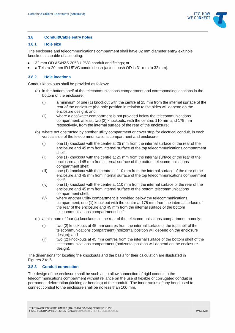
3.8 Conduit/Cable entry holes
3.8.1 Hole size
The enclosure and telecommunications compartment shall have 32 mm diameter entry/ exit hole knockouts capable of accepting:
32 mm OD AS/NZS 2053 UPVC conduit and fittings; or
a Telstra 20 mm ID UPVC conduit bush (actual bush OD is 31 mm to 32 mm).
3.8.2 Hole locations
Conduit knockouts shall be provided as follows:
(a) in the bottom shelf of the telecommunications compartment and corresponding locations in the bottom of the enclosure:
(i) a minimum of one (1) knockout with the centre at 25 mm from the internal surface of the rear of the enclosure (the hole position in relation to the sides will depend on the enclosure design); and
(ii) where a gas/water compartment is not provided below the telecommunications compartment, at least two (2) knockouts, with the centres 110 mm and 175 mm respectively, from the internal surface of the rear of the enclosure;
(b) where not obstructed by another utility compartment or cover strip for electrical conduit, in each vertical side of the telecommunications compartment and enclosure:
(i) one (1) knockout with the centre at 25 mm from the internal surface of the rear of the enclosure and 45 mm from internal surface of the top telecommunications compartment shelf;
(ii) one (1) knockout with the centre at 25 mm from the internal surface of the rear of the enclosure and 45 mm from internal surface of the bottom telecommunications compartment shelf;
(iii) one (1) knockout with the centre at 110 mm from the internal surface of the rear of the enclosure and 45 mm from internal surface of the top telecommunications compartment shelf;
(iv) one (1) knockout with the centre at 110 mm from the internal surface of the rear of the enclosure and 45 mm from internal surface of the bottom telecommunications compartment shelf;
(v) where another utility compartment is provided below the telecommunications compartment, one (1) knockout with the centre at 175 mm from the internal surface of the rear of the enclosure and 45 mm from the internal surface of the bottom telecommunications compartment shelf;
(c) a minimum of four (4) knockouts in the rear of the telecommunications compartment, namely:
(i) two (2) knockouts at 45 mm centres from the internal surface of the top shelf of the telecommunications compartment (horizontal position will depend on the enclosure design); and
(ii) two (2) knockouts at 45 mm centres from the internal surface of the bottom shelf of the telecommunications compartment (horizontal position will depend on the enclosure design).
The dimensions for locating the knockouts and the basis for their calculation are illustrated in Figures 2 to 6.
3.8.3 Conduit connection
The design of the enclosure shall be such as to allow connection of rigid conduit to the telecommunications compartment without reliance on the use of flexible or corrugated conduit or permanent deformation (kinking or bending) of the conduit. The inner radius of any bend used to connect conduit to the enclosure shall be no less than 100 mm.

Combined Utilities Enclosures (continued)
TELSTRA CORPORATION LIMITED (ABN 33 051 775 556) | PRINTED 11/10/13 FINAL| TELSTRA UNRESTRICTED | 010062 | COMBINED UTILITIES ENCLOSURES
PAGE 7/18
3.8.4 Protection of conduit and cables
Any telecommunications conduit passing through the electricity compartment shall be able to be protected by means of a steel barrier plate.
Any electricity or other service conduit or pipe passing through telecommunications compartment behind the mounting panel shall be mechanically protected from damage by drills or screw fastenings by means of a steel barrier plate, which shall be set back from the rear of the mounting panel by at least 20 mm for the passage of telecommunications cables.
Notes:
1. Only a side elevation of the compartment is shown in this diagram and the following diagrams to demonstrate the rationale for the hole spacing. Refer to 3.8.1 to 3.8.4 for conduit entry hole requirements for the sides, top, bottom and rear of the enclosure.
2. The holes that are useable for conduit entries in the particular case illustrated are shaded in each diagram. Where conduit entry to the rear of the enclosure is also possible, this is indicated on the diagram. The holes with the centres spaced at 175 mm from the rear of the enclosure are not required in the top of the enclosure, nor are they required on the sides of the enclosure if this access is provided in the bottom of the enclosure.
3. The above installation arrangement is considered to be the most common, e.g. enclosure secured to the face of the wall studs for brick veneer construction.
Figure 2 Conduit entry holes — brick veneer or double brick Enclosure secured to the face of the studs or internal brick
25
Telecommunications compartment Stud
25
175
Cavity conduit entry
45
45 Rear conduit entry
Brick
Brick
Surface conduit entry (bottom or sides only)
Note 2
110
110
All dimensions in mm

Combined Utilities Enclosures (continued)
TELSTRA CORPORATION LIMITED (ABN 33 051 775 556) | PRINTED 11/10/13 FINAL| TELSTRA UNRESTRICTED | 010062 | COMBINED UTILITIES ENCLOSURES
PAGE 8/18
Figure 4 Conduit entry holes — single brick
Rear of the enclosure flush with the internal brick face
Surface conduit entry (at bottom or side using bend)
Rear conduit entry
Telecommunications compartment
Brick
Brick
Figure 3 Conduit entry holes — brick veneer
Enclosure secured between studs
Stud
Cavity conduit entry
Cavity conduit entry
(bottom shelf only)
Brick
Brick
Telecommunications compartment

Combined Utilities Enclosures (continued)
TELSTRA CORPORATION LIMITED (ABN 33 051 775 556) | PRINTED 11/10/13 FINAL| TELSTRA UNRESTRICTED | 010062 | COMBINED UTILITIES ENCLOSURES
PAGE 9/18
Figure 6 Conduit entry holes
Enclosure secured to the surface of the wall
Telecommunications compartment
Surface conduit entry
Rear conduit entry
Brick
Figure 5 Conduit entry holes — single brick
Rear of the enclosure proud of the internal brick face
External conduit entry (bottom or side only)
Internal conduit entry
Telecommunications compartment
Brick
Brick

Combined Utilities Enclosures (continued)
TELSTRA CORPORATION LIMITED (ABN 33 051 775 556) | PRINTED 11/10/13 FINAL| TELSTRA UNRESTRICTED | 010062 | COMBINED UTILITIES ENCLOSURES
PAGE 10/18
3.9 Earthing
A 6 mm2 green/yellow equipotential bonding conductor shall be provided to the electricity compartment
(or direct-bonding techniques may be used if complying with all regulations) for connection by the electrician to the main earthing bar or main earthing conductor.
The bonding conductor shall be long enough to reach the furthest extremity of the telecommunications compartment and shall be labelled in both the electricity compartment and the telecommunications compartment in accordance with the requirements of the Australian/New Zealand Wiring Rules (AS/NZS 3000) and the ACMA Wiring Rules (AS/ACIF S009).
The bonding conductor should preferably terminate on a readily accessible Communications Earth Terminal (CET) within the telecommunications compartment.
3.10 Materials
All materials and finish shall be of good quality to acceptable industry standards of workmanship and be suitable for the task and life normally expected.
Any chemical in the form of residue remaining, enclosure material or finish shall have a Material Safety Data Sheet, which shall be supplied to Telstra.
3.11 Documentation
If the manufacturer or supplier requires Telstra verification that a CUE complies with this specification, identified/numbered, scaled, dimensioned drawings, and preferably 3-D views, should be provided to Telstra. Soft copies of the drawings are desired (for possible inclusion in Telstra documentation). CAD drawings should be saved as Jpeg (.JPG) or Windows Metafile (.WMF) files.
4 TELSTRA EQUIPMENT DIMENSIONS
4.1 General
Telstra uses several types of connection device on the external wall of most houses for the purpose of interfacing the underground or aerial lead-in cabling to the internal cabling. The connection devices that Telstra used at the time of writing are described in 4.2 to 4.4.
Telstra may change the type of external connection device it uses for any purpose at any time.

Combined Utilities Enclosures (continued)
TELSTRA CORPORATION LIMITED (ABN 33 051 775 556) | PRINTED 11/10/13 FINAL| TELSTRA UNRESTRICTED | 010062 | COMBINED UTILITIES ENCLOSURES
PAGE 11/18
4.2 Standard telephone/coaxial cable wall boxes
Telstra uses the same type of wall box for telephone (twisted pair) cable connections and FOXTEL/BigPond coaxial cable connections.
Figure 7 shows the dimensions (in mm) of the Telstra wall box that is used for these purposes and the required clearances for access.
Two such boxes may need to be housed in the CUE (i.e. one each for twisted pair cables and coaxial cables).
Notes:
1. Identical wall boxes may be used for separate housing of twisted pair and coaxial cable connections. The cover of the wall box for twisted pair cables is secured by a standard screw while the wall box for coaxial cables uses a security screw fastening.
2. Two such boxes may be required to be installed in the telecommunications compartment of the CUE.
Figure 7 Standard telephone cable wall box or FOXTEL/BigPond coaxial cable
isolation box and required access space
250
200
CAUTION HAZARDOUS VOLTAGE
MAY EXIST INSIDE UNAUTHORISED ACCESS
IS PROHIBITED
80
215
30 136 34 63
Front Side
35
30
250
200
170

Combined Utilities Enclosures (continued)
TELSTRA CORPORATION LIMITED (ABN 33 051 775 556) | PRINTED 11/10/13 FINAL| TELSTRA UNRESTRICTED | 010062 | COMBINED UTILITIES ENCLOSURES
PAGE 12/18
4.3 Network Termination Device (NTD)
Figure 8 shows the dimensions (in mm) of a Telstra NTD that is used for connection of twisted pair cables and the required clearances for access.
An NTD may need to be housed in the CUE with one of the wall boxes described in 4.2.
Note: The minimum space required for NTD access is indicated by the shaded area. At least 40 mm clearance is required to the left of the NTD to open the cover 90° and at least 60 mm clearance is required to the right of the NTD to disengage the cover clip by hand. A minimum of 40 mm is required below the NTD for cable access.
Figure 8 Telstra network termination device and required access space
250
260
40
300
60
350 80
72
Front Side
300
285
260
60
350
40

Combined Utilities Enclosures (continued)
TELSTRA CORPORATION LIMITED (ABN 33 051 775 556) | PRINTED 11/10/13 FINAL| TELSTRA UNRESTRICTED | 010062 | COMBINED UTILITIES ENCLOSURES
PAGE 13/18
4.4 Optical Network Termination (ONT)
Figure 9 shows the dimensions (in mm) of a Telstra ONT used for Fibre To The Premises (FTTP) installations and the required ventilation and access clearances.
Note: The minimum space required for ONT access is indicated by the shaded area. At least 65 mm clearance is required to the left of the ONT to open the cover 90° and at least 30 mm clearance is required to the right of the ONT to disengage the cover clips by hand. A minimum of 50 mm is required below the NTD for cable access.
Figure 9 Telstra FTTP ONT and required access space
30565
415
50
400
345
20
30
Front
TELCO
NTD
Property of Telstra
N594
Side
11030
140
30565
415
50
345
20
30
TELCO
400

Combined Utilities Enclosures (continued)
TELSTRA CORPORATION LIMITED (ABN 33 051 775 556) | PRINTED 11/10/13 FINAL| TELSTRA UNRESTRICTED | 010062 | COMBINED UTILITIES ENCLOSURES
PAGE 14/18
5 TYPICAL INSTALLATION
Figure 10 Typical combined utilities enclosure installation (see Notes overleaf)
Gutter
Fascia
Soffit (eaves) lining
Soffit (eaves)batten - maybe dril led
Ceiling lining
Bottom plate (may benotched if necessary)
Skirting
Nogging(may be dril led)
Wall l ining
Stud (load bearing andshould not be dril led)
Earth electrode (part of electricity installation)Floor slab
Vapour barrier
Strip footing
Cornice
Top plate (load bearingand must not be dril led)
Minimum bend radius 100 mm
Electricity compartment(meters and/or switchboard)
Gas/water compartment(optional)
Flashing
Wall cavity 25 - 50 mm(nominally 40 mm)
Telecommunications compartment
Telstra wall box/es (insidetelecommunications compartment)Cable well behind backboard
Remov able backboard
Roof cavity
Eaves cavity
Tiles
Roof batten
radius 300 mmMinimum bend
minimum 20 mm ID
Telstra lead-in conduit
(internal diameter)
Weephole
or
Surface 20 mm ID Telstra lead-in conduit(where concealed conduit not prov ided)
Concealed 20 mm ID Telstra lead-inconduit (installed before footingsare laid) passing through gas/watercompartment (if present)
Cable/s
or
Surface 20 mm ID conduit to roof space(where concealed conduit not prov ided)
Concealed 20 mm ID conduit to roofspace (installed at frame stage), runthrough electrical compartment, orto rear or either side of enclosure,depending on enclosure design,location and building constraints
Roof truss(load bearing - must not be dril led)
300 mm radius bend

Combined Utilities Enclosures (continued)
TELSTRA CORPORATION LIMITED (ABN 33 051 775 556) | PRINTED 11/10/13 FINAL| TELSTRA UNRESTRICTED | 010062 | COMBINED UTILITIES ENCLOSURES
PAGE 15/18
Notes:
1. The principles depicted in the diagram on the preceding page apply equally to brick veneer and cavity brick (e.g. double brick) construction. The cavity width is normally between 25 mm and 50 mm with brick veneer, and between 40 mm and 100 mm with full brick construction. Some solid masonry walls may not have a cavity, in which case the surface conduit option would be used.
2. All conduit and bends are white UPVC (rigid PVC), with a minimum nominal inside diameter (ID) of 20 mm (actual inside diameter of 23.65 mm or greater).
3. With two storey dwellings, the draw conduit is run into the roof space, not the ceiling space for the lower storey.
4. The cooperation of the builder is required for the lead-in conduit and draw conduit to be concealed. Telstra will install surface conduit where the opportunity to conceal the conduit has been missed. In some cases, this will require installation of a contoured bend around the footings thus:
5. The diagram is to scale and shows a single storey, brick veneer dwelling with roof tiles, 600 mm eaves
and slab-on-ground construction using strip footing. Examples of construction variables are:
cavity brick or concrete masonry walls;
weatherboard or fibre-cement sheet cladding;
rendered polystyrene cladding;
timber or metal frame;
metal sheet roof;
monolithic floor slab;
suspended floor;
two storey or high-set (e.g. suspended floor with room for parking, laundry, etc. underneath);
narrower eaves (e.g. 450 mm);
no eaves (fascia installed directly on brick);
gable end.
6. The termite barrier may be bridged or breached by the underground lead-in conduit. Common termite barriers are:
chemical — lead-in conduit breaches the barrier (i.e. passes through it);
exposed slab edge — lead-in conduit breaches the barrier (concealed conduit) or bridges the barrier (surface conduit);
stainless steel mesh, ant cap or other sheet material — lead-in conduit breaches the barrier (concealed conduit) or bridges the barrier (surface conduit);
graded stone — lead-in conduit breaches or bridges the barrier depending where the stone is used (cavity or building perimeter) and whether the conduit is concealed or surface-run..
For pre-wired installations, it is the builder's responsibility to maintain the efficacy of the termite barrier until building completion. For post-wired installations, the person who digs and reinstates the trench should arrange for reinstatement of the termite barrier if this is breached by the trench. This would normally be at the customer's expense.
Figure 10 Typical combined utilities enclosure installation (continued)
radius bendHalf of 300 mm
radius bendHalf of 300 mm
Conduit coupling (joiner)
Short length of conduit
radius bendHalf of 300 mm
radius bendHalf of 300 mm
Conduit coupling (joiner)
Short length of conduit
or

Combined Utilities Enclosures (continued)
TELSTRA CORPORATION LIMITED (ABN 33 051 775 556) | PRINTED 11/10/13 FINAL| TELSTRA UNRESTRICTED | 010062 | COMBINED UTILITIES ENCLOSURES
PAGE 16/18
6 REFERENCES
Document number Title
AS/ACIF S009 Installation requirements for customer cabling (ACMA Wiring Rules)
AS/NZS 2053 Conduits and fittings for electrical installations
AS/NZS 3000 Electrical installations (known as the Australian/New Zealand Wiring Rules)
AS/NZS 3012 Electrical installations — Construction and demolition sites
7 DEFINITIONS
Term Definition
ACMA Australian Communications and Media Authority
CAD computer aided design
CET Communications Earth Terminal (formerly called a bonding terminal) — a terminal block required as a testing and isolation point to connect the building electrical earthing system to earthing conductors used for telecommunications purposes
combined utilities enclosure (CUE) An electrical meter panel/switchboard enclosure that has a separate compartment for telecommunications equipment and, optionally, additional compartments for other utilities such as gas and water
FTTP Fibre To The Premises
ID inside diameter
JPG JPEG file (a file format for graphics)
mm millimetres
NTD Network Termination Device
OD outside diameter
ONT Optical Network Termination (used with FTTP)
public utilities the services and facilities required in a community to provide for public health, amenity and convenience, e.g. water supply, sewerage and drainage, electricity supply, gas supply, telephone

Combined Utilities Enclosures (continued)
TELSTRA CORPORATION LIMITED (ABN 33 051 775 556) | PRINTED 11/10/13 FINAL| TELSTRA UNRESTRICTED | 010062 | COMBINED UTILITIES ENCLOSURES
PAGE 17/18
Term Definition
services and garbage disposal

Combined Utilities Enclosures (continued)
TELSTRA CORPORATION LIMITED (ABN 33 051 775 556) | PRINTED 11/10/13 FINAL| TELSTRA UNRESTRICTED | 010062 | COMBINED UTILITIES ENCLOSURES
PAGE 18/18
8 DOCUMENT CONTROL SHEET
Issue number Issue date Details on the change
1 29 November, 1999
2 3 October, 2002
Sections 3.3, 3.4 & 3.9 amended plus minor updates (e.g. wall boxes)
3 7 September, 2005
Paragraph 3.5.2 (b)(v) added, Attachment A02 amended, minor edits
4 21 October, 2009
Reviewed, updated, attachments consolidated into main document
5 10 October, 2013
Converted document to current corporate template and logo; content unchanged