combining finite element and multibody modeling techniques
TRANSCRIPT

Combining Finite Element and Multibody Modeling Techniques for Time-EfficientSimulation of Nonlinear Gear Dynamics
Jakub Korta∗, Antonio Palermo†∗‡, Domenico Mundo∗ and Shadi Shweiki∗†∗University of Calabria, Department of Mechanical, Energy and Management Engineering,
Ponte Pietro Bucci, Cubo 46C, 87036 Rende, Italy†Siemens Industry Software NV, Interleuvenlaan 68, 3001 Leuven, Belgium
‡KU Leuven, Department of Mechanical Engineering, Celestijnenlaan 300 B, B-3001, Heverlee, Belgium
Email: [email protected], [email protected],[email protected], [email protected]
Abstract—Dynamics and vibroacoustics of mechanical transmis-sions are perceived as one of the major concerns in the contem-porary geared driveline design. These characteristics influencedurability and efficiency of the system, as well as its quality.However, due to strong local effects and system nonlinearities,computer analyses of gears can be extremely time consuming,and hence, in the industrial practice, are carried out only to somelimited extent. This paper describes a time-efficient multibodyapproach to this problem, which allows for fast analyses ofhigh fidelity, complex numerical gearbox models. The approachpresented in the paper consists of two phases: firstly, statictransmission error curves, describing the gear meshing stiffness,are derived by analyzing high fidelity Finite Element models ofthe gears; subsequently, time-efficient multibody simulations ofgear dynamics under different operating conditions are achievedby using a specifically defined user force element that allows totake the meshing stiffness variability into account thanks to thepreviously calculated static transmission curves.
Keywords–Gears; Mechanical Transmissions; Transmission Er-ror; Dynamics; Nonlinear Statics.
I. INTRODUCTION
The design of a drivetrain based on a gearbox requiresunderstanding of a number of different mechanical engineeringfields, among which material strength, fatigue, noise and vi-bration (NV) or manufacturing issues are particularly relevant.The contemporary methods used to support mechanical designprocess take advantage from numerical tools, which allow toprepare and test a number of alternatives in relatively shorttime and without the need of preparing expensive physicalprototypes. However, in the case of the mechanical transmis-sions, to obtain reliable and accurate results, it is required touse high fidelity, very detailed computational models. Thisdrives a need for accurate experimental campaigns, whichcould be used for model validation purposes. A descriptionof a modern gear test rig and a technique for measuring thetransmission error between two meshing gears can be found inRef. [1]. The difficulty in gear numerical modelling is drivenby the fact that the phenomena observed on the surface ofgear teeth are often local (e.g., Hertzian stress) and nonlinear(e.g., contact force moving along the tooth profile). The formerproblem is caused by high forces acting on a very small, curvedcontact surface of the teeth. High, Hertzian stress developslocally and causes local material deformation, which influencesthe teeth contact mechanics. The nonlinearities instead, canhave various sources, among which the most significant areconnected with the number of teeth staying in contact duringgear rotation (expressed by the so-called contact ratio number
- see Figure 1) and by nonlinear deflection of a tooth, whichis caused by contact force traveling along its profile, whichnormally has uneven thickness from the bottom, to the top.In particular, three-dimensional dynamic analyses aimed atassessing drivetrain NV characteristics are often very timeconsuming and require significant computational power. Toovercome this problem, it is common to describe the analyzedgears by simplified, one-dimensional or planar models [2][3] [4], which can cover the general behavior of the system,representing roughly its deflection caused by loading forces.In the same time, however, they neglect important phenomenainfluencing its performance: misalignments, shuttling or teethmicrogeometry modifications. These factors contribute consid-erably to dynamic loading of the gears, causing gear excitationand, as a consequence, system vibrations.
The term of misalignment refers to inaccuracies in gearrelative positioning, which result in unsymmetrical load dis-tribution on teeth surfaces. These positional errors can becaused by lack of parallelism between the shaft rotation axes,deflection of the mechanism components or manufacturingerrors (e.g., gear or shaft eccentricity). Shuttling, which isa fluctuation in the axial position of the resultant contactforce (i.e., along the rotation axis), leads to oscillations onbearing forces and dynamic moments in the plane of action(i.e., the plane spread over the contact force vectors, along theaxial direction). Shuttling happens intrinsically for gears withinclined teeth (i.e., helical gears), due to the traveling contactareas, from one corner of the tooth surface to the opposite,when the gears spin. Other reason can be due to shifts incontact stress distribution caused by gear misalignment [5].Microgeometry modifications (e.g., tip relief, crowning) areapplied often to the gears in order to improve the interactionbetween the teeth and to decrease local stress concentrationon the teeth edges [6]. In Ref. [7], the authors analyzed thedynamic characteristics of a gear pair, which was subjected toexcitation caused by external forces and geometry inaccuracy.This paper provides a wide theoretical insight into the geardynamics problem, proposing an analytical approach whichcan be used to solve it. The authors described also numericalcalculations, which were aimed at understanding the influenceof forcing parameters on the analyzed system. However, theproposed method does not rely on MB modelling technique,severely limiting its applicability in the industrial practice.
Other factors which should not be neglected when gearsare under NV analysis are the variable meshing stiffness andthe Transmission Error (TE). The former describes fluctuation
94Copyright (c) IARIA, 2015. ISBN: 978-1-61208-442-8
SIMUL 2015 : The Seventh International Conference on Advances in System Simulation

of gear pair stiffness and is caused by uneven load distributionamong the teeth during the gear rotational movement (seeFigure 1). It is governed by the gear contact ratio and isload dependent. Nonlinear stiffness encountered in mechanicaltransmissions was studied by using a piecewise representationin Ref. [8], which describes the analytical and numericalapproaches towards the solution for such problems. The TEis defined as a deviation from a perfect motion of gears,which can be caused by different reasons: misalignments,teeth deflection under load, manufacturing inaccuracies andothers. All these factors constitute for mechanical transmissioncomplex dynamic behavior and should be taken into accountduring the design phase. One approach to solve this problemis based on the Finite Element Method (FEM), which iscapable of solving accurately even the most complicated designcases. However, its major drawback, i.e., the simulation time,precludes its application to demanding problems analyzed inthe time domain. In Ref. [9], the authors took the endeavorto simulate gear interaction by using comprehensive FEMapproach and to tune specially prepared one degree-of-freedom(DoF) models, to be able to represent its complex nonlinearbehavior. As they reported in the paper, they were able toobtain either good correlation with the results in frequencydomain or satisfying meshing stiffness representation, but notboth simultaneously. Similar studies were described in Ref.[10], in which the authors took the efforts aimed at correlatingthe results from FEM-based and analytical, one DoF dynamicmodels with the experiments.
Figure 1. Analysis of gear rotation angle, for which one (A) and two (B)pairs of teeth stay in contact. Figures C and D show the teeth deflection
pattern, while local Hertzian stress is presented in figures E and F.
In this paper we present a numerical study on the dynamicsof a spur gear pair, which was carried out on a multibody(MB) model by implementation of a methodology reportedin Ref. [11] and [12]. The utilized approach is capable ofanalyzing complicated geared drivelines under variable loadsand operating conditions within computational time, which isorders of magnitude shorter than in the case of the adequate
FEM-based runs.The subsequent paragraphs describe the two phases of the
proposed simulation approach: firstly, static transmission error(STE) curves, describing the gear meshing stiffness, are de-rived by analyzing high fidelity finite element (FE) models ofthe gears; subsequently, time-efficient MB simulations of geardynamics under different operating conditions are achieved byusing a specifically defined user force element that allows totake the meshing stiffness variability into account thanks to thepreviously calculated static transmission curves. It is shownthat the utilized MB technique can be successfully used fordynamic simulation of gear meshing and is able to captureits nonlinear, load-dependent behavior. The described analyseswere carried out in velocity run-up conditions, for the modelsloaded by torque of variable values. Because of the requiredcomputational time, the same results would not be attainableusing the FEM approach.
Figure 2. Flowchart of the proposed methodology for gear dynamicsimulation.
The paper is structured in the following manner: SectionII summarizes the proposed approach, describing in short eachactivity which must be taken to carry out time-efficient gearboxsimulations. Section III provides a detailed description of theprepared FE model and provides a description of the mesh con-vergence analysis. Section IV presents and compares differentmethods of calculating the TE curves, allowing for choosingthe most efficient approach for STE estimation. Section Vdescribes the implementation of the described methodologyin order to understand the dynamic behavior of a spur gearpair in run-up conditions.
II. GEAR DYNAMIC SIMULATION METHODOLOGY
Based on the considerations presented in Section I, we cannow describe the methodology for gear dynamic simulations,which is proposed in this paper. For the sake of clarity, theflowchart of the simulation procedure is presented in Figure2. As mentioned above, the elaborated procedure is based onderivation of a STE curve, which is computed using FEMsimulations. As shown in the subsequent paragraphs, nonlinearstatic analyses are sufficient to describe the desired behaviorof the analyzed system. This operation is executed iteratively,for a set of discrete gear angular positions. Following, theSTE curve is derived by approximation of the results obtainedin the preceding phase. This constitutes an input for the MBsimulations, which are carried out on a MB model, preparedusing the contact formulation described in Ref. [11] and [12].
95Copyright (c) IARIA, 2015. ISBN: 978-1-61208-442-8
SIMUL 2015 : The Seventh International Conference on Advances in System Simulation

MB model prepared in this manner can be used for fast andaccurate dynamic simulations of complex gear trains, requiringrelatively short computation time.
III. FE MODELING AND ANALYSIS OF THE SIMULATEDSYSTEM
The analyses described in this paper were carried out ona pair of meshing, high-precision, identical spur gears, withinvolute tooth profile, for which Table 1 summarizes the maingeometrical data and design specifications.
TABLE I. GEAR DATA AND DESIGN SPECIFICATIONS.
Parameter ValueNumber of teeth 57Normal module 2.60mmNormal pressure angle 20degTip diameter 154.50mmRoot diameter 141.70mmFacewidth 23mmNormal circular tooth thickness at theoretical pitch circle 3.78mmContact Ratio 1.45
Figure 3. Three-dimensional FE model of a spur gear pair used in thedescribed analyses.
The FEM models of a gear pair, which are depictedin Figure 3, were built using the first-order, eight-nodedhexagonal elements. The deformation of this type of finiteelement is described by three translational DoF in each cornernode, resulting in 24 DoFs per element. The shape functionsdescribing the stress field in the elements were linear. In orderto prevent from hourglass deformations (numerical, erroneouselement deformations), the element stress was retrieved by fullintegration scheme. The model preparation and simulationswere performed in Altair HyperWorks software. Two typesof analyses were carried out: implicit statics with geometricalnonlinearities with Altair OptiStruct and explicit dynamicsimulations with Altair Radioss. Depending on the simulationtype, two distinct modeling strategies were used [13].
In the case of the explicit dynamic analyses, the contactbetween the interacting elements was modeled by using theinterface type 24, with node to surface definition and Coulombfriction (µ = 0.3). The kinematic constraints applied to the
gear centers allowed only for rotational displacement. Theloading torque was generated by a viscous damper connectedto the center of rotation (CoR) of the driven gear. A properrotational velocity of the driving gear CoR was set through thedefined boundary conditions.
In the case of the static analyses, geometrical nonlinearitieswere taken into account. This assured high accuracy of theresults. In the case of these computations, the contact betweenthe teeth surfaces was modeled by means of the interface type7. The loading torque of an appropriate value was applied tothe CoR of the driving gear, while the rotation center of thedriven gear was fixed in all DoFs.
A. FE mesh convergence analysisIn order to reproduce the local phenomena of the simulated
system (i.e., deflection and Hertzian stress) while keeping thecomputational time as low as possible, the model was dividedinto two areas of coarse and fine mesh. The former was usedin the region where there was no interaction between thegear teeth and, hence, no local stress and contact pressureconcentrations were present. In this region, the mesh sizewas set up to 8 mm. In the area in which the two gearsinteracted with each another, the FE mesh size was decreased.In order to understand the significance of the FE element size,a convergence analysis was carried out, showing the sensitivityof the STE values towards this parameter. Figure 4 depicts thechosen results of these trials: based on these findings it wasdecided to set the smallest element edge length to 0.09 mm. Asdepicted in Figure 4, the STE curve obtained for this elementsize was qualitatively and quantitatively equal to the equivalentcalculated using the model described by a finer mesh (elementedge length of 0.035mm along a tooth profile).
Figure 4. The results of the convergence analysis showing the STE curvesobtained for different FE mesh size (torque T=350Nm).
For the NV assessment, the most important outcome ofthe convergence analysis is the peak-to-peak value of the STEcurves and the contact ratio, which is the average number ofmeshing tooth pairs and can be derived based on the STEcurve shape. These two parameters constitute for the internalexcitation force of a gearbox, in its operational conditions. Asshown in Figure 4, both of these characteristics were coveredaccurately by the tested models.
The TE curves were calculated by subtracting the angle ofrotation (AoR) of the driven gear from the AoR of the drivinggear, according to (1):
96Copyright (c) IARIA, 2015. ISBN: 978-1-61208-442-8
SIMUL 2015 : The Seventh International Conference on Advances in System Simulation
TE = (θP + θG)rB (1)
where θP and θG are the AoR for the driving and of the drivengear respectively, and rB denotes the radius of the base circleof the gears.
IV. METHODS TO COMPUTE STE CURVES
In order to use the MB approach described in the Intro-duction section, an STE curve needs to be provided by theuser as an input. The generation of this curve can be doneby FE approach. In order to understand if the time efficientnonlinear static approach can result in an accurate estimationof the STE curve, it was compared with the detailed explicitdynamic simulation outcomes. The significant drawback of thelatter is the computational time, which depends on the FEmesh size and therefore in the case of the described type ofsimulations it can be very long.
Figure 5. STE for 350Nm torque - comparison between static and dynamicapproach.
Figure 6. STE for 150Nm torque - comparison between static and dynamicapproach.
In the case of the dynamic simulations, the STE curveswere obtained by simulating gear rotation with a velocity run-up from zero to a very low, constant rotational speed value(10 rpm), which allowed neglecting inertia contribution to theresults. The procedure involving nonlinear static simulationswas based on a number of FEM implicit analyses carried outfor a discrete rotation angles of the gear pair. The angle step
of the driving gear rotation was set to 0.21 deg, which resultedin 30 points per one meshing cycle. This number guaranteed asmooth representation of the STE curve, requiring a relativelylow number of simulations, in the same time.
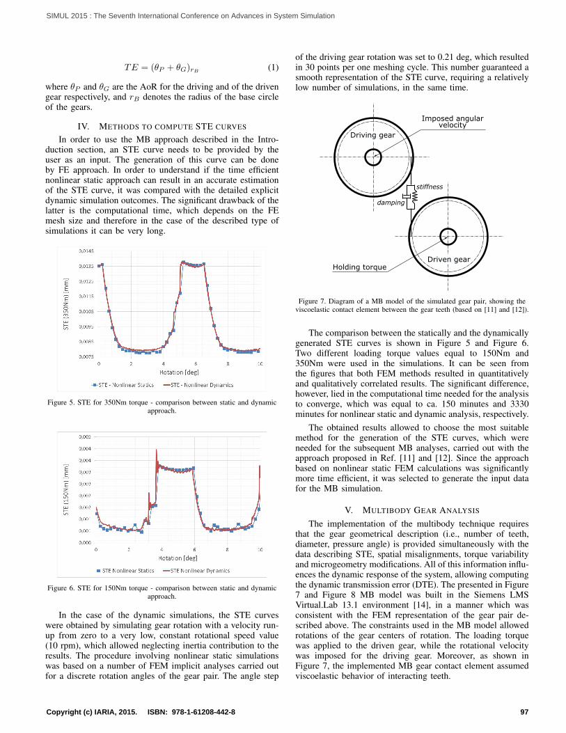
Figure 7. Diagram of a MB model of the simulated gear pair, showing theviscoelastic contact element between the gear teeth (based on [11] and [12]).
The comparison between the statically and the dynamicallygenerated STE curves is shown in Figure 5 and Figure 6.Two different loading torque values equal to 150Nm and350Nm were used in the simulations. It can be seen fromthe figures that both FEM methods resulted in quantitativelyand qualitatively correlated results. The significant difference,however, lied in the computational time needed for the analysisto converge, which was equal to ca. 150 minutes and 3330minutes for nonlinear static and dynamic analysis, respectively.
The obtained results allowed to choose the most suitablemethod for the generation of the STE curves, which wereneeded for the subsequent MB analyses, carried out with theapproach proposed in Ref. [11] and [12]. Since the approachbased on nonlinear static FEM calculations was significantlymore time efficient, it was selected to generate the input datafor the MB simulation.
V. MULTIBODY GEAR ANALYSIS
The implementation of the multibody technique requiresthat the gear geometrical description (i.e., number of teeth,diameter, pressure angle) is provided simultaneously with thedata describing STE, spatial misalignments, torque variabilityand microgeometry modifications. All of this information influ-ences the dynamic response of the system, allowing computingthe dynamic transmission error (DTE). The presented in Figure7 and Figure 8 MB model was built in the Siemens LMSVirtual.Lab 13.1 environment [14], in a manner which wasconsistent with the FEM representation of the gear pair de-scribed above. The constraints used in the MB model allowedrotations of the gear centers of rotation. The loading torquewas applied to the driven gear, while the rotational velocitywas imposed for the driving gear. Moreover, as shown inFigure 7, the implemented MB gear contact element assumedviscoelastic behavior of interacting teeth.
97Copyright (c) IARIA, 2015. ISBN: 978-1-61208-442-8
SIMUL 2015 : The Seventh International Conference on Advances in System Simulation

The DTE curves presented in Figure 9 and Figure 10 wereobtained under rotational speed linear run-up conditions, from0 rpm to 3500 rpm and for two values of the loading torque:150Nm and 350Nm. The simulated operating time was set to70 seconds. Since the two gears had a number of teeth equalto 57, the type of excitation due to meshing stiffness variationalong one meshing cycle could be considered as a multi-harmonic frequency sweep. With the maximum rotationalvelocity, it generated an excitation fundamental frequency of3325 Hz.
Figure 8. Gears model in multibody dynaminics simulation environment.
By looking at the envelopes of the obtained DTE curves,some local amplitude amplifications can be seen. These cor-responded with the gear pair resonance, excited by the TE,due to gear meshing stiffness variability. In the case of thesystem loaded by the 150Nm torque (Figure 9), the mostsignificant DTE amplifications were found at 116Hz, 438Hz,597Hz, 907Hz and 1804Hz, while for the same mechanicaltransmission loaded by the 350Nm torque (Figure 10), theDTE amplifications were found at 122Hz, 479Hz, 650Hz,980Hz and 1958Hz. The differences between these values aresummarized in Table II.
Indeed, in the utilized modeling method, the gear meshingstiffness variation is derived from the STE curve supportedby the user and shows a stiffening behavior which is typicalof contact problems [15]. Based on its periodic, time-varyingcharacteristics it was possible to cover the nonlinearitiespresent in the described system. In the discussed analyses, theSTE curves depicted in Figure 5 and Figure 6 were used.
Figure 9. DTE calculated in run-up conditions, for spur gears pair loaded by150Nm torque.
The obtained results prove the capabilities of the usedthree-dimensional MB modeling methodology, based on theFE gear contact formulation described in Section III. Thedepicted in Figure 9 and Figure 10 gear pair behavior couldnot be captured by consideration of a standard one-dimensionalor planar, linear representation of interacting teeth, describedin the introductory paragraph - Section I. This is because
TABLE II. THE DTE AMPLIFICATIONS IDENTIFIED FOR THE ANALYSEDSPUR GEAR PAIR IN RUN-UP CONDITIONS.
DTE Loading torque Differenceamplification id 150Nm 350Nm ∆ ∆[%]
1 116 122 6 5.172 438 479 41 9.363 597 650 54 9.054 907 980 72 7.945 1804 1958 153 8.48
Figure 10. DTE calculated in run-up conditions, for spur gears pair loadedby 350Nm torque.
these simplified models neglect the contact stiffness variabilityalong the tooth profile. On the other hand, if applied, morecomprehensive FEM analyses could have resulted in the sameresults, as it was shown in Ref. [2]. However, in the presentedcase, the computational time was significantly lower comparedwith a possible dynamic FEM calculations (e.g., shown inSection III), and was equal to ca. 36 minutes on a standarddesktop computer: [email protected] CPU, 32GB RAM.
VI. CONCLUSION AND FUTURE WORK
It was shown in the paper that it is possible to analyze thenonlinear behavior of a meshing gear pair, using a simplified,yet efficient MB analysis technique. By application of thismethod, the time needed for a comprehensive analysis of adriveline system is orders of magnitude lower, when comparedwith the equivalent dynamic FEM calculations. This allowsto support the industrial design process with an accurateand time-efficient simulation tool, which would make feasiblethe assessment of different gear design variants during thevirtual prototyping phase. Moreover, the proposed method-ology for the DTE estimation can be effectively employedfor the purposes of driveline structural optimization, whichrequires a number of iteratively carried out simulations andhence, can be very time consuming. Because of the numericalcomplexity, this would not be possible using the classicalFEM-based approach. The activity scheduled as the nearestfuture step of the research work presented in this paper isaimed at improving gearbox noise and vibration characteristics,by application of teeth profile microgeometry modifications.By implementation of the described methodology and becauseof its time-efficiency, the optimization approach can be morecomprehensive, including different load cases and operationalconditions. This will ease convergence to a global optimum ofthe imposed problem.
ACKNOWLEDGMENT
The research activities described in this paper were fundedwithin the People Programme (Marie Curie Actions) of the
98Copyright (c) IARIA, 2015. ISBN: 978-1-61208-442-8
SIMUL 2015 : The Seventh International Conference on Advances in System Simulation
7th Framework Programme of the European Union FP7/2007-2013, under the contract with the Research Executive Agency(REA) n. 324336 and the related research project DEMETRADesign of Mechanical Transmissions: Efficiency, Noise andDurability Optimization (www.fp7demetra.eu).
REFERENCES[1] S. Shweiki, A. Palermo, A. Toso, D. Mundo, and W. Desmet, “Effects
of center distance and microgeometry on the dynamic behaviour ofa spur gear pair,” in Proceedings of the International Conference onEngineering Vibration (ICOEV 2015) September 7–10, 2015, Ljubljana,Slovenia, 2015, pp. 119–130.
[2] F. L. Litvin and F. A., Eds., Gear geometry and applied theory.Cambridge University Press, 2004, ISBN: 0-521-81517-7.
[3] H. N. Ozguven and D. R. Houser, “Dynamic analysis of high speedgears by using loaded static transmission error,” Journal of Sound andVibration, vol. 125.1, 1988, pp. 71–83, ISSN: 0022-460X.
[4] G. Liu and R. G. Parker, “Dynamic modeling and analysis of tooth pro-file modification for multimesh gear vibration,” Journal of MechanicalDesign, vol. 130, no. 12, 2008, p. 121402.
[5] D. R. Houser, J. Harianto, and Y. Ueda, “Determining the source ofgear whine noise,” Gear Solutions, vol. 1623, 2004, pp. 17 – 22.
[6] J. D. Smith, Gear noise and vibration. CRC Press, 2003.[7] S. Theodossiades and S. Natsiavas, “Non-linear dynamics of gear-pair
systems with periodic stiffness and backlash,” Journal of Sound andvibration, vol. 229, no. 2, 2000, pp. 287–310.
[8] Q. Ma and A. Kahraman, “Period-one motions of a mechanical os-cillator with periodically time-varying, piecewise-nonlinear stiffness,”Journal of Sound and Vibration, vol. 284, 2005, pp. 893–914.
[9] R. G. Parker, S. M. Vijayakar, and T. Imajo, “Non-linear dynamicresponse of a spur gear pair: modelling and experimental comparisons,”Journal of sound and vibration, vol. 237, no. 3, 2000, pp. 435–455.
[10] V. K. Tamminana, A. Kahraman, and S. Vijayakar, “A study of therelationship between the dynamic factors and the dynamic transmissionerror of spur gear pairs,” Journal of Mechanical Design, vol. 129, 2007,pp. 75–84.
[11] A. Palermo, D. Mundo, R. Hadjit, and W. Desmet, “Multibody elementfor spur and helical gear meshing based on detailed three-dimensionalcontact calculations,” Mechanism and Machine Theory, vol. 62, 2013,pp. 13–30.
[12] A. Palermo, D. Mundo, R. Hadjit, and Desmet, “Effects of variableloads and misalignments on gear noise and vibration through multibodysimulation based on transmission error,” in Proceedings of the Inter-national Conference on Noise and Vibration Engineering (ISMA2012)and 4th International Conference on Uncertainty in Structural Dynamics(USD2012) September 17–19, 2012, Leuven, Belgium, 2012, pp. 3995–4006.
[13] R. Version, “5.1, radioss theory manual, altair engineering,” Inc., Troy,MI, 2008.
[14] Siemens PLM Software, LMS Virtual.Lab 13.2,http://www.siemens.com/plm/lms, 2015.
[15] K. L. Johnson and K. L. Johnson, Contact mechanics. Cambridgeuniversity press, 1987.
99Copyright (c) IARIA, 2015. ISBN: 978-1-61208-442-8
SIMUL 2015 : The Seventh International Conference on Advances in System Simulation