combining software methods fo r effective deployment of...
TRANSCRIPT

IJCSNS International Journal of Computer Science and Network Security, VOL.10 No.12, December 2010
134
Manuscript received December 5, 2010. Manuscript revised December 20, 2010.
Combining Software Methods for Effective Deployment of Programmable Logic Controllers (PLCs)
Lucien Ngalamou† and Leary Myers††
†School of Engineering, Grand Valley State University, 301 W. Fulton, Grand Rapids, MI 49504 ††University of the West Indies, Mona Campus, Kingston 7, Jamaica
Summary This paper presents a preliminary study of an approach that models programmable logic controllers (PLCs) for their effective deployment in industrial control processes. A working model is developed for automatic allocation of PLCs and also a formal verification of Ladder Diagram representations of control processes using the Symbolic Model Verifier (SMV) tool. Automatic resource allocation is achieved through the proposition of a digraph model for any Ladder Diagram representation of a control process, which is then translated to an XML (Extensible Mark Up Language) model. The required PLC resources needed to implement a control process are extracted from the XML model. These resources are then used by a selection engine to determine, from a PLC database, the most appropriate PLCs or Embedded Controllers (EBCs) that can satisfy the resource requirements. Additionally, information extracted from the XML model is used to generate a formally verifiable SMV code of the system. This paper focuses on the practical implementation, testing, and verification of three conceptual modules applied to a control process. These are, the XML model of the control process, the PLC Database Automatic Resource Allocation, and the XML-to-SMV translator. This work was significantly motivated by the ever increasing number of industries who seek to increase their productivity by automating their processes. Key words: Automatic Resource Allocation, XML Model, Programmable Logic Controllers (PLCs), PLC Database, XML to SMV Translation, and Formal Verification.
1. Introduction
In a broad sense, a programmable logic controller (PLC) can be defined as a microcomputer as well as a microcontroller [22, 28]. They both comprise the same basic components: an arithmetic and logic unit (ALU), a control section, a local memory area, and the input/output (I/O) ports. However, they are usually less powerful than a personal computer. Some common PLC applications are:
- batch processing and material handling in the chemical industry,
- machining and test stand control, - wood and chip handling in the lumber industry, - filling and packaging in the food industry, and
- furnace and rolling mill controls in the metal industry [28].
PLCs are now used to replace traditional relay-based controllers that were used to control industrial processes as PLCs offer more flexible options. The menu of options that contribute to this flexibility include:
- the small size of the PLC which facilitates locality of the controller with the machine or the process being controlled,
- user friendly computer software to allow specification of the control process in the standard methods of programming (ICE, 1993) whether Structured Text (ST), Function Block Diagram (FBD), Instruction List (IL), Sequential Function Chart (SFC), Ladder Diagram (LD) or other modern programming constructs such as state diagrams,
- networking in local area networks (LAN) which allows for remote management of control processes through communication ports and the standardization of hardware interfaces for manufacturer interchangeability [12, 28, 29].
In exploring the most efficient method for the effective deployment of resources, ladder logic diagrams (LD) is chosen. According to Van Elk et. al [28], LD is a graphical language based on ladder programming. LD is a technique that evolved from the electrical wiring diagrams that were used in the car industry for describing relay control schemes and is now widely used to program the current generation of PLCs. LDs can be used to formally represent any relay based binary control and offers a smooth transition for electrical engineers, who previously worked with relay ladder logic (RLL) and electrical wiring diagrams. In the PLC industry, it is generally an accepted fact that the task of selecting the correct PLC for a particular system is a very difficult one [3]. It is for this reason that the automation of processes is of such importance. In choosing a PLC, some of the many parameters that have to be considered are: the number of inputs and outputs, the program memory, data memory size, the number of communication ports, the number of

IJCSNS International Journal of Computer Science and Network Security, VOL.10 No.12, December 2010
135
instructions that they support [3]. These parameters are organized as part of a database. The database attempts to capture most if not all of these variables, thereby allowing a selection engine to execute the most detailed search possible. Code estimation is used to calculate the values for specific database component attributes, that can be gleaned from the ladder logic program leading to the selection of the appropriate component. Writing correct Ladder Diagram programs is often considered to be a difficult task as stated in [26]. The requirements that have to be considered include: the algorithm to be used, translating the algorithm to appropriate ladder diagram instructions, writing the program, testing, debugging the program and the production of adequate documentation. Formal verification tools can be used to improve and ensure the accuracy of this process while designing a system. The Cadence Formal Check verification tool [8], that is based on the SMV formal language, was used in this study. The XML model representation of the PLC program was converted to the SMV input language. The SMV input language can be used to describe synchronous or asynchronous finite state systems. The overview of the concept of resource allocation and formal verification as part of a ladder diagram integrated tool [18] is shown in figure 1.
Fig. 1. Architecture Overview of the Multi-target Tool ( LLD: ladder logic diagram; ARA: automatic resource allocation; RCG: retargetable
code generation)
The research work presented in this paper consists of three major parts: the creation of a PLC database, the automatic resource allocation engine, the XML to SMV model generation and the verification. Section 2 gives an overview of the PLC Database development, followed by
section 3, which presents the PLC selection engine. The aspect of the study that deals with the XML to SMV model generation for formal verification of the PLC program is presented in section 4. Section 5 presents a case study and its results. Section 6 provides a conclusion and future direction.
2. PLC Database Development
The process to be controlled is firstly represented through a LD, and then modeled as an XML document model. From the analysis of the XML document, it is possible to determine the number of operations or instructions that are needed to execute the program. This also enables the determination of the size of the memory that will be required to retain the program, the number of inputs/outputs and the approximate program execution time. The necessary information from the analysis of data sheets is captured and represented in the database. This information represents essential parameters for PLCs and embedded controllers. These variables provide a base from which it is possible to make a selection of the most suitable PLC for the intended configuration. Alternatively a user may desire to search the database for embedded controllers that satisfy his specification such as the size of the address or data bus, the clock speed, the size of the memory, the number of input/output ports, and execution speed. The database [5] has the ability to generate reports, thereby providing further detailed information on the design of the particular PLC or embedded controller. Entities, relationships and accompanying attributes that are required for the creation of the database were derived from the analysis of the data sheets for the PLCs and microcontrollers. The detailed arrangement of the specifications on the data sheets offered a very detailed source of information especially for attributes. Tables are analyzed and arranged in a manner that would most suitably represent the data in the database. Tables are not only created to represent the characteristics or properties of PLCs and embedded controllers but also for the support software and accessories that may be required in constructing a system. Every effort was made to reduce redundancy and conserve on physical storage while improving performance by presenting a reasonably normalized database. A conceptual view of the database can be seen in Figure 2 below. PLCSCHEMA is the only schema that owns tables. For each of these tables a public synonym of the same name is created. The PLC_USER_ROLE role object is created to be used to administer a set of privileges on the tables owned by PLCSCHEMA. The object privileges SELECT, INSERT and UPDATE, along with the CONNECT privilege are granted to the

IJCSNS International Journal of Computer Science and Network Security, VOL.10 No.12, December 2010
136
PLC_USER_ROLE object. This role is then granted to the PLC USER1 database user object, which essentially give it access to the tables of the PLCSCHEMA through the existing synonyms. Hence security is managed through the PLC_USER_ROLE and users that are granted this role will not be able to alter or delete data from the tables.
Fig. 2. The Conceptual View of the Database [9].
3. Resource Allocation Method
Many parameters have to be taken into consideration. The most important ones are: the number of inputs/outputs, the program memory and data memory sizes, the number of communication ports, and the number of instructions [19]. The database presented in section 2 of this paper attempts to capture most if not all of these variables through a selection engine that allows for one of the most detailed searches possible. Code estimation is used to estimate the values for specific database component attributes that can be gleaned from the ladder logic program thereby facilitating the selection of the appropriate component. The approach taken is to first determine a suitable representation for the process.
A digraph is used to represent the process as it can be easily used to represent the flow of execution of a ladder logic program. Extensible Markup Language (XML ) [30], because of its portability and inter-operability, is used to represent our ladder logic programs. The selection engine is able to parse the XML model and determine the values
of the various parameters that are represented. The output parameters of the parsing process are used to determine the optimal set of PLCs that can suitably implement the system.
A listing of the parameters and the values that were obtained from the XML model and used in the query to the database can be viewed from the menu. This sequencing supports the automatic selection process. Further detailed reports can be generated as needed for PLC or EBC in the result set. Reports can be generated to list the PLCs, EBCs or the respective modules in the database. The conceptual model is shown in Figure 3.
Fig. 3. Model for code estimation and component selection.
3.1. Implementing the Selection Engine
This search engine is implemented using the Java programming language which is known for its portability. It uses the Simple API for XML [24] to implement a parser that parses the XML document representing a ladder diagram program of a control process. As documented in [9], a ladder diagram can be expressed as a
IJCSNS International Journal of Computer Science and Network Security, VOL.10 No.12, December 2010
137
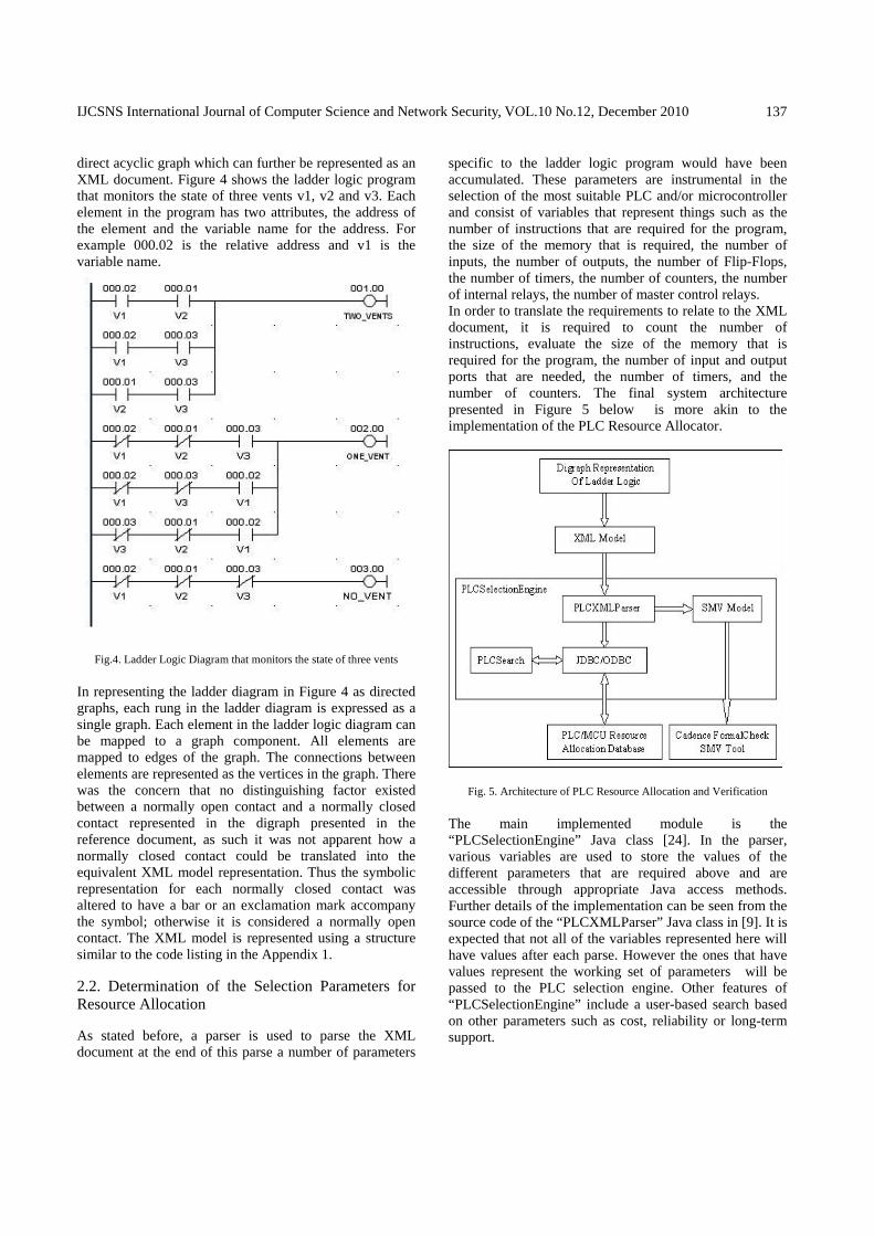
direct acyclic graph which can further be represented as an XML document. Figure 4 shows the ladder logic program that monitors the state of three vents v1, v2 and v3. Each element in the program has two attributes, the address of the element and the variable name for the address. For example 000.02 is the relative address and v1 is the variable name.
Fig.4. Ladder Logic Diagram that monitors the state of three vents
In representing the ladder diagram in Figure 4 as directed graphs, each rung in the ladder diagram is expressed as a single graph. Each element in the ladder logic diagram can be mapped to a graph component. All elements are mapped to edges of the graph. The connections between elements are represented as the vertices in the graph. There was the concern that no distinguishing factor existed between a normally open contact and a normally closed contact represented in the digraph presented in the reference document, as such it was not apparent how a normally closed contact could be translated into the equivalent XML model representation. Thus the symbolic representation for each normally closed contact was altered to have a bar or an exclamation mark accompany the symbol; otherwise it is considered a normally open contact. The XML model is represented using a structure similar to the code listing in the Appendix 1.
2.2. Determination of the Selection Parameters for Resource Allocation
As stated before, a parser is used to parse the XML document at the end of this parse a number of parameters
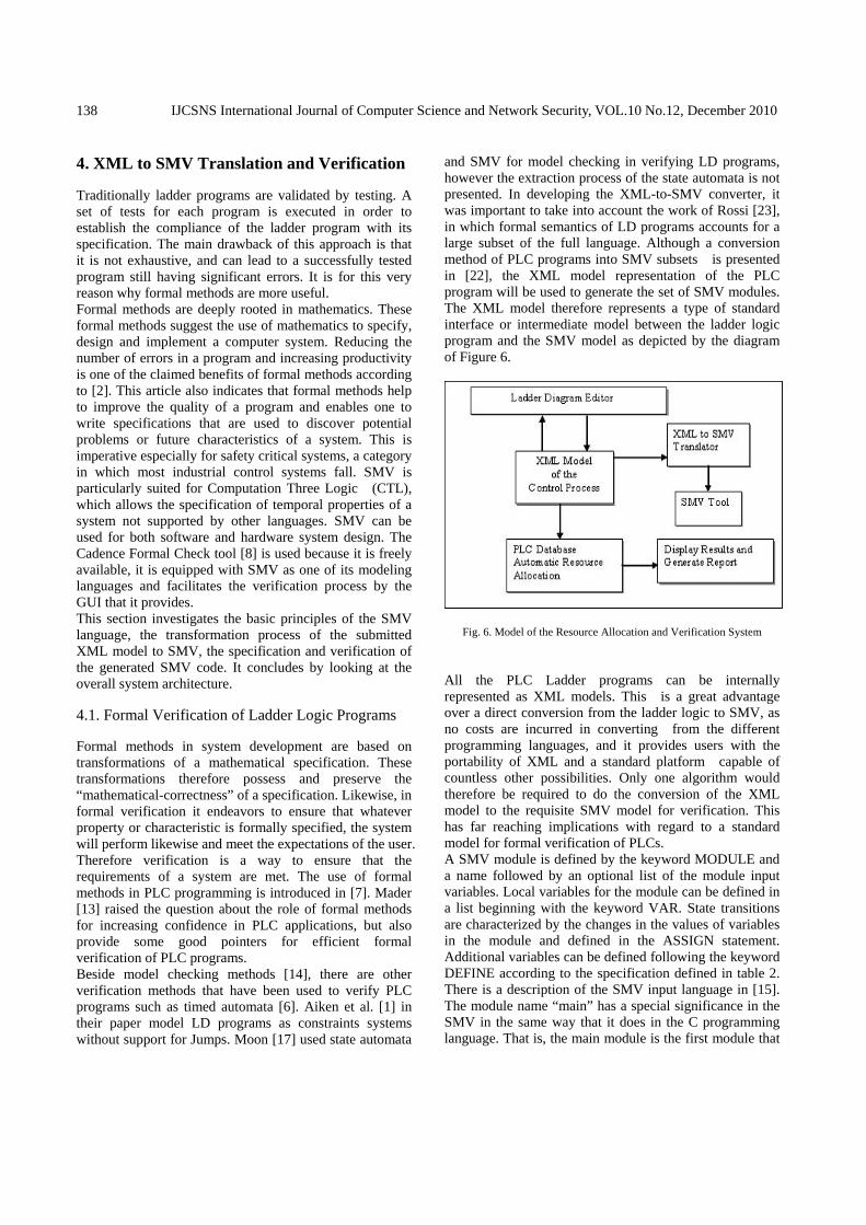
specific to the ladder logic program would have been accumulated. These parameters are instrumental in the selection of the most suitable PLC and/or microcontroller and consist of variables that represent things such as the number of instructions that are required for the program, the size of the memory that is required, the number of inputs, the number of outputs, the number of Flip-Flops, the number of timers, the number of counters, the number of internal relays, the number of master control relays. In order to translate the requirements to relate to the XML document, it is required to count the number of instructions, evaluate the size of the memory that is required for the program, the number of input and output ports that are needed, the number of timers, and the number of counters. The final system architecture presented in Figure 5 below is more akin to the implementation of the PLC Resource Allocator.
Fig. 5. Architecture of PLC Resource Allocation and Verification
The main implemented module is the “PLCSelectionEngine” Java class [24]. In the parser, various variables are used to store the values of the different parameters that are required above and are accessible through appropriate Java access methods. Further details of the implementation can be seen from the source code of the “PLCXMLParser” Java class in [9]. It is expected that not all of the variables represented here will have values after each parse. However the ones that have values represent the working set of parameters will be passed to the PLC selection engine. Other features of “PLCSelectionEngine” include a user-based search based on other parameters such as cost, reliability or long-term support.
IJCSNS International Journal of Computer Science and Network Security, VOL.10 No.12, December 2010
138
4. XML to SMV Translation and Verification
Traditionally ladder programs are validated by testing. A set of tests for each program is executed in order to establish the compliance of the ladder program with its specification. The main drawback of this approach is that it is not exhaustive, and can lead to a successfully tested program still having significant errors. It is for this very reason why formal methods are more useful. Formal methods are deeply rooted in mathematics. These formal methods suggest the use of mathematics to specify, design and implement a computer system. Reducing the number of errors in a program and increasing productivity is one of the claimed benefits of formal methods according to [2]. This article also indicates that formal methods help to improve the quality of a program and enables one to write specifications that are used to discover potential problems or future characteristics of a system. This is imperative especially for safety critical systems, a category in which most industrial control systems fall. SMV is particularly suited for Computation Three Logic (CTL), which allows the specification of temporal properties of a system not supported by other languages. SMV can be used for both software and hardware system design. The Cadence Formal Check tool [8] is used because it is freely available, it is equipped with SMV as one of its modeling languages and facilitates the verification process by the GUI that it provides. This section investigates the basic principles of the SMV language, the transformation process of the submitted XML model to SMV, the specification and verification of the generated SMV code. It concludes by looking at the overall system architecture.
4.1. Formal Verification of Ladder Logic Programs
Formal methods in system development are based on transformations of a mathematical specification. These transformations therefore possess and preserve the “mathematical-correctness” of a specification. Likewise, in formal verification it endeavors to ensure that whatever property or characteristic is formally specified, the system will perform likewise and meet the expectations of the user. Therefore verification is a way to ensure that the requirements of a system are met. The use of formal methods in PLC programming is introduced in [7]. Mader [13] raised the question about the role of formal methods for increasing confidence in PLC applications, but also provide some good pointers for efficient formal verification of PLC programs. Beside model checking methods [14], there are other verification methods that have been used to verify PLC programs such as timed automata [6]. Aiken et al. [1] in their paper model LD programs as constraints systems without support for Jumps. Moon [17] used state automata
and SMV for model checking in verifying LD programs, however the extraction process of the state automata is not presented. In developing the XML-to-SMV converter, it was important to take into account the work of Rossi [23], in which formal semantics of LD programs accounts for a large subset of the full language. Although a conversion method of PLC programs into SMV subsets is presented in [22], the XML model representation of the PLC program will be used to generate the set of SMV modules. The XML model therefore represents a type of standard interface or intermediate model between the ladder logic program and the SMV model as depicted by the diagram of Figure 6.
Fig. 6. Model of the Resource Allocation and Verification System
All the PLC Ladder programs can be internally represented as XML models. This is a great advantage over a direct conversion from the ladder logic to SMV, as no costs are incurred in converting from the different programming languages, and it provides users with the portability of XML and a standard platform capable of countless other possibilities. Only one algorithm would therefore be required to do the conversion of the XML model to the requisite SMV model for verification. This has far reaching implications with regard to a standard model for formal verification of PLCs. A SMV module is defined by the keyword MODULE and a name followed by an optional list of the module input variables. Local variables for the module can be defined in a list beginning with the keyword VAR. State transitions are characterized by the changes in the values of variables in the module and defined in the ASSIGN statement. Additional variables can be defined following the keyword DEFINE according to the specification defined in table 2. There is a description of the SMV input language in [15]. The module name “main” has a special significance in the SMV in the same way that it does in the C programming language. That is, the main module is the first module that

IJCSNS International Journal of Computer Science and Network Security, VOL.10 No.12, December 2010
139
will be executed. Execution of assignment statements in an SMV program are done simultaneously and in parallel. 4.2. Transformation of the XML Model to SMV In constructing the SMV model, the focus is on the flow of execution of the ladder logic program. That is the left to right execution of each rung from the top to the bottom of the program will be modeled. As Figure 7 shows each transition, except for the first, models a sequential evaluation.
Fig. 7. Ladder Logic program transition diagram
The jump instruction was not considered in this study. These transitions will be modeled in SMV through the next function placed in the ASSIGN section of the main module. However a modular approach is employed which ensures the sequential execution of each rung. The implementation is based on the concept of the Simplified Incidence Matrix Java Vectors. Vectors are used to store the matrix incident edges and vertices separately although there is a direct correlation of the indexes. For the “Up” and “Down” edges of the ladder diagram vectors are also used to store the “From” vertices and the “To” vertices as necessary. In the “Up” edges structure, the “To” vertices actually represent all the vertices where branching occurs in the ladder diagram. There are other methods of representing the SMV model for example representing each contact as an individual module with its own state and transition, declaring instances of these contact modules and composing these modules through a rung module. Other existing rungs would likewise be composed in a similar fashion. Instances of these rung modules would subsequently be wrapped in a main module for a total representation of the ladder program. However, although such an approach would be considered modular it is also an unnecessarily bulky approach. It may have cost effects on time and the execution resources used as indicated in [22].
4.3. SMV Specification and Verification
Verification is performed by defining the main module which will consist of the specification(s) written in Computation Tree Logic (CTL) or temporal logic to be verified. The result of SMV verification is a message stating whether the CTL specification is true or false. If it is not true, a counter example is generated indicating a
sequence of state transitions that leads to a violation of the CTL specification (see example in [16]). The CTL is a reachability tree for the finite state machine defined by the SMV model. CTL statements consist of a temporal logic operator along with a logical expression. The temporal logic operators are E, A, X, F, G and U where:
• E represents the existential path quantifier • A represents the universal path quantifier • X represents the next time • F represents the future • G represents globally • U represents until
Therefore with an expression q, a CTL formula or specification could be written as Fq meaning that q holds some time in the future, Xq meaning that q holds for the next state and so on. If there is more than one SPEC declaration the specification is the conjunction of all the SPEC declarations. Each of the formulas would be evaluated and the results reported separately in the order of the SPEC declaration in the program text. Considering the example of section 3, a specification can be written that ensures that each rung will be able to “open” or “close” the particular vent being monitored. Hence the derived SMV main module representation of the PLC program would be: MODULEmain V AR
in1 : boolean; in2 : boolean; in3 : boolean; r1 : rung1(in1; in2; in3); r2 : rung2(r1:c1; r1:c2; r1:c3); r3 : rung3(r2:c1; r2:c2; r2:c3);
SPEC AG(EF(r1:output)&EF!r1:output& EF(r2:output)&EF!r2:output& EF(r3:output)&EF!r3:output)
Variables in1, in2, and in3 are declared to be of type Boolean in this program but are not assigned values. This leaves the SMV system free values for this these variables, giving them the characteristics of being unconstrained inputs to the system. Instances r1, r2 and r3 represent rung 1, rung 2 and rung 3 respectively which monitors the three different vents. Inputs to rung2 are driven by the inputs to the instance of rung 1. Likewise inputs to rung3 are driven by the inputs to the instance of rung 2. The specification that we are verifying states that the behavior of the system is to allow the vents to be turned “on” and “off”. The result of this SMV verification was true and was done with the Cadence FormalCheck SMV tool [8]. The resources used for this model are minimal: user time - 0.015625 s, system time - 0.03125 s, BDD [33] nodes allocated - 94, and data segment size - 0. As presented in [16], it is important to note that model checking only checks the model of the system. For

IJCSNS International Journal of Computer Science and Network Security, VOL.10 No.12, December 2010
140
example, when SMV declares a claim as ’true’ or ’false’, this is with respect to the system model whether or not it accurately represents the system.
4.4. System Architecture
The major components of a system and the communication Between these components identify its structural framework or its architectural design. The final system architecture is presented in Figure 5. The main implemented module is the “PLCSelectionEngine” and it contains other sub-modules. The actualization of the “PLCSelectionEngine”, formal verification of a ladder diagram, and the PLC database actualization were presented previously. The java code for the full implementation of the “PLCSelectionEngine” and the generation of the SMV given [9]. The next section presents a study of a test case used with the Resource Allocator and the results obtained.
5. Case Study
The aim of this case study is to demonstrate, that given an XML model of a control process, the Resource Allocator tool can be used to select the appropriate PLCs or EBCs. The user is then able to generate a report for each PLC returned in the results of the query to the database. This may include additional modules, supporting materials, accessories, and diagrams from the database that are linked to the particular PLC or microcontroller. Likewise report listings of the contents of the database can be generated on demand. Figure 8 shows the snapshot of the prototype execution.
Fig. 8. Resource Allocator Prototype Execution
After submitting the XML file (i.e: VentSystemLadderDiagram.xml [9]), the Resource Allocator automatically generates, the list of PLCs/EBCs in a database that matches the generated parameters. In order to view the parameters that were used to generate the results, we use the View menu option and select the “Generated Parameters” sub-menu item as shown in Figure 9.
Fig. 9. Parameters generated from XML file
Likewise, to see the verifiable generated SMV code, the user should go to the View sub-menu and select the SMV Code menu item (Figure 10).
Fig. 10. SMV code generated from XML file

IJCSNS International Journal of Computer Science and Network Security, VOL.10 No.12, December 2010
141
We will present only one case study. The remaining examples are described in [9].
Consider the example of a real-life control process, that consists of a painting system (Figure 11).
Fig. 11. Diagram of the painting system [11]
A conveyor system that retrieves parts as is needed for a robot to complete paint job. The robot sweeps over the part, before the part can move on. The sensor lamps must be on for the conveyor to work. All actuators and lamps should be off when the switch is off. When the “On” switch is turned, the conveyor should start. It should run until PE1 indicates the presence of a part at the paint station. At this point, the conveyor should automatically turn off. The paint arm, which is assumed to have started in its counter clockwise position, should be moved to the clockwise position (CW), and then back to counter clockwise (CCW) position. While the paint arm is moving, the paint should be spraying (represented by the Red lamp being on). After a complete spray operation, the Red lamp should be off. The green light should turn on and stay on for two seconds (use of a timer), indicating the process is complete. The conveyor should then turn on again. The system should then receive another part. Figure 12 gives a snapshot of the ladder diagram of a painting system. The system controller has a set of inputs and outputs (tables 2 and 3).
Table 1. Inputs required by painting controller Inputs Description
PE1 Photo Electric sensor signal that indicates the position of the part
being painted (begin)
PE2 Photo Electric sensor signal that indicates the position of the part
being painted (end)
CCWSense Sensing position signal of the paint
arm and its rotation counter clockwise
CWSense Sensing position signal of the paint
arm and its rotation counter clockwise
OnSwitch Signal that starts the processStopSwitch Signal that stops the process
G_timer Signal that activates the 2-second timer
Table 2. Outputs of the painting controller Outputs Description
CCWMotor Control Signal used for switching on/off the motor that turns the paint arm counter clockwise
CWMotor Control Signal used for switching on/off the motor that turns the paint arm counter clockwise
ConMotor Control signal used for starting and stopping the conveyor
GLamp Green lamp signalRLamp Red lamp signalSpainter Spray painter control signal
The representative XML representation is saved as a file named PaintingSystemLadderDiagram.xml [9].
Fig. 12. Snap shot of the ladder diagram editor.
Using this file as input to the PLC/EBC Resource Allocator the following results were observed for the generated parameters, the selected PLCs/EBCs, the generated SMV model and verification. The generated parameters are given below: Total Contacts : 25 Number of Branches : 1 Total Instructions : 20 Program Memory Size : 360 words Data Memory Size : 104 words Number of Inputs : 17 Number of Outputs : 8 Number of Timers : 1 The Allocator generates results that are similar to those of the vent control of figure 9. However it is important to recognize that the results returned are dependent on more than one factor. The collective points in the previous case are reiterated here; That is, the type and number of PLCs/MCUs returned depend on the population of the database [9]. Factors such as the variation in the values of the parameters in the database, a larger quantity of data and marked differences in the complexity of the control processes being studied cause greater variation in the results obtained. For example the ”Find dialog” command
IJCSNS International Journal of Computer Science and Network Security, VOL.10 No.12, December 2010
142
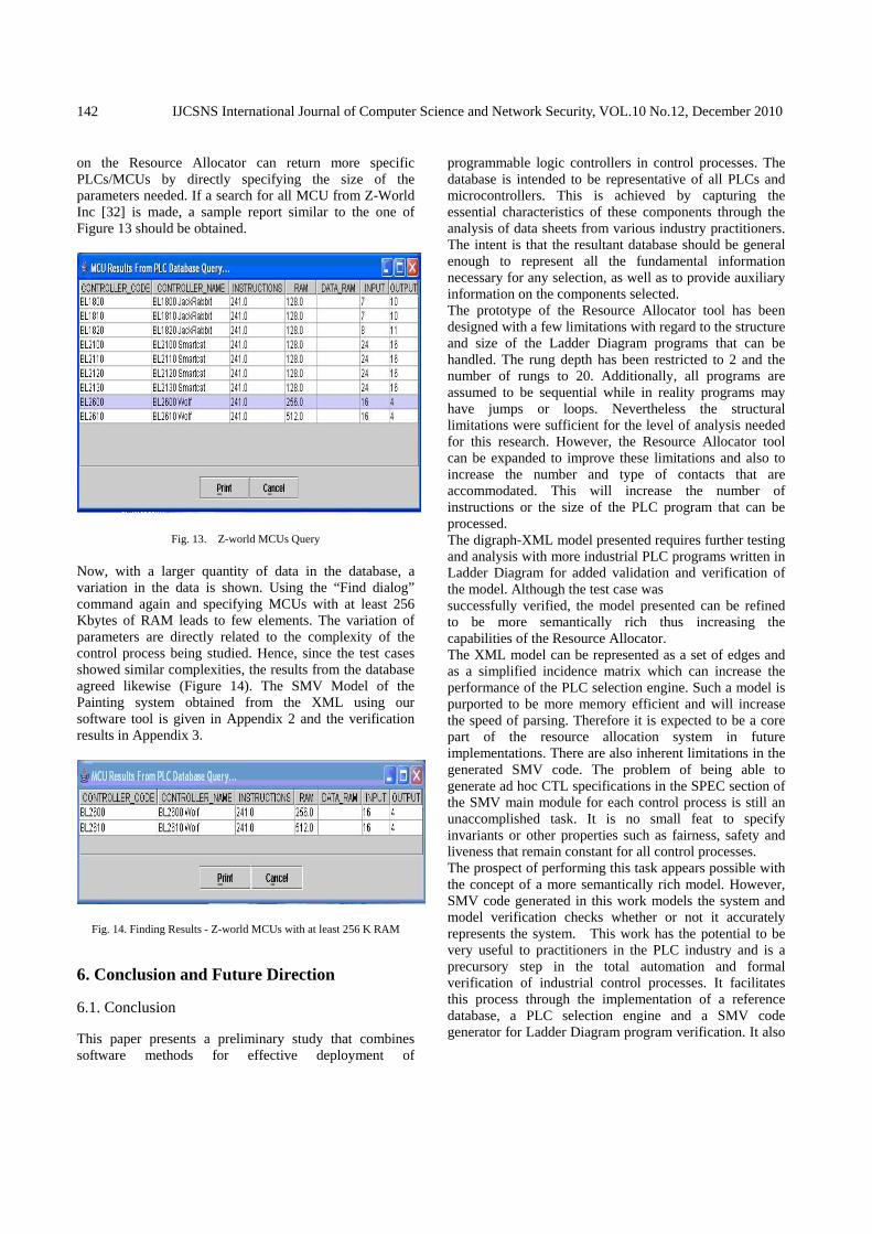
on the Resource Allocator can return more specific PLCs/MCUs by directly specifying the size of the parameters needed. If a search for all MCU from Z-World Inc [32] is made, a sample report similar to the one of Figure 13 should be obtained.
Fig. 13. Z-world MCUs Query
Now, with a larger quantity of data in the database, a variation in the data is shown. Using the “Find dialog” command again and specifying MCUs with at least 256 Kbytes of RAM leads to few elements. The variation of parameters are directly related to the complexity of the control process being studied. Hence, since the test cases showed similar complexities, the results from the database agreed likewise (Figure 14). The SMV Model of the Painting system obtained from the XML using our software tool is given in Appendix 2 and the verification results in Appendix 3.
Fig. 14. Finding Results - Z-world MCUs with at least 256 K RAM
6. Conclusion and Future Direction
6.1. Conclusion
This paper presents a preliminary study that combines software methods for effective deployment of
programmable logic controllers in control processes. The database is intended to be representative of all PLCs and microcontrollers. This is achieved by capturing the essential characteristics of these components through the analysis of data sheets from various industry practitioners. The intent is that the resultant database should be general enough to represent all the fundamental information necessary for any selection, as well as to provide auxiliary information on the components selected. The prototype of the Resource Allocator tool has been designed with a few limitations with regard to the structure and size of the Ladder Diagram programs that can be handled. The rung depth has been restricted to 2 and the number of rungs to 20. Additionally, all programs are assumed to be sequential while in reality programs may have jumps or loops. Nevertheless the structural limitations were sufficient for the level of analysis needed for this research. However, the Resource Allocator tool can be expanded to improve these limitations and also to increase the number and type of contacts that are accommodated. This will increase the number of instructions or the size of the PLC program that can be processed. The digraph-XML model presented requires further testing and analysis with more industrial PLC programs written in Ladder Diagram for added validation and verification of the model. Although the test case was successfully verified, the model presented can be refined to be more semantically rich thus increasing the capabilities of the Resource Allocator. The XML model can be represented as a set of edges and as a simplified incidence matrix which can increase the performance of the PLC selection engine. Such a model is purported to be more memory efficient and will increase the speed of parsing. Therefore it is expected to be a core part of the resource allocation system in future implementations. There are also inherent limitations in the generated SMV code. The problem of being able to generate ad hoc CTL specifications in the SPEC section of the SMV main module for each control process is still an unaccomplished task. It is no small feat to specify invariants or other properties such as fairness, safety and liveness that remain constant for all control processes. The prospect of performing this task appears possible with the concept of a more semantically rich model. However, SMV code generated in this work models the system and model verification checks whether or not it accurately represents the system. This work has the potential to be very useful to practitioners in the PLC industry and is a precursory step in the total automation and formal verification of industrial control processes. It facilitates this process through the implementation of a reference database, a PLC selection engine and a SMV code generator for Ladder Diagram program verification. It also

IJCSNS International Journal of Computer Science and Network Security, VOL.10 No.12, December 2010
143
provides a number of perspectives for future research in the field.
6.2. Future Direction
Further The future direction of this work can be gleaned from the answer to the following question: What is expected in the future of resource allocation and model verification? It is anticipated that more efficient methods for automatic selection and verification will be produced based on enhanced or novel models. This should result in the improved performance of the selection engine. It can be noted that even the simple creation of strategic indexes (indices) in the PLC database can significantly improve the database’s performance as the size of the database is continually increased. However, the focus was on the implementation and functionality of the model, so no indices were created on the reference database. It should be the case that verification is done automatically before the selection engine is called to perform automatic resource allocation. That is, getting a result from the Resource Allocator tool should be dependent on the ladder logic being correct to the users’ specification. Hence we forecast a tighter integration or a convergence of the Resource Allocator and the formal verification tools to produce more complete automation process. This remains a task for a later version of the system. It has been the nature of formal verification to create an intermediate model of the system prior to translating it into the formal language. For example, [10] used state chart, Thomas and Bryla [27] used transition systems diagrams and for our study digraphs and XML. To use our model as the basis for formal verification would require an equivalent digraph representation for the ladder logic programs written in any of the five different PLC programming languages. Essentially, this would allow programs written in other languages to be represented in ladder diagram according to our specifications. A tool that represents ladder diagrams internally as digraphs and that generates the corresponding XML model from the ladder diagram programs is created in [4, 18] The generated XML model is then used to generate the formal model in SMV for verification. Alternatively, a common XML model could be found for the programming languages represented in the International Electro-technical Commission (IEC) standard, IEC 61131- 3, which can be used for the basis of all PLC verification. Achieving any of these could be the precursor for the standardization of formal verification of ladder diagrams using SMV.
Appendixes Appendix 1: Sample XML Model </LadderDiagram> ... - <Graph graphNumber=”3”> - <Vertices> - <Vertex number=”0”> <startX>60.0</startX> <startY>470.0</startY> </Vertex> - <Vertex number=”24”> <startX>180.0</startX> <startY>470.0</startY> </Vertex> = <Vertex number=”25”> <startX>300.0</startX> <startY>470.0</startY> </Vertex> - <Vertex number=”26”> <startX>420.0</startX> <startY>470.0</startY> </Vertex> -<Vertex number=”27”> <startX>540.0</startX> <startY>470.0</startY> </Vertex> </Vertices> - <Edges> -<Edge type=”CloseContactEdge”> <from>0</from> <to>24</to> <address>000.02</address> <symbol>V1</symbol> </Edge> - <Edge type=”CloseContactEdge”> Exploring an Approach for Effective Deployment of Programmable Logic Controllers (PLCs) 11 <from>24</from> <to>25</to> <address>000.01</address> <symbol>V2</symbol> </Edge> - <Edge type=”CloseContactEdge”> <from>25</from> <to>26</to> <address>000.03</address> <symbol>V3</symbol> </Edge> - <Edge type=”OpenOutputEdge”> <from>26</from> <to>27</to> <address>003.00</address> <symbol>NO VENT</symbol> </Edge>

IJCSNS International Journal of Computer Science and Network Security, VOL.10 No.12, December 2010
144
</Edges> </Graph> </LadderDiagram> Appendix 2: Generated SMV from the XML model of the Painting System Controller MODULE rung1(ONSWITCH,OFFSWITCH,START) VAR
output : boolean; ASSIGN
init(output) := 0; next(output) := (ONSWITCH — START) & (!OFFSWITCH);
DEFINE c1 := ONSWITCH; c2 := OFFSWITCH; c3 := START;
MODULE rung2(ONSWITCH,PE1,START) VAR
output : boolean; ASSIGN
init(output) := 0; next(output) := (ONSWITCH & !PE1 & !START);
DEFINE c1 := ONSWITCH; c2 := PE1; c3 := START;
MODULE rung3(PE1,CCWSENSE) VAR
output : boolean; ASSIGN
init(output) := 0; next(output) := (PE1 & !CCWSENSE);
DEFINE c1 := PE1; c2 := CCWSENSE;
MODULE rung4(PE1,CCWSENSE) VAR
output : boolean; ASSIGN
init(output) := 0; next(output) := (PE1 & !CCWSENSE);
DEFINE c1 := PE1; c2 := CCWSENSE;
MODULE rung5(PE1,CCWSENSE) VAR
output : boolean; ASSIGN
init(output) := 0; next(output) := (PE1 & !CCWSENSE);
DEFINE c1 := PE1; c2 := CCWSENSE;
MODULE rung6(CCWSENSE,CWSENSE) VAR
output : boolean;
ASSIGN init(output) := 0; next(output) := (!CCWSENSE & CWSENSE);
DEFINE c1 := CCWSENSE; c2 := CWSENSE;
MODULE rung7(CCWSENSE,GTIMER) VAR
output : boolean; ASSIGN
init(output) := 0; next(output) := (CCWSENSE & !GTIMER);
DEFINE c1 := CCWSENSE; c2 := GTIMER;
MODULE rung8(GLAMP) VAR
output : boolean; ASSIGN
init(output) := 0; next(output) := (GLAMP);
DEFINE c1 := GLAMP;
MODULE main VAR
in1 : boolean; in2 : boolean; in3 : boolean; in4 : boolean; in5 : boolean; in6 : boolean; r1 : rung1(in1,in2,r1.output); r2 : rung2(r1.c1,in3,r1.c3); r3 : rung3(r2.c2,in4); r4 : rung4(r2.c2,r3.c2); r5 : rung5(r2.c2,r3.c2); r6 : rung6(r3.c2,in5); r7 : rung7(r3.c2,in6); r8 : rung8(r7.output);
SPEC AG( EF (r1.output) & EF (!r1.output) & EF (r2.output) & EF (!r2.output) & EF (r3.output) & EF (!r3.output) & EF (r4.output) & EF (!r4.output) & EF (r5.output) & EF (!r5.output) & EF (r6.output) & EF (!r6.output) & EF (r7.output) & EF (!r7.output) & EF (r8.output) & EF (!r8.output))
Appendix 3: Summary of the Verification Results for Painting System Model checking results ====================== (AG ((((((((((((((((EF r1.output)&(EF (˜r1.output)))&(EF r2.output))&(......true user time.........................................0.046875 s

IJCSNS International Journal of Computer Science and Network Security, VOL.10 No.12, December 2010
145
system time.......................................0.03125 s Resources used ============== user time.........................................0.046875 s system time.......................................0.03125 s BDD nodes allocated...............................415 data segment size.................................0 References [1] Aiken, M. Fahndrich, and Zhendong Su. Detecting Races in
Relay Ladder Logic Programs. In Proc. 4th Int. Conf. Tools and Algorithms for Construction and Analysis of Systems (TACAS’98), Lisbon, Portugal, March 1998, Volume 1384, Lecture Notes in Computer Science, pp. 184-200, Springer, 1998.
[2] Andrews D. 1996, Formal Methods in Software Engineering Education: Discussion Summary, Proceedings of the 1996 International Conference on Software Engineering: Education and Practice (SL: E&P ’96), pp. 514-515.
[3] Automatic Direct 2006, Using the Considerations for a PLC Worksheet, http://www.automaticdirect.com.
[4] Buchanan L. 2006, Retargetable Ladder Logic Diagrams Tool, MPhil. Thesis, University of the West Indies, Jamica.
[5] Date C. 2000, An Introduction to Database Systems, Addison- Wesley.
[6] Emerson, E. A. 1990, Temopral and Modal Logic, In J. Van Leeuwen, Editor, Handbook of Theoretical Computer Science, Vol. B, Chapter 16, pp. 995 - 1072. Elseiver Science.
[7] Frey G. and Litz G., Formal Methods in PLC Programming. Proceeedings of the IEEE Conference on Systems Man and Cybernetics SMC 2000, Nashville, pp. 2431 – 2435.
[8] Formal 2006, Cadence Formal Check, http://www.cadence.com/webforms/cblsoftware/index.aspx
[9] Gordon A. 2006, Automaic Resource Allocation and Model Verification in Programmable Logic Controllers, MSc. Computer Science Thesis, University of the West Indies, Jamaica.
[10] Grama, R., Srinivasan, G. R. and Gluch, D. P., 1998, A Study of Practice Issues in Model-Based Verification Using the Symbolic Model Verifier (SMV), Internal CMU/SEI-98-TR-013/ESC-TR-98-013 available at http://www.sei.cmu.edu/pub/documents/98.reports/pdf/98tr013.pdf.
[11] Holloway,005 http://www.engr.uky.edu/holloway/MFS605.
[12] ICE (International Electrotechnical Commission), 1993, IEC Standard 61131-3: Programmable Controllers, Part 3.
[13] A. Mader, What is the method in applying formal methods to PLC Applications, 4th Int. Confutomation of Mixed Processes: Hybrid Dynamic Systems (ADPM), S. Engel, S. Kowaleski, and J. Zaytoon (eds), Shaker Verlag, Aachen, Germany, 2000, pp. 165 - 171.
[14] McMillan, K. 1993, Symbolic Model Checking, Kluwer Academic.
[15] McMillan K., Symbolic Model Checking, PhD Thesis, available at http://www.kenmcmil.com/pubs/thesis.pdf.
[16] McMillan, K. 2006, SMV Tutorial, http://www.kenmcmil.com/tutorial.ps.
[17] Moon, I. 1993,Modeling Programmable Logic Controlers for Logic Verification, IEEE Control Systems, 14(2): 53-59, 1993.
[18] Ngalamou L., L. Buchanan, and L. Myers, August 4-6, 2004, Architecture of a Retargetable Ladder Logic Diagrams Tool, in the Proceedings of SICE Annual Conference in Sapporo, pp. 215 - 2519.
[19] Ngalamou L. and L. Myers, Modelling PLC Charcateristics for Resource Allocation, International Journal of Computer Applications in Technology, Inderscience, Vol. 31, Nos. 3/4, 2008, pp. 263 – 274.
[20] Noergaard, T., 2005, Embedded Systems Architecture – A Comprehensive Guide for Engineers and Programmers, Newnes - Elseiver.
[21] Oracle 2006, http://www.oracle.com/index.html. [22] Rausch, M. and Krogh, B. H. June 1998, Formal Verification
of PLC Programs, American Control Conference, Philadelphia, PA, USA.
[23] Rossi, O. and Schnoebelen, P. Sept.2000, Formal modeling of timed function blocks for the automatic verification of ladder diagram programs, 4th International Conference on Automation of Mixed Processes: Hybrid Dynamic Systems, ADPM’2000, Dortmund (Germany), pp. 177-182.
[24] Sax 2010, http://www.saxproject.org/. [25] Silberschatz, A. and Korth H. F., 1997, DatabaseSystem
Concepts, Third Edition, McGraw Hill. [26] Smet, Cuffin R., R O., Canet G., J.-J. Lesage J., S chnoebelen
P., and Papini H. , October 2000, Safe Programming of PLC using Formal Verification Methods, 4th International PLCopen conference on Industrial Control Programming, ICP’2000, Utrecht (The Netherlands), pp. 73-78.
[27] Thomas B. and Bryla B. 2002, OCA/OCP: Oracle9i DBA Fundamentals I Study Guide, Sybex.
[28] Van ELk, P. J. B., Ladder Diagrams 1998, Technical Report, Dept. of Computer Science, University of Nijmegen Tornooiveld, The Netherlands, available at http://citeseer.ist.psu.edu/105621.html
[29] Warnock, I., 1998, Programmable Logic Controllers - Operation and application, Prentice Hall.
[30] XML 2006, http://www.xml.org. [31] ZTools 2006, Community Z Tools available at
http://czt.sourceforge.net [32] Zworld, http://www.rabbit.com/ enrik, R. Andersen,
Introduction to Binary Decision Diagrams, Technical Report, Department of Information Technology, Technical University of Denmark, October 1997
Lucien Ngalamou received the B.Sc.(First Class Honor) Degree in Applied Physics from the University of Yaounde, Cameroon in 1989 and the Master Degree in Electronic Engineering from the University of Science and Technologies of Languedoc, Montepellier-France in 1991. He completed his PhD in Electronic Engineering from
Joseph-Fourier University, Grenoble-France. He is presently an Assistant Professor in the School of Engineering, Grand Valley State University, Grand Rapids - Michigan. His current research

IJCSNS International Journal of Computer Science and Network Security, VOL.10 No.12, December 2010
146
interests include Reconfigurable Computing, Electronic Systems Design, CAD Tool for Process Automation, Formal Hardware Verification, Evolvable Hardware, Asynchronous Logic, and Models of Computation. Leary Myers is a Lecturer in the Department of Physics, University of the West Indies – Jamaica and holds a PhD in Electrical Engineering from the Howard University, Washington DC. He has occupied such positions as Director - Five Star Engineering and Scientific Associates Ltd. He was a Part-time (Senior) Lecturer, School of Engineering, University of Technology - Jamaica; Research Assistant Professor, Graduate School of Arts and Sciences; and Senior Research Associate, Materials Science Research Center of Excellence at Howard University.