commander 950 pro - holley performancedocuments.holley.com/199r10149-7.pdf6 appendix 7 covers the...
TRANSCRIPT

1
COMMANDER 950 PROTOTAL ENGINE MANAGEMENT SYSTEM
ELECTRONICS AND FUEL INJECTIONMANUAL
199R-10149-7
NOTE: These instructions must be read and fully understood before beginninginstallation. If this manual is not fully understood, installation should not beattempted. Failure to follow these instructions may result in subsequent systemfailure.
Copyright © 2004 by Holley Performance Products, Inc. Any unauthorized reproduction of this manual without the express written
permission of Holley Performance Products, Inc. is strictly prohibited.

22
INTRODUCTION ..........................................................................................................................................................5
1.0 TERMS & DEFINITIONS OF FUEL INJECTION MANAGEMENT SYSTEMS..................................................6
1.1 FUEL MANAGEMENT SYSTEM.................................................................................................................................61.2 THROTTLE BODY INJECTION (TBI)..........................................................................................................................61.3 MULTI-POINT FUEL INJECTION (MPFI) ...................................................................................................................71.4 ELECTRONIC CONTROL UNIT (ECU) ......................................................................................................................71.5 THROTTLE BODY ASSEMBLY (TBA)........................................................................................................................71.6 FUEL INJECTORS...................................................................................................................................................8
1.6.1 Bottom-Fed Fuel Injector..............................................................................................................................81.6.2 Top-Fed Fuel Injector ...................................................................................................................................81.6.3 High-Impedance Injectors ............................................................................................................................91.6.4 Low-Impedance Injectors .............................................................................................................................9
1.7 MANIFOLD ABSOLUTE PRESSURE SENSOR (MAP)..................................................................................................91.8 THROTTLE POSITION SENSOR (TPS) .....................................................................................................................91.9 IDLE AIR CONTROL VALVE (IAC)............................................................................................................................91.10 MANIFOLD AIR TEMPERATURE SENSOR..............................................................................................................101.11 COOLANT TEMPERATURE SENSOR.....................................................................................................................101.12 OXYGEN SENSOR..............................................................................................................................................101.13 ELECTRIC IN-LINE FUEL PUMP ...........................................................................................................................101.14 ELECTRIC IN-TANK FUEL PUMP ..........................................................................................................................111.15 FUEL PUMP INLET FILTER ..................................................................................................................................111.16 MAIN FUEL FILTER ............................................................................................................................................111.17 FUEL PRESSURE REGULATOR............................................................................................................................111.18 FUEL RAILS.......................................................................................................................................................121.19 FUEL INJECTION CONTROL METHODS ................................................................................................................12
1.19A Speed Density EFI Systems .....................................................................................................................121.19B Alpha-N EFI Systems................................................................................................................................12
1.20 CLOSED LOOP ..................................................................................................................................................121.21 OPEN LOOP......................................................................................................................................................13
2.0 HOW DOES FUEL INJECTION WORK? ...........................................................................................................13
2.1 SPEED DENSITY..................................................................................................................................................152.2 ALPHA-N ............................................................................................................................................................16
3.0 SKILL LEVEL REQUIRED..................................................................................................................................17
4.0 TOOLS REQUIRED FOR INSTALLATION ........................................................................................................17
5.0 ELECTRICAL CONNECTIONS ..........................................................................................................................17
5.1 STEP-BY-STEP WIRING HARNESS INSTALLATION ..................................................................................................185.2 NON-TERMINATED WIRE CONNECTION.................................................................................................................185.3 PLUG-IN CONNECTIONS.......................................................................................................................................205.4 IGNITION WIRING.................................................................................................................................................20
6.0 SOFTWARE INSTALLATION, SOFTWARE OPERATIONAL DESCRIPTION, COMPUTER OPERATION, &FUEL MAP DOWNLOADING ....................................................................................................................................21
6.1 SOFTWARE INSTALLATION....................................................................................................................................216.1.1 Windows 95, 98, NT, ME, 2000 .................................................................................................................216.1.2 Windows 3.1...............................................................................................................................................21
6.2 BASIC COMPUTER OPERATION ............................................................................................................................216.3 SOFTWARE OPERATION AND NAVIGATION.............................................................................................................216.4 BASE MAPS ........................................................................................................................................................236.5 ADVANCED AND BEGINNING USERS......................................................................................................................23
7.0 STEP-BY-STEP INITIAL STARTUP INSTRUCTIONS.......................................................................................23
8.0 STEP-BY-STEP BASIC START-UP TUNING ....................................................................................................28
8.1 STARTUP / ENGINE WON’T START........................................................................................................................28

3
9.0 FUEL MAP TUNING............................................................................................................................................33
9.1A FUEL MAP TUNING WITH NARROW-BAND OXYGEN SENSOR ................................................................................339.1B FUEL MAP TUNING WITH WIDE-BAND OXYGEN SENSOR .....................................................................................389.2A FUEL MAP TUNING (LOW SPEED) ......................................................................................................................419.2B FUEL MAP TUNING (HIGH LOAD & RPM) ...........................................................................................................43
10.0 REQUIRED ADDITIONAL EFI TUNING ...........................................................................................................45
11.0 ALPHA-N TUNING............................................................................................................................................59
12.0 DATA LOGGER ................................................................................................................................................62
12.1 STARTING THE PC DATALOGGER.......................................................................................................................6212.2 STARTING THE INTERNAL DATALOGGER..............................................................................................................63
12.3 Datalogger Speed .......................................................................................................................................6312.4 Dataset Size ................................................................................................................................................64
12.5 DOWNLOADING LOGGED DATA TO THE PC. ........................................................................................................6412.6 VIEWING DATA..................................................................................................................................................64
13.0 INPUT/OUTPUTS..............................................................................................................................................65
13.1 INPUT/OUTPUT..................................................................................................................................................6513.1.1 Input 1 (12V activation – B8).....................................................................................................................6613.1.2 Input 2 (GND activation – B10) ................................................................................................................6613.1.3 Output 1 (D9)............................................................................................................................................6613.1.4 Output 2 (C1)............................................................................................................................................66
13.2 DATALOGGER ...................................................................................................................................................6613.3 ABOUT .............................................................................................................................................................6613.4 NOTES .............................................................................................................................................................6613.5 VERSION ..........................................................................................................................................................6613.6 ADVANCED USER ..............................................................................................................................................66
APPENDIX 1 COMPLETE SOFTWARE OVERVIEW ..............................................................................................67
COMMANDS ...........................................................................................................................................................67File........................................................................................................................................................................67Retrieve ECU Data...............................................................................................................................................67Send ECU Data....................................................................................................................................................67Force Default Values............................................................................................................................................67Open Data from Disk............................................................................................................................................67Open only Fuel Data from Disk ............................................................................................................................67Open only Spark Data from Disk..........................................................................................................................67Save Data to Disk.................................................................................................................................................67Save Fuel Map as Excel File................................................................................................................................67Save Spark Map as Excel File .............................................................................................................................67Print All .................................................................................................................................................................68Password..............................................................................................................................................................68Exit........................................................................................................................................................................68Comm ...................................................................................................................................................................68
FUEL........................................................................................................................................................................68Main Fuel Map......................................................................................................................................................68Data Monitor .........................................................................................................................................................69Fuel Graph............................................................................................................................................................70Startup Enrichment...............................................................................................................................................70Acceleration Enrichment ......................................................................................................................................71Modifiers ...............................................................................................................................................................72
SPARK.....................................................................................................................................................................73Main Spark Map ...................................................................................................................................................73Main Spark Graph ................................................................................................................................................74Idle Spark Control.................................................................................................................................................74Knock Control .......................................................................................................................................................74
DATALOGGER ............................................................................................................................................................75HARDWARE SETTINGS (HDWR SETTINGS) ...................................................................................................................75

44
Engine Parameters...............................................................................................................................................75Idle Air Control......................................................................................................................................................78PID Definitions (for Idle Air Control) .....................................................................................................................78Closed Loop Parameters......................................................................................................................................79Input/Output..........................................................................................................................................................81
ABOUT.......................................................................................................................................................................82Notes ....................................................................................................................................................................82Version .................................................................................................................................................................82
APPENDIX 2 APPLICATION SPECIFIC TUNING ...................................................................................................83
SPECIFIC INFORMATION FOR RACE APPLICATIONS .......................................................................................................83TBI SPECIFIC TUNING INFORMATION ...........................................................................................................................845.0L FORD SPECIFIC TUNING INFORMATION ................................................................................................................85
APPENDIX 3 TUNING TROUBLESHOOTING.........................................................................................................86
APPENDIX 4 GENERAL TROUBLESHOOTING.....................................................................................................89
APPENDIX 5 TESTING AND TROUBLESHOOTING ELECTRICAL COMPONENTS ...........................................90
TESTING RELAYS .......................................................................................................................................................90TESTING THE MANIFOLD ABSOLUTE PRESSURE (MAP) SENSOR (1 BAR)......................................................................90TESTING THROTTLE POSITION SENSOR (TPS).............................................................................................................90TESTING IDLE AIR CONTROL (IAC) MOTOR .................................................................................................................91TESTING COOLANT TEMPERATURE SENSOR ................................................................................................................91TESTING AIR CHARGE TEMPERATURE SENSOR............................................................................................................91TESTING THE OXYGEN SENSOR (NARROW-BAND ONLY)...............................................................................................91
APPENDIX 6 OXYGEN SENSOR EFFECT ON PERFORMANCE..........................................................................92
APPENDIX 7 DESCRIPTION OF FUEL INJECTION SYSTEMS.............................................................................93
COMBUSTION PRINCIPLES AND AIR / FUEL RATIOS.......................................................................................................93EMISSIONS AND PERFORMANCE..................................................................................................................................95ENGINE MANAGEMENT SYSTEMS ................................................................................................................................95
Air Management ...................................................................................................................................................95Fuel Management ................................................................................................................................................96Ignition Timing Management ................................................................................................................................97
APPENDIX 8 THE ENGINE APPLICATION AND THE SELECTION OF YOUR FUEL MANAGEMENT SYSTEMCOMPONENTS. .........................................................................................................................................................97
INJECTOR FUEL FLOW ................................................................................................................................................97FUEL PRESSURE ........................................................................................................................................................98BIGGER IS BETTER (TRUE OR FALSE) ..........................................................................................................................98
APPENDIX 9 FUEL PUMPS .....................................................................................................................................99
APPENDIX 10 WIRING DIAGRAMS ......................................................................................................................100
HOLLEY PERFORMANCE PRODUCTS LIMITED WARRANTY..............................................................................................114

5
INTRODUCTIONThank you for your purchase of the Holley Commander 950 PRO Fuel Injection System. This tuning manual is designedto take all of the guesswork out of tuning your Commander 950 PRO. Holley is dedicated to providing products for ourcustomers that not only outperform your expectations, but also are easy to install and tune.
NOTE: We highly recommend that you carefully read through all the manuals included with your system beforeinstalling and tuning your Commander 950 PRO Fuel Injection System. This will eliminate many problem areas andwasted time. This manual covers only the wiring and tuning aspects of the Commander 950 PRO. The hardware
installation manual (if included) will cover all aspects of the actual installation of the mechanical components (manifold, throttlebodies, etc.).
The Commander 950 PRO systems are the most powerful fuel injection systems available today and are constructed from thehighest quality components that have guided many racers to the winner's circle. Holley’s race-winning heritage and technologyis taken to the next step with our Commander 950 PRO fuel injection systems. These systems are perfect for both street andfull-blown race applications, yet are user friendly.
This controller will allow you to tune fuel delivery, spark timing, boost compensation, fuel pump control, cooling fan, idle quality,and much more. As sophisticated as this system is, this tuning manual will walk you through each step, giving you maximumpower, driveability, and reliability out of your engine.
Chapter 1 of this manual consists of the terms and definitions of fuel injection management systems. This is a glossary ofcomponents that you will encounter during the installation and tuning of your Commander 950 PRO fuel injection system.
Chapter 2 of this manual will focus on the fundamentals and theory behind electronic fuel injection (EFI). This is where you willlearn about how and why fuel injection works.
Chapter 3 will focus on the skills required to install your Commander 950 PRO system. This includes items such as: basiccomputer knowledge, limitations of the system, and general automotive knowledge.
Chapter 4 will focus on the tools required to install your Commander 950 PRO system
Chapter 5 gives comprehensive instruction on the wiring installation of your Commander 950 PRO system. This is a verycomprehensive section and includes step-by-step instructions that are easy to follow in very simple terms.
Chapter 6 covers the software installation, software operational description, computer operation, and fuel map downloading.
Chapter 7 provides step-by-step instruction to get you through initial fire up.
Chapter 8 goes through the basic tuning of your Commander 950 PRO.
Chapter 9 will cover the fuel map tuning with wide-band and narrow-band oxygen sensors. It will also covers the fine points oftuning required to realize optimal performance. This advanced tuning section will allow you to squeeze every last bit of powerand driveability out of your vehicle.
Chapter 10 covers the required additional tuning.
Chapter 11 covers some basic fundamentals for Alpha N systems.
Chapter 12 covers the Datalogger functions.
Chapter 13 covers the Input and Output functions.
Appendix 1 covers software overview, including: hardware settings, idle air control, PID definitions, and O2.
Appendix 2 covers application specific tuning. It will include sections on Race Application, TBI applications, and 5.0L Fordapplications.
Appendix 3 covers tuning troubleshooting.
Appendix 4 is our general troubleshooting guide. This section will answer many of the most common stumbling areas in fuelinjection tuning. If you are having a problem, start by looking through this section first.
Appendix 5 covers the testing and troubleshooting of electrical components, including the testing of : Relays, MAP Sensor,TPS, IAC, Coolant Temperature Sensor, Air Charge Temperature Sensor, and Oxygen Sensor.
Appendix 6 covers the Oxygen sensor effect on performance.

66
Appendix 7 covers the description of fuel injection systems, including: combustion principles and air/fuel ratios, emissions andperformance, and engine management systems. These engine management systems consist of: air management, fuelmanagement, and ignition timing management.
Appendix 8 covers the engine application and the selection of your fuel management system components, including: injectorfuel flow and fuel pressure.
Appendix 9 covers the two kinds of fuel pumps and their flow characteristics.
Appendix 10 shows the many wiring diagrams needed to install your Commander 950 PRO fuel injection system.
1.0 TERMS & DEFINITIONS OF FUEL INJECTION MANAGEMENT SYSTEMS
1.1 Fuel Management System
Fuel management systems comprise a selection of components and assemblies whose main function is to supply a mixture offuel and air to the engine in proportions such that it will be easily ignited by the spark. In a carbureted system the maincomponents are the carburetor and the mechanical fuel pump. In fuel injection systems the main components are the fuelinjectors, the air valve, the electric fuel pump, and the Engine Control Unit (ECU). The fuel pump’s main function is to supplyfuel to the metering unit: carburetor or fuel injectors. Airflow is adjusted by the air valve. In carburetors the air valve is part ofthe carburetor. In fuel injection systems the air valve is part of the metering system, such in the case of the Throttle BodyInjection systems (TBI systems), or is separate from the fuel metering system as in the Multi-Point Fuel Injection (MPFIsystems). In fuel injection systems, the ECU is the computer that controls the fuel metering function of the fuel injectorsaccording to the input of the sensors. In the carburetor the jets and the vacuum regulated by the air valve control the fuelmetering function.
Throttle Body Injection (TBI) Multi-Port Fuel Injection (MPFI)
1.2 Throttle Body Injection (TBI)
In TBI systems, the throttle body assembly has two major functions: regulate the airflow and house the fuel injectors and the fuelpressure regulator. The choices of throttle bodies range from single barrel/single injector unit generally sized for less than 150HP to four barrel/four injector unit capable of supporting fuel and air flow for 600 HP The injectors are located in an injector podabove the throttle valves. The quantity of fuel the injector spray into the intake manifold is continuously controlled by the ECU.Most of the TBI systems use bottom fed fuel injectors. The injector spray pattern is designed to allow fuel to pass between thethrottle valve and the throttle bore.

7
1.3 Multi-Point Fuel Injection (MPFI) A multi point fuel injection systems meters the fuel to each cylinder individually via the fuel injector located just upstream of theintake valve. The fuel is supplied to the injectors via a fuel pump. The MPFI is superior to the TBI systems because it willgenerate better fuel economy, higher power output and improved throttle response. These advantages are mainly due to theproximity of the injector to the intake valve and better fuel atomization. Most of the MPFI systems use one injector per cylinderbut in certain applications up to two injectors per cylinder are used to supply the required fuel for the engine.
MPFI system
1.4 Electronic Control Unit (ECU) The function of the ECU is to "tweak" or "fine tune" the engine operation to obtain the most complete and efficient combustionprocess. The ECU microprocessor receives input signals from various sensors from the engine and generates specific outputs tomaintain optimum engine performance. The engine operating modes controlled by the ECU typically include the following:
Baseline Fueling Spark Ignition Timing
Cold and hot start
Acceleration enrichment
Battery voltage compensation
Deceleration cut/off or enleanment
Run mode (open loop or closed loop)
1.5 Throttle Body Assembly (TBA) The throttle body assembly (also called air valve) controls the airflow to the engine through one, two, or four butterfly valves andprovides valve position feedback via the throttle position sensor. Rotating the throttle lever to open or close the passage into theintake manifold controls the airflow to the engine. The accelerator pedal controls the throttle lever position. Other functions of thethrottle body are idle bypass air control via the idle air control valve, coolant heat for avoiding icing conditions, vacuum signalsfor the ancillaries and the sensors.
2 Barrel Throttle Body 4 Barrel Progressive Throttle Body

88
1.6 Fuel Injectors There are basically two approaches in delivering the fuel to the engine:
• Above the throttle plate as in throttle body injection• In the intake port toward the intake valves as in multi-point injection
The fuel injector is continuously supplied with pressurized fuel from the electric fuel pump. The pressure to the injector ismaintained constant by the fuel pressure regulator. The fuel injector is an electric solenoid valve that when driven by the ECUdelivers a metered quantity of fuel into the intake manifold. The ECU controls the fuel flow by opening and closing the injector.The time the injector is open is defined as pulse width. The time the injector is driven into an open condition is determined by thefollowing sensor inputs:
• Engine RPM • Oxygen sensor feedback voltage• Throttle position (TPS) • Intake air charge temperature• Manifold absolute pressure or mass air flow• Battery voltage• Engine coolant temperature
1.6.1 Bottom-Fed Fuel InjectorNOTE: This is typically used in TBI systems.
This electromagnetic valve meters fuel into the intake manifold proportional to the air being induced into the engine. When thevalve is energized, the electromagnetic force generated by the solenoid lifts the pintle/ball from the seat. Fuel under pressure isthen injected into the throttle body bore. For throttle body injection, a hollow conical spray is required to aim the metered flowaround the throttle valve.
Bottom-Fed Fuel Injector Top-Fed Fuel Injector
1.6.2 Top-Fed Fuel InjectorNOTE: This is typically used in MPFI systems.
When the ECU activates this electromagnetic valve, the injector meters and atomizes fuel in front of the intake valve. The fuelenters the top and is discharged via the metering orifice at the bottom at high pressure. The spray geometry and cross sectionalarea is specific to the engine application. For MPFI system, a solid spray geometry is required to avoid fuel wall wetting.
In general there are three injector metering design configuration:
1 Pintle injector. This is one of the first fuel injector designs applied to automotive fuel engine management technology.The fuel flow is metered via an annular orifice between the pintle and the seat. The tip of the pintle has the function ofgenerating the required spray geometry. Pintle type injectors are very susceptible to carbon deposit and have slowly beenreplaced by director plate metering technology. A conical seat between the plunger and the seat achieves the seal.
2 Disk injector. The disc injector design is different from the above type because a disc replaces the plunger. Sealing isachieved by seating the disc against the protrusion of the metering orifice. The main advantage of the disc is the lowermass and it is perceived that it can reciprocate at higher frequencies than a plunger. Recent advances in solenoid andplunger manufacturing technology have significantly reduced the weight disparity between the disc and plunger designs.These injectors make use of the director disc design to achieve the required flow and spray geometry.
3 Ball-on-a-stick injector. This metering design is mostly used in the director plate application. The seal is achievedbetween a conical seat and a spherical plunger. The director plate’s function is metering the fuel and generating therequired spray geometry. Fuel flow is adjusted by the size of the hole machined into the director plate and the spraygeometry is adjusted by the orientation of the holes in the director plate. Because the metering components are not exposedto the intake manifold environment, the injector is less susceptible to carbon deposits. All Holley injectors are ball-on-a-stickstyle.
According to the solenoid design and metering requirements the injectors are further defined into two main categories:1. High-impedance injectors 2. Low-impedance injectors

9
1.6.3 High-Impedance Injectors
Depending of the brand of the injector, the electric resistance of the coil is in the range 12 to 16 Ohms. In general the high-impedance injector are rated for static fuel flows of 12 to 50 lb./hr. The high-impedance injectors are used with ECUs that aredesigned with saturation injector drivers. The advantage of using saturation drivers is that the currents running through the ECUcircuits and the injectors are relatively low, thus generating less heat. The disadvantage of saturation drivers is that the driverhas a slower response time, which could affect the full utilization of such a system at very high engine RPM (two stroke engineapplications and four stroke engine applications of 10000RPM and above).
1.6.4 Low-Impedance Injectors
Depending of the brand of the injector, the electric resistance of the coil is in the range 1.2 to 4.0 Ohms. In general the high-impedance injector are rated for static fuel flows of 55 to 160 lb./hr. The low impedance injectors are designed to be run with anECU that employs peak and hold injector drivers (also called current sensing or current limiting drivers). The advantage of thesedrivers is that they limit the current in the injector and therefore reduce the heat generation in the ECU. In general, most bottom-fed injectors are of the low impedance design. 1.7 Manifold Absolute Pressure Sensor (MAP) The map sensor represents the intake manifold vacuum gauge for the ECU. The sensor is a three-wire sensor located on orattached to the intake manifold. The function of this sensor is to measure the changes in the intake manifold air pressure andgenerates an electric signal that is proportional to the change of pressure. There are basically three types of Map sensors: 1bar,2bar and 3 bar. The 1bar map sensor is for naturally aspirated engine applications. The 2 and 3bar sensors are for forcedinduction engine applications (turbocharged or supercharged). The 2 bar sensor is for applications up to 15 psi forced inductionpressure and the 3 bar sensor is for applications up to 30 psi forced induction pressure. This signal is fed into the ECU and isused to: • Adjust the fuel delivery
• Spark ignition calculations NOTE: Map sensors read vacuum as kPa (Kilo-Pascals: metric units for pressure). Please see the Map Value to
Manifold Pressure Value chart on page 90 in Appendix 5.
1.8 Throttle Position Sensor (TPS)
The TPS is a three-wire sensor that is mounted on the throttle body assembly and is actuated by the throttle shaft. The TPS isbasically a variable resistor (potentiometer) that sends a voltage signal to the ECU that is proportional to the throttle shaftrotation. When the throttle shaft is open the sensor emits a high voltage signal and when the throttle shaft is closed it emits a lowvoltage signal. The voltage signal from the TPS changes between approximately 0.45 V at idle to 5.OV at wide-open throttle.
MAP sensor Throttle Position Sensor
1.9 Idle Air Control Valve (IAC)
The IAC is located in the throttle body of the TBI and MPFI. The valve consists of a stepper motor that adjusts the position of itspintle to vary the bypass air during idle and of idle conditions. During the closed throttle condition (idle), the ECU constantlycompares actual engine speed with the programmed desired engine speeds. Discrepancy between these two values result inactivation of the stepper motor increasing or decreasing the bypass air around the throttle plates until desired engine speed isachieved. This operation is similar to a controlled vacuum leak. The following input signals or conditions determine the positionof the valve:
• Throttle position sensor• Engine load (MAP, A/C compressor, power steering, gear selection)• Engine coolant temperature

1010
Bolt-In IAC Screw-In IAC 1.10 Manifold Air Temperature Sensor
The air charge sensor is located in the engine air intake to sense the air induced into the engine manifold. The sensor consistsof a thermistor, which generates a voltage signal, that is proportional to the air temperature. This voltage signal is used by theECU to calculate the air density and using these results to adjust the fueling levels for a particular engine load. A function of theair temperature signal is to:
• Adjust fueling during cold start based on air temperature
1.11 Coolant Temperature Sensor
The coolant temperature sensor is a two-wire sensor that is threaded into the engine block and is in direct contact with thecoolant. The function of this sensor is to generate a signal that the ECU uses to adjust the fueling levels required for theoperation of the engine and operate ancillaries. The thermistor contained in the sensor generates an electric signal that isproportional to the coolant temperature. Other functions of the coolant temperature signal are:
• Idle speed adjustment via the IAC• Modify spark advance • Electric cooling fan operation
1.12 Oxygen Sensor
The oxygen sensor (also known as a Lambda sensor) is located in the exhaust manifold and its function is to measure theoxygen content in the exhaust gases. There are two major types of oxygen sensors, commonly referred to “narrow-band” and“wide-band” oxygen sensors. Both will be briefly described below.
A narrow-band oxygen sensor is an electrochemical cell, which develops a voltage signal between its two electrodes that isproportional to the oxygen content in the exhaust gases. The oxygen sensor adjusts and maintains an optimum air fuel mixtureto control the exhaust emission and the fuel economy. When the oxygen content in the exhaust is high due to a lean mixture, theoutput voltage of the sensor is close to zero. If the fuel air mixture is on the rich side, the oxygen content in the exhaust is lowand the output voltage of the sensor approaches 1.0 volts. Holley uses a 3-wire (heated) O2 sensor.
A wide-band oxygen sensor requires addition circuitry for it to function. A wide-band sensor can accurately indicate actualair/fuel ratios between approximately 10:1 to 20:1. This type of sensor is most desirable but the associtated costs are muchhigher than a narrow-band sensor.
Most Holley systems are offered with either a narrow-band or wide-band oxygen sensor. Upgrade kits are availbable to convertto the wide-band sensor.
Manifold Air Temperature Sensor Coolant Temperature Sensor Three-Wire Heated Oxygen Sensor
1.13 Electric In-line Fuel Pump
The function of the electric fuel pump is to deliver pressurized fuel to the fuel injection system. The ECU activates the fuel pumprelay to operate the fuel pump when the ignition switch is in the On or start position. The pumps are designed to match certainflow and pressure specification for the engine application. In TBI applications, the fuel pump must supply enough fuel flow for theengine Wide-Open Throttle (WOT) output at 15 to 20 psi. In multi-port applications, the fuel pump must be able to supply enoughfuel at full engine load to maintain at least 43.5 psi at the fuel rail. At idle, the fuel pressure regulator must be able to return theexcess fuel to the tank and maintain the required system pressure. Most of the cars prior to 1987 use an in-line external electricfuel pump.

11
In-line Fuel Pump High-Flow In-line Fuel Pump High Performance Race Pump
1.14 Electric In-tank Fuel Pump
Almost all car applications after 1987 designed their fuel pump assembly inside the fuel tank. The advantage of having the fuelpump in the fuel tank is mainly lower noise, lower potential leakage problems, and less mounting sensitivity of the pump withrespect to lift of fuel from the tank. The in-tank pump went through several designs evolving from a simple "pump on a stick" to acomplex in-tank, fuel-sending module. The new designs combine the high-pressure electric fuel pump, noise isolation, and a fuellevel sensor into one compact modular package. This new design also helps in reducing hydrocarbon emissions. The hotgasoline returning from the fuel system is returned to the reservoir surrounding the fuel pump. By returning the hot fuel to thereservoir heating of the bulk fuel in the fuel tank is avoided, thus reducing the evaporation of the high volatile portions in the fuel.At present, all fuel tank modules are designed and serviced as a complete unit. If the pump or fuel level sensor fails, the entireunit will have to be changed.
NOTE: Never use an in-tank, low-pressure fuel pump in conjunction with an external high-pressure fuel pump. The low-pressure, in-tank fuel pump will become a restriction to the external, high-pressure fuel pump. This condition will resultin fuel starvation and engine damage.
Aftermarket In-tank Pump Stock-style pump module
1.15 Fuel Pump Inlet Filter
The function of this filter is to eliminate any impurities that might harm the fuel pump. In the in-line fuel pump type, this filter isexternal to the fuel tank and is in a replaceable cartridge filter. In the in-tank fuel pumps, the fuel filter is in the form of a sock andis directly attached to the pump in the "pump on a stick" version and attached to the fuel pump module in the module version.These filters have a rating of 120-150 microns.
NOTE: This fuel filter is required to avoid fuel pump damage.
1.16 Main Fuel Filter
The function of this filter is to eliminate any contaminants after the fuel pump. These are either small enough to pass through thefuel filter of the pump inlet or are generated by the fuel pump. This fuel filter is also of the cartridge type, but is designed tosustain much higher fuel pressures than the fuel pump inlet filter. These filters have a rating of 10 microns.
NOTE: This fuel filter is required to avoid fuel injector damage.
1.17 Fuel Pressure Regulator
Fuel system pressure is maintained by the regulator, while excess fuel is returned to the fuel tank. The regulator consists of twochambers separated by a diaphragm assembly. On the fuel side of the diaphragm, a throttling valve is employed to increase orrestrict fuel flow as the fuel pressure fluctuates. The other side contains a spring with an adjustment screw that is set at thefactory for correct system pressure and flow. This chamber is connected to the intake manifold in MPFI systems to referencethe vacuum in the manifold during engine operation. This pressure reference is required to maintain a constant differentialpressure across the metering orifice of the fuel injector. On TBI systems, the regulator is in the throttle body assembly.

1212
Fuel Pump Inlet Filter Main Fuel Filter Fuel Pressure Regulator
1.18 Fuel Rails
The function of the fuel rails is to deliver fuel at system pressure to the fuel injectors and to retain the fuel injectors on the intakemanifold. At the end of the rails, there is the pressure regulator that maintains a constant pressure at the fuel injector regardlessof the fuel being injected. The location of the fuel regulator with respect to the fuel rail and the internal volume of the fuel rail isimportant in maintaining the fuel pressure stability in the system.
Fuel Rails
1.19 Fuel Injection Control Methods
1.19A Speed Density EFI Systems
Speed density EFI systems use input from the MAP sensor and engine rpm to determine the base amount of fuel to inject. TheCommander 950 PRO uses these inputs to look up a value from the base fuel table. This method is used on many OEMvehicles.
1.19B Alpha-N EFI Systems
Alpha-N EFI systems use input from the Throttle Position Sensor (TPS) and engine rpm to determine the base amount of fuel toinject. The Commander 950 PRO uses these inputs to look up a value from the base fuel table. This method is used only forrace cars that have very low manifold vacuum. This method does not sense changes in engine load well and is notrecommended for street driven vehicles.
1.20 Closed Loop
Closed loop defines the engine operation where the fueling level is calculated and corrected by the ECU based on the signalfrom the 02 sensor (lambda sensor).
Narrow-band oxygen sensor can accurately indicate an air/fuel ratio of 14.7:1 that corresponds to an output voltage ofapproximately .45 volts. When the 02 sensor emits a voltage signal above 0.45V due to a rich mixture in the exhaust manifold,the ECU reduces the fueling level by reducing the pulse width of the injector. The 02 sensor voltage (lambda sensor voltage) isthe feedback that modifies the fuel control program that is based on other signals. When this signal is below .45V the ECU addsfuel.

13
Narrow-Band O2 Sensor Voltage
A wide-band oxygen sensor can accurately indicate air fuel ratios from 10:1 to 20:1. The ECU can also be programmed tomaintain an air/fuel ratio in this range based on the type of engine and operating conditions. Due to the fact that a wide-bandoxygen sensor can accurately measure air/fuel ratios in the 10-13:1 range, they can help in precisely tuning WOT air/furl ratiocurves and also offer the potential to run closed loop at WOT.
1.21 Open Loop
Open loop defines the engine operation where the fueling level is calculated by the ECU with only the input signals from thethrottle position sensor (TPS), from the coolant and/or air charge temperature, and from the manifold absolute pressure (MAP).Feedback from the oxygen sensor is not used in calculating fueling amounts.
For additional information, see Appendix 7 (Description of Fuel Injection Systems)
2.0 HOW DOES FUEL INJECTION WORK?
A fuel injection system is made up of many specialized components that are designed to work together to properly meter fueland air. A properly tuned EFI system will allow for the optimum air/fuel ratio during all operating conditions. The Commander950 PRO is easily adjustable to realize all of the benefits EFI will deliver.
The main components that make up a fuel injection system are a combination of mechanical and electrical devices. Thesetypically include:
EFI Intake Manifold Throttle Body (also called Air Valve) Fuel Injectors High-Pressure Fuel Pump Fuel Pressure Regulator Engine Coolant Temperature Sensor (ECT) Manifold Air Temperature Sensor Manifold Air Pressure Sensor (MAP Sensor) Oxygen Sensor (O2 Sensor) Throttle Position Sensor (TPS) Idle Air Control Motor (IAC) RPM Signal Device (distributor or crank trigger) Computer (Electronic Control Unit [ECU])
NOTE: If you are not familiar with ALL of these terms, please refer to the glossary in Chapter 1.
Let’s take a closer look at what makes fuel injection work.
The fuel injection cycle begins by air entering the engine through the throttle body. The ECU needs to then calculate how muchfuel to add for the amount of air that is entering the engine. Although there are several methods to do this, the Commander 950PRO uses inputs from the MAP Sensor and engine speed to calculate an initial amount of fuel to inject. The MAP sensorindicates the load on the engine by sensing manifold vacuum.
1414
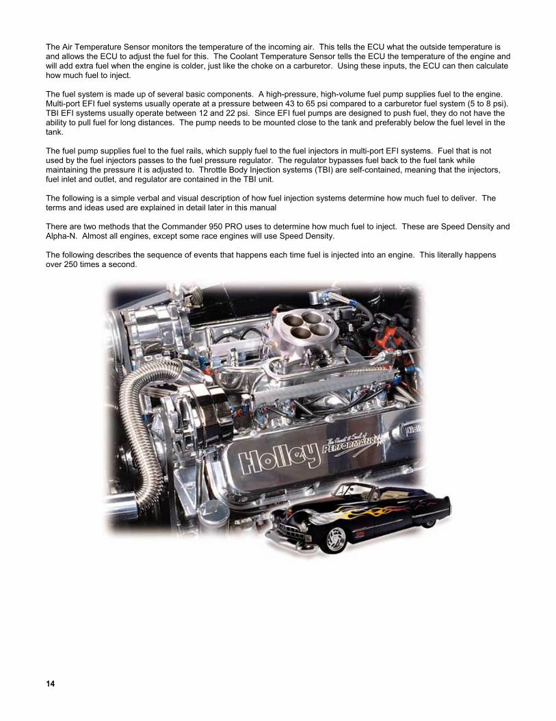
The Air Temperature Sensor monitors the temperature of the incoming air. This tells the ECU what the outside temperature isand allows the ECU to adjust the fuel for this. The Coolant Temperature Sensor tells the ECU the temperature of the engine andwill add extra fuel when the engine is colder, just like the choke on a carburetor. Using these inputs, the ECU can then calculatehow much fuel to inject.
The fuel system is made up of several basic components. A high-pressure, high-volume fuel pump supplies fuel to the engine.Multi-port EFI fuel systems usually operate at a pressure between 43 to 65 psi compared to a carburetor fuel system (5 to 8 psi).TBI EFI systems usually operate between 12 and 22 psi. Since EFI fuel pumps are designed to push fuel, they do not have theability to pull fuel for long distances. The pump needs to be mounted close to the tank and preferably below the fuel level in thetank.
The fuel pump supplies fuel to the fuel rails, which supply fuel to the fuel injectors in multi-port EFI systems. Fuel that is notused by the fuel injectors passes to the fuel pressure regulator. The regulator bypasses fuel back to the fuel tank whilemaintaining the pressure it is adjusted to. Throttle Body Injection systems (TBI) are self-contained, meaning that the injectors,fuel inlet and outlet, and regulator are contained in the TBI unit.
The following is a simple verbal and visual description of how fuel injection systems determine how much fuel to deliver. Theterms and ideas used are explained in detail later in this manual
There are two methods that the Commander 950 PRO uses to determine how much fuel to inject. These are Speed Density andAlpha-N. Almost all engines, except some race engines will use Speed Density.
The following describes the sequence of events that happens each time fuel is injected into an engine. This literally happensover 250 times a second.

15
2.1 Speed Density
1. Engine speed (1000 RPM) and manifold pressure from the MAP sensor (38 kPa) are read by the ECU. From these values,it obtains a number from the base fuel map (32).
2. The ECU then looks at the reading from the Air Temperature Sensor and may modify the fuel value. In this case it adds.8% more fuel.
3. The ECU looks at the reading from the Engine Coolant Temperature Sensor and may further modify the value. In this caseit is at 100% (operating temperature) so it does not add or subtract more fuel.
4. The ECU will look and see if the engine is accelerating based on the Throttle Position Sensor. In this case the enginespeed is not changing.
5. From these values, it will calculate the amount of fuel that the user has programmed to deliver which is called thepulsewidth. If the engine is closed loop, it will modify this value to maintain the desired air/fuel ratio.
The following flowchart (Figure 1) illustrates this example:
BASE FUEL MAPVALUE
100.8%
1000 RPM 38kPa
32
47°F
AMOUNT OF FUEL
INJECTED
(Pulse Width)
3.1 ms
ENGINESPEED
MANIFOLDPRESSURE
(MAP Sensor)
MANIFOLD AIRTEMPERATURE
MODIFIER(Air Temp Sensor)
ACCELERATIONENRICHMENT
(Change in TPS andMAP Sensor)
COOLANTTEMPERATURE
MODIFIER
(Water Temp Sensor)
100.0%
0.82v
CLOSED LOOPFEEDBACK TO
MAINTAIN DESIREDAIR/FUEL RATIO(Oxygen Sensor)
CLOSED LOOPOR
OPEN LOOP?
AMOUNT OF FUEL
INJECTED
(Pulse Width)
3.8 ms
Open Loop Closed Loop
180°F
100.0%
No Change
Sensor DataInput
ECU Calculationsand Adjustments
Key:
Figure 1 Engine at Operating Temperature; Speed Density ECU Strategy Flowchart

1616
2.2 Alpha-N
An Alpha-N system is similar to a speed density EFI system, except that for step 1, the ECU will look at engine speed and theposition of the Throttle Position Sensor, instead of the MAP Sensor, to determine the value from the base fuel map. Thefollowing flowchart (Figure 2) illustrates this example.
100.8%
1000 RPM 40
47°F
ENGINE
SPEED
THROTTLEPOSITION
(TPS)
MANIFOLD AIRTEMPERATURE
MODIFIER(Air Temp Sensor)
ACCELERATION
ENRICHMENT(change in TPS and
MAP Sensor)
COOLANTTEMPERATURE
MODIFIER(Water Temp Sensor)
100.0%
180°F
BASE FUEL MAP
VALUE
32
AMOUNT OF FUEL
INJECTED
(Pulse Width)
3.1 ms
0.82v
CLOSED LOOPFEEDBACK TO
MAINTAIN DESIREDAIR/FUEL RATIO
(Oxygen Sensor)
CLOSED LOOPOR
OPEN LOOP?
AMOUNT OF FUEL
INJECTED
(Pulse Width)
3.8 ms
Open Loop Closed Loop
100.0%
No Change
Sensor DataInput
ECU Calculationsand Adjustments
Key:
Figure 2 Engine at Operating Temperature – Alpha-N ECU Strategy Flowchart

17
3.0 SKILL LEVEL REQUIRED
Installation of the COMMANDER 950 PRO intake system and the ECU requires approximately the same level of skill andexperience to replace or service an induction system consisting of a carburetor and conventional intake manifold (as well asbasic wiring skills for the installations of the ECU).
Tuning of the system requires basic computer skills and a basic knowledge of engine and fuel injection principles. Theinformation needed to tune this system is included in this manual. Read it thoroughly.
Installation of the actual EFI system hardware is included in hardware installation manuals with each kit.
Tuning your EFI system is an ongoing project, until you get it dialed in for all conditions. Be patient.
NOTICE: If you are not absolutely certain that you have the skills and experience required to perform theseprocedures, we strongly recommend you have this system installed and tested by a technician withspecialized training in EFI and fuel systems service.
4.0 TOOLS REQUIRED FOR INSTALLATION
The following is a list of materials, which may be needed, depending on the application.
Laptop PC w/ Windows 3.1, 95, 98, ME, NT, 2000, and serial communications port (min. graphics required=800 x 600) Digital Volt-Ohm meter Screwdriver set Drill and assorted bit sizes Hole saw (2”) or Greenlee punch Timing/Advance Light (Dial back recommended) Standard wrench set Standard socket set Fuel pressure gauge Wire terminal pliers Electrical tape Zip ties 14 gauge wire
The following is a list of parts that may be required to complete this installation (dependent on the application).
534-138 GM small cap HEI adapter (included with GM MFPI kits) 534-139 Ford TFI adapter (included with 5.0L Ford kits) 538-13 Two bar MAP sensor for applications with 0-14.7 PSI of boost 538-23 Three bar MAP sensor for applications with 14.7-29.4 PSI of boost 534-136 Knock Sensor wiring kit 534-134 Cooling Fan Relay kit 534-135 Crank Trigger wiring kit N/A Aftermarket Crank Trigger (required for LT1 engines)
5.0 ELECTRICAL CONNECTIONSProper installation of the wiring harness and all electrical connections is critical for proper and reliableoperation of any EFI system. Damage to the ECU can also result from improper wiring.
Wiring diagrams are provided for reference during the connection of electrical components. These diagrams show theconnectors included with the wiring harness and table shows the color codes and connections for all of the loose wires withoutconnectors. See Appendix 10 for the wiring harness diagram.
NOTE: Some of the wiring schematics include wiring for optional kits, such as a cooling fan kit.

1818
5.1 Step-by-Step Wiring Harness Installation
NOTE: It is advised to leave the battery completely disconnected until the installation of the entire system iscompleted.
1. ECU MOUNTING – The ECU should be mounted as far away from the ignition box as is feasible (minimum 6”). The ECUmust be installed in the vehicle in a location free from moisture and dirt. The glove box area is usually a good location inmost vehicles. There are sheet metal screws included for this purpose. The ECU must be grounded. If you mount it on anon-metallic surface (ex. fiberglass body), run a 14 gauge ground wire to the chassis.
2. HOLLEY WIDE-BAND OXYGEN SENSOR CONTROLLER – This unit can be mounted either inside the vehicle or enginecompartment. Do not put in direct contact with water or road debris and keep away from excessive heat.
2A. NON-HOLLEY WIDE-BAND OXYGEN SENSOR CONTROLLER – If using a non-Holley wide-band oxygen sensor controller, refer to the manufacturer’s instructions for its installation. In order for the Commander 950 PRO to use such adevice for closed loop operation, a calibrated 0-5 volt output from the wide-band sensor controller must be connected to thepurple O2 sensor signal wire on the Commander 950 PRO. The red power wire and black ground wire also contained in theO2 sensor 3 pin weatherpack connector can also be used to power and ground the wide-band controller unit. This isdesirable so that the wide-band controller is only powered when the engine is running. If the wide-band controller has aseparate analog output ground, it is advisable to connect this to a very good vehicle chassis ground. See the wiringschematics in the back to find the O2 sensor connector.
Make sure the proper voltage vs. air/fuel curve is entered into the O2 parameters. It is the responsibility of the customer tomake sure this curve is accurate or engine damage can result.
3. WIRING HARNESS - The wiring harness will need to be fed through the firewall in the vehicle. Drill a 2 inch diameter holeand feed the harness through it. A grommet is provided for this hole so the harness will not be damaged. Be very carefulthat the hole you drill does not interfere with items like wiring harnesses, heating, or AC systems.
4. CONNECT WIRING HARNESS - After the harness is routed through the hole connect it to the ECU. Route the rest of theharness into the engine compartment.
5. INSTALL RELAY - A system power relay is included. The relay holder for it is about 3 feet from the ECU connection. Therelay can be mounted inside the interior or in the engine compartment. Decide where you want it and secure the relay. Asheet metal screw is provided for this purpose. Be careful that you don’t drill through the firewall and damage something.Mount the relay and attach it to the harness.
6. INSTALL FUSE - The 15 amp fuse needs to be installed in the fuse holder. The fuse is included and the fuse holder islocated near the ECU. Install it now.
5.2 Non-Terminated Wire Connection
Next, the non-terminated wires will be connected (Figure 3). The following chart provides an overview. However, each one willbe described separately.
NON-TERMINATED WIRE COLOR AND DESCRIPTION WIRE CONNECTION LOCATIONBlack Ground connectionRed with fuse +12 Volt, attach to the batteryRed/White Switched +12 volt power (make sure this has power during
cranking also)Orange/Red AC Request or other programmable inputs [+12v] (this is
an optional wire)Light Blue Park/Neutral or other programmable inputs [Ground] (this
is an optional wire)Green Black +12 volt fuel pump or fuel pump relayYellow Wire See text below
WARNING! DO NOT USE THE YELLOW WIRE IF A CAPACITIVE DISCHARGE (MSD STYLE) IGNITION IS BEING USED.THE ECU WILL BE DAMAGED.
WARNING! Keep all wires away from hot exhaust components. Bare or frayed wires can result in electrical shortcircuits, which can cause system or vehicle damage, or a fire hazard resulting in property damage, seriousinjury, and/or death.

19
Figure 3 Non-Terminated Wiring Diagram
1. BLACK WIRE - Connect the black wire to a solid chassis ground with the ring terminal provided. The best place to connectis the negative side of the battery.
2. RED WIRE - Connect the red wire directly to the positive side of the battery with a ring terminal provided.
3. RED/WHITE WIRE - Connect the red wire with the white stripe to a 12 volt source which only has power when the ignitionswitch is on. Make sure it has power when the key is in the “start” position also.
4. LIGHT BLUE WIRE - The light blue wire is a programmable input. It does NOT have to be used. It is triggered by aground. See Chapter 13 for more input/output information. It has the following uses:
Park/Neutral Input – Triggered from a ground from the neutral safety switch. It allows for the IAC to a programmable valuewhen the vehicle is put into gear to prevent stalling. It is rare that it is needed for this function. 99.8% of stalling problemswhen a vehicle is placed into gear is from improper tuning. This wire needs to be GROUNDED when the vehicle is in parkor neutral.
Internal Data-logger Start – This input can be used to trigger the internal data-logger. It is best if this is a momentaryground, but can be a non-momentary ground also. See Chapter 12 for more info on the internal datalogger.
Timing Retard – This input can be used as a ground input to trigger a timing retard.
5. ORANGE/RED WIRE – The light blue wire is a programmable input. It does NOT have to be used. It is triggered by a +12volt input. See Chapter 13 for more input/output information. It has the following uses:
AC Request - Used to raise the idle speed a programmable amount when the air conditioning is turned on. Depending onthe engine and desired idle speeds, it is unlikely that it is needed. This wire needs a +12 volt input to raise the idle speed.This wire would be connected directly to the AC compressor.
Internal Data-logger Start – This input can be used to trigger the internal data-logger. It is best if this is a momentary +12vinput, but can be a non-momentary also. See Chapter 12 for more info on the internal datalogger.
Timing Retard – This input can be used as a +12v input to trigger a timing retard.
6. GREEN/BLACK WIRE - The green wire with black stripe is used to activate the fuel pump. We advise using a separaterelay to power the pump and the green/black wire to energize the relay (required with pumps that draw current over 10amps). See Appendix 9 for important information on fuel pumps. Connect ground side of pump to good chassis ground.
7. YELLOW WIRE – The yellow wire (bundled with the 4 pin ignition connector) is one of several wires that can be used forRPM input. This wire should ONLY be used if using a stock points type ignition, if the ECU is NOT being used to controlignition timing, AND a capacitive discharge (MSD type) ignition system is NOT being used. See the schematics in the backof the manual for proper wiring.
WARNING! DO NOT USE THE YELLOW WIRE IF A CAPACITIVE DISCHARGE (MSD STYLE) IGNITION IS BEING USED.THE ECU WILL BE DAMAGED.

2020
5.3 Plug-In Connections
NOTE: See Appendix 10 for diagrams.
1. Air Charge Temperature Sensor – Find the 2 wire connector with the BLUE and BLACK/WHITE wires. Plug this into theair temperature sensor, which is located in the intake manifold on MPFI applications. For TBI applications, the air tempsensor is located next to the injector pod.
2. Coolant Temperature Sensor - Find the 2 wire connector with the BROWN and BLACK/WHITE wires. Plug this into thecoolant temperature sensor, which is located in a coolant passage.
3. Throttle Position Sensor (TPS) - Find the 3 wire connector with the BLACK/WHITE, GREEN, and ORANGE wires. Plugthis into the TPS located on the throttle body.
4. Idle Air Control (IAC) Motor – Find the 4 wire connector with the PURPLE wires. Plug this into the IAC Motor, which islocated on the throttle body.
5. Narrow-Band Oxygen Sensor (O2)* – Plug this into the oxygen sensor, located in the exhaust system. It is the 3 wireconnector with a RED, PURPLE, and BLACK wire. Route the wire away from heat to avoid damage to the sensor or wire.
6. Wide-Band Oxygen Sensor* – Plug the 3 wire connector with a RED, PURPLE, and BLACK wire into the 3 wire connectorfrom the Holley wide-band oxygen sensor controller. Plug the 8 wire connector from the wide-band oxygen sensor controllerinto the wide-band oxygen sensor. The four-wire connector is for a display (not included) *A system includes either anarrow-band oxygen sensor or a wide-band oxygen sensor depending on system options.
7. Manifold Absolute Pressure (MAP) Sensor – Locate the 3 wire flat connector with the following color wires:BLACK/WHITE, ORANGE, and RED/BLACK. Plug this connector into the MAP sensor. Two and Three bar MAP sensorsare optional in some kits. The base kits come with a one bar MAP sensor. If a two or three bar MAP sensor is used, it mustbe selected in the “Engine” parameters when you get the computer hooked up. The two and three bar MAP sensors shouldinclude a connector that may have to be changed on the harness.
8. Injector Harness – The harness for the fuel injectors is separate from the main harness. For multi-port systems, route theinjector harness as desired. This harness plugs into the 5 wire connector on the main harness. TBI systems also plugdirectly into this connector.
5.4 Ignition Wiring
NOTE: Appendix 10 in the back of the manual includes wiring diagrams to wire the following:
Large Cap Computer Controlled GM HEI – Plugs directly into 4 pin weatherpack ignition connector in Comm 950 harness.
Small Cap Computer Controlled GM HEI – Requires adapter (PN 534-138) that plugs into the 4 pin weatherpack connector inthe Commander 950 harness. This adapter is included with complete Chevrolet SB and BB Multi-port EFI systems.
Ford TFI – Works with any Ford TFI electronic distributor. Requires adapter (PN 534-139) that plugs into the 4 pin weatherpackconnector in the Commander 950 harness. This adapter is included with complete Ford Multi-port EFI systems.
Large Cap Non-Computerized HEI – This distributor uses mechanical and vacuum advance and is not capable of having theCommander 950 control timing.
Crank Trigger CD Ignition Systems – The Commander 950 can control the timing on any engine that uses a crank trigger(magnetic or Hall effect) and capacitive discharge ignition box.
Non-Computer Controlled Inductive Ignition Systems – Any inductive (non-CD) ignition system (most stock ignition systemsare inductive) can be used to provide an RPM signal to the Commander 950. These systems will not allow the Commander 950 to control ignition timing. Points ignition and the Mallory Uni-lite systems fall into this category.
Magnetic Pickup Distributors with Mechanical Advance – Standard magnetic pickup mechanical advance distributors suchas a Holley or MSD can be used with a CD ignition system. The C950 will not be able to control timing. Connect theyellow/black ignition wire to the tach output connection on the CD box.
GM LT1 Engines – These engines require the use of a crank trigger and CD ignition box. Follow the wiring instructions for acrank trigger CD system.

21
NOTE: It is not advisable to use a magnetic pickup distributor to directly feed the magnetic trigger input of the C950. If themagnetic pickup distributor is connected to the C950 via the inductive pickup trigger wires, the pickup/rotor/cap phasingmust be corrected. This operation may require a phaseable cap or rotor or possibly machining to the distributor and istherefore beyond the scope of most users. Even with the phasing corrected, the electrical noise inside the cap may bestrong enough to cause tuning problems. It is advised to use a crank trigger system or a computer-controlleddistributor.
Reconnect the battery cable and check voltages. NOTE: NEVER CONNECT THE YELLOW WIRE TO A CAPACITIVE DISCHARGE IGNITION SYSTEM.
6.0 SOFTWARE INSTALLATION, SOFTWARE OPERATIONAL DESCRIPTION,COMPUTER OPERATION, & FUEL MAP DOWNLOADINGAn IBM compatible laptop computer is required for use with the COMMANDER 950 PRO. The computer must be capable ofrunning Windows 3.1, Windows 95, 98, ME, 2000 or Windows NT. The laptop must also have a graphics resolution of at least800 x 600 to view all areas of the screen. The computer must have a Comm port.
6.1 Software Installation
6.1.1 Windows 95, 98, NT, ME, 2000
1. Insert disk 1 of 3.
2. Select the START menu at the bottom left hand area of the computer screen. On the pop up menu select RUN.
3. Type A:\SETUP.EXE in the command line box and click OK. This will begin the installation of the software. Follow the on-screen information.
6.1.2 Windows 3.1
1. Insert Disk 1 of 3 into the floppy drive.
2. From the Windows Program Manager menu, select run. Type a:Setup and press enter. This will begin the installation ofthe software. Follow the on-screen information.
6.2 Basic Computer OperationOnce the software is installed, a Commander 950 Pro icon should appear on the main computer screen. When you double-mouse click on this icon, the software should start. There is a communications cable that needs to be hooked up to the ECU (itis connected to the harness near the ECU) for you to program and view data in the ECU. This cable needs to be plugged intothe communications (comm) port, which is usually in the back of a laptop computer. The computer usually recognizes this commport as comm 1. Sometimes it may be comm 2. The proper port must be selected in the software in order for the computer tocommunicate with the ECU. If comm 1 does not work, change the software to comm 2.
6.3 Software Operation and NavigationThe Commander 950 PRO is a Windows-based software. It functions the same as all other windows software. Pull-downmenus are selected with the mouse. These are then opened to view the various tables.
Software Data Capture – When a window is opened, the software checks for the ECU. If it is present (powered up andconnected to the serial cable), the computer will get the latest data from the ECU. This ensures the user and the PC are alwaysusing the most up-to-date information. If the ECU is not connected, the PC will just use the information it has in memory. If nomap has been loaded into the PC (via file—load operation) and no ECU is present, there will be nothing in memory and zero willbe displayed for nearly all variables.
These tables can be edited with the ECU connected and powered or without the ECU powered. With the laptop computerconnected and powered, you can tune the vehicle with the engine running and with the vehicle being driven. If the laptop is notconnected to the ECU, you can change the files, and then later send the changes to the ECU.

2222
Editing with the ECU Connected and Powered – One of the most important features of the Commander 950 PRO is theability to make real-time changes when the engine is running. In order to do this, the ECU must be connected to the computer,and the ignition switched on (the engine does not have to be running). When a value is entered and the “Enter” key, Arrowkey, or Tab key is pressed, the value is instantly sent to the ECU and the old value is gone.
Editing with the ECU not Connected – Values can be changed when the computer is not connected or the ignition notswitched on. However, for these values to be entered in the ECU, the entire file must be sent to overwrite what data is currentlyin the ECU. The following shows how to open, send, retrieve, and save a file. When editing tables without being connected tothe ECU, you must also press the “Enter” key, Arrow key, or Tab key to enter the value.
Opening a File into the Computer – To open a file into the computer perform the following steps:1) Select “File” and “Open Data from Disk”2) Select the file you want to open, either from the hard drive or a disk. (This is explained in “Step-by-Step Initial Startup”).3) Hit “Enter” or click on “Ok”4) The file is now in the computer.
Figure 4
Sending a File to the ECU – To send a file to the ECU perform the following steps:1) Open a file as described above. Do NOT go to any of the other areas in the software, as this will retrieve and corrupt
the data that you just opened.2) Make sure the ignition is on. After the file is opened, immediately go to “File” and “Send ECU Data”. It will take about one
minute to send the data. When the hourglass changes back to your mouse pointer, the file has been sent.
Retrieving a File from the ECU – You would want to retrieve a file from the ECU when you want to save it to the hard drive ofthe computer or to a disk. To retrieve a file, make sure the ignition is on and go to “File” and hit “Retrieve ECU Data”. This pullsthe data from the ECU to the computer.
Saving a File to the Computer – It is highly recommended to save your file before making any major changes. If thechanges don’t work well you can send the previous file back. To save a file from the ECU, first retrieve it from the ECU and thengo to “File” and “Save Data to Disk”. This file will be available to send if you ever need to.
Force Default Values – When loading an older map not made for the PRO software, several of the default values will not be setproperly. If these values are not set, an engine will either not start or run very poorly. This feature will allow for these newvalues to be updated to values that should at least allow for the engine to start and be driveable. To update the values, first loadthe old map into the ECU. The laptop must be connected and the ignition must be turned on. Under “File”, hit the “Force DefaultValues” key. This will update the values to usable values. They then can be fine-tuned for the specific application.
Print All – Will print all tables and maps to a printer.
Hot Key Navigating – There are 5 “Hot Keys” that can be used to quickly change from one screen to another. The screens thatcan be navigated between are the following:
Map Screen Hot KeyFuel Map Screen Control + FSpark Map Screen Control + SAcceleration Enrichment Map Screen Control + AModifiers Map Screen Control + MClosed Loop Parameters Control + O
NOTE: Remember these. These commands will be needed later on for tuning. You must already be in one of these fivescreens before you can use the hot keys to navigate to the others.
Mouse Free Navigating – Sometimes a laptop mouse is hard to use. The C950 PRO software can be operated without it.From the main window, press “Alt” and then the underlined letter of the window or menu you want to open (i.e. press “Alt” andthen “F” to open the “file menu”). Different locations can be navigated by pressing the “Tab” key. When in any of the windowswith tables (such as the fuel and spark tables), it is easier to use the arrow keys, so you can move quickly to the exact spot youwant. To exit a window, press the “Esc” key. When making changes, the new value isn’t actually sent until you move off the cellyou are working on or press the “Enter” key.

23
Making Changes to Multiple Cells at Once – In the fuel and spark maps, changes to entire sections of the maps can be madevia “cell action” feature. Using the mouse, click on a cell in the area that you wish to modify. Next, click on the diagonallyopposite cell. The cells in this region will be highlighted in yellow and a small window will appear. Type the operation that youwish to perform (+ for addition, - for subtraction, * for multiply, / for divide, and % for adding or subtracting a percentage) and thevalue you wish to modify the cell amount. For example, by typing a “+10”, the ten units will be added to all of the highlightedcells. Typing a “*1.2” would multiply all the highlighted cells by 1.2. This feature is very helpful and should be used whenneeded.
6.4 Base MapsBase maps are supplied. Choose the one that is closest to your application. If one does not seem to work well, choose another.You will always have to perform additional tuning for the vehicle to operate best. That is the benefit of programmable EFI.This tuning may be small changes or large changes, depending on your engine and vehicle. These base maps will be installedin the Commander 950 PRO directory when the software is installed. There is also an additional sheet supplied that describeswhat these are for. New base maps can be found on the Holley website (www.holley.com). These are self-extracting zip files.Save them to a directory and double click on them. This will unzip them and allow them to be loaded to the ECU. See theinformation above on sending these maps to the ECU.
Note that the maps are separated by using a narrow-band or wide-band oxygen sensor. The maps for a narrow-band sensorstart with a NB and the wide-band maps start with a WB for systems using a Holley wide-band oxygen sensor. Select dependingon which oxygen sensor you have.
6.5 Advanced and Beginning UsersNot all screens may look exactly like they are shown in the manual. Some variables are considered too advanced for the first-time user and are not needed until the tuning process is nearly complete. These variables have been hidden from view. Whenyou are ready to adjust these parameters (and you may never need to use them), go to “About” and then “Version”. Check the“Advanced User” box and all variables will be visible.
7.0 STEP-BY-STEP INITIAL STARTUP INSTRUCTIONSAt this point you should have the mechanical installation complete. The Commander 950 PRO software should be installed inthe laptop (Chapter 6.1) you will use for tuning. The next section is the first attempt to start the engine. Base maps are includedfor different engine combinations. If the base map is close to your application, then the vehicle should fire and run. If the basemaps that you try will not start and allow the engine to keep running, go to the detailed tuning information that is included in theStep-by-Step Basic Tuning (Chapter 8.0).
1. CHECK FUSES/RELAYSMake sure the 15 amp fuse is installed in the fuse holder in the main red power wire which is located near the ECU.Make sure the relay is installed in the relay holder.
2. CONNECT COMPUTER CABLEConnect the communications cable to the serial communications port on the computer and to the round connector onthe main harness near the ECU.
3. PRIME FUEL SYSTEMTurn the ignition key to “Run”, not start. You should hear the fuel pump energize for about 5 seconds, then shut off.This allows for the pump to pressurize the fuel system. When the vehicle is starting and runs, the pump will turn backon. If you do not hear the pump turn on when the key is turned on, see Appendix 4. After the pump is energized,check the entire fuel system for leaks. You can shut the key off, wait about 10 seconds, then turn it back on to re-energize the pump. It takes 10 seconds in the key “Off” position for the ECU to reset. You may have to do this severaltimes if the entire fuel system is dry. When the system is pressurized, you can hear the speed of the pump slow down.You will also see the pressure come up on a fuel pressure gauge.
4. CHECK FUEL PRESSUREDo an initial check of the fuel pressure when the key is turned on. See the hardware installation manual forinformation on installing a fuel pressure gauge on your particular system. It is critical that the pressure be checkedand adjusted. The recommended base setting for Multi-port systems is 44 psi +/-2 psi and Throttle Body Injectionsystems is 21 psi +/-1 psi. These settings can be raised or lowered if an injector is selected that is too big or too small.Again, you may need to energize the pump a few times if the fuel system is dry.

2424
NOTE: There is a vacuum line going to the fuel pressure regulator. This is needed to compensate for vacuum present in theintake manifold. Make sure you always use this vacuum line. When the engine is running and the vacuum line ishooked to the regulator, the pressure seen on the fuel pressure gauge will be lower depending on how much vacuum ispresent. 2 inches (Hg) of engine vacuum will lower the fuel pressure 1 psi. For example, 15 inches (Hg) of enginevacuum will lower the fuel pressure about 7 psi. This is normal.
If the pressure is not checked and set, you will possibly have problems later when tuning the engine. There are goingto be instances when you will need to increase or decrease the pressure if your injector size is not adequate for yourengine. That will be discussed later. At this time, check for fuel leaks. After the engine is started you will then need tore-check for leaks.
5. IGNITION CHECKIt is very important that you are sure that you installed the distributor so that the timing will be close when the engine isfirst started. If it is not, the vehicle may not start or run very poorly. If you are not sure, review the hardware installationmanual for proper distributor installation.
6. IDLE SETTINGSThe throttle blades need to be open enough so that an adequate amount of air can enter the engine, which will allowthe engine to idle. If they are too far closed, not enough air will be available and it is possible that the engine will notstart. The bigger the engine, the more air it will need at idle. Make sure that throttle plates are cracked open. It isbetter that they are open too far than not far enough. If they are open too far, the engine will just idle too high. If thishappens close them far enough until the idle air control motor takes control of the idle.
7. LOAD BASE MAPNext we will load the base map (base map refers to a complete EFI program) that is closest to your engine and vehiclecombination. This base map should allow for the vehicle to start and possibly drive but will always need tuningfor optimum performance. Perform the following steps:
A) Turn on the computer and start the Commander 950 PRO software.
NOTE: Chapter 6.3 reviews how to open, send, retrieve, and modify data. The steps listed must be followedor you will corrupt data in the ECU.
B) Base maps should have been loaded in to the C:\Cmdr950 directory when the software was installed. Open thisdirectory and select the base map closest to your application. Note that there are base maps for standard narrow-bandoxygen sensors designated by having a “NB” at the beginning of the map name and there are maps for systems withHolley wide-band oxygen sensors will have a “WB” at the beginning of the map name.
C) Mouse click on the base map that most closely fits your application and mouse click on the “Ok” button. See theincluded sheet that has descriptions of the base maps.
D) Making sure the ignition key is on, and making sure you don’t enter any of the screens in the software until you sendthe ECU data, select “File” and “Send ECU Data”. It will take about one minute to send the map. When it is finishedsending, the mouse pointer should change back from the hourglass.
E) Your base map is now loaded.
8. SELECT ENGINE PARAMETERSYou now need to go in and verify several parameters for your particular combination that must be correct for the engineto start after the base map has been sent. The parameters are located under “Hdwr Settings” and then “EngineParameters”. Go to this location. All changes MUST be done with the key on or they will not be changed in theECU. Any changes in “Engine Parameters” must be done with the engine NOT running but with the key ON. Thefollowing items MUST be correct for the engine to start. If they are not, choose the proper selection at this time. SeeFigure 5.
NOTE: When entering a numerical value, click the mouse on the cell you want to enter. This should highlight it in blue. Thentype in the number. Then hit the “Enter” key or the “Tab” key and this will send the value to the ECU.

25
Figure 5 Engine Parameters Screen
Record your selection in the spaces provided.
_________ Cylinders – Pick 4, 6, or 8
_________ Port Fuel Injection or Throttle Body Injection – Select Multi-Port or Throttle Body fuel injection. If multi-port isselected, you can select whether fuel is injector once per revolution (1 PS per 1 rev.) or once per two revolutions (1PW per 2 rev.) The one pulse per two revolutions is primarily used when very large port injectors (50+ lb/hr) areused.
_________ Ignition Type – See (Appendix 1—Hardware Settings) FOR DETAILED INFORMATION if you are not absolutelysure what type of ignition you have. If you have a computer-controlled (has NO mechanical or vacuum advance)GM HEI (1981 and up), select “GM HEI”. If you have a Ford TFI, select “Ford TFI”. If you have a Hall effect sensorconnected, select “Hall Effect”. If you are connected to a magnetic pickup, select “Inductive Pickup”. If you are notusing timing control and DO NOT have a Capacitive Discharge ignition system, select “Fuel Only (coil-)”. NEVERconnect the yellow wire to the coil on a Capacitive Discharge ignition system such as an MSD. This will destroy theECU.
_________ Load Sense – Select “Speed Density” or “Alpha N”. See Chapter 1.19 for information on these.
_________ RPM Below Which Unit is Alpha-N – This features is designed for engines that have very low vacuum at idle.This allows for an engine to operate in Alpha-N mode below a certain RPM and Speed Density above that. Themajority of users will want to enter a “0”. This will allow Speed Density operation all the time. If low vacuum existsat idle that makes using speed density operation at idle difficult, a value such as “1500” may be beneficial.
_________ MAP Sensor – Select whether you have a 1, 2, or 3 bar MAP sensor. See Chapter 1.10 for information on these.
_________ Throttle Sensor Values – The following all pertain to throttle position sensor settings
WOT TPS Value – This Is the TPS value at wide-open throttle. With the ignition on and the engine not running,open the throttle all the way and look at the TPS value in the data monitor. Enter this value.Clear Flood TPS Position – This is the value, that above which, no fuel will be injected when the engine iscranking. This is just in case the engine should ever get flooded, that no fuel will be injected when the throttle isdepressed past this value. A value that is 50 below the WOT value is typically good.TPS Noise Value – This value corresponds to how much of a throttle change needs to be made before the ECUdetects it as having changed and not just electrical “noise” having caused a sensor change. Numbers of 1 or 2 willwork well.

2626
Max TPS for Closed Loop Operation – This is the value above which the engine will go open loop. Runningclosed loop at WOT with a narrow-band oxygen sensor can damage the engine by running too lean. If a wide-bandoxygen sensor is being used it is possible but not usually advisable to run closed loop at WOT. See the wide-bandtuning section for more information. Naturally aspirated engine normally go open loop at about 2/3 throttle. Forcedinduction engines may go open loop as soon as 1/3-1/2 throttle.Max TPS for Idle – A TPS value above this tells the ECU that an idle condition is no longer encountered. This valueshould be 4-5 above the actual TPS value. It is VERY important that this value is set properly otherwise featureslike idle spark control and decel fuel cutoff will not work properly. Make sure this number is changed if the idle screwis moved.
_________ Ignition Reference – See Appendix 1—Hardware Settings for the proper number. This is VERY important that itbe correct. It provides the ECU with information so that it knows when Top Dead Center (TDC) will occur.
_________ Decel Fuel Cutoff – This feature is for better driveability, fuel economy, and emissions. This allows for the fuel tobe shut off when a vehicle is decelerating. This can help stop an overly rich condition when decelerating and stop“bucking” in a manual transmission vehicle. The Decel Wait Time is the time it takes to shut the fuel off when thethrottle is released. The RPM value added to idle where turns on is the RPM number above the desired idle, thatthe fuel will “kick back in”. It is essential that the “Max TPS for Idle” value, which is found under “Spark” and “IdleSpark Control” is properly entered. This value should be about 4 more than the idle TPS position.
_________ TBI Switch 2-4 and TBI Switch 4-2 – If you have a Throttle Body Injection System, see Appendix 2—TBI SpecificTuning Information to set this. This is important.
_________ Load Scale – Set the values to what is shown in the above picture if using a speed density system with a 1 barMAP sensor. If using a 2 or a 3 bar MAP sensor, first select 1 bar MAP sensor, enter the numbers shown above,and then select 2 or a 3 bar MAP sensor. The scale will then be changed appropriately. The real intent of thisfeature is for custom scaling when using a 2 or 3 bar MAP sensor or Alpha-N system. For example, if a person isusing a 2 bar MAP sensor, but the engine is only making 5 PSI of boost, then the MAP scale should only go from 0to 135 Kpa. This will provide the full range needed, but give the most resolution possible. An Alpha-N map normallygoes from 0-255 (TPS position), but if it really goes from 40 to 175 than you can make the TPS scale match theactual TPS range giving full use of the fuel map.
Setting these parameters will allow for the ECU to receive a RPM signal and fire the injectors. If the base map is sufficientlyclose, the other parameters do not have to be changed to see if the car will start. They will be explained and adjusted later.
9. CLOSED LOOP/OXYGEN SENSOR PARAMETERSThese parameters must have basic selections correct. Base maps are separated by whether you have a narrow-bandsensor or wide-band sensor. If you selected that correctly, and are using a Holley supplied oxygen sensor, then theseparameters should all be good starting points. See Chapter 9.1A for more details if using a narrow-band sensor andChapter 9.1B if using a wide-band oxygen sensor.
10. SAVE PARAMETERSIt is recommended that you save your map to the computer hard drive anytime you make changes, that way you canalways go back to a previous version. At this time you should save that map that has the correct engine parameters. To save the map perform the following:A. Turn the ignition on.B. Go to “File” and “Retrieve ECU Data”C. Go to “File” and “Save Data to Disk”D. Select the directory that you want to save it toE. Type in a name for the mapF. Either hit “Enter” or click on “OK”
The map is now saved on the computer hard drive in the directory you selected. It may be opened and sent back to theECU if needed. The default directory is “CMDR950”.
11. Next, we will verify that all of the sensors are working correctly. Select “Fuel” and “Main Fuel Map”. This brings up thebase fuel map. At the top is the Data Monitor, which among other items, shows all the outputs from the sensors.Several of these will be verified before we start the engine. The ignition key needs to be ON to view the data. Thefollowing picture shows typical key on values.
If any of these sensors are not reading correctly, see the troubleshooting area and correct the problem beforeattempting to start the vehicle.

27
Figure 6 Data Monitor Showing “Key On” Values
Check the following sensor outputs. After each, record the value in the space provided.
_________ MAP (Manifold Air Pressure) – The manifold air pressure when the engine is not running should bebetween about 88 and 94 with the engine not running. In higher elevations it will be lower. Possibly as lowas 75-80.
_________ TPS (Throttle Position Sensor) – The position of the TPS needs to be greater than 5 with the throttleclosed and when the throttle is fully opened, it must be less than 255. As the throttle is opened, the TPSvalue should evenly increase from a low to a high value. There is not a specific value or voltage it needs tobe at. But, there are parameters that must be entered depending on what it is. These will be entered later.The TPS on Holley TBI and MPI systems should not need to be changed as they come from the factorypreset.
_________ MAT (Manifold Air Temp (F)) – The manifold air temperature should be very close to the actualtemperature of the air when the engine is off and cold.
_________ V Bat – (Battery Voltage) – The battery voltage should not be less than 12 volts. It should be over 13.5volts with the engine running. Proper voltage is essential to an EFI system. If your battery or chargingsystem is not adequate, it must be fixed.
_________ Coolant (F) (Coolant Temperature) – The coolant temperature should be about the same as the manifoldair temp (or it should be close to the same as your temperature gauge) if the engine has not been running.
ALL OF THESE SENSORS MUST BE WORKING FOR THE ENGINE TO RUN AND OPERATE. IF THEY ARE NOTREADING CORRECTLY, FIND OUT WHY.
11. Now, try to start the car. Make sure the key is off, turn it on, let the fuel pump prime until pressure is built, and start the car.You should hear the pump speed slow down when the system is pressurized. If the base map is close, it shouldimmediately fire and run. If it does not fire or stay running refer to the Basic Tuning-Chapter 8.0. You should not and donot want to move the gas pedal when trying to start the vehicle.
12. Make sure that the fuel is not excessively rich so much as to damage the engine or catalytic converters. The most obvioussign of this is black smoke coming from the exhaust. If it is, shut it off and refer to the Basic Tuning-Chapter 8.0.

2828
13. If the engine seems to be operating fairly smoothly, check fluids and check for leaks. Recheck the following sensor outputsat idle and record the values in the space provided. Now is a good time to recheck the fuel pressure with the enginerunning. Make sure you remove the vacuum reference line.
_________ MAP (Manifold Air Pressure) – Engines with mild camshafts should have a MAP value of 20-40. Engineswith performance or racing camshafts may have a MAP value of 40-70.
_________ TPS (Throttle Position Sensor) – The TPS value should be the same as when the engine is not running.
_________ MAT (Manifold Air Temp (F)) – If the MAT sensor is located in the intake manifold as with Holley systems,it should slowly rise as the temperature of the intake air increased.
_________ V Bat – (Battery Voltage) – The battery voltage should be over 13 volts with the engine idling.
_________ Coolant (F) (Coolant Temperature) – The coolant temperature should gradually increase as the enginewarms up.
_________ Fuel Pressure – Record the fuel pressure with the vacuum line disconnected.
NOTE: After the vehicle is started and runs, remove the vacuum reference line to the regulator and recheck and adjust thepressure to the proper settings. It may change slightly from when the engine was not running.
Before proceeding to the next section, check for fuel leaks. Fuel leaks could cause engine damage, personalinjury, or death.
CONGRATULATIONS! You have now completed the fire-up procedure and should have arunning vehicle.
8.0 STEP-BY-STEP BASIC START-UP TUNINGThe following is a step-by-step guide to perform basic tuning that will be required with all applications.
TIPS:1. Tune one parameter at a time. Don’t change things unless you know what they do.2. Follow the instructions. They provide a methodical tuning plan.3. This section is designed to help you with 75% of the tuning you need to perform. Fine tuning information is covered in
Chapter 10.0. Fine tuning is required to realize the performance that EFI will deliver. 4. Until you become more familiar with the software and tuning, don’t spend a lot of time or make large changes to fix
small problems. As you tune, they may disappear as other areas are adjusted.
NOTE: It is advised that you save your map every time before you make large changes. That way, if you make changes that areincorrect, you can always revert to the previous settings. See Chapter 6.3 for instructions how to save a map (saving afile to the computer).
NOTE: If your engine starts and idles, you may want to skip to Chapter 8.0, step 5.
8.1 Startup / Engine Won’t Start
TROUBLESHOOTING NOTE: If the engine starts and stalls, proceed to step 4.
1. CHECK RPM SIGNALIf the engine will not start at all, first check to make sure the ECU is getting an RPM signal. To check for this, go to “Fuel”and “Main Fuel Map”. When the engine is cranking, look in the upper left area where it says “Fuel Pump On”. These wordsshould be highlighted in orange. If they aren’t, then the ECU is not getting an RPM signal and will not fire the injectors orignition. It is likely that that the wrong ignition setting is chosen or the wrong rpm input wire is used. See thetroubleshooting section-Appendix 4 and check the wiring diagram-Appendix 10 for help. The following picture shows whatthe fuel map screen should look like when the engine is cranking. Note that the “Fuel Pump On” is highlighted and note thatthere will be no number in the “RPM” box until the engine actually starts.

29
Figure 7 Example of Engine During Cranking
2. CHECK TIMINGIf the ECU is getting an RPM signal, the next best thing is to make sure that the ignition is firing. To check this, connecttiming light to spark plug #1, and make sure that it is firing while it is cranking. If it is, try to see approximately what thetiming is on the harmonic balancer. If it is not between approximately 0 and 40° BTDC, then that may be why it will not start.Adjust the distributor until the timing is about 10° BTDC.
COLD Temperature HOT
FuelAmount
Fuel Map (Base Fuel Amount)
Coolant Modifier
AfterstartEnrichment
CrankingEnrichment
Figure 8 Idle Fuel vs. Temperature
3. CRANKING PULSEWIDTHFigure 8 above is a graphical representation of the fuel that is injected at idle when an engine is started. As you can see,cranking fuel is added until the engine starts. After it starts, the base fuel map value is determined from the main fuel mapand is multiplied by the coolant modifier and the afterstart enrichment. Refer to this to help understand how fuel is addedafter an engine is started.

3030
If the engine still won’t start and you are sure the ignition is firing and is set reasonably close, then you need to change thecranking pulse width. Go to “Fuel” and “Startup Enrichment” (Figure 9). The top line indicates the cranking pulse width(how much fuel is injected when the engine is cranking) based on the coolant temperature. When the key is turned on, thearea (temperature) at which the coolant is at should be highlighted in red. If the engine won’t start, the cranking pulsewidthis USUALLY too small. With the key on go into the area highlighted and raise the amount 1-2 milliseconds at a time.Change the cell you are on and the one before and after. A typical V8 should need between 10 and 20 milliseconds when itis cold to start. A TBI system may need more fuel than a Multi-Port system. When the temperature of the engine increases,the cranking fuel needs to decrease (to about 4-10 milliseconds). The bigger the injectors, the less cranking fuel an engineneeds. Smaller injectors such as 19 lbs./hr. multi-port or 45 lb./hr. TBI injectors may need more cranking pulse width. Keepthis in mind.
Continue raising or lowering the cranking fuel in increments of 1-2 milliseconds until the engine starts. Once again, the basemaps should allow the engine to start.
The other reason that it may not start is that there is not enough airflow present during cranking. You can open the frontthrottle plates slightly to ensure enough air is entering. However, it is most likely the problem is from a lack of fuel.
NOTE: The cranking pulsewidth is only while the engine is starting. The second it fires, it no longer affects fuel flow.
Figure 9 Startup Enrichment Table
4. STARTUP / STARTS AND STALLSIf the engine starts and then stalls, it most likely needs more air and/or fuel. There are several areas that may need tuningthat relate to fuel.
For simplicity’s sake, at this time, we are going to stay in one area, the main fuel map. The other areas that will likely needto be changed are the coolant temperature modifiers and the afterstart enrichment. If these areas are not ideal, we will justtune the fuel map now to compensate. The idea is to allow the engine to stay running and get up to operating temperaturewhere the main fuel map can then be properly tuned. After the main fuel map is tuned with the engine up to operatingtemperature, you will ONLY use the coolant temperature modifiers and the afterstart enrichment for cold engineperformance. Tuning these areas is covered in Required Additional EFI Tuning-Chapter 10.0.
Go to “Fuel” and “Main Fuel Map”. This brings up the main fuel map. The fuel map has 16 columns and rows. The bottomindicates the engine rpm scale. The left column indicates manifold vacuum (or pressure). The bottom of the map indicateshigh vacuum conditions. The top of the map indicates low vacuum that occurs at wide-open throttle conditions. See Figure11.
Start the engine. The area of the fuel map that the ECU is obtaining the fuel value from will be highlighted in red. Thefollowing picture (Figure 10) shows an engine idling at 950 rpm with a manifold pressure of 43 kPa.

31
Figure 10 Example of Fuel Map with Engine Idling
Figure 11 Example of Fuel Map with Graphical Representation

3232
TIP: This red box will move around. Notice where the red box is when the engine starts. If the engine stalls, leave the key onand increase the values in the area where the engine was trying to idle. Raise this area in increments of 5 units at a time.A typical small block or big block with 24-36 lb./hr. injectors should usually only need a number between 22 and 40 in thefuel map depending on many variables. The bigger the injectors and the smaller the engine, the smaller these values willbe. If the car is stalling, it is unlikely it is too rich unless the fuel is very excessive. Keep adding fuel in the area that theengine is running in until it stays idling. Let the engine come up to operating temperature. Be careful not to make theengine too rich as damage to the rings can result.
NOTE: As mentioned, if the engine seems to be struggling for air, open the throttle plates more.
TIP: The ignition timing, which will be adjusted once the engine idle is maintained, can cause the engine to stall if it is off a lot.Keep this in mind.
CAUTION! Make sure the engine coolant temperature is not getting too hot. This can be monitored on the datamonitor at the top of the fuel map screen.
5. SET TIMINGAfter the engine has stabilized, the timing must be synchronized if timing control is being used. If timing control is not beingused (as with any mechanical advance distributor), set the distributor advance to the proper specifications. If computercontrolled timing is used, bring up the spark map (“Spark” and “Main Spark Map” ). This is the main spark map. Thefollowing (Figure 12) is an example of an engine idling with a steady spark advance of 10°.
Figure 12 Spark Map with Engine Idling
When the engine is running, the area that it is getting its timing advance from will be highlighted in red. The advance is alsoshown in the data monitor (spk adv). With a timing light, check the advance at the crankshaft. The value at the crankshaftneeds to be the same as the value on the data monitor. If it is not, turn the distributor until it matches. If the value on thedata monitor is fluctuating too much, then modify the spark advance table to make it more “flat” in the area the engine isrunning to help set the timing. In other words, set the idle area to the same value, like 15°. It is best to have a dial-backtiming light, or a timing tape to do this. If you don’t have either, most engines have a timing tab that goes up to about 14°.Set the advance in the spark map to 14 and use the tab on the engine to synchronize the timing.
TIP: After it is set, it is best to check the timing at a higher rpm such as 3000 to verify that it is the same as the data monitor. Becareful and do not get in the direct path of the fan blades.
NOTE: If the timing does not advance on the engine, but does on the screen, you have the ignition improperly set up. Resolvethis immediately.
If you have a crank trigger, the pickup may need to be moved to synchronize the timing.

33
6. SET IAC (Idle Air Control Motor)Next the throttle plates should be adjusted. To do this open the data monitor in the main fuel map and look at the “IACPos.”. This number should be between 10 and 20 at hot idle in neutral with air conditioning off. If it is higher, open thethrottle plates until it moves down. If it is stuck at 10 open the throttle plates slowly until the IAC position reads 10-20. Thisallows the IAC to have it’s full range when needed for cold starting. It also allows for a more stable idle. The followingpicture is an example of an engine up to temperature with the IAC at a desirable position of 12 (Figure 13).
Figure 13 Fuel Map Showing Proper IAC Position
For more information on how an IAC works, see Appendix 1—Idle Air Control.
9.0 FUEL MAP TUNING
9.1A Fuel Map Tuning with Narrow-Band Oxygen SensorThe following section describes tuning the base fuel map using a standard narrow-band oxygen sensor. If using aHolley wide-band oxygen sensor, or other wide-band oxygen sensor, skip to chapter 9.1B
NOTE: There are more closed loop tuning features that may be beneficial for some applications such as engine withlarge camshafts in Chapter 10. This information is not included in this section as to not confuse a beginner.
6. FUEL MAP TUNING (LOW SPEED)The next step is to adjust the base fuel map. The method used requires that an oxygen sensor is installed and operatingproperly. See Appendix 6—O2 for VERY important information about oxygen sensor operation and installation.Most of the base maps should be set so that the engine will go closed loop at idle with engine temperatures above 130° F.See Chapter 10 to help verify these parameters.
If you do not thoroughly understand how an oxygen sensor functions and what closed loop operation is, it is highly advisedthat you review Chapter 1.12 & 1.20 first.
The flow chart (Figure 16) describes the following method in a graphical manner.
To tune the engine at idle and cruise, we will have the feedback from the O2 sensor tell us how to change the map. Thismakes it very simple. Get the engine idling and up to operating temperature (at least 150° F). The CLT Mod Box should beat 100 at this point. This indicates that you are not adding any extra fuel due to coolant temperature enrichment. Bring upthe main fuel map. The box towards the top center of the map is called “Closed Loop Compensation”. This number will be100 when the engine is open loop. When it is closed loop it will not be 100. This number tells you if the ECU is adding or

3434
subtracting fuel from the engine to maintain a 14.7:1 A/F ratio. If the number is 90, for example, it means that the ECU issubtracting 10% fuel from the base map. If it is 110, it means that the ECU is adding 10% fuel from the base map. Thefollowing picture shows a properly tuned engine at idle with a Closed Loop Compensation of 100.8% (Fig. 14).
Figure 14 Engine Idling with Proper Closed Loop Compensation
The number should be about 90 -100 when tuned properly. This means the base map is slightly richer than 14.7:1, whichwill promote good driveability. If it is over 100 it is lean and if it is less than about 85-90 it is too rich. The software limits theamount of compensation possible, although this value is programmable. The base maps have the limit set to +/-19%. If theclosed loop compensation number is fixed at 81(%) and does not move, it means the ECU needs to take out even morethan 19% and the map is very rich at the point.
If it reads 118(%), it means it needs more than 18% fuel added and the map is very lean at that point.
Start tuning at idle. With the engine running and operating closed loop, look at the Closed Loop Compensation. Increase ordecrease the fuel map values where the engine is running (the area will be red in the map). Don’t just do one cell, smooththe cells in the surrounding area too. After idle is tuned, put the car in gear with your foot firmly on the brake (if it is anautomatic) and tune that point.
If your vehicle has air conditioning, turn it on at idle. Usually some additional tuning is necessary when the AC loads theengine. Watch the highlighted area on the fuel map when the AC turns on. The load will increase and the rpm may dropmomentarily. You may need to richen the fuel map in the area that the load and rpm falls to when the AC is switched on.
After idle is tuned, take the car to a street with low traffic volume. Have one person drive the car and one person tune.Drive the car at a steady speed and load and adjust the map until the Closed Loop Compensation is between 90 and 100.Find hills to drive up to get to different points on the map. You can apply the brakes for short times (as not to overheat thebrakes) to change the load. Change the gear the vehicle is in to get to different points on the map.
The map should be smooth and never have big spikes or dips. To check how smooth the map is, go to “Fuel” and “FuelGraph”. The graph will easily show if the map is smooth. Large dips or spikes can be corrected on the graph (Fig. 15).

35
Figure 15 Example of Smooth Fuel Graph
To modify the graph, move the pointer by using the arrow keys. When you want to raise or lower a point, hold the shift key downand use the arrow keys to raise or lower a point one value at a time. Holding the Control (Ctrl) key and using the arrow keyschanges the value by 5.
The graph can be rotated by using the arrows below and to the right of the graph.
Although there are no RPM or MAP numbers on the screen, the positions directly correlate with the main fuel table.

3636
GOOD! DRIVE TOANOTHER AREA ON
THE FUEL MAP
“O2 Mod” ON THEFUEL MAP IS…LESS THAN 85 MORE THAN 105
SUBTRACT FUELPULSE WIDTH* AND
SMOOTHSURROUNDING
CELLS**
RICHEN TARGET A/FMATRIX
DOES THEENGINE RUN WELL? YES
BETWEEN 85AND 105
NO
MODIFY FUEL MAPAS NEEDED
DOES THEENGINE RUN WELL? YES
NO
ADD FUEL PULSEWIDTH* AND
SMOOTHSURROUNDING
CELLS
LEAN TARGET A/FMATRIX
* The actual amount of fueltiming advance that needsadded or subtractedupon how far the map isthe engine runs worse, goother direction and seeclears
** Alwayslisten for pingingignition). Stopimmediately, bring up themap, and subtractadvance in the areaencountere
Figure 16 EFI Tuning Guide—Idle and Low Speed Cruising—Closed Loop
7. FUEL MAP TUNING (HIGH LOAD AND RPM)Once the idle and cruise portions of the map are tuned, higher loads and wide-open throttle (WOT) can be adjusted. Theseareas need to be approached with caution as an excessively lean mixture can cause engine damage. Running closedloop at wide-open throttle will cause the air/fuel ratio to be too lean and can damage the engine. For this reasonthe engine must be run open loop.
The following procedure describes how to tune wide-open throttle. This method is fine for most naturally aspiratedperformance vehicles. If you have a supercharged or turbocharged engine, the safest method of tuning would be to use awide-band oxygen sensor in conjunction with a chassis or engine dyno.
First, make sure the engine is set to go open loop at the correct throttle position. This is usually at about 2/3’s throttle.forced induction engines will be around 20% opening. With the ignition on and the engine off, open the throttle 2/3’s openand note the TPS value. Then go to “Hdwr Settings” and “Oxygen Sensor”. Enter this value under “Max TPS for closedloop operation”. This will change the engine to open loop above this number, allowing for the fuel to be richer than 14.7:1.Keep in mind that the fuel delivered will correspond to the value programmed in the fuel map. If it is too lean, you willdamage the engine.To tune WOT, find a safe place where the vehicle can be accelerated to legal speeds. Again, you need one person drivingand one person tuning and monitoring. Open the main fuel map. The sensor that needs to be monitored carefully is theoxygen sensor voltage output. This is found on the data monitor (O2 V). This voltage is also shown in large numbers onthe Rich/Lean indicator. When this voltage is below .45 volts, the color will be red. When this voltage is between .45 and.75 volts, it will be yellow. When the voltage is above .75 volts, it will be green.

37
Figure 17 Fuel Map Showing Proper Wide-Open Throttle O2 Voltage
NOTE: You will know you are open loop when the Closed Loop Compensation is fixed on 100.
Gradually open the throttle fully and watch the O2 voltage and note the color of the Rich/Lean indicator. Once the enginegoes open loop this voltage should be at least .75-.8 volts and the indicator should turn and stay green. See Appendix 6 onvoltage sensor output information. If this voltage is less than .75-.8V then you should immediately add more fuel to the leanareas. As the vehicle hits wide-open throttle, note the rpm at which the engine is lean. Make changes and test again.Once again, the fuel map should be smooth. Keep checking for this on the fuel graph. Once the voltage is proper throughthe entire rpm range at WOT the entire base fuel map should be tuned fairly well. The picture above shows a WOT O2voltage of .75 volts. If the voltage is higher than .8, such as .9, it does not necessarily mean that the A/F ratio is too rich.Every application and engine is a little different so be careful.
As is discussed in Appendix 6, in isolated cases, some vehicles may NOT exhibit higher voltage readings even when theA/F ratio is in a safe region. If you have any questions call for technical support.
After you get the base fuel map very close, the engine should run fairly well if all the other parameters from the base mapare reasonably close for you application. Getting the base map very close is the most important part of tuning EFI.
If it is not close in areas, you will not be able to compensate for the problems it will cause. Do not proceed to the nextsection until you are sure the base map is correct. The only performance that may not be close is cold start performance.This will be covered in the next section. Once the base map is tuned, NEVER modify it to compensate for poor coldengine operation.

3838
GOOD! MAKEANOTHER RUN TODOUBLE-CHECK
TUNING
WATCH THEA/F RATIO
ON FUEL MAPLEANER THAN 13.0 RICHER THAN 12.0
STOP IMMEDIATELY!ADD FUEL PULSEWIDTH IN LEAN
AREAS* ANDSMOOTH
SURROUNDINGCELLS
STOP IMMEDIATELY!BRING UP THE
SPARK MAP
DOES THEENGINE PING? ** NO
BETWEEN12.0 & 12.8
YES
SUBTRACTADVANCE* AND
SMOOTHSURROUNDING
CELLS
SUBTRACT FUELPULSE WIDTH* INRICH AREAS AND
SMOOTHSURROUNDING
CELLS**
* The actual amount of fueltiming advance that needsadded or subtractedupon how far the map isthe engine runs worse, goother direction and seeclears
** Alwayslisten for pingingignition). Stopimmediately, bring up themap, and subtractadvance in the areaencountere
Note: This flowchart is slightly simplified.accompanying text for
Figure 18 EFI Tuning Guide—Wide-Open Throttle—Open Loop
CONGRATULATIONS! You now have a running EFI engine! Now that the essential base fuel maptuning is done, you can move onto the next section.
9.1B Fuel Map Tuning with Wide-Band Oxygen SensorThe following section describes tuning the base fuel map using a Holley or other wide-band oxygen sensor.
A wide-band oxygen sensor offers much more tuning flexibility as compared to a narrow-band oxygen sensor. Beforeany fuel map tuning it is important that the closed loop parameters be properly entered. The following explainstheir use for a wide-band oxygen sensor.
What is air/fuel ratio?The air/fuel ratio is the ratio of the amount of air verses the amount of fuel that an engine is taking in. It is a very important tocontrol this properly for many reasons. A specific engine combination requires certain air/fuel ratio’s for best power, longevity,smooth operation, emissions, and fuel economy at different engine speeds and loads. Good baseline A/F ratio’s are givenbelow.

39
Figure 19 Closed Loop Parameters for Wide-Band Oxygen Sensor
Air/Fuel Ratio vs. VoltageThis chart is used to enter the input voltage vs. air/fuel ratio from a wide-band oxygen sensor controller such as the Holleyunit or those offered from other companies. These controllers input a voltage signal to the ECU that directly corresponds tothe actual air/fuel ratio. This allows for the Commander 950 PRO to show the actual air/fuel ratio and allows for the user toinput the actual air fuel ratio for closed loop operation.
When a base map is selected that is specifically for use with the Holley wide-band oxygen sensor, these parameters willautomatically have the correct numbers entered. If one of these base maps is not used, enter the following numbers whenusing a Holley wide-band oxygen sensor and controller:
A/F Ratio 10.00 11.00 11.50 12.00 12.50 13.00 13.50 14.00 14.25 14.50 14.75 15.00Voltage .73 1.13 1.34 1.53 1.73 1.88 2.06 2.22 2.29 2.35 2.42 2.45
A/F Ratio 15.50 16.00 17.00 18.00Voltage 2.54 2.57 2.72 2.82
Note that this provides the Commander 950 PRO with the actual output curve of the controller. This does not limit theCommander 950 PRO from seeing or outputting air/fuel ratios other than those inputted. In other words you will still be ableto read and enter an air/fuel ratio such as 12.78:1. The ECU will interpolate between these numbers.
If you are using a wide-band sensor and controller other than the one supplied by Holley, you must enter the voltage vs.air/fuel calibration curve from it.
IT IS VERY IMPORTANT THAT THIS CURVE IS ENTERED PROPERLY. IF IT IS NOT, IT IS POSSIBLE TO CAUSESEVERE ENGINE DAMAGE.
Target Air/Fuel RatioThis matrix is used to enter the target air/fuel ratio that the ECU will maintain when running closed loop. It can beprogrammed for values between 10:1 and 18:1. The matrix is an 8x8 that is defined by RPM in the X (bottom) axis andengine load (MAP reading) or TPS value in the Y (left side) axis. The user must input proper A/F ratio values in all of thesecells. Base maps for a Holley wide-band oxygen sensor will come with values that should be a good starting point for atypical naturally aspirated performance engine. Forced induction engines should change to richer WOT values. Cams witha lot of overlap may cause fluctuating A/F values at idle and light loads and engine RPM. Even if this is the case, smoothoperation should be obtainable running closed loop under these conditions. It is possible that the A/F ratio can be set leanerthan one would think acceptable in these cases such as running a big cammed engine at an A/F ratio of 14:1-15:1 at idleand light load. The best way is to experiment.

4040
The following is typical A/F ratio ranges for various engines that will result in good performance:
Stock and Moderate Performance Engines Idle and Cruise: 14:1-15.5:1Moderate Load: 13:1-14:1Wide-Open Throttle: 12.2:1-13:1
Large Cams and Race EnginesIdle and Cruise: 13:1-15:1Moderate Load: 12.5:1-13.5:1Wide-Open Throttle: Typically 12.5:1-12.7:1 at peak torque and 13-13.2:1 at peak HP
Supercharged/Turbo-charged/Nitrous ApplicationsBoost Conditions: 10.8:1-11.8:1 for safe operation
O2 Compensation LimitThe O2 compensation limit is an important and helpful tuning tool. It limits the amount of fuel the ECU can add or subtractdepending on engine RPM and load. The X axis indicates RPM points and the Y axis indicates load points based on theMAP sensor or TPS readings. It is normal to allow the ECU to add or subtract 15-20% under idle and light to moderate loadconditions. If running closed loop at higher loads or WOT, it is a good idea to not let the ECU take out much or any fuel. Ifa problem occurs or the sensor is damaged, closed loop operation won’t allow for any fuel to be removed causing a possiblelean condition.
Other Closed Loop Parameters
Cold Start Delay – It takes time for the wide-band sensor to come up to proper operating temperature. Until this occurs,the wide-band controller will not provide an output to the ECU. For the cold start delay it is a good idea to give the sensor atleast 180 seconds to arrive at proper operating temperature.
Hot Start Delay – It take less time for the sensor to come up to proper operating temperature on a hot restart. It is a goodidea to enter a value of at least 45 seconds for the hot start delay.
If either of these numbers are not high enough, the engine may go closed loop before the controller is outputting a propersignal. This will cause for the ECU to show and adjust to a lean condition that is not real.
RPM to Enter Closed Loop - This is the RPM above which closed loop operation will occur. With a wide-band oxygensensor this usually means anytime the engine is operating so values of 400-500 RPM are usually desired. If for somereason you want to just idle open loop then this value would be a number just above idle such as 1200 RPM.
Below This RPM Go Closed Loop – This is the RPM that an engine will go back from closed to open loop. It is typicallyabout 100 RPM less then the RPM to Enter Closed Loop.
O2 Compensation Step Size – This table specifies what percentage of a change the ECU will make in each step when inclosed loop mode. This number can be increased to make the ECU make larger changes.
Seconds between O2 Compensation Step changes – This table sets the amount of time the processor waits beforefurther adjusting the fueling amount. This is commonly referred to as the transport delay. After a fuel change is made, thenew amount must travel to the cylinder on the intake stroke, be compressed, ignited by the spark, push the piston down,leave through the exhaust valve, travel down the exhaust tube, and be sensed by the O2 sensor. If the values in this tableare too small, the ECU will not be allowing the new fueling changes enough time to be sensed by the O2 sensor and wouldthen be making changes based on old information, not new information. If the values are too big, the ECU will take too longto settle on a change.
Most base map values are based on the O2 sensor being in the collector in long tube headers. It is best to experiment bylowering these values and monitoring the effect on the oxygen sensor voltage output. Obtaining the best numbers results inthe smoothest idle and cruise speeds.
If these values are too low, it is likely that surging will be present when the vehicle is operating closed loop at a specificRPM. Modify these values when the vehicle is being driven at the RPM point you are at.
If the values are too high, you will see that the voltage from the O2 sensor will not be changing frequently during closed loopoperation.

41
If the sensor is in the collector, try the base values. For sensors mounted about 10 inches from the exhaust port, try thefollowing values as a starting point:
Value .56 .38 .32 .31 .3 .29 .28 .24 .22 .21 .18 .15RPM 600 800 1000 1200 1400 1600 1800 2000 2200 2400 2600 2800
Value .14 .13 .12 .11RPM 3000 3200 3400 3600
These values are not extremely critical for most applications to obtain smooth operation.
9.2A Fuel Map Tuning (Low Speed)
The flow chart (Figure 22) describes the following method in a graphical manner.
To tune the engine at idle and cruise, we will have the feedback from the wide-band O2 sensor tell us how to change themap. It will automatically correct to the air/fuel ratio that was programmed into the closed loop parameters. This makes itvery simple. Get the engine idling and up to operating temperature (at least 150° F). The CLT Mod Box should be at 100 atthis point. This indicates that you are not adding any extra fuel due to coolant temperature enrichment. Bring up the mainfuel map. There are several areas to pay particular attention to. They are the “Actual Air/Fuel” shown in the large box, the“Closed Loop Compensation” below it, and the “target A/F” box. The Actual Air/Fuel is the actual air/fuel ratio the engine isrunning at that exact time. The target A/F is the is the air/fuel ratio that the ECU is trying to maintain based off of the settingin the closed loop parameters based on RPM and load the engine is at. The Closed Loop Compensation is how much fuelthe ECU is adding or subtracting to a particular area on the fuel map in order for the engine to operate at the target air/fuelratio. The bar graph below the Closed Loop Compensation is simply a graphical representation of the Closed LoopCompensation number.
If the number is 90, for example, it means that the ECU is subtracting 10% fuel from the base map. If it is 110, it means thatthe ECU is adding 10% fuel from the base map. The following picture shows a properly tuned engine at idle with an ClosedLoop Compensation of 96.1% (Figure 20).
Figure 20 Engine Idling with Proper Closed Loop Compensation

4242
The number should be about 90 -100 when tuned properly. This means the base map is slightly richer than the target A/Fsetting, which will promote good driveability. If it is over 100 the fuel map is lean and if it is less than about 85-90 it is toorich. The software limits the amount of compensation possible, although this value is programmable. The base maps havethe limit set to +/-19%. If the Closed loop compensation number is fixed at 81(%) and does not move, it means the ECUneeds to take out even more than 19% and the map is very rich at the point.
If it reads 119(%), it means it needs more than 19% fuel added and the map is very lean at that point.
Start tuning at idle. With the engine running and operating closed loop, look at the Closed Loop Compensation. Increase ordecrease the fuel map values where the engine is running (the area will be red in the map). Don’t just do one cell, smooththe cells in the surrounding area too. After idle is tuned, put the car in gear with your foot firmly on the brake (if it is anautomatic) and tune that point.
If your vehicle has air conditioning, turn it on at idle. Usually some additional tuning is necessary when the AC loads theengine. Watch the highlighted area on the fuel map when the AC turns on. The load will increase and the rpm may dropmomentarily. You may need to richen the fuel map in the area that the load and rpm falls to when the AC is switched on.
If the engine does not want to operate smoothly even when the map is tuned, the target A/F ratio may be too lean orpossibly too rich. Go into the closed loop parameters and raise or lower the target A/F ratio value in the area you are idlingin. Then go back to the fuel map and make sure that the Closed Loop Compensation is not too high or low which wouldrequire the fuel map to be adjusted. Change the target A/F ratio and fuel map until the Closed Loop Compensation isbetween 90-100 and the engine runs smooth. The leaner the engine can be run at the cleaner the plugs will stay and thebetter fuel economy will be among other benefits.
After idle is tuned, take the car to a street with low traffic volume. Have one person drive the car and one person tune.Drive the car at a steady speed and load and adjust the map until the Closed Loop Compensation is between 90 and 100.Find hills to drive up to get to different points on the map. You can apply the brakes for short times (as not to overheat thebrakes) to change the load. Change the gear the vehicle is in to get to different points on the map.
The map should be smooth and never have big spikes or dips. To check how smooth the map is, go to “Fuel” and “FuelGraph”. The graph will easily show if the map is smooth. Large dips or spikes can be corrected on the graph (Fig. 21).
Figure 21 Example of Smooth Fuel Graph
To modify the graph, move the pointer by using the arrow keys. When you want to raise or lower a point, hold the shift key downand use the arrow keys to raise or lower a point one value at a time. Holding the Control (Ctrl) key and using the arrow keyschanges the value by 5.
The graph can be rotated by using the arrows below and to the right of the graph.
Although there are no RPM or MAP numbers on the screen, the positions directly correlate with the main fuel table.
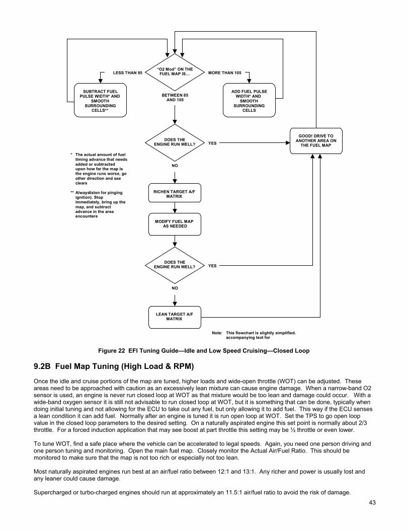
43
GOOD! DRIVE TOANOTHER AREA ON
THE FUEL MAP
“O2 Mod” ON THEFUEL MAP IS…LESS THAN 85 MORE THAN 105
SUBTRACT FUELPULSE WIDTH* AND
SMOOTHSURROUNDING
CELLS**
RICHEN TARGET A/FMATRIX
DOES THEENGINE RUN WELL? YES
BETWEEN 85AND 105
NO
MODIFY FUEL MAPAS NEEDED
DOES THEENGINE RUN WELL? YES
NO
ADD FUEL PULSEWIDTH* AND
SMOOTHSURROUNDING
CELLS
LEAN TARGET A/FMATRIX
* The actual amount of fueltiming advance that needsadded or subtractedupon how far the map isthe engine runs worse, goother direction and seeclears
** Alwayslisten for pingingignition). Stopimmediately, bring up themap, and subtractadvance in the areaencountere
Note: This flowchart is slightly simplified.accompanying text for
Figure 22 EFI Tuning Guide—Idle and Low Speed Cruising—Closed Loop
9.2B Fuel Map Tuning (High Load & RPM)
Once the idle and cruise portions of the map are tuned, higher loads and wide-open throttle (WOT) can be adjusted. Theseareas need to be approached with caution as an excessively lean mixture can cause engine damage. When a narrow-band O2sensor is used, an engine is never run closed loop at WOT as that mixture would be too lean and damage could occur. With awide-band oxygen sensor it is still not advisable to run closed loop at WOT, but it is something that can be done, typically whendoing initial tuning and not allowing for the ECU to take out any fuel, but only allowing it to add fuel. This way if the ECU sensesa lean condition it can add fuel. Normally after an engine is tuned it is run open loop at WOT. Set the TPS to go open loopvalue in the closed loop parameters to the desired setting. On a naturally aspirated engine this set point is normally about 2/3throttle. For a forced induction application that may see boost at part throttle this setting may be ½ throttle or even lower.
To tune WOT, find a safe place where the vehicle can be accelerated to legal speeds. Again, you need one person driving andone person tuning and monitoring. Open the main fuel map. Closely monitor the Actual Air/Fuel Ratio. This should bemonitored to make sure that the map is not too rich or especially not too lean.
Most naturally aspirated engines run best at an air/fuel ratio between 12:1 and 13:1. Any richer and power is usually lost andany leaner could cause damage.
Supercharged or turbo-charged engines should run at approximately an 11.5:1 air/fuel ratio to avoid the risk of damage.

4444
When running at WOT for the first time closely monitor the A/F ratio. If it is too lean or rich abort WOT and lower the map if it istoo rich or add fuel if it is too lean at the WOT area.
It is a good idea to perform datalogs when doing WOT tuning. The datalog can be reviewed afterwards and closely looked at tosee exactly what the RPM, MAP, and A/F ratio was at each point so that the fuel map can be accurately modified. See Chapter12 on operating the datalogger.
Figure 23 Fuel Map Showing Proper Wide-Open Throttle Air/Fuel Ratio
NOTE: You will know you are open loop when the Closed Loop Compensation is fixed on 100.
After you get the base fuel map very close, the engine should run fairly well if all the other parameters from the base map arereasonably close for you application. Getting the base map very close is the most important part of tuning EFI.
If it is not close in areas, you will not be able to compensate for the problems it will cause. Do not proceed to the next sectionuntil you are sure the base map is correct. The only performance that may not be close is cold start performance. This will becovered in the next section. Once the base map is tuned, NEVER modify it to compensate for poor cold engineoperation.

45
GOOD! MAKEANOTHER RUN TODOUBLE-CHECK
TUNING
WATCH THEA/F RATIO
ON FUEL MAPLEANER THAN 13.0 RICHER THAN 12.0
STOP IMMEDIATELY!ADD FUEL PULSEWIDTH IN LEAN
AREAS* ANDSMOOTH
SURROUNDINGCELLS
STOP IMMEDIATELY!BRING UP THE
SPARK MAP
DOES THEENGINE PING? ** NO
BETWEEN12.0 & 12.8
YES
SUBTRACTADVANCE* AND
SMOOTHSURROUNDING
CELLS
SUBTRACT FUELPULSE WIDTH* INRICH AREAS AND
SMOOTHSURROUNDING
CELLS**
* The actual amount of fuel ortiming advance that needs to beadded or subtracted dependsupon how far the map is off. Ifthe engine runs worse, go theother direction and see if itclears up.
** Alwayslisten for pinging (pre-ignition). Stop drivingimmediately, bring up the sparkmap, and subtract ignitionadvance in the area pinging isencountered.
Note: This flowchart is slightly simplified. Seeaccompanying text for details.
Figure 24 EFI Tuning Guide—Wide-Open Throttle—Open
CONGRATULATIONS! You now have a running EFI engine! Now that the essential base fuel maptuning is done, you can move onto the next section.
10.0 REQUIRED ADDITIONAL EFI TUNING
The following section contains information on perfecting your EFI performance. Only after the base fuel map is very closelytuned when the vehicle is warmed up, should you proceed to the following. The first tuning section was to get the base fuel maptuned for beginning users. When performing fine tuning it is sometimes necessary to work with several different screens atonce. The following will again try to guide you through in a step-by-step method without getting too complicated.
IMPORTANT! For typical performance street engines, most of the modifier values in the base maps should be fairlyclose for most engines. However, every vehicle and engine combination will require fine tuning oncethe basic tuning is done to realize the performance EFI will deliver. The more radical your enginecombination is, the more likely more extensive changes will be required.
1. Idle Speed Adjustment - If you haven’t already changed the idle speed at which you wish the engine to run, go to “HdwrSettings” and then to “Idle Air Control”. On the top it asks for the desired idle based on the engine temperature. Differentengines like (and need) to idle at different speeds. Change these to the idle speeds in which you want your engine to idle.Normally, the highest idle speed will be when the engine is coldest and it will decrease as it warms up. The difference isusually 200-300 rpm. Factors that affect the speed you want are the cam size (bigger cams usually need to idle higher), thetorque converter (converters with low stall speeds need to idle lower so the vehicle doesn’t “pull” against the brakes), andwhat the customer wants.

4646
NOTE: In the idle air control motor, there is simply a valve that lets extra air into an engine. It is used to raise the idle when anengine is cold and to maintain a desired rpm when a vehicle with an automatic transmission is placed in gear. You mustset the throttle plates to provide the majority of the airflow at idle to an engine. The IAC just supplements this. If youridle is higher than you program it to be, you have to close the throttle plates. The IAC can not take out air once it is inthe closed position. The position of the IAC is shown on the data monitor. “10” is closed and “200” is the maximumopening position. Conversely, if the engine is idling lower than you program, and the IAC is at “200”, then you need toopen up the throttle plates more. The throttle plates must be adjusted properly. This is critical for proper EFI function.
NOTE: With EFI, you should not and do not want to move the gas pedal to start the engine if all of the parameters are adjustedproperly.
2. Acceleration Enrichment - The next area to be addressed is acceleration compensation. This will be tuned at this timewhen the engine is at operating temperature. The accelerator pump on a carburetor performs the same function. To get tothis screen click “Fuel”, and then “Acceleration Enrichment”.
There are two inputs that cause the ECU to add extra fuel when the engine rpm is increased. They are: 1) When the throttle is moved which is sensed by the throttle position sensor (TPS). 2) When the load on the engine changes which is sensed by the Manifold Pressure (MAP) Sensor.
TIP: Again, the starting values on the base fuel maps should be fairly close to most applications, so you shouldn’t need to makeextremely large changes unless you have an unusual combination.
Figure 25 Acceleration Enrichment
A. Pulse Width—Rate of Change of TPS (mSec) – First, we will adjust acceleration enrichment based on the throttleposition sensor. The top of the chart that you see says “Pulse Width –Rate of change of TPS (mSec)”. It has 16 cellsthat go from left to right. What these cells do is add extra fuel when the TPS moves. The faster it moves, the more tothe right it looks for a value. Conversely, the slower it moves, the more to the left it looks for a value. The valueentered is a fuel pulse width in milliseconds. Numbers can range from 0 to 4 in these cells.
TIP: Don’t get overly worried about knowing exactly what 2 milliseconds of fuel are. Just be aware that the number can be from0 to 4 and that 4 is the most fuel you can enter when the TPS moves.
1. To tune this, slowly move the gas pedal in neutral to rev the engine up. It should be crisp and very clean. 2. If it hesitates it is either too rich or lean. The feedback from the oxygen sensor should help indicate if the engine in
going rich or lean. Monitor it. It is sometimes hard to tell which, so just change the left 3 numbers up or down inincrements of .1-.25 and see if it gets better or worse. Find the values that work best.
3. On most engines the left three values will be from 1 to 2 and the values on the right will be from 3 to 4. Thenumbers on the right are for very quick movement of the throttle, such as launching a car at the dragstrip.
NOTE: See Figure 26. This tuning provides the same function as an accelerator pump on a carburetor.
B. AE Correction vs. Coolant Temperature – The second line down says “AE correction vs. Coolant temperature”.These numbers are to modify the TPS based acceleration enrichment when the engine is colder. Just like the coolant

47
temperature modifiers, a number 110 for example adds 10% more acceleration enrichment fuel. When the enginetemperature gets up to operating level, the numbers should read 100. Usually you don’t need to make the numbersmuch more than 110 when it is cold. Tune the coolant temperature modifiers first (step 6 in this section), before youmodify these values.
C. AE Correction vs. TPS (%) – The third line down is “AE correction vs. TPS (%)”. These numbers are to modify theTPS based acceleration enrichment based on throttle position. The reason for this is that with some types of throttlebodies, such as a single blade as used on a 5.0L Ford, more air flows when the throttle is first opened than when it isalready opened further. Consequently you need to add more acceleration enrichment fuel at this point. You mightraise the TPS values where the throttle starts to open to as high as 120 for single blade throttle bodies. Throttle bodiesthat have 4 throttle plates and progressive throttle linkage may work well with 100 in all the cells. Change these valuesto find out what works best for your application.
NOTE: Next, we will adjust the acceleration enrichment based on MAP changes.
D. Rate of Change of MAP Sensor (Fuel Units – The top line, “Rate of change of MAP Sensor (Fuel Units)” is similar tothe rate of change of TPS in that the left corresponds to slow change of the MAP sensor (engine load) and the rightcorresponds to fast MAP sensor change. A slow change would be similar to slowly accelerating onto a road. A fastchange would be launching a car at the dragstrip. If you experience hesitation under load when lightly accelerating,change the left three numbers. If you experience a hesitation when you floor the throttle, change the numbers moretowards the right. Multi-port systems will usually have numbers between 10 and 40 on the left and 30 to 60 on the right.TBI systems usually require more fuel because of the distance between where the fuel is injected and the cylinder. TBIsystems may have numbers between 20 and 80 on the left to 40 to 100 on the right in some cases.
NOTE: This tuning provides the same function as a power valve on a carburetor.
Monitor the feedback from the oxygen sensor and see if it indicates a rich or lean condition. Again, it is sometimes hardto tell the difference between rich and lean hesitations, so make changes increasing and decreasing the numbers.
E. Enrichment Decay Rate (Crank Triggers) – The next line down “Enrichment Decay Rate (Crank Triggers)” is how fastthe added acceleration fuel is removed after it is added. This is based on temperature. When it is colder, you want tolet the added fuel remain slightly longer. These values will typically range from up to 20 and down to 10 when theengine is warmer.
F. AE of Map vs. Coolant Temperature (%) – The bottom line, “AE of Map vs. Coolant Temperature (%)” performs thesame function as it did for the TPS based acceleration enrichment. When the coolant temperature is lower, you canincrease the amount of MAP based acceleration enrichment that is added. Usually the most this number will be isabout 110 when the engine is cold. Again, tune the coolant temperature modifier before tuning this.
Tuning the acceleration enrichment to optimum levels requires balancing the different tuning parameters that are thereto assist with that function.

4848
GOOD! MAKEANOTHER RUN TODOUBLE-CHECKTUNING. THENPROCEED TO
MEDIUM LOADTRANSIENT TUING
DOES THE ENGINEREV SMOOTHLY?NO
RAISE LEFT 6 BOXESOF THE
“Pulse Width – Rate ofChange of TPS” TABLE
0.3 mSec*
DOES THE ENGINEREV SMOOTHLY?
YES
* Most of the time, fuel pulsewidth needs to be added to thesetables if the engine doesn’t revsmoothly. A lot of fuel needs tobe added before the enginestumbles due totoo much fuel.As always, if the symptom getsworse, try taking fuel out. Sparkadvance can also have an effect.
REV ENGINESLOWLY INNEUTRAL
NO
YES
REV ENGINE QUICKLYIN NEUTRAL
RAISE RIGHT 10BOXES OF THE
“Pulse Width – Rate ofChange of TPS” TABLE
0.3 mSec*
Note: This flowchart is slightly simplified. Seeaccompanying text for details.
Figure 26 EFI Tuning Guide—Low Load Transient—After Base Map is Fully Tuned

49
DOES THEENGINE HEISTATE OR
STUMBLE?
RAISE LEFT 6 BOXESOF THE
“Rate of Change of MAPSensor”
TABLE 10 UNITS*
YES
* Most of the time, fuel pulsewidth needs to be added to thesetables if the engine doesn’t revsmoothly. A lot of fuel needs tobe added before the enginestumbles due totoo much fuel.As always, if the symptom getsworse, try taking fuel out. Sparkadvance can also have an effect.
ACCELERATE AT AMEDIUM RATE
Note: This flowchart is slightly simplified. Seeaccompanying text for details.
GOOD! MAKEANOTHER RUN TODOUBLE-CHECKTUNING. THEN
PROCEED TO HIGHLOAD TRANSIENT
TUNING
YES
RAISE LEFT 6 BOXESOF THE
“Pulse Width – Rate ofChange of TPS”
TABLE 0.3 mSec**
DOES THEENGINE HEISTATE OR
STUMBLE?
ACCELERATE AT AMEDIUM RATE
NO
NO
** Avoid making too muchchange to the TPS enrichmenttable, as this will affect low loadtransient response. Concentratethe most on the MAPenrichment table, as this has themost affect on medium loadtransient response.
Figure 27 EFI Tuning Guide—Medium Load Transient—After Base Map is Fully Tuned
GOOD! MAKEANOTHER RUN TODOUBLE-CHECK
TUNING.
DOES THEENGINE HESITATE OR
STUMBLE?
* Most of the time, fuel pulsewidth needs to be added to thesetables if the engine doesn’t revsmoothly. A lot of fuel needs tobe added before the enginestumbles due totoo much fuel.As always, if the symptom getsworse, try taking fuel out. Sparkadvance can also have an effect.
YES
NO
FLOOR GAS QUICKLY(DRAG RACE LAUNCH)
RAISE RIGHT 10BOXES OF THE
“Rate of Change of MAPSensor”
TABLE 10 UNITS*
Note: This flowchart is slightly simplified. Seeaccompanying text for details.
Figure 28 EFI Tuning Guide—High Load Transient—After Base Map is Fully Tuned

5050
3. Spark Advance - The next area that can be reviewed is the spark advance map. The base spark maps provided shouldprovide a good performing baseline but are conservatively low for some applications and may need less for others.Optimizing timing is very important for best idle, peak safe power, and best driveability. Most people do not understand thebenefits of having computer-controlled timing. With mechanical advance you are limited to the advance curve of thedistributor. You can not change the initial advance without changing the total (unless the distributor is modified). With atiming map, you can put any advance at any engine load and RPM point. If you are familiar with the timing your engine willprobably like, change the table now. If you are not, as are most people, then make small changes to each area that you areworking on. The spark map follows the same graphical areas as the fuel map (Figure 11).
Figure 29 Spark Map
Keep in mind that stock engines with mechanical advance also have vacuum advance. The vacuum advance could addabout an extra 8-15°of timing when the engine is not under load. This increases the response and driveability of the vehicle.The timing at WOT and full load at 2500 rpm is different than what performs best at cruise and light load and 2500 rpm.
The timing an engine needs at idle varies widely depending on its specifications. Typically, the bigger the cam, the moreadvance the engine needs for the best idle. It is not uncommon that an engine with a big cam likes 25-32° of timing at idle.Stock engines may only like 4-12° at idle. Initial timing for supercharged engines must be at least 16-18° for mildcamshafts with an advertised duration around 270-290°. A camshaft with more duration will require more initial advance.Some aggressive camshaft profiles may require as much as 24-28° initial timing. Running less initial timing with asupercharger may cause excess heating, glowing headers at idle, and possible stumble when accelerating.
Timing at cruise at rpm’s between 2000 and 3000 may run between 25 and 40° and cruising above 3000 may prefer timingfrom 35-50 degrees. See what your engine likes.
At wide-open throttle, timing requirements also vary. An engine that needs a lot of timing to run best is just a sign that it hasinefficient combustion. Typically the bigger the bore, the more timing an engine may need. The better the combustionchamber and piston dome design, the less timing it needs. Most typical small blocks need between 32 and 36° for best safepower. Typical big blocks like between 34 and 40° for best safe power. The max advance should usually be in by about3000 rpm. There are sometimes power gains to add 1-2° more at high rpm with some engines. Also make sure you listenfor engine knock, especially in the peak torque area when you are changing timing.
If you drag race, sometimes putting in more timing in the map area where you stage and launch will help 60 foot times.
Usually, there is little to be gained with a few extra degrees of timing at WOT, so be somewhat conservative or you maydamage your engine.
A knock sensor is not designed so that you can run a lot of timing and let the knock sensor “pull it back to the best timing”.

51
All that will happen is that it will pull a lot of timing out and the engine will run worse than if you had the correct, safeadvance curve. Do not rely on it for performance. In applications such a towing, they are good to have if you get a bad tankof fuel and are driving in mountainous conditions.
4. Idle Fine Tuning - The next area that will be addressed is fine tuning the idle. Getting a very smooth idle is sometimes oneof the most difficult things. The following tips should be helpful:
A. One of the best features of the Commander 950 PRO for stabilizing idle is called “Idle Spark Control”. This is only usedif you have computer-controlled timing. Idle spark control is a feature in the ECU that will quickly raise and lower theignition timing automatically to stabilize the idle. If the idle moves higher than desired, the ECU will pull some advanceout to bring it down. If it goes lower than desired, it will raise the ignition timing.
1. To enable this feature, first go to the data monitor and turn the key on. 2. Note the position of the TPS and enter it here___________. 3. Next, go to “Hdwr Settings” and “Engine Parameters”. It asks for the Maximum TPS for idle under the Throttle
Sensor Settings. 4. Take your idle TPS value and ADD 5 to that value. For example if your idle TPS is 30, you would add 5 for a total
of 35. 5. Enter this value as the Maximum TPS for Idle. If this value is not more than 3-4 more than the real idle TPS
position, the idle spark control will not be activated.6. Next, go to “Spark” and “Idle Spark Control” and mouse click on the “Enable Idle Spark Control”. This will activate
this feature. The idle spark “P” and “D” terms relate to how fast the ECU changes the timing. These values aregood for the vast majority of cases, so don’t change them.
7. Next, start the engine. Look in the upper left corner of the fuel map. One of the features there says “Idle SparkActive”. When it is active, it will be highlighted in red. This should occur at idle now. You can look at the sparkadvance on the data monitor and see that the spark is changing quickly in small increments.
B. The next thing that greatly contributes to a smooth idle is having a fuel and spark map that is smooth in the area thatthe engine idles. Note the map (Figure 29) before, the timing at idle is flat. The spark map (Figure 30) below showspoor mapping at idle. If the engine was to idle at 850 rpm at 44 kPa, the timing could be jumping between 11, 19, and27 between the speeds of 400 to 1000 rpm. This causes the timing to fluctuate and will make the engine surge. Thearea at which an engine idles should have a relatively flat timing area. It is fine to add advance as the rpm increases,but when an engine is idling, the timing should not vary due to the map.
A similar rule applies to the fuel map. When the engine is idling, look at the data monitor at the Injector Pulsewidth (InjPW). It should not be changing much more than .1 - .2 milliseconds when the engine is idling. If it is, and the engineidle is not smooth, then the fuel map is probably not smooth enough. Try to smooth it so the pulsewidth does notfluctuate much. The following fuel graph (Figure 31) shows poor tuning at idle, which will cause the engine to surge.

5252
Figure 30 Poor Spark Map at Idle
Figure 31 Poor Fuel Map at Idle and Cruise
C. As was mentioned before, another key for best idle is to adjust the throttle plates so the idle air control motor is notopen much or at all when the engine is hot and in neutral. To do this, look at the data monitor and the IAC Position. Itshould read 10-15 with the engine at the programmed desired idle. If the IAC is too far open, the desired cold idlespeed will not be maintained. If the idle speed is greater than desired, close the throttle plates.

53
D. A small tip is to set the engine to idle at a speed that is proper for the engine. If you installed a very large cam, don’texpect the engine to idle comfortably at 600 rpm.
E. Changing the air/fuel ratio the engine idles at can improve idle quality. See the Closed Loop Operation section belowfor information on changing these settings.
Figure 32
F. Sometimes in more extreme cases it is necessary to change the P, I, and D terms in the idle air control area as shownabove. Usually the “P” term is lowered if a hunting idle is a problem. Changing this term to as low as 3-5 will slow howfast the IAC motor moves. You can experiment with this value if you have a problem with the idle hunting. The D and Iterms can be changed but don’t have as significant effect and the P term.
P (Proportional Term)—The proportional term makes a change based on how far from the set point the engine is. Forexample, if the desired idle is 750, the IAC would move more if the actual engine speed was 600 than if it was at 700. Exactlyhow far the IAC moves is based on how large the “P term” is.
I (Integral Term)—The “I Term” acts to eliminate the steady state error. It is the job of the “I term” to get the engine to idle atexactly 750 rpm (or whatever the set point is) and not at 740 or 760 rpm, for example.
D (Derivative Term)—This term doesn’t look at where the engine is right now, but where it is going and when it will be in a halfof a second. For example, if the desired idle is 750 and the engine speed is 700, but it is rapidly approaching 750, the “D term”will try to close the IAC to slow the engine down and keep it from “overshooting” the set point.
Figure 33 Indicates an IAC Position of 200 Figure 34 Indicates an IAC Position of 10
NOTE: It is not recommended that the user change these values, however if desired, these can be altered to improve idlecharacteristics and reduce “hunting”.
Desired Idle – The engine idle speed will be controlled by the ECU and can be changed at different temperatures. If the engineis cold, the idle speed will need to be higher than if the engine is warm for best idle stability. These values are very specific toeach application. Stock engines can idle as low as 600 RPM and some race engines need to idle over 1300 RPM. Normally,the cold idle should be about 200-300 rpm higher than the hot idle for most engines.
IAC Parked position – This is the position of the idle air motor when the engine is starting. It is a fixed value depending on

5454
engine temperature. This is an important value to help proper startup of the engine. If it is too far closed during cranking theengine will not have enough air to start, and may struggle after it fires. If it is too far open it may have too much air. If the enginestarts and revs at a high rpm, then falls to its idle speed, the parked position may be too high. Mild small block V8 enginesusually have values between 100 and 40 from cold to hot engine temperature. High performance big block engines may needvalues from 200 to 60 from cold to hot temperatures.
Minimum IAC Position – This table allows the user to cause the IAC to “follow” the throttle position. As the throttle is opened,you want the IAC to open also. This is to keep the engine from stalling when the throttle is instantly released. The IAC will notclose lower than the throttle follower position, so you will want to set the throttle follower at zero for the idle TPS position andquickly ramp the IAC open after that.
5. Closed Loop Operation, NARROW-BAND Oxygen Sensor (WIDE-BAND functions described in Chapter 9.1B – Oneof the major benefits of EFI is the ability to run closed loop. To explain closed loop operation simply, an oxygen sensorprovides feedback to the ECU, which allows the ECU to automatically adjust the amount of fuel injected to maintain a 14.7:1air/fuel ratio. A 14.7:1 air/fuel ratio has several benefits:
A. Provides good fuel economyB. This air/fuel ratio is required for typical catalytic converters to operate efficientlyC. Provides good part throttle performanceD. Creates efficient combustion which extends the life of the engine and allows for the spark plugs to burn clean
There are several parameters that can be adjusted that relate to closed loop operation on the Commander 950 PRO. Theyare described below.
Figure 35 Closed Loop Parameters (Narrow-Band O2 Sensor)
Minimum engine temp – The minimum engine coolant temperature (F) at which an engine will go into a closed loop mode.When any engine is cold, it needs more fuel to run smoothly. It needs to get the pistons and combustion chambers up totemperature before closed loop operation can begin. Most engines can smoothly begin closed loop operation at about 110-120° F. Engines with bigger camshafts may need to delay this until about 140-150° F.
Max. TPS for Closed Loop Operation – The TPS position that an engine changes from closed to open loop. An engineneeds to operate at an air/fuel ratio richer than 14.7:1 for best and safest power. This is typically between 12.5 and 13.2 fornaturally aspirated engines. For this reason, an engine needs to run open loop when engine load increases and at WOT.The TPS value you input depends on several factors. Keep in mind the following:
1. The design of the throttle body has a big effect. Two opposite examples would be an engine with a 4 bbl progressivethrottle body and one with an 80 mm single blade throttle body. If each one were open half way, the 80 mm would flowmore air on a percentage basis due to the design of the throttle body. The 4 bbl with its progressive linkage would beflowing less air due to its design. The 80 mm would need to go open loop sooner as it will allow more air to enter (andconsequently the engine would make more power sooner) than the progressive 4 bbl.
2. This value is also adjusted based on the feel of the vehicle. If it feels better to increase or decrease this value do it.
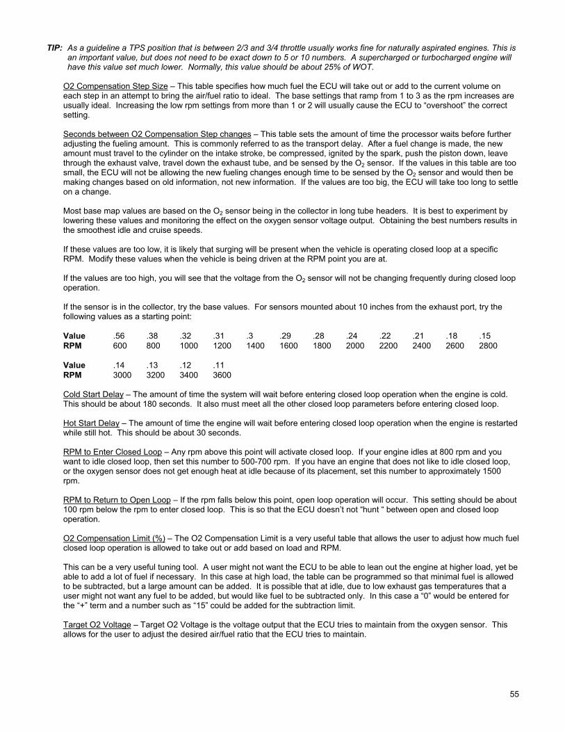
55
TIP: As a guideline a TPS position that is between 2/3 and 3/4 throttle usually works fine for naturally aspirated engines. This isan important value, but does not need to be exact down to 5 or 10 numbers. A supercharged or turbocharged engine willhave this value set much lower. Normally, this value should be about 25% of WOT.
O2 Compensation Step Size – This table specifies how much fuel the ECU will take out or add to the current volume oneach step in an attempt to bring the air/fuel ratio to ideal. The base settings that ramp from 1 to 3 as the rpm increases areusually ideal. Increasing the low rpm settings from more than 1 or 2 will usually cause the ECU to “overshoot” the correctsetting.
Seconds between O2 Compensation Step changes – This table sets the amount of time the processor waits before furtheradjusting the fueling amount. This is commonly referred to as the transport delay. After a fuel change is made, the newamount must travel to the cylinder on the intake stroke, be compressed, ignited by the spark, push the piston down, leave through the exhaust valve, travel down the exhaust tube, and be sensed by the O2 sensor. If the values in this table are toosmall, the ECU will not be allowing the new fueling changes enough time to be sensed by the O2 sensor and would then bemaking changes based on old information, not new information. If the values are too big, the ECU will take too long to settleon a change.
Most base map values are based on the O2 sensor being in the collector in long tube headers. It is best to experiment bylowering these values and monitoring the effect on the oxygen sensor voltage output. Obtaining the best numbers results inthe smoothest idle and cruise speeds.
If these values are too low, it is likely that surging will be present when the vehicle is operating closed loop at a specificRPM. Modify these values when the vehicle is being driven at the RPM point you are at.
If the values are too high, you will see that the voltage from the O2 sensor will not be changing frequently during closed loopoperation.
If the sensor is in the collector, try the base values. For sensors mounted about 10 inches from the exhaust port, try thefollowing values as a starting point:
Value .56 .38 .32 .31 .3 .29 .28 .24 .22 .21 .18 .15RPM 600 800 1000 1200 1400 1600 1800 2000 2200 2400 2600 2800
Value .14 .13 .12 .11RPM 3000 3200 3400 3600
Cold Start Delay – The amount of time the system will wait before entering closed loop operation when the engine is cold.This should be about 180 seconds. It also must meet all the other closed loop parameters before entering closed loop.
Hot Start Delay – The amount of time the engine will wait before entering closed loop operation when the engine is restartedwhile still hot. This should be about 30 seconds.
RPM to Enter Closed Loop – Any rpm above this point will activate closed loop. If your engine idles at 800 rpm and youwant to idle closed loop, then set this number to 500-700 rpm. If you have an engine that does not like to idle closed loop,or the oxygen sensor does not get enough heat at idle because of its placement, set this number to approximately 1500rpm.
RPM to Return to Open Loop – If the rpm falls below this point, open loop operation will occur. This setting should be about100 rpm below the rpm to enter closed loop. This is so that the ECU doesn’t not “hunt “ between open and closed loopoperation.
O2 Compensation Limit (%) – The O2 Compensation Limit is a very useful table that allows the user to adjust how much fuelclosed loop operation is allowed to take out or add based on load and RPM.
This can be a very useful tuning tool. A user might not want the ECU to be able to lean out the engine at higher load, yet beable to add a lot of fuel if necessary. In this case at high load, the table can be programmed so that minimal fuel is allowedto be subtracted, but a large amount can be added. It is possible that at idle, due to low exhaust gas temperatures that auser might not want any fuel to be added, but would like fuel to be subtracted only. In this case a “0” would be entered forthe “+” term and a number such as “15” could be added for the subtraction limit.
Target O2 Voltage – Target O2 Voltage is the voltage output that the ECU tries to maintain from the oxygen sensor. Thisallows for the user to adjust the desired air/fuel ratio that the ECU tries to maintain.

5656
When using a regular O2 sensor, which has a non-linear output, it is advised to usually use a value of .45 to .5. This willmaintain the A/F ratio at approximately a 14.7:1 air/fuel ratio. This is known as “stoiciometric” which is a chemically perfectair/fuel ratio for good economy, emissions, and driveability.
This value can be raised or lowered when a tuner gets more experienced to have some beneficial affects. If a larger cam isused that requires a richer air/fuel mixture to idle smoothly, the O2 trigger voltage can be raised to a value between .5 and.65. This will cause the engine to run at an air/fuel ratio richer than 14.7:1 which is needed with larger cams sometimes.Other areas such as moderate load or even cruise can be changed to make the engine run smoother. Just remember that anarrow-band oxygen sensor does not have as good of control at voltages outside of .45-.5 volts.
6. Cold Start Tuning - The first area that will likely need tuning will be cold-start enrichment. The base maps should be fairlyclose for mild performance engines. Engines with large camshafts may need large increases in this area however. Thereare two areas that are very important and need to be tuned in conjunction with each other. They are the coolanttemperature enrichment and the afterstart enrichment. We will first explain and tune the coolant temperature enrichment.It is found under “Fuel” and “Modifiers”.
The coolant temperature enrichment is extra fuel that is added to the engine as it warms up to operating temperature. Itperforms the same function as a choke on a carburetor. The lower the coolant temp, the more fuel it will need.
Figure 36 Air and Coolant Temperature Modifier Table
Figure 36 shows an example of the coolant temperature enrichment table. With the Commander 950 PRO, you enter anumber that multiplies whatever fuel value you are using from the base fuel map (based on the RPM and load of theengine). This number needs to be larger, the colder the engine is. It is very simple how it works so don’t try toovercomplicate it. If you enter a number such as 120, then the base fuel map will be increased by 20%. If the number is105 the base fuel map is increased by 5%. If you enter 100, the fuel map is not changed. 100 is used when the engine iswarm enough that it does not need any extra fuel enrichment. You can put in a number such as 90, and this will TAKE OUT10% of the fuel from the base fuel map. This is not usually needed but can be used in some instances.
Most moderate performance engines need values of about 120-125 when the temperature is about 50° F. This number willincrease to about 135 at 10° F. Engines with big camshafts may need this value to be closer to 130 at 50° F and closer to140 at 10° F. These numbers should ramp down to 100 by about 120°-150° F.
You can see the current value of the coolant modifier as the engine warms up on the data monitor. You can watch it rampdown and see and hear how the car is running.
The after-start enrichment, which heavily affects how the car runs for a few seconds after the car is started, is tuned afterthe Coolant Temperature Enrichment is tuned.
If the vehicle is to be driven or started in cold weather this tuning will have to be performed in cold weather for bestperformance. In other words, you can tune the coolant temperature and afterstart modifiers in the summer, but they mayhave to be tuned further when the weather gets colder.

57
Figure 37 Fuel Map Showing Coolant Mod and Afterstart Mod After Engine Start
To tune the Coolant Temperature Enrichment, make sure the vehicle sits overnight to completely cool down. Start the vehicle.If it stalls, start it again. Try to keep it running for a few seconds with the gas pedal. If you can’t at all, go to the Coolanttemperature enrichment. With the key on and the engine not running, see what cell is highlighted in the coolant temperatureenrichment table. This is the value that is being used at the engine temperature you are at. Increase this cell and the cell to theleft of it and the right by 5 (for example 120 to 125). Start the car again. Try to modulate the gas to keep it running. If it doesn’tincrease the coolant temperature enrichment 5 more, start the car again. After this much change, it should be able to idle. If itdoesn’t, you may need to now alter the after-start enrichment.
If the car was able to idle without adding any more coolant temperature enrichment or was ok after adding 5-10% more, let theengine continue to warm up at idle. You can watch the coolant temperature enrichment on the data monitor. If at any timeduring the warm up period the engine seems too lean or rich, go to the Coolant Temperature Enrichment table and increase thepercentage at the temperature that the engine is at (again, you will see that cell highlighted in red). Change this area while theengine is running until the engine sounds better.
Narrow-Band Oxygen SensorIf the oxygen sensor is correctly placed relatively close to the cylinder head, you should see a voltage output of approximately .7-.9 volts when the coolant temperature enrichment is close to ideal after the oxygen sensor is up to proper operating temperatureand when the engine is still cold. If the car is running rough and the oxygen voltage is below this, you need to raise the coolanttemperature modifier at the particular coolant temperature the engine is at.
Wide-Band Oxygen SensorMost engines run well when cold with an air/fuel ratio between 12.7 and 13.5. Experiment to find which is best. The leaner youcan tune an engine to run while still have smooth operation, the better the fuel economy will be.

5858
GOOD! START THEENGINE THE NEXT
MORNING TORECHECK
SETTINGS**
DOES THE ENGINESTALL IN THE FIRST 2
SECONDS?YES
INCREASEAFTERSTART
ENRICHMENT 5% ATTHAT ENGINE TEMP*
ADD 5% MORECOOLANT TEMPENRICHMENT AT
THAT ENGINE TEMP*
DOES THE ENGINESTALL DURING
WARMUP?
NO
NO
* The actual amount of fuel thatneeds to be added depends uponhow far the settings are off.
** The settings may need finetuning as varying cold startconditions change (summer towinter, etc.)
START THE ENGINE
YES
DOES THE ENGINERUN ROUGHLY DURING
WARMUP?
NO
ADD 2% MORECOOLANT TEMPENRICHMENT AT
THAT ENGINE TEMP*
YESDOES THE ENGINECONTINUE TO RUN
ROUGHLY?
NO
YES
Note: This flowchart is slightly simplified. Seeaccompanying text for details.
Figure 38 EFI Tuning Guide—Cold Start—After Base Map is Tuned Hot
Afterstart Enrichment - Afterstart enrichment is fuel added immediately after the vehicle starts. It is then taken out veryquickly. How much and how quickly is adjustable with tables in the software. Even after the coolant temperature enrichment isproperly set, afterstart enrichment provides and engine with more fuel for a short time that is necessary for best operation. Likecoolant temperature enrichment, how much afterstart enrichment needed has a lot to do with the camshaft in the engine.Efficient, high vacuum engines with small cams need less afterstart enrichment than engines with large cams and low vacuum atidle.
Figure 39 Startup Enrichment

59
Afterstart enrichment is found in “Fuel” and then “Startup Enrichment”. There are three parts of this area that deal specificallywith afterstart enrichment. They are:
Afterstart Enrichment – Works the same way as the coolant temperature enrichment. If the number is 140, then 40%more fuel is added from the base fuel map when the vehicle starts. Unlike the coolant temperature enrichment thatdecreases as the engine temperature increases, afterstart enrichment decreases based on the “Afterstart Decay Rate”,defined below.
This is by far the most critical value of the three mentioned here. For moderate performance engines, 130-140 is agood value for temperatures between 40 and 60° F. The values will need to be increased as the temperature getscolder and decreased as the temperature gets warmer.
Afterstart Holdoff – Number of engine revolutions that the engine turns before adding the afterstart enrichment. Thisnumber is usually between 15 and 5. It allows the engine a few revolutions before adding the fuel.
Afterstart Decay Rate – How quickly the Afterstart Enrichment decreases. The number entered is how manyrevolutions of the engine between each 1% decrease of the afterstart enrichment. A higher number slows the decreaseand a lower number increases the decay. This number usually needs to be between about 20 and 5.
You can watch how much afterstart enrichment is added on the data monitor screen when the engine starts and is running. Youcan also view the coolant temperature enrichment there. When you do a cold start watch these numbers and listen and feel howthe engine is running. Make modifications to them until the engine starts and will not stall or run roughly.
NOTE: Since the base fuel map was already tuned when the engine was warm, DO NOT change it to help cold startperformance. If you do, you will ruin the hot performance. Change the parameters above only to help cold startperformance.
11.0 ALPHA-N TUNING
NOTE: Alpha-N is never used for supercharged or turbocharged engines.
The information in this section translates into some basic fundamentals for Alpha-N systems:
1) Only use Alpha-N if you absolutely have to. This means that your engine has roughly less than 8.5” (Hg) of vacuum at idle,although you can successfully tune in speed density mode with less vacuum than this.
2) On street driven cars, select a camshaft that will provide more than approximately 8.5” (Hg) of vacuum. Ideally at least 12”(Hg). This will make tuning easier, but once again, engines with very low vacuum can be successfully tuned in speeddensity mode when tuned properly.
3) If you must use Alpha-N on a street car, use a throttle body that delivers a linear increase in airflow.4) Alpha-N can be used on drag-only cars successfully no matter what the camshaft or throttle body design is.
Alpha-N Overview – Speed density and Alpha-N are the two methods that the Commander 950 PRO can use to determinefueling requirements. Most all aftermarket EFI systems allow the user to use one of these methods. To determine how muchfuel to inject, the ECU uses two base inputs. For speed density it uses the RPM and manifold pressure (from the MAP sensor).Alpha-N also uses RPM but instead of manifold pressure, it uses the throttle position sensor (TPS) to calculate fuel pulsewidth.You should always use speed density with engines running a blower or a turbo as they need the MAP sensor to sense boost andadd the proper and safe amount of fuel.
Alpha-N should only be used when there is not enough manifold vacuum at idle which is typical of race engines with camshaftswith large duration and overlap. There are no set-in-stone rules when to run Alpha-N. The following reviews when you mostlikely need to use it and the problems and limitations of Alpha-N.
The advantage of speed density is that it truly senses changes in engine load by monitoring manifold pressure (or vacuum) thatdirectly relates to fuel requirements. Alpha-N can not truly sense engine load, just throttle position, which in some cases can notcome close to accurately sensing large changes in engine load. Why is this true? The following example will explain this:
A good example of an engine that will not work well running an Alpha-N strategy is a hot street/strip car with a single,monoblade throttle body, such a naturally aspirated 5.0L style Ford engine. A vehicle like this, especially if it is running bigdiameter throttle body, will have driveability problems running Alpha-N. When tuning an engine like this you would firstadjust the idle fuel. This would be no problem to accomplish. However, due to the design of the throttle body, a smallchange in the throttle position (just after idle) creates a large change in airflow into the engine. The area that you are on thefuel map may only change a little, but because of the large increase in airflow, you need a large increase in fuel. Thismakes the fuel map very uneven. This causes poor driveability that is hard or impossible to resolve with mapping. If thissame engine were mapped using speed density operation, this large change in airflow would create a large change in theposition of the fuel map. This would allow for the map to be smooth creating a much better driveability.

6060
It is always best to run a throttle body design that has the most linear increase in airflow possible. A good example would be a 4bbl style with a progressive linkage.
Another example of a deficiency of Alpha-N would be a vehicle with an automatic transmission. With speed density you wouldtune the fuel map when the car was in neutral. You would then put it into gear. This would change the load on the engine andwould change the point on the map you are tuning, allow proper fuel in neutral and in gear. With Alpha-N, you would be at thesame point in the map whether in neutral or in gear. The result would be a fuel map that is a compromise between these twopoints.
You likely need to run Alpha-N when the manifold pressure as measured with the MAP sensor is greater than about 70 kPa.This is approximately 8.5 inches of vacuum. The reason for this is really the same as the problem described above with runningspeed density. You will have large changes in the fuel map that will hurt driveability. For example, if an engine idles at 75 kPa,you can tune it to idle fine at that rpm. However, 2500 rpm and 75 kPa usually mean that the engine is under load and needs alot more fuel than it did at idle. Therefore, the map would have big “valley” below about 1500 rpm what would make it hard totransition from idle to light load and higher load.
Alpha-N is typically used on drag-only cars. Even if they have a throttle body design that is not ideal such as the Ford stylementioned above, it is not usually a problem on drag cars because they mostly need to operate at idle and wide-open throttle(WOT). Other than the burnout and driving through the pits, they only see these two extremes. These two areas can bemapped very successfully with Alpha-N. Cars with throttle stops also are ok because the throttle stop area of the map can beproperly mapped.
There seems to be some misinformation about Alpha-N and closed loop operation. You can run a system Alpha-N and runclosed loop. The two are completely non-related, except for the fact that most Alpha-N systems are used on all-out racecars,which run open loop all the time typically. If you have a street car that runs Alpha-N, you can run closed loop as long as theengine runs smoothly at a 14.7:1 air/fuel ratio at idle and/or cruise.
Tuning Alpha-N – Tuning Alpha-N is basically the same as tuning a speed density system. All of the other tables (start-upenrichment, ignition timing, coolant and air temp modifiers, IAC, & O2) work the same whether you are running Alpha-N or SpeedDensity. If you had both fuel maps tuned precisely, then these tables would be practically the same.
The only difference would be the fuel map. They will be very different. The WOT fuel curve will be exactly the same. That isbecause with both speed density and Alpha-N, you will be using the fuel values from the top row. However, depending on theTPS position, you may be reading values a few lines down from the top using Alpha-N.

61
Figure 40 Typical Alpha-N Fuel Map
Mapping is the same as speed density from the aspect that the area on the base fuel map that you are obtaining fuel map valuesfrom will be highlighted in red. Drive the vehicle at different throttle positions and engine speeds to modify the fuel map asneeded. Closed loop feedback and oxygen sensor voltage can both be used for feedback just like speed density.
Photograph courtesy of Tony Thacker

6262
12.0 DATA LOGGER
Figure 41 – Datalogger
The Commander 950 Pro software both and internal and PC datalogger. The internal datalogger does not require the laptopcomputer to be hooked up. The internal datalogger can be used for logging runs at the dragstrip or for other types of racingwhere you can not or do not have a laptop in the vehicle. The data is then downloaded later for review in the laptop. The PCdatalogger is used when a large amount of data needs to be stored and it is feasible to have a laptop connected to the ECU.
12.1 Starting the PC DataloggerTo start the PC data logger, first select “File”, and “Log Data”, after the datalogger is opened. This will bring up the windowbelow (Figure 42) asking you to specify a filename. Select the directory you want to save it under and enter a filename.
Figure 42

63
After you enter a filename hit “OK”. The “Trigger” screen below (Figure 43) will appear.
Figure 43
The trigger screen (Figure 43) allows you to start the data logger immediately or wait for a trigger point. The trigger point is aselectable input such as RPM, TPS, and more. You can input a value for any of these. When the system reaches this value itwill automatically start. The example above would wait for an engine rpm greater than 3000 to start taking data. After selectingthe parameters wanted, hit the “Start Datalog” button. Once the “Start Datalog” button is pressed, the PC starts monitoring thedata stream from the ECU and is looking for the start conditions to be met. This is indicated above the start button with “waitingfor trigger”. If the ECU is not connected or powered up, the datalog will abort (as indicated by printing “Datalog Aborted” abovethe start button). If the datalog is aborted, the start button can be pressed again to restart the datalog session. Once theconditions are met, the PC will start logging data as fast as it can. The sampling speed will depend on the speed of the PC, butis typically 10-20 samples per second. At the end of the session the user can press “Stop”, or simply turn off the vehicle.
Once the session is stopped, pressing the start button will restart the session but all prior data will be LOST. This can help if adatalog is started prematurely and you want to restart it.
NOTE: If you select “Start now” the data logger will automatically start when the “Start Datalog” button is pressed.
If a datalogging session is stopped from the stop button, a “Continue” button pops up. Pressing this button will continue thedatalogging session without starting over. This could be useful when trying to log data while driving in traffic, but you have nodesire to log data at the stoplights.
12.2 Starting the Internal DataloggerThe internal datalogger is started by one of two input lines. These lines can be used for multiple purposes and must beprogrammed to activate the internal datalogger in the Input/Output window covered in Chapter 13 Input/Output. Depending onwhich line is selected, they are either brought to ground or to battery voltage, which triggers the datalogger to start. Forexample, the user could select the Park/Neutral input to start the datalogger. Instead of connecting this wire to the neutral safetyswitch, it could be connected to a pushbutton on the wheel or on the dash. As the driver stages, he could push the button toactivate the datalogger and start storing data. Once the datalogger has started, it will continue to log data until the ECU is shutdown, the memory is full, or the user asks the PC to extract the data from the ECU memory. Depending on how many variables are logged and at what rate they are logged will determine how much time it takes to fill theavailable memory. At the fastest rate and the maximum dataset size, there is enough memory for 24 seconds of data – morethan enough for a typical drag race. At the slowest rate and the smallest dataset size, the datalogger will run for two and a halfminutes before it runs out of memory. The datalogger speed and dataset sizes are selectable from the Input/Output screencovered in Chapter 13.12.3 Datalogger SpeedThe selection here determines how fast the internal datalogger will sample. Three sample rates are available: 20 times persecond, 10 times per second, and 5 times per second. Each of the sensors in the chosen dataset will be sampled at this rateand saved to memory for later retrieval. Naturally, there is a limited amount of memory and choosing a faster data sample speedwill use up the available memory faster.

6464
12.4 Dataset SizeThis selection will determine how many of the sensors the datalogger will store. There are three set sizes, which can beselected – small, medium, and large. The sensors that are sample for each set size include:Small: TPS
MAPEngine RPMInjector Pulse WidthO2 sensor voltageClosed Loop Modifier valueAnalog input 1 (pin B6, 0 – 5V input)
Medium: All the previous sensors plus:Analog input 2 (pin B12, 0 – 5v input)Ignition timingEngine coolant temperature
Large: All the previous sensors plus:Battery VoltageAir temperatureAir temperature modifier
Obviously, there is a limited amount of memory available and choosing a larger dataset size will fill the available memory fasterthan a smaller dataset. However, even with a large dataset size and the fastest sample rate (20 times per second) there is stillover 20 seconds of sample time available; more than enough for a typical drag race. With the smallest dataset size and slowestsample rate (5 times per second), there is enough memory for about two and a half minutes worth of data.
12.5 Downloading Logged Data to the PC. Before the data can be viewed, the data must be downloaded from the internal datalogger to the PC. With the ECU powered upand the communications cable attached between the PC and the ECU, go to the datalogger and select “Xfer Data from ECU toFile” from the File menu selection. You will need to enter a filename when asked. This will be the filename the data will besaved to. The data extraction will take a couple of minutes. Once the data has been extracted from the ECU, the ECU datacounter is reset and another internal datalogging session can occur. When you are ready to view the data, follow the instructionsin the next section.
12.6 Viewing DataAfter data is saved you can open and review it. Go to “File” and “Open Data File” in the data logger. Select the directory andfilename that you want to open. The following screen will then appear. You can review each point of the data. The followingfeatures are available in the data logger (Figure 44).
Select Inputs to View – You can select which inputs to view and not view by simply clicking once on the input name on thebottom of the screen. If the data is not shown the input name will be in black. If it is shown it will be a color other than black.The color of the name will correspond to the color of the data on the chart. Up to six data points can be graphed at once.
To View a Data Point – To view the values for any point on the graph, move the mouse pointer to a data line at the point youwant to view. When in the correct area, the pointer will turn to a “hand”. Click the left mouse button. This will move to that point.To move to a different value you can use the arrow keys to move left and right.
Zoom - To zoom in on data, move the mouse to the left portion you would like to zoom to, make sure it the mouse pointer is an“arrow”, and hold the left mouse button down. Sweep the mouse to the right to the position you want to zoom to and release themouse button. You will automatically zoom in. Zoom out by clicking the “Undo Zoom” button.

65
Figure 44
TIP: If more than 5,000 data points are taken, the software will automatically split them up into separate files. 5,000 data pointsamount to 5-8 minutes depending on the computer.
TIP: For example, if you take 15 minutes of data and name the data file TEST, you will have 3 separate files automaticallysaved. When you go to load a file you will see three file names. They will be TEST, TEST01, and TEST02. The softwareautomatically adds a 01, 02, etc. at the end of extra files.
13.0 INPUT/OUTPUTS13.1 Input/OutputThese parameters determine how some of the input and output lines are controlled. Two inputs and two outputs can beprogrammed by the user to perform different functions. Also, the internal datalogger speed and data set size is programmedhere.
Figure 45 – Input/Output Screen

6666
13.1.1 Input 1 (12V activation – B8)This input is positioned in location B8 of the main ECU connector. This line is activated by a 12V input. This input can beselected for three uses. The first use is as an indication of whether or not the A/C was activated and therefore if the idle speedneeds to be increased. It can be used to start the internal datalogger, or it can be used to activate a timing retard. If the retardoption is selected, you will need to program the amount of retard desired. If it is used for the datalogger, it is best if a momentaryswitch is used, although the datalogger can be trigger by a 12v input that is left on.
13.1.2 Input 2 (GND activation – B10)This input is positioned in location B10 of the main ECU connector. This line is activated by a Ground input.
This input can be selected for three uses. The first use is as an indication of when the vehicle is shifted out of park or neutral andinto drive or reverse and therefore needing a little “kick” of the IAC to overcome the initial load increase. It can be used to startthe internal datalogger, or it can be used to activate a timing retard. If the retard option is selected, you will need to program theamount of retard desired. If it is used for the datalogger, it is best if a momentary switch is used, although the datalogger can betrigger by a 12v input that is left on.
Note that only one retard is available and if both inputs are selected to perform the retard function, there will not be a doubling ofthe retard amount. For example, if the retard is programmed for 5 degrees for both the B8 and B10 lines, activating either of thelines will give 5 degrees of retard and activating both of the lines will still only give 5 degrees of retard (not 10).
13.1.3 Output 1 (D9)This output is positioned in location D9 of the main ECU connector. This line will give a ground output when activated and cansupply up to four amps of current. This output can be programmed to function as a RPM activated switch, a TPS positionswitch, or a MAP position switch. Some possible uses include a shift light or a wastegate.
13.1.4 Output 2 (C1)This output is positioned in location C1 of the main ECU connector and normally functions as a fan switch, turning the fan on atone temperature and off at another. Alternately it can be programmed to function as a RPM, TPS, or MAP position switch asdescribed above. This output supplies a ground connection when activated and can supply up to four amps of current.
13.2 Datalogger
See Datalogger Chapter 12.
Figure 46
13.3 About
13.4 NotesThis window allows the tuner to view or change notes about the current fuel map. If an ECU is attached, it will extract the notesfrom the ECU, otherwise it will show whatever notes may be in memory. These notes are also saved to disk when the data issaved.
13.5 Version
The version shows the computer software version and the firmware hardware version. The Pro software version should beversion 3.x and the firmware should be version 3.x. The firmware version is only viewed when live with the ECU.
13.6 Advanced UserThe advanced user box is used to hide several of the more advanced features in several screens. The features normally do notneed to be changed for most applications. To view these features click the advanced user box.

67
APPENDIX 1 COMPLETE SOFTWARE OVERVIEWAppendix 1 provides a description of all the software functions. It is not intended to describe how to tune an engine, but rather toprovide one section that details all the different screens that will be used.
COMMANDS
FileThe sub categories here allow the user to retrieve, send, open, save, etc. the internal settings or “maps”.
Retrieve ECU DataThis function pulls all the data out of the ECU. Each time one of the windows is opened, the PC attempts to pull the necessarydata to fill that screen, whereas this function will pull ALL the data out of the ECU. This must be done if you wish to save thesettings to disk.
Send ECU DataThis function sends a complete data set to the ECU. If the user wishes to completely change all the settings (such as going froma street map to a racing map), the saved racing map would be loaded from disk and then sent to the ECU using this feature.Note that if no map is loaded, only zero exists in the PC and all zeros will be sent to the ECU.
Force Default ValuesThis function is used when a map is loaded from an older version of the Commander 950 PRO system (software version 1.xxx)that does not have correct variables for any of the new features. This allows for these variables to be entered quickly withouthaving to manual type them in. To do this operation a laptop must be hooked up to the vehicle with the ignition “on”. Next theforce default value button is hit and the values will be updated. The values may not be optimal, but should allow for the engineto run.
Open Data from DiskTo retrieve a complete data set (or “map”) from disk, this function is selected. This would be used to open one of the many fuelmaps available from the website. It is recommended that you save your work regularly, so that if you get to a point where youfeel the vehicle is not working as well as it was just a few changes before, you can always go back to some previous settings thatyou saved.
Open only Fuel Data from DiskSometimes, it is desirable to change only the fuel map, but leave all the other settings the same. One situation might be whenstarting a new vehicle, the user may want to try several different fuel maps, but doesn’t want to reset or re-verify that all thehardware parameters are set for his engine. To do this, the user would first load an entire map from disk and send it to the ECU.Then, he would open only the fuel data from another map and send the new values to the ECU using the “Send ECU Data”function. If the engine still didn’t start, another fuel map could be tried by again selecting the “open only fuel data from disk” andthen “send ECU data” functions.
Open only Spark Data from DiskThis function works the same as the fuel data described above, except that only the spark data is retrieved from the disk.
Save Data to DiskUsing this function will save all the settings currently in the PC to disk. To be sure all the settings are in the PC, you should first“Retrieve ECU Data”. If you do not retrieve all the data prior to saving, you risk not having all the correct data in the PC andinstead have zeros for several data values. Saving these incorrect data values and then later retrieval and sending of thesettings to the ECU could cause many problems that could be difficult to understand or explain.
Save Fuel Map as Excel FileSometimes it is desirable to view the fuel map with a spreadsheet. This function will save the fuel map in a “comma delimited”format, which can be read by most spreadsheets, including Microsoft Excel.
Save Spark Map as Excel FileThis works the same as the previous function but saves the spark map.

6868
Print AllJust as the name implies, this function will send all the settings to the printer. The settings can then be stored in a racinglogbook, for example.
Password
Figure 47
The software package allows password protection, if so enabled. This window is used to set/reset the password and forpassword verification once set. If the password is not set, the window will come up as shown and allow the user to set the newpassword. Type the password in the text space available and press Set Password. Once the password is set, the passwordprotection can be enabled by checking the checkbox labeled “Password Protection On”. Once the password protection isenabled, the unit will need to have the password sent before any values can be viewed or changed. If you forget to send thepassword and go straight to a tuning screen, only zeros will be displayed. If new values are sent, they will not be accepted bythe ECU, until after the password is sent and verified. Once the password is verified by the ECU, normal communication willresume. DON’T FORGET YOUR PASSWORD. IF YOU FORGET IT, YOU MUST SEND THE ECU BACK TO HOLLEY TOHAVE THE PASSWORD CLEARED.
ExitUse this to exit the software.
CommUnder this heading, the user must select the serial communication port (“Comm Port”) that will be used to communicate with theECU. The software must know where to look for the ECU and supports comm ports one through four. If your computer does nothave a DB9 serial port (many newer laptops don’t), you will need to purchase a USB to DB9 serial adapter from your localcomputer store. Once the selection is made, the software will “remember” the settings the next time you use it.
FUEL These allow the user to alter the fuel specific parameters of the engine.
Main Fuel Map This is the primary table the engine uses when it is running. Each box or “cell” contains a number representing the injector pulsetime. The larger the number, the longer the injector is pulsed, and the more fuel is delivered. The cells are organized by enginespeed (RPM) and load (MAP or TPS depending on whether speed-density or Alpha-N is selected; typically, speed-density will beused). Typically, the greater the manifold pressure, the more fuel is needed. Also, the fuel requirements vary with engine speedbased on the breathing efficiency of the engine. If the ECU is attached to the PC, the cell background color will change toindicate which cell is being utilized by the ECU for its fuel calculations. This cell background color change will move around asthe engine speed and load change.
When first brought up, the cursor will be in the lower left corner of the cells. Obviously, you can use the mouse to move thecursor to different cells, but it is probably more beneficial to use the arrow keys. When using the arrow keys, the number in thecell will be highlighted so you can immediately type a new number to alter the fuel amount in that cell. You can also use the upand down arrow keys with the shift or control keys pressed to increase the cell value. After using the arrow keys to change thecell value or typing a new number, the data is not sent to the ECU until you press enter or move off that cell with the arrow keys.All other cells in the system work the same way. Pressing ctrl-R will fill all cells in the row to the right of the cell you are workingon with the same value you just entered. This can greatly speed up the process of building a map from scratch.
Another feature is the use of the “Cell action” function. If you click on one cell and click on another cell, the square they createwill be highlighted yellow and a “Cell Action” window will appear. You can now type either +, -, *, /, =, or % followed by a numberand that action will be performed. For example, if you type “*1.5”, all the highlighted cells will be multiplied by 1.5 and the newvalues will be sent to the Commander 950 PRO. If the “=” sign is used, a single number can be entered in all selected cells. Forexample “=20” would put a 20 in all selected cells.
A very useful feature that is provided in the fuel map is that if a number is entered that will cause the injectors to become static,that cell will be highlighted in red. This means that increasing this number further will not add any additional fuel to the engine.

69
Figure 48
Data Monitor Used for monitoring real-time engine parameters.
Both the Main Fuel Map and Spark Map screens have a readout of real-time engine parameters above the graph. This is anessential tool when tuning an engine. The following is an explanation of each readout:
Closed Loop Compensation – Indicates the percent modification to the base fuel injection pulse width, only when the engine isoperating closed loop. 100 would mean that no correction is occurring. 120 would mean that the computer is adding 20% morefuel to the base pulse width value. A value of 80 would mean that the computer is subtracting 20% from the base pulse width.
Closed Loop Compensation Graph – There is a small bar graph that is a graphical representation of whether the computer isadding or subtracting fuel in a closed loop mode. If the bar graph reads to the right, the computer is adding fuel because thebase pulse width is leaner than the target air fuel ratio. If the bar graph reads to the left, the computer is subtracting fuelbecause the base pulse width is rich. The far left or right of the scale indicates a fuel change of 10% at least.
Rich/Lean Indicator Light – This light includes the voltage output from the oxygen sensor in large numbers to aid in tuning.When the air/fuel ratio is leaner than 14.7:1, it will turn red. When the air/fuel ratio is richer than 14.7:1, it will turn yellow. Whenthe voltage is higher than .75V, it will turn green. This signifies a safe air/fuel ratio under load. The colors will only change whena narrow-band oxygen sensor is used. The background will not change when a wide-band sensor is used.
RPM – Indicates actual engine speed. This new software shows the engine speed to one RPM.
Spk Adv – Shows current spark advance.
IAC Position – Indicates the position of the pintle on the idle air control motor. This is a very important reading for adjusting idle.The scale reads from 0 (closed) to 200 (fully open). If the idle is too high and this value is 10, the IAC can not close further,which means that the throttle plates must be closed instead. If the idle is too low and the value is 200, the IAC is fully open andcan not add more air, which means that the throttle plates must be opened more.
O2 Trigger Voltage/Target A/F – When a narrow-band oxygen sensor is used, this Indicates the voltage level the ECU is trying tomaintain at the O2 sensor input. When a wide-band oxygen sensor is used, this indicates the air/fuel ratio the ECU is trying tomaintain.
MAP – Shows the manifold pressure: if 1 bar, will vary between 0-100, 2 bar=0-200, and 3 bar=0-300.

7070
TPS – Shows the position of the throttle position sensor.
MAT – Manifold air temperature in degrees Fahrenheit.
O2 – Shows the output voltage from the oxygen sensor. The range is 0 to 1 volt for a narrow-band oxygen sensor and 0-5 voltsfor most wide-band oxygen sensor inputs.
V Bat – Indicates battery voltage.
Coolant – Indicates the coolant temperature in degrees Fahrenheit.
MAT Mod – Indicates the modification to the base fuel pulse width based on intake air temperature. Based off of a percentageof 100%.
Clt Mod – Indicates the modification to the base fuel pulse width based on coolant temperature. Based off of a percentage of100%.
Aft Mod – Indicates the fuel afterstart modifier—percentage based.
Atm Mod – Indicates modification due to atmospheric conditions—percentage based. This modifier is now always available (oldsoftware made it available in Alpha-N mode only.)
Inj PW – Indicates fuel injector pulse width. Units are milliseconds.
Duty Cycle – Indicates the amount of time that the injectors are open, based on a percentage of available on and off time. It isimportant to make sure it is not over 85% (ideally) at wide-open throttle. This will reduce injector overheating. If it is 100 ormore, the injectors are fully open (static) and can not provide any more fuel to the engine. If you enter a value in the injectionvolume table that will drive the system to a static condition, that cell will become red. This value will have to be lowered. If morefuel is needed, the fuel pressure can be raised, or larger injectors are needed. Labels on the left indicate status of variousfunctions by changing the background color. For example, you will notice that the “Fuel Pump On” will highlight when the fuelpump is running.
Trigger Type – Indicates the ignition type selected in the engine parameters.
Fuel Graph This is a graphical representation of the fuel cell values. When properly tuned, the fuel map should be smooth. The graph modecan be used to refine the fuel values into a smoother curve. You will want to view some of the supplied fuel maps to see what afuel graph should look like once finished. Once you become familiar with engine tuning, you can often tune an engine very closeby tuning 10 to 15 points and using the fuel graph feature to fill in the rest. You can move around this map using the arrow keysand can alter values by pressing the shift or ctrl key along with the up or down arrow. Naturally, the up arrow increments thevalues and the down key decrements the values. The shift key causes the step amount to be one unit, whereas using the ctrlkey causes the changes to be made by 5 units. After making changes, the new value is not sent, until you press “Enter” or moveoff the cell using one of the arrow keys.
Figure 49
Startup EnrichmentThe following five parameters are used by the ECU during cranking and shortly after the engine actually starts.

71
Figure 50
Cranking Pulse Width – Often, the amount of fuel needed is greater when starting the car than when actually running. Thistable allows the user to define the injector pulse width during cranking and to specify different amounts based on the enginetemperature.
Afterstart Enrichment – Once an engine is started, it will require a slightly richer fuel mixture for a short period of time. Thistable allows the user to specify the amount of enrichment that the engine will receive. The values shown will be in percent withnumbers greater than 100 increasing the base fuel delivery and numbers less than 100 reducing the fuel delivery.
Afterstart Holdoff – These parameters control the number of revolutions the ECU waits before adding the afterstart fuelenrichment.
Afterstart Decay Rate – Rather than deleting the afterstart enrichment after the afterstart holdoff period all at once, the ECUallows the user to program the speed of decay. The number in each cell corresponds to the number of revolutions to allowbetween 1% fueling changes. The greater the number, the slower the afterstart enrichment will decay.
Auto Prime 7 mSec Pulse Count – (TBI only) This number is the number of fuel pulses injected, if you are trying to “prime” theengine. This occurs if you press the throttle beyond the WOT point and release it. If the ECU is correctly calibrated, this featureshould not be needed.
Acceleration Enrichment The following six groups of parameters are for adjusting fuel delivery when the engine is accelerated. This table is based uponchange in TPS position and change in MAP reading.
Figure 51 Pulse Width – Rate of change of TPS (Delta TPS) – This table sets up a pulse width of fuel to be delivered to the engine whenthe TPS changes. The faster the throttle is opened, the further to the right the ECU will go to get the pulse width value. Theactual number entered is the pulse width in milliseconds. Because of minimum on-time settings, values under 1.5 milliseconds

7272
will not inject fuel.
AE Correction vs. Coolant Temperature (%)– This allows the user to give more acceleration fuel based on the enginetemperature to compensate for fuel droplets sticking to the manifold walls or cylinder walls. The number entered is a percentagemodification to the Delta TPS. Numbers over 100, such as 110 (%), add 10 percent more fuel to the base Delta TPS number.Numbers lower than 100, such as 90 (%), reduce the base Delta TPS by 10 percent. If 100 is entered, there is no modificationdue to temperature to the base Delta TPS.
AE Correction vs. TPS (%)– This allows the user to adjust the size of the acceleration compensation, based on how far openthe throttle is. This can be very useful for large throttle bodies, where small changes off idle can give large airflow increases.Changes to the throttle after about mid-throttle give little airflow increase. This is also percentage-based with numbers lowerthan 100 subtracting a percentage from the base Delta TPS and numbers higher than 100 adding a percentage to the baseDelta TPS. The numbers below the table indicate the throttle position sensor position.
Rate of Change of MAP Sensor (Delta MAP) – A change in the manifold pressure can indicate a change in the engine loadingrequirements. The values entered are fuel units, are the same as the base fuel map (whole numbers), and are added to thebase fuel value. Decay – This is how fast to pull out the additional fuel after detecting a change in the manifold pressure. This is the number oftriggers to wait between the subtraction of 1% of enrichment.
AE of MAP vs. Coolant Temperature (%) – Colder engine temperatures may require different transitional fueling requirements.This table allows the user to tailor the synchronous fueling to the engine temperature. Numbers are percentage-based.Numbers below 100 subtract a percentage from the base Delta MAP and numbers higher than 100 add a percentage to the baseDelta MAP.
Modifiers The following three tables adjust the base fuel delivery according to various external sensors. All table entries are in percent.Numbers greater than 100 increase the fuel delivered, and values lower than 100 decrease the amount of fuel delivered.
Figure 52
Air Temperature Enrichment (%) – This table adjusts the base fuel delivery based on the air temperature. The density of airincreases one percent for every eleven degrees Fahrenheit of temperature increase. Once the engine is tuned correctly at acertain temperature, the fuel should be adjusted accordingly for all temperatures warmer and colder than the tuning airtemperature.
Coolant Temperature Enrichment (%)– This table is similar to a carburetor’s choke function. At cold engine temperatures, theengine will need more fuel, because some of the injected fuel will stick to the manifold walls or to the walls of the cylinder. Athigher engine temperatures, this table can be used to increase the amount of fuel delivered to help cool the engine down.
Additional Timing vs. Temperature (degrees)– This table allows the tuner to add or subtract ignition timing, based on thecurrent engine temperature. This could be useful to add a little timing when the engine is cold to help increase the idle or to geta little more power out of the engine when the cooler engine temperatures permit. A zero value will not change the timing at all.Values greater than zero increase the timing and values less than zero decrease the timing.
Barometric Compensation (%) – This table is available in just Alpha-N mode. It allows the user to adjust fuel delivery asaltitude changes. As shown in Figure 52, one of the cells will be highlighted that will correspond to the barometric pressurebeing used. A value of 100 in this cell will not change the programmed fuel delivery amount. A value greater than 100 willincrease the amount of fuel to be delivered and an amount less than 100 will decrease the amount of fuel delivered. If thisfeature is to be used, do all the fuel tuning at a constant altitude. Once the fuel map is tuned, adjust the barometric

73
compensation values to adjust for altitude requirements. In order for this to work properly, the map sensor must be open toatmospheric air.
SPARK These are all the parameters for adjusting the spark delivery to the engine.
Main Spark MapThis is the primary spark map used by the ECU to determine where to make the spark. The table is organized just like the fuelmap, where moving further to the right represents an increase in the engine speed and traveling up the table represents anincrease in the engine load. The number in each cell represents the actual timing degrees for the engine. If the ECU is attachedto the PC, the cell background color will change to indicate which cell is being utilized by the ECU for its spark calculations. Thiscell background color change will move around as the engine speed and load change, just as in the fuel map. The spark mapalso has most of the data monitor features of the fuel map. The spark map has the same feature as the fuel map, whereby largechanges can be made by selecting an area of cells and performing a mathematical function to them (+,-,/,*,=).
Figure 53

7474
Main Spark Graph This is a graphical representation of the main spark map. You will want to view some of the supplied spark maps to see what aspark graph should look like once finished. You can move around this map using the arrow keys and can alter values bypressing the shift or ctrl key along with the up or down arrow. Naturally, the up arrow increments the values and the down keydecrements the values. The shift key causes the step amount to be one degree, whereas using the ctrl key causes the changesto be made by five degrees.
Figure 54
Idle Spark Control These parameters allow the ECU to adjust the idle spark timing to control the engine idle speed. This function can be turned onor off. The P term: adjusts the timing to assist in idle stabilization. The D term: compensates for overshoot. The Max TPS for idle: tells the ECU when to stop trying to adjust the engine timing to control engine speed, and also when tostart the decel fuel cutoff function.
Figure 55
Knock Control The ECU can optionally be equipped with a GM knock module and a corresponding knock sensor. If so equipped, when theECU senses knock, it will retard the timing and then start returning the timing to the original value. The ECU should not beprogrammed to some high timing value and then rely on the knock detection feature to adjust the timing. This will surely result inengine destruction. Instead, the timing map should be adjusted as correctly as possible. The knock sensor should be used tocompensate for the occasional anomaly.
Figure 56Retard Rate – This is the amount the ECU will retard the timing when a knock is detected.

75
Maximum Retard – This is the maximum amount timing will be retarded, if a continuous knock is detected. Restore Rate – This is the amount of time the ECU waits between incremental steps to restore the timing back to the desired
value. The step size is one degree of timing.
Factory knock modules are not compatible with high-performance engines with solid lifter camshafts, some aftermarket pistons,and some types of exhaust systems, due to the noise that they produce. For these applications, the use of a special knockcontrol device may be employed.
DataLogger
SEE Chapter 12 ON DATALOGGER USE
Hardware Settings (Hdwr Settings) The options under this heading allow the user to specify certain parameters of the engine and how the ECU is configured.These parameters include the number of cylinders, ignition type, idle air settings, oxygen sensor settings, and how theconfigurable input and output pins are to be utilized.
Figure 57
Engine Parameters Base engine parameters that must be adjusted before the engine is started.
Number of cylinders - Select 4, 6, or 8 cylinders. Only even-fire engines can be used. Most engines are even-fire, except forsome V6 engines.
Open or Closed Loop operation - When equipped with an oxygen sensor, the ECU can operate in closed loop operation, ifdesired. In open loop operation, the ECU looks up the desired fuel amount from the fuel cells based on the engine speed andload (the manifold pressure or TPS), but does not use the oxygen sensor to trim the final amount of fuel. In closed loopoperation, the ECU does the same task, but then attempts to trim the final fuel amount based on the feedback from the oxygensensor. If the exhaust oxygen sensor indicates a lean condition, the amount of fuel is increased slightly. Conversely, if thesensor indicates a rich condition, the fuel delivery is reduced slightly. Use of closed loop operation will compensate for enginewear, altitude changes, etc.
Injection Style – The system can control either port fuel injection systems or a throttle body system. A port fuel injection systemcan sequence the injectors once per revolution or once per every other revolution. The standard ECU fires each injector onceper revolution (or twice per induction cycle). With very large injectors, it may be difficult to get an engine to idle without selectingthe “once per two revolutions” option.
Ignition Type – The system must know what type of ignition signal to look for and to generate spark timing signals or not.

7676
Fuel Only (coil) – Use when computer-controlled timing is not desired. This can NOT be used with a capacitive-dischargeignition system. Damage to the ECU will result. If a non-computer-controlled HEI is used, this is the proper selection.
Inductive Pickup – Use with a magnetic pickup crank trigger.
Ford TFI – Use with Ford TFI electronic distributors. This allows for the Commander 950 PRO to control ignition timing.This requires an adapter cable PN 534-139, which is included in Ford 5.0L MPFI kits.
GM HEI – If any of the following ignition systems are used, select GM HEI.- 1981 and up GM small and large cap computer-controlled HEI distributors. This allows for the Comm 950 PRO to
control timing. Adapter PN 534-138 is needed with small cap distributors. It is included with all Holley small and bigblock Chevy MPFI systems.
- CD ignition system with a fixed timing (typical with race applications) point (for example 36°) when the tach output fromthe CD ignition system will be used to trigger the fuel system.
Hall Effect – Use with a Hall Effect crank trigger of Hall Effect Distributor. Load Sense – The ECU can operate in either Alpha-N or Speed-Density mode. Speed density is always used if possible, butfor applications with low manifold vacuum, Alpha-N is most likely needed. As an alternative to selecting Alpha-N, an RPM canbe selected where the ECU will switch from Speed Density to Alpha-N. Using this feature, a person could have a radical camand operate in speed density during all but idle conditions, where it would use the TPS position to determine fuel requirements.For example, if the engine is equipped with a radical cam, which will not generate any significant vacuum below 1500 rpm, avalue of 1500 could be entered into the rpm transition cell. If the vacuum is above 1500, the system would operate in speeddensity mode. If the vacuum is below 1500, the system would operate in Alpha-N mode. If this feature is not desirable, enter 0for the minimum RPM
Decel Cutoff – The Commander 950 PRO can cut fuel entirely when the system is in a deceleration mode. If the driver iscruising and removes his foot from the accelerator, so the TPS returns to the idle setting, the ECU will wait a programmableamount of time. If the RPM is high enough, the fuel will be cut. Fuel will be restored, if the TPS is moved above the idle settingor the engine speed approaches the idle setpoint. So as not to cut the fuel when shifting gears on a manual transmission, thereis a programmable wait time. This time is typically set to about 1.5 seconds. When the fuel is shut off, the engine RPM will dropfaster and the engine needs some time to react to the new fuel, once it is turned back on. For this reason, the fuel should beturned back on before the engine rpm reaches the desired idle rpm. The RPM parameter indicates how many rpm above thedesired idle the fuel should be turned back on. As the desired idle speed changes, so does the setpoint, but it always stays thespecified RPM above the desired idle. This parameter is usually set to about 300 RPM.
Throttle Sensor – Adjust the following settings - WOT TPS Position – Enter the position of the TPS at wide-open throttle. Do this with the key “on” and engine not running.
Look at the data monitor in the main fuel map for this value. Reset, if the throttle position is changed at idle. - Clear Flood TPS Position – At a TPS position higher than this value, the ECU will not add cranking fuel. Make this number
about 50 lower than the WOT TPS Position. If the engine is flooded when it is started, depress the pedal past the ClearFlood TPS Position.
- TPS Noise Value – This value corresponds to how much of a throttle change needs to be made before the ECU detects itas having changed, and not just electrical “noise” having caused a sensor change. Numbers of 1 or 2 should be fine.
- Max TPS for Closed Loop Operation – This setting is where the system changes from closed to open loop.- Max TPS for Idle – This value is important and should be set 5 numbers higher than the idle TPS position.
Map Sensor – The ECU can be connected to a 1, 2, or 3 bar manifold pressure sensor. All naturally-aspirated applications willuse a 1 bar MAP sensor. The 2 and 3 bar map sensors would be used in supercharged or turbocharged applications where atwo bar sensor is good for up to 15 pounds of boost and a 3 bar sensor is good for up to 30 pounds of boost.
Map Noise value – This value is very similar to the TPS noise value, except that it corresponds to the manifold pressure sensorinstead of the throttle sensor. The base value of 3 should work fine. It should be set between 1 and 3.
Fuel pump prime time – When the key is first turned to the on position, the system will energize the fuel pump to pressurize thesystem. The ECU will not allow the pump to run longer than this much time, if the engine is not started. Naturally, as soon asthe engine is started, the fuel pump will turn on and remain on, until the triggers stop. This number can be raised if the fuelsystem takes an abnormally long time to prime. 5 seconds should be adequate.

77
Ignition Reference – This angle corresponds to the position of the ignition-triggering device in crankshaft degrees. Thefollowing are guidelines for different ignition systems:
GM HEI – Set to 10
Ford TFI – Set to 10
Crank Trigger and Hall Effect – Set 10 HIGHER than the maximum timing. For example, if you will have a maximum timing of 42degrees, set the Ignition Reference to 52 and align the crank sensor with the magnet at 52 degrees before top dead center.
Ignition propagation delay – All ignition modules have some amount of delay built in. This parameter will compensate for thisdelay. If this delay is not correct, the timing light will show a timing advance or retard with engine speed, even if the timing curveis “flat”. This value should be set so that the actual timing is correct at all RPMs. Usually the base value of 48 usec is fine. Ifthe rpm is raised and the actual timing (as measured with a timing light) is less than the desired (as shown on the laptop),increase the propagation delay until the actual timing matches the desired. If the actual timing is more than the desired,decrease the propagation delay. Make changes in units of 20 usec.
Timing advance while cranking – This is the amount of timing the ECU will give when the engine is trying to start. This is onlyactive when the Inductive or Hall Effect Settings are used. If HEI or TFI is used, the timing during cranking will be the same asthe base module timing below 400 rpm.
Rev. limiter high RPM – At this rpm, the engine will stop injecting fuel to limit the speed of the engine in an attempt to protectthe engine from self-destruction.
Rev. limiter low RPM – Once the ECU has stopped injecting fuel because the rev. limiter has been hit, this is the rpm theengine will have to drop below before the ECU starts injecting fuel again. This value is usually set 100 to 500 rpm lower than therev. limiter high rpm, depending on the desired effect.
TBI Switch 2-4 – Allows the rear two injectors to be shut off with a TBI system. At this value, the ECU will then allow all fourinjectors to start firing instead of just the two primary injectors. This MUST be set properly if a progressive throttle body is used.The value should be 10-15 higher than when the secondary plates start to open. Check this for your application. It should alsobe used with a non-progressive TBI setup, so that the pulse width at idle is higher for best idle. TBI Switch 4-2 – This is used to switch from all four injectors firing, back to two. This value should be about 10 below the TBISwitch 2-4 value.
RPM Cell Pointers – This table allows the user to define where the breakpoints will occur in the fuel and spark maps. Thisfeature allows the user to define where the most resolution should occur. For any vehicle, the fuel map should most broadlycover the most typical operating range. Street-driven vehicles should have the scale set up so that the idle and cruise regionshave adequate resolution.
Injector opening times – All injectors will take a certain amount of time to open before any fuel starts coming out. The amountof time this takes is dependent on battery voltage. Unlike most other systems on the market, this ECU allows the user to specifythe amount of time the injectors need at specific battery voltages. The base values are fine for the majority of users. Unless youare involved in professional racing and don’t run an alternator to ensure a constant voltage, changing these numbers is notneeded. The standard software allows settings for both port and TBI injectors. The new software uses the same table for bothstyle of injectors.
Load Scale – Much like the RPM cell pointers can set the breakpoints on the lower (“X”) axis, this scale is used to set thebreakpoints on the left (“Y”) axis. Most likely, not all of the fuel map would be used with the standard firmware. This firmwareallows you to specify where you want the resolution to be. For example, if you are running a blower motor and only make 6 lbs.of boost, you do not need the additional 10 lbs. of boost capability available in the standard software. In this instance, you maywant to evenly space your pressure steps so that all 16 spaces are filled, but the top cell shows only 6 lbs. of boost. Becausethe load scale entries are made in kPa, you will need to convert pounds of pressure to kPa. One pound of pressure is equal toabout 6.8 kPa.
This feature can also be used to evenly space the load scale when running in Alpha N mode. In this mode, the throttle positionwill determine which row the ECU uses for its calculations. The TPS can range from 0 to 255 units, but it is unlikely that anyapplication would ever use the entire range. Instead, the tuner will want to set the bottom row a couple of units lower than theidle TPS setting and the top row to be a couple units higher than the WOT TPS setting (the TPS position can be viewed oneither the Fuel map screen or the Spark map screen in the data monitor section). All the rows between the top and bottom willmost likely need to be evenly spaced, but it may be desirable to have the bottom rows be more finely spaced, so you can getgood resolution just off idle.

7878
Idle Air ControlThese parameters adjust how the idle air motor is controlled.
Figure 58 - IAC at position 200 Figure 59 - IAC at position 10
NOTE: It is not recommended that the user change these values. However, if desired, these can be altered to improve idlecharacteristics and reduce “hunting”.
PID Definitions (for Idle Air Control)
P (Proportional Term)—The proportional term makes a change based on how far the engine is from the setpoint. For example,if the desired idle is 750, the IAC would move more if the actual engine speed was 600 than if it was 700. The size of the “Pterm” determines how far the IAC moves.
I (Integral Term)—The “I Term” acts to eliminate the steady state error. It is the job of the “I term” to get the engine to idle atexactly 750 rpm (or whatever the setpoint is) and not at 740 or 760 rpm, for example.
D (Derivative Term)—This term looks at where the engine is going and when it will be in a half of a second. It doesn’t look atwhere the engine is right now. For example, if the desired idle is 750 and the engine speed is 700, but it is rapidly approaching750, the “D term” will try to close the IAC to slow the engine down and keep it from “overshooting” the setpoint.
Figure 60 - Idle Air Control
Desired Idle – The engine idle speed will be controlled by the ECU and can be changed at different temperatures. If the engineis cold, the idle speed will need to be higher than if the engine is warm. This is because the oil will be thick and the frictioninternal to the engine will be greater.
IAC Parked position – After the ECU is told to shut off, it will command the IAC motor to this location. By having the IAC motorparked in a known location, it will enable easier starting and a better initial idle on the restart.
Minimum IAC Position – This table allows the user to cause the IAC to “follow” the throttle position. As the throttle is opened,you want the IAC to open also. This is to keep the engine from stalling when the throttle is instantly released. The IAC will notclose lower than the throttle follower position, so you will want to set the throttle follower at zero for the idle TPS position andquickly ramp the IAC open after that.

79
Closed Loop Parameters
All parameters dealing with closed loop operation and the use of the oxygen sensor are found in this screen.
Figure 61 - Closed Loop Parameters
O2 Compensation Step Size – This table shows how much fuel the ECU will take out or add to the current volume on eachstep, attempting to bring the air/fuel ratio to ideal. The base settings that ramp from 1 to 3 as the rpm increases are ideal.
Seconds between O2 Compensation Step changes – This table sets the amount of time the processor waits before furtheradjusting the fueling amount. This is commonly referred to as the transport delay. After a fuel change is made, the new amountmust travel to the cylinder on the intake stroke, be compressed, ignited by the spark, push the piston down, leave through the exhaust valve, travel down the exhaust tube, and be sensed by the O2 sensor. If the values in this table are toosmall, the ECU will not allow the new fueling changes enough time to be sensed by the O2 sensor and would then make changesbased on old information, not new information. If the values are too big, the ECU will take too long to settle on a change. Thesevalues are based on the position of the O2 sensor in the exhaust. The base map values are close for sensors mounted in thecollector. Sensors mounted closer can have the values reduced. See what works best for your application.
Target O2 Voltage/Target A/F Ratio – This table is programmable via a similar table as that described for the compensationlimit. The fuel map is broken into sixteen evenly sized portions and each portion has its own programmable voltage where theECU will try to maintain the air/fuel ratio for wide-band sensors (10:1-18:1 range) or sensor voltage value for narrow-bandsensors (0-1 volt). Changing the values will effectively change the air/fuel ratio that the ECU tries to maintain.
Wide-Band O2 – With standard O2 sensors, lower voltages indicate a lean condition and higher voltages indicate a richcondition. Typically, aftermarket wide-band sensor amplifiers show the opposite; low voltages are rich and high voltages arelean. If a wide-band sensor is installed, it usually necessary to check this box – refer to the voltage-to-A/F ratio chart supplied bythe manufacturer. The Holley Wide-Band oxygen sensor requires this box to be checked.

8080
Figure 62 - How the O2 Parameters Correspond to the Fuel Map
Air/Fuel Ratio vs. VoltageThis chart is used to enter the input voltage vs. air/fuel ratio from a wide-band oxygen sensor controller such as the Holleyunit or those offered from other companies. These controllers input a voltage signal to the ECU that directly corresponds tothe actual air/fuel ratio. This allows for the Commander 950 PRO to show the actual air/fuel ratio and allows for the user toinput the actual air fuel ratio for closed loop operation.
When a base map is selected that is specifically for use with the Holley wide-band oxygen sensor, these parameters willautomatically have the correct numbers entered. If one of these base maps is not used, enter the following numbers whenusing a Holley wide-band oxygen sensor and controller:
A/F Ratio 10.00 11.00 11.50 12.00 12.50 13.00 13.50 14.00 14.25 14.50 14.75 15.00Voltage .73 1.13 1.34 1.53 1.73 1.88 2.06 2.22 2.29 2.35 2.42 2.45
A/F Ratio 15.50 16.00 17.00 18.00Voltage 2.54 2.57 2.72 2.82
Note that this provides the Commander 950 PRO with the actual output curve of the controller. This does not limit the

81
Commander 950 PRO from seeing or outputting air/fuel ratios other than those inputted. In other words you will still be ableto read and enter an air/fuel ratio such as 12.78:1. The ECU will interpolate between these numbers.
If you are using a wide-band sensor and controller other than the one supplied by Holley, you must enter the voltage vs.air/fuel calibration curve from it.
WARNING! IT IS VERY IMPORTANT THAT THIS CURVE IS ENTERED PROPERLY. IF IT IS NOT, IT IS POSSIBLE TOCAUSE SEVERE ENGINE DAMAGE.
O2 Compensation LimitThe O2 compensation limit is an important and helpful tuning tool. It limits the amount of fuel the ECU can add or subtractdepending on engine RPM and load. The X axis indicates RPM points and the Y axis indicates load points based on theMAP sensor or TPS readings. It is normal to allow the ECU to add or subtract 15-20% under idle and light to moderate loadconditions. If running closed loop at higher loads or WOT, it is a good idea to not let the ECU take out much or any fuel. Ifa problem occurs or the sensor is damaged, closed loop operation won’t allow for any fuel to be removed causing a possiblelean condition.
Cold Start Delay – It takes time for the wide-band sensor to come up to proper operating temperature. Until this occurs,the wide-band controller will not provide an output to the ECU. For the cold start delay it is a good idea to give the sensor atleast 180 seconds to arrive at proper operating temperature.
Hot Start Delay – It take less time for the sensor to come up to proper operating temperature on a hot restart. It is a goodidea to enter a value of at least 45 seconds for the hot start delay.
If either of these numbers are not high enough, the engine may go closed loop before the controller is outputting a propersignal. This will cause for the ECU to show and adjust to a lean condition that is not real.
RPM to Enter Closed Loop - This is the RPM above which closed loop operation will occur. With a wide-band oxygensensor this usually means anytime the engine is operating so values of 400-500 RPM are usually desired. If for somereason you want to just idle open loop then this value would be a number just above idle such as 1200 RPM.
Below This RPM Go Closed Loop – This is the RPM that an engine will go back from closed to open loop. It is typicallyabout 100 RPM less then the RPM to Enter Closed Loop.
Minimum Engine Temp – The minimum temperature of the engine is set before the ECU enters closed loop operation.This value is typically set between 100 to 160°.
Input/OutputThese parameters determine how some of the input and output lines are controlled. Two inputs and two outputs can beprogrammed by the user to perform different functions. Also, the internal datalogger speed and data set size is programmedhere.
Figure 63 – Input/Output Screen

8282
Input 1 (12V activation – B8)This input is positioned in location B8 of the main ECU connector. This line is activated by a 12V input. This input can beselected for three uses. The first use is as an indication of whether or not the A/C was activated and therefore if the idle speedneeds to be increased. It can be used to start the internal datalogger, or it can be used to activate a timing retard. If the retardoption is selected, you will need to program the amount of retard desired. If it is used for the datalogger, it is best if a momentaryswitch is used, although the datalogger can be trigger by a 12v input that is left on.
Input 2 (GND activation – B10)This input is positioned in location B10 of the main ECU connector. This line is activated by a Ground input.
This input can be selected for three uses. The first use is as an indication of when the vehicle is shifted out of park or neutral andinto drive or reverse and therefore needing a little “kick” of the IAC to overcome the initial load increase. It can be used to startthe internal datalogger, or it can be used to activate a timing retard. If the retard option is selected, you will need to program theamount of retard desired. If it is used for the datalogger, it is best if a momentary switch is used, although the datalogger can betrigger by a 12v input that is left on.
Note that only one retard is available and if both inputs are selected to perform the retard function, there will not be a doubling ofthe retard amount. For example, if the retard is programmed for 5 degrees for both the B8 and B10 lines, activating either of thelines will give 5 degrees of retard and activating both of the lines will still only give 5 degrees of retard (not 10).
Output 1 (D9)This output is positioned in location D9 of the main ECU connector. This line will give a ground output when activated and cansupply up to four amps of current. This output can be programmed to function as a RPM activated switch, a TPS positionswitch, or a MAP position switch. Some possible uses include a shift light or a wastegate.
Output 2 (C1)This output is positioned in location C1 of the main ECU connector and normally functions as a fan switch, turning the fan on atone temperature and off at another. Alternately it can be programmed to function as a RPM, TPS, or MAP position switch asdescribed above. This output supplies a ground connection when activated and can supply up to four amps of current.
AboutThis section allows the user to enter notes, look up the version of the firmware and software, and specify the type of user.
Figure 64
NotesThis window allows the tuner to view or change notes about the current fuel map. If an ECU is attached, it will extract the notesfrom the ECU. Otherwise, it will show whatever notes may be in memory. These notes are also saved to disk when the data issaved.
VersionThis window indicates the current software version and (if an ECU is connected to the computer) will also show the currentfirmware (the firmware is the ECU internal software) version. The user can also specify the “advanced user” box, which allowssome more advanced features to be displayed in some of the windows.

83
APPENDIX 2 APPLICATION SPECIFIC TUNING
Specific Information for Race Applications Many drag racing classes are allowed to run EFI. More popular classes are Stock Eliminator, “Super” classes (9.90, 8.90),bracket classes, NMCA and NSCA Super Street, Pro Street, and EFI eliminators, Mustang Shootout Classes, Import Racing,and many others. The Commander 950 PRO is suitable for many of these.
Figure 65 1500+ HP SBC Turbo Engine using Commander 950 PRO
Stock Eliminator allows the use of EFI. The most common engines that run it are TPI (L98), LT1/LT4, LS1 engines, and 5.0LFord. The Commander is very suitable and has been successful with all of these engines. TPI engines can use PN 950-101 foran ECU and harness kit. LT1/LT4 use PN 950-105. These engines require the use of a crank trigger. 5.0L Ford engines usePN 950-106.
A special note on LT1 engines. A common problem is for the rotor tip on the opti-spark to come loose. It is advisable to epoxythe end of the rotor tip.
One of the main tuning decisions to be made with these engines is whether to run Speed Density or Alpha-N. The followingbriefly reviews the two methods.
Speed Density: Uses a MAP (Manifold Absolute Pressure) Sensor to determine engine load. It takes the load and RPM todetermine a fuel pulse width value from the fuel map. The sensor reads from 29 In/Hg vacuum (0 kPa) to atmospheric pressure0 In/Hg vacuum (100 kPa). Simply, this means it reads from high vacuum to wide-open throttle conditions. This method is verygood at sensing engine load changes. The limits of speed density are engines that generate very low vacuum at idle. Enginesthat have less than 9 In/Hg (70 kPa) of vacuum at idle are possible candidates for Alpha-N. Getting speed density systems toidle properly is a function more of proper tuning rather than limitations when large camshafts are used.
Engines that have a 2 or 3 Bar MAP sensor for boosted applications MUST run Speed Density.
Alpha-N: Uses the TPS (Throttle Position Sensor) to determine engine load. It looks at the TPS and RPM to determine a fuelpulse width value from the fuel map. Alpha-N is not able to truly sense engine load. For example, the fuel that is injected at idlewith the throttle fully closed is the same fuel the engine will receive when the car is put into gear with the throttle fully closedbecause the TPS didn’t move and the ECU can’t sense the change in load. This is not as much of a problem with all-out raceengines that are rich at idle and idle at higher RPMs. Alpha-N should only be used when a satisfactory idle can’t be obtainedwith a speed density system.
Both systems have fuel map designs that have characteristics specific to each type.
Most Super Comp type engines are typically run Alpha-N. Many Stock Eliminator engines are run speed density.
Oxygen Sensor in Race Applications: A narrow-band oxygen sensor has very limited use in race applications due to severalreasons. If a vehicle has open headers and/or short collector extensions, mounting the sensor in the collector allows backpulses of air to affect proper readings along with possible problems from low exhaust gas temperature levels. The sensoroutput, when operating properly, only gives the individual an idea if the engine is richer or leaner than stoichiometric (14.7:1).

8484
This is not of significant use in a finely tuned race application. Leaded race fuels also degrade the sensor over time and anyreadings it does emit have to be suspect over time. However, the output from it can be data-logged to give an idea if the fuelmap might need to be changed as weather conditions change. For example, if it is reading .8 volts and drops to .75 volts whenthe air changes, it is a sign that the fuel map may need to be richened.
For this reason it is HIGHLY recommended that a wide-band oxygen sensor be used in any race application. This makes tuningmuch easier. The air/fuel ratio can be datalogged and the fuel and timing tuned accordingly.
Tuning a Race Engine: The best way to initially tune a high horsepower race engine is on the engine dyno. The dyno mustprovide certain feedback as to the brake specific fuel consumption (BSFC), and/or Air/Fuel Ratio to help initial tuning. Exhaustgas temperatures also provide helpful feedback. If the engine is already installed in the vehicle, a chassis dyno can be used forpower measurement but is not near as useful as an engine dyno. High stall torque converters also makes tuning on the chassisdyno more complicated. Again, having a wide-band oxygen sensor makes tuning much easier. It is feasible to tune a highpowered engine at the track safely using a wide-band oxygen sensor.
Supercharged and Turbocharged Engines: Supercharged and turbo-charged engines must run speed density so that they cansense boost and the proper amount of fuel. A 2 or 3 bar MAP sensor needs to be used. A 2 bar sensor will register up to 14.7psi of boost and a 3 bar will register up to 29.4 psi of boost. When you select 2 or 3 bar MAP sensor from the engineparameters screen, the manifold pressure scale on the fuel map will automatically change from 0 to 100 kPa to 0 to 200 kPa (2bar) or 0 to 300 kPa (3 bar). This scale can and should be changed so that the highest value represents the most boostexpected. This provides the maximum map resolution. The engine can still be precisely tuned, but the tuning must be moreexact.
Again, it is HIGHLY recommended to use a wide-band oxygen sensor on forced-induction engines.
TBI Specific Tuning Information
TBI systems have some additional parameters that MUST be correct in order for the system to operate properly. Also includedis some TBI specific tuning information that you will find helpful.
TBI systems are inherently less efficient than Multi-port EFI systems. This shows up in the fuel required during cold engineoperation and transient (when the engine speed changes) engine operation. The extra fuel required when the engine is cold (ona percentage basis) is higher with a TBI system than with a Multi-port system. The MAP based acceleration enrichment isusually higher than it would be with a Multi-port system. Base maps that are for TBI should have values that reflect this. Keepthis in mind when you are tuning TBI systems.
Figure 66

85
1. Fuel Injection Type - In the engine parameter’s screen, Throttle Body Inj. must be selected for the fuel injection type.
2. TBI Switch – If a TBI system with progressive throttle linkage is used, the following two parameters must be set correctly orsignificant problems will occur. They also need to be adjusted with a non-progressive TBI system.
With a progressive linkage, the rear throttle plates do not open until the throttle is approximately 1/3 open. If the rearinjectors are turned on before the rear plates start to open, the fuel would puddle on the throttle plates. The rear injectorsneed to be shut off until the rear throttle plates are open. The “TBI Switch 2-4” setting is the TPS position that the rearinjectors turn on. To obtain the proper setting for this, turn the key on and with the engine not running open the throttle untilthe rear throttle plates just start to open. Note the TPS position. Add 10 to this number and enter it for the “TBI Switch 2-4”setting.
The “TBI Switch 4-2” is the TPS position that the rear injectors will turn back off when the throttle is closed. This valueshould be about 5 less than the “TBI Switch 2-4” setting.
Figure 67
3. Under “Fuel” and “Startup Enrichment”, you will find what is called “Auto Prime 7 Msec Pulse Count”. This feature allowsyou to add some fuel to wet the intake manifold before the engine is started. Most engines, when tuned properly, do notneed to add this extra fuel. The key should just need to be turned and the engine should start. If this is not the case, theaccelerator pedal can be pressed down with the key on and the engine not running, and the amount of fuel programmed intothe area will be added. The value entered is the number of 7 millisecond pulses of fuel that will be added.
5.0L Ford Specific Tuning Information 5.0L Ford engines are typically more sensitive to idle tuning than most other engines. The following are some tips on tuningthese engines.
1. When the engine is up to operating temperature and in neutral, make sure that the idle air control motor (IAC) is fully closed(signified by a position of 10). If the IAC is contributing to the air needed to idle when the engine is warm, it sometimescauses instability. To adjust this, very slowly open the throttle plates until the IAC is closed and you are at the desired idlespeed. You may have to have the engine idle slightly higher than the desired idle speed to ensure the IAC does not openwhen the engine is in neutral.
2. Make sure you use the idle spark control feature.
3. Make sure the fuel map is smooth in the idle area. Make sure the timing map is “flat” in the idle area.
4. These engines typically like to idle at a leaner air/fuel mixture in order to idle smooth. Richer mixtures at idle sometimesmake the engine surge. Try leaning the idle out if the engine surges.
5. The “P” term can be lowered in the Idle Air Control settings. This will slow the movement of the idle air control motor.Values as low as 3 to 5 are not uncommon. See what works best for your application.

8686
APPENDIX 3 TUNING TROUBLESHOOTING
Engine will not StartThere are several different reasons why an engine will not start.
- Make sure that the engine is receiving a RPM signal. To verify this, see if the “Fuel Pump On” which is located on the datamonitor on the base fuel map screen, is highlighted in red (indicating the fuel pump is turned on). If it is not red, the ECU isnot getting an RPM signal. There are several things to check, make sure everything is receiving power, as it should. Makesure that the proper ignition type is selected. Make sure all the ignition wiring is properly wired.
- If the ECU is receiving an RPM signal, it is most likely that there is not enough cranking fuel available. Go to the “StartupEnrichment” screen and raise the “Cranking Pulse Width” at the proper temperature until the engine starts.
Unstable IdleThere are many things that can cause an unstable idle. The following are a list of possibilities.
- Incorrect pulse width. If the engine is open loop and the mixture is too lean (as indicated by a low oxygen sensor voltageoutput of 0 - .3 volts) the engine will tend to surge. If the engine is too rich (as indicated by a high oxygen sensor voltageoutput of .8 - .9 volts) the engine may load up and want to stall. Black smoke from the tailpipe is an obvious indicator of this.If the engine is running closed loop and the Closed Loop Compensation amount is at its maximum upper limit, the system istelling you that it is lean and that it can’t add enough fuel. The injection volume map needs to be increased. If the engine isrunning closed loop and the Closed Loop Compensation amount is at its lower limit, the system is telling you that theinjection volume map is too rich and needs to be reduced at idle.
The fix for this is to alter the injection volume map.
- Oxygen sensor is too cool and causing incorrect closed loop feedback control (see Appendix 6). Generally the signs of thisare when the system is running closed loop and adding fuel, yet the engine seems to be running to rich.
The fix for this is to move the oxygen sensor closer to the cylinder head. If this is not possible, the engine should be setto operate in open loop operation until it reaches an rpm where it has enough exhaust heat to function properly.
- Timing map is not “flat” in the area that the engine is idling at. While the engine is running, monitor the spark map. If themap is constructed in a way that the timing changes a lot at idle due to the map, the idle may not be smooth.
The fix is to modify the spark map so it is “flat” at idle.
- The throttle plates are too far closed. If the throttle plates are too far closed, the idle air motor must add a significant portionof the idle air. Generally, if the idle air motor shows a value of more than 30 in neutral at hot idle, the throttle plates shouldbe opened more.
The fix is to open the throttle plates more.
- The fuel map is not smooth in the idle area. If the injection volume map has significant increases or decreases around theidle area, inconsistent fuel amount can be delivered to the engine causing an erratic idle.
The fix is to smooth the injection volume map in the idle area.- Not enough spark advance. If computer controlled timing is used (which is highly recommended), the advance can be
increased at idle which can stabilize the idle. Since the timing map is fully programmable, this has no affect on other areasof the timing such as wide-open throttle.
The fix is to increase only the idle spark timing.
- Engine too lean at idle when closed loop. Some engines require air/fuel ratios richer than stoichiometric (14.7:1) whichclosed loop operation maintains. Typically engines with large camshafts and low manifold vacuum need to run richer than14.7:1. If running a wide-band oxygen sensor, richen the target A/F table. If running a narrow-band oxygen sensor, raisethe target O2 voltage at idle.
The fix is to change richen the target A/F ratio or O2 voltage.

87
Engine Hesitates When the Throttle is AppliedThe following tuning will help alleviate hesitation when the throttle is applied. The flowchart (Figure 26) shows a graphicalrepresentation.
- Injection volume map not correct. When the throttle is applied to accelerate, the areas on the injection volume map that theECU reads from changes (rpm and load increases). If the next area on the injection volume map that the ECU reads from islean, a stumble will occur, even if there is a lot of acceleration enrichment.
The fix is to make sure that precise steady state mapping is performed at all points before transitional fueling andmapping is tuned.
- If steady state mapping is done, and there is a hesitation when the throttle is applied, than the “acceleration enrichment”under the “Fuel” column must be tuned. If there is a hesitation under a heavy load, increase the “Rate of Change of MapSensor”. If the hesitation occurs when the engine is in neutral, increase the “Rate of Change of TPS”. Use a combination ofthe two for final tuning. The left portion of these tables is for slow changes in the TPS and the MAP sensors. The rightportion of these tables is for fast changes in the TPS or MAP sensors.
The fix is to increase the Acceleration Enrichment Tables.
- Increasing or decreasing the timing can affect acceleration. Increase or decrease the timing at different points and feel thedifference.
The fix is to modify the “Main Spark Map”
Cold Start PerformanceThe following is tuning help for when the engine is cold. The following flowchart (Figure 68) provides a simple graphicalrepresentation.
Engine Runs Rough When ColdThe following will help cold engine startup.
- If the engine runs poorly when it is cold, the problem could be that the base injection volume map is too lean. Beforeperforming cold start tuning, make sure that the base fuel map is thoroughly tuned to be slightly rich of stoichiometric.
The fix is to tune the base fuel map after the engine is at operating temperature.
- After the base fuel map is tuned at operating temperature, if poor cold performance occurs, the coolant temperatureenrichment most likely needs modifications. This can be tuned while the engine is running until it operates smoothly.
The fix is to add or subtract coolant temperature enrichment while the engine is running until it runs properly
Engine Stalls Immediately After StartupThe following will help with problems after the vehicle is immediately started.
- If the engine stalls after it is started, the problem could be that the base fuel map is lean and/or the cold temperatureenrichment is lean.
The fix is to properly map the base fuel map and the cold start enrichment. - If the base fuel map is correct, and cold temperature enrichment is correct and the engine still stalls after startup, the most
likely reason for this is that the afterstart enrichment is too low at the problematic temperature.
The fix is to increase the afterstart enrichment until the engine will remain running after startup.
- If the engine seems to struggle for air after startup, the “IAC Parked Position” most likely needs to be increased.
The fix is to increase the “IAC Parked Position”

8888
GOOD! START THEENGINE THE NEXT
MORNING TORECHECK
SETTINGS**
DOES THE ENGINESTALL IN THE FIRST 2
SECONDS?YES
INCREASEAFTERSTART
ENRICHMENT 5% ATTHAT ENGINE TEMP*
ADD 5% MORECOOLANT TEMPENRICHMENT AT
THAT ENGINE TEMP*
DOES THE ENGINESTALL DURING
WARMUP?
NO
NO
* The actual amount of fuelneeds to be added dependshow far the settings are
ff** The settings may need
ftuning as varying coldconditions change(winter,
)
START THE ENGINE
YES
DOES THE ENGINERUN ROUGHLY DURING
WARMUP?
NO
ADD 2% MORECOOLANT TEMPENRICHMENT AT
THAT ENGINE TEMP*YES
DOES THE ENGINECONTINUE TO RUN
ROUGHLY?
NO
YES
Note: This flowchart is slightly simplified.Saccompanying text for
Figure 68 EFI Tuning Guide—Cold Start—After Base Map is Tuned Hot

89
APPENDIX 4 GENERAL TROUBLESHOOTING
Double check ALL wiring connections and system voltages BEFORE replacing components. If you suspect an ECU orcomponent failure, check all other possible problems before replacing a component.
CONDITION POSSIBLE CAUSE REMEDY
1. Fuel Pump fails tooperate
- Open or blown fuse- Poor ground connection- Faulty power relay- Faulty fuel pump
- Faulty ECU
- Replace fuse- Clean ground and tighten securely- See Testing Relay section- Check for voltage and ground at pump. If voltage and ground are present, replace pump.- Replace ECU
2. No fuel from injectors - Open or blown fuse- Poor ground connection- Injector connection loose- No fuel in tank- Low fuel pressure- High return fuel pressure
- Bad fuel pump- No tach signal- Faulty ECU
- Replace fuse- Clean ground and tighten securely- Inspect and clean connections, reconnect- Add fuel to tank- Install pressure gauges and adjust pressure.- Kinked or restricted fuel line. Repair kinks and remove obstructions from lines- See Item 1 above- Make sure proper ignition signal wire is used- Replace ECU
3. Engine runs rich - High supply fuel pressure- High return fuel pressure
- System not tuned properly- MAP sensor hooked up improperly
- Faulty MAP sensor- Oxygen sensor mounted incorrectly- Faulty oxygen sensor
- Install pressure gauges and adjust pressure.- Kinked or restricted fuel line. Repair kinks and remove obstructions from lines- See Tuning section- Using vacuum gauge, ensure MAP sensor is hooked up to full manifold vacuum- See Testing MAP Sensor section- See Oxygen Sensor installation in instructions- Replace oxygen sensor
4. Engine runs lean - Low supply fuel pressure- System not tuned properly- Faulty MAP sensor- Faulty oxygen sensor- Incorrect system sizing
- Install pressure gauges and adjust pressure.- See Tuning section- See Testing MAP Sensor section- Replace oxygen sensor- See Choosing the Right System section
5. Hard starting (cold) - Faulty coolant temperature sensor- Faulty air charge temp sensor- Faulty IAC motor- Fuel pump not flowing fuel
- See Testing Coolant Temperature Sensor section- See Testing Air Charge Temp Sensor section- See Testing IAC section- See Item 1 above
6. Hard starting (warm) - Engine flooding
- Faulty coolant temperature sensor- Faulty air charge temp sensor- Fuel pump not flowing fuel
- Use “Clear Flood” mode. Inspect injectors after shutting off engine for injector leakage. Replace leaking injectors.- See Testing Coolant Temperature Sensor - See Testing Air Charge Temperature Sensor - See Item 1 above
7. Poor performance - MAP sensor hooked up improperly- Faulty MAP sensor- Faulty coolant temperature sensor
- Using vacuum gauge, ensure MAP sensor is hooked up to full manifold vacuum- See Testing MAP Sensor section- See Testing Coolant Temperature Sensor section
8. High idle speed - Idle speed not adjusted correctly- Binding or sticking throttle linkage- Faulty IAC motor- Faulty ECU
- Set idle speed. - Find cause of binding or sticking and correct.- See Testing IAC section- Replace ECU
9. Low idle speed - Idle speed not adjusted correctly- Faulty IAC motor- Faulty ECU
- Set idle speed. - See Testing IAC section- Replace ECU
10. Surging idle - Engine running rich- Engine running lean- Idle fuel or timing not tuned correctly- Throttle plates not adjusting
- See Item 3 above- See Item 4 above.- See Tuning section- Adjust throttle plates

9090
APPENDIX 5 TESTING AND TROUBLESHOOTING ELECTRICALCOMPONENTSTesting Relays1. To test the relays, apply a 12 volt power source to terminal 85 and ground terminal 86. The relay should click. Using an
ohm meter, check for low resistance across terminals 87 and 30.
2. With the 12 volt power source removed from terminal 85, check for high resistance across terminals 87 and 30.
3. If the relay does not perform as described above, the relay is defective and must be replaced.
Testing the Manifold Absolute Pressure (MAP) Sensor (1 Bar)One way to check the MAP sensor is to monitor the system with the software. Check the map sensor readings with the engineturned off. It should be fairly close to 101 kPa at sea level and decrease by about 3.4-3.5 kPa per 1000 feet elevation above sealevel. The MAP value may also vary a small amount due to weather conditions. The table below shows MAP values in kPacompared to the more familiar units of in Hg. The second column is gauge pressure in Hg and the third column is vacuum inunits of in Hg.
MAP Value to Manifold Pressure Value to Vacuum ComparisonMAP Value (as read on the computer) Manifold Pressure Value (in Hg) Vacuum (in Hg) Relative to Ambient
Pressure Condition (sea level)101 kPa 29.7 0.090 kPa 26.5 3.280 kPa 23.5 6.270 kPa 20.6 9.160 kPa 17.6 12.150 kPa 14.7 15.040 kPa 11.8 17.930 kPa 8.8 20.920 kPa 5.9 23.8
NOTE: Users at higher altitudes will have MAP values lower than 101 kPa as described in the above paragraph along with alower corresponding manifold pressure. However, the vacuum on a typical vacuum gauge is referenced to ambientconditions and will read 0.0 with no engine vacuum regardless of MAP value unlike the sea level based third column inthe above table. A MAP value lower than 20 kPa is most likely an indication of a bad MAP sensor connection or a MAPsensor problem.
1. If you do not have a PC, use a digital voltmeter and tap into the ORANGE wire at the MAP sensor. With the engine off andthe key in the run position, voltage should be close to 5.0 volts.
2. Connect a hand vacuum pump to the MAP sensor with the key in the run position. Using the vacuum pump, the MAPsensor can be checked at the following vacuums. Voltage output should be close to these values. The following values arefor a 1 Bar MAP sensor.
20” Hg vacuum 1.1 volt15” Hg vacuum 2.0 volt10” Hg vacuum 2.8 volts5” Hg vacuum 3.8 volts0” Hg vacuum 4.6 volts at sea level (less at altitude)
Testing Throttle Position Sensor (TPS)Test the sensor as follows:
1. Locate the harness wiring that connects to the TPS and remove a piece of the sheathing from the GREEN wire and theBLACK/WHITE wire.
2. Attach the (+) lead of the digital voltmeter to the GREEN wire (pin B) and the (-) lead to the BLACK/WHITE wire (pin A) ofthe TPS.
3. Check the voltage on the TPS with the throttle closed. It should be between approximately .3 and .8 volts. While watchingthe voltmeter, move the throttle lever from fully closed to fully open. The voltage should change smoothly from the idlevoltage to 4.5-5.0 volts. If the reading fluctuates, the TPS is intermittent and should be replaced. If the voltage is range,

91
turn the ignition key off, remove jumper wires, and reconnect the TPS.
4. Cover any exposed wiring with electrical tape to prevent shorting.
Testing Idle Air Control (IAC) MotorA simple test for the IAC motor is as follows:
1. Remove the air cleaner assembly. Check the electrical connections at the IAC motor and at the ECU for integrity.
2. With the warm engine idling in neutral, place your finger slowly over the IAC opening. The idle speed should drop and thesuction on your finger will increase.
3. After 5 or 10 seconds, remove your finger from the opening. The engine idle speed should increase and then slowly returnto normal.
4. If your engine speed does not respond as described, the IAC motor is defective and must be replaced.
DANGER! ROTATING OR HOT PARTS IN AN ENGINE COMPARTMENT CAN CAUSE BURNS, SERIOUS INJURYAND/OR DEATH IF CONTACTED WITH A PERSON. KEEP LOOSE CLOTHING AND BODY PARTS AWAYFROM ROTATING OR HOT PARTS.
Testing Coolant Temperature Sensor
1. Remove the coolant temperature sensor from the manifold. Allow the sensor to reach room temperature, approximately 70°F.
2. With a digital voltmeter set to measure resistance and connected to the pins of the coolant temperature sensor, theresistance should read approximately 3,800 Ω.
3. Place the sensor in boiling water with the voltmeter leads still connected. The resistance with the water boiling (212 F)should be approximately 182 Ω.
4. If your coolant temperature sensor does not respond as described above, the sensor is defective and must be replaced.
Testing Air Charge Temperature Sensor1. Connect a digital voltmeter set to read resistance to the air charge temperature sensor leads and not the resistance value.
2. Using a hair dryer, warm the tip of the air charge temperature sensor. The resistance should decrease as the tip is heated.
3. If your air charge temperature sensor does not respond as described above, the sensor is defective and must be replaced.
Testing the Oxygen Sensor (Narrow-Band only)The COMMANDER 950 PRO systems oxygen sensor performance can be evaluated. The oxygen sensor voltage can bechecked through the monitor option of the COMMANDER 950 PRO software. The other option if no PC is available is to probethe gray wire from the oxygen sensor connector with the positive (+) lead of a digital voltmeter. With the engine running open-loop, the meter reading should be near zero or one volt. During closed-loop operation, the readings should constantly changebetween zero and one volt. If the reading is always zero volts, be sure +12V and ground are present on the RED and BLACKwires. If so, the sensor is probably bad. If you see a changing voltage, but the readings do not vary far from 0.5 volts, thesensor is lazy and should be replaced.
WARNING! Be sure to use a high impedance digital voltmeter. An older style analog (dial type readout) has an internalresistance that is too low and will destroy the oxygen sensor if connected to the gray wire.

9292
APPENDIX 6 OXYGEN SENSOR EFFECT ON PERFORMANCENOTE: The following is only for a NARROW-BAND oxygen sensor.
The oxygen sensor monitors the exhaust gases and outputs a voltage that corresponds to the air/fuel mixture. The range ofvoltage output from the oxygen sensor is 0.0 to 1.0 volts. A lean fuel/air mixture gives a lower oxygen sensor output voltagewhile a rich fuel/air mixture gives a higher oxygen sensor output voltage. The stoichiometric or chemically perfect fuel/air mixturegives an oxygen sensor output of approximately 0.5 volts. The engine ECU reads this output from the oxygen sensor andadjusts the fuel delivery to maintain a stoichiometric air/fuel mixture. Most automobiles, both currently and for the past 20 years,are using oxygen sensors to monitor the engine fuel/air mixture. This is done primarily to improve engine emissions. It alsogives the advantage of maintaining a stoichiometric air/fuel mixture under varied operating conditions giving generally betterengine performance and fuel economy.
Holley includes oxygen sensor feedback capability with the Commander 950 PRO system and recommends the user to use theoxygen sensor. For most user applications, better performance and fuel economy will be obtained by using the oxygen sensor.In addition, the oxygen sensor can make the tuning process much easier since the user can monitor the ECU functions as itadjusts the fuel to meet a stoichiometric fuel/air mixture.
The mounting location of the oxygen sensor is extremely important for the proper operation of the engine. The exhaust gastemperature (EGT) in the exhaust where the sensor is mounted is very important for proper closed loop operation. If the EGT istoo low, two undesirable conditions can result. First, the ECU may sense that the O2 sensor is not up to proper temperature andwill not activate closed loop operation. Second and much more troublesome is that the sensor could emit a false low voltageeven if the air/fuel ratio is rich. The ECU will see this as a lean condition and add fuel to compensate in closed loop mode. Thismakes the rich condition even worse which will lower the EGT and complicate the problem. The lower the EGT the sensor sees,the slower the sensor will react, reducing the benefits of closed loop operation. The minimum recommended temperature forreasonable closed loop operation is 600° F (Fahrenheit) at the sensor. Maximum continuous temperature at the sensor is 1500°Fahrenheit. Most engines idle with an EGT of 800-1100° F near the cylinder head exhaust port. If the sensor is mounted faraway, such as in the collector of long tube headers, the temperature may drop to as low as 300° F at idle. If the oxygen sensorattempts to control the air/fuel ratio when the EGT it sees is between 300 and 600° F, the problems mentioned above can occur.
It is recommended to mount the oxygen sensor as close as possible where one bank of cylinders merge together. If an OEMmounting location is available, use it. With stock cast iron manifolds, the sensor can be mounted in the exhaust pipe, right afterthe cast iron manifold in the exhaust pipe or possibly in the end of the manifold itself. If the vehicle has “shorty” headers, thesensor can be mounted in the collector of the headers. This is usually an acceptable location.
If the vehicle has long tube headers, the sensor can be mounted in the collector, but the temperature will likely be too low at idlefor proper operation. A fix for this, if proper closed loop operation does not occur, is to run open loop at lower engine speedsuntil enough heat is available for proper operation. This is programmable in the ECU. Other factors such as camshaftspecifications will effect how well closed loop operation occurs at low engine speeds and loads.
Figure 69
The oxygen sensor should be mounted in such a way the condensation in the exhaust tubing will not enter the sensor. Mountthe O2 sensor in the upper half of the exhaust tubing, with the angle “x”, shown above (Figure 69), being greater than 10°. Thepicture above indicates that the sensor can be mounted on either side of the exhaust tubing.
Figure 70 below shows the voltage output of an oxygen sensor. As shown, the voltage changes considerably when the air / fuelratio approaches 14.7:1. This explains why a standard oxygen sensor is only accurate at signifying an air / fuel ratio of 14.7:1.Air / fuel ratios richer and leaner can only be approximated. As discussed above, if the exhaust gas temperature is too low,these readings will be false.

93
Figure 70 Narrow-Band O2 Sensor Voltage
The following information pertains to most WIDE-BAND oxygen sensors including the Holley Performance Products
When installing most wide-band oxygen sensors, use figure 69 above for proper bung/sensor installation. Unlike a narrow-bandsensor, a wide-band can and should be installed in the collector of an engine without worry. For a sensor to output properly,there should be at least 12-18 inches of pipe after the sensor, otherwise the exhaust will mix with outside air giving a false leanreading, especially at low RPM and load.
APPENDIX 7 DESCRIPTION OF FUEL INJECTION SYSTEMS
Combustion Principles and Air / Fuel Ratios
During combustion of any substance a required surface to mass ratio and a correct amount of oxygen must be must beavailable. In internal combustion engines these requirements are controlled by the fuel management system. Optimum surfaceto mass ratio is achieved by finely atomizing the fuel, while the right air fuel ratio is achieved by metering fuel in proportion to theinduced air. On a mass basis a mixture of 14.7 parts air and 1 part of fuel are required to sustain complete combustion. At ratioshigher or lower than 14.7:1 combustion is still possible but it will not be complete. Mixtures that are either too rich or too lean willstill burn but their combustion efficiency will be low generating unwanted by-products and other side effects. However, it isnecessary to run at air/fuel ratios richer than 14.7:1 at high engine loads to avoid engine damage. This is due to the fact thatcomplete and uniform atomization does not occur in reality, so extra fuel must be added to compensate.
A rich mixture is characterized by a low air/fuel ratio: excess fuel and not enough oxygen present to support completecombustion. Very rich mixtures generate high hydrocarbon emissions and high carbon monoxide emissions. They also tend toreduce power and increase the carbon deposits, and in extreme cases, foul spark plugs and dilute engine’s lubricating oil. Alean mixture is characterized by a high air fuel ratio: excess air and not enough fuel to support a complete combustion. Thesemixtures burn slowly and high temperatures producing high NOx emissions.
Fuel management systems can be calibrated to obtain maximum engine performance, best fuel economy, or lowest exhaustemissions. For maximum power the fuel management system is calibrated for a 12.6:1 air fuel ratio. Best fuel economy isattained at a 15.4:1 air fuel ratio. To meet today’s strict emission specifications the fuel management system must be able tomaintain strict control of air fuel ratio in order to achieve the best compromise and meet the conflicting demands of maximumpower and best fuel economy.
Fuel/AirMixture Definition
Rich Stoichiometric CorrectMixture
Lean
Air/Fuel Ratio (A/F) 12.6 14.7 15.4Lambda ( λ ) 0.86 1.00 1.05
While air fuel ratio is a common way when referring to combustible mixtures, lambda is also used to determine the combustionefficiency. Lambda is the ratio of the air quantity supplied to the theoretical air quantity required for stoichiometric correctmixture. A stoichiometric correct mixture is equivalent to lambda equal to 1, a rich mixture is defined by lambda less than 1 anda lean mixture is defined by lambda larger than 1.

9494
80828486889092949698
100
A/F=14.7:1 A/F=12.6:1 A/F=15.4:1
Per
cent
[%]
FUEL
AIR
93.5
% A
IR6.
5% F
UEL
7.5%
FU
EL
6% F
UEL
74%
AI R
92.5
% A
IRFigure 71 Percent Air vs. Fuel as a Function of A/F Ratios
Figure 72 Engine Performance and Fuel Economy as a function of Air/Fuel Ratio

95
Emissions and PerformanceInternal combustion engines generate power by burning air and fuel mixtures. In gasoline fueled engines, the proportions of airand fuel (air/fuel ratio) are critical for optimum combustion. The quality of combustion is directly related to engine power outputand its running characteristics. The goal of a fuel metering system is to generate a homogenous air/fuel mixture. Ahomogenous mixture of 14.7 parts of air and 1 part of fuel on a mass basis are required to achieve complete combustion.Homogenous mixtures are only possible when the fuel is totally vaporized. Vaporization can take place from the metering up toignition process. To achieve maximum engine performance all cylinders should receive equal charges at a common air fuelratio. Variations in quantity and air fuel ratios generate rough engine running conditions and detonation.
Deviation from stoichiometrically correct air fuel mixtures can generate excessive exhaust emissions, poor fuel economy, or poorengine performance. For stoichiometrically correct air fuel mixture 14.7 lb. of air per 1 part of fuel is required. For best engineperformance a slightly richer mixture is required: 12.6 lb. of air per 1 lb. of fuel. Although this A/F ratio generates optimumengine performance it generates carbon monoxide emissions due to incomplete combustion. For best fuel economy a slightlyleaner mixture is required: 15.4 lb. of air per 1 lb. of fuel. A 15.4 A/F ratio generates the lowest fuel consumption but affectsengine driveability.
14.7: 1 + CO2 + H2O
12.6: 1 + CO2 + H2O + CO
15.4: 1 + CO2 + H2O + O2
Figure 73 Air / Fuel Ratio Effect on Emissions Output
Engine Management Systems Three main functions are performed by the engine management system: air management, fuel management and ignition timingmanagement.
Air Management
The mass flow rate of the induced air must first be determined to deliver the appropriate amount of fuel to an engine operatingunder certain conditions. The engine is like an air pump, with each intake stroke air is drawn into the cylinder. The pistonmoving down on its intake stroke increases the cylinder volume and lowers the cylinder pressure. With the intake valve open, airrushes in from the intake manifold to fill the cylinder and equalizes the differential pressure existent between the intake manifoldand the cylinder.
The opening of the air valve regulates the pressure in the intake manifold. The greatest intake air flow occurs when the throttlevalve is fully open and generates the highest intake manifold pressure. The least intake air flow occurs when the air valve isnearly closed. A closed throttle valve decreases the pressure in the intake manifold. Lower intake manifold pressure reducesthe differential pressure between the intake and the cylinder directly reducing the airflow into the cylinders. The amount of fuelrequired to generate a stoichiometric mixture depends on how much air was induced into the cylinder.
There are 3 methods commonly used to determine the mass flow rate of air: speed density, air flow measurement and air massmeasurement. In the speed density method the ECU calculates the induced amount of air based on the air inlet temperature,intake manifold pressure and engine RPM. The temperature and manifold pressure are required to calculate the density of theair and the RPM to calculate the flow.
In the air flow measurement approach the flow is measured using a vane type meter. The air density changes are compensatedvia an air inlet temperature sensor. In the air mass measurement method, the air charge is measured directly using a hot wire orhot film air mass flow sensor. The heated element is part of a bridge circuit that keeps the element at a constant temperatureabove the inlet air temperature.
The volumetric air flow rate is determined by the following general equation:
Volumetric Air Flow Rate = (RPM/60)*(Displacement/2)*Volumetric Efficiency
The volumetric efficiency is a ratio that describes how efficiently the engine acts as an air pump for its size. The volumetricefficiency is calculated by the following equation:
Volumetric efficiency (VE) = Actual Volume of Air/Fuel induced into the EngineEngine Displacement

9696
In general, the volumetric efficiency of naturally aspirated engine configuration is as follows:
Engine Configuration VE (%VE)Stock Engine 0.85 85%Modified Engine 0.93 93%Highly Modified Engine 0.98 98%Supercharged 1.0+ 100%+
Engine with VE above 100% are supercharged or turbo-charged applications. The supercharger or turbocharger is like a blowerthat pushes much more air into the engine than what could be drawn in naturally.
Fuel Management
Fuel metering mainly comprises two tasks: metering of the fuel quantity in accordance with the required power output; control ofthe mixture composition in accordance with the air fuel ratio desired for a given engine load condition. The fuel metering functionin spark ignited engines can be attained by two basic systems: carburetors or injection systems.
Carburetors meter fuel by means of the Venturi principle. The air flow through the throats of the carburetor generate a vacuum(low pressure) which sucks the fuel from the float chamber via the metering jets. Larger flows of air through the carburetorincreases the low pressure in the Venturi that in turn pulls more fuel through the metering jets. Fuel is therefore metered inproportion to the air flow.
In electronic fuel injection systems, pressurized fuel is delivered in to the incoming air stream by means of an electricallyactuated solenoid valve (fuel injector). The ECU determines the opening time of the injector to maintain the required air fuelratio according to the air flow that is being measured or calculated. The longer the injector is open, the more fuel is injected.Because the fuel is delivered under pressure the fuel metering operation can be managed more precisely to meet the specialengine operating demands.
Fuel metering depends on how much load is applied to the engine. Driving uphill at constant speed would require a larger airvalve opening than cruising on a level road. When opening the air valve the intake pressure rises causing more air to fill thecylinder, which in turn causes a higher supply of fuel, generating more power from the engine.
Regardless of engine speed, the air flow and fuel delivery is directly proportional to the load applied on the engine. The load andthe resulting air valve opening directly affects intake manifold pressure. In turn manifold pressure affects air flow and thus fuelrequirements.
In electronic fuel injection systems, also sometimes referred to pulsed systems, the fuel is metered in reference to a measuredair flow by means of solenoid activated metering valves (injectors). The airflow is measured by a sensor, which generates anelectronic signal proportional to the flow. The electronic control unit (ECU), responding to the airflow signal, meters fuel to theengine by means of the injectors. Fuel is metered in a series of short pulses, which are proportional to the engine RPM andload. The main components are: the fuel pump, which must deliver reliably, without pulsation in flow, at closely controlledpressure; the injectors, which must contribute to accurate metering, without pre- or post-injection dribble, and deliver the fuel in ahighly atomized spray; and the electronic control unit. Sensitivity of the control unit to engine parameters and ambient conditionsare essential. The sensors generating the required signals must therefore function reliably and accurately.
There are two major multi-point fuel injection strategies that are currently being used in the automotive industry:
- Sequential Fuel Injection System. In this fuel management system each injector is controlled separately. The timing ofthe metering event, referenced both to the crankshaft/camshaft position and the pulse width can be optimized for eachindividual cylinder.
- Batch or Group Fuel Injection System. The injectors are divided into two or more groups that are activated separately.Each group meters fuel once per each cycle of a 4 stroke engine. Each group or pair of group is offset by onecrankshaft revolution. This arrangement allows for an injector timing selection that eliminates metering the fuel into anopen intake valve. Holley uses this type of system.
A subsystem of the fuel management system is the O2 or lambda closed loop control. Lambda defines the deviation from astoichiometrically correct combustion: 14.7:1 air/fuel ratio (lambda =1.00). Under steady state conditions, the O2 sensor (lambdasensor) oscillates between rich and lean within a defined operating window. As the O2 sensor switches, the injector pulse widthis adjusted by the ECU until the lambda sensor switches again to the opposite condition. This switching operation continuouslysupplies the ECU with the information needed to maintain a stoichiometrically correct combustion.
Three wire O2 sensors are designed to indicate an air/fuel ratio of 14.7:1. Although the voltage output can be used to estimatethe air/fuel ratio above and below this, it can only be used as an estimate.

97
Ignition Timing Management
Two major ignition systems are available in the automotive industry: the mechanical system (including electronic ignition) and themicrocomputer controlled ignition system. In a mechanical system timing advance is achieved by centrifugal weights, and avacuum activated diaphragm. The centrifugal weights adjust ignition timing according to engine RPM and the vacuum advanceadjust ignition timing according to engine load. The major disadvantage of a mechanical system is that there is only limitedcontrol of timing advance possible. A timing point that is proper for one speed and load condition is wrong for othercombinations of centrifugal weight position and vacuum diaphragm action. In microcomputer controlled ignition systems theECU processes several inputs from the sensors on the engine and then adjusts ignition timing for all conditions based on itsignition data map. The ECU computes the ignition angle between consecutive spark pulses from the information about engineload (MAP sensor), speed (RPM sensor), throttle position (TPS), knock sensor, and temperature (air and coolant). Thus, it isable to adjust quickly to every operating condition and give optimum performance, fuel consumption, and emissions.
APPENDIX 8 THE ENGINE APPLICATION AND THE SELECTION OF YOURFUEL MANAGEMENT SYSTEM COMPONENTS.
Injector Fuel Flow
Engine output is in direct relation to fuel supplied to the engine, however installing injectors, which are too big, will not makemore power. It is therefore very important to match the fuel injector flow characteristics to specific engine applications. Matchingthe fuel flow characteristics of fuel injectors is as important as matching the carburetor jets for a specific engine application. Thefuel flow of the injectors and the carburetor has to be matched to the air flow requirements of the engine over a broad RPMoperating range.
In the carburetor the operating range is usually divided into three sub-ranges: idle, mid-range and power. Three distinct fuelcircuits supply the fuel for these three ranges. In MPFI systems one single injector has to cover all three ranges for individualcylinders from 500 RPM at idle to 8000 at WOT. The operating range of fuel injectors is normally referred to as the dynamicrange of the injector. An injector with a wide dynamic range is capable not only of potentially covering several engineapplications but also is a very sought after metering tool for high performance applications.
The dynamic range must encompass the minimal quantities of fuel required at idle conditions and the large quantities of fuelrequired at maximum engine output. It must also cover the required fuel amounts during transient response. The dynamicrange of the fuel injector is further stressed in turbo charged applications because of the additional fuel required due to thehigher engine air mass flow rates generated by the turbocharger.
The following equation sizes fuel injectors for specific engine applications.
Injector Static Flow Rate [Ib./hr.] = (Engine HP * BSFC)/ (Number of injectors * DC of Inj.)
Engine HP = Realistic HP output estimate of the engine
BSFC = Brake Specific Fuel Consumption [Ib./HP*hr.]. Good approximation 0.50
Duty Cycle of Injector = Maximum opening time of injector/cycle time.
Maximum Duty Cycle = 0.90
Example:
Engine HP = 400HP
Number of Injectors = 8
Injector Static Flow Rate [Ib./hr.] = (400 * 0.50)/(8 *0.90) = >27.78 lb./hr.
NOTE: If the application requires a static flow rate that falls in between two available injectors always use the next largerinjector.
For the example above if only 25 Ib./hr. and 30 Ib./hr. injectors are available, choose 30 lb./hr. injectors.

9898
Fuel pressure
In certain occasions matching of the injectors' static fuel flow for a specific engine application cannot be done due to injectoravailability or the static fuel flow step between the available injectors is too large. Since the fuel injector is apressure/time-metering device, increasing the fuel pressure can increase the fueling level. Increasing the fuel pressure is limitedmainly to four factors: burst pressure of the components in the fuel system, increase of opening time of the injector, reduced lifeexpectancy of the fuel system components and limitations of the fuel pump. The maximum pressure for a TBI injector is typically30 psi. The maximum pressure for a MPFI injector is 65 psi. Reducing the fuel pressure to match the required fuel flow can bedone but lower fuel pressures affect the atomization efficiency of the fuel injector nozzle. To project potential fueling levels bychanging the fuel pressure, the following equation can be used:
M1/M2 = square root of P1 / square root of P2
M1 = rated mass flow rate of the injector at fuel pressure P1 in lb./hr.
M2 = new mass flow rate of the injector at fuel pressure P2 in lb./hr.
P1 = existing fuel pressure setting in psi
P2 = new fuel pressure setting in psi
Example:
Rated mass flow rate M1 = 30 Ib./hr.
Existing fuel pressure P1 = 43.5 psi
Required fuel mass flow rate M2 = 35 Ib./hr.
P2 = (M2/M1)2 *Pi
P2 = (35/30)2 *43.5
P2 = 59.21 psi = >60psi
To obtain a fueling level of 35 Ib./hr., the system pressure has to be increased to 60 psi.
After increasing the fuel pressure to obtain certain engine output, idle, off-idle, and light load condition will have to be re-tested.Increasing the fueling level at the upper end requires the fuel injector to run at smaller pulse widths at idle conditions. Whenrunning at pulse widths smaller than 1.8 ms, the injector might be running in the non-linear portion of its dynamic range. Suchcondition can lead to engine "hunting" during idle to hesitation during off-idle conditions.
NOTE: Always double check the fuel pump flow specification when increasing fuel pressure. Higher fuel pressures candrastically reduce the fuel output, affecting the top end fuel delivery capabilities.
Bigger is better (True or False)
Larger injector or higher fuel pressure results in higher fuel delivery to the engine. If the engine is an emission-controlled lambdafeedback closed looped controlled EFI engine, such an approach will only result in that the ECU will reduce the injector on time(pulse width) to decrease the amount of fuel available per pulse to maintain an air/fuel ratio of 14.7:1. No performance gains willbe obtained with such modifications. In the case where the ECU cannot control the excess fuel, engine or catalytic converterdamage might occur. The system can be tuned for maximum power at an air fuel ratio of 12.6:1 or best fuel economy at 15.4:1,but for A/F ratios below or above these values no performance gain is achievable.
The same is true for the air management side of the engine. Installing a throttle body, which is capable of higher airflow'swithout increasing the breathing characteristics of the engine, can result in driveability problems. A larger throttle body maycause air velocity changes or uneven flow distributions in the intake manifold, resulting in lean and rich variations in fuel deliveryand hesitation during off-idle conditions.

99
APPENDIX 9 FUEL PUMPS
Fuel pumps produce volume. Fuel pressure regulators make fuel pressure. It is important to understand this principle. Anadjustable fuel pressure regulator can be used to raise or lower fuel pressure, if necessary. When doing this, one must ensurethat the fuel pump can maintain the needed volume at higher pressures.
All Holley MPFI and 4 BBL TBI Systems come with fuel pump PN 12-920. This pump is recommended on engines up to 700 HPat 45 PSI, which includes a safety factor.
The following is the flow characteristics of this pump at 13.5 Volts:
Pressure (PSI) Flow (Lbs./Hr.) Flow (Liters/Hour)Flow (Gallons/Hour) Current (Amps)45 404 255 67 860 361 229 60 1075 331 209 55 11.2
If the pump is run at 12 Volts, the flow will decrease by approximately 20%.
If the current of any pump used exceeds approximately 10 Amps, it is recommended to use another relay that is triggered by thegreen/black wire. Use the pump manufacture’s suggested wire gauge for the positive and negative leads that feed the pump. Iftoo small of a wire is used, there will be a voltage drop to the pump and the pump output will suffer accordingly.
If you do not want the Commander 950 PRO to turn on the fuel pump, that is fine. You can use a separate switch and relaysystem to do so.
It is very important to mount the pump as close as possible to the fuel tank. It needs to be at a level that is below the fuel level inthe tank. Do not clamp the pump in the center of the pump and overtighten, as this may damage the pump.

100100
APPENDIX 10 WIRING DIAGRAMS
Figure 74: Commander 950 PRO to Ford TFI Ignition Using Ford Computer Controlled Distributor, TFI Module.Figure 75: Commander 950 PRO to Aftermarket Ignition Using Ford Computer Controlled Distributor, TFI Module.Figure 76: Commander 950 PRO to GM HEI Using Mechanical and Vacuum Advance 4-Pin Module Distributor.Figure 77: Commander 950 PRO to Aftermarket Ignition Using GM HEI with Mechanical Advance 4-Pin Module Distributor.Figure 78: Commander 950 PRO to GM HEI Using Computer Controlled Distributor, 7-Pin Module.Figure 79: Commander 950 PRO to Aftermarket Ignition Using Computer Controlled Distributor, 7-Pin Module.Figure 80: Commander 950 PRO to GM HEI Using Computer Controlled Distributor, External Coil.Figure 81: Commander 950 PRO to Aftermarket Ignition Using a GM 7-Pin Style Distributor and External Coil.Figure 82: Commander 950 PRO to Aftermarket Ignition Using Magnetic Pick-up Distributor.Figure 83: Commander 950 PRO to Aftermarket Ignition Using Magnetic Pick-up Crank Trigger.Figure 84: Commander 950 PRO to Aftermarket Ignition Using Hall Effect Pick-up Crank Trigger.Figure 85: GM TPI Engines—P/N 271R865AFigure 86: Holley SBC & BBC MPFI—P/N 271R875AFigure 87: Holley 4 BBL TBI—P/N 271R884AFigure 88: GM LT1/LT4 Engine—P/N 271R886A
COMMANDER 950 PRO TO FORD TFI IGNITIONUSING FORD COMPUTER-CONTROLLED DISTRIBUTOR, TFI MODULE
(COMMANDER 950 PRO CONTROLLING IGNITION TIMING)
BLUE/WHITEYELLOW/BLACKTAN/BLACKBLACK (16 AWG)
DISTRIBUTOR
GROUND CASE TO ENGINE BLOCK
5
TACHOMETER
0
21
34
RPM109
768
(PIP) YELLOW/BLACK
(SPOUT) BLUE/WHITE
(START) PIN NOT USED
(POWER) RED
(TACH) RED/WHITE
(GROUND) BLACK
(+) SWITCHED POWER
SWITCHIGNITION
(+)
INDUCTIVE COIL
(-)
4-PIN PIGTAIL CONNECTOR
HARNESS P/N534-139
COMMANDER 950
Figure 74

101
COMMANDER 950 PRO TO AFTERMARKET IGNITIONUSING FORD COMPUTER-CONTROLLED DISTRIBUTOR, TFI MODULE
(COMMANDER 950 PRO CONTROLLING IGNITION TIMING)
(PIP) YELLOW/BLACK
(SPOUT) BLUE/WHITE
(START) PIN NOT USED
(POWER) RED
(TACH) RED/WHITE
(GROUND) BLACK
4-PIN PIGTAIL CONNECTOR
VIOLET (+) AND GREEN (-)
RED (+) SWITCHED POWER
ORANGE (+) AND BLACK (-)
GREEN (TO CHASSIS GROUND)
ORANGE (+)
CD COIL
BLACK (-)
(CRANE: GREEN)
4 8
TACHOMETER
123
RPM0
910
5 6 7
BROWN
+ BATTERY
IGNITIONSWITCH
HEAVY RED (+)
NOT USED
HOLLEY 800-SERIES IGNITION
CRANE HI-6 IGNITIONMSD 6-SERIES IGNITION
-
HEAVY BLACK (-)
(POINTS TRIGGER)WHITE
HARNESS P/N534-139
NOTE:ROUTE THESE WIRES AWAY FROM ALL OTHERS TO AVOID INTERFERENCE
BLUE/WHITEYELLOW/BLACKTAN/BLACKBLACK (16 AWG)
DISTRIBUTOR
COMMANDER 950
GROUND CASE TO ENGINE BLOCK
Figure 75

102102
COMMANDER 950 PRO TO GM HEIUSING MECHANICAL AND VACUUM ADVANCE 4-PIN MODULE DISTRIBUTOR
(COMMANDER 950 PRO “NOT” CONTROLLING IGNITION TIMING)
COMMANDER 950
INSTALL SUITABLEWIRE TERMINALSWITH PLASTICCONNECTOR
(FACTORY HARNESS)
YELLOW
BROWN
BROWN(FACTORY HARNESS; TO TACHOMETER)
DISTRIBUTOR
NOTE: ON VEHICLES WITHOUT A FACTORY TACHOMETER, CONNECT THE COMMANDER 950'S YELLOW WIRE DIRECTLY TO THE DISTRIBUTOR TERMINAL MARKED "TACH" USING A 1/4" FEMALE SPADE CONNECTOR.
GROUND CASE TO ENGINE BLOCK
RED (+) SWITCHED POWER IGNITIONSWITCH
Figure 76

103
COMMANDER 950 PRO TO AFTERMARKET IGNITIONUSING GM HEI WITH MECHANICAL AND VACUUM ADVANCE 4-PIN MODULE DISTRIBUTOR
(COMMANDER 950 PRO “NOT” CONTROLLING IGNITION TIMING)
5
TACHOMETER
0
21
34
RPM109
768
BATTERY+ -
ORANGE (+) AND BLACK (-)
VIOLET (+) AND GREEN (-)
RED (+) SWITCHED POWER
(CRANE: GREEN)BROWN
HEAVY RED (+) HEAVY BLACK (-)
HOLLEY 800-SERIES IGNITIONMSD 6-SERIES IGNITIONCRANE HI-6 IGNITION
COMMANDER 950YELLOW/BLACK
DISTRIBUTOR
GROUND CASE TO ENGINE BLOCK
WHITE(POINTS TRIGGER)
CONNECT DISTRIBUTOR TO AFTERMARKET IGNITION PER
MANUFACTURER'S INSTRUCTIONS
CD COIL
NOTE:ROUTE THESE WIRES AWAY FROM ALL OTHERS TO AVOID INTERFERENCE
Figure 77

104104
COMMANDER 950 PRO TO GM HEI IGNITIONUSING COMPUTER-CONTROLLED DISTRIBUTOR, 7-PIN MODULE
(COMMANDER 950 PRO CONTROLLING IGNITION TIMING)
COMMANDER 950
BLACK (16 AWG)TAN/BLACK
YELLOW BLACKBLUE/WHITE
DISTRIBUTOR
4-PIN PIGTAIL CONNECTOR
GROUND CASE TO ENGINE BLOCK
B+ (NOT SUPPLIED)
TACH (NOT SUPPLIED)
5
TACHOMETER
0
21
34
RPM109
768
IGNITIONSWITCH
Figure 78
COMMANDER 950 PRO TO AFTERMARKET IGNITIONUSING COMPUTER-CONTROLLED DISTRIBUTOR, 7-PIN MODULE
(COMMANDER 950 PRO CONTROLLING IGNITION TIMING)
COMMANDER 950
BLACK (16 AWG)TAN/BLACK
YELLOW/BLACKBLUE/WHITE
DISTRIBUTOR
4-PIN PIGTAIL CONNECTOR
GROUND CASE TO ENGINE BLOCK
IGNITIONSWITCH
CONNECT DISTRIBUTOR TO AFTERMARKET IGNITION PER
MANUFACTURER'S INSTRUCTIONS
VIOLET (+) AND GREEN (-)
RED (+) SWITCHED POWER
ORANGE (+) AND BLACK (-)
(CRANE: GREEN)
1
32
RPM
TACHOMETER
0
45 6
8
10
7
9
BROWN
HEAVY RED (+)
+BATTERY
WHITE(POINTS TRIGGER)
CRANE HI-6 IGNITIONMSD 6-SERIES IGNITION
HOLLEY 800-SERIES IGNITION
HEAVY BLACK (-)
-
HOLLEY P/N 820-112HOLLEY P/N 820-113
CD COIL
NOTE:ROUTE THESE WIRES AWAY FROM ALL OTHERS TO AVOID INTERFERENCE
Figure 79
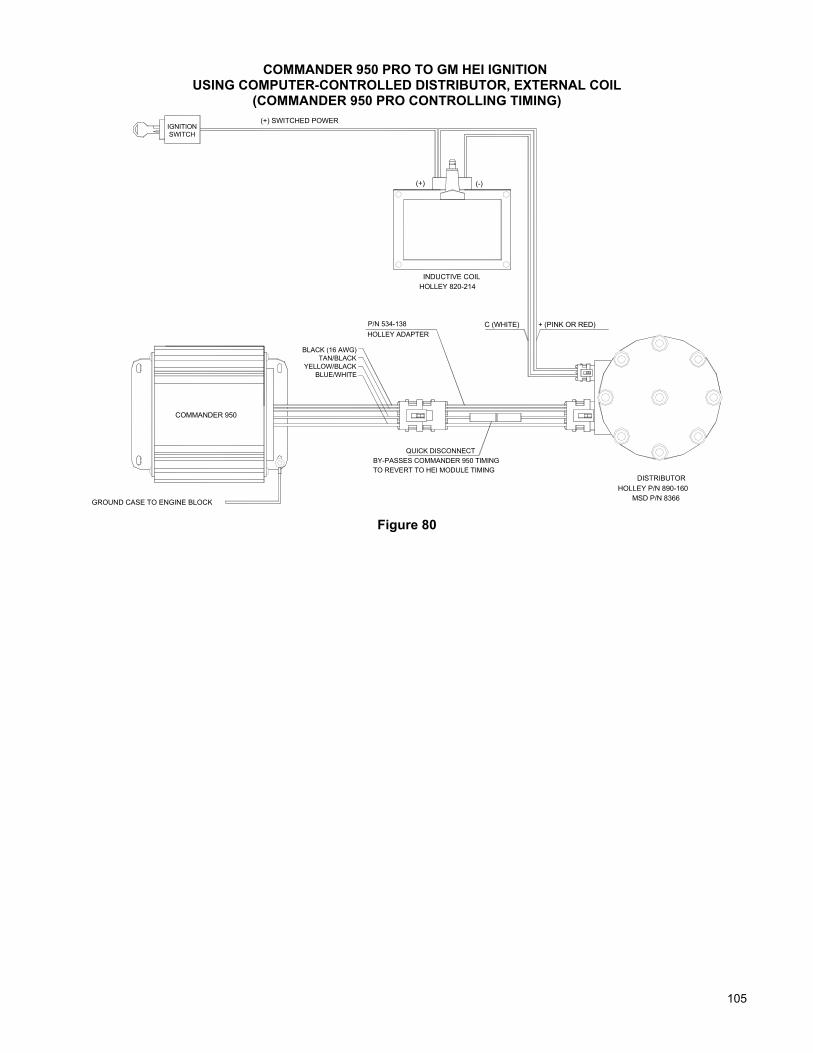
105
COMMANDER 950 PRO TO GM HEI IGNITION USING COMPUTER-CONTROLLED DISTRIBUTOR, EXTERNAL COIL
(COMMANDER 950 PRO CONTROLLING TIMING)
COMMANDER 950
QUICK DISCONNECTBY-PASSES COMMANDER 950 TIMING
BLACK (16 AWG)TAN/BLACK
YELLOW/BLACKBLUE/WHITE
HOLLEY ADAPTERP/N 534-138
TO REVERT TO HEI MODULE TIMING
INDUCTIVE COIL
IGNITIONSWITCH
(+) SWITCHED POWER
(-)(+)
C (WHITE) + (PINK OR RED)
GROUND CASE TO ENGINE BLOCK MSD P/N 8366HOLLEY P/N 890-160
DISTRIBUTOR
HOLLEY 820-214
Figure 80

106106
COMMANDER 950 PRO TO AFTERMARKET IGNITIONUSING A GM 7-PIN STYLE DISTRIBUTOR AND EXTERNAL COIL
(COMMANDER 950 PRO CONTROLLING IGNITION TIMING)
CO
MM
AN
DER
950
QU
ICK D
ISCO
NN
ECT
BY
-PA
SS
ES
CO
MM
AN
DE
R 950 TIM
ING
DIS
TRIB
UTO
R
BLA
CK
(16 AW
G)
TAN
/BLA
CK
YELLO
W/BLA
CK
BLU
E/W
HITE
HO
LLEY
ADAP
TERP
/N 534-138
TO R
EV
ER
T TO H
EI M
OD
ULE TIM
ING
HO
LLEY
P/N
890-160
IGN
ITION
SW
ITCH
(+) SW
ITCH
ED P
OW
ER
C (W
HITE)
+ (PIN
K O
R R
ED)
GR
OU
ND
CA
SE
TO EN
GIN
E BLO
CK
GR
EE
N (TO
CH
ASS
IS GR
OU
ND
)
HE
AV
Y R
ED (+)
+3
TAC
HO
METER
RPM
0
2110 9
(CR
AN
E: G
REE
N)
45
68
7 BR
OW
N
BA
TTERY
HE
AV
Y B
LACK (-)
RE
D (+) S
WITC
HED
POW
ER
-
OR
AN
GE (+)
BLA
CK
(-)
NO
T USE
DV
IOLE
T (+) AN
D G
REEN
(-)
OR
AN
GE
(+) AN
D BLAC
K (-)
CR
AN
E H
I-6 IGN
ITION
MS
D 6-S
ER
IES IG
NITIO
NH
OLLE
Y 800-S
ER
IES IG
NITIO
N
(PO
INTS
TRIG
GER
)W
HITE
MS
D P
/N 8366
HO
LLEY
P/N
820-100C
D C
OIL
(HA
RN
ES
S N
OT S
UPPLIED
)
NO
TE:
RO
UTE
THE
SE W
IRE
S A
WA
Y FR
OM
ALL O
THER
S
TO A
VO
ID IN
TER
FEREN
CE
Figure 81

107
COMMANDER 950 PRO TO AFTERMARKET IGNITIONUSING MAGNETIC PICK-UP DISTRIBUTOR
(COMMANDER 950 PRO “NOT” CONTROLLING IGNITION TIMING)
5
TACHOMETER
0
21
34
RPM109
768
BATTERY+ -
ORANGE (+) AND BLACK (-)
VIOLET (+) AND GREEN (-)
RED (+) SWITCHED POWER
(CRANE: GREEN)BROWN
HEAVY RED (+) HEAVY BLACK (-)
HOLLEY 800-SERIES IGNITIONMSD 6-SERIES IGNITIONCRANE HI-6 IGNITION
WHITE(NOT USED)
SWITCHIGNITION
ORANGE (+)
GREEN (TO CHASSIS GROUND)
BLACK (-)
DISTRIBUTOR
CD COIL
COMMANDER 950YELLOW/BLACK
GROUND CASE TO ENGINE BLOCK
SEE LISTED WIRECODES FOR YOUR
APPLICATION
ORANGE BLACKVIOLETORANGEGREENGM HEI (MODULE REMOVED) WHITEVIOLETMALLORY COMP ORANGEVIOLETMSD ORANGEBLACKHOLLEY REDNEGATIVE (-)DISTRIBUTOR TYPE POSITIVE (+)
FORD DURASPARK (MODULE REMOVED)CHRYSLER ELECTRONIC (MODULE REMOVED)
NOTE:ROUTE THESE WIRES AWAY FROM ALL OTHERS TO AVOID INTERFERENCE
Figure 82

108108
COMMANDER 950 PRO TO AFTERMARKET IGNITIONUSING MAGNETIC PICK-UP CRANK TRIGGER
(COMMANDER 950 PRO CONTROLLING IGNITION TIMING)
ORANGE (+) AND BLACK (-)
RED (+) SWITCHED POWERIGNITION
VIOLET (+)
GREEN (-)
APPLICATION
SEE LISTED WIRECODES FOR YOUR
CONNECTORWITH PLASTICWIRE TERMINALSINSTALL SUITABLE
MSD 6-SERIES IGNITION
SENSORPICKUP
TRIGGERWHEEL
CRANK
VIOLET (+) AND GREEN (-)NOT USED
GREEN (-)
VIOLET (+)
WHITE
0RPM
109
8765
432
1
+ -
TACHOMETER
BATTERY
HEAVY BLACK (-)
COMMANDER 950
CD COIL
ORANGE (+) BLACK (-)
GREEN (TO CHASSIS GROUND)
(POINTS TRIGGER)
CRANE HI-6 IGNITION
HOLLEY 800-SERIES IGNITION
(CRANE: GREEN)
GROUND CASE TO (-) TERMINAL OF BATTERY
CRANKTRIGGER
IGNITION SIGNAL FLOW CHART
SENDS SIGNAL TO
COMMANDER 950
SENDS SIGNAL TO
AFTERMARKET IGNITION BOX
SENDS SIGNAL TO
IGNITION COIL
WHICH FIRES
SPARK PLUG
HARNESS P/N534-135 (MAGNETIC PICK-UP)
MOROSOFIREPOWER
CRANK TRIGGER TYPE
MSD (LATE)MSD (EARLY)
HOLLEY LASERSTRIKE (EARLY)HOLLEY LASERSTRIKE (LATE)
NEGATIVE (-)POSITIVE (+)
VIOLETORANGE
GREY OR ORANGEBLACK
BLACK
VIOLET
WHITE
WHITEGREENBLACKGREENBLACK
NOTE:ROUTE THESE WIRES AWAY FROM ALL OTHERS TO AVOID INTERFERENCE
HEAVY RED (+)
WHITE
BROWN
SWITCH
Figure 83

109
COMMANDER 950 PRO TO AFTERMARKET IGNITIONUSING HALL EFFECT PICK-UP CRANK TRIGGER
(COMMANDER 950 PRO CONTROLLING IGNITION TIMING)
ORANGE (+) AND BLACK (-)
RED (+) SWITCHED POWERIGNITIONMSD 6-SERIES IGNITION
SENSORPICKUP
TRIGGERWHEEL
CRANK
HEAVY RED (+)
WHITE
BROWN
SWITCH
VIOLET (+) AND GREEN (-)NOT USED
0RPM
109
8765
432
1
+ -
TACHOMETER
BATTERY
HEAVY BLACK (-)
COMMANDER 950
CD COIL
ORANGE (+) BLACK (-)
GREEN (TO CHASSIS GROUND)
(POINTS TRIGGER)
CRANE HI-6 IGNITION
HOLLEY 800-SERIES IGNITION
(CRANE: GREEN)
GROUND CASE TO (-) TERMINAL OF BATTERY
CRANKTRIGGER
IGNITION SIGNAL FLOW CHART
SENDS SIGNAL TO
COMMANDER 950
SENDS SIGNAL TO
AFTERMARKET IGNITION BOX
SENDS SIGNAL TO
IGNITION COIL
WHICH FIRES
SPARK PLUG
BLACK
RED
WHITEYELLOW/BLACK
BLACK
NOTE:ROUTE THESE WIRES AWAY FROM ALL OTHERS TO AVOID INTERFERENCE
Figure 84

110110
D8
D16
D14
D15
D11
D12
D13
D9
D10
B2B12
D3
D6
D7
D4
D5
D1
D2
B7B11B10B9 B8 B4B6 B5 B3 B1C
15
C5
C2
C1
C3
C4
C10
C6
C7
C8
C9
C13
C11
C12
C14
C16
A1A2A3A4A5A6A7A8A9A10A11A12
Ignition
Serial Com
Connector
Ground
Battery
Fuel Pump
O2 Sensor
EC
T
MAP
MA
T
TPS IAC
IPU
Coil (-)
Vsw
itch
Park/N
eu Relay to provide pow
er for:Fuel Pum
pO
2 heaterInjectors
Points O
ut
InjectorsCE
BA
D
AC R
equest
FUSE
4321
Brow
nG
reen/Black
Green
Red/W
hite
YellowO
range
Black/W
hite
Red
Black
Yellow
/Black
Orange/R
edP
urpleD
ark Blue
Green
Purple/W
hiteP
urple/BlackP
urple/Yellow
Purple/Blue
White
Brow
nYellowB
lueG
reenO
range
Red
Black
Black/W
hiteB
lack/White
Blue/W
hiteTan/B
lackB
lack/White
Purple
Black
White/B
lueW
hite/Red
White/B
rown
White/G
reen
Red/B
lack
5 (86)1 (30)
4 (87)
2 (85)
ABCDCABCBAABCBAACDBACBCEADW
hite/Green
White/B
rown
White/R
edW
hite/BlueR
ed
Yellow
Tan/BlackB
lue/White
Yellow
/Black
Black
PurpleR
ed
Black
Green
Orange
Blue
Red/B
lack
Brow
n
Purple/White
Purple/B
lackP
urple/Yellow
Purple/B
lue
Green
Purple
Green/Black
Green/B
lack
Black
Red
Green/B
lack
Red
Black
Red/W
hite
Orange/R
ed
Light Blue
Brow
nG
reenY
ellowO
range
Black/W
hite
Red
White
C B A
A BCD
B A
BC
Black/W
hite
Black/W
hite
Black/W
hite
Black/W
hite
Orange
B
All connectors view
ed from end aw
ayfrom
the wires.
AD BAC B C A C B A
AC R
equest / Input 1
Battery
Injector D
NO
T USED
Injector AInjector BInjector C
NO
T USED
O2 S
ensor signal
Bypass
Output 1
NO
T USED
EC
U G
ND
Analog GN
D
EC
U G
ND
Analog GN
DE
ST / SPOU
T
Analog GN
D
IAC "A" Lo
Coolant Tem
pC
oil (-)M
AT singnalTP
S signal
NO
T USED
+5 Volt ref
NO
T USED
NO
T USED
Points O
ut
Fan Relay / O
utput 2
Park-N
eutral / Input 2
IAC "B" Lo
IAC
"B" Hi
IAC
"A" Hi
NO
T USED
IPU (-)
IPU (+)
Slew
Spark
TxDVehicle Speed
NO
T USED
EC
U G
ND
Slew
FuelR
ef / PIP
ESC
(knock)
MAP
Battery
NO
T USED
SER
IAL G
ND
(switched pow
er)
Fuel Pum
p Relay
NO
T USED
RxD
Vsw
itchN
OT U
SED
NO
T USED
ModB
ModA
Figure 85 G.M. TPI engines—P/N 271R865A

111
D8
D16
D14
D15
D11
D12
D13
D9
D10
B2
B12
D3
D6
D7
D4
D5
D1
D2
B7
B11
B10
B9
B8
B4
B6
B5
B3
B1C15
C5
C2
C1
C3
C4
C10
C6
C7
C8
C9
C13
C11
C12
C14
C16
A1A2A3A4A5A6A7A8A9A10A11A12
Ignition
Serial Com
Connector
Ground
Battery
Fuel Pump
O2 Sensor
EC
T
MAP
TPS IPU
Coil (-)
Vsw
itch
Park/N
eu Relay to provide pow
er for:Fuel P
ump
O2 heater
Injectors
Points O
ut
InjectorsCE
B
AC
Request / Input 1
Battery
Injector D
NO
T USED
Injector AInjector BInjector C
NO
T USED
O2 Sensor signal
Bypass
Output 1
NO
T USED
EC
U G
ND
Analog G
ND
EC
U G
ND
Analog G
ND
ES
T / SPO
UT
Analog G
ND
IAC
"A" Lo
Coolant Tem
pC
oil (-)M
AT singnal
TPS
signal
NO
T US
ED+5 Volt ref
NO
T US
EDN
OT U
SED
Points O
ut
Fan Relay / O
utput 2
Park-N
eutral / Input 2
IAC
"B" LoIA
C "B" H
iIA
C "A" H
i
NO
T US
ED
IPU
(-)
IPU
(+)
Slew
Spark
TxDVehicle S
peed
NO
T USED
EC
U G
ND
Slew
FuelR
ef / PIP
ESC
(knock)
MA
P
Battery
NO
T US
EDSE
RIA
L GN
D
(switched pow
er)
Fuel Pum
p Relay
NO
T US
ED
RxD
Vswitch
NO
T US
ED
NO
T US
ED
ModB
ModA
White
B A
Black/W
hite
Black/W
hite
Black/White
Black/W
hite
Orange
B
All connectors view
ed from end aw
ayfrom
the wires.
IAC
MA
T
CBA B A
BC AACD B C AB
CA B
A
D
AC
Request
FUS
E
4321
Brow
nG
reen/Black
Green
Red/W
hite
Yellow
Orange
Black/W
hite
Red
Black
Yellow
/Black
Orange/R
edP
urpleD
ark BlueG
reen
Purple/W
hiteP
urple/BlackP
urple/YellowP
urple/Blue
White
Brow
nY
ellowB
lueG
reenO
range
Red
Black
Black/W
hiteB
lack/White
Blue/W
hiteTan/BlackB
lack/White
Purple
Black
White/B
lueW
hite/Red
White/B
rown
White/G
reen
Red/Black
5 (86)
1 (30)4 (87)2 (85)
ABCCBDACBAABCB AACDBACBCEADW
hite/Green
White/Brow
nW
hite/Red
White/Blue
Red
Yellow
Tan/Black
Blue/W
hiteY
ellow/Black
Black
Purple
Red
Black
Green
Orange
Blue
Red/B
lack
Brown
Purple/W
hiteP
urple/BlackP
urple/YellowP
urple/Blue
Green
Purple
Green/B
lack
Green/B
lack
Black
Red
Green/B
lack
Red
Black
Red/W
hite
Orange/R
ed
Light Blue
BrownGreen
Yellow
Orange
Black/W
hite
Red
Figure 86 Holley SBC & BBC MPFI—P/N 271R875A

112112
IPU
(-)
IPU
(+)
Slew
Spark
TxDV
ehicle Speed
NO
T US
ED
EC
U G
ND
Slew
FuelR
ef / PIP
ES
C (knock)
MA
P
Battery
NO
T USE
DS
ER
IAL G
ND
(switched pow
er)
Fuel Pump R
elay
NO
T USE
D
RxD
Vsw
itchN
OT U
SED
NO
T USE
D
ModB
ModA
AC
Request / Input 1
Battery
Injector D
NO
T US
ED
Injector AInjector BInjector C
NO
T US
ED
O2 S
ensor signal
Bypass
Output 1
NO
T US
ED
EC
U G
ND
Analog G
ND
EC
U G
ND
Analog G
ND
ES
T / SPO
UT
Analog G
ND
IAC "A
" Lo
Coolant Tem
pC
oil (-)M
AT singnal
TPS
signal
NO
T US
ED
+5 Volt ref
NO
T US
ED
NO
T US
ED
Points O
ut
Fan Relay / O
utput 2
Park-N
eutral / Input 2
IAC "B
" LoIAC
"B" H
iIAC
"A" H
i
NO
T US
ED
Points O
ut
Purple/Y
ellow
D3
Black/W
hite
D10
D14
D16
D15
D12
D13
D11
White/R
ed
White/G
reenW
hite/Brow
n
White/Blue
D8
D9
D7
D5
D6
D4
Purple
Black
Black/W
hiteTan/B
lackB
lue/White
Blue
C12
D1
D2 C16
C14
C15
C13
Red
Black/W
hiteB
lack
Orange
Green
C8
C10
C11
C9
C6
C7
C5
Brow
nY
ellow
White
Purple/B
lue
B2
Dark B
lue
C1
C4
C3
C2
B11
B12
B10
Purple/B
lackP
urple/White
Green
B6
B8
B9
B7
B4
B5
B3
Orange/R
edP
urple
Red/B
lackY
ellow/B
lack
Black
A7
B1 A12
A11
A9
A10
A8
Black/W
hite
Red
Orange
Yellow
A3
A5
A6
A4
A1
A2
Red/W
hite
Green/B
lackB
rown
Green
1 2 3 4B
rown
Black/W
hite
Orange
Green
Yellow
Serial C
omC
onnector
DTan/Black
C
All connectors view
ed from end aw
ayfrom
the wires.
White/B
lueW
hite/Red
White/B
rown
White/G
reen
YellowR
ed
DB
Coil (-)
BEA CCE
A
DInjectors
Ignition
MA
P
Orange
Black/W
hite
BlackB
lackY
ellow/Black
Blue/W
hite
Red
Purple
Green
BC
IAC
IPU
Black
Ground
Red
Battery
Green/B
lack
2 (85)G
reen/Black
Fuel Pump
BA D B
AC B C
A BA C
A BC A
Black/W
hite
Black/W
hite
Black/W
hite
Red/B
lack
Blue
Orange
Brow
n
AB AB A C
CB B A
AB
O2 S
ensor
TPS
MA
T
EC
T
Red
4 (87)R
elay to provide power for:
Fuel Pump
O2 heater
Injectors
Purple/B
lueP
urple/Yellow
Purple/Black
Purple/W
hite
White
Purple
Green
C
BA D C BC A
B A
Light Blue
Orange/R
ed
Red/W
hite
1 (30)
5 (86)B
lack
Green/B
lackR
ed
AC
Request
Park/N
eu
FUS
E
Vsw
itch
Figure 87 Holley 4 BBL TBI—P/N 271R884A

113
C6
Bypass
NO
T US
ED
Injector DInjector CInjector BInjector A
O2 Se nsor signal
Analog G
ND
NO
T US
EDE
CU
GN
D
NO
Senable
NO
S1
+5 Volt refN
OT U
SED
Analog G
ND
ES
T / SPO
UT
Analog G
ND
EC
U G
ND
Battery
Coolant Tem
p
TPS
signa lM
AT singnal
Points O
utN
OT U
SED
NO
T USE
D
Coil (-)
D12
White/G
reenW
hite/Brow
nW
hit e/Red
Wh ite/Blue
D16
D13
D15
D14
Blac k
Purple
Black/W
hite
D8
D11
D10
D9
D7
D5
D6 C14
Orange
Black/W
hiteB
lack/White
Blac k
D1
D3
D4
D2 C16
C15
Red
Green
Brow
nW
hite
C10
C11
C1 2
C13
Blue
C8
C9
C7
Fuel Pum
p Relay
MA
P
NO
T USE
D
IAC
" A" LoIA
C "A
" Hi
I AC
"B" H
iIA
C "B" Lo
Cooling Fan R
e lay
Slew
Spark
AC
Request
ESC
(k nock)
Park / N
eutralIPU
(+ )
IPU (-)
Ref / PIP
Slew
Fuel
TxD
SE
RIA
L GN
DN
OT U
SED
Vehicle S
peed
EC
U G
ND
NO
T US
EDB
attery
NO
T USE
D
NO
T USE
DN
OT U
SED
Vsw
itch (sw
itched power)
RxD
Mod A
ModB
A1
Brow
n
B4B1 1
Purple/B
lueP
urple /Yellow
Purple/Blac k
Purple/W
h ite
C5
C4
C3
B12
C1
C2
Yellow
/Black
Green
Dark Blu e
Purple
Orange/R
edB8B
10B9 B6B7 B 5 A
9O
range
Red/B
lackB
lack
Black/W
hite
B2B3 B1R
ed
A11
A12
A10
Yellow
Red/W
hite
Green
A5
A7
A8
A6
A3
A4
A2
Brow
n
Green/B
lack
3Y
ellowBlack/W
hite
Oran ge
21
Green
4
Serial C
omC
onnector
AB
All connecto rs view
ed from end aw
ayfrom
t he wires.
Inject ors
Wh ite/Blue
White/ R
edW
hite/Bro w
nW
hite/Green
Red
ED A BC
AB
E CD
MA
T
HALL
EF FE
CT
O2
Sensor
CC
TPS
Yellow
/Blac kR
ed/White
Black
Purple
Red
Black
Black/W
hite
BC AAC B
ACB B
BC A A
Orange
Green
Black/W
hiteB
lue
Black/W
hiteR
ed /Black
Orange
Blac k/W
hite
BA A
B BA
CA B
AC BM
AP
Red
Relay to pro vide pow
er for:Fuel Pum
pO
2 h eaterInjectors
IAC
IPU
Purple /W
hite
Purple/B
lueP
urple/Yello w
Purp le/Black
Brow
n
White
Purple
Green
AA CB D
BE
CT
CA B D
BC A
BC A
Orange/R
e d
Light Blue
Black
Red/W
hi te
5 (86)
Par k/N
eu
FUS E
AC
Reque st
Vsw
itch
Black
Red
Ba ttery
Ground
Green/B
lack
Green/B
l ack
Green/B
lackR
ed2 (85)4 (87 )1 (30)
F uel Pum
p
Figure 88 G.M. LT1/LT4 engine—P/N 271R886A

114114
Holley Performance Products1801 Russellville Road
Bowling Green, KY 42101-3542
Toll Free Technical Service: 1-866-GOHOLLEYTechnical Service: 1-270-781-9741
Fax: 1-270-781-9772For online help, please refer to the Tech Service section of our website: www.holley.com
Holley Performance Products Limited Warranty
All Holley Performance Products Limited Warranties are extended to the original consumer only. This Limited Warranty is not assignable orotherwise transferable. There are no warranties that extend beyond those stated herein. Holley Performance Products offers no otherwarranties expressed or implied beyond this Limited Warranty.
In the event of an alleged defect in material or workmanship, Holley Performance Products’ responsibility is strictly limited to repair or replace thedefective product. Holley has no other obligation expressed or implied. Final warranty determination will be in the sole discretion of HolleyPerformance Products. Holley shall not be responsible for; (a) actual or alleged labor, transportation, or other incidental charges; or (b) actual oralleged consequential or other damages incurred by use of any product of Holley Performance Products.
To initiate the warranty process, the consumer must return the alleged defective product to the place of purchase with a dated receipt andcompleted applicable warranty claim tag. Warranty claims will be rejected if the date of purchase cannot be established by the consumer. Donot send products directly to Holley Performance Products. Holley Performance Products assumes no responsibility for products sent directly toHolley Performance Products.
This Limited Warranty sets forth specific legal rights. The consumer may have other rights as a result of variations in state laws or provinciallaws. This Limited Warranty supersedes all prior warranty statements.
HOLLEY/ANNIHILATOR/FLOWTECH/HOOKER/NOS/WEIAND – NEW PRODUCT
Holley Performance Products warrants its new Holley, Annihilator, Flowtech, Hooker, NOS, and Weiand products to be free from defects inmaterial and workmanship for a period of 90 days from date of purchase.
Holley Performance Products Limited Warranty specifically does not apply to products, which have been (a) modified or altered in any way; (b)subjected to adverse conditions, such as misuse, neglect, accident, improper installation or adjustment, dirt or other contaminants, water,corrosion, or faulty repair; or (c) used in other than those applications recommended by Holley Performance Products. Holley PerformanceProducts also does not warrant, and disclaims all liability for products used in racing activities and/or applications other than those specificallyrecommended in the current brand catalog.
Holley limits the warranty on Metallic Ceramic Coatings to be free from defects in material and workmanship for a period of 90 days from thedate of purchase. This limited coating warranty does not apply to any products which have been subjected to adverse conditions, such as highheat encountered during engine break-in or if used during any racing activity.
MARINE PRODUCTS
Holley Performance Products warrants its new marine products to be free from defects in material and workmanship for a period of 90 days fromdate of purchase. For the safety and protection of persons and property, all United States Coast Guard and other marine product safetyinstallation and use requirements and recommendations must be carefully studied and applied. The above recommendations include, but arenot limited to the recommendation that the installation, adjustment, and repair of Holley carburetors or other marine products must be performedonly by a trained mechanic having adequate marine fuel system experience, and in strict compliance with the applicable Holley installation,maintenance, and other instructions. Failure to follow such requirements and recommendations will void this Holley Marine Limited Warranty,and Holley disclaims any responsibility and/or liability for accidents resulting from such failure.
Holley Performance Products Limited Warranty specifically does not apply to products, which have been (a) modified or altered in any way; (b)subjected to adverse conditions, such as misuse, neglect, accident, improper installation or adjustment, dirt or other contaminants, water,corrosion, or faulty repair; or (c) used in other than those applications recommended by Holley Performance Products. Holley PerformanceProducts also does not warrant, and disclaims all liability for products used in racing activities and/or applications other than those specificallyrecommended in the current brand catalog.
HolleyPrinted in U.S.A. 199R-10149-7 Date: 7-12-04 Performance Products, Inc.
Copyright © 2004 by Holley Performance Products, Inc. Any unauthorized reproduction of this manual without the express written
permission of Holley Performance Products, Inc. is strictly prohibited.