commercial energy efficiency
TRANSCRIPT

CHAPTER 5
COMMERCIAL ENERGY EFFICIENCY
This chapter has been reformatted; some deletions are not marked, relocated sections are not marked. SECTION ECC 501
GENERAL
*501.1 Scope.
The requirements contained in this chapter are applicable to commercial buildings, or portions of commercial buildings. These commercial
buildings shall meet either the requirements of ASHRAE/IESNA Standard 90.1, Energy Standard for Buildings Except for Low-Rise
Residential Buildings, as modified for New York City by Appendix A of this code, or the requirements contained in this chapter.
*Section ECC 501.1 was amended by: Local Law 48 of 2010 – Update #50. This law has an effective date of December 28, 2010.
501.2 Application.
The commercial building project shall comply with the requirements in Sections ECC 502 (Building envelope requirements), ECC 503
(Building mechanical systems), ECC 504 (Service water heating) and ECC 505 (Electrical power and lighting systems) in its entirety. As an
alternative the commercial building project shall comply with the requirements of ASHRAE/IESNA 90.1 in its entirety.
Exception: Buildings conforming to Section ECC 506, provided Sections 502.4, 502.5, 503.2, ECC 504, 505.2, 505.3, 505.4, 505.6 and
505.7 are each satisfied.
SECTION ECC 502
BUILDING ENVELOPE REQUIREMENTS
502.1 General (Prescriptive).
502.1.1 Insulation and fenestration criteria.
The building thermal envelope shall meet the requirements of Tables 502.2(1) and 502.3 based on the climate zone specified in Chapter
3. Commercial buildings or portions of commercial buildings enclosing Group R occupancies shall use the R-values from the “Group R”
column of Table 502.2(1). Commercial buildings or portions of commercial buildings enclosing occupancies other than Group R shall
use the R-values from the “All other” column of Table 502.2(1). Buildings with a vertical fenestration area or skylight area that exceeds
that allowed in Table 502.3 shall comply with the building envelope provisions of ASHRAE/IESNA 90.1.
502.1.2 U-factor alternative.
An assembly with a U-factor, C-factor, or F-factor equal to or less than that specified in Table 502.1.2 shall be permitted as an alternative
to the R-value in Table 502.2(1). Commercial buildings or portions of commercial buildings enclosing Group R occupancies shall use the
U-factor, C-factor, or F-factor from the “Group R” column of Table 502.1.2. Commercial buildings or portions of commercial buildings
enclosing occupancies other than Group R shall use the U-factor, C-factor or F-factor from the “All other” column of Table 502.1.2.
502.2 Specific insulation requirements (Prescriptive).
Opaque assemblies shall comply with Table 502.2(1).

TABLE 502.1.2 BUILDING ENVELOPE REQUIREMENTS - OPAQUE ELEMENT, MAXIMUM U-FACTORS
CLIMATE ZONE 4 5 6
ALL OTHER GROUP R ALL OTHER GROUP R ALL OTHER GROUP R
Roofs
Insulation entirely above deck
U-0.048 U-0.048 U-0.048 U-0.048 U-0.048 U-0.048
Metal buildings U-0.055 U-0.055 U-0.055 U-0.055 U-0.049 U-0.049
Attic and other U-0.027 U-0.027 U-0.027 U-0.027 U-0.027 U-0.027
Walls, Above Grade
Mass U-0.104 U-0.090 U-0.090 U-0.080 U-0.080 U-0.071
Metal building U-0.084 U-0.084 U-0.069 U-0.069 U-0.069 U-0.069
Metal framed U-0.064 U-0.064 U-0.064 U-0.064 U-0.064 U-0.064
Wood framed and other
U-0.089 U-0.064 U-0.064 U-0.051 U-0.051 U-0.051
Below-Grade Wallsa
Below-grade wallsa C-1.140 C-0.119 C-0.119 C-0.119 C-0.119 C-0.119
Floors
Mass U-0.087 U-0.074 U-0.074 U-0.064 U-0.064 U-0.057
Joist/Framing U-0.033 U-0.033 U-0.033 U-0.033 U-0.033 U-0.033
Slab-on-Grade Floors
Unheated slabs F-0.730 F-0.540 F-0.730 F-0.540 F-0.540 F-0.520
Heated slabs F-0.860 F-0.860 F-0.860 F-0.860 F-0.860 F-0.688 a. When heated slabs are placed below grade, below-grade walls must meet the F-factor requirements for perimeter insulation according to the heated slab-on-
grade construction.
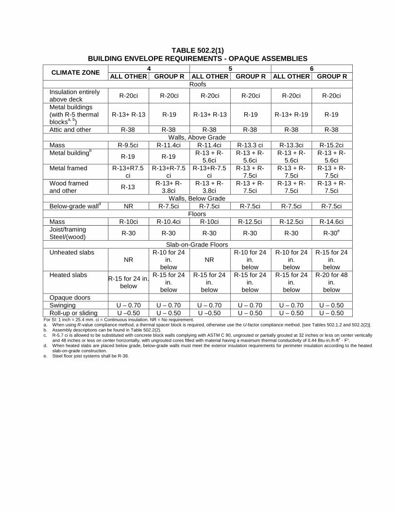
TABLE 502.2(1) BUILDING ENVELOPE REQUIREMENTS - OPAQUE ASSEMBLIES
CLIMATE ZONE 4 5 6
ALL OTHER GROUP R ALL OTHER GROUP R ALL OTHER GROUP R
Roofs
Insulation entirely above deck
R-20ci R-20ci R-20ci R-20ci R-20ci R-20ci
Metal buildings (with R-5 thermal blocks
a, b)
R-13+ R-13 R-19 R-13+ R-13 R-19 R-13+ R-19 R-19
Attic and other R-38 R-38 R-38 R-38 R-38 R-38
Walls, Above Grade
Mass R-9.5ci R-11.4ci R-11.4ci R-13.3 ci R-13.3ci R-15.2ci
Metal buildingb
R-19 R-19 R-13 + R-
5.6ci R-13 + R-
5.6ci R-13 + R-
5.6ci R-13 + R-
5.6ci
Metal framed R-13+R7.5 ci
R-13+R-7.5 ci
R-13+R-7.5 ci
R-13 + R-7.5ci
R-13 + R-7.5ci
R-13 + R-7.5ci
Wood framed and other
R-13 R-13+ R-
3.8ci R-13 + R-
3.8ci R-13 + R-
7.5ci R-13 + R-
7.5ci R-13 + R-
7.5ci
Walls, Below Grade
Below-grade walld NR R-7.5ci R-7.5ci R-7.5ci R-7.5ci R-7.5ci
Floors
Mass R-10ci R-10.4ci R-10ci R-12.5ci R-12.5ci R-14.6ci
Joist/framing Steel/(wood)
R-30 R-30 R-30 R-30 R-30 R-30e
Slab-on-Grade Floors
Unheated slabs NR
R-10 for 24 in.
below NR
R-10 for 24 in.
below
R-10 for 24 in.
below
R-15 for 24 in.
below
Heated slabs R-15 for 24 in.
below
R-15 for 24 in.
below
R-15 for 24 in.
below
R-15 for 24 in.
below
R-15 for 24 in.
below
R-20 for 48 in.
below
Opaque doors
Swinging U – 0.70 U – 0.70 U – 0.70 U – 0.70 U – 0.70 U – 0.50
Roll-up or sliding U –0.50 U – 0.50 U –0.50 U – 0.50 U – 0.50 U – 0.50 For SI: 1 inch = 25.4 mm. ci = Continuous insulation. NR = No requirement. a. When using R-value compliance method, a thermal spacer block is required, otherwise use the U-factor compliance method. [see Tables 502.1.2 and 502.2(2)]. b. Assembly descriptions can be found in Table 502.2(2). c. R-5.7 ci is allowed to be substituted with concrete block walls complying with ASTM C 90, ungrouted or partially grouted at 32 inches or less on center vertically
and 48 inches or less on center horizontally, with ungrouted cores filled with material having a maximum thermal conductivity of 0.44 Btu-in./h-ft2 · F°.
d. When heated slabs are placed below grade, below-grade walls must meet the exterior insulation requirements for perimeter insulation according to the heated slab-on-grade construction.
e. Steel floor joist systems shall be R-38.

TABLE 502.2(2) BUILDING ENVELOPE REQUIREMENTS–OPAQUE ASSEMBLIES
R-VALUE DESCRIPTION REFERENCE
ROOFS
R-19 Standing seam roof with single fiberglass insulation layer. This construction is R-19 faced fiberglass insulation batts draped perpendicular over the purlins. A minimum R-3.5 thermal spacer block is placed above the purlin/batt, and the roof deck is secured to the purlins.
ASHRAE/IESNA 90.1 Table A2.3 including
Addendum “G”
R-13 + R-13 R-13 + R-19
Standing seam roof with two fiberglass insulation layers. The first R-value is for faced fiberglass insulation batts draped over purlins. The second R-value is for unfaced fiberglass insulation batts installed parallel to the purlins. A minimum R-3.5 thermal spacer block is placed above the purlin/batt, and the roof deck is secured to the purlins.
ASHRAE/IESNA 90.1 Table A2.3 including
Addendum “G”
R-11 + R-19 FC
Filled cavity fiberglass insulation. A continuous vapor barrier is installed below the purlins and uninterrupted by framing members. Both layers of uncompressed, unfaced fiberglass insulation rest on top of the vapor barrier and are installed parallel, between the purlins. A minimum R-3.5 thermal spacer block is placed above the purlin/batt, and the roof deck is secured to the purlins.
ASHRAE/IESNA 90.1 Table A2.3 including
Addendum “G”
WALLS
R-16, R-19 Single fiberglass insulation layer. The construction is faced fiberglass insulation batts installed vertically and compressed between the metal wall panels and the steel framing.
ASHRAE/IESNA 90.1 Table A3.2 including
Addendum “G”
R-13 + R-5.6 ci R-19 + R-5.6 ci
The first R-value is for faced fiberglass insulation batts installed perpendicular and compressed between the metal wall panels and the steel framing. The second rated R-value is for continuous rigid insulation installed between the metal wall panel and steel framing, or on the interior of the steel framing.
ASHRAE/IESNA 90.1 Table A3.2 including
Addendum “G”
502.2.1 Roof assembly.
The minimum thermal resistance (R-value) of the insulating material installed either between the roof framing or continuously on the
roof assembly shall be as specified in Table 502.2(1), based on construction materials used in the roof assembly.
Exception: Continuously insulated roof assemblies where the average area-weighted U-factor is equivalent to the same assembly with
the R-value specified in Table 502.2(1).
Insulation installed on a suspended ceiling with removable ceiling tiles shall not be considered part of the minimum thermal
resistance of the roof insulation.
502.2.2 Classification of walls.
Walls associated with the building envelope shall be classified in accordance with Section 502.2.2.1 or 502.2.2.2.
502.2.2.1 Above-grade walls.

Above-grade walls are those walls covered by Section 502.2.3 on the exterior of the building and completely above grade or walls that
are more than 15 percent above grade.
502.2.2.2 Below-grade walls.
Below-grade walls covered by Section 502.2.4 are basement or first-story walls associated with the exterior of the building that are at
least 85 percent below grade.
502.2.3 Above-grade walls.
The minimum thermal resistance (R-value) of the insulating material(s) installed in the wall cavity between the framing members and
continuously on the walls shall be as specified in Table 502.2(1), based on framing type and construction materials used in the wall
assembly. The R-value of integral insulation installed in concrete masonry units (CMU) shall not be used in determining compliance with
Table 502.2(1). “Mass walls” shall include walls weighing at least (1) 35 pounds per square foot (170 kg/m2) of wall surface area or (2)
25 pounds per square foot (120 kg/m2) of wall surface area if the material weight is not more than 120 pounds per cubic foot (1900
kg/m3).
502.2.4 Below-grade walls.
The minimum thermal resistance (R-value) of the insulating material installed in, or continuously on, the below-grade walls shall be as
specified in Table 502.2(1), and shall extend to a depth of 10 feet (3048 mm) below the outside finish ground level, or to the level of the
floor, whichever is less.
502.2.5 Floors over outdoor air or unconditioned space.
The minimum thermal resistance (R-value) of the insulating material installed either between the floor framing or continuously on the
floor assembly shall be as specified in Table 502.2(1), based on construction materials used in the floor assembly. “Mass floors” shall
include floors weighing at least (1) 35 pounds per square foot (170 kg/m2) of floor surface area or (2) 25 pounds per square foot (170
kg/m2) of floor surface area if the material weight is not more than 12 pounds per cubic foot (1900 kg/m
3).
502.2.6 Slabs on grade.
The minimum thermal resistance (R-value) of the insulation around the perimeter of unheated or heated slab-on-grade floors shall be as
specified in Table 502.2(1). The insulation shall be placed on the outside of the foundation or on the inside of a foundation wall. The
insulation shall extend downward from the top of the slab for a minimum distance as shown in the table or to the top of the footing,
whichever is less, or downward to at least the bottom of the slab and then horizontally to the interior or exterior for the total distance
shown in the table.
502.2.7 Opaque doors.
Opaque doors (doors having less than 50 percent glass area) shall meet the applicable requirements for doors as specified in Table
502.2(1) and be considered as part of the gross area of above-grade walls that are part of the building envelope.
502.2.8 Siding attachment over foam sheathing.
In areas where the basic wind speed is less than 100 mph (45 m/s), siding shall be attached over foam sheathing in accordance with
Section 502.2.8.1, Section 502.2.8.2, or an approved design. In all other areas, siding attachments shall be in accordance with an
approved design. In no case shall the siding material be used in a manner that exceeds its application limits. When required by the basic
wind speed and wind exposure applicability of the Building Code of New York State, Section 1706, wall cladding installation over foam
sheathing shall be subject to special inspection in accordance with the Building Code of New York State, Section 1706.4.
Exception: Where the siding manufacturer has provided approved installation instructions for application over foam sheathing, those
requirements shall apply.
502.2.8.1 Direct siding attachment.
Approved weather coverings installed directly over foam sheathing without separation by an air space shall comply with Table
502.2.8.1 in regard to minimum fastening requirements and maximum foam sheathing thickness limitations to support siding dead
load. The siding fastener and siding installation shall otherwise comply with the Building Code of New York State, Chapter 14, shall be
capable of resisting all other applicable design loads determined in accordance with the Building Code of New York State, Chapter 16,
and in no case shall result in a less stringent fastening requirement than required by the Building Code of New York State, Chapter 14
or the manufacturer’s installation instructions for the specific siding material used.
Exception: For exterior insulation and finish systems, refer to the Building Code of New York State, Section 1408.

TABLE 502.2.8.1 SIDING MINIMUM FASTENING REQUIREMENTS FOR DIRECT SIDING ATTACHMENT
OVER FOAM PLASTIC SHEATHING TO SUPPORT SIDING DEAD LOAD1
SIDING FASTENER TYPE AND
MINIMUM SIZE2
SIDING FASTENER VERTICA SPACING (INCHES)
MAXIMUM FOAM SHEATHING THICKNESS (INCHES)
16 oc Fastener Horizontal Spacing
24 oc Fastener Horizontal Spacing
Siding Weight: Siding Weight:
3 psf 11 psf 25 psf 3 psf 11 psf 25 psf
Wood Framing
(minimum 1-1/4 inch
penetration)
0.113 diameter nail
6 4 3 1 4 2 0.75
8 4 2 0.75 4 1.5 DR
12 4 1.5 DR 3 0.75 DR
0.120 diameter nail
6 4 3 1.5 4 2 0.75
8 4 2 1 4 1.5 0.5
12 4 1.5 0.5 3 1 DR
0.131 diameter nail
6 4 4 1.5 4 3 1
8 4 3 1 4 2 0.75
12 4 2 0.75 4 1 DR
Steel Framing (minimum
penetration of steel
thickness + 3 threads)
#8 screw into 33 mil steel
or thicker
6 3 3 1.5 3 2 DR
8 3 2 0.5 3 1.5 DR
12 3 1.5 DR 3 0.75 DR
#10 screw into 33 mil steel
6 4 3 2 4 3 0.5
8 4 3 1 4 2 DR
12 4 2 DR 3 1 DR
#10 screw into 43 mil steel or thicker
6 4 4 3 4 4 2
8 4 4 2 4 3 1.5
12 4 3 1.5 4 3 DR For SI: 1 inch = 25.4 mm; 1 pound per square foot (psf) = 0.0479 kPa. DR = design required. 1. Tabulated requirements are based on wood framing of Spruce-Pine-Fir or any wood species with a specific gravity of 0.42 or greater in accordance with
AFPA/NDS and minimum 33 ksi steel for 33 mil and 43 mil steel and 50 ksi steel for 54 mil steel or thicker. 2. Nail fasteners shall comply with ASTM F1667, except nail length shall be permitted to exceed ASTM F1667 standard lengths. Self-drilling tapping screw
fasteners for connection of siding to steel framing shall comply with the requirements of AISI S200. Specified fasteners in accordance with Chapter 1405 or the siding manufacturer’s approved installation instructions shall meet all other requirements in ASTM F1667, AISI S200 or be otherwise approved for the intended application.
502.2.8.2 Offset siding attachment.
When an airspace separates the siding from direct contact with the foam plastic sheathing, the approved weather coverings shall be
attached in accordance with the Building Code of New York State, Chapter 14 to minimum 1 × 3 wood or minimum 33 mil steel hat
channel furring placed over the foam sheathing. Furring shall be attached through the foam sheathing to wall framing in accordance
with Table 502.2.8.2 in regard to minimum fastening requirements and maximum foam sheathing thickness limitations to support
siding dead load. Furring and connections shall be separately designed to resist all other applicable loads determined in accordance
with the Building Code of New York State, Chapter 16. When placed horizontally, wood furring shall be preservative-treated wood in
accordance with the Building Code of New York State, Section 2303.1.8 or naturally durable wood and fasteners shall be corrosion
resistant in accordance with the Building Code of New York State, Section 2304.9.5. Steel hat channel furring shall have a minimum
G60 galvanized coating.
Exception: Furring shall not be required over foam plastic sheathing behind anchored stone and masonry veneer installed in
accordance with the Building Code of New York State, Section 1405.6. Veneer ties shall be installed on the surface of the foam
plastic sheathing with fasteners of sufficient length to pass through the thickness of foam plastic sheathing and penetrate framing to
provide required pull-out resistance determined in accordance with the Building Code of New York State, Chapter 16.

TABLE 502.2.8.2 FURRING MINIMUM FASTENING REQUIREMENTS FOR APPLICATION OVER
FOAM PLASTIC SHEATHING TO SUPPORT SIDING DEAD LOAD1,2
FURRING MATERIAL
FRAMING MEMBER
FASTENER TYPE AND
MINIMUM SIZE
MINIMUM PENETRATION
INTO WALL FRAMING (inches)
FASTENER SPACING IN
FURRING (inches)
MAXIMUM THICKNESS OF FOAM SHEATHING
(inches)
16oc Furring4 24oc Furring
4
Siding Weight: Siding Weight:
3 psf 11 psf 25 psf 3 psf 11 psf 25 psf
Minimum 1 × Wood Furring
3
Minimum 2 × Wood
Stud
0.120diameter
nail
1¼
8 4 4 1.5 4 2 1
12 4 2 1 4 1.5 0.5
16 4 2 0.5 4 1 DR
0.131diameter
nail
1¼
8 4 4 2 4 3 1
12 4 3 1 4 2 0.75
16 4 2 0.75 4 1.5 DR
#8 wood screw
5
1
12 4 4 1.5 4 3 1
16 4 3 1 4 2 0.5
24 4 2 0.5 4 1 DR
¼” lag screw
5
1½
12 4 4 3 4 4 1.5
16 4 4 2 4 3 1
24 4 3 1 4 2 0.5
Minimum 33 mil Steel Hat
Channel or
Minimum 1 × Wood Furring
3
33 mil Steel Stud
#8 screw Steel thickness
+ 3 threads
12 3 1.5 DR 3 0.5 DR
16 3 1 DR 2 DR DR
24 2 DR DR 2 DR DR
#10 screw Steel thickness
+ 3 threads
12 4 2 R 4 1 DR
16 4 1.5 DR 3 DR DR
24 3 DR DR 2 DR DR
43 mil or thicker
Steel Stud
#8 screw Steel thickness
+ 3 threads
12 3 1.5 DR 3 0.5 DR
16 3 1 DR 2 DR DR
24 2 DR DR 2 DR DR
#10 screw Steel thickness
+ 3 threads
12 4 3 1.5 4 3 DR
16 4 3 0.5 4 2 DR
24 4 2 DR 4 0.5 DR For SI: 1 inch = 25.4 mm; 1 pound per square foot (psf) = 0.0479 kPa. DR = design required. 1. Table values are based on: (1) minimum ¾-inch (19.1 mm) thick wood furring and wood studs of Spruce-Pine-Fir or any softwood species with a specific
gravity of 0.42 or greater per AFPA/NDS, (2) minimum 33 mil steel hat channel furring of 33 ksi steel, and (3) steel framing of indicated nominal steel thickness and minimum 33 ksi steel for 33 mil and 43 mil steel and 50 ksi steel for 54 mil steel or thicker.
2. Nail fasteners shall comply with ASTM F1667, except nail length shall be permitted to exceed ASTM F1667 standard lengths. Self-drilling tapping screw fasteners for connection of siding to steel framing shall comply with the requirements of AISI S230. Specified fasteners in accordance with the Building Code
of New York State, Chapter 1405 or the siding manufacturer’s approved installation instructions shall meet all other requirements in ASTM F1667 or AISI S230 or be otherwise approved for the intended application.
3. Where the required siding fastener penetration into wood material exceeds ¾ inch (19.1 mm) and is not more than 1½ inches (38.1 mm), a minimum 2 × wood furring shall be used unless approved deformed shank siding nails or siding screws are used to provide equivalent withdrawal strength allowing connection to 1× wood furring.
4. Furring shall be spaced a maximum of 24 inches o.c. in a vertical or horizontal orientation. In a vertical orientation, furring shall be located over wall studs and attached with the required fastener spacing. In a horizontal orientation, furring strips shall be fastened at each stud intersection with a number of fasteners equivalent to the required fastener spacing. In no case shall fasteners be spaced more than 24 inches (0.6 m) apart.
5. Lag screws shall be installed with a standard cut washer. Lag screws and wood screws shall be predrilled in accordance with AFPA/NDS. Approved self-drilling screws of equal or greater shear and withdrawal strength shall be permitted without predrilling.
502.3 Fenestration (Prescriptive).
Fenestration shall comply with Table 502.3.

TABLE 502.3 BUILDING ENVELOPE REQUIREMENTS: FENESTRATION
CLIMATE ZONE 4 5 6
Vertical Fenestration (40% maximum of above-grade wall)
U-Factor
Framing materials other than metal with or without metal reinforcement or cladding
U-Factor 0.40 0.35 0.35
Metal framing with or without thermal break
Curtain Wall/Storefront U-Factor 0.50 0.45 0.45
Entrance Door U-Factor 0.85 0.80 0.80
All Other U-Factora 0.55 0.55 0.55
SHGC-All Frame Types
SHGC: PF < 0.25 0.40 0.40 0.40
SHGC: 0.25 PF < 0.5 NR NR NR
SHGC: PF 0.5 NR NR NR
Skylights (3% maximum)
U-Factor 0.60 0.60 0.60
SHGC 0.40 0.40 0.40 NR = No requirement. PF = Projection factor (See Section 502.3.2). a. All others includes operable windows, fixed windows and nonentrance doors.
502.3.1 Maximum area.
The vertical fenestration area (not including opaque doors) shall not exceed the percentage of the gross wall area specified in Table
502.3. The skylight area shall not exceed the percentage of the gross roof area specified in Table 502.3.
502.3.2 Maximum U-factor and SHGC.
For vertical fenestration, the maximum U-factor and solar heat gain coefficient (SHGC) shall be as specified in Table 502.3, based on the
window projection factor. For skylights, the maximum U-factor and solar heat gain coefficient (SHGC) shall be as specified in Table
502.3.
The window projection factor shall be determined in accordance with Equation 5-1.
PF = A/B (Equation 5-1)
where:
PF = Projection factor (decimal).
A = Distance measured horizontally from the furthest continuous extremity of any overhang, eave, or permanently attached shading
device to the vertical surface of the glazing.
B = Distance measured vertically from the bottom of the glazing to the underside of the overhang, eave, or permanently attached
shading device.
Where different windows or glass doors have different PF-values, they shall each be evaluated separately, or an area-weighted PF-value
shall be calculated and used for all windows and glass doors.
502.4 Air leakage (Mandatory).
502.4.1 Window and door assemblies.
The air leakage of window and sliding or swinging door assemblies that are part of the building envelope shall be determined in
accordance with AAMA/WDMA/CSA 101/I.S.2/A440, or NFRC 400 by an accredited, independent laboratory, and labeled and certified
by the manufacturer and shall not exceed 0.3 cfm per square foot (1.5 L/s/m2), and swinging doors no more than 0.5 cfm per square foot
(2.6 L/s/m2).
Exception: Site-constructed windows and doors that are weatherstripped or sealed in accordance with Section 502.4.3.
502.4.2 Curtain wall, storefront glazing and commercial entrance doors.

Curtain wall, storefront glazing and commercial-glazed swinging entrance doors and revolving doors shall be tested for air leakage at
1.57 pounds per square foot (psf) (75 Pa) in accordance with ASTM E 283. For curtain walls and storefront glazing, the maximum air
leakage rate shall be 0.3 cubic foot per minute per square foot (cfm/ft2) (5.5 m
3/h × m
2) of fenestration area. For commercial glazed
swinging entrance doors and revolving doors, the maximum air leakage rate shall be 1.00 cfm/ft2 (18.3 m
3/h × m
2) of door area when
tested in accordance with ASTM E 283.
502.4.3 Continuous air barrier.
Except in unheated structures and as permitted by this section, a continuous air barrier shall be installed; sealing all seams, openings, and
penetrations of the building and shall be sealed with caulking materials or closed with gasketing systems compatible with the
construction materials and location. Joints and seams shall be sealed in the same manner or taped or covered with a moisture vapor-
permeable wrapping material. Sealing materials spanning joints between construction materials shall allow for expansion and contraction
of the construction materials. Such air barrier shall have all the following characteristics:
1. Continuous throughout the envelope with all joints and seams sealed and with sealed connections between all transitions in planes
and changes in materials and at all penetrations.
2. Joined and sealed in a flexible manner to the air barrier component of adjacent assemblies, allowing for the relative movement of
these assemblies and components.
3. Installed in accordance with the manufacturer's instructions and in such a manner as to achieve the performance requirements.
4. Penetrations of the continuous air barrier shall be made in a way such that the integrity of the continuous air barrier is maintained.
502.4.3.1 Compliance.
Compliance for continuous air barriers may be demonstrated using any one of the following three methods:
1. Materials. Using individual materials that have an air permeability not to exceed 0.02 L/s m2 under a pressure differential of 75 Pa
[0.004 cfm/ft2 under a pressure differential of 0.3 in. water (1.57 lb/ft
2)] when tested in accordance with ASTM E 2178.
2. Assemblies. Assemblies of materials and components shall have an average air leakage not to exceed 0.2 L/s·m2 under a pressure
differential of 75 Pa [0.04 cfm/ft2 under a pressure differential of 0.3 in. water (1.57 lb/ft
2)] when tested in accordance with ASTM
E 2357 or ASTM E 1677. In addition these assemblies must meet the requirement for joints per Section 502.4.3.
3. Building. Testing the completed building and demonstrating that the air leakage rate of the building envelope does not exceed 2.0
L/s·m2 under a pressure differential of 75 Pa [0.4 cfm/ft
2 at a pressure differential of 0.3 in. water (1.57 psf)] in accordance with
ASTM E 779 or an equivalent approved method.
502.4.4 Outdoor air intakes and exhaust openings.
Stair and elevator shaft vents and other outdoor air intakes and exhaust openings integral to the building envelope shall be equipped with
not less than a Class I motorized, leakage-rated damper with a maximum leakage rate of 4 cfm per square foot (6.8 L/s m2) at 1.0 inch
water gauge (w.g.) (1250 Pa) when tested in accordance with AMCA 500D.
Exception: Gravity (nonmotorized) dampers are permitted to be used in buildings less than three stories in height above grade.
502.4.5 Loading dock weatherseals.
Cargo doors and loading dock doors shall be equipped with weatherseals to restrict infiltration when vehicles are parked in the doorway.
502.4.6 Vestibules.
A door that separates conditioned space from the exterior shall be protected with an enclosed vestibule, with all doors opening into and
out of the vestibule equipped with self-closing devices. Vestibules shall be designed so that in passing through the vestibule it is not
necessary for the interior and exterior doors to open at the same time.
Exceptions:
1. Doors not intended to be used as a building entrance door, such as doors to mechanical or electrical equipment rooms.
2. Doors opening directly from a sleeping unit or dwelling unit.
3. Doors that open directly from a space less than 3,000 square feet (279 m2) in area.
4. Revolving doors.
5. Doors used primarily to facilitate vehicular movement or material handling and adjacent personnel doors.

502.4.7 Recessed lighting.
Recessed luminaires installed in the building thermal envelope shall be sealed to limit air leakage between conditioned and unconditioned
spaces. All recessed luminaires shall be IC-rated and labeled as meeting ASTM E 283 when tested at 1.57 psf (75 Pa) pressure
differential with no more than 2.0 cfm (0.944 L/s) of air movement from the conditioned space to the ceiling cavity. All recessed
luminaires shall be sealed with a gasket or caulk between the housing and interior wall or ceiling covering.
502.5 Vapor retarders (Mandatory).
Class I or II vapor retarders are required on the interior side of walls in Zones 5 and 6 for all framed walls, floors and ce ilings where the
framed cavity is not ventilated to allow moisture to escape.
Exceptions:
1. Basement walls.
2. Below-grade portion of any wall.
3. Construction where moisture or its freezing will not damage the materials.
502.5.1 Class III vapor retarders.
Class III vapor retarders shall be permitted where the conditions in Table 502.5.1 are met.
TABLE 502.5.1 CLASS III VAPOR RETARDERS
ZONE CLASS III VAPOR RETARDERS PERMITTED FOR
5
Vented cladding over OSB Vented cladding over Plywood Vented cladding over Fiberboard Vented cladding over Gypsum
Insulated sheathing with R-value 5 over 2 × 4 wall
Insulated sheathing with R-value 7.5 over 2 × 6 wall
6
Vented cladding over Fiberboard Vented cladding over Gypsum
Insulated sheathing with R-value 7.5 over 2 × 4 wall
Insulated sheathing with R-value 11.25 over 2 × 6 wall
502.5.2 Material vapor retarder class.
The vapor retarder class shall be based on the manufacturer's certified testing or a tested assembly. The following shall be deemed to
meet the class specified:
Class I: Sheet polyethylene, nonperforated aluminum foil
Class II: Kraft faced fiberglass batts
Class III: Latex or enamel paint
502.5.3 Minimum clear air spaces and vented openings for vented cladding.
For the purposes of this section, vented cladding shall include the following minimum clear air spaces or vented siding:
1. Stucco with a 3/8-inch (9.52 mm) clear airspace with 3/8-inch (9.52 mm) continuous slot vent openings at the top and bottom of
each wall.
2. Brick with a 2-inch (51 mm) clear airspace behind the brick with vents at both the top and bottom of the brick. The vents shall be 3/8
inch × 2.5-inch (9.52 mm × 63 mm) openings every third brick at both the bottom and top.
3. Stone or masonry veneer with a 2-inch (51 mm) clear airspace behind the stone with vents at the top and bottom. The vents shall
have at least 1 square inch of vent area for every 24 inches (610 mm) of wall.
4. Panel siding with 3/8-inch (9.52 mm) clear airspace with 3/8-inch (9.52 mm) continuous slot vent openings at both the top and
bottom of each wall.

5. Wood, wood based, or fiber cement siding with either a 1/4-inch (6.35 mm) clear airspace; or alternatively a 1/4-inch (6.35 mm) gap
between the horizontal siding laps.
6. Vinyl lap siding applied directly to a weather resistive barrier.
7. Manufactured stone veneer with a 3/8-inch (9.52 mm) clear airspace with 3/8-inch (9.52 mm) continuous slot vent openings at both
the top and bottom of each wall.
8. Other approved clear air spaces and vented openings.
502.5.4 Other buildings.
Where the roof assembly could be subject to damage from moisture and the proposed use will create elevated moisture levels within a
building or space, such as swimming pools, gymnasiums, cooking areas and processing plants, the design professional shall be
responsible for determining the application of a vapor retarder to protect the roof structure. This determination should be based on the
climate zone and the projected interior humidity level in the building space below.
SECTION ECC 503
BUILDING MECHANICAL SYSTEMS
503.1 General.
Mechanical systems and equipment serving the building heating, cooling or ventilating needs shall comply with Section 503.2 (referred to
as the mandatory provisions) and either:
1. Section 503.3 (Simple systems), or
2. Section 503.4 (Complex systems).
503.2 Provisions applicable to all mechanical systems (Mandatory).
503.2.1 Calculation of heating and cooling loads.
Design loads shall be determined in accordance with the procedures described in the ASHRAE/ACCA 183. Heating and cooling loads
shall be adjusted to account for load reductions that are achieved when energy recovery systems are utilized in the HVAC system in
accordance with the ASHRAE HVAC Systems and Equipment Handbook. Alternatively, design loads shall be determined by an
approved equivalent computation procedure, using the design parameters specified in Chapter 3.
503.2.2 Equipment and system sizing.
Heating and cooling equipment and systems capacity shall not exceed the loads calculated in accordance with Section 503.2.1. A single
piece of equipment providing both heating and cooling must satisfy this provision for one function with the capacity for the other
function as small as possible, within available equipment options.
Exceptions:
1. Required standby equipment and systems provided with controls and devices that allow such systems or equipment to operate
automatically only when the primary equipment is not operating.
2. Multiple units of the same equipment type with combined capacities exceeding the design load and provided with controls that
have the capability to sequence the operation of each unit based on load.
503.2.3 HVAC equipment performance requirements.
Equipment shall meet the minimum efficiency requirements of Tables 503.2.3(1), 503.2.3(2), 503.2.3(3), 503.2.3(4), 503.2.3(5) ,
503.2.3(6) and 503.2.3(7) when tested and rated in accordance with the applicable test procedure. The efficiency shall be verified through
certification under an approved certification program or, if no certification program exists, the equipment efficiency ratings shall be
supported by data furnished by the manufacturer. Where multiple rating conditions or performance requirements are provided, the
equipment shall satisfy all stated requirements. Where components, such as indoor or outdoor coils, from different manufacturers are
used, calculations and supporting data shall be furnished by the designer that demonstrates that the combined efficiency of the specified
components meets the requirements herein.
Exception: Water-cooled centrifugal water-chilling packages listed in Table 503.2.3(7) not designed for operation at ARHI Standard
550/590 test conditions of 44°F (7°C) leaving chilled water temperature and 85°F (29°C) entering condenser water temperature with 3
gpm/ton (0.054 l/s • kW) condenser water flow shall have maximum full load and NPLV ratings adjusted using the following
equations:
Adjusted maximum full load kW/ton rating = [full load kW/ton from Table 503.2.3(7)]/Kadj

Adjusted maximum NPLV rating = [IPLV from Table 503.2.3(7)]/Kadj
where:
Kadj = 6.174722 – 0.303668(X) + 0.00629466(x)2 – 0.000045780(X)
3
X = DTstd + LIFT
DTstd = {24 + [full load kW/ton from Table 503.2.3(7)] × 6.83}/Flow
Flow = Condenser water flow (GPM) Cooling Full Load Capacity (tons)
LIFT = CEWT – CLWT (°F)
CEWT = Full Load Condenser Enterting Water Temperature (°F)
CLWT = Full Load Leaving Chilled Water Temperature (°F)
The adjusted full load and NPLV values are only applicable over the following full-load design ranges:
Minimum Leaving Chilled Water Temperature: 38°F (3.3°C)
Maximum Condenser Entering Water Temperature: 102°F (38.9°C)
Condensing Water Flow: 1 to 6 gpm/ton (0.018 to 0.1076 l/s • kW) and X • 39 and • 60
Chillers designed to operate outside of these ranges or applications utilizing fluids or solutions with secondary coolants (e .g., glycol
solutions or brines) with a freeze point of 27°F (-2.8°C) or lower for freeze protection are not covered by this code.

TABLE 503.2.3(1) UNITARY AIR CONDITIONERS AND CONDENSING UNITS, ELECTRICALLY OPERATED, MINIMUM
EFFICIENCY REQUIREMENTS
EQUIPMENT TYPE
SIZE CATEGORY SUBCATEGORY
OR RATING CONDITION
MINIMUM
EFFICIENCYb
TEST
PROCEDUREa
Air conditioners, Air cooled
< 65,000 Btu/hd
Split system 13.0 SEER
AHRI 210/240 Single package 13.0 SEER
65,000 Btuh/h and < 135,000 Btu/h
Split system and single package
11.2 EERc
135,000 Btu/h and < 240,000 Btu/h
Split system and single package
11.0 EERc
AHRI 340/360 240,000 Btu/h and
< 760,000 Btu/h
Split system and single package
10.0 EERc
9.7 IPLVc
760,000 Btu/h Split system and single package
9.7 EERc
9.4 IPLVc
Through-the-Wall, Air cooled
< 30,000 Btu/hd
Split system 12.0 SEER AHRI 210/240
Single package 12.0 SEER
Air conditioners, Water and
evaporatively cooled
< 65,000 Btu/h Split system and single package
12.1 EER
AHRI 210/240 65,000 Btu/h and
< 135,000 Btu/h
Split system and single package
11.5 EERc
135,000 Btu/h and < 240,000 Btu/h
Split system and single package
11.0 EERc
AHRI 340/360
240,000 Btu/h Split system and single package
11.5 EERc
For SI: 1 British thermal unit per hour = 0.2931 W. a. Chapter 6 contains a complete specification of the referenced test procedure, including the referenced year version of the test procedure. b. IPLVs are only applicable to equipment with capacity modulation. c. Deduct 0.2 from the required EERs and IPLVs for units with a heating section other than electric resistance heat. d. Single-phase air-cooled air conditioners < 65,000 Btu/h are regulated by the National Appliance Energy Conservation Act of 1987 (NAECA); SEER values are
those set by NAECA.

TABLE 503.2.3(2) UNITARY AND APPLIED HEAT PUMPS, ELECTRICALLY OPERATED, MINIMUM EFFICIENCY
REQUIREMENTS
EQUIPMENT TYPE
SIZE CATEGORY
SUBCATEGORY OR RATING CONDITION
MINIMUM
EFFICIENCYb TEST PROCEDURE
a
Air cooled (Cooling mode)
< 65,000
Btu/hd
Split system 13.0 SEER
AHRI 210/240
Single package 13.0 SEER
65,000 Btu/h and
< 135,000 Btu/h
Split system and single package
11.0 EERc
135,000 Btu/h and < 240,000
Btu/h
Split system and single package
10.6 EERc
AHRI 340/360
240,000 Btu/h
Split system and single package
9.5 EERc
9.2 IPLVc
Through-the-Wall (air cooled,
cooling mode)
< 30,000
Btu/hd
Split system 12.0 SEER AHRI 210/240
Single package 12.0 SEER
Water source (Cooling mode)
< 17,000 Btu/h 86°F entering water 11.2 EER AHRI/ASHRAE-13256-1
17,000 Btu/h and
< 135,000 Btu/h
86°F entering water 12.0 EER AHRI/ASHRAE-13256-1
Groundwater source
(Cooling mode)
< 135,000 Btu/h
59°F entering water 16.2 EER AHRI/ASHRAE-13256-1
Ground source (Cooling mode)
< 135,000 Btu/h
77°F entering water 13.4 EER AHRI/ASHRAE 13256-1
Air cooled (Heating mode)
< 65,000
Btu/hd
(Cooling capacity)
Split system 7.7 HSPF
AHRI 210/240
Single package 7.7 HSPF
65,000 Btu/h and
< 135,000 Btu/h
(Cooling capacity)
47°F db/43°F wb outdoor air
3.3 COP
135,000 Btu/h
(Cooling capacity)
47°F db/43°F wb outdoor air
3.2 COP AHRI 340/360
Through-the-Wall (air cooled,
heating mode)
< 30,000
Btu/hd
Split system 7.4 HSPF
AHRI 210/240
Single package 7.4 HSPF

Water source (Heating mode)
< 135,000 Btu/h
(Cooling capacity)
68°F entering water 4.2 COP AHRI/ASHRAE-13256-1
Groundwater source
(Heating mode)
< 135,000 Btu/h
(Cooling capacity)
50°F entering water 3.6 COP AHRI/ASHRAE-13256-1
Ground Source (Heating mode)
< 135,000 Btu/h
(Cooling capacity)
32°F entering water 3.1 COP AHRI/ASHRAE-13256-1
For SI: °C = [(°F) - 32]/1.8, 1 British thermal unit per hour = 0.2931 W. db = dry-bulb temperature, °F; wb = wet-bulb temperature, °F. a. Chapter 6 contains a complete specification of the referenced test procedure, including the referenced year version of the test procedure. b. IPLVs and Part load rating conditions are only applicable to equipment with capacity modulation. c. Deduct 0.2 from the required EERs and IPLVs for units with a heating section other than electric resistance heat. d. Single-phase air-cooled heat pumps < 65,000 Btu/h are regulated by the National Appliance Energy Conservation Act of 1987 (NAECA), SEER and HSPF
values are those set by NAECA.
TABLE 503.2.3(3) PACKAGED TERMINAL AIR CONDITIONERS AND PACKAGED TERMINAL HEAT PUMPS
EQUIPMENT TYPE SIZE
CATEGORY (INPUT)
SUBCATEGORY OR RATING CONDITION
MINIMUM
EFFICIENCYb
TEST
PROCEDUREa
PTAC (Cooling mode) New construction
All capacities 95°F db outdoor
air 12.5 - (0.213
Cap/1000) EER
AHRI 310/380
PTAC (Cooling mode)
Replacementsc
All capacities 95°F db outdoor
air 10.9 - (0.213
Cap/1000) EER
PTHP (Cooling mode) New construction
All capacities 95°F db outdoor
air 12.3 - (0.213
Cap/1000) EER
PTHP (Cooling mode)
Replacementsc
All capacities 95°F db outdoor
air 10.8 - (0.213
Cap/1000) EER
PTHP (Heating mode) New construction
All capacities — 3.2 - (0.026
Cap/1000) COP
PTHP (Heating mode)
Replacementsc
All capacities — 2.9 - (0.026
Cap/1000) COP For SI: °C - [(°F) - 32]/1.8, 1 British thermal unit per hour = 0.2931 W, 1 inch = 25.4 mm. db = dry-bulb temperature, °F; wb = wet-bulb temperature, °F. a. Chapter 6 contains a complete specification of the referenced test procedure, including the referenced year version of the test procedure. b. Cap means the rated cooling capacity of the product in Btu/h. If the unit’s capacity is less than 7,000 Btu/h, use 7,000 Btu/h in the calculation. If the unit's
capacity is greater than 15,000 Btu/h, use 15,000 Btu/h in the calculation. c. Replacement units must be factory labeled as follows: “MANUFACTURED FOR REPLACEMENT APPLICATIONS ONLY: NOT TO BE INSTALLED IN NEW
CONSTRUCTION PROJECTS.” Replacement efficiencies apply only to units with existing sleeves less than 16 inches high and less than 42 inches wide.

TABLE 503.2.3(4) WARM AIR FURNACES AND COMBINATION WARM AIR FURNACES/AIR-CONDITIONING UNITS,
WARM AIR DUCT FURNACES AND UNIT HEATERS, MINIMUM EFFICIENCY REQUIREMENTS
EQUIPMENT TYPE SIZE CATEGORY
(INPUT)
SUBCATEGORY OR RATING CONDITION
MINIMUM
EFFICIENCYd,e
TEST
PROCEDUREa
Warm air furnaces, gas fired
< 225,000 Btu/h — 78% AFUE or
80%Etc
DOE 10 CFR Part 430
or ANSI Z21.47
225,000 Btu/h Maximum
capacityc
80%Etf ANSI Z21.47
Warm air furnaces, oil fired
< 225,000 Btu/h — 78% AFUE or
80%Etc
DOE 10 CFR Part 430
or UL 727
225,000 Btu/h Maximum
capacityb
81%Etg UL 727
Warm air duct furnaces, gas fired
All capacities Maximum
capacityb
80%Ec ANSI Z83.8
Warm air unit heaters, gas fired
All capacities Maximum
capacityb
80%Ec ANSI Z83.8
Warm air unit heaters, oil fired
All capacities Maximum
capacityb
80%Ec UL 731
For SI: 1 British thermal unit per hour = 0.2931 W. a. Chapter 6 contains a complete specification of the referenced test procedure, including the referenced year version of the test procedure. b. Minimum and maximum ratings as provided for and allowed by the unit's controls. c. Combination units not covered by the National Appliance Energy Conservation Act of 1987 (NAECA) (3-phase power or cooling capacity greater than or equal
to 65,000 Btu/h [19 kW]) shall comply with either rating. d. Et = Thermal efficiency. See test procedure for detailed discussion. e. Ec = Combustion efficiency (100% less flue losses). See test procedure for detailed discussion. f. Ec = Combustion efficiency. Units must also include an IID, have jackets not exceeding 0.75 percent of the input rating, and have either power venting or a flue
damper. A vent damper is an acceptable alternative to a flue damper for those furnaces where combustion air is drawn from the conditioned space. g. Et = Thermal efficiency. Units must also include an IID, have jacket losses not exceeding 0.75 percent of the input rating, and have either power venting or a
flue damper. A vent damper is an acceptable alternative to a flue damper for those furnaces where combustion air is drawn from the conditioned space.

TABLE 503.2.3(5) BOILERS, GAS- AND OIL-FIRED, MINIMUM EFFICIENCY REQUIREMENTS
EQUIPMENT
TYPEf
SIZE CATEGORY
(INPUT) SUBCATEGORY OR RATING CONDITION
MINIMUM
EFFICIENCYb
TEST
PROCEDUREa
Boilers, Gas fired
< 300,000 Btu/h Hot water 80% AFUE DOE 10 CFR
Part 430 Steam 75% AFUE
300,000 Btu/h and
2,500,000 Btu/h
Minimum capacityb
75%Et and 80% Ec
(See Note c, d)
DOE 10 CFR Part 431
>2,500,000 Btu/hf
Hot water 80%Ec
(See Note c, d)
Steam 80%Ec
(See Note c, d)
Boilers, Oil fired
< 300,000 Btu/h — 80% AFUE DOE 10 CFR
Part 430
300,000 Btu/h and
2,500,000 Btu/h
Minimum capacityb
78%Et and 83% Ec
(See Note c, d)
DOE 10 CFR Part 431
> 2,500,000 Btu/hf
Hot water 83%Ec
(See Note c, d)
Steam 83%Ec
(See Note c, d)
Boilers, Oil fired
(Residual)
300,000 Btu/h and
2,500,000 Btu/h
Minimum capacityb
78%Et and 83% Ec
(See Note c, d) DOE 10 CFR
Part 431
> 2,500,000 Btu/hf
Hot water 83% Ec
(See Note c, d)
Steam 83% Ec
(See Note c, d)
For SI: 1 British thermal unit per hour = 0.2931 W. a. Chapter 6 contains a complete specification of the referenced test procedure, including the referenced year version of the test procedure. b. Minimum ratings as provided for and allowed by the unit’s controls. c. Ec = Combustion efficiency (100 percent less flue losses). See reference document for detailed information. d. Et = Thermal efficiency. See reference document for detailed information. e. Alternative test procedures used at the manufacturer’s option are ASME PTC-4.1 for units greater than 5,000,000 Btu/h input, or ANSI Z21.13 for units greater
than or equal to 300,000 Btu/h and less than or equal to 2,500,000 Btu/h input. f. These requirements apply to boilers with rated input of 8,000,000 Btu/h or less that are not packaged boilers, and to all packaged boilers. Minimum efficiency
requirements for boilers cover all capacities of packaged boilers.
TABLE 503.2.3(6) CONDENSING UNITS, ELECTRICALLY OPERATED, MINIMUM EFFICIENCY REQUIREMENTS
EQUIPMENT TYPE SIZE CATEGORY MINIMUM EFFICIENCYb TEST PROCEDURE
a
Condensing units, air cooled 135,000 Btu/h 10.1 EER 11.2 IPLV
AHRI 365
Condensing units, water or evaporatively cooled 135,000 Btu/h 13.1 EER 13.1 IPLV
For SI: 1 British thermal unit per hour = 0.2931 W. a. Chapter 6 contains a complete specification of the referenced test procedure, including the referenced year version of the test procedure. b. IPLVs are only applicable to equipment with capacity modulation.

TABLE 503.2.3(7) WATER CHILLING PACKAGES, MINIMUM REQUIREMENTSa
EQUIPMENT TYPE SIZE
CATEGORY UNITS
Path Ac Path B
c
TEST
PROCEDUREb
Full Load IPLV Full Load IPLV
AHRI 550/590
Air cooled chillers < 150 tons EER 9.562 12.500 NA
d NA
d
150 tons EER 9.562 12.750 NAd NA
d
Air cooled without condenser, electrically
operated
All Capacities
EER
Air-cooled chillers without condensers must be rated with matching condensers and comply with the air-cooled chiller efficiency requirements
Water cooled, electrically operated,
reciprocating
All Capacities
kW/ton
Reciprocating units must comply with water cooled positive displacement efficiency requirements
Water cooled, electrically operated, positive displacement
< 75 tons kW/ton 0.780 0.630 0.800 0.600
75 tons and
< 150 tons
kW/ton 0.775 0.615 0.790 0.586
150 tons and
< 300 tons
kW/ton £ 0.680 0.580 0.718 0.540
300 tons kW/ton £ 0.620 0.540 0.639 0.490
Water cooled, electrically operated,
centrifugal
< 150 tons kW/ton
£ 0.634 0.596 0.639 0.450 150 tons
and < 300 tons
kW/ton
300 tons and
< 600 tons
kW/ton £ 0.576 £ 0.549 0.600 0.400
³ 600 tons kW/ton £ 0.570 £ 0.539 0.590 0.400
Air cooled, absorption single effect
All Capacities
COP 0.600 NRe NA
d NA
d
AHRI 560
Water-cooled, absorption single effect
All Capacities
COP 0.700 NRe NA
d NA
d
Absorption double effect, indirect-fired
All Capacities
COP 1.000 1.050 NAd NA
d
Absorption double effect, direct-fired
All Capacities
COP 1.000 1.000 NAd NA
d
For SI: 1 ton = 907 kg, 1 British thermal unit per hour = 0.2931 W, °C - [(°F) - 32]/1.8. a. The chiller equipment requirements do not apply for chillers used in low-temperature applications where the design leaving fluid temperature is < 40º F. b. Section 12 contains a complete specification of the referenced test procedure, including the referenced year version of the test procedure. c. Compliance with this standard can be obtained by meeting the minimum requirements of Path A or B. However, both the full load and IPLV must be met to fulfill
the requirements of Path A or B. d. NA means that this requirement is not applicable and cannot be used for compliance. e. NR means that there are no minimum requirements for this category.
503.2.4 HVAC system controls.
Each heating and cooling system shall be provided with thermostatic controls as required in Section 503.2.4.1, 503.2.4.2, 503 .2.4.3,
503.2.4.4, 503.4.1, 503.4.2, 503.4.3 or 503.4.4.
503.2.4.1 Thermostatic controls.
The supply of heating and cooling energy to each zone shall be controlled by individual thermostatic controls capable of responding to
temperature within the zone. Where humidification or dehumidification or both is provided, at least one humidity control device shall
be provided for each humidity control system.

Exception: Independent perimeter systems that are designed to offset only building envelope heat losses or gains or both serving
one or more perimeter zones also served by an interior system provided:
1. The perimeter system includes at least one thermostatic control zone for each building exposure having exterior walls facing
only one orientation (within +/- 45 degrees) (0.8 rad) for more than 50 contiguous feet (15.2 m); and
2. The perimeter system heating and cooling supply is controlled by a thermostat(s) located within the zone(s) served by the
system.
503.2.4.1.1 Heat pump supplementary heat.
Heat pumps having supplementary electric resistance heat shall have controls that, except during defrost, prevent supplementary heat
operation when the heat pump can meet the heating load.
503.2.4.2 Set point overlap restriction.
Where used to control both heating and cooling, zone thermostatic controls shall provide a temperature range or deadband of at least
5°F (2.8°C) within which the supply of heating and cooling energy to the zone is capable of being shut off or reduced to a minimum.
Exception: Thermostats requiring manual changeover between heating and cooling modes.
503.2.4.3 Off-hour controls.
Each zone shall be provided with thermostatic setback controls that are controlled by either an automatic time clock or programmable
control system.
Exceptions:
1. Zones that will be operated continuously.
2. Zones with a full HVAC load demand not exceeding 6,800 Btu/h (2 kW) and having a readily accessible manual shutoff switch.
503.2.4.3.1 Thermostatic setback capabilities.
Thermostatic setback controls shall have the capability to set back or temporarily operate the system to maintain zone temperatures
down to 55°F (13°C) or up to 85°F (29°C).
503.2.4.3.2 Automatic setback and shutdown capabilities.
Automatic time clock or programmable controls shall be capable of starting and stopping the system for seven different daily
schedules per week and retaining their programming and time setting during a loss of power for at least 10 hours. Additionally, the
controls shall have a manual override that allows temporary operation of the system for up to 2 hours; a manually operated timer
capable of being adjusted to operate the system for up to 2 hours; or an occupancy sensor.
503.2.4.4 Shutoff damper controls.
Both outdoor air supply and exhaust ducts shall be equipped with motorized dampers that will automatically shut when the systems or
spaces served are not in use.
Exceptions:
1. Gravity dampers shall be permitted in buildings less than three stories in height.
2. Gravity dampers shall be permitted for outside air intake or exhaust airflows of 300 cfm (.14 m3/s) or less.
503.2.4.5 Snow melt system controls.
Snow- and ice-melting systems, supplied through energy service to the building, shall include automatic controls capable of shutting
off the system when the pavement temperature is above 50°F (10°C) and no precipitation is falling and an automatic or manual control
that will allow shutoff when the outdoor temperature is above 40°F (4°C) so that the potential for snow or ice accumulation i s
negligible.
503.2.5 Ventilation.
Ventilation, either natural or mechanical, shall be provided in accordance with Chapter 4 of the Mechanical Code of New York State or,
in New York City, the New York City Construction Codes. Where mechanical ventilation is provided, the system shall provide the
capability to reduce the outdoor air supply to the minimum required by Chapter 4 of the Mechanical Code of New York State or, in New
York City, the New York City Construction Codes.

503.2.5.1 Demand controlled ventilation.
Demand control ventilation (DCV) is required for spaces larger than 500 ft2 (50 m
2) and with an average occupant load of 40 people
per 1000 ft2 (93 m
2) of floor area (as established in Table 403.3 of the Mechanical Code of New York State or, in New York City, the
New York City Construction Codes) and served by systems with one or more of the following:
1. An air-side economizer;
2. Automatic modulating control of the outdoor air damper; or
3. A design outdoor airflow greater than 3,000 cfm (1400 L/s).
Exceptions:
1. Systems with energy recovery complying with Section 503.2.6.
2. Multiple-zone systems without direct digital control of individual zones communicating with a central control panel.
3. System with a design outdoor airflow less than 1,200 cfm (566 L/s).
4. Spaces where the supply airflow rate minus any makeup or outgoing transfer air requirement is less than 1,200 cfm (566 L/s).
503.2.6 Energy recovery ventilation systems.
Individual fan systems that have both a design supply air capacity of 5,000 cfm (2.36 m3/s) or greater and a minimum outside air supply
of 70 percent or greater of the design supply air quantity shall have an energy recovery system that provides a change in the enthalpy of
the outdoor air supply of 50 percent or more of the difference between the outdoor air and return air at design conditions. P rovision shall
be made to bypass or control the energy recovery system to permit cooling with outdoor air where cooling with outdoor air is required.
Exception: An energy recovery ventilation system shall not be required in any of the following conditions:
1. Where energy recovery systems are prohibited by the Mechanical Code of New York State or, in New York City, the New York
City Construction Codes.
2. Laboratory fume hood systems that include at least one of the following features:
2.1 Variable-air-volume hood exhaust and room supply systems capable of reducing exhaust and makeup air volume to 50
percent or less of design values.
2.2 Direct makeup (auxiliary) air supply equal to at least 75 percent of the exhaust rate, heated no warmer than 2°F (1.1°C) below
room set point, cooled to no cooler than 3°F (1.7°C) above room set point, no humidification added, and no simultaneous
heating and cooling used for dehumidification control.
3. Systems serving spaces that are not cooled and are heated to less than 60°F (15.5°C).
4. Where more than 60 percent of the outdoor heating energy is provided from site-recovered or site solar energy.
5. Systems requiring dehumidification that employ series-style energy recovery coils wrapped around the cooling coil.
6. Cooling systems in climates with a 1 percent cooling design wet-bulb temperature less than 64°F (17.7°C).
503.2.7 Duct and plenum insulation and sealing.
All supply and return air ducts and plenums shall be insulated with a minimum of R-5 insulation when located in unconditioned spaces
and with a minimum of R-8 insulation when located outside the building. When located within a building envelope assembly, the duct or
plenum shall be separated from the building exterior or unconditioned or exempt spaces by a minimum of R-8 insulation.
Exceptions:
1. When located within equipment.
2. When the design temperature difference between the interior and exterior of the duct or plenum does not exceed 15°F (8°C).
All ducts, air handlers and filter boxes shall be sealed. Joints and seams shall comply with Section 603.9 of the Mechanical Code of New
York State or, in New York City, the New York City Construction Codes.
503.2.7.1 Duct construction.
Ductwork shall be constructed and erected in accordance with the Mechanical Code of New York State or, in New York City, the New
York City Construction Codes.

503.2.7.1.1 Low-pressure duct systems.
All longitudinal and transverse joints, seams and connections of supply and return ducts operating at a static pressure less than or
equal to 2 inches w.g. (500 Pa) shall be securely fastened and sealed with welds, gaskets, mastics (adhesives), mastic-plus-
embedded-fabric systems or tapes installed in accordance with the manufacturer’s installation instructions. Pressure classifications
specific to the duct system shall be clearly indicated on the construction documents in accordance with the Mechanical Code of New
York State or, in New York City, the New York City Construction Codes.
Exception: Continuously welded and locking-type longitudinal joints and seams on ducts operating at static pressures less than 2
inches w.g. (500 Pa) pressure classification.
503.2.7.1.2 Medium-pressure duct systems.
All ducts and plenums designed to operate at a static pressure greater than 2 inches w.g. (500 Pa) but less than 3 inches w.g . (750 Pa)
shall be insulated and sealed in accordance with Section 503.2.7. Pressure classifications specific to the duct system shall be clearly
indicated on the construction documents in accordance with the Mechanical Code of New York State or, in New York City, the New
York City Construction Codes.
503.2.7.1.3 High-pressure duct systems.
Ducts designed to operate at static pressures in excess of 3 inches w.g. (746 Pa) shall be insulated and sealed in accordance with
Section 503.2.7. In addition, ducts and plenums shall be leak-tested in accordance with the SMACNA HVAC Air Duct Leakage Test
Manual with the rate of air leakage (CL) less than or equal to 6.0 as determined in accordance with Equation 5-2.
CL = F × P0.65
(Equation 5-2)
where:
F = The measured leakage rate in cfm per 100 square feet of duct surface.
P = The static pressure of the test.
Documentation shall be furnished by the designer demonstrating that representative sections totaling at least 25 percent of the duct
area have been tested and that all tested sections meet the requirements of this section.
503.2.8 Piping insulation.
All piping serving as part of a heating or cooling system shall be thermally insulated in accordance with Table 503.2.8.
Exceptions:
1. Factory-installed piping within HVAC equipment tested and rated in accordance with a test procedure referenced by this code.
2. Factory-installed piping within room fan-coils and unit ventilators tested and rated according to AHRI Standards 440 (except that
the sampling and variation provisions of Section 6.5 shall not apply) and 840, respectively.
3. Piping that conveys fluids that have a design operating temperature range between 55°F (13°C) and 105°F (41°C).
4. Piping that conveys fluids that have not been heated or cooled through the use of fossil fuels or electric power.
5. Runout piping not exceeding 4 feet (1219 mm) in length and 1 inch (25 mm) in diameter between the control valve and HVAC
coil.

TABLE 503.2.8 MINIMUM PIPE INSULATIONa,b
(thickness in inches)
FLUID NOMINAL PIPE DIAMETER
1.5 > 1.5
Steam 1½ 3
Hot water 1½ 2
Chilled water, brine or refrigerant
1½ 1½
For SI: 1 inch = 25.4 mm, British thermal unit per inch/h · ft2 °F = W per 25 mm/K · m
2, °C - [(°F) - 32]/1.8.
a. Based on insulation having a conductivity (k) not exceeding 0.27 Btu per inch/h · ft2 °F.
b. For insulation with a thermal conductivity not equal to 0.27 Btu · inch/h · ft2 · °F at a mean temperature of 75°F, the minimum
required pipe thickness is adjusted using the following equation; T = r [(1+tlr)
K/k-1]
where: T = Adjusted insulation thickness (in). r = Actual pipe radius (in). t = Insulation thickness from applicable cell in table (in). K = New thermal conductivity at 75°F (Btu · in/hr · ft
2 · °F).
k = 0.27 Btu · in/hr · ft2 · °F.
503.2.9 HVAC system completion.
Prior to the issuance of a certificate of occupancy, the design professional shall provide evidence of system completion in accordance
with Sections 503.2.9.1 through 503.2.9.3.
503.2.9.1 Air system balancing.
Each supply air outlet and zone terminal device shall be equipped with means for air balancing in accordance with the requirements of
Chapter 6 of the Mechanical Code of New York State or, in New York City, the New York City Construction Codes. Discharge dampers
are prohibited on constant volume fans and variable volume fans with motors 10 hp (7.46 kW) and larger.
503.2.9.2 Hydronic system balancing.
Individual hydronic heating and cooling coils shall be equipped with means for balancing and pressure test connections.
503.2.9.3 Manuals.
The construction documents shall require that an operating and maintenance manual be provided to the building owner by the
mechanical contractor. The manual shall include, at least, the following:
1. Equipment capacity (input and output) and required maintenance actions.
2. Equipment operation and maintenance manuals.
3. HVAC system control maintenance and calibration information, including wiring diagrams, schematics, and control sequence
descriptions. Desired or field-determined set points shall be permanently recorded on control drawings, at control devices or, for
digital control systems, in programming comments.
4. A complete written narrative of how each system is intended to operate.
503.2.10 Air system design and control.
Each HVAC system having a total fan system motor nameplate horsepower (hp) exceeding 5 horsepower (hp) (3.7 kW) shall meet the
provisions of Sections 503.2.10.1 through 503.2.10.2.
503.2.10.1 Allowable fan horsepower.
Each HVAC system at fan system design conditions shall not exceed the allowable fan system motor nameplate hp (Option 1) or fan
system bhp (Option 2) as shown in Table 503.2.10.1(1). This includes supply fans, return/relief fans, and fan-powered terminal units
associated with systems providing heating or cooling capability.
Exceptions:
1. Hospital and laboratory systems that utilize flow control devices on exhaust and/or return to maintain space pressure
relationships necessary for occupant health and safety or environmental control shall be permitted to use variable volume fan
power limitation.

2. Individual exhaust fans with motor nameplate horsepower of 1 hp (0.75 kW) or less.
3. Fans exhausting air from fume hoods. (Note: If this exception is taken, no related exhaust side credits shall be taken from Table
503.2.10.1(2) and the Fume Exhaust Exception Deduction must be taken from Table 503.2.10.1(2).
TABLE 503.2.10.1(1) FAN POWER LIMITATION
LIMIT CONSTANT VOLUME VARIABLE VOLUME
Option 1: Fan system motor nameplate hp
Allowable nameplate motor hp
hp CFMS *0.0011 hp CFMs *0.0015
Option 2: Fan system bhp Allowable fan system bhp
bhp CFMS *0.00094 + A
bhp CFMS *0.0013 + A
For SI: 1 cubic foot per minute = 0.0004719 m3/s, 1 horsepower = 756 W.
where: CFMS = The maximum design supply airflow rate to conditioned spaces served by the system in cubic feet per minute.
hp = The maximum combined motor nameplate horsepower. bhp = The maximum combined fan brake horsepower. A = Sum of [PD x CFMD / 4131].
where: PD = Each applicable pressure drop adjustment from Table 503.2.10.1(2) in. w.c.
TABLE 503.2.10.1(2) FAN POWER LIMITATION PRESSURE DROP ADJUSTMENT
DEVICE ADJUSTMENT
Credits
Fully ducted return and/or exhaust air systems 0.5 in w.c.
Return and/or exhaust airflow control devices 0.5 in w.c.
Exhaust filters, scrubbers or other exhaust treatment.
The pressure drop of device calculated at fan system design condition.
Particulate filtration credit: MERV 9 thru 12 0.5 in w.c.
Particulate filtration credit: MERV 13 thru 15 0.9 in w.c.
Particulate filtration credit: MERV 16 and greater and electronically enhanced filters
Pressure drop calculated at 2x clean filter pressure drop at fan system design condition.
Carbon and other gas-phase air cleaners Clean filter pressure drop at fan system design condition.
Heat recovery device Pressure drop of device at fan system design condition.
Evaporative humidifier/cooler in series with another cooling coil
Pressure drop of device at fan system design conditions
Sound attenuation section 0.15 in w.c.
Deductions
Fume hood exhaust exception (required if Section 503.2.10.1, Exception 3, is taken)
-1.0 in w.c.
503.2.10.2 Motor nameplate horsepower.
For each fan, the selected fan motor shall be no larger than the first available motor size greater than the brake horsepower (bhp). The
fan brake horsepower (bhp) shall be indicated on the design documents to allow for compliance verification by the code enforcement
official.
Exceptions:
1. For fans less than 6 bhp (4.476 watts), where the first available motor larger than the brake horsepower has a nameplate rating
within 50 percent of the bhp, selection of the next larger nameplate motor size is allowed.
2. For fans 6 bhp (4.476 watts) and larger, where the first available motor larger than the bhp has a nameplate rating within 30
percent of the bhp, selection of the next larger nameplate motor size is allowed.

503.2.11 Heating outside a building.
Systems installed to provide heat outside a building shall be radiant systems. Such heating systems shall be controlled by an occupancy
sensing device or a timer switch, so that the system is automatically deenergized when no occupants are present.
503.3 Simple HVAC systems and equipment (Prescriptive).
This section applies to buildings served by unitary or packaged HVAC equipment listed in Tables 503.2.3(1) through 503.2.3(5), each
serving one zone and controlled by a single thermostat in the zone served. It also applies to two-pipe heating systems serving one or more
zones, where no cooling system is installed.
This section does not apply to fan systems serving multiple zones, nonunitary or nonpackaged HVAC equipment and systems or
hydronic or steam heating and hydronic cooling equipment and distribution systems that provide cooling or cooling and heating which are
covered by Section 503.4.
503.3.1 Economizers.
Supply air economizers shall be provided on each cooling system as shown in Table 503.3.1(1).
Economizers shall be capable of providing 100-percent outdoor air, even if additional mechanical cooling is required to meet the
cooling load of the building. Systems shall provide a means to relieve excess outdoor air during economizer operation to prevent
overpressurizing the building. The relief air outlet shall be located to avoid recirculation into the building. Where a single room or space
is supplied by multiple air systems, the aggregate capacity of those systems shall be used in applying this requirement.
Exception:
1. Systems with air or evaporatively cooled condensors and which serve spaces with open case refrigeration or that require filtration
equipment in order to meet the minimum ventilation requirements of Chapter 4 of the Mechanical Code of New York State or, in
New York City, the New York City Construction Codes.
TABLE 503.3.1(1) ECONOMIZER REQUIREMENTS
CLIMATE ZONES ECONOMIZER REQUIREMENTa
4, 5, 6 Economizers on all cooling systems
54,000 Btu/h For SI: 1 British thermal unit per hour = 0.293 W. a. The total capacity of all systems without economizers shall not exceed 480,000 Btu/h per building, or 20 percent of its air economizer capacity, whichever is greater.
503.3.2 Hydronic system controls.
Hydronic systems of at least 300,000 Btu/h (87,930 W) design output capacity supplying heated and chilled water to comfort
conditioning systems shall include controls that meet the requirements of Section 503.4.3.
503.4 Complex HVAC systems and equipment (Prescriptive).
This section applies to buildings served by HVAC equipment and systems not covered in Section 503.3.
503.4.1 Economizers.
Supply air economizers shall be provided on each cooling system according to Table 503.3.1(1). Economizers shall be capable of
operating at 100 percent outside air, even if additional mechanical cooling is required to meet the cooling load of the building.
Exception:
1. Systems utilizing water economizers that are capable of cooling supply air by direct or indirect evaporation or both and providing
100 percent of the expected system cooling load at outside air temperatures of 50°F (10°C) dry bulb/45°F (7°C) wet bulb and
below.
503.4.2 Variable air volume (VAV) fan control.
Individual VAV fans with motors of 10 horsepower (7.46 kW) or greater shall be:
1. Driven by a mechanical or electrical variable speed drive; or

2. The fan motor shall have controls or devices that will result in fan motor demand of no more than 30 percent of their design wattage
at 50 percent of design airflow when the static pressure set point equals one-third of the total design static pressure, based on the
manufacturer’s certified fan data.
For systems with direct digital control of individual zone boxes reporting to the central control panel, the static pressure set point shall
be reset based on the zone requiring the most pressure, i.e., the set point is reset lower until one zone damper is nearly wide open.
503.4.3 Hydronic systems controls.
The heating of fluids that have been previously mechanically cooled and the cooling of fluids that have been previously mechanically
heated shall be limited in accordance with Sections 503.4.3.1 through 503.4.3.3. Hydronic heating systems comprised of multiple-
packaged boilers and designed to deliver conditioned water or steam into a common distribution system shall include automatic controls
capable of sequencing operation of the boilers. Hydronic heating systems comprised of a single boiler and greater than 500,000 Btu/h
(146 kW) input design capacity shall include either a multistaged or modulating burner.
503.4.3.1 Three-pipe system.
Hydronic systems that use a common return system for both hot water and chilled water are prohibited.
503.4.3.2 Two-pipe changeover system.
Systems that use a common distribution system to supply both heated and chilled water shall be designed to allow a deadband between
changeover from one mode to the other of at least 15°F (8.3°C) outside air temperatures; be designed to and provided with controls
that will allow operation in one mode for at least 4 hours before changing over to the other mode; and be provided with controls that
allow heating and cooling supply temperatures at the changeover point to be no more than 30°F (16.7°C) apart.
503.4.3.3 Hydronic (water loop) heat pump systems.
Hydronic heat pump systems shall comply with Sections 503.4.3.3.1 through 503.4.3.3.3.
503.4.3.3.1 Temperature deadband.
Hydronic heat pumps connected to a common heat pump water loop with central devices for heat rejection and heat addition shall
have controls that are capable of providing a heat pump water supply temperature deadband of at least 20°F (11.1°C) between
initiation of heat rejection and heat addition by the central devices.
Exception: Where a system loop temperature optimization controller is installed and can determine the most efficient operating
temperature based on real-time conditions of demand and capacity, deadbands of less than 20°F (11.1°C) shall be permitted.
503.4.3.3.2 Heat rejection.
Heat rejection equipment shall comply with Sections 503.4.3.3.2.1 and 503.4.3.3.2.2.
Exception: Where it can be demonstrated that a heat pump system will be required to reject heat throughout the year.
503.4.3.3.2.1 Climate Zone 4.
For Climate Zone 4 as indicated in Table 301.1:
1. If a closed-circuit cooling tower is used directly in the heat pump loop, either an automatic valve shall be installed to bypass
all but a minimal flow of water around the tower, or lower leakage positive closure dampers shall be provided.
2. If an open-circuit tower is used directly in the heat pump loop, an automatic valve shall be installed to bypass all heat pump
water flow around the tower.
3. If an open- or closed-circuit cooling tower is used in conjunction with a separate heat exchanger to isolate the cooling tower
from the heat pump loop, then heat loss shall be controlled by shutting down the circulation pump on the cooling tower loop.
503.4.3.3.2.2 Climate zones 5 and 6.
For Climate Zones 5 and 6 as indicated in Table 301.1, if an open- or closed-circuit cooling tower is used, then a separate heat
exchanger shall be required to isolate the cooling tower from the heat pump loop, and heat loss shall be controlled by shutting
down the circulation pump on the cooling tower loop and providing an automatic valve to stop the flow of fluid.
503.4.3.3.3 Two position valve.
Each hydronic heat pump on the hydronic system having a total pump system power exceeding 10 horsepower (hp) (7.5 kW) shall
have a two-position valve.

503.4.3.4 Part load controls.
Hydronic systems greater than or equal to 300,000 Btu/h (87,930 W) in design output capacity supplying heated or chilled water to
comfort conditioning systems shall include controls that have the capability to:
1. Automatically reset the supply-water temperatures using zone-return water temperature, building-return water temperature, or
outside air temperature as an indicator of building heating or cooling demand. The temperature shall be capable of being reset by
at least 25 percent of the design supply-to-return water temperature difference; or
2. Reduce system pump flow by at least 50 percent of design flow rate utilizing adjustable speed drive(s) on pump(s), or multiple-
staged pumps where at least one-half of the total pump horsepower is capable of being automatically turned off or control valves
designed to modulate or step down, and close, as a function of load, or other approved means.
503.4.3.5 Pump isolation.
Chilled water plants including more than one chiller shall have the capability to reduce flow automatically through the chiller plant
when a chiller is shut down. Chillers piped in series for the purpose of increased temperature differential, shall be considered as one
chiller.
Boiler plants including more than one boiler shall have the capability to reduce flow automatically through the boiler plant when a
boiler is shut down.
503.4.4 Heat rejection equipment fan speed control.
Each fan powered by a motor of 7.5 hp (5.6 kW) or larger shall have the capability to operate that fan at two-thirds of full speed or less,
and shall have controls that automatically change the fan speed to control the leaving fluid temperature or condensing
temperature/pressure of the heat rejection device.
Exception: Factory-installed heat rejection devices within HVAC equipment tested and rated in accordance with Tables 503.2.3(6)
through 503.2.3(7).
503.4.5 Requirements for complex mechanical systems serving multiple zones. Sections 503.4.5.1 through 503.4.5.4 shall apply to complex mechanical systems serving multiple zones. Supply air systems serving
multiple zones shall be VAV systems which, during periods of occupancy, are designed and capable of being controlled to reduce
primary air supply to each zone to one of the following before reheating, recooling or mixing takes place:
1. Thirty percent of the maximum supply air to each zone.
2. Three hundred cfm (142 L/s) or less where the maximum flow rate is less than 10 percent of the total fan system supply airflow rate.
3. The minimum ventilation requirements of Chapter 4 of the Mechanical Code of New York State or, in New York City, the New York
City Construction Codes.
Exception: The following define when individual zones or when entire air distribution systems are exempted from the requirement
for VAV control:
1. Zones where special pressurization relationships or cross-contamination requirements are such that VAV systems are
impractical.
2. Zones or supply air systems where at least 75 percent of the energy for reheating or for providing warm air in mixing systems is
provided from a site-recovered or site solar energy source.
3. Zones where special humidity levels are required to satisfy process needs.
4. Zones with a peak supply air quantity of 300 cfm (142 L/s) or less and where the flow rate is less than ten percent of the total
fan system supply airflow rate.
5. Zones where the volume of air to be reheated, recooled or mixed is no greater than the volume of outside air required to meet
the minimum ventilation requirements of Chapter 4 of the Mechanical Code of New York State or, in New York City, the New
York City Construction Codes.
6. Zones or supply air systems with thermostatic and humidistatic controls capable of operating in sequence the supply of heating
and cooling energy to the zone(s) and which are capable of preventing reheating, recooling, mixing or simultaneous supply of
air that has been previously cooled, either mechanically or through the use of economizer systems, and air that has been
previously mechanically heated.
503.4.5.1 Single duct variable air volume (VAV) systems, terminal devices.

Single duct VAV systems shall use terminal devices capable of reducing the supply of primary supply air before reheating or recooling
takes place.
503.4.5.2 Dual duct and mixing VAV systems, terminal devices.
Systems that have one warm air duct and one cool air duct shall use terminal devices which are capable of reducing the flow f rom one
duct to a minimum before mixing of air from the other duct takes place.
503.4.5.3 Single fan dual duct and mixing VAV systems, economizers.
Individual dual duct or mixing heating and cooling systems with a single fan and with total capacities greater than 90,000 Btu/h [(26
375 W) 7.5 tons] shall not be equipped with air economizers.
503.4.5.4 Supply-air temperature reset controls.
Multiple zone HVAC systems must include controls that automatically reset the supply-air temperature in response to representative
building loads, or to outdoor air temperature. The controls must be capable of resetting the supply-air temperature at least 25 percent of
the difference between the design supply-air temperature and the design room air temperature.
Exceptions:
1. Systems that prevent reheating, recooling, or mixing of heated and cooled supply air.
2. Seventy five percent of the energy for reheating is from site-recovered or site solar energy sources.
3. Zones with peak supply air quantities of 300 cfm (142 L/s) or less.
503.4.6 Heat recovery for service water heating.
Condenser heat recovery shall be installed for heating or reheating of service hot water provided the facility operates 24 hours a day, the
total installed heat capacity of water-cooled systems exceeds 6,000,000 Btu/h (1758 kW) of heat rejection, and the design service water
heating load exceeds 1,000,000 Btu/h (293 kW).
The required heat recovery system shall have the capacity to provide the smaller of:
1. Sixty percent of the peak heat rejection load at design conditions; or
2. The preheating required to raise the peak service hot water draw to 85°F (29°C).
Exceptions:
1. Facilities that employ condenser heat recovery for space heating or reheat purposes with a heat recovery design exceeding
30 percent of the peak water-cooled condenser load at design conditions.
2. Facilities that provide 60 percent of their service water heating from site solar or site-recovered energy or from other
sources.
503.4.7 Hot gas bypass limitation.
Cooling systems shall not use hot gas bypass or other evaporator pressure control systems unless the system is designed with multiple
steps of unloading or continuous capacity modulation. The capacity of the hot gas bypass shall be limited as indicated in Table 503.4.7.
Exception: Unitary packaged systems with cooling capacities not greater than 90,000 Btu/h (26 379 W).
TABLE 503.4.7 MAXIMUM HOT GAS BYPASS CAPACITY
RATED CAPACITY MAXIMUM HOT GAS BYPASS CAPACITY
(% OF TOTAL CAPACITY)
240,000 Btu/h 50%
> 240,000 Btu/h 25% For SI: 1 British thermal unit per hour = 0.2931W.

SECTION ECC 504
SERVICE WATER HEATING (Mandatory)
504.1 General.
This section covers the minimum efficiency of, and controls for, service water-heating equipment and insulation of service hot water
piping.
504.2 Service water heating equipment performance efficiency.
Water heating equipment and hot water storage tanks shall meet the requirements of Table 504.2. The efficiency shall be verified through
data furnished by the manufacturer or through certification under an approved certification program.
TABLE 504.2 MINIMUM PERFORMANCE OF WATER HEATING EQUIPMENT
EQUIPMENT TYPE SIZE
CATEGORY (INPUT)
SUBCATEGORY OR
RATING CONDITION
PERFORMANCE REQUIRED
a,b
TEST PROCEDURE
Water heaters, Electric
12 kW Resistance 0.97 - 0.00132V, EF DOE 10 CFR Part
430
> 12 kW Resistance 1.73V+ 155 SL, Btu/h ANSI Z21.10.3
24 amps and
250 volts Heat pump 0.93 - 0.00132V, EF
DOE 10 CFR Part 430
Storage water heaters, Gas
75,000 Btu/h 20 gal 0.67 - 0.0019V, EF DOE 10 CFR Part
430
> 75,000 Btu/h and
155,000 Btu/h
< 4,000 Btu/h/gal 80%Et
(Q/800 + 110√V)SL, Btu/h
ANSI Z21.10.3
> 155,000 Btu/h < 4,000 Btu/h/gal 80%Et
(Q/800 + 110√V)SL, Btu/h
Instantaneous water heaters,
Gas
> 50,000 Btu/h and
< 200,000
Btu/hc
4,000 (Btu/h)/gal and < 2 gal
0.62 - 0.0019V, EF DOE 10 CFR Part
430
200,000 Btu/h 4,000 Btu/h/gal
and < 10 gal 80%Et
ANSI Z21.10.3
200,000 Btu/h 4,000 Btu/h/gal
and 10 gal
80%Et (Q/800 + 110√V)SL,
Btu/h
Storage water heaters, Oil
105,000 Btu/h 20 gal 0.59 - 0.0019V, EF DOE 10 CFR Part
430
> 105,000 Btu/h < 4,000 Btu/h/gal 78%Et
(Q/800 + 110√V)SL, Btu/h
ANSI Z21.10.3
Instantaneous water heaters,
Oil
210,000 Btu/h 4,000 Btu/h/gal
and < 2 gal 0.59 - 0.0019V, EF
DOE 10 CFR Part 430
> 210,000 Btu/h 4,000 Btu/h/gal
and < 10 gal 80%
t
ANSI Z21.10.3
> 210,000 Btu/h 4,000 Btu/h/gal
and 10 gal
78%Et (Q/800 + 110√V)SL,
Btu/h
Hot water supply boilers,
Gas and Oil
300,000 Btu/h and
<12,500,000
4,000 Btu/h/gal and < 10 gal
80%Et ANSI Z21.10.3

Btu/h
Hot water supply boilers,
Gas
300,000 Btu/h and
< 12,500,000 Btu/h
4,000 Btu/h/gal
and 10 gal
80%Et (Q/800 + 110√V)SL,
Btu/h
Hot water supply boilers,
Oil
> 300,000 Btu/h and
< 12,500,000 Btu/h
> 4,000 Btu/h/gal and > 10 gal
78%Et (Q/800 + 110√V)SL,
Btu/h
Pool heaters, Gas and Oil
All — 78%Et ASHRAE 146
Heat pump pool heaters All — 4.0 COP AHRI 1160
Unfired storage tanks All — Minimum insulation requirement R-12.5
(h × ft2
× °F)/Btu (none)
For SI: °C = [(°F) - 32]/1.8, 1 British thermal unit per hour = 0.2931 W, 1 gallon = 3.785 L, 1 British thermal unit per hour per gallon = 0.078 W/L. a. Energy factor (EF) and thermal efficiency (Et) are minimum requirements. In the EF equation, V is the rated volume in gallons. b. Standby loss (SL) is the maximum Btu/h based on a nominal 70°F temperature difference between stored water and ambient requirements. In the SL equation,
Q is the nameplate input rate in Btu/h. In the SL equation for electric water heaters, V is the rated volume in gallons. In the SL equation for oil and gas water heaters and boilers, V is the rated volume in gallons.
c. Instantaneous water heaters with input rates below 200,000 Btu/h must comply with these requirements if the water heater is designed to heat water to temperatures 180°F or higher.
504.3 Temperature controls.
Service water heating equipment shall be provided with controls to allow a set point of 110°F (43°C) for equipment serving dwelling units
and 90°F (32°C) for equipment serving other occupancies. The outlet temperature of lavatories in public facility rest rooms shall be limited
to 110°F (43°C).
504.4 Heat traps.
Water-heating equipment not supplied with integral heat traps and serving noncirculating systems shall be provided with heat traps on the
supply and discharge piping associated with the equipment.
504.5 Pipe insulation.
For automatic circulating hot water systems, piping shall be insulated with 1 inch (25 mm) of insulation having a conductivity not
exceeding 0.27 Btu per inch/h × ft2 × °F (1.53 W per 25 mm/m
2 × K). The first 8 feet (2438 mm) of piping in noncirculating systems served
by equipment without integral heat traps shall be insulated with 0.5 inch (12.7 mm) of material having a conductivity not exceeding 0.27
Btu per inch/h × ft2 × °F (1.53 W per 25 mm/m
2 × K).
504.6 Hot water system controls.
Automatic circulating hot water system pumps or heat trace shall be arranged to be conveniently turned off automatically or manually when
the hot water system is not in operation.
504.7 Pools.
Pools shall be provided with energy-conserving measures in accordance with Sections 504.7.1 through 504.7.3.
504.7.1 Pool heaters.
All pool heaters shall be equipped with a readily accessible on-off switch to allow shutting off the heater without adjusting the thermostat
setting. Pool heaters fired by natural gas or LPG shall not have continuously burning pilot lights.
504.7.2 Time switches.
Time switches that can automatically turn off and on heaters and pumps according to a preset schedule shall be installed on swimming
pool heaters and pumps.
Exceptions:
1. Where public health standards require 24-hour pump operation.
2. Where pumps are required to operate solar- and waste-heat-recovery pool heating systems.
504.7.3 Pool covers.

Heated pools shall be equipped with a vapor-retardant pool cover on or at the water surface. Pools heated to more than 90°F (32°C) shall
have a pool cover with a minimum insulation value of R-12.
Exception: Pools deriving over 60 percent of the energy for heating from site-recovered energy or solar energy source.
SECTION ECC 505
ELECTRICAL POWER AND LIGHTING SYSTEMS
505.1 General.
This section covers lighting system controls, the connection of ballasts, the maximum lighting power for interior applications, and
minimum acceptable lighting equipment for exterior applications.
Exception: Dwelling units are not required to comply with Sections 505.2 through 505.5.2 if Section 505.5.3 is followed.
505.2 Lighting controls (Mandatory).
Lighting systems shall be provided with controls as required in Sections 505.2.1, 505.2.2, 505.2.3 and 505.2.4.
505.2.1 Interior lighting controls.
Each area enclosed by walls or floor-to-ceiling partitions shall have at least one manual control for the lighting serving that area. The
required controls shall be located within the area served by the controls or be a remote switch that identifies the lights served and
indicates their status.
Exceptions:
1. Areas designated as security or emergency areas that must be continuously lighted.
2. Lighting in stairways or corridors that are elements of the means of egress.
505.2.2 Additional controls.
Each area that is required to have a manual control shall have additional controls that meet the requirements of Sections 505.2.2.1 and
505.2.2.2.
505.2.2.1 Light reduction controls.
Each area that is required to have a manual control shall also allow the occupant to reduce the connected lighting load in a reasonably
uniform illumination pattern by at least 50 percent. Lighting reduction shall be achieved by one of the following or other approved
method:
1. Controlling all lamps or luminaires;
2. Dual switching of alternate rows of luminaires, alternate luminaires or alternate lamps;
3. Switching the middle luminaire lamps independently of the outer lamps; or
4. Switching each luminaire or each lamp.
Exceptions:
1. Areas that have only one luminaire.
2. Areas that are controlled by an occupant-sensing device.
3. Corridors, storerooms, restrooms or public lobbies.
4. Sleeping unit (see Section 505.2.3).
5. Spaces that use less than 0.6 watts per square foot (6.5 W/m2).
*505.2.2.2 Automatic lighting shutoff.
Buildings larger than 5,000 square feet (465 m2) shall be equipped with an automatic control device to shut off lighting in those areas.
This automatic control device shall function on either:
1. A scheduled basis, using time-of-day, with an independent program schedule that controls the interior lighting in areas that do not
exceed 25,000 square feet (2323 m2) and are not more than one floor; or
2. An occupant sensor that shall turn lighting off within 30 minutes of an occupant leaving a space; or

3. A signal from another control or alarm system that indicates the area is unoccupied.
Exception: The following shall not require an automatic control device:
1. Sleeping unit (see Section 505.2.3).
2. Lighting in spaces where patient care is directly provided.
3. Spaces where an automatic shutoff would endanger occupant safety or security.
In addition to the above requirements, for the following spaces, sensors and controls, including an occupant sensor, shall be
installed that only enable lighting to be turned on by manual control, that automatically turn lighting off within a maximum of 30
minutes of all occupants leaving a space, and that enable lighting to be turned off by manual control. Such sensors and controls shall
not have an override switch that converts from manual-on to automatic-on functionality. The occupant sensor may have a grace period
of up to 30 seconds to turn on the lighting automatically after the sensor has turned off the lighting if occupancy is detect ed.
1. Classrooms (not including shop classrooms, laboratory classrooms, and preschool classrooms),
2. Conference/meeting rooms,
3. Employee lunch and break rooms; and
4. Offices smaller than 200 square feet (18.5 m2) in area.
Exception: Offices smaller than 200 square feet (18.5 m2) in area equipped with lighting controls activated by photosensor.
*Section ECC 505.2.2.2 was amended by: Local Law 48 of 2010 – Update #50. This law has an effective date of December 28,
2010.
505.2.2.2.1 Occupant override.
Where an automatic time switch control device is installed to comply with Section 505.2.2.2, Item 1, it shall incorporate an override
switching device that:
1. Is readily accessible.
2. Is located so that a person using the device can see the lights or the area controlled by that switch, or so that the area being lit is
annunciated.
3. Is manually operated.
4. Allows the lighting to remain on for no more than 2 hours when an override is initiated.
5. Controls an area not exceeding 5,000 square feet (465 m2).
Exceptions:
1. In malls and arcades, auditoriums, single-tenant retail spaces, industrial facilities and arenas, where captive-key override is
utilized, override time may exceed 2 hours.
2. In malls and arcades, auditoriums, single-tenant retail spaces, industrial facilities and arenas, the area controlled shall not
exceed 20,000 square feet (1860 m2).
505.2.2.2.2 Holiday scheduling.
If an automatic time switch control device is installed in accordance with Section 505.2.2.2, Item 1, it shall incorporate an automatic
holiday scheduling feature that turns off all loads for at least 24 hours, then resumes the normally scheduled operation.
Exception: Retail stores and associated malls, restaurants, grocery stores, places of religious worship and theaters.
505.2.2.3 Daylight zone control.
Daylight zones, as defined by this code, shall be provided with individual controls that control the lights independent of general area
lighting. Contiguous daylight zones adjacent to vertical fenestration are allowed to be controlled by a single controlling device
provided that they do not include zones facing more than two adjacent cardinal orientations (i.e., north, east, south, west). Daylight
zones under skylights more than 15 feet (4572 mm) from the perimeter shall be controlled separately from daylight zones adjacent to
vertical fenestration.
505.2.3 Sleeping unit controls.

Sleeping units in hotels, motels, boarding houses or similar buildings shall have at least one master switch at the main entry door that
controls all permanently wired luminaires and switched receptacles, except those in the bathroom(s). Suites shall have a control meeting
these requirements at the entry to each room or at the primary entry to the suite.
505.2.4 Exterior lighting controls.
Lighting not designated for dusk-to-dawn operation shall be controlled by either a combination of a photosensor and a time switch, or an
astronomical time switch. Lighting designated for dusk-to-dawn operation shall be controlled by an astronomical time switch or
photosensor. All time switches shall be capable of retaining programming and the time setting during loss of power for a period of at
least 10 hours.
505.3 Tandem wiring (Mandatory).
The following luminaires located within the same area shall be tandem wired:
1. Fluorescent luminaires equipped with one, three or odd-numbered lamp configurations, that are recess-mounted within 10 feet (3048
mm) center-to-center of each other.
2. Fluorescent luminaires equipped with one, three or any other odd-numbered lamp configuration, that are pendant- or surface-mounted
within 1 foot (305 mm) edge-to-edge of each other.
Exceptions:
1. Where electronic high-frequency ballasts are used.
2. Luminaires on emergency circuits.
3. Luminaires with no available pair in the same area.
505.4 Exit signs (Mandatory).
Internally illuminated exit signs shall not exceed 5 watts per side.
505.5 Interior lighting power requirements (Prescriptive).
A building complies with this section if its total connected lighting power calculated under Section 505.5.1 is no greater than the interior
lighting power calculated under Section 505.5.2.
505.5.1 Total connected interior lighting power.
The total connected interior lighting power (watts) shall be the sum of the watts of all interior lighting equipment as determined in
accordance with Sections 505.5.1.1 through 505.5.1.4.
Exceptions:
1. The connected power associated with the following lighting equipment is not included in calculating total connected lighting
power:
1.1. Professional sports arena playing field lighting.
1.2. Sleeping unit lighting in hotels, motels, boarding houses or similar buildings.
1.3. Emergency lighting automatically off during normal building operation.
1.4. Lighting in spaces specifically designed for use by occupants with special lighting needs, including visual impairment and
other medical and age-related issues.
1.5. Lighting in interior spaces that have been specifically designated as a registered interior historic landmark.
1.6. Casino gaming areas.
2. Lighting equipment used for the following shall be exempt provided that it is in addition to general lighting and is controlled by an
independent control device:
2.1 Task lighting for medical and dental purposes.
2.2 Display lighting for exhibits in galleries, museums and monuments.
3. Lighting for theatrical purposes, including performance, stage, film production and video production.
4. Lighting for photographic processes.

5. Lighting integral to equipment or instrumentation and is installed by the manufacturer.
6. Task lighting for plant growth or maintenance.
7. Advertising signage or directional signage.
8. In restaurant buildings and areas, lighting for food warming or integral to food preparation equipment.
9. Lighting equipment that is for sale.
10. Lighting demonstration equipment in lighting education facilities.
11. Lighting approved because of safety or emergency considerations, inclusive of exit lights.
12. Lighting integral to both open and glass-enclosed refrigerator and freezer cases.
13. Lighting in retail display windows, provided the display area is enclosed by ceiling-height partitions.
14. Furniture-mounted supplemental task lighting that is controlled by automatic shutoff.
505.5.1.1 Screw lamp holders.
The wattage shall be the maximum labeled wattage of the luminaire.
505.5.1.2 Low-voltage lighting.
The wattage shall be the specified wattage of the transformer supplying the system.
505.5.1.3 Other luminaires.
The wattage of all other lighting equipment shall be the wattage of the lighting equipment verified through data furnished by the
manufacturer or other approved sources.
505.5.1.4 Line-voltage lighting track and plug-in busway.
The wattage shall be:
1. The specified wattage of the luminaires included in the system with a minimum of 30 W/lin ft. (98 W/lin. m);
2. The wattage limit of the system’s circuit breaker; or
3. The wattage limit of other permanent current limiting device(s) on the system.
505.5.2 Interior lighting power.
The total interior lighting power (watts) is the sum of all interior lighting powers for all areas in the building covered in this permit. The
interior lighting power is the floor area for each building area type listed in Table 505.5.2 times the value from Table 505.5.2 for that
area. For the purposes of this method, an “area” shall be defined as all contiguous spaces that accommodate or are associated with a
single building area type as listed in Table 505.5.2. When this method is used to calculate the total interior lighting power for an entire
building, each building area type shall be treated as a separate area.
505.5.3 Lighting within dwelling units.
Lighting within dwelling units may have a minimum of 50 percent of the permanently installed interior light fixtures fitted with high-
efficacy lamps as an alternative to Section 505.5.2.
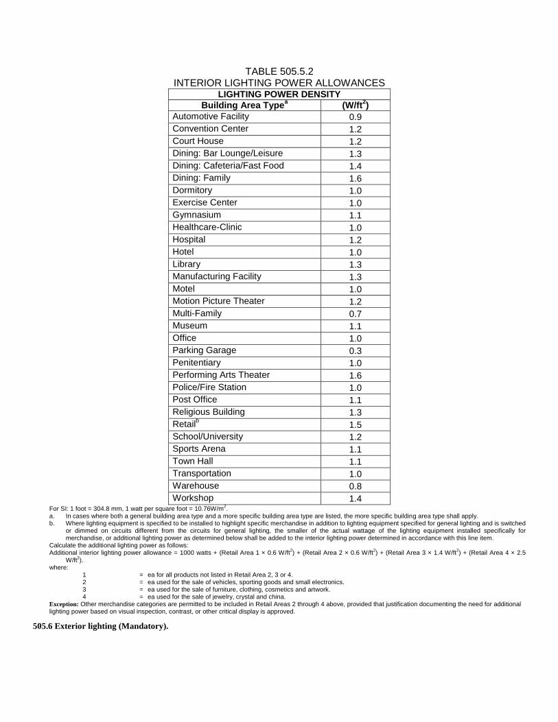
TABLE 505.5.2 INTERIOR LIGHTING POWER ALLOWANCES
LIGHTING POWER DENSITY
Building Area Typea (W/ft
2)
Automotive Facility 0.9
Convention Center 1.2
Court House 1.2
Dining: Bar Lounge/Leisure 1.3
Dining: Cafeteria/Fast Food 1.4
Dining: Family 1.6
Dormitory 1.0
Exercise Center 1.0
Gymnasium 1.1
Healthcare-Clinic 1.0
Hospital 1.2
Hotel 1.0
Library 1.3
Manufacturing Facility 1.3
Motel 1.0
Motion Picture Theater 1.2
Multi-Family 0.7
Museum 1.1
Office 1.0
Parking Garage 0.3
Penitentiary 1.0
Performing Arts Theater 1.6
Police/Fire Station 1.0
Post Office 1.1
Religious Building 1.3
Retailb 1.5
School/University 1.2
Sports Arena 1.1
Town Hall 1.1
Transportation 1.0
Warehouse 0.8
Workshop 1.4 For SI: 1 foot = 304.8 mm, 1 watt per square foot = 10.76W/m
2.
a. In cases where both a general building area type and a more specific building area type are listed, the more specific building area type shall apply. b. Where lighting equipment is specified to be installed to highlight specific merchandise in addition to lighting equipment specified for general lighting and is switched
or dimmed on circuits different from the circuits for general lighting, the smaller of the actual wattage of the lighting equipment installed specifically for merchandise, or additional lighting power as determined below shall be added to the interior lighting power determined in accordance with this line item.
Calculate the additional lighting power as follows: Additional interior lighting power allowance = 1000 watts + (Retail Area 1 × 0.6 W/ft
2) + (Retail Area 2 × 0.6 W/ft
2) + (Retail Area 3 × 1.4 W/ft
2) + (Retail Area 4 × 2.5
W/ft2).
where: Retail Area 1 = The floor area for all products not listed in Retail Area 2, 3 or 4. Retail Area 2 = The floor area used for the sale of vehicles, sporting goods and small electronics. Retail Area 3 = The floor area used for the sale of furniture, clothing, cosmetics and artwork. Retail Area 4 = The floor area used for the sale of jewelry, crystal and china. Exception: Other merchandise categories are permitted to be included in Retail Areas 2 through 4 above, provided that justification documenting the need for additional lighting power based on visual inspection, contrast, or other critical display is approved.
505.6 Exterior lighting (Mandatory).

When the power for exterior lighting is supplied through the energy service to the building, all exterior lighting, other than low-voltage
landscape lighting, shall comply with Sections 505.6.1 and 505.6.2.
Exception: Where approved because of historical, safety, signage or emergency considerations.
505.6.1 Exterior building grounds lighting.
All exterior building grounds luminaires that operate at greater than 100 watts shall contain lamps having a minimum efficacy of 60
lumens per watt unless the luminaire is controlled by a motion sensor or qualifies for one of the exceptions under Section 505.6.2.
505.6.2 Exterior building lighting power.
The total exterior lighting power allowance for all exterior building applications is the sum of the base site allowance plus the individual
allowances for areas that are to be illuminated and are permitted in Table 505.6.2(2) for the applicable lighting zone. Tradeoffs are
allowed only among exterior lighting applications listed in Table 505.6.2(2), Tradable Surfaces section. The lighting zone for the
building exterior is determined from Table 505.6.2(1) unless otherwise specified by the code enforcement official. Exterior l ighting for
all applications (except those included in the exceptions to Section 505.6.2) shall comply with the requirements of Section 505.6.1.
Exceptions: Lighting used for the following exterior applications is exempt when equipped with a control device independent of the
control of the nonexempt lighting:
1. Specialized signal, directional, and marker lighting associated with transportation;
2. Advertising signage or directional signage;
3. Integral to equipment or instrumentation and is installed by its manufacturer;
4. Theatrical purposes, including performance, stage, film production and video production;
5. Athletic playing areas;
6. Temporary lighting;
7. Industrial production, material handling, transportation sites, and associated storage areas;
8. Theme elements in theme/amusement parks; and
9. Used to highlight features of public monuments and registered historic landmark structures or buildings.
TABLE 505.6.2(1) EXTERIOR LIGHTING ZONES
LIGHTING ZONE
DESCRIPTION
1 Developed areas of national parks, state parks, forest land, and rural areas
2 Areas predominantly consisting of residential zoning, neighborhood business districts, light industrial with limited night-time use and residential mixed-use areas
3 All other areas
4 High-activity commercial districts in major metropolitan areas as designated by the local land use planning authority

TABLE 505.6.2(2) INDIVIDUAL LIGHTING POWER ALLOWANCES FOR BUILDING EXTERIORS
ZONE 1 ZONE 2 ZONE 3 ZONE 4
Base Site Allowance (Base allowance may be used in tradable or nontradable surfaces.)
500 W 600 W 750 W 1300 W
Tradable Surfaces (Lighting power densities for uncovered parking areas, building grounds, building entrances and exits, canopies and overhangs and outdoor sales areas may be traded.)
Uncovered Parking Areas
Parking areas and drives
0.04 W/ft2 0.06 W/ft
2 0.10 W/ft
2 0.13 W/ft
2
Building Grounds
Walkways less than 10 feet
wide 0.7 W/linear foot 0.7 W/linear foot 0.8 W/linear foot 1.0 W/linear foot
Walkways 10 feet wide or
greater, plaza areas special feature areas
0.14 W/ft2 0.14 W/ft
2 0.16 W/ft
2 0.2 W/ft
2
Stairways 0.75 W/ft2 1.0 W/ft
2 1.0 W/ft
2 1.0 W/ft
2
Pedestrian tunnels
0.15 W/ft2 0.15 W/ft
2 0.2 W/ft
2 0.3 W/ft
2
Building Entrances and Exits
Main entries 20 W/linear foot
of door width 20 W/linear foot
of door width 30 W/linear foot
of door width 30 W/linear foot
of door width
Other doors 20 W/linear foot
of door width 20 W/linear foot
of door width 20 W/linear foot
of door width 20 W/linear foot
of door width
Entry canopies 0.25 W/ft2 0.25 W/ft
2 0.4 W/ft
2 0.4 W/ft
2
Sales Canopies
Free-standing and attached
0.6 W/ft2 0.6 W/ft
2 0.8 W/ft
2 1.0 W/ft
2
Outdoor Sales
Open areas (including
vehicle sales lots)
0.25 W/ft2 0.25 W/ft
2 0.5 W/ft
2 0.7 W/ft
2
Street frontage for vehicle sales lots in addition to “open area”
allowance
No allowance 10 W/linear foot 10 W/linear foot 30 W/linear foot

TABLE 505.6.2(2)—continued INDIVIDUAL LIGHTING POWER ALLOWANCES FOR BUILDING EXTERIORS
ZONE 1 ZONE 2 ZONE 3 ZONE 4
Nontradable Surfaces (Lighting power density calculations for the following applications can be used only for the specific application and cannot be traded between surfaces or with other exterior lighting. The following allowances are in addition to any allowance otherwise permitted in the “Tradable Surfaces” section of this table.)
Building facades No allowance
0.1 W/ft2
for each
illuminated wall or surface
or 2.5 W/ linear foot for
each illuminated
wall or surface length
0.15 W/ft2
for each
illuminated wall or
surface or 3.75 W/
linear foot for each
illuminated wall or surface length
0.2 W/ft2
for each illuminated wall or
surface or 5.0 W/linear foot for each illuminated wall or surface
length
Automated teller machines and
night depositories
270 W per location plus 90 W per
additional ATM per location
270 W per location plus 90
W per additional ATM
per location
270 W per location plus
90 W per additional ATM per location
270 W per location plus 90 W per
additional ATM per location
Entrances and gatehouse inspection stations at guarded facilities
0.75 W/ft2 of
covered and uncovered area
0.75 W/ft2
of covered and
uncovered area
0.75 W/ft2
of covered and uncovered
area
0.75 W/ft2 of
covered and uncovered area
Loading areas for law
enforcement, fire, ambulance
and other emergency
service vehicles
0.5 W/ft2 of covered
and uncovered area
0.5 W/ft2 of
covered and uncovered area
0.5 W/ft2
of covered and uncovered
area
0.5 W/ft2 of
covered and uncovered area
Drive-up windows/doors
400 W per drive-through
400 W per drive-through
400 W per drive-
through
400 W per drive-through
Parking near 24- hour retail entrances
800 W per main entry
800 W per main entry
800 W per main entry
800 W per main entry
For SI: 1 foot = 304.8 mm, 1 watt per square foot = 10.76 W/m2, 1 watt per linear foot = W/304.8 mm.
505.7 Electrical energy consumption (Mandatory).
In buildings having individual dwelling units, provisions shall be made to determine the electrical energy consumed by each tenant by
separately metering individual dwelling units.
SECTION ECC 506
TOTAL BUILDING PERFORMANCE
506.1 Scope.
This section establishes criteria for compliance using total building performance. The following systems and loads shall be included in
determining the total building performance: heating systems, cooling systems, service water heating, fan systems, lighting power,
receptacle loads and process loads.
506.2 Mandatory requirements.
Compliance with this section requires that the criteria of Sections 502.4, 502.5, 503.2, 504, 505.2, 505.3, 505.4, 505.6 and 505.7 be met.

506.3 Performance-based compliance.
Compliance based on total building performance requires that a proposed building (proposed design) be shown to have an annual energy
cost that is less than or equal to the annual energy cost of the standard reference design. Energy prices shall be taken from a source
approved by the code enforcement official, such as the Department of Energy, Energy Information Administration’s State Energy Price and
Expenditure Report. Code enforcement officials shall be permitted to require time-of-use pricing in energy cost calculations. Nondepletable
energy collected off site shall be treated and priced the same as purchased energy. Energy from nondepletable energy sources collected on
site shall be omitted from the annual energy cost of the proposed design.
Exception: Jurisdictions that require site energy (1 kWh = 3413 Btu) rather than energy cost as the metric of comparison.
506.4 Documentation.
Documentation verifying that the methods and accuracy of compliance software tools conform to the provisions of this section shall be
provided to the code enforcement official.
506.4.1 Compliance report.
Compliance software tools shall generate a report that documents that the proposed design has annual energy costs less than or equal to
the annual energy costs of the standard reference design. The compliance documentation shall include the following information:
1. Address of the building;
2. An inspection checklist documenting the building component characteristics of the proposed design as listed in Table 506.5.1(1).
The inspection checklist shall show the estimated annual energy cost for both the standard reference design and the proposed design;
3. Name of individual completing the compliance report; and
4. Name and version of the compliance software tool.
506.4.2 Additional documentation.
The code enforcement official shall be permitted to require the following documents:
1. Documentation of the building component characteristics of the standard reference design;
2. Thermal zoning diagrams consisting of floor plans showing the thermal zoning scheme for standard reference design and proposed
design.
3. Input and output report(s) from the energy analysis simulation program containing the complete input and output files, as app licable.
The output file shall include energy use totals and energy use by energy source and end-use served, total hours that space-
conditioning loads are not met and any errors or warning messages generated by the simulation tool as applicable;
4. An explanation of any error or warning messages appearing in the simulation tool output; and
5. A certification signed by the builder providing the building component characteristics of the proposed design as given in Tab le
506.5.1(1).
506.5 Calculation procedure.
Except as specified by this section, the standard reference design and proposed design shall be configured and analyzed using identical
methods and techniques.
506.5.1 Building specifications.
The standard reference design and proposed design shall be configured and analyzed as specified by Table 506.5.1(1). Table 506.5.1(1)
shall include by reference all notes contained in Table 502.2(1).

TABLE 506.5.1(1) SPECIFICATIONS FOR THE STANDARD REFERENCE AND PROPOSED DESIGNS
In accordance with Section 506.5.1, this table includes by reference all notes contained in Table 502.2(1). BUILDING
COMPONENT CHARACTERISTICS
STANDARD REFERENCE DESIGN PROPOSED DESIGN
Space use classification
Same as proposed
The space use classification shall be chosen in accordance with Table 505.5.2 for all areas of the building covered by this permit. Where the space use classification for a building is not known, the building shall be categorized as an office building.
Roofs
Type: Insulation entirely above deck As proposed
Gross area: same as proposed As proposed
U-factor: from Table 502.1.2 As proposed
Solar absorptance: 0.75 As proposed
Emittance: 0.90 As proposed
Walls, above grade
Type: Mass wall if proposed wall is mass; otherwise steel-framed wall
As proposed
Gross area: same as proposed As proposed
U-factor: from Table 502.1.2 As proposed
Solar absorptance: 0.75 As proposed
Emittance: 0.90 As proposed
Walls, below grade
Type: Mass wall As proposed
Gross area: same as proposed As proposed
U-Factor: from Table 502.1.2 with insulation layer on interior side of walls
As proposed
Floors, above grade
Type: joist/framed floor As proposed
Gross area: same as proposed As proposed
U-factor: from Table 502.1.2 As proposed
Floors, slab on grade Type: Unheated As proposed
F-factor: from Table 502.1.2 As proposed
Doors
Type: Swinging As proposed
Area: Same as proposed As proposed
U-factor: from Table 502.2(1) As proposed
Glazing
Area: (a) The proposed glazing area; where the proposed glazing area is less than 40 percent of above-grade wall area. (b) 40 percent of above-grade wall area; where the proposed glazing area is 40 percent or more of the above-grade wall area.
As proposed
U-factor: from Table 502.3 As proposed
SHGC: from Table 502.3 except that for climates with no requirement (NR) SHGC = 0.40 shall be used
As proposed
External shading and PF: None As proposed
Skylights Area (a) The proposed skylight area; where the proposed skylight area is less
As proposed

than 3 percent of gross area of roof assembly. (b) 3 percent of gross area of roof assembly; where the proposed skylight area is 3 percent or more of gross area of roof assembly.
U-factor: from Table 502.3 As proposed
SHGC: from Table 502.3 except that for climates with no requirement (NR) SHGC = 0.40 shall be used.
As proposed
Lighting, interior
The interior lighting power shall be determined in accordance with Table 505.5.2. Where the occupancy of the building is not known, the lighting power density shall be 1.0 watt per square foot (10.73 W/m
2) based on the
categorization of buildings with unknown space classification as offices.
As proposed
Lighting, exterior
The lighting power shall be determined in accordance with Table 505.6.2. Areas and dimensions of tradable and nontradable surfaces shall be the same as proposed.
As proposed
(continued)

TABLE 506.5.1(1)—continued SPECIFICATIONS FOR THE STANDARD REFERENCE AND PROPOSED DESIGNS
BUILDING COMPONENT
CHARACTERISTICS STANDARD REFERENCE DESIGN PROPOSED DESIGN
Internal gains Same as proposed
Receptacle, motor and process loads shall be modeled and estimated based on the space use classification. All end-use load components within and associated with the building shall be modeled to include, but not be limited to, the following: exhaust fans, parking garage ventilation fans, exterior building lighting, swimming pool heaters and pumps, elevators, escalators, refrigeration equipment and cooking equipment.
Schedules Same as proposed
Operating schedules shall include hourly profiles for daily operation and shall account for variations between weekdays, weekends, holidays and any seasonal operation. Schedules shall model the time-dependent variations in occupancy, illumination, receptacle loads, thermostat settings, mechanical ventilation, HVAC equipment vailability, service hot water usage and any process loads. The schedules shall be typical of the proposed building type as determined by the designer and approved by the jurisdiction.
Mechanical ventilation Same as proposed As proposed, in accordance with Section 503.2.5.
Heating systems
Fuel type: same as proposed design
As proposed As proposed As proposed As proposed
Equipment typea: from Tables 506.5.1(2) and
506.5.1(3)
Efficiency: from Tables 503.2.3(4) and 503.2.3(5)
Capacityb: sized proportionally to the capacities
in the proposed design based on sizing runs, and shall be established such that no smaller number of unmet heating load hours and no larger heating capacity safety factors are provided than in the proposed design.
Cooling systems Fuel type: same as proposed design As proposed
Equipment typec: from Tables 506.5.1(2) and As proposed

506.5.1(3)
Efficiency: from Tables 503.2.3(1), 503.2.3(2) and 503.2.3(3)
As proposed
Capacityb: sized proportionally to the capacities
in the proposed design based on sizing runs, and shall be established such that no smaller number of unmet cooling load hours and no larger cooling capacity safety factors are provided than in the proposed design.
As proposed
Economizerd: same as proposed, in accordance
with Section 503.4.1. As proposed
Service water heating
Fuel type: same as proposed
As proposed As proposed As proposed
Efficiency: from Table 504.2
Capacity: same as proposed Where no service water hot water system exists or is specified in the proposed design, no service hot water heating shall be modeled.
For SI: 1 watt per square foot = 10.76 W/m2.
a. Where no heating system exists or has been specified, the heating system shall be modeled as fossil fuel. The system characteristics shall be identical in both the standard reference design and proposed design. b. The ratio between the capacities used in the annual simulations and the capacities determined by sizing runs shall be the same for both the standard reference design and proposed design. c. Where no cooling system exists or no cooling system has been specified, the cooling system shall be modeled as an air-cooled single-zone system, one unit per thermal zone. The system characteristics shall be identical in both the standard reference design and proposed design. d. If an economizer is required in accordance with Table 503.3.1(1), and if no economizer exists or is specified in the proposed design, then a supply-air economizer shall be provided in accordance with Section 503.4.1.
TABLE 506.5.1(2) HVAC SYSTEMS MAP
CONDENSER COOLING SOURCE
a
HEATING SYSTEM
CLASSIFICATIONb
STANDARD REFERENCE DESIGN HVC SYSTEM TYPEc
Single-zone Residential System
Single-zone Nonresidential System
All Other
Water/ground
Electric resistance System 5 System 5 System 1
Heat pump System 6 System 6 System 6
Fossil fuel System 7 System 7 System 2
Air/none
Electric resistance System 8 System 9 System 3
Heat pump System 8 System 9 System 3
Fossil fuel System 10 System 11 System 4 a. Select “water/ground” if the proposed design system condenser is water or evaporatively cooled; select “air/none” if the condenser is air cooled. Closed-circuit dry
coolers shall be considered air cooled. Systems utilizing district cooling shall be treated as if the condenser water type were “water.” If no mechanical cooling is specified or the mechanical cooling system in the proposed design does not require heat rejection, the system shall be treated as if the condenser water type were “Air.” For proposed designs with ground-source or groundwater-source heat pumps, the standard reference design HVAC system shall be water-source heat pump (System 6).
b. Select the path that corresponds to the proposed design heat source: electric resistance, heat pump (including air source and water source), or fuel fired. Systems utilizing district heating (steam or hot water) and systems with no heating capability shall be treated as if the heating system type were “fossil fuel.” For systems with mixed fuel heating sources, the system or systems that use the secondary heating source type (the one with the smallest total installed output capacity for the spaces served by the system) shall be modeled identically in the standard reference design and the primary heating source type shall be used to determine standard reference design HVAC system type.
c. Select the standard reference design HVAC system category: The system under “single-zone residential system” shall be selected if the HVAC system in the proposed design is a single-zone system and serves a residential space. The system under “single-zone nonresidential system” shall be selected if the HVAC system in the proposed design is a single-zone system and serves other than residential spaces. The system under “all other” shall be selected for all other cases.

TABLE 506.5.1(3) SPECIFICATIONS FOR THE STANDARD REFERENCE DESIGN HVAC SYSTEM DESCRIPTIONS
SYSTEM NO. SYSTEM TYPE FAN CONTROL COOLING TYPE HEATING TYPE
1 Variable air volume with parallel
fan-powered boxesa
VAVd Chilled water
e
Electric resistance
2 Variable air volume with reheat
b
VAVd Chilled water
e
Hot water fossil fuel boiler
f
3 Packaged variable air volume with parallel fan-powered boxes
a
VAVd
Direct expansion
c
Electric resistance
4 Packaged variable air volume with reheat
b
VAVd
Direct expansion
c
Hot water fossil fuel boiler
f
5 Two-pipe fan coil
Constant volumei Chilled water
e
Electric resistance
6 Water-source heat pump
Constant volumei
Direct expansion
c
Electric heat pump and boiler
g
7 Four-pipe fan coil
Constant volumei Chilled water
e
Hot water fossil fuel boiler
f
8 Packaged terminal heat pump
Constant volumei
Direct expansion
c
Electric heat pumph
9 Packaged rooftop heat pump
Constant volumei
Direct expansion
c
Electric heat pumph
10 Packaged terminal air conditioner
Constant volumei Direct expansion
Hot water fossil fuel boiler
f
11 Packaged rooftop air conditioner
Constant volumei Direct expansion
Fossil fuel furnace
For SI: 1 foot = 304.8 mm, 1 cfm = 0.0004719 m3/s, 1 Btu/h = 0.293/W, °C = [(°F -32)/1.8].
a. VAV with parallel boxes: Fans in parallel VAV fan-powered boxes shall be sized for 50 percent of the peak design flow rate and shall be modeled with 0.35 W/cfm fan power. Minimum volume setpoints for fan-powered boxes shall be equal to the minimum rate for the space required for ventilation consistent with Section 503.4.5, Exception 5. Supply-air temperature set point shall be constant at the design condition. b. VAV with reheat: Minimum volume set points for VAV reheat boxes shall be 0.4 cfm/ft
2 of floor area. Supply-air temperature shall be reset based on zone demand
from the design temperature difference to a 10°F temperature difference under minimum load conditions. Design airflow rates shall be sized for the reset supply air temperature, i.e., a 10°F temperature difference. c. Direct expansion: The fuel type for the cooling system shall match that of the cooling system in the proposed design. d. VAV: Constant volume can be modeled if the system qualifies for Section 503.4.5, Exception 1. When the proposed design system has a supply, return or relief fan motor 25 horsepower (hp) or larger, the corresponding fan in the VAV system of the standard reference design shall be modeled assuming a variable speed drive. For smaller fans, a forward-curved centrifugal fan with inlet vanes shall be modeled. If the proposed design’s system has a direct digital control system at the zone level, static pressure set point reset based on zone requirements in accordance with Section 503.4.2 shall be modeled. e. Chilled water: For systems using purchased chilled water, the chillers are not explicitly modeled and chilled water costs shall be based as determined in Sections 506.3 and 506.5.2. Otherwise, the standard reference design’s chiller plant shall be modeled with chillers having the number as indicated in Table 506.5.1(4) as a function of standard reference building chiller plant load and type as indicated in Table 506.5.1(5) as a function of individual chiller load. Where chiller fuel source is mixed, the system in the standard reference design shall have chillers with the same fuel types and with capacities having the same proportional capacity as the proposed design’s chillers for each fuel type. Chilled water supply temperature shall be modeled at 44°F design supply temperature and 56°F return temperature. Piping losses shall not be modeled in either building model. Chilled water supply water temperature shall be reset in accordance with Section 503.4.3.4. Pump system power for each pumping system shall be the same as the proposed design; if the proposed design has no chilled water pumps, the standard reference design pump power shall be 22 W/gpm (equal to a pump operating against a 75-foot head, 65-percent combined impeller and motor efficiency). The chilled water system shall be modeled as primary-only variable flow with flow maintained at the design rate through each chiller using a bypass. Chilled water pumps shall be modeled as riding the pump curve or with variable-speed drives when required in Section 503.4.3.4. The heat rejection device shall be an axial fan cooling tower with two-speed fans if required in Section 503.4.4. Condenser water design supply temperature shall be 85°F or 10°F approach to design wet-bulb temperature, which-ever is lower, with a design temperature rise of 10°F. The tower shall be controlled to maintain a 70°F leaving water temperature where weather permits, floating up to leaving water temperature at design conditions. Pump system power for each pumping system shall be the same as the proposed design; if the proposed design has no condenser water pumps, the standard reference design pump power shall be 19 W/gpm (equal to a pump operating against a 60-foot head, 60-percent combined impeller and motor efficiency). Each chiller shall be modeled with separate condenser water and chilled water pumps interlocked to operate with the associated chiller. f. Fossil fuel boiler: For systems using purchased hot water or steam, the boilers are not explicitly modeled and hot water or steam costs shall be based on actual utility rates. Otherwise, the boiler plant shall use the same fuel as the proposed design and shall be natural draft. The standard reference design boiler plant shall be modeled with a single boiler if the standard reference design plant load is 600,000 Btu/h and less and with two equally sized boilers for plant capacities exceeding 600,000 Btu/h. Boilers shall be staged as required by the load. Hot water supply temperature shall be modeled at 180°F design supply temperature and 130°F return temperature. Piping losses shall not be modeled in either building model. Hot water supply water temperature shall be reset in accordance with Section 503.4.3.4. Pump system power for each pumping system shall be the same as the proposed design; if the proposed design has no hot water pumps, the standard reference design pump power shall be 19 W/gpm (equal to a pump operating against a 60-foot head, 60-percent combined impeller and motor efficiency). The hot water system shall be modeled as primary only with continuous variable flow. Hot water pumps shall be modeled as riding the pump curve or with variable speed drives when required by Section 503.4.3.4. g. Electric heat pump and boiler: Water-source heat pumps shall be connected to a common heat pump water loop controlled to maintain temperatures between 60°F and 90°F. Heat rejection from the loop shall be provided by an axial fan closed-circuit evaporative fluid cooler with two-speed fans if required in Section 503.4.2. Heat addition to the loop shall be provided by a boiler that uses the same fuel as the proposed design and shall be natural draft. If no boilers exist in the proposed design, the standard reference building boilers shall be fossil fuel. The standard reference design boiler plant shall be modeled with a single boiler if the standard reference design plant load is 600,000 Btu/h or less and with two equally sized boilers for plant capacities exceeding 600,000 Btu/h. Boilers shall be staged as required

by the load. Piping losses shall not be modeled in either building model. Pump system power shall be the same as the proposed design; if the proposed design has no pumps, the standard reference design pump power shall be 22 W/gpm, which is equal to a pump operating against a 75-foot head, with a 65-percent combined impeller and motor efficiency. Loop flow shall be variable with flow shutoff at each heat pump when its compressor cycles off as required by Section 503.4.3.3. Loop pumps shall be modeled as riding the pump curve or with variable speed drives when required by Section 503.4.3.4. h. Electric heat pump: Electric air-source heat pumps shall be modeled with electric auxiliary heat. The system shall be controlled with a multistage space thermostat and an outdoor air thermostat wired to energize auxiliary heat only on the last thermostat stage and when outdoor air temperature is less than 40°F. i. Constant volume: Fans shall be controlled in the same manner as in the proposed design; i.e., fan operation whenever the space is occupied or fan operation
cycled on calls for heating and cooling. If the fan is modeled as cycling and the fan energy is included in the energy efficiency rating of the equipment, fan energy shall not be modeled explicitly.
TABLE 506.5.1(4) NUMBER OF CHILLERS
TOTAL CHILLER PLANT CAPACITY NUMBER OF CHILLERS
300 tons 1
> 300 tons, < 600 tons 2, sized equally
600 tons 2 minimum, with chillers added so that no chiller is
larger than 800 tons, all sized equally For SI: 1 ton = 3517 W.
TABLE 506.5.1(5) WATER CHILLER TYPES
INDIVIDUAL CHILLER PLANT CAPACITY
ELECTRIC CHILLER TYPE
FOSSIL FUEL CHILLER TYPE
100 tons Reciprocating Single-effect absorption, direct fired
> 100 tons, < 300 tons Screw Double-effect absorption, direct fired
300 tons Centrifugal Double-effect absorption, direct fired For SI: 1 ton = 3517 W.
506.5.2 Thermal blocks.
The standard reference design and proposed design shall be analyzed using identical thermal blocks as required in Section 506.5.2.1,
506.2.2 or 506.5.2.3.
506.5.2.1 HVAC zones designed.
Where HVAC zones are defined on HVAC design drawings, each HVAC zone shall be modeled as a separate thermal block.
Exception: Different HVAC zones shall be allowed to be combined to create a single thermal block or identical thermal blocks to
which multipliers are applied, provided:
1. The space use classification is the same throughout the thermal block.
2. All HVAC zones in the thermal block that are adjacent to glazed exterior walls face the same orientation or their orientations
are within 45 degrees (0.79 rad) of each other.
3. All of the zones are served by the same HVAC system or by the same kind of HVAC system.
506.5.2.2 HVAC zones not designed.
Where HVAC zones have not yet been designed, thermal blocks shall be defined based on similar internal load densities, occupancy,
lighting, thermal and temperature schedules, and in combination with the following guidelines:
1. Separate thermal blocks shall be assumed for interior and perimeter spaces. Interior spaces shall be those located more than 15 feet
(4572 mm) from an exterior wall. Perimeter spaces shall be those located closer than 15 feet (4572 mm) from an exterior wall.
2. Separate thermal blocks shall be assumed for spaces adjacent to glazed exterior walls: a separate zone shall be provided for each
orientation, except orientations that differ by no more than 45 degrees (0.79 rad) shall be permitted to be considered to be the
same orientation. Each zone shall include floor area that is 15 feet (4572 mm) or less from a glazed perimeter wall, except that
floor area within 15 feet (4572 mm) of glazed perimeter walls having more than one orientation shall be divided proportionately
between zones.
3. Separate thermal blocks shall be assumed for spaces having floors that are in contact with the ground or exposed to ambient
conditions from zones that do not share these features.

4. Separate thermal blocks shall be assumed for spaces having exterior ceiling or roof assemblies from zones that do not share these
features.
506.5.2.3 Multifamily residential buildings.
Residential spaces shall be modeled using one thermal block per space except that those facing the same orientations are permitted to
be combined into one thermal block. Corner units and units with roof or floor loads shall only be combined with units sharing these
features.
506.6 Calculation software tools.
Calculation procedures used to comply with this section shall be software tools capable of calculating the annual energy consumption of all
building elements that differ between the standard reference design and the proposed design and shall include the following capabilities.
1. Computer generation of the standard reference design using only the input for the proposed design. The calculation procedure shall not
allow the user to directly modify the building component characteristics of the standard reference design.
2. Building operation for a full calendar year (8760 hours).
3. Climate data for a full calendar year (8760 hours) and shall reflect approved coincident hourly data for temperature, solar radiation,
humidity and wind speed for the building location.
4. Ten or more thermal zones.
5. Thermal mass effects.
6. Hourly variations in occupancy, illumination, receptacle loads, thermostat settings, mechanical ventilation, HVAC equipment
availability, service hot water usage and any process loads.
7. Part-load performance curves for mechanical equipment.
8. Capacity and efficiency correction curves for mechanical heating and cooling equipment.
9. Printed code enforcement official inspection checklist listing each of the proposed design component characteristics from Table
506.5.1(1) determined by the analysis to provide compliance, along with their respective performance ratings (e.g., R-value, U-factor,
SHGC, HSPF, AFUE, SEER, EF, etc.).
506.6.1 Specific approval.
Performance analysis tools meeting the applicable subsections of Section 506 and tested according to ASHRAE Standard 140 shal l be
permitted to be approved. Tools are permitted to be approved based on meeting a specified threshold for a jurisdiction. The code
enforcement official shall be permitted to approve tools for a specified application or limited scope.
506.6.2 Input values.
When calculations require input values not specified by Sections 502, 503, 504 and 505, those input values shall be taken from an
approved source.