commercial heat-tracing - nventthermal.ie · local requirements applicable to electric heat-tracing...
TRANSCRIPT
InstallatIon and MaIntenance Manualself-RegulatIng HeatIng cable systeMs
Commercial heat-tracing
Raychem-IM-CDE1547-HeatTracingCOM-EN-1706Thermal managemenT
1 general information 1
2 Product data 2
3 heating cable selection 6
4 heating cable storage 6
5 Product checks 7
6 Components installation 11
7 Controls, thermal insulation and marking 13
8 Power supply and electrical connection 15
9 heating cable testing 16
10 Operation, maintenance and pipe repairs 17
11 heating cable damage 18
1 general infOrmaTiOn
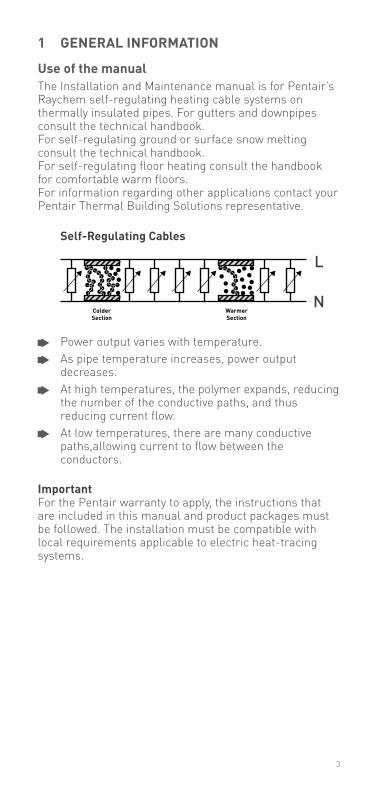
Use of the manualThe Installation and Maintenance manual is for Pentair’s Raychem self-regulating heating cable systems on thermally insulated pipes. For gutters and downpipes consult the technical handbook. For self-regulating ground or surface snow melting consult the technical handbook.For self-regulating floor heating consult the handbook for comfortable warm floors.For information regarding other applications contact your Pentair Thermal Building Solutions representative.
Self-regulating Cables
Power output varies with temperature. As pipe temperature increases, power output
decreases. At high temperatures, the polymer expands, reducing
the number of the conductive paths, and thus reducing current flow.
At low temperatures, there are many conductive paths,allowing current to flow between the conductors.
importantFor the Pentair warranty to apply, the instructions that are included in this manual and product packages must be followed. The installation must be compatible with local requirements applicable to electric heat-tracing systems.
ColderSection
WarmerSection
L
N
3
2 PrOdUCT daTa
Warning
as with any electrical equipment or wiring installation operating at line voltages, heating cable and component damage or incorrect installation that allows the penetration of moisture or contamination can lead to electrical tracking, arcing and potential fire hazard.
Cable type hWaT-l hWaT-m hWaT-r fS-a-2X fS-B-2X fS-C-2X fS-C10-2X
Hot water temperature maintenance
Pipe Freeze Protection Pipe Freeze Protection/ Temperature maintenance
Pipe Freeze Protection for LPHW services
nominal voltage 230 VAC 230 VAC 230 VAC 230 VAC 230 VAC 230 VAC 230 VAC
nominal power output (*on insulated metal pipes)
7 W/m at 45°C
9 W/m at 55°C
12 W/m at 70°C
10 W/m at 5°C 26 W/m at 5°C 31 W/m at 5°C 22 W/m at 40°C
10 W/m at 5°C
C-type circuit-breaker according to selected kit
max. 20 A max. 20 A max. 20 A max. 16 A max. 16 A max. 16 A max. 25 A
max. circuit length 180 m 20 A
100 m 20 A
100 m 20 A
150 m 16 A
105 m16 A
90 m16 A
180 m20 A
min. bending radius 10 mm 10 mm 10 mm 10 mm 10 mm 10 mm 10 mm
max. continous expo-sure temperature
65°C 65°C 80°C 65°C 65°C 95°C 90°C
max. exposure tem-perature (power-on condition – 800 h. cumulative)
85°C 85°C 90°C 85°C 85°C 95°C 90°C
max. dimensions in mm (W x h)
13.8 x 6.8 13.7 x 7.6 16.1 x 6.7 13.7 x 6.2 13.7 x 6.2 12.7 x 5.3 16 x 6.8
Weight 0.12 kg/m 0.12 kg/m 0.14 kg/m 0.13 kg/m 0.13 kg/m 0.13 kg/m 0.14 kg/m
approvals/Certification BS / ÖVE / VDE / SEV / CSTB / SVGW / EAC / UKrSEPRO DVGW / CE / VDE / EAC / UKrSEPRO
Control units HWAT-T55 HWAT-ECO
HWAT-ECO HWAT-ECO AT-TS-13AT-TS-14RAySTAT- CONTROL-10 RAySTAT-ECORAySTAT- CONTROL-11-DIN
AT-TS-13AT-TS-14RAySTAT- CONTROL-10 RAySTAT-ECORAySTAT- CONTROL-11-DIN
AT-TS-13AT-TS-14RAySTAT- CONTROL-10 RAySTAT- CONTROL-11-DIN
AT-TS-13*AT-TS-14*RAySTAT- CONTROL-10RAySTAT-ECO-10RAySTAT- CONTROL-11-DIN**maximum circuit of 150m
Connection system
Junction box – – – – – JB16-02 JB16-02
Connection and end seal
RayClic RayClic RayClic RayClic RayClic CE20-01 CE20-01CE25-21
Support bracket included in the kit
included in the kit
included in the kit included in the kit
included in the kit
JB-SB-08 JB-SB-08
4
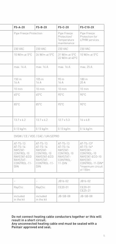
do not connect heating cable conductors together or this will result in a short circuit.any unconnected heating cable end must be sealed with a Pentair approved end seal.
Cable type hWaT-l hWaT-m hWaT-r fS-a-2X fS-B-2X fS-C-2X fS-C10-2X
Hot water temperature maintenance
Pipe Freeze Protection Pipe Freeze Protection/ Temperature maintenance
Pipe Freeze Protection for LPHW services
nominal voltage 230 VAC 230 VAC 230 VAC 230 VAC 230 VAC 230 VAC 230 VAC
nominal power output (*on insulated metal pipes)
7 W/m at 45°C
9 W/m at 55°C
12 W/m at 70°C
10 W/m at 5°C 26 W/m at 5°C 31 W/m at 5°C 22 W/m at 40°C
10 W/m at 5°C
C-type circuit-breaker according to selected kit
max. 20 A max. 20 A max. 20 A max. 16 A max. 16 A max. 16 A max. 25 A
max. circuit length 180 m 20 A
100 m 20 A
100 m 20 A
150 m 16 A
105 m16 A
90 m16 A
180 m20 A
min. bending radius 10 mm 10 mm 10 mm 10 mm 10 mm 10 mm 10 mm
max. continous expo-sure temperature
65°C 65°C 80°C 65°C 65°C 95°C 90°C
max. exposure tem-perature (power-on condition – 800 h. cumulative)
85°C 85°C 90°C 85°C 85°C 95°C 90°C
max. dimensions in mm (W x h)
13.8 x 6.8 13.7 x 7.6 16.1 x 6.7 13.7 x 6.2 13.7 x 6.2 12.7 x 5.3 16 x 6.8
Weight 0.12 kg/m 0.12 kg/m 0.14 kg/m 0.13 kg/m 0.13 kg/m 0.13 kg/m 0.14 kg/m
approvals/Certification BS / ÖVE / VDE / SEV / CSTB / SVGW / EAC / UKrSEPRO DVGW / CE / VDE / EAC / UKrSEPRO
Control units HWAT-T55 HWAT-ECO
HWAT-ECO HWAT-ECO AT-TS-13AT-TS-14RAySTAT- CONTROL-10 RAySTAT-ECORAySTAT- CONTROL-11-DIN
AT-TS-13AT-TS-14RAySTAT- CONTROL-10 RAySTAT-ECORAySTAT- CONTROL-11-DIN
AT-TS-13AT-TS-14RAySTAT- CONTROL-10 RAySTAT- CONTROL-11-DIN
AT-TS-13*AT-TS-14*RAySTAT- CONTROL-10RAySTAT-ECO-10RAySTAT- CONTROL-11-DIN**maximum circuit of 150m
Connection system
Junction box – – – – – JB16-02 JB16-02
Connection and end seal
RayClic RayClic RayClic RayClic RayClic CE20-01 CE20-01CE25-21
Support bracket included in the kit
included in the kit
included in the kit included in the kit
included in the kit
JB-SB-08 JB-SB-08
5
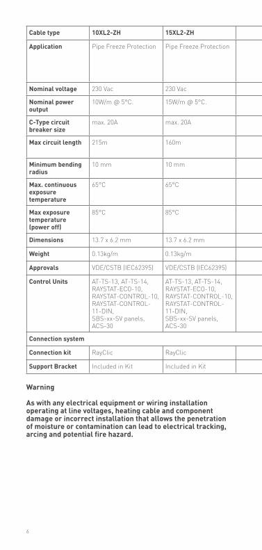
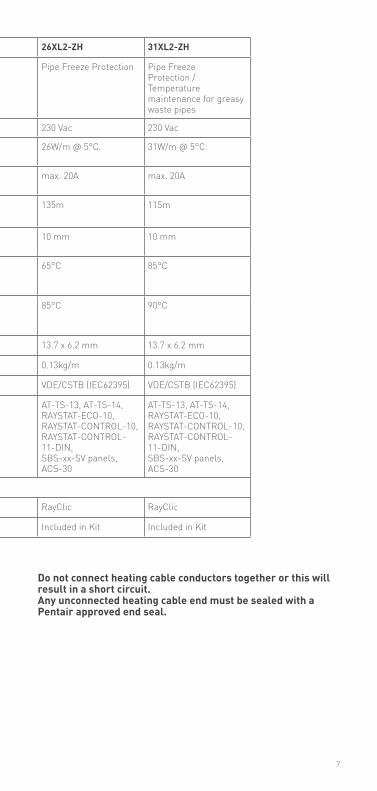
Cable type 10Xl2-Zh 15Xl2-Zh 26Xl2-Zh 31Xl2-Zh
application Pipe Freeze Protection Pipe Freeze Protection Pipe Freeze Protection Pipe Freeze Protection / Temperature maintenance for greasy waste pipes
nominal voltage 230 Vac 230 Vac 230 Vac 230 Vac
nominal power output
10W/m @ 5°C. 15W/m @ 5°C. 26W/m @ 5°C. 31W/m @ 5°C.
C-Type circuit breaker size
max. 20A max. 20A max. 20A max. 20A
max circuit length 215m 160m 135m 115m
minimum bending radius
10 mm 10 mm 10 mm 10 mm
max. continuous exposure temperature
65°C 65°C 65°C 85°C
max exposure temperature (power off)
85°C 85°C 85°C 90°C
dimensions 13.7 x 6.2 mm 13.7 x 6.2 mm 13.7 x 6.2 mm 13.7 x 6.2 mm
Weight 0.13kg/m 0.13kg/m 0.13kg/m 0.13kg/m
approvals VDE/CSTB (IEC62395) VDE/CSTB (IEC62395) VDE/CSTB (IEC62395) VDE/CSTB (IEC62395)
Control Units AT-TS-13, AT-TS-14, RAySTAT-ECO-10, RAySTAT-CONTROL-10, RAySTAT-CONTROL-11-DIN, SBS-xx-SV panels, ACS-30
AT-TS-13, AT-TS-14, RAySTAT-ECO-10, RAySTAT-CONTROL-10, RAySTAT-CONTROL-11-DIN, SBS-xx-SV panels, ACS-30
AT-TS-13, AT-TS-14, RAySTAT-ECO-10, RAySTAT-CONTROL-10, RAySTAT-CONTROL-11-DIN, SBS-xx-SV panels, ACS-30
AT-TS-13, AT-TS-14, RAySTAT-ECO-10, RAySTAT-CONTROL-10, RAySTAT-CONTROL-11-DIN, SBS-xx-SV panels, ACS-30
Connection system
Connection kit RayClic RayClic RayClic RayClic
Support Bracket Included in Kit Included in Kit Included in Kit Included in Kit
Warning
as with any electrical equipment or wiring installation operating at line voltages, heating cable and component damage or incorrect installation that allows the penetration of moisture or contamination can lead to electrical tracking, arcing and potential fire hazard.
6
Cable type 10Xl2-Zh 15Xl2-Zh 26Xl2-Zh 31Xl2-Zh
application Pipe Freeze Protection Pipe Freeze Protection Pipe Freeze Protection Pipe Freeze Protection / Temperature maintenance for greasy waste pipes
nominal voltage 230 Vac 230 Vac 230 Vac 230 Vac
nominal power output
10W/m @ 5°C. 15W/m @ 5°C. 26W/m @ 5°C. 31W/m @ 5°C.
C-Type circuit breaker size
max. 20A max. 20A max. 20A max. 20A
max circuit length 215m 160m 135m 115m
minimum bending radius
10 mm 10 mm 10 mm 10 mm
max. continuous exposure temperature
65°C 65°C 65°C 85°C
max exposure temperature (power off)
85°C 85°C 85°C 90°C
dimensions 13.7 x 6.2 mm 13.7 x 6.2 mm 13.7 x 6.2 mm 13.7 x 6.2 mm
Weight 0.13kg/m 0.13kg/m 0.13kg/m 0.13kg/m
approvals VDE/CSTB (IEC62395) VDE/CSTB (IEC62395) VDE/CSTB (IEC62395) VDE/CSTB (IEC62395)
Control Units AT-TS-13, AT-TS-14, RAySTAT-ECO-10, RAySTAT-CONTROL-10, RAySTAT-CONTROL-11-DIN, SBS-xx-SV panels, ACS-30
AT-TS-13, AT-TS-14, RAySTAT-ECO-10, RAySTAT-CONTROL-10, RAySTAT-CONTROL-11-DIN, SBS-xx-SV panels, ACS-30
AT-TS-13, AT-TS-14, RAySTAT-ECO-10, RAySTAT-CONTROL-10, RAySTAT-CONTROL-11-DIN, SBS-xx-SV panels, ACS-30
AT-TS-13, AT-TS-14, RAySTAT-ECO-10, RAySTAT-CONTROL-10, RAySTAT-CONTROL-11-DIN, SBS-xx-SV panels, ACS-30
Connection system
Connection kit RayClic RayClic RayClic RayClic
Support Bracket Included in Kit Included in Kit Included in Kit Included in Kit
do not connect heating cable conductors together or this will result in a short circuit.any unconnected heating cable end must be sealed with a Pentair approved end seal.
7
Warningas with any electrical equipment or wiring installation operating at line voltages, heating cable and component damage or incorrect installation that allows the penetration of moisture or contamination can lead to electrical tracking, arcing and potential fire hazard.
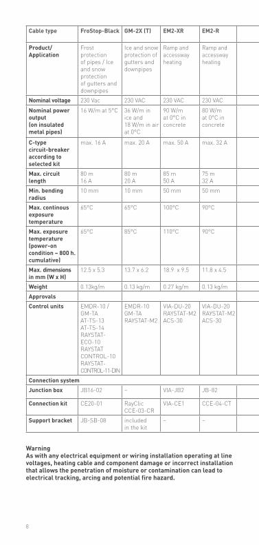
Cable type froStop-Black gm-2X (T) em2-Xr em2-r r-eTl-a r-eTl-B r-eTl-a-Cr r-eTl-B-Cr
Product/ application
Frost protectionof pipes / Ice and snow protectionof gutters anddownpipes
Ice and snow protection of gutters and downpipes
Ramp and accessway heating
Ramp and accessway heating
Frost protection for pipes
Frost Protection for pipes
Frost Protection for pipes
Frost Protection for pipes
nominal voltage 230 Vac 230 VAC 230 VAC 230 VAC 230 VAC 230 VAC 230 VAC 230 VACnominal power output (on insulated metal pipes)
16 W/m at 5°C 36 W/m in ice and 18 W/m in air at 0°C
90 W/m at 0°C in concrete
80 W/m at 0°C in concrete
10 W/m at 5°C on pipe
16W/m at 5DegC on pipe.
10W/m at 5DegC on pipe.
16W/m at 5DegC on pipe.
C-type circuit-breaker according to selected kit
max. 16 A max. 20 A max. 50 A max. 32 A max. 10 A max. 16A max. 10A max. 16A
max. circuit length
80 m16 A
80 m20 A
85 m50 A
75 m32 A
100 m10 A
100 m16A
100 m 10A
100 m16A
min. bending radius
10 mm 10 mm 50 mm 50 mm 10 mm 10 mm 10 mm 10 mm
max. continous exposure temperature
65°C 65°C 100°C 90°C 65°C 65°C 65°C 65°C
max. exposure temperature (power-on condition – 800 h. cumulative)
65°C 85°C 110°C 90°C 65°C 65°C 65°C 65°C
max. dimensions in mm (W x h)
12.5 x 5.3 13.7 x 6.2 18.9 x 9.5 11.8 x 4.5 8.5 x 5.8 8.5 x 5.8 8.5 x 5.8 8.5 x 5.8
Weight 0.13kg/m 0.13 kg/m 0.27 kg/m 0.13 kg/m 0.07 kg/m 0.07kg/m 0.07kg/m 0.07kg/mapprovals CEControl units EMDR-10 /
GM-TAAT-TS-13AT-TS-14RAySTAT-ECO-10RAySTAT CONTROL-10RAySTAT- CONTROL-11-DIN
EMDR-10GM-TARAySTAT-M2
VIA-DU-20RAySTAT-M2ACS-30
VIA-DU-20RAySTAT-M2ACS-30
AT-TS-13AT-TS-14RAySTAT- CONTROL-10 RAySTAT-ECORAySTAT- CONTROL-11-DIN
SBS-R-FP control panels
AT-TS-13AT-TS-14RAySTAT-ECO-10RAySTAT- CONTROL-10RAySTAT- CONTROL-11-DINSBS-R-FP Panels
T-TS-13AT-TS-14RAySTAT-ECO-10RAySTAT- CONTROL-10RAySTAT- CONTROL-11-DINSBS-R-FP Panels
AT-TS-13AT-TS-14RAySTAT-ECO-10RAySTAT- CONTROL-10RAySTAT- CONTROL-11-DINSBS-R-FP Panels
Connection systemJunction box JB16-02 – VIA-JB2 JB-82 JB16-02 JB16-02 JB16-02 JB16-02
Connection kit CE20-01 RayClicCCE-03-CR
VIA-CE1 CCE-04-CT CE-ETL/T2Red CE-ETL/T2RedU-ACC-PP-07
CE20-03 CE20-03
Support bracket JB-SB-08 included in the kit
– – –
8

do not connect heating cable conductors together or this will result in a short circuit.any unconnected heating cable end must be sealed with a Pentair approved end seal.
Cable type froStop-Black gm-2X (T) em2-Xr em2-r r-eTl-a r-eTl-B r-eTl-a-Cr r-eTl-B-Cr
Product/ application
Frost protectionof pipes / Ice and snow protectionof gutters anddownpipes
Ice and snow protection of gutters and downpipes
Ramp and accessway heating
Ramp and accessway heating
Frost protection for pipes
Frost Protection for pipes
Frost Protection for pipes
Frost Protection for pipes
nominal voltage 230 Vac 230 VAC 230 VAC 230 VAC 230 VAC 230 VAC 230 VAC 230 VACnominal power output (on insulated metal pipes)
16 W/m at 5°C 36 W/m in ice and 18 W/m in air at 0°C
90 W/m at 0°C in concrete
80 W/m at 0°C in concrete
10 W/m at 5°C on pipe
16W/m at 5DegC on pipe.
10W/m at 5DegC on pipe.
16W/m at 5DegC on pipe.
C-type circuit-breaker according to selected kit
max. 16 A max. 20 A max. 50 A max. 32 A max. 10 A max. 16A max. 10A max. 16A
max. circuit length
80 m16 A
80 m20 A
85 m50 A
75 m32 A
100 m10 A
100 m16A
100 m 10A
100 m16A
min. bending radius
10 mm 10 mm 50 mm 50 mm 10 mm 10 mm 10 mm 10 mm
max. continous exposure temperature
65°C 65°C 100°C 90°C 65°C 65°C 65°C 65°C
max. exposure temperature (power-on condition – 800 h. cumulative)
65°C 85°C 110°C 90°C 65°C 65°C 65°C 65°C
max. dimensions in mm (W x h)
12.5 x 5.3 13.7 x 6.2 18.9 x 9.5 11.8 x 4.5 8.5 x 5.8 8.5 x 5.8 8.5 x 5.8 8.5 x 5.8
Weight 0.13kg/m 0.13 kg/m 0.27 kg/m 0.13 kg/m 0.07 kg/m 0.07kg/m 0.07kg/m 0.07kg/mapprovals CEControl units EMDR-10 /
GM-TAAT-TS-13AT-TS-14RAySTAT-ECO-10RAySTAT CONTROL-10RAySTAT- CONTROL-11-DIN
EMDR-10GM-TARAySTAT-M2
VIA-DU-20RAySTAT-M2ACS-30
VIA-DU-20RAySTAT-M2ACS-30
AT-TS-13AT-TS-14RAySTAT- CONTROL-10 RAySTAT-ECORAySTAT- CONTROL-11-DIN
SBS-R-FP control panels
AT-TS-13AT-TS-14RAySTAT-ECO-10RAySTAT- CONTROL-10RAySTAT- CONTROL-11-DINSBS-R-FP Panels
T-TS-13AT-TS-14RAySTAT-ECO-10RAySTAT- CONTROL-10RAySTAT- CONTROL-11-DINSBS-R-FP Panels
AT-TS-13AT-TS-14RAySTAT-ECO-10RAySTAT- CONTROL-10RAySTAT- CONTROL-11-DINSBS-R-FP Panels
Connection systemJunction box JB16-02 – VIA-JB2 JB-82 JB16-02 JB16-02 JB16-02 JB16-02
Connection kit CE20-01 RayClicCCE-03-CR
VIA-CE1 CCE-04-CT CE-ETL/T2Red CE-ETL/T2RedU-ACC-PP-07
CE20-03 CE20-03
Support bracket JB-SB-08 included in the kit
– – –
9
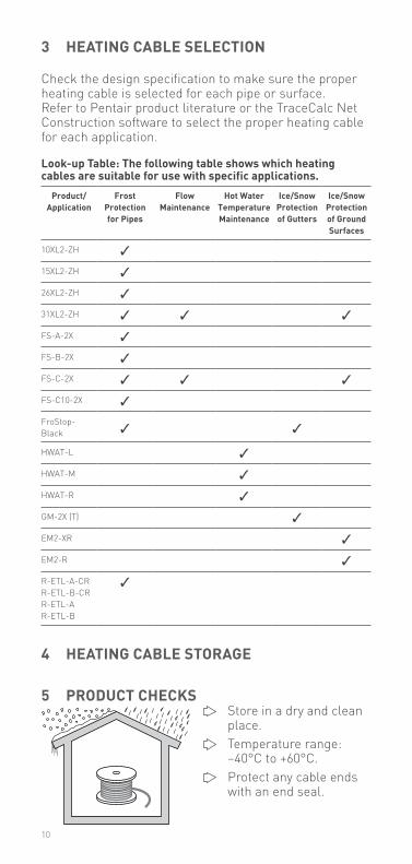
3 heaTing CaBle SeleCTiOn
Check the design specification to make sure the properheating cable is selected for each pipe or surface. Refer to Pentair product literature or the TraceCalc Net Construction software to select the proper heating cable for each application.
look-up Table: The following table shows which heating cables are suitable for use with specific applications.
Product/application
frost Protection for Pipes
flow maintenance
hot Water Temperature maintenance
ice/Snow Protection of gutters
ice/Snow Protection of ground Surfaces
10XL2-ZH
15XL2-ZH
26XL2-ZH
31XL2-ZH
FS-A-2X
FS-B-2X
FS-C-2X
FS-C10-2X
FroStop-Black
HWAT-L
HWAT-M
HWAT-R
GM-2X (T)
EM2-XR
EM2-R
R-ETL-A-CRR-ETL-B-CRR-ETL-AR-ETL-B
4 heaTing CaBle STOrage
5 PrOdUCT CheCkS Store in a dry and clean
place. Temperature range:
–40°C to +60°C. Protect any cable ends
with an end seal.
10
5.1 Pre-installation checksCheck materials received: Review the heating cable design and compare
the list of materials to the catalogue numbers of heating cables and electrical components received to confirm that proper materials are on site. The heating cable type is printed on its outer jacket.
Temperature exposure must not exceed that specified in Pentair’ product literature. Exceeding these limits will impair product performance. Check that expected exposure is within these limits.
Ensure that the heating cable voltage rating is suitable for the service voltage available.
Do not energize cable when it is coiled or on the reel. Inspect heating cable and components for in-transit
damage. An insulation resistance test (Section 9) on each reel is recommended.
Check piping to be traced: Ensure all pressure testing is complete and pipework
has final paint coating. Walk the system and plan the routing of the heating
cable on the pipe. Check pipework against specification drawing. If
different consult design authority. Inspect piping for burrs, rough surfaces, sharp
edges etc. which could damage the heating cable. Smooth off or cover with layers of glass cloth tape or aluminium foil.
11
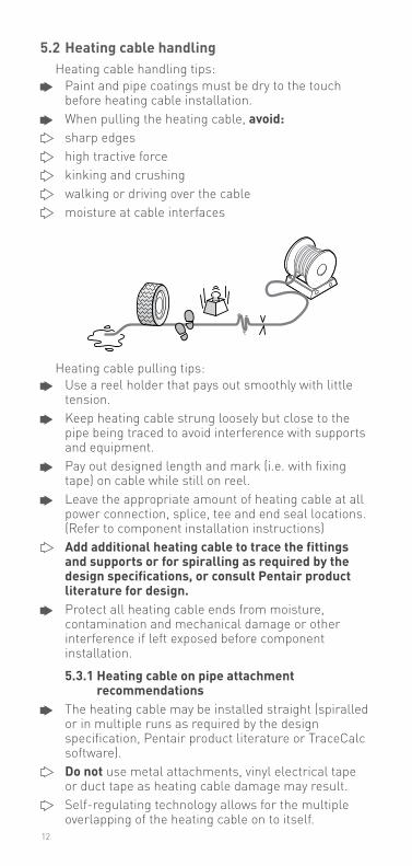
5.2 heating cable handlingHeating cable handling tips: Paint and pipe coatings must be dry to the touch
before heating cable installation. When pulling the heating cable, avoid: sharp edges high tractive force kinking and crushing walking or driving over the cable moisture at cable interfaces
Heating cable pulling tips: Use a reel holder that pays out smoothly with little
tension. Keep heating cable strung loosely but close to the
pipe being traced to avoid interference with supports and equipment.
Pay out designed length and mark (i.e. with fixing tape) on cable while still on reel.
Leave the appropriate amount of heating cable at all power connection, splice, tee and end seal locations. (Refer to component installation instructions)
add additional heating cable to trace the fittings and supports or for spiralling as required by the design specifications, or consult Pentair product literature for design.
Protect all heating cable ends from moisture, contamination and mechanical damage or other interference if left exposed before component installation.
5.3.1 heating cable on pipe attachment recommendations
The heating cable may be installed straight (spiralled or in multiple runs as required by the design specification, Pentair product literature or TraceCalc software).
do not use metal attachments, vinyl electrical tape or duct tape as heating cable damage may result.
Self-regulating technology allows for the multiple overlapping of the heating cable on to itself.
12
5.3.2 heating cable, non-pipe fixing recommendations
For snow and ice protection applications, the heating cable should be fixed in place using one of the Pentair recommended fixing methods, including spacer rail or connection to a reinforcement grid.
For gutter applications, the heater should be held in place within the gutter using recommended fixing clips as supplied by the manufacturer.
For underfloor heating applications, the heater shall be installed using the fixing methods of the manufacture or installed in the T2Reflecta heat reflector product.
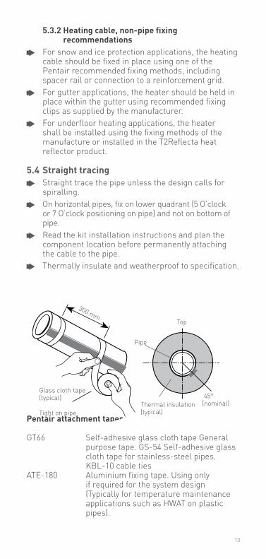
5.4 Straight tracing Straight trace the pipe unless the design calls for
spiralling. On horizontal pipes, fix on lower quadrant (5 O’clock
or 7 O’clock positioning on pipe) and not on bottom of pipe.
Read the kit installation instructions and plan the component location before permanently attaching the cable to the pipe.
Thermally insulate and weatherproof to specification.
Pentair attachment tapes:
GT66 Self-adhesive glass cloth tape General purpose tape. GS-54 Self-adhesive glass cloth tape for stainless-steel pipes. KBL-10 cable tiesATE-180 Aluminium fixing tape. Using only
if required for the system design (Typically for temperature maintenance applications such as HWAT on plastic pipes).
Glass cloth tape (typical)
Tight on pipe
Top
Pipe
Thermal insulation (typical)
45° (nominal)
300 mm
13
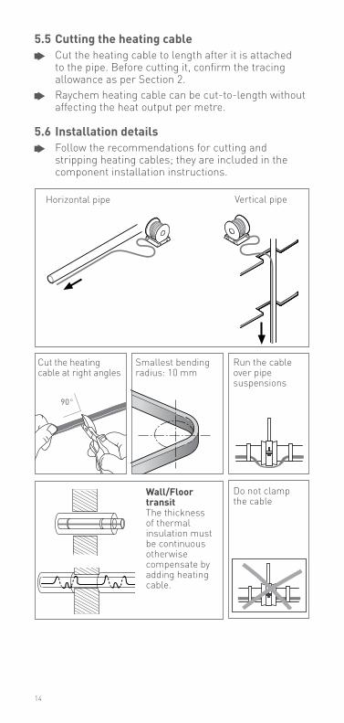
5.5 Cutting the heating cable Cut the heating cable to length after it is attached
to the pipe. Before cutting it, confirm the tracing allowance as per Section 2.
Raychem heating cable can be cut-to-length without affecting the heat output per metre.
5.6 installation details Follow the recommendations for cutting and
stripping heating cables; they are included in the component installation instructions.
Smallest bending radius: 10 mm
Horizontal pipe Vertical pipe
90°
Cut the heating cable at right angles
Do not clamp the cable
Wall/floor transitThe thickness of thermal insulation must be continuous otherwise compensate by adding heating cable.
Run the cable over pipe suspensions
14
6 COmPOnenTS inSTallaTiOn
general notes:Select the required components from Pentair product literature or use the TraceCalc Net Construction software. Raychem component kits (including power connections, splices and end seals) must be used to satisfy Standards and Approval Body requirements.Installation instructions included in the kit must be followed, including those for preparation of the heatingcable conductors for connections. Before assembly, use the guide given in the instructions to ensure that the kit iscorrect for the heating cable and environment.
Raychem self-regulating and power-limiting heating cables are parallel circuit design. Do not twist the conductors together as this will result in a short circuit.
6.1 Components required For the installation of all components refer to the
relevant component installation instructions. Required for each heating cable run:
Power connection and end-seal. As required:
Splice Tee-splice: RayClic or junction box, three connection kits and three insulation entry kits, depending on heater. Accessories (pipe straps, fixing tape, support brackets, labels, etc)
15
6.2 Component installation hints Locate RayClic / junction boxes for easy access but
not exposed to mechanical abuse. Position junction boxes so that power cable and
heating cable entries do not point upwards. Fix lids in place where access not required. Confirm junction box stopping plugs are correct for
application and fixed firmly in place. Route heating cable from RayClic / junction box to
insulation entry so as to avoid possible mechanical damage.
do not strain heating cable as it exits/enters RayClic / junction boxes and insulation entries.
Ensure heating cable is fixed above pipe straps such as used for RayClic / junction box support brackets.
Fix all low profile components (e.g. heatshrink end seals) in place.
16
7 Thermal inSUlaTiOn and marking
7.1 Pre-insulation checks Visually inspect the heating cable and components
for correct installation and damage. (See Section 11 if damaged.)
Insulation resistance (Megger) testing (as per Section 9) is recommended prior to covering the pipe with thermal insulation.
7.2 Thermostats and control systems In temperature-sensitive applications, thermostatic
control may be necessary. Furthermore, for maximum energy efficiency, Pentair requires the installation and use of an approved controller for the application.
Follow the installation instructions supplied with the thermostat or control. Use the proper wiring diagram for for the heating cable layout and control method desired.
After switching on the heating cable, the cable ends must be warm after 5 to 10 minutes.
7.3 insulation installation hints Correct temperature maintenance requires properly
installed and dry thermal insulation. Thermally insulate and weatherproof to design
specification. Check insulation type and thickness against the
design specification. To minimize potential heating cable damage, insulate
as soon as possible after tracing. Check that all pipework, including fittings, wall
penetrations and other areas, have been completely insulated.
Ensure that heating cable is not damaged during installation of cladding for example by drills, self-tapping screws and sharp edges of cladding.
Check that all insulation entry kits are fitted correctly and sealed.
Ensure that all areas where valve stems, support brackets etc. exit the insulation are appropriately insulated and sealed.
17
7.4 marking Install “Electric Traced” signs along piping at
suitable intervals (5 m intervals recommended) on alternate sides as a warning.
Mark on outside of insulation the location of heating cable components.
For outdoor de-icing and snow melting applications, the presence of heat-tracing shall be made evident by the posting of caution signs or marking where clearly visible.
18
8 eleCTriCal PrOTeCTiOn
8.1 Overcurrent protectionSize circuit breakers according to the design specification or applicable Pentair product literature. If devices other than those specifically identified are used, consult the Pentair representative for the appropriate sizing information.
8.2 residual current (earth fault) protectionPentair requires the use of a 30 mA residual current device to provide maximum safety and protection from fire. Ground fault protection is required in any installation.The metal braid covering the trace heater shall be connected to an earth terminal for electrical protection of the circuit.
19
9 heaTing CaBle TeSTing
9.1 recommendationsPentair recommends insulation resistance (Megger) test before installing heating cable; before installing thermal insulation; prior to initial start-up (disconnected from the controls).
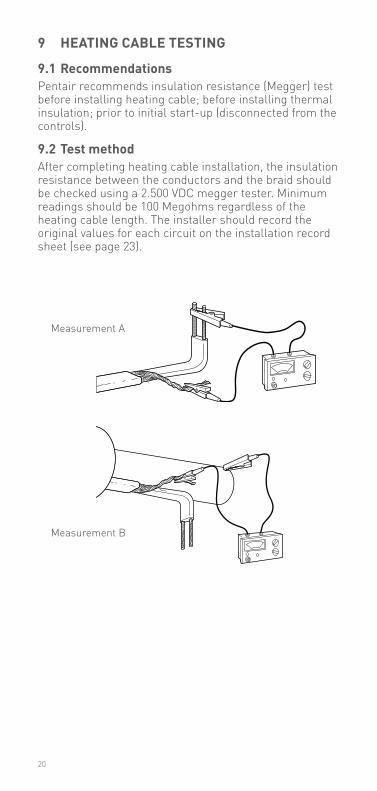
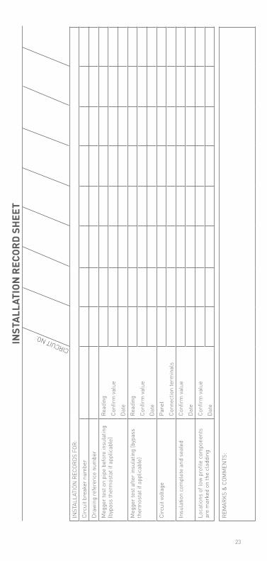
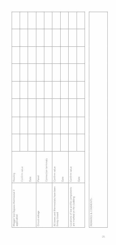
9.2 Test methodAfter completing heating cable installation, the insulation resistance between the conductors and the braid should be checked using a 2.500 VDC megger tester. Minimum readings should be 100 Megohms regardless of the heating cable length. The installer should record the original values for each circuit on the installation record sheet (see page 23).
Measurement A
Measurement B
20
10 OPeraTiOn, mainTenanCe and PiPe rePairS
10.1 heating cable operation Temperature exposure must not exceed that
specified in Pentair product literature. exceeding those limitations will shorten the service life and may permanently damage the heating cable.
Pipe insulation must be complete and dry to maintain the correct temperature.
10.2 inspection and maintenancede-energise all power circuits before installation or servicing and maintenance. Visual inspection: Exposed heating cable and pipe
insulation should be checked periodically to make sure that no physical damage has occured.
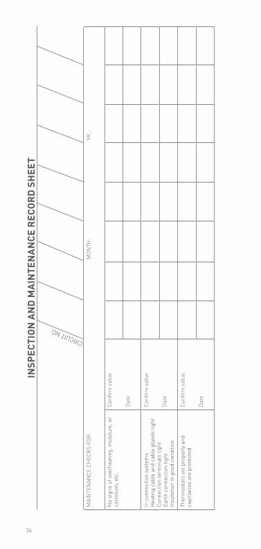
Function testing of electrical protection and temperature control systems should be carried out before the winter months each year (see section 10.2). Temperature maintenance systems should be tested at least twice a year.
The Periodic Inspection Record on the following pages should be filled out during maintenance of each circuit in your system.
10.3 Piping systems repair and maintenance Isolate heating cable circuit. Protect the heating cable from mechanical or
thermal damage during pipe repair work. Check heating cable installation after pipe repairs
and restore thermal insulation following the recommendations in Section 7. Check correct functioning of electrical protection systems.
21
11 heaTing CaBle damage
heating cable damage do not repair damaged heating cable.
Remove entire damaged section and splice in a new length using the appropriate Raychem splice kits.
replace damaged heating cable at once. Damage allowing moisture and contamination to enter the heating cable may result in arcing earth faults and potential fire hazards.
Heating cable exposed to fire or flame may cause further fire damage if powered. Remove from service at once and replace before re-use.
22
inST
alla
TiOn
reC
Ord
Shee
T
CIRCUIT NO.
INST
ALLA
TION
REC
ORDS
FOR
:Ci
rcui
t bre
aker
num
ber
Draw
ing
refe
renc
e nu
mbe
rM
egge
r tes
t on
pipe
bef
ore
insu
latin
g (b
ypas
s th
erm
osta
t if a
pplic
able
)Re
adin
gCo
nfirm
valu
eDa
teM
egge
r tes
t afte
r ins
ulat
ing
(byp
ass
ther
mos
tat i
f app
licab
le)
Read
ing
Conf
irm va
lue
Date
Circ
uit v
olta
gePa
nel
Conn
ectio
n te
rmin
als
Insu
latio
n co
mpl
ete
and
seal
edCo
nfirm
valu
eDa
teLo
catio
ns o
f low
pro
file
com
pone
nts
are
mar
ked
on th
e cl
addi
ngCo
nfirm
valu
eDa
te
REM
ARKS
& C
OMM
ENTS
:
23
inSP
eCTi
On a
nd
mai
nTe
nan
Ce r
eCOr
d Sh
eeT
CIRCUIT NO.
MAI
NTE
NAN
CE C
HEC
KS F
OR:
MON
TH:
yR.:
No
sign
s of
ove
rhea
ting,
moi
stur
e, o
r co
rros
ion,
etc
.Co
nfirm
valu
e
Date
In c
onne
ctio
n sy
stem
s H
eatin
g ca
ble
and
cabl
e gl
ands
tigh
t Co
nnec
tion
term
inal
s tig
htEa
rth
conn
ectio
n tig
htIn
sula
tion
in g
ood
cond
ition
Conf
irm va
lue
Date
Ther
mos
tats
set
pro
perly
and
ca
pilla
ries
are
prot
ecte
dCo
nfirm
valu
e
Date
24
Meg
ger t
est (
bypa
ss th
erm
osta
t if
appl
icab
le)
Read
ing
Conf
irm va
lue
Date
Circ
uit v
olta
gePa
nel
Conn
ectio
n te
rmin
als
All b
oxes
and
ther
mos
tats
hav
e be
en
firm
ly c
lose
dCo
nfirm
valu
e
Date
Loca
tions
of l
ow p
rofil
e co
mpo
nent
s ar
e m
arke
d on
the
clad
ding
Conf
irm va
lue
Date
REM
ARKS
& C
OMM
ENTS
:
25
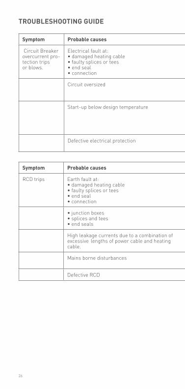
Symptom Probable causes Corrective action
RCD trips Earth fault at:• damaged heating cable• faulty splices or tees• end seal• connection
Investigate and remedy (see note 1):
• junction boxes• splices and tees• end seals
Dry out and reseal or remake immediately. Perform insulation resistance test. (100 MΩ minimum)
High leakage currents due to a combination of excessive lengths of power cable and heating cable.
Redesign
Mains borne disturbances Redesign distribution, guidance is available from Pentair.
Defective RCD Replace
Symptom Probable causes Corrective action
Circuit Breaker overcurrent pro-tection trips or blows.
Electrical fault at:• damaged heating cable• faulty splices or tees• end seal• connection
Investigate and remedy (see note 1):
Circuit oversized Resize or redesign within Technical Handbook Guidelines. (If larger protection is required, ensure supply cables are compatible).
Start-up below design temperature design for lower start-up temperatures.reheat pipe from alternative heat source to within exposure temperatures given in Product Data.energize part of circuit followed by remainder (e.g. in sequence).
Defective electrical protection Replace
TrOUBleShOOTing gUide
26
Symptom Probable causes Corrective action
RCD trips Earth fault at:• damaged heating cable• faulty splices or tees• end seal• connection
Investigate and remedy (see note 1):
• junction boxes• splices and tees• end seals
Dry out and reseal or remake immediately. Perform insulation resistance test. (100 MΩ minimum)
High leakage currents due to a combination of excessive lengths of power cable and heating cable.
Redesign
Mains borne disturbances Redesign distribution, guidance is available from Pentair.
Defective RCD Replace
Symptom Probable causes Corrective action
Circuit Breaker overcurrent pro-tection trips or blows.
Electrical fault at:• damaged heating cable• faulty splices or tees• end seal• connection
Investigate and remedy (see note 1):
Circuit oversized Resize or redesign within Technical Handbook Guidelines. (If larger protection is required, ensure supply cables are compatible).
Start-up below design temperature design for lower start-up temperatures.reheat pipe from alternative heat source to within exposure temperatures given in Product Data.energize part of circuit followed by remainder (e.g. in sequence).
Defective electrical protection Replace
TrOUBleShOOTing gUide
27
note:Locate faults by the following steps:1 Visually inspect the power connections, splices and end
seals for correct installation.2 Look for signs of damage at: a) Valves, pumps, flanges and supports. b) Areas where repairs or maintenance work has been
carried out.3 Look for crushed or damaged insulation and cladding
along the pipe.
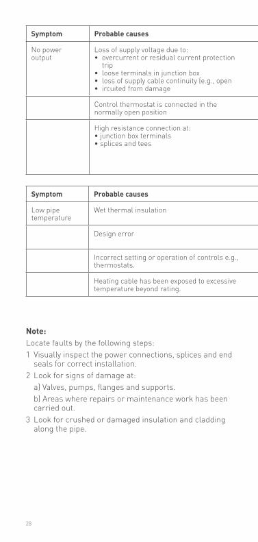
Symptom Probable causes Corrective action
Low pipe temperature
Wet thermal insulation Remove and replace with dry insulation of correct specification and ensure complete weatherproofing
Design error • check with competent authority for design conditions• modify to meet Pentair recommendations
Incorrect setting or operation of controls e.g., thermostats.
Repair or reset to correct level of operation
Heating cable has been exposed to excessive temperature beyond rating.
Replace
Symptom Probable causes Corrective action
No power output
Loss of supply voltage due to:• overcurrent or residual current protection
trip• loose terminals in junction box • loss of supply cable continuity (e.g., open • ircuited from damage
Restore supply voltage• following A and B (page 20) • re-tighten terminals NB: If excessive heating has occured due to high resistance, replace terminals or crimps• locate damage and repair
Control thermostat is connected in the normally open position
Reconnect to normally closed position
High resistance connection at:• junction box terminals• splices and tees
Locate and remedy by:• re-tighten• repair NB: If excessive heating has occured due to high resistance, replace terminals or crimps
28
Symptom Probable causes Corrective action
Low pipe temperature
Wet thermal insulation Remove and replace with dry insulation of correct specification and ensure complete weatherproofing
Design error • check with competent authority for design conditions• modify to meet Pentair recommendations
Incorrect setting or operation of controls e.g., thermostats.
Repair or reset to correct level of operation
Heating cable has been exposed to excessive temperature beyond rating.
Replace
Symptom Probable causes Corrective action
No power output
Loss of supply voltage due to:• overcurrent or residual current protection
trip• loose terminals in junction box • loss of supply cable continuity (e.g., open • ircuited from damage
Restore supply voltage• following A and B (page 20) • re-tighten terminals NB: If excessive heating has occured due to high resistance, replace terminals or crimps• locate damage and repair
Control thermostat is connected in the normally open position
Reconnect to normally closed position
High resistance connection at:• junction box terminals• splices and tees
Locate and remedy by:• re-tighten• repair NB: If excessive heating has occured due to high resistance, replace terminals or crimps
4 If after 1, 2 and 3 above the fault has not been located, then either:a) Consult Pentair for futher assistance.b) Where local practices and conditions allow (e.g., non
hazardous areas) isolate one section of heating cable from another by cutting in half and testing (e.g., Insulation Resistance) both halves until general area of damage is found. Remove insulation and expose fault.
29

30

31
WWW.PENTAIRTHERMAL.COM
Pentair is owned by Pentair or its global affiliates. All other trademarks are the property of their respective owners. Pentair reserves the right to change specifications without prior notice.
© 2017 Pentair.
BELgIë / BELgIquETel. +32 16 21 35 02Fax +32 16 21 36 [email protected]
BuLgARIATel./fax +359 56 86 68 86fax +359 56 86 68 [email protected]
ČeSká rePUBlikaTel. +420 241 009 215Fax +420 241 009 [email protected]
DANMARkTel. +45 70 11 04 00Fax +45 70 11 04 [email protected]
DEuTsCHLANDTel. 0800 1818205Fax 0800 [email protected]
EsPAñATel. 34 902 125 307Fax 34 91 640 29 [email protected]
FRANCETél. 0800 906045Fax 0800 [email protected]
HRvATskATel. +385 1 605 01 88Fax +385 1 605 01 88 [email protected]
ITALIATel. +39 02 577 61 51Fax +39 02 577 61 55 [email protected]
LIETuvA/LATvIjA/EEsTITel. +370 5 2136633Fax +370 5 [email protected]
MAgyARORszágTel. +36 1 253 7617Fax +36 1 253 [email protected]
NEDERLANDTel. 0800 0224978Fax 0800 [email protected]
NORgETel. +47 66 81 79 90Fax +47 66 80 83 [email protected]
ÖsTERREICHTel. 0800 297410Fax 0800 [email protected]
POLskATel. +48 22 331 29 50Fax +48 22 331 29 51 [email protected]
REPuBLIC OF kAzAkHsTANTel. +7 495 926 18 85Fax +7 495 926 18 86 [email protected]
РОССИЯТел. +7 495 926 18 85Факс +7 495 926 18 [email protected]
sERBIA AND MONTENEgROTel. +381 230 401 770Fax +381 230 401 [email protected]
sCHWEIz / suIssETel. 0800 551308Fax 0800 [email protected]
suOMIPuh. 0800 11 67 [email protected]
svERIgETel. 46 31 335 58 00Fax 46 31 335 58 [email protected]
TüRkIyETel. +90 530 977 64 67Fax +32 16 21 36 [email protected]
uNITED kINgDOMTel. 0800 969013Fax 0800 [email protected]
Raychem-IM-CDE1547-HeatTracingCOM-EN-1706PCN 1244-009261
Thermal managemenT