commercial / industrial steam & hot water boilers 15 psi...
TRANSCRIPT

www.RayesBoiler.com Firebox Series P a g e | 1 Copyright 2009
Commercial / Industrial Steam & Hot Water Boilers
15 PSI Steam 30 PSI Water Capacities From: 20 to 100 BHP 1000 to 4500 MBTU/HR.
Installation Operation Manual
For more information and a free analysis contact us at 773.275.0000 | www.RayesBoiler.com
Rayes Boiler | 8252 N. Christiana, | Skokie, Illinois 60076
www.RayesBoiler.com Firebox Series P a g e | 2 Copyright 2009
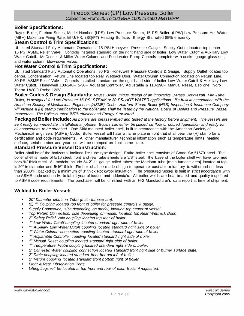
Firebox Series: (LP) Low Pressure Boiler Capacities From: 20 To 100 BHP 1000 to 4500 MBTU/HR
Boiler Specifications: Rayes Boiler, Firebox Series, Model Number (LPS), Low Pressure Steam, 15 PSI Boiler, (LPW) Low Pressure Hot Water
(MBH) Maximum Firing Rate, BTU/HR, (SQ/FT) Heating Surface. Energy Star rated 85% efficiency.
Steam Control & Trim Specifications: UL listed Standard Fully Automatic Operations: 15 PSI Honeywell Pressure Gauge. Supply Outlet located top center, 15 PSI ASME Relief Valve. Controls installed standard on the right hand side of boiler, Low Water Cutoff & Auxiliary Low Water Cutoff. McDonnell & Miller Water Column and Feed water Pump Controls complete with cocks, gauge glass set,
and water column blow-down valves.
Hot Water Control & Trim Specifications: UL listed Standard Fully Automatic Operations: 30 PSI Honeywell Pressure Controls & Gauge. Supply Outlet located top
center, Condensation Return Line located top Rear Wetback Door, Water Column Connection located on Return Line. 30 PSI ASME Relief Valve. Controls installed standard on the right hand side of boiler Low Water Cutoff & Auxiliary Low Water Cutoff. Honeywell 100-240F 5-30F Aquastat Controller, Adjustable & 110-290F Manual Reset, also one Hydro
Therm LWCO Probe 120V.
Boiler Codes & Design Standards: Rayes Boiler unique design of an innovative 3-Pass Down-Draft Fire-Tube
Boiler, is designed for Low Pressure 15 PSI STEAM or 30 PSI HOT WATER applications. It’s built in accordance with the
American Society of Mechanical Engineers {ASME} Code. Hartford Steam Boiler {HSB} Inspection & Insurance Company will include a {H} stamp certification to the boiler and shall be l isted by the National Board of Boilers and Pressure Vessel
Inspectors. The Boiler is rated 85% efficient and Energy Star listed.
Packaged Boiler Include: All boilers are preassembled and tested at the factory before shipment. The vessels are
sent ready for immediate installation at jobsite. Boilers can either be placed on floor or poured foundation and ready for all connections to be attached. One Skid mounted boiler shell, built in accordance with the American Society of Mechanical Engineers {ASME} Code. Boiler vessel will have a name plate in front that shall bear the {H} stamp for all
certification and code requirements. All other manufacturer technical information such as temperature limits, heating surface, serial number and year built will be stamped on front name plate.
Standard Pressure Vessel Construction: Boiler shall be of the horizontal inclined fire tube type design. Entire boiler shell consists of Grade SA 51670 steel. The boiler shell is made of 5/16 steel, front and rear tube sheets are 3/8” steel. The base of the boiler shell will have two mud bars ¾” thick steel. All models include 84 2” 11-gauge rolled tubes; the Morrison tube {main furnace area} located at top
is 20” in diameter and 5/16” thick. Firebox shall be made of high temperature cast able refractory to withstand not less than 2000°F, backed by a minimum of 3" thick Rockwool insulation. The pressured vessel is built in strict accordance with the ASME code section IV, to latest year of issues and addenda’s. All boi ler welds are heat-treated and quality inspected
to ASME code requirements. The purchaser will be furnished with an H-2 Manufacturer’s data report at time of shipment.
Welded to Boiler Vessel:
20” Diameter Morrison Tube {main furnace are}. (2) 1” Coupling located top front of boiler for pressure controls & gauge.
Supply Connection, size depending on model, location top center of vessel. Top Return Connection, size depending on model, location top Rear Wetback Door. 2” Safety Relief Vale coupling located top rear of boiler.
1” Low Water Cutoff coupling located standard right side of boiler. 1” Auxiliary Low Water Cutoff coupling located standard right side of boiler. 1” Water Column connection coupling located standard right side of boiler.
1” Adjustable Controller coupling located standard right side of boiler. 1” Manual Reset coupling located standard right side of boiler. 1” Temperature Probe coupling located standard right side of boiler.
2” Domestic Water coupling connection located standard front right side of burner surface plate. 2” Drain coupling located standard front bottom left of boiler. 2” Return coupling located standard front bottom right of boiler.
Front & Rear Observation Ports. Lifting Lugs will be located at top front and rear of each boiler if requested.

www.RayesBoiler.com Firebox Series P a g e | 3 Copyright 2009
Standard Removable from Boiler: One bolted on 20” diameter burner nozzle plate with opening, size depending on burner model. Total of 84 straight 2”
O.D., 11 gauges, rolled {ASME} Fire-Tubes, SA 178 Grade A steel. Hinged Front and Rear Doors are standard on all models. Doors are to be sealed with heat resistant gasket and fastened using lugs and brass nuts. Front and Rear flame observation ports will also be included. The bottom of the Rear Hinged Door will be the location for t he exhaust
connection, typically 12” on all models. Units are factory insulated with minimum 2” thick mineral wool material. The boiler jacket shall be of not less than 18 gauge steel with galvanized finish. The entire boiler base frame and other components shall be factory painted before shipment, using a heat resistant enamel coating.
Warranty: All equipment is to be guaranteed against defects in materials and/or workmanship for a period of 12 months from date of shipment.
Firebox Series: Steam & Hot Water System
All Steel 3-Pass Down-Draft Fire-Tube Packaged Boiler
15 PSI Steam 30 PSI Hot Water Capacities From: 20 to 100 BHP 1000 to 4500 MBTU/HR.
High Efficiency All Steel 3-Pass Down-Draft Firetube Boiler Design Flexibil ity - Gas, Oil, Heavy Oil, and Combination Gas/Oil
ASME Code Constructed & Stamped for 15 PSI Steam/30 PSI Water Registered with the National Board of Boiler Inspectors Energy Star Rated 85% Efficient
Competitively Priced, Easily Maintained, Designed for Efficiency Large Furnace Volume for Ultimate Combustion Efficiency Low Heat Release Factory Insulated - Mineral Wool Material
Small Footprint Design for Easy Accessibility Hinged Front & Rear Doors for Easy Access to Tubes Optional Universal Hinged Wetback Door
2” Front Side Cleanout Openings 2” Domestic Water Connection Standard Fully Automatic Operation Controls U.L. Listed, Forced Draft Burners
U.L. Listed Controls & Trim Factory Test Fired & ASME Approved Flame Observation Ports Front & Rear
FIREBOX BOILER FEATURES:
Competitively priced with a designed footprint to fit through 32” doorways. The Firebox Series eliminates difficulty site assembly and building alterations, often giving the customer an option of keeping the existing boiler in place and avoiding removal expenses. The choice of any standard burner is designed to be installed at the top front of the boiler for enhanced heat temperature transfers to the main connection. The concave bottom helps with the collection of mud and sludge along the sides of the interior of the boiler, for an easier
washout when needed. The front and rear hinged doors swing open to allow easy access while cleaning tubes. The Energy Star rated 85% efficiency Firebox line of boilers is manufactured for the use in Low Pressure 15 PSI
Steam and 30 PSI Hot Water applications, providing for efficient operation and low cost maintenance. It’s built and stamped in accordance with the requirements of the ASME Code, and listed by the National Boa rd of
Boilers and Pressure Vessel Inspectors.

www.RayesBoiler.com Firebox Series P a g e | 4 Copyright 2009
Table of Contents
Section 1 – Safety Warnings and Precautions 1. Introduction 2. Safety Warnings and Precautions
Section 2 – Installation 1. Boiler Dimensions and Operating Requirements 2. General Information 3. Items Supplied with the Boiler 4. Locating and Installing the Boiler 5. Positioning the Boiler 6. Installing Boiler Trim 7. Installing Water Piping 8. Low Water Cut Off 9. Water Chemistry 10. Oxygen Contamination 11. Filling the Boiler with Water 12. Installing Gas Piping 13. Components Requiring Ventilation to the Outdoors 14. Installing Condensate Drain Pipe 15. Venting General 16. Exhaust Venting 17. Electrical Connections
Section 3 – Operation 1. After Installation and Prior to Start Up (General) 2. Gas Supply Piping 3. Electrical 4. Boiler or Appliance 5. Burner 6. Test Instruments 7. Variable Speed Drive Blower Motor 8. Test of Ignition Safety System
Section 4: Boiler Care & Maintance 1. Daily Procedures 2. Weekly Procedures 3. Monthly Procures 4. Annual Procedures 5. Care of Idle Boilers 6. Care & Service of boilers & Tubes 7. Boiler Tube Replacement 8. Sight Glass Removal

www.RayesBoiler.com Firebox Series P a g e | 5 Copyright 2009
Section 1 INTRODUCTION
North Shore Boiler Repair, Inc. has served the greater metropolitan Chicago land area with the highest level of professionalism. We listen and anticipate to our customer’s needs, only to deliver the service
promised. With North Shore Welding & Boiler Repair, Inc., our customers get the most reliable and effective solutions.
Over the years, we have developed an efficient 3 Pass steel fire tube boiler design with a force downdraft system. This patented design minimizes the amount of BTU’s, hence, minimizes the cost of gas. Furthermore, this astonishing innovation encompasses a reduced gas line from a standard 4” to a 1 ½.” Constructed according to ASME section IV standards, the Rayes Boiler is shielded with heavy welded steel to ensure continuous airtight conditions necessary for efficient combustion. The Rayes Boiler is factory test-fired and hydro tested at 60 psi to Hartford Steam Boiler standards. It is registered with and approved by Energy Star for 85% efficiency. The Rayes Boiler is reliable, easily maintained
and has saved property owners over half the cost of their gas bill. Our Installation Crews are headed by the most knowledgeable people in the industry, with solid years of on-
site experience. During the Installation Process, we educate your maintenance staff with the proper use, care and maintenance of your boiler. We are committed to provide you with the highest quality product and
workmanship at the most reasonable price.
A. This manual is provided as a guide to the correct operation and maintenance of your Rayes Firebox Boiler, and should be permanently available to the staff responsible for the operation of
the boiler.
B. These instructions must not be considered as a complete code of practice, nor should they
replace existing codes or standards, which may be applicable.
C. The requirements and instructions contained in this section generally relate to the standard Rayes Firebox Boiler. When installing a packaged unit, this entire section should be read to
ensure that the installation work is carried out correctly.
D. Prior to shipment the following tests are performed to assure the customer the highest standards of manufacturing.
I. Material inspections. II. Manufacturing process inspections. III. ASME welding inspections. IV. ASME hydrostatic test inspection. V. Electrical components inspection. VI. Operating test. VII. Final engineering inspection
VIII. Crating inspection.
E. All units are crated for transport. Under no circumstances should weight be allowed to bear on the jacket, control panel, or any part of your Rayes Boiler.
F. A competent rigger experienced in handling heavy equipment should handle rigging your boiler
into position.

www.RayesBoiler.com Firebox Series P a g e | 6 Copyright 2009
G. The customer should examine the boiler for any damage. It is the responsibility of the installer
to ensure all parts supplied with the boiler are fitted in a correct and safe manner.
H. Competent personnel in accordance with all applicable local codes should carry out the installation of the Rayes Firebox Boiler. All state and jurisdictional codes beyond the scope of the applicable ASME Boiler and Pressure Vessel Codes, for its corresponding classification should be followed in all cases. Jurisdictional authorities must be consulted prior to installation.
SAFETY WARNINGS AND PRECAUTIONS
WARNING Operating the boiler beyond its design limits can damage the boiler and can be dangerous. Do
not operate the boiler outside its limits. Do not try to upgrade the boiler performance by unapproved modifications. Unapproved modifications can cause injury and damage. Contact
your Rayes dealer before modifying the boiler. WARNING
A defective boiler can injure you or others. Do not operate a boiler, which is defective or has missing parts. Make sure that all maintenance procedures are completed before using the
boiler. Do not attempt repairs or any other maintenance work you do not understand. Obtain a Service Manual from Rayes Boiler or call a Rayes Representative.
WARNING
If the information in this manual is not followed exactly, a fire or explosion may result
causing property damage, personal injury or loss of life. Do not store or use gasoline or other flammable vapors and liquids in the vicinity of this or any
other appliances.
WHAT TO DO IF YOU SMELL GAS • Do not try to light any appliance.
• Do not touch any electrical switch; do not use any phone in your building. • Immediately call your gas supplier from a neighbor’s phone.
Follow the gas supplier’s instructions. • If you cannot reach your gas supplier, call the fire department. A qualified installer, service agency or the gas supplier must perform installation and service.
WARNING
A qualified installer, service agency, or gas supplier must perform installation and service. Contact your Rayes Boiler representative for guidance.
CAUTION
The discharge from the safety relief valve shall be so arranged that there will be no danger of scalding personnel or damage to equipment. When the safety relief valve discharge is piped
away from the boiler to the point of discharge, there shall be provisions made for properly draining the piping.

www.RayesBoiler.com Firebox Series P a g e | 7 Copyright 2009
For Your Safety
The following WARNINGS, CAUTIONS, and NOTES appear in various sections of this manual. They are repeated on these safety summary pages as an example and for emphasis. WARNINGS must be observed to prevent serious injury or death to personnel. CAUTIONS must be observed to prevent damage or destruction of equipment or loss of operating effectiveness. NOTES must be observed for essential and effective operating procedures, conditions, and as a statement to be highlighted. It is the responsibility and duty of all personnel involved in the operating and maintenance of this equipment to fully understand the WARNINGS, CAUTIONS, and NOTES by which hazards are to be eliminated or reduced. Personnel must become familiar with all aspects of safety and equipment prior to operation or maintenance of the equipment.
WARNING No shutoff of any kind shall be placed between the safety relief valve and the boiler or in the discharge pipe between such valve and the atmosphere. Doing so can cause an accidental explosion from overpressure. A. CAUTION The discharge from the safety relief valve shall be so arranged that there will be no danger of scalding personnel or damage to equipment. When the safety relief valve discharge is piped away from the boiler to the point of discharge, there shall be provisions made for properly draining the piping. B. WARNING No shutoff of any kind shall be placed between the safety relief valve and the boiler or in the discharge pipe between such valve and the atmosphere. Doing so can cause an accidental explosion from overpressure. C. CAUTION Some soap used for leak testing is corrosive to certain types of metals. Rinse all piping thoroughly with clean water after leak check has been completed. D. WARNING Do not use matches, candles, flame or other sources of ignition to check for gas leaks. E. WARNING Do not use the boiler as support for ducted air piping. Ducted piping must be supported independently of the boiler. F. WARNING Cements for plastic pipe are flammable liquids and should be kept away from all sources of ignition. Proper ventilation should be maintained to reduce the hazard and to minimize breathing of cement vapors. Avoid contact of cement with skin and eyes. G. WARNING Never install a barometric damper on flue systems designed with positive pressure. H. CAUTION Assure all electrical connections are powered down prior to attempting replacement or service of electrical components or connections of the boiler.

www.RayesBoiler.com Firebox Series P a g e | 8 Copyright 2009
I. WARNING If you do not follow these instructions exactly, a fire or explosion may result causing property damage, personal injury, or loss of life. J. WARNING Do not attempt to start the boiler for any testing before filling and purging the boiler. A dry fire will seriously damage the boiler and may result in property damage or personnel injury and is not covered by warranty. K. CAUTION Never leave an opened manual air vent unattended. In the event an opened vent is left unattended, water damage could occur. L. WARNING Before commissioning the boiler, verify with authorized personnel that the gas lines have been purged. M. WARNING Never attempt to operate a boiler that has failed to pass all the safety checks described below. N. WARNING After checking controls by manual adjustment, make sure they are always reset to their proper settings. O. CAUTION Do not attempt to alter any password protected preset values unless you are factory trained personnel. P. WARNING A qualified and knowledgeable individual, such as a Rayes Boiler representative, qualified installer, service agency, or gas supplier, must perform Installation and service. Q. WARNING Proper lockout / tagout procedures must be employed when servicing this unit. R. WARNING Label all wires prior to disconnection when servicing controls. Wiring errors can cause improper and dangerous operation. S. WARNING Follow proper lockout / tagout procedures for the electrical, gas, and water connections. Use caution when lifting heavy parts. T. WARNING Heat Exchanger is heavy and may cause injury if improperly handled. Only knowledgeable and experienced personnel should perform removal of the heat exchanger.
CAUTION: The air switch has been factory set and should not be adjusted in the field.

www.RayesBoiler.com Firebox Series P a g e | 9 Copyright 2009
1. BOILER DIMENSIONS AND OPERATING REQUIREMEN Section 2
Specification Sheet: (All DIMENTIONS ARE IN INCHES)
MODEL NO. 20 40 60 80 100
BOILER HORSEPOWER BHP 20 40 60 80 100 GAS INPUT (BTU. per hour) 1,000 BTU/CF MBH MAX 1,000,000, 2,000,000 3,000,000 3,500,000 4,500,000
OIL INPUT, #2 (Gals. per hour) 140,000 BTU GPH 9 12 18 24 30
GROSS OUTPUT (BTU. per hour) 1,000 BTU/CF MBH MIN 850,000 1,700.000 2,550,000 2,975,000 3,400,000 TOTAL BOILER HEATING SURFACE SQ. FT. 98 186 257 348 441
RADIANT HEATING SURFACE SQ. FT. 13.5 21 29 39 50
FURNACE VOLUME CU. FT. 5.6 8.7 12.17 16.35 20.71 FURNACE HEAT RELEASE MBH / CU. FT. 206 205 205 205 205
A BOILER LENGTH WITHOUT ANY DOORS BOILER SHELL IN 37 48 67 90 114 A
B OVERALL LENGTH WITH WETBACK DOOR W/ STD. BURNER IN 80 99 118 141 165 B C REAR WETBACK DOOR LENGTH IN 12 16 16 16 16 C
D REAR WETBACK DOOR HEIGHT IN 53 55 55 55 55 D
E REAR WETBACK DOOR WIDTH IN 26 29 29 29 29 E
F FRONT DOOR LENGTH IN 12 16 16 16 16 F G FRONT DOOR HEIGHT IN 18 21 21 21 21 G
H FRONT DOOR WIDTH IN 26 29 29 29 29 H
I HEIGHT WITHOUT TRIM IN 60 67 67 67 67 I J HEIGHT WITH TRIM IN 73 80 80 80 80 J
K WIDTH WITHOUT TRIM IN 26 31 31 31 33 K
L WIDTH WITH STACK & TRIM APPROX. IN 49 56 56 56 56 L M STACK DIAMETER O.D. IN 8 10 10 10 10 M
N STACK HEIGHT IN 22 22 22 22 22 N
O FRONT MORRISON TUBE DEPTH IN 4 4 4 4 4 O P SUPPLY 15-STM. & 30-WTR. IN 3 4 6 6 6 P
Q SUPPLY LOCATION IN 18.5 24 34 45 57 Q
R RETURN SIZE 30-WTR. IN 2 3 3 3 3 R S DRAIN SIZE IN 2 2 2 2 2 S
T SAFETY RELIEF VALVE IN 2 2 2 2 2 T
U DOMESTIC WATER CONNECTION IN 2 2 2 2 2 U
V BOILER FIRETUBE DIAMETER ROLLED IN 2 2 2 2 2 V APPROX SHIPPING WEIGHT W/ REFRACTORY LBS. 3,827 4,320 4,870 5,537 6,231
WATER CAPACITY (HOT / WATER) GALS. 496 577 668 778 892
WATER CAPACITY STEAM GALS. 449 532 626 739 856

www.RayesBoiler.com Firebox Series P a g e | 10 Copyright 2009
Cad Drawings: 2003 U.S Patent No. 6564756 (A) 15 PSI Honeywell Pressure Gauge
(B) Honeywell Limit Control Manual Reset 2-15 PSI (C) Honeywell Pressure Snap Control 15 (D) Honeywell Limit Control Manual Reset 2-15 PSI
(E) McDonnell & Miller Low H20 Cutoff Man Reset 120V (F) McDonnell & Miller Cutoff Switch 61 (G) Conbraco ½ Gauge Glass Kit (H) Beckett Burner
(I) McDonnell & Miller Electric Water Feeder 120V (J) 1” Ball Valve (K) 1” Union (L) 1” Cross Fitting
(M) 2” Return (N) 2” Drain (O) Stack
(P) Flame Observation Port (Q) 2” 11 Gauge Fire Tubes (R) 2” Domestic Water Connection (S) Supply
(T) 2” 90 Fitting (U) 2” T Fitting (V) 2” Union
(W) 2” ASME Relief Valve (X) 2” Flex Hose (Y) 2” Condensation Return Line (Z) Blow Down
Rayes Boiler Firebox LPS 15 PSI Steam Boiler

www.RayesBoiler.com Firebox Series P a g e | 11 Copyright 2009
Cad Drawings: 2003 U.S Patent No. 6564756 (A) 15 PSI Honeywell Pressure Gauge (B) McDonnell & Miller Low H20 Cutoff Man Reset 120V
(C) Honeywell Aquastat 100/240 (D) Honeywell Aquastat 110/290 (E) McDonnell & Miller Low H20 Cutoff Man Reset 120V (F) McDonnell & Miller Cutoff Switch 61
(G) Conbraco ½ Gauge Glass Kit (H) Beckett Burner (I) Water Feeder Fitting
(J) 1” Ball Valve (K) 1” Air Vent (M) 2” Return (N) 2” Drain
(O) Stack (P) Flame Observation Port (Q) 2” 11 Gauge Fire Tubes (R) 2” Domestic Water Connection
(S) Supply (T) 2” 90 Fitting (V) 2” Union
(W) 2” ASME Relief Valve (X) 2” Flex Hose (Y) 2” Condensation Return Line (Z) Blow Down
Rayes Boiler Firebox LPW 30 PSI Hot Water Boiler

www.RayesBoiler.com Firebox Series P a g e | 12 Copyright 2009
2. GENERAL INFORMATION
A. This instruction manual must be posted and maintained in a legible condition. B. The Rayes Firebox Steam Boiler is an automatic, fuel-fired, ultra high-efficiency boiler. The
boiler can either be of the sealed combustion/direct vent type or utilize conventional combustion air intake and flue methods.
C. The boiler is capable of sidewall venting when the appropriate venting materials are used and when permitted by local code requirements.
D. Each boiler is constructed to ASME Section IV and is certified to Hartford. All Rayes Boilers are hydrostatically tested, test fired and shipped as a complete packaged unit.
E. Fuel, water and electrical connections are similar to other boilers of this type.
F. All installations must be in accordance with American National Standard “National Fuel Gas Code”, latest edition, and with the requirement of local utilities or other authorities having
jurisdiction. Such applicable requirements take precedence over general instructions herein. G. Since an external electrical source is utilized, the boiler, when installed, must be electrically
ground in accordance with the National Electric Code, ANSI-NFPA 70, and latest edition. H. This Firebox boiler is to be installed as part of a hydronic heating system. Rayes cannot be held
responsible for the selection, engineering, installation, or sizing of any additional equipment or components of the hydronic heating system. A qualified engineer must be consulted for the selection of the equipment and components of the heating system. Various system conditions
can result in incorrect heat distribution to users of the heating system.
3. EACH FIREBOX BOILER IS SUPPLIED WITH THE FOLLOWING
A. Operating and high temperature probes B. Low water probe in pressure vessel
C. ASME pressure relief valve D. Instruction manual
E. Separate wiring diagram
F. Temperature and pressure (T&P) gauge G. 2” drain valve
H. 1 can touch up paint

www.RayesBoiler.com Firebox Series P a g e | 13 Copyright 2009
4. LOCATING AND INSTALLING THE RAYES BOILER
A. NOTE: The boiler shall be installed such that the ignition system components are protected from water (dripping, spraying, rain, etc.) during boiler operation and service. Note. The boiler must be installed on a non-combustible surface.
B. NOTE: “Factory-Trained Personnel” refers to someone who has attended a Rayes Boiler service school specifically for to the Firebox Series model.
C. SAFETY COMPONENTS: The end user of the Firebox Boiler must maintain all labels on the boiler in clean, legible condition. All connections and safety devices, both mechanical and electrical, must be kept clean, kept with ease of access for inspection, use and maintenance.
D. WARNING: A qualified installer, service agency, or gas supplier must perform Installation and
service. Contact you Rayes Boiler representative for guidance. E. COMPLIANCE WITH CODES:
F. The Rayes Boiler Firebox is manufactured and stamped in accordance with ASME Boiler and Pressure Vessel Code, Section IV for a maximum allowable working pressure and temperature of 15psi and 240F respectively.
Installation of the boiler must conform to all the requirements of all national, state and local codes established by the authorities having jurisdiction or, in the absence of such requirements, in the U.S. to the National Fuel Gas Code, ANSI Z223.1/NFPA54, latest edition, and the specific
instructions in this manual. Authorities having jurisdiction should be consulted before installations are made.
Where required by local codes, the installation must conform to American Society of Mechanical Engineers
Safety Code for Controls and Safety Devices for Automatically Fired Boilers (ASME CSD-1).
5. POSITIONING THE BOILER
A. The boiler should be located so that the air supply and exhaust piping between the boiler and outside wall/roof are within the maximum lengths for horizontal or vertical venting if sealed
combustion will be used. See Figure 1 for minimum clearances between the boiler and any
combustible surfaces. This boiler must be installed on a non-combustible level base. A concrete base is preferable.
B. 1” side clearance is acceptable between boilers. The standard Maxon and optional low emissions burner configuration requires a short radius elbow on the air inlet connection to be
able to be installed with 1” side clearance. This short radius elbow is available from the factory. The Beckett burner configuration permits 1” side clearance as standard.
C. CAUTION: This boiler is certified for indoor installation only. D. NEMA 3R Configuration is available as an option from the factory, but an existing boiler cannot
be retrofitted for outdoor installation. E. Ensure that the Firebox boiler is installed on a level surface and oriented in the vertical position. F. Protect gas ignition system components from water (dripping, spraying, rain etc.) during boiler
operation and service (circulator replacement, condensate trap service, control replacement etc.)
G. Provide combustion and ventilation air in accordance with applicable provisions of local building codes or: USA – National Fuel Gas Code, NFPA 54/ANSI Z223.1, Section 5.3, Air for Combustion and Ventilation.

www.RayesBoiler.com Firebox Series P a g e | 14 Copyright 2009
6. INSTALLING BOILER TRIM
A. Safety Valve Each Firebox boiler is supplied with a safety relief valve sized in accordance with ASME requirements. The safety relief valve shall be connected to the coupling located in the top of the boiler. The safety relief valve must always be installed in the vertical position. The discharge pipe diameter shall not be less than the full area of the valve outlet. The discharge pipe shall be as short and straight as possible and so arranged as to avoid undue stress on the valve. The discharge piping shall be supported by means other than the safety valve itself, and must be piped to avoid danger of scalding personnel. Safety relief valve size is determined by trim pressure and is supplied in the trim kit along with
appropriate bushing; inlet and outlet sizes are as follows:
CAUTION The discharge from the safety relief valve shall be so arranged that there will be no danger of scalding personnel or damage to equipment. When the safety relief valve discharge is piped away from the boiler to the point of discharge, there shall be provisions made for properly draining the piping. WARNING
No shutoff of any kind shall be placed between the safety relief valve and the boiler or in the discharge pipe between such valve and the atmosphere. Doing so can cause an accidental
explosion from overpressure.
B. Each boiler is supplied with a pressure-temperature gauge to be installed in the outlet piping section of the boiler.
www.RayesBoiler.com Firebox Series P a g e | 15 Copyright 2009
7. INSTALLING WATER PIPING
A. All water supplies contain some solids, dissolved gases or dissolved minerals. These may
promote corrosion, deposition and/or fouling of equipment. To prevent these contaminants from impacting on boiler performance, valve operation and general pipe longevity, each location must be analyzed and treated accordingly.
B. The Rayes Firebox boiler does not require a primary/secondary flow piping system. Although primary/secondary is an acceptable configuration; the boiler does not have a minimum return water temperature requirement and the heat exchanger will not be harmed by low flow or zero flow conditions.
C. All water supplies contain some solids, dissolved gases or dissolved minerals. These may promote corrosion, deposition and/or fouling of equipment. To prevent these contaminants
from impacting on boiler performance, valve operation and general pipe longevity, each location must be analyzed and treated accordingly.
D. The Rayes Firebox boiler does not require a primary/secondary flow piping system. Although primary/secondary is an acceptable configuration, the boiler does not have a minimum return water temperature requirement and the heat exchanger will not be harmed by low flow or zero flow conditions.
E. Isolation valves are recommended on both water connections for ease of service.
F. Piping must be installed such that the boiler is not supporting any additional piping. G. The water connection on the top of the boiler is the outlet connection. The water connection
on the rear of the boiler is the inlet connection. H. Install manual purging valves in all loops and zones. Install a pressure-reducing (automatic fill)
valve in the cold water fill line to the boiler system. Check that the proposed operation of zone valves, zone circulator(s) and diverting valves will not isolate air separator(s) and/ or expansion
tank(s) from the boiler. Clearance from hot water pipes to combustibles must be at least 6”. I. The boiler, when used in conjunction with a refrigeration system, must be installed so the
chilled medium is piped in parallel with the boiler with appropriate valves to prevent the chilled medium from entering the boiler. If the boilers are connected to heating coils, located in air
handling units where they may be exposed to refrigerated air circulation, such boiler piping
systems shall be equipped with flow control valves or other automatic means to prevent gravity circulation of the boiler water during the cooling cycle.
J. The mechanical equipment in the hydronic heating system should include: I. An automatic pressure activated water make up valve with back flow preventer set to maintain:
II. Air removal equipment, including an air separator and automatic breather valves, along with a functioning expansion tank designed to system specifications.
III. Filtration to remove particulates. IV. Bypass chemical feeder for corrosion inhibitor maintenance.
V. Corrosion coupon holder to assess corrosion inhibitor performance. a. Required NPSH for re-circulating pumps b. A positive system pressure at the highest point of at least 5-10 PSIG c. Make up water valve should be designed to add water to the system at the outlet of the boiler
and should not be fed directly into the boiler.

www.RayesBoiler.com Firebox Series P a g e | 16 Copyright 2009
K. The boiler is provided with a drain valve connection and a drain valve. L. Before installing a Firebox boiler into a hydronic loop, be sure that the system piping and any
other components of the system are clean and free of debris and any foreign matter. The hydronic system is completely flushed prior to installing the boiler itself. Install a strainer upstream of each boiler to ensure that no foreign matter will have the opportunity to get inside the heat exchanger. Heat exchanger failure due to foreign matter or debris damage is not covered under the warranty.
WARNING
The hydronic system should never be flushed while the boiler is attached to the system since
the debris could accumulate in the boiler and block water from passing through the heat exchanger
WARNING
The piping system attached to this unit will be chemically cleaned, the boiler must be disconnected from the system and a bypass installed so that the chemical cleaning solution does not circulate through the boiler.
8. Low Water Cut Off
To prevent burner operation whenever a low water condition occurs, a single pole double
throw float operated level switch is furnished in the water column. Cut-off is wired in series to the burner combustion safeguard control.

www.RayesBoiler.com Firebox Series P a g e | 17 Copyright 2009
9. WATER CHEMISTRY
A. System water chemistry requirements: I. Oxygen: Less than 250 ppb (operating condition) II. Total Iron/Copper: Less than 5 ppm III. Corrosion Inhibitor: Less capable of maintaining iron corrosion rates <2 mpy 1. Due to changing environmental restrictions a non-heavy metal ALL ORGANIC inhibitor is
recommended which is designed for multi metal systems including ferrous metals and yellow metals such as copper and brass.
IV. Chloride: Less than 10 ppm
B. Refer to your water conditioning or chemical treatment supplier for analysis and recommendations for proper system conditions. Follow a program with appropriate monitoring
and maintenance of system water conditions as provided by your water conditioning or chemical treatment supplier.
C. The boiler warranty does not cover heat exchanger failure due to inappropriate water quality. D. System design professionals should consider the variety of conditions the heating system will
experience. E. Firebox boilers should be operated in a closed-loop system using water or water/glycol (not
requiring a make-up water supply). A large amount of improperly treated make-up water can
cause premature failure of the heat exchanger resulting from scale build up. Heat exchanger failure due to scale is not covered under the warranty. Scale build up will reduce the efficiency
and useful life of the boiler.

www.RayesBoiler.com Firebox Series P a g e | 18 Copyright 2009
10. OXYGEN CONTAMINATION
A. Care needs to be taken to eliminate oxygen from the water system, as excess oxygen in the system will reduce the life of any boiler. The boiler warranty does not cover heat exchanger replacement due to oxygen contamination of boiler water.
B. There are several ways to prevent boiler water oxygen contamination: I. Minimize system leaks to minimize make up water requirement II. Do not use open tanks or fittings III. Do not use oxygen permeable materials anywhere in the water system IV. Repair leaks in the system quickly V. Eliminate fittings wherever possible
VI. Use air elimination devices in system piping. C. An air separator and air eliminator (air vent) is required to be installed. There are no built in
boiler air eliminating features. To prevent scale corrosion in boiler and associated piping , make up water must be kept to a minimum. This is best achieved by ensuring immediate repair of all leaks and that system pressure is maintained.
D. If a sealed diaphragm-type expansion tank is used, install an air eliminator in the hot water piping at the air separator.
I. If an air cushion type expansion tank is used, pipe tank directly into boiler supply. II. On multi-zoned systems (or a system with both space and domestic water heating), air
elimination must be provided either in the common piping or on every loop. III. When the boiler is installed at a higher level than baseboard radiation (if used), air elimination
must be provided directly above the unit.
11. FILLING THE BOILER WITH WATER
A. To be sure that the boiler is not air-bound, open the pressure-relief valve located at the rear of the boiler. Leave the relief valve open until a steady flow of water is observed. Close the valve
and finish filling the system. Water level should be 5” above main furnace tube.
12. INSTALLING GAS PIPING
A. See the table for required natural gas pipe size, based on overall length of pipe from the meter
plus equivalent length of all fittings. Approximate sizing may be based on 1,020 BTU for 1 cubic foot of natural gas.
B. The Firebox boiler is factory test fired and combustion is adjusted per the boiler data plate and
test fire sheet.
C. The gas train components are UL-795 certified to operate at specific gas pressure requirements. The specific requirements for each boiler are called out on the boiler nameplate, located on the back of the boiler. Parameters depend on what fuel(s) the boiler is designed to operate with.
D. Piping must be installed such that no piping stresses are transmitted to the boiler. The boiler shall not be used as a pipe anchor.

www.RayesBoiler.com Firebox Series P a g e | 19 Copyright 2009
E. The boiler and all gas piping connections should be pressure-tested and must be checked for
leaks before being placed into service. Test with compressed air or inert gas if possible.
F. The boiler must be disconnected at the boiler manual shutoff valve (located at the end of the supplied gas train) from the gas supply piping system during any pressure testing of the system at pressures in excess of 1/2 psig (14 inch W.C.).
G. Gas Piping should be installed in accordance with National Fuel Gas Code, ANSI Z223.11991 or
latest addenda and any other local codes, which may apply.
H. The pipe and the fittings used should be new and free of dirt or other deposits.
I. Piping must be of the proper size to insure adequate gas supply. A drip leg and union
connection should be installed upstream of the gas safety shut off valves.
J. Connect gas supply line to the open end of the tee on which the drip leg is installed.
k. When making gas-piping joints, use a sealing compound resistant to liquefied petroleum gases. Do not use Teflon tape on gas line threads.
L. After gas piping is completed and before wiring installation is started, carefully check all piping connections, (factory and field), for gas leaks. Use a soap and water solution.
CAUTION: Some soap used for leak testing is corrosive to certain types of metals. Rinse all piping thoroughly with clean water after leak check has been completed.
M. The boiler must be disconnected at the boiler shut off valve from the gas supply piping system
during any pressure testing of the system.
N. NOTE: The vent line connection on the gas pressure regulator must be piped to outdoor air by the installer in accordance with the National Fuel Gas Code, ANSI Z223-1-1991 or latest
addenda. In Canada gas installations must by in accordance with the current CAN/CGA B149.1
and 2 and/or local codes.
WARNING: Do not use matches, candles, flame or other sources of ignition to check for gas leaks.
13. COMPONENTS REQUIRING VENTILATION TO THE OUTDOORS A. Although there are custom fuel train requirements available that does not include components
requiring ventilation to the outdoors, most Firebox fuel trains will require a vent line on the high gas pressure switch and the gas pressure regulator.
I. High gas pressure switch II. Gas pressure regulator

www.RayesBoiler.com Firebox Series P a g e | 20 Copyright 2009
14. Installing Condensate Drain Piping
I. A condensate collecting tank and condensate pump will be required if a floor drain is not available to collect condensate (collecting tank and pump are not supplied with the boiler).
II. PH neutralization kits are available from the factory, if desired. III. All piping must be galvanized or stainless steel and should be free of leaks. Copper, carbon
steel/iron pipe, PVC or CPVC are not acceptable. IV. Connect 1” condensate drain(s) (at the rear of the boiler on the lower right), to the 1” inlet at
the base of the drain tank. The bottom of the drain kit must be a minimum of 5.5” lower than the bottom of the boiler when connected in a manifold; the manifold must be 5.5” below the condensate outlet and must remain flooded.
V. Connect the 1.5” drain outlet to an appropriate waste line following applicable codes. The 1.5” drain connection on the drain tank must be the highest point prior to going to the drain. Failure
to keep drain piping lower than this point will result in overflow of the drain tank. Slope the drain pipe away at a minimum pitch of 1” for every 12 feet.
VI. Attach a ¼” water supply to the compression fitting on the float. The water line must be connected to an uninterruptible supply. Rayes recommends connecting it before the “fast fill” valve to the boiler supply but after the back flow preventer to avoid contamination of a potable water supply. Maximum allowable water pressure to the compression fitting is 100 PSI.
A. WARNING: The minimum return water temperature to the boiler is 160oF when firing on oil.
Failure to maintain this will void the warranty. B. The Firebox dual fuel boiler is suitable for firing light distillate fuel oil, commonly known as # 2
fuel oil. DO NOT USE GASOLINE, CRANKCASE OIL OR ANY OIL CONTAINING GASOLINE. If in doubt, contact your Rayes representative prior to operation.
C. Fuel pipes should be of approved materials and of a diameter suitable for the quantity of oil being delivered to the burner and the static head available. A stop valve and fire valve assembly
should be supplied by the client/contractor. In additional a check valve should be fitted into the return pipe.
D. The maximum pressure allowed at the fuel oil pump inlet is limited to 3 PSIG by the National Fire Protection Association (NFPA). If the fuel supply can exceed this maximum, a regulator
must be installed. The minimum pressure at the pump inlet should never exceed 10” of
vacuum. E. The oil pump on the Firebox boiler is a SUNTEC model AJ4CC. No settings are required for the
pump, which is set to 174 PSI by the manufacturer. This pressure must be checked and adjusted (if required) after the burner has been ignited. There is a pressure gauge provided with the oil
pump assembly on the boiler so pressure can be monitored.

www.RayesBoiler.com Firebox Series P a g e | 21 Copyright 2009
15. VENTING General
A. General Venting Requirements: I. The Rayes Boiler can operate to the combined intake and flue pressure drops
Without derate: The boiler can be installed with either direct venting or a conventional venting arrangement. With either venting configuration, the difference in pressure readings at the boiler exhaust connection and air intake connection cannot exceed the maximum value stated in the table. This means that the combined pressure drop through the air intake venting (if installed) and exhaust venting cannot exceed the maximum value stated in the table. If it does, the boiler will have to be de-rated. Also, the pressure at the boiler exhaust connection must not exceed a maximum negative value as stated in the table. This pressure must remain relatively
constant throughout the operation of the boiler. Drastic draft changes during operation may result in generation of carbon monoxide or soot. To decrease termination noise, increase the
venting size at the termination points. This will slow the air velocity causing a reduction in noise. Do not terminate the venting in an enclosed area. Care must be taken when selecting the orientation of the terminations.
B. Consult your venting pipe supplier for assistance with sizing of vent materials and other potentially required accessories.
C. Combustion Air Supply from the Boiler Room I. Adequate combustion air and ventilation must be supplied to the boiler room in accordance
with local codes and NFPA54/ANSI Z233.1, Section 5.3, Air for combustion and ventilation. II. The boiler room must meet the NFPA criteria for a non-confined space
III. It is important to provide free access of air to the boiler. To burn fuel properly, it requires 0.4 square inch opening of fresh air for every 1,000 BTU input of fuel (2.58 cm2 for every 252Kcal).
IV. Consistent proper ventilation of the boiler room is essential for good combustion. Install two fresh air openings, one at a low level, 24” (610 mm) from the floor, and one at a higher level in
the boiler room wall. This will provide a flow of air to exhaust the hot air from the boiler room. V. The following openings are recommended for each installation size:
For multiple boiler installations, multiply the number of boilers by required free area per boiler.
VI. Per ASME Section VI Para. 6.04, an unobstructed air ventilation opening should be sized on the basis of one square inch free area per 2000 BTU/HR maximum fuel input of the combined
burners located in the boiler room. This is subject to state and local regulations. The installation of exhaust fans in a boiler room is not recommended.
VII. An exhaust fan or similar equipment can create down draft in the stack or restrict the burner’s air supply which will result in poor combustion. It is essential that only fresh air is allowed to
enter the combustion air system. Foreign substances, such as combustible volatiles and line in the combustion system can create hazardous conditions. If foreign substances can enter the air
stream, the boiler combustion air inlet must be piped to an outside location. Failure to do so will void the warranty.
VIII. Particulate matter or chemicals (example: perchlorethylene, halogenated compounds) in the combustion air supply to the boiler will cause damage or failure to the burner and is not
covered under warranty. High-risk situations for particulate matter to be in the air include construction and maintenance activities.

www.RayesBoiler.com Firebox Series P a g e | 22 Copyright 2009
D. Air Piped From Outside Boiler Room I. The combustion air supply can be piped directly to the air inlet of the boiler. II. A rubber air intake coupling is supplied with boilers specified for installation with ducted air
supply. It must be used to connect the intake piping to the boiler air inlet. III. WARNING
Do not use the boiler/burner as support for ducted air piping. Ducted piping must be supported independently of the boiler.
IV. The air intake must be piped out of the building if the boiler room contains contaminated air. V. Air Intake pipes and fittings shall be Schedule 40 PVC pipe or galvanized steel. All Schedule 40
PVC pipe, fittings, primer and cement must conform to American National Standard Institute and the American Society for Testing and Materials (ANSI/ASTM standards.)
VI. Intake PVC piping must be assembled using cement. This will ensure that the intake is air tight and will not allow contaminates from the boiler room into the boiler. The cement shall be free
flowing and contain no lumps, un-dissolved particles or any foreign matter that adversely affects the joint strength or chemical resistance of the cement. The cement shall not show gelation, stratification, or separation that cannot be removed by stirring.
VII. WARNING Cements for plastic pipe are flammable liquids and should be kept away from all sources of ignition. Proper ventilation should be maintained to reduce the hazard and to minimize breathing of cement vapors. Avoid contact of cement with skin and eyes.
VIII. The following procedure for cementing joints (per ASTM D2855) should be adhered to: 1. Measure and cut PVC pipe to desired length.
2. Chamfer end of pipe, removing any ridges or rough edges. If end is not chamfered, the edge of the pipe may remove cement from the fitting socket and result in a leaking joint.
3. Clean and dry surfaces to be joined. 4. Test fit joint and mark depth of fitting on pipe outside.
5. Uniformly apply a liberal coat of primer to inside socket surface of fitting and male end of pipe to depth of fitting socket.
6. Promptly apply solvent cement to end of pipe and inside socket surface of fitting. Cement should be applied lightly—but uniformly—to inside of socket. Take care to keep excess cement
out of socket. Apply second coat to pipe end.
7. NOTE Time is critical at this stage. Do not allow primer to dry before applying the cement.
8. Immediately after applying last coat of cement to pipe, while inside socket surface and end of pipe are wet with cement, insert end of pipe into socket, turn pipe 1/4 turn to distribute
cement evenly, continue to insert pipe until it bottoms out. A. NOTE
Assembly should be completed within 20 seconds after last application of cement. Do not use a hammer to insert pipe.
9. After assembly, wipe excess cement from pipe at end of fitting socket. A properly made joint will show a bead around its entire perimeter. Any gaps may indicate a defective assembly due to insufficient cement.
10. Handle joints carefully until completely set.
11. Galvanized steel joints should be sealed with adhesive aluminum tape

www.RayesBoiler.com Firebox Series P a g e | 23 Copyright 2009
16. Exhaust Venting:
A. The Firebox boiler is equipped with a vent connection at the lower rear of the boiler. B. The boiler requires a category IV stack. The stack material must be either AL29-4C or 316L
stainless steel and comply with UL-1738 or UL-103. Venting installation must comply with National Fuel Gas Code, ANSI Z233.1, Part 10 or applicable provisions of local building codes.
C. The exhaust line must be sloped down toward the drain with a pitch of at least 1/4" per foot. Failure to do so can result in a condensate pocket, which can result in an inoperative boiler. There must be no low spots in the exhaust pipe, as this can also result in a condensate pocket. A high spot is acceptable, provided the pitch from the high spot is maintained back to the boiler to the outside point of the exhaust. Always avoid rigid connections between piping and
structural members of the building. D. The exhaust vent installer should be familiar with these Federal Codes as well as local codes and
regulations. E. Follow vent manufacturer’s instructions for installation of exhaust venting. F. The condensate connection on the boiler should be piped into the stack drain piping. The pipe
from the boiler directed to the drain should be installed at a slope of ¼” per foot. G. Ensure that the condensate drain piping will not be exposed to temperatures where
water/condensate will freeze in the lines. H. Sizing Exhaust Vent
I. Exhaust vents must be sized to ensure less than a 0.35” pressure drop between the air intake and flue exhaust venting. This is the equivalent of 35 feet and 4 elbows of boiler connection size
pipe (combining the distances between the intake and the exhaust pipes). I. Venting Terminations:
All vent pipes and fittings must be installed with appropriate air space clearances to combustibles. These air space clearances apply to indoor or outdoor vents —whether they are
open, enclosed, horizontal or vertical or pass through floors, walls, roofs, or framed spaces. The air space clearances should be observed to joists, studs, subfloors, plywood, drywall or plaster
enclosures, insulating sheathing, rafters, roofing, and any other material classed as combustible.
II. The required minimum air space clearances also apply to electrical wires and any kind of
building insulation. III. Adequate provision must be made to support the weight of the exhaust venting. It cannot be
supported by the boiler exhaust connection. IV. Listed termination parts must be used.
V. Select the air intake point of penetration where a minimum of 1/4" per foot upward pitch can be maintained.
VI. When penetrating a non-combustible wall, the hole through the wall must be large enough to maintain the pitch of the vent and provide sealing. Use adhesive material to seal around the
vent on both sides of the wall. When penetrating a combustible wall, a wall thimble must be used. See Figure 16 for installation instructions. Minimum wall thickness through which vent system may be installed is 3.25". Maximum wall thickness through which vent system may be installed is 20 inches.

www.RayesBoiler.com Firebox Series P a g e | 24 Copyright 2009
J. Wall Thimble Installation to the wall with nails or screws, and seal with adhesive material.
Install the inside flange to the inside wall, secure with nails or screws, and seal with adhesive material. Pass the vent pipe through the thimble from the outside and join to the rest of the vent system. Seal the pipe to the thimble flange with adhesive material. Install two pipe retaining clamps around the intake as well as vent pipes on both ends of the wall thimble (on the inside and outside of the wall) through which intake and vent pipes are passed. They will prevent the intake and vent pipes from being pushed or pulled.
K. Horizontal Vent Termination L. The vent termination is joined to the vent pipe outside the wall. Use the same joining
procedures for vent pipe and fittings. The termination of the vent system must be at least 12" above the finished grade, or at least 12" above normal snow accumulation level (for applicable
geographical areas). Refer back to previous page, Figure 4. The termination of the vent system shall not be located in traffic areas such as walk ways, adjacent buildings, operable windows
and building openings unless the venting system is at least 7ft. above finished grade, (National Fuel Gas Code, ANSI Z223.1). The vent terminations must be at least 4 feet (1.22m) horizontally from electric meters, gas meters, regulators, and relief equipment.
II. When installing inlet and exhaust terminations on the same wall, the exhaust outlet must be installed 4ft. minimum above and downwind from air supply inlet to prevent exhaust recirculation. Under certain wind conditions, some building materials may be affected by flue products expelled in close proximity to unprotected surfaces. Sealing or shielding of the
exposed surfaces with a corrosion resistant material (such as an aluminum sheet) may be required to prevent staining or deterioration.
III. Do not locate the vent termination too close to shrubbery as flue products may stunt their growth or kill them.
IV. The minimum vent height should extend at least 3 feet above the roof, or at least 2 feet above the highest part of any structure within 10 feet of the vent.
V. If the exhaust vent terminates within 10 ft. horizon-tally of the air inlet, the exhaust vent must be at least 3 ft. above the inlet. Dimensions listed above and those illustrated are minimum,
and may or may not be sufficient for conditions at a specific job site. VI. To prevent the possible re-circulation of flue gases, the vent designer must take into
consideration such things as prevailing winds, eddy zones, building configurations, etc. FHS
cannot be responsible for the effects such adverse conditions may have on the operation of the boilers. It is important to locate the exhaust duct in such a way that it does not become blocked
due to snow, ice, and other natural or man-made obstructions. M. Common Exhaust Venting of Multiple Boilers
I. Consult your venting supplier for guidance in designing common vented installations. It is imperative to design such systems to prevent backflow of exhaust gases through idle boilers.
II. Firebox boilers cannot be common vented with other equipment. III. The pressure drop across the common headers (combined air intake and exhaust) cannot
exceed the pressure drop requirements specified in the table from section 17a in this manual. IV WARNING: Never install a barometric damper on flue systems designed with positive pressure. V. Removing an Existing Boiler 1. When an existing boiler is removed from a common venting system, the common venting
system is likely to be too large for proper venting of the appliances remaining connected to it.

www.RayesBoiler.com Firebox Series P a g e | 25 Copyright 2009
2. At the time of removal of an existing boiler, while the other appliances remaining connected to
the common venting system are not in operation, the following steps should be followed with each appliance remaining connected to the common venting system placed in operation:
A. Seal any unused openings in the common venting system. B. Visually inspect the venting system for proper size and horizontal pitch and determine that
there is no blockage or restriction, leakage, corrosion or other deficiency, which could cause an unsafe condition.
C. Insofar as is practical, close all building doors and windows and all doors between the space in which the appliances remaining connected to the common venting system are located and other spaces of the building. Turn on clothes dryers and any appliances not connected to the common venting system. Turn on any exhaust fans, such as range hoods and bathroom
exhausts, so they will operate at maximum speed. Do not operate a summer exhaust fan. Close fireplace dampers.
D. Place the appliance being inspected in operation. Follow the lighting instructions. Adjust the
thermostat so that the appliance will operate continuously.
E. Test for spillage at the draft hood relief opening after 5 minutes of main burner operation. Use the flame of a match or candle or smoke from a cigarette, cigar or pipe.
F. After it has been determined that each appliance remaining connected to the common venting system properly vents when tested as outlined above, return doors, windows, exhaust fans,
fireplace dampers and any other gas-burning appliance to their previous conditions of use. VI. Any improper operation of the common venting system should be corrected so the installation
confirms with the National Fuel Gas Code, ANSI Z223.1. When resizing any portion of the common venting system, the common vent system should be resized to approach the minimum
size as determined using the appropriate tables.
17. ELECTRICAL CONNECTIONS Install the burner and all wiring in accordance with the National Electric Code ANSI/NFPA 70 (Canada
CSA C22.1) and all applicable codes and requirements. Wire the burner in compliance with all instructions and diagrams provided by the appliance manufacturer. Verify operation of all controls in
accordance with the appliance manufacturer’s guidelines. Sequence of Operation
The primary control enters the INITIATE sequence when the control is first powered on or power returns after an interruption. The initiate sequence is a ten second delay during which the control verifies line voltage stability. Standby – The control enters STANDBY until the limits, operating limit control, burner switch, and all microcomputer-monitored circuits are in the correct state.
Load Demand Operating limit control contacts close on drop in temperature (or pressure) and initiate the
start sequence.

www.RayesBoiler.com Firebox Series P a g e | 26 Copyright 2009
Pre-purge
The control will signal the PREPURGE sequence when the airflow interlock and all switches are in the correct state. The Pre-purge sequence is the amount of time the blower motor runs prior to the ignition start sequence. Timing for the Pre-purge sequence is determined by a card mounted inside the control module (typically 30 seconds). For the RM7897A control, Pre-purge is conducted with the air damper in the low fire position. For the RM7840 control the air damper opens to the high fi re position for the timed pre-purge period and returns to the low fi re position before releasing the control for ignition. Trial for Ignition (TFI) – After the Pre-purge sequence has timed out, the ignition and main gas valves will be energized. Because the burner has direct spark ignition for the main flame, the flame must be established and detected by the control within 4 seconds or lockout will occur. Flame Stabilization – The burner will operate in
low fire for 10 seconds before initiating high fire. Run – With a flame established and the control continuing to detect a flame, the burner will operate in the RUN mode until the load
demand is satisfied or a limit opens. The burner starts at Low and goes to High after the flame stabilization period. Flame is extinguished when the load is satisfied or a limit opens, and the burner is sent to post purge. For High/Low control wiring, if a high / low control has been wired between terminals RC1 and RC2 the burner starts at Low and is released to go to High after the flame stabilization period. It can repeatedly cycle between low and high as necessary to meet load demand until the load is satisfied or a limit opens, and the burner is sent to post purge.
For modulating control wiring, the burner starts at Low and is released to modulate after the flame stabilization period. It can modulate between low and high as necessary to meet load
demand until the load is satisfied or a limit opens, and the burner is sent to post purge. Load Satisfied
The fuel valves are closed. After a 15 second post purge, the burner switches to idle until the next call for operation. This operation sequence is typical and for reference only. The primary control could vary, depending on the customer specification and code requirements. For the specific operating sequence that applies to your installation, consult the appliance manufacturer’s directions, wiring instructions, and control manufacturer’s literature supplied with your burner. Prepare the Burner for Start-up This burner must be installed and prepared for startup by a qualified service technician who is trained and experienced in commercial gas burner system installation and operation. Carefully follow the wiring diagrams, control instruction sheets, flame safeguard sequence of operation, test procedures and all appliance manufacturer’s directions that pertain to this instal lation. If any of these items are not clear or are unavailable, call Beckett at 1-800-645-2876 for assistance. Delayed Ignition, Explosion and Fire Hazards This is a direct spark ignition burner and by code requirements must have a primary control with a 4 -second flame establishment period. Exceeding 4 seconds could result in delayed ignition, explosions and fire. Always verify the primary control has a 4-second flame establishment period by carefully following the control manufacturers’ configuration instructions. Example: Honeywell RM Series requires clipping and removing the JR1 resistor.
www.RayesBoiler.com Firebox Series P a g e | 27 Copyright 2009
Section 3
Start-up Checklist
Verify the following before attempting to start the burner. 1. General
Carefully read and become familiar with the manual, flame safeguard control instructions, sequence of operation, pertinent wiring diagrams, gas system layout, insurance requirements,
other controls and valve literature pertinent to the installation. Follow the appliance manufacturer’s start-up procedures (when available). Inspect the combustion air supply and exhaust venting and verify that they are free of obstructions and installed and sized in accordance with all applicable codes. Notify appropriate personnel to schedule start-up (gas utility, owner, operators, subcontractors, etc.).
2. Gas Supply Piping
Insure that the gas piping is properly sized and has been inspected by the gas utility; leak tested at all joints, and purged. To protect the gas train and controls, insure that a drip leg or dirt pocket has been properly installed. Insure that the fuel gas being supplied is compatible with
the burner specification and is available at the correct regulated pressure. (See burner name plate and specification sheets). Insure that the vent lines for the diaphragm valves have been
run to the outside and properly terminated. Use RWB recommended maximum pipe lengths for good light-off
3. Electrical
Insure that all wiring has been completed and complies with the National Electric Code NFPA 70 and local requirements and verify that the electrical supply to the burner matches the voltage specification on the label.
4. Boiler or Appliance
Insure that the flue passages and combustion area have been thoroughly cleaned and are in good condition. Set the breech damper to the required position for system operation. Fill the
appliance with water (boilers). Check all safety and operating controls for correct application, installation, wiring, and operation. Insure that the maximum capacity of the appliance is
compatible with the specified burner input fi ring rate.
5. Burner Insure that the gas burner model and capacity meet the requirements for the installation.
Insure that the gas train meets operating specifications, all safety codes and insurance
requirements. Insure that the burner air damper is positioned for initial start-up preliminary settings. Insure that the burner is securely mounted in the appliance with the pressure fi ring
plate and all gaskets in place for pressurized chamber applications. For propane-fi ring burners, insure that the propane restrictor has been correctly selected for your burner model and
properly installed (see Propane Restrictor Installation instructions). Before operating insure that all protective cover plates, enclosures and guards are in place and securely fastened. When
available, refer to the appliance manufacturer’s instructions and install the burner accordingly.

www.RayesBoiler.com Firebox Series P a g e | 28 Copyright 2009
6. Test Instruments
The following calibrated test equipment is required to properly install the appliance. Whether these are included in one kit or are individual test components, they should be calibrated and in good working order. A combustion analyzer capable of measuring oxygen (or carbon dioxide), carbon monoxide, stack temperature, ambient temperature, and appliance efficiency. Electrical multi-meter capable of measuring voltage, ohms, amps, and DC micro-ammeter for measuring the flame signal. These could be included in one meter or separate meters, but should be calibrated and accurate. Calibrated manometers and gauges capable of measuring all pressure ranges in the gas supply and appliance draft. This could typically range from a few P.S.I to 0.01” W. C. Having several manometers or U tubes with the correct range can simplify the testing and set up procedures. This burner must be installed and prepared for startup by a qualified service
technician who is trained and experienced in commercial gas burner system installation and operation. Do not attempt to start the burner unless you are fully qualified. Do not continue
with this procedure until all items in the ‘Prepare the Burner for Start-up’ section have been verified. Carefully follow the wiring diagrams, control instruction sheets, flame safeguard sequence of operation, test procedures and all appliance manufacturer’s directions that pertain to this installation. If any of these items are not clear or are unavailable, call Beckett at 1-800-645-2876 for assistance.

www.RayesBoiler.com Firebox Series P a g e | 29 Copyright 2009
Burner Start Procedure
(Before proceeding, turn off and lock out electrical power and close the main leak test cock to shut off gas to the burner.) With the power and main gas supply to the burner turned off, make sure gas has not accumulated in the boiler or flues. Check the initial air settings for the input fi ring rate. Check the manufacturer’s settings either on the nameplate if adjustment is necessary and set the damper motor cam so that the indicator points to the values shown on the nameplate or listed in Table 3. With the main gas supply valve closed. Set the limit or controller to call for heat then apply power to start the burner. Reset the high and low gas pressure switches if necessary. In order to check the function of each component ( i.e.: flame safeguard sequence, airflow proving switch, ignition transformer, gas valves, safety lockout timing, etc.), with the gas supply closed off, monitor a complete burner run sequence. Note that the flame safeguard control will
lock out since the fuel supply has been closed off. If component operation sequence and function is correct, reset the flame safeguard and initiate a new cycle. Monitor the start-up cycle and manually open the main
leak test cock as soon as the flame safeguard powers the safety shutoff valves. If the boiler room is quiet you may be able to hear the valve open, if not you can generally place your hand on the valve and feel it open. After you have observed main flame for a brief time, trip any of the switches in the limit string to shut the burner down. Monitor the flame and safety shutoff valves to assure that shutdown is controlled by the valves and that they operate properly. With this test passed you may safely initiate automatic start-ups on subsequent cycles.
Initial Air Settings If your burner was built for a specific OEM (Original Equipment Manufacturer) application, the “MFR’s
Settings” label will indicate the application and the initial air settings made at Beckett. Please verify those settings using the following procedure. If your burner was not built for a specified application, the following
steps outline the procedure for initially setting the damper (these settings may be different from settings specific to a particular OEM).
Refer to Figure 10A and 10B for this procedure. Figure 10A - Damper Motor with Cover
Remove the cover screw (A) then the cover (B) and set aside .Push in on pin (G) to disengage the
motor from the damper shaft and cam stack.
Rotate the damper shaft by hand to place the adjustment cams in a position where their
adjustment scale can be easily seen.
Release pin (G) to secure the damper shaft and camstack to the motor. Using the wrench
(C) supplied with the damper motor, adjust the blue low fi re cam (D) to the initial
setting listed in Table 3.

www.RayesBoiler.com Firebox Series P a g e | 30 Copyright 2009
Using the same wrench, adjust the red high fire cam Figure 10B - Damper Motor with Cover Removed (H) To the initial settings listed in Table 3. To adjust the high fire transition, use a small straight edge screwdriver. For high/low fi ring burners, turn the white adjustment screw located in the orange transition cam (J) until the cam indicator is half way between the high and low settings on the scale. For modulating burners the orange transition cam is not used. After setting all the cams, make sure the damper shaft and cam
stack is set between its low fire setting and its high fi re setting. (If you don’t it may not move when it is powered.) Push in pin (G),
Move the damper by hand so that notch (E) is between the low fire setting and high fi re setting on scale (F), then release pin (G) to re- engage the motor. When the motor is powered it will go to its low fire setting. This initial setting should be adequate for starting the burner at low fire. Once the burner is in operation, the air setting will be adjusted for best performance as discussed later in this manual. Don’t forget to re-install the cover after all
the adjustments have been made.
NOTICE The damper plate is attached by screws to its shaft, and bears against a flat on the shaft for alignment. The shaft is secured to the damper motor by a sleeve coupling with two setscrews bearing against the damper shaft and two more against the motor shaft. The motor shaft has a flat matching the one on the damper shaft. The flats on the damper shaft and the motor shaft should be aligned so that the position indicator in the damper motor reads Legend (Figures 10A & 10B) accurately. The best way to align the flats is to tighten the setscrews that bear against the flats on the shafts A - Cover screw F - Damper motor scale first, and then tighten the ones that bears against the B – Cover G - Disengaging pin round surface of the shafts afterward. C – Wrench H - High fire cam (red)
D - Low fire cam (blue) J - Transition cam E - Cam notch (orange)
The test for proper alignment is to disengage the damper motor from its shaft using the disengaging pin (Item G in Figure 10B) and rotate the damper plate to its full closed position. The position indicator should point to 0° within.

www.RayesBoiler.com Firebox Series P a g e | 31 Copyright 2009
Section 4 Boiler Care & Maintenance
1. Daily Procedures
1. Blowdown primary low water cut-off while burner is firing. 2. Verify that the feedwater pump cycles normally and that burner shut off.
3. Observe the burner starting sequence and flame characteristics to verify normal behavior. 4. Conduct visual check of all pressure and temperature gauge readings. 5. Check safety valve, hand holes, and man way for signs of leakage.
2. Weekly Procedures 1. Check function of auxiliary low water cut-off while burner is firing. Verify proper response of
alarms. 2. Check flame safety control’s response to lack of flame with main gas OFF. Start burner with
pilot OFF, verify lock-out. 3. During and after flame failure test, observe ignition spark and pilot flame for abnormalities. 4. Record pilot and main flame signals if digital display module is available. 5. If boiler is equipped with modulating burner, verify that adequate differential exists between
operating and modulating controls to Prevent short cycling.
6. Verify that main fuel valves are closing within specified times. Check valve position indicators.
3. Monthly Procedures 1. Check air flow switches mechanically and electrically. Snap switches can stick in closed position
if shaft is dirty. Disconnect wire, start burner, verify that pilot does not light.
2. Check low fire start proving switch circuit with voltmeter. Terminal must not be powered until motor returns to low fire position. If wire is disconnected, verify that pilot does not light.
3. Check open damper proving switch circuit with voltmeter. Terminal must not be powered until motor reaches high fire position. If wire is disconnected, verify that motor remains at high fire position.
4. Test main gas valves for leakage. Close checking cock, connect hoses to open lead test valves, submerge hose ends in water, and watch for bubbling.
5. Test fuel pressure interlock switches. With burner in normal operation (preferably at high fire), raise low gas or oil pressure switch setpoint above available fuel pressure. Burner must shut off
when visual indicator trips. Test high gas pressure switch by reducing setpoint below existing manifold pressure. Again, burner must shut off when indicator trips.
6. After returning to normal setpoints, burner must no restart until switches have been manually rest.
7. Test oil atomizing medium interlock by interrupting flow of compressed air or steam to burner. Oil valves must close, with subsequent flame safeguard lock-out.
8. Manually lift safety valve set with test level while boiler is at normal operation pressure. 9. Check flame safety control’s response to lack of flame with main gas OFF. Start burner with
pilot OFF, verify lock-out.

www.RayesBoiler.com Firebox Series P a g e | 32 Copyright 2009
4. Annual Procedures
1. Since the low water cut-off wiring terminal strips tend to be at the highest operating
temperatures found in the boiler control circuit, check wire insulation for brittleness, cracking, or missing patches.
2. Clean all safety control related piping, including low water cut-off equalizers, pressure control manifolds, and air flow switch tubes.
3. Check boiler pressure gauge against calibrated master gauge or with dead weight tester. New gauges are built to 1% accuracy.
4. Jumper operation control and run boiler under manual control at reduced load to determine proper operation of limit.
5. Bypass both operating and high limit controls under manually controlled low load condition. Gradually bring boiler pressure up to safety valve set point. 15 psi valves must open at 15 psi.
Valves rated 15 psi to 69 psi are permitted 2 psi tolerance, and 70 psi to 300 psi valve vary 3%. 6. Remove gas line strainer basket and clean.
5. Care of Idle Boilers
1. Boilers used on a seasonal basis that will be idle for a long period of time (in excess of 30 days)
should be laid up either under a dry or wet method during periods of inactivity. 2. Boilers Laid up Dry In the event that the boiler could be subject to freezing temperatures or if
the boiler is to be idle for an excessive period of time, the following preparation should be made and carried out so that the boiler is not damaged over its period of inactivity:
3. Drain and clean the boiler thoroughly (both fire and water sides) and dry the boiler out. 4. Place lime or another water absorbing substance in open trays inside the boiler and clos e the
unit tight to exclude all moisture and air. 5. All allied equipment such as condensate tanks, pumps, etc., should be thoroughly drained.
6. Boilers Laid up Wet In order to protect the boiler during the short periods of idleness, the boiler is laid up wet in the following manner:
7. Fill the boiler to overflowing with hot water. The water should be approximately 120°F to help
drive out the free oxygen. Add enough caustic soda to the hot eater to maintain approximately 350 parts per million of alkalinity and also add enough sodium sulphide to produce a residue of
50 to 60 parts per million of this chemical. 8. Check all boiler connections for leaks and take a weekly water sample to make sure that the
alkalinity and sulphide are stable. When cleaning a boiler in preparation to laying up the boiler, the water side of the unit should be cleaned and then the unit fired to drive off gases. The fire
side should then be cleaned. An oil coating of fire side metal surfaces is benefic ial when the boiler is not used for extended periods of time. This will prevent oxidization of the metal. Fuel
oil lines should be drained and flushed of residual oil and refilled with distillate fuel. If oil boilers are to be laid up, care of oil tanks, lines, pumps and heaters is similarly required.
www.RayesBoiler.com Firebox Series P a g e | 33 Copyright 2009
6. Care & Service of Boiler Tubes
1. Hard water causes short tube life in scotch marine boilers. Chemical action from hard water
plus oxygen in the water will attack the boiler tubes. This action can be so drastic that tubes may be pitted through in a few months.
2. Water that is too soft (zero soft) causes pitting of tubes and boiler plates below the water line. Ideal feed water is 3 to 6 grains in hardness. Water that is too soft is usually apparent because it causes a bouncing water level in the gauge glass and usually causes foaming and priming, throwing water into the main steam piping.
3. When first installed, new boiler may develop leaks around the tube ends. While the boiler was tight and showed no leaks during final hydrostatic testing by the ASME inspector (third party),
leaks often develop after the boiler has been shipped some distance. If leaks do not take up and stop after the boiler has been operated for 24 hours, tubes that are leaking must be slight re-
rolled. 4. Re-rolling of the tubes to sop leaks, when the boiler is new or if it has been in service for some
time, is a very delicate procedure. There is danger of over-rolling. When the tubes are installed in a new boiler, they are rolled just enough to prevent leakage. Re-rolling must be done on the same basis. The boiler should be subjected to a small amount of water pressure when tubes are being re-rolled. The tube roller can then be used sparingly and just enough to stop the leaks. Even one turn of the tube roller may be too much. Over rolling makes the tubes so thin that
during expansion and contraction boiler pressure will bend the thin part of the tube inward. The tube will then leak constantly, making it necessary to replace the tube.
If tubes leak at rolled joints after boiler had been in service for some time, the cause of such leaks is usually
one of the following:
1. Firing the boiler when it is low water. 2. Lime and scale deposits around the tubes near the rolled joints. This insulates the joint from the
water and permits overheating of the tube ends, causing leakage. 3. Feeding water to the boiler at any point near tube sheets may cause the boiler leak. Ins truction
sheets show the proper feed water inlet. Scotch marine boilers have water inlets halfway up
the side of the boiler shell. 4. Boiler can be chilled causing leaks by blowing the boiler completely down when it is too hot.
Boiler pressure should not exceed 15 psi for complete blow down. 5. Boiler can be chilled causing leaks by filling with cold water too soon after blow down. After
complete blow down and before filling with water, the boiler should be allowed to cool for two hours if there is no internal firebrick and three hours if there is an internal firebrick-lined
combustion chamber.

www.RayesBoiler.com Firebox Series P a g e | 34 Copyright 2009
7. Boiler Tube Replacement
1. Prior to tube replacement, it is necessary to have these tools available: 2. Tube driving mandrel and sledge hammer, or cutting torch 3. Chisel 4. Tube roller, properly sized for boiler tube diameter and thickness 5. Flaring tool 6. Beading tool 7. Socket wrench 8. Oil
In addition to these basic tubes, tube replacement is simplified with the following equipment: 1. Air compressor or air source
2. Small air hammer 3. Impact wrench or tube rolling motor
Boiler Tube Removal, Method A
A. In most cases the boiler tube will be covered with scale, therefore it is extremely difficult to pull
the tube out of the tube sheet. Equipment is available that can easily remove scale encrusted tubes through their respective tube holes; however these tools are very costly.
B. Using a chisel, carefully remove the bead from one end of the tube to be replaced. IMPORTANT: Extreme care must be exercised when using the chisel so the tube sheet and the
tube hole are not damaged. C. A special driving mandrel must be placed into the tube end from which the bead has to be
removed. The mandrel must fit inside the end of the tube and its shoulder must be able to pass through the tube hole in the tube sheet. Preferably the mandrel should be attached to the end
of a steel rod about 2' or 3’ in length. After inserting the mandrel with its rod into the tube, a sledge hammer can be used to drive the tube out of the tube sheet. After the tube extends
about 2’ from the opposite tube sheet, it can generally be manipulated to crush the adhering
scale as it is physically removed. As mentioned above, tube removal by this method is very difficult.
Boiler Tube Removal, Method B
A. IMPORTANT: This method of tube removal with a cutting torch can be used ONLY if the tube to
be removed can be withdrawn from a handhold opening. It is not possible to remove a tube severed with a cutting torch from a tube hole.
B. In this method the tube is severed with a cutting torch and is removed through a hand hole opening.

www.RayesBoiler.com Firebox Series P a g e | 35 Copyright 2009
8. Sight Glass Removal & Installation
1. Boiler and pump should be switched off. Boiler should be cool and the water level should be below the lower water gauge fixture. Close the upper and lower water gauge valves.
2. Loosen both sight glass packing nuts (top and bottom) with a wrench. Slide glass carefully upward into the upper fixture. Glass should lift out of the lower fixture.
3. Pull glass down, out of the upper fixture tilting the glass slightly to clear the lower fixture. Be careful not to break the sight glass when removing. Assemble the new sight glass as shown. ALWAYS replace the gaskets and brass washers when installing a new sight glass.
4. Slide the new glass into the upper fixture. Glass should clear the lower fixture and tilt into position. Slide the sight glass down into the lower fixture. Equalize the gap between the upper
and lower fixtures. 5. Tighten the sight glass packing nuts hand tight. Use a wrench to tighten 1/4 turn past hand
tight. NEVER over tighten the sight glass. This will crack the glass and cause i t to shatter under pressure.
6. Open the upper and lower gauge valves. Switch on boiler and pump.

www.RayesBoiler.com Firebox Series P a g e | 36 Copyright 2009
Rayes Boiler Warranty
Products manufactured by Seller shall be free from defects in material or workmanship for a period of (5) years measured from the date of shipment. Manufacturer’s Warranty: Warranty will cover the replacement, if required, of any tubes, the repair of any leaks in or on the boiler. This Agreement does not cover the controls, gauges or burners, for which the manufacturers typically offer their own warranty. Upon
installation, we will provide you with all the paperwork so you can apply for warranties directly with the manufacturer.
The foregoing warranty will become void, and Seller will have no obligation whatsoever under this
warranty, with respect to any of the following: (A) Products that are not used or maintained in a normal and proper manner, in accordance with any instructions that might be provided by Seller. (B) Rayes is not responsible for any labor cost for the removal and replacement of equipment. (C) Equipment which is repaired or replaced will carry a warranty equal to the unexpired portion of the original equipment warranty.
(D) If inspection by Rayes does not disclose any defect covered by this warranty, the equipment will be repaired or replaced at the expense of the Customer, and Rayes regular charges will apply.
THIS WARRANTY IS LIMITED TO THE PRECISE TERMS SET FORTH ABOVE, AND PROVIDES EXCLUSIVE REMEDIES EXPRESSLY IN LIEU OF ALL OTHER REMEDIES. IN NO EVENT WILL RAYES BOILER INC. BE HELD LIABLE FOR ANY INCIDENTAL OR CONSEQUENTIAL DAMAGES OF ANY NATURE OR LOSS OF REVENUE DUE TO PRESSURE VESSEL MALFUNCTION. THIS WARRANTY WILL BE VOID IF ANY SERVICE OR REPAIRS ARE PROVIDED BY ANYONE OTHER THAN A CERTIFIED BOILER TECHNICIAN OR IF ANY PARTS ARE INSTALLED OTHER
THAN RAYES BOILER APROVED PARTS. Manufactured in the USA by: Rayes Boiler & Welding Company
8252 N. Christiana Skokie, IL 60076 Office: 773.275.0000 Fax: 847.675.3075 www.RayesBoiler.com
Rayes Boilers Make The Earth Go Green!