commercial & industrial wall systems - home - csr...
TRANSCRIPT
Commercial & Industrial Wall SystemsInstallation Guide
Hebel® CIWS Installation Guide 2
1.0 Introduction 3
2.0 Typical Applications 3
3.0 System Components 4
4.0 Delivery and Storage 6
5.0 Panel Handling 7
6.0 System Installation 8
7.0 Construction Details - Horizontal Panels 10
8.0 Construction Details - Vertical Panels 15
9.0 Penetration Details 21
Appendix A - Installation Checklist 22
Contents
It is the responsibility of the architectural designer and engineering parties to ensure that the details in the Hebel® CIWS Installation Guide is appropriate for the intended application. The
recommendations of this guide are formulated along the lines of good building practice, but are not intended to be an exhaustive statement of all relevant data. Hebel® accepts no
responsibility for or in connection with the quality of the recommendations or their suitability for any purpose when installed.
Hebel® CIWS Installation Guide3
1.0 IntroductionCSR Panel Systems is a division of CSR Building Products Limited, one of Australia’s leading building products companies.
CSR Panel Systems manufactures Hebel® Autoclaved Aerated Concrete (AAC). The AAC in Hebel® products is manufactured from sand, lime and cement to which a gas-forming agent is added. The liberated gas expands the mixture, forming extremely small, finely dispersed air pockets, resulting in lightweight aerated concrete.
CSR Panel Systems has manufactured Hebel® products that have won wide acceptance as innovative and environmentally preferable building materials. This is due to their lightweight nature, excellent thermal, fire and acoustic properties and design versatility. These inherent properties of Hebel® products help achieve quick and cost efficient construction practices as well as providing for comfortable
operating environments inside the buildings all year round.
CSR Panel Systems has developed systems for commercial and industrial applications that harness the benefits of lightweight construction where thermal, acoustic and fire properties are desired.
For further information on Design elements refer to the Commercial and Industrial Walls Design Guide available from hebel.com.au
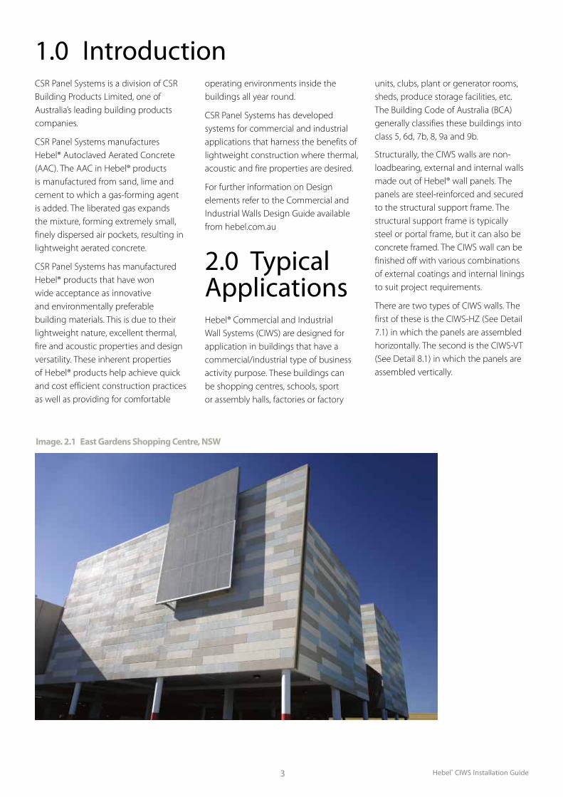
2.0 Typical Applications Hebel® Commercial and Industrial Wall Systems (CIWS) are designed for application in buildings that have a commercial/industrial type of business activity purpose. These buildings can be shopping centres, schools, sport or assembly halls, factories or factory
units, clubs, plant or generator rooms, sheds, produce storage facilities, etc. The Building Code of Australia (BCA) generally classifies these buildings into class 5, 6d, 7b, 8, 9a and 9b.
Structurally, the CIWS walls are non-loadbearing, external and internal walls made out of Hebel® wall panels. The panels are steel-reinforced and secured to the structural support frame. The structural support frame is typically steel or portal frame, but it can also be concrete framed. The CIWS wall can be finished off with various combinations of external coatings and internal linings to suit project requirements.
There are two types of CIWS walls. The first of these is the CIWS-HZ (See Detail 7.1) in which the panels are assembled horizontally. The second is the CIWS-VT (See Detail 8.1) in which the panels are assembled vertically.
Image. 2.1 East Gardens Shopping Centre, NSW
Hebel® CIWS Installation Guide 4
3.4 Hebel® AdhesiveFig. 3.3 Hebel® Adhesive
Hebel® Adhesive (supplied in 20kg bag) is used for gluing the panels together at vertical and horizontal joints.
3.0 System Components 3.1 General System ComponentsA summary of the components or their equivalents that Hebel® recommends for use in the CIWS is shown in Table 3.1.
System component
CIWS Type Supplied by CSR Panel
SystemsCIWS-HZ CIWS-VT
Hebel® Wall Panel 3 3 3
Hebel® Adhesive 3 31 3
Hebel® Mortar 32 32 3
Hebel® Patch 32 32 3
Anticorrosion Coating Agent 32 32 3
DPC or Bond Breaker 32 32
Steel Base Angle 32 32
Fasteners/Fixings 3 3 33
Fire/Acoustic Sealants 3 3
Gyprock™ Plasterboard 31 31
Coating Systems 31 31
Hebel® HighBuild 31 31 3Note: 1 Optional use as specified by project consultants.2 Use as required.3 Some fixings can be supplied by CSR Panel Systems.
3.2 Hebel® Wall Panel
100-300mm panel
thickness
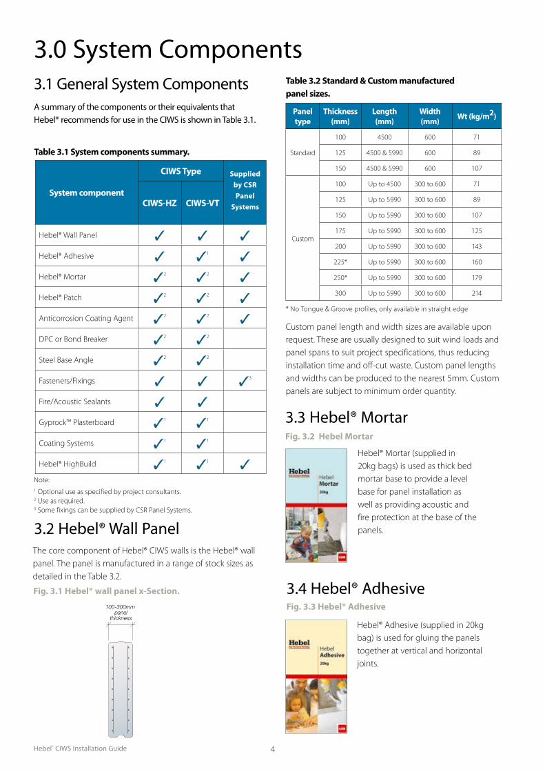
Table 3.2 Standard & Custom manufactured panel sizes.
Panel type
Thickness (mm)
Length (mm)
Width (mm) Wt (kg/m2)
Standard
100 4500 600 71
125 4500 & 5990 600 89
150 4500 & 5990 600 107
Custom
100 Up to 4500 300 to 600 71
125 Up to 5990 300 to 600 89
150 Up to 5990 300 to 600 107
175 Up to 5990 300 to 600 125
200 Up to 5990 300 to 600 143
225* Up to 5990 300 to 600 160
250* Up to 5990 300 to 600 179
300 Up to 5990 300 to 600 214
Custom panel length and width sizes are available upon request. These are usually designed to suit wind loads and panel spans to suit project specifications, thus reducing installation time and off-cut waste. Custom panel lengths and widths can be produced to the nearest 5mm. Custom panels are subject to minimum order quantity.
Fig. 3.1 Hebel® wall panel x-Section.
The core component of Hebel® CIWS walls is the Hebel® wall panel. The panel is manufactured in a range of stock sizes as detailed in the Table 3.2.
Table 3.1 System components summary.
3.3 Hebel® MortarFig. 3.2 Hebel Mortar
Hebel® Mortar (supplied in 20kg bags) is used as thick bed mortar base to provide a level base for panel installation as well as providing acoustic and fire protection at the base of the panels.
* No Tongue & Groove profiles, only available in straight edge
Hebel® CIWS Installation Guide5
3.7 Gyprock™ PlasterboardHebel® CIWS walls can be lined with Gyprock™ Plasterboard on the internal side of the wall if constructing office space or other such areas of the building. The type, thickness and densities of plasterboard will be as per project specifications. Additional information on the Gyprock™ Plasterboard is available through Gyprock™.
3.8 External Finishes
External finishes can be rendered systems or different types of coating systems. The manufacturer of the external finishes
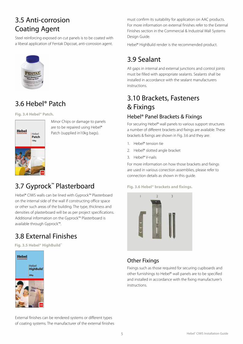
3.5 Anti-corrosion Coating AgentSteel reinforcing exposed on cut panels is to be coated with a liberal application of Fentak Dipcoat, anti-corrosion agent.
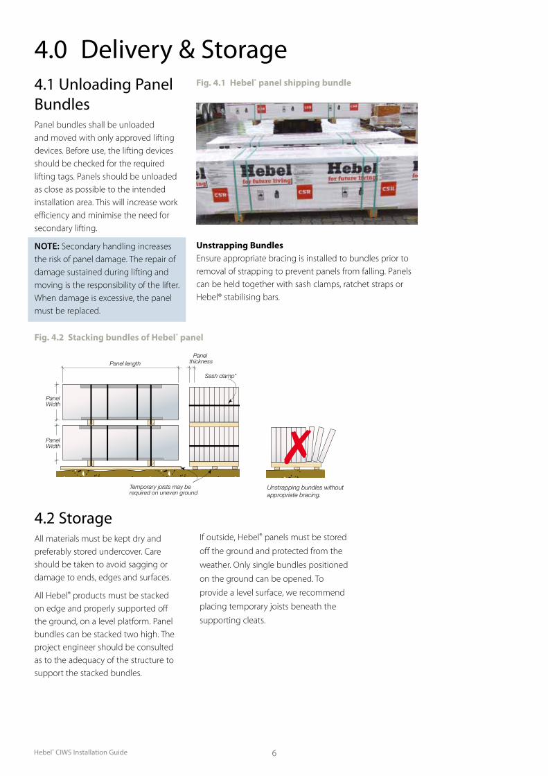
3.6 Hebel® PatchFig. 3.4 Hebel® Patch.
Minor Chips or damage to panels are to be repaired using Hebel® Patch (supplied in10kg bags).
Other FixingsFixings such as those required for securing cupboards and other furnishings to Hebel® wall panels are to be specified and installed in accordance with the fixing manufacturer’s instructions.
must confirm its suitability for application on AAC products. For more information on external finishes refer to the External Finishes section in the Commercial & Industrial Wall Systems Design Guide.
Hebel® HighBuild render is the recommended product.
3.9 SealantAll gaps in internal and external junctions and control joints must be filled with appropriate sealants. Sealants shall be installed in accordance with the sealant manufacturers instructions.
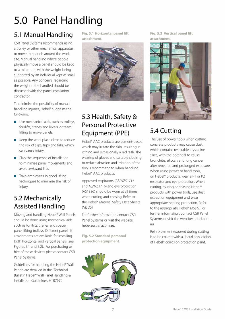
3.10 Brackets, Fasteners & FixingsHebel® Panel Brackets & FixingsFor securing Hebel® wall panels to various support structures a number of different brackets and fixings are available. These brackets & fixings are shown in Fig. 3.6 and they are:
1. Hebel® tension tie
2. Hebel® slotted angle bracket
3. Hebel® V-nails
For more information on how those brackets and fixings are used in various conection assemblies, please refer to connection details as shown in this guide.
Fig. 3.6 Hebel® brackets and fixings.
Fig. 3.5 Hebel® HighBuild™
1 2 3
Hebel® CIWS Installation Guide 6
4.1 Unloading Panel BundlesPanel bundles shall be unloaded and moved with only approved lifting devices. Before use, the lifting devices should be checked for the required lifting tags. Panels should be unloaded as close as possible to the intended installation area. This will increase work efficiency and minimise the need for secondary lifting.
NOTE: Secondary handling increases the risk of panel damage. The repair of damage sustained during lifting and moving is the responsibility of the lifter. When damage is excessive, the panel must be replaced.
4.2 StorageAll materials must be kept dry and preferably stored undercover. Care should be taken to avoid sagging or damage to ends, edges and surfaces.
All Hebel® products must be stacked on edge and properly supported off the ground, on a level platform. Panel bundles can be stacked two high. The project engineer should be consulted as to the adequacy of the structure to support the stacked bundles.
If outside, Hebel® panels must be stored
off the ground and protected from the
weather. Only single bundles positioned
on the ground can be opened. To
provide a level surface, we recommend
placing temporary joists beneath the
supporting cleats.
4.0 Delivery & Storage
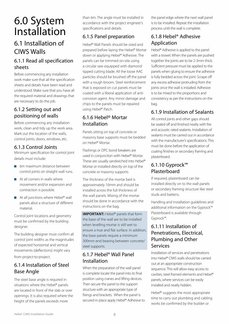
Fig. 4.2 Stacking bundles of Hebel® panel
Temporary joists may be required on uneven ground
Sash clamp*
Panel lengthPanel
thickness
PanelWidth
PanelWidth
Unstrapping bundles without appropriate bracing.
Unstrapping BundlesEnsure appropriate bracing is installed to bundles prior to removal of strapping to prevent panels from falling. Panels can be held together with sash clamps, ratchet straps or Hebel® stabilising bars.
Fig. 4.1 Hebel® panel shipping bundle
Hebel® CIWS Installation Guide7
5.0 Panel Handling5.1 Manual HandlingCSR Panel Systems recommends using a trolley or other mechanical apparatus to move the panels around the work site. Manual handling where people physically move a panel should be kept to a minimum, with the weight being supported by an individual kept as small as possible. Any concerns regarding the weight to be handled should be discussed with the panel installation contractor.
To minimise the possibility of manual handling injuries, Hebel® suggests the following:
Use mechanical aids, such as trolleys, forklifts, cranes and levers, or team lifting to move panels.
Keep the work place clean to reduce the risk of slips, trips and falls, which can cause injury.
Plan the sequence of installation to minimise panel movements and avoid awkward lifts.
Train employees in good lifting techniques to minimise the risk of injury.
5.2 Mechanically Assisted HandlingMoving and handling Hebel® Wall Panels should be done using mechanical aids such us forklifts, cranes and special panel lifting trolleys. Different panel lift attachments are available for installing both horizontal and vertical panels (see Figures 5.1 and 5.2). For purchasing or hire of these devices please contact CSR Panel Systems.
Guidelines for handling the Hebel® Wall Panels are detailed in the “Technical Bulletin Hebel® Wall Panel Handling & Installation Guidelines, HTB799”.
Fig. 5.1 Horizontal panel lift attachment.
Fig. 5.3 Vertical panel lift attachment.
Fig. 5.2 Standard personal protection equipment.
5.3 Health, Safety & Personal Protective Equipment (PPE)Hebel® AAC products are cement-based, which may irritate the skin, resulting in itching and occasionally a red rash. The wearing of gloves and suitable clothing to reduce abrasion and irritation of the skin is recommended when handling Hebel® AAC products.
Approved respirators (AS/NZS1715 and AS/NZ1716) and eye protection (AS1336) should be worn at all times when cutting and chasing. Refer to the Hebel® Material Safety Data Sheets (MSDS).
For further information contact CSR Panel Systems or visit the website, hebelaustraliacom.au.
5.4 CuttingThe use of power tools when cutting concrete products may cause dust, which contains respirable crystalline silica, with the potential to cause bronchitis, silicosis and lung cancer after repeated and prolonged exposure. When using power or hand tools, on Hebel® products, wear a P1 or P2 respirator and eye protection. When cutting, routing or chasing Hebel® products with power tools, use dust extraction equipment and wear appropriate hearing protection. Refer to the appropriate Hebel® MSDS. For further information, contact CSR Panel Systems or visit the website: hebel.com.au
Reinforcement exposed during cutting is to be coated with a liberal application of Hebel® corrosion protection paint.
Hebel® CIWS Installation Guide 8
6.0 System Installation6.1 Installation of CIWS Walls6.1.1 Read all specification sheetsBefore commencing any installation work make sure that all the specification sheets and details have been read and understood. Make sure that you have all the required material and drawings that are necessary to do the job.
6.1.2 Setting out and positioning of wallsBefore commencing any installation work, clean and tidy up the work area. Mark out the location of the walls, control joints, doors, windows, etc.
6.1.3 Control JointsMinimum specification for control joint
details must include:
6m maximum distance between control joints on straight wall runs.
At all corners in walls where movement and/or expansion and contraction is possible.
At all junctions where Hebel® wall panels abut a structure of different material.
Control joint locations and geometry must be confirmed by the building designer.
The building designer must confirm all control joint widths as the magnitudes of expected horizontal and vertical movements (deflections) might vary
from project-to-project.
6.1.4 Installation of Steel Base AngleThe steel base angle is required in situations where the Hebel® panels are located in front of the slab or over openings. It is also required where the height of the panels exceeds more
than 6m. The angle must be installed in accordance with the project engineer’s specifications and details.
6.1.5 Panel preparation Hebel® Wall Panels should be sized and prepared before laying the Hebel® Mortar down or applying Hebel® Adhesive. The panels can be trimmed on-site using a circular saw equipped with diamond tipped cutting blade. All the loose AAC particles should be brushed off the panel with a rough broom. Steel reinforcement that is exposed on cut panels must be coated with a liberal application of anti-corrosion agent. Any minor damage and chips to the panels must be repaired using Hebel® Patch.
6.1.6 Hebel® Mortar Installation
Panels sitting on top of concrete or masonry base supports must be bedded on Hebel® Mortar.
Flashings or DPC bond breakers are used in conjunction with Hebel® Mortar. These are usually sandwiched into Hebel® Mortar or installed directly on top of the concrete or masonry supports.
The thickness of the mortar bed is approximately 10mm and should be installed across the full thickness of the wall panels. Mixing of the mortar should be done in accordance with the instructions on the bag.
IMPORTANT: Hebel® panels that form the base of the wall are to be installed when levelling mortar is still wet to ensure a true and flat surface. In addition, the base panels require a minimum 300mm end bearing between concrete/steel supports.
6.1.7 Hebel® Wall Panel InstallationWhen the preparation of the wall panel is complete locate the panel into its final position using cranes and lifting devices. Then secure the panel to the support structure with an appropriate type of fixings and brackets. When the panel is secured in place apply Hebel® Adhesive to
the panel edge where the next wall panel is to be installed. Repeat the installation process until the wall is complete.
6.1.8 Hebel® Adhesive ApplicationHebel® Adhesive is applied to the panel with a trowel. When the panels are pushed together the joints are to be 2-3mm thick. Sufficient pressure must be applied to the panels when gluing to ensure the adhesive is fully bedded across the joint. Scrape off any excess adhesive protruding from the joints once the wall is installed. Adhesive is to be mixed to the proportions and consistency as per the instructions on the bag.
6.1.9 Installation of SealantsAll control joints and other gaps should be sealed off and finished neatly with fire and acoustic rated sealants. Installation of sealants must be carried out in accordance with the manufacturer’s specifications. This must be done before the application of coating finishes or secondary framing and plasterboard.
6.1.10 Gyprock™ Plasterboard If required, plasterboard can be installed directly on to the wall panels or secondary framing structure like steel studs and battens.
Handling and installation guidelines and additional information on the Gyprock™ Plasterboard is available through Gyprock™.
6.1.11 Installation of Penetrations, Electrical, Plumbing and Other ServicesInstallation of services and penetrations into Hebel® CIWS walls should be carried out at an appropriate construction sequence. This will allow easy access to cavities, steel framed elements and Hebel® panels, where services can be easily installed and neatly hidden.
Hebel® suggests the most appropriate time to carry out plumbing and cabling works be confirmed by the builder or
Hebel® CIWS Installation Guide9
project manager on a project-by-project basis.
Suitable flexible sealants (where required) plus a neat finish for all chasings and penetrations is necessary to maintain the acoustic and fire integrity of the wall.
6.1.12 Application of Coating Finishes
All coating must be applied in accordance with the manufacturer’s specifications. For more information on coatings and coating requirements see the Hebel® High
Performance Coating Systems Brochure. This is available from our website: hebel.com.au
6.1.12 Installation of Fasteners & FixingsAll non-Hebel® fixings and fasteners such as those used for attaching shelves and furnishing should be installed in accordance with the manufacturers specifications.
All brackets and fixings used for securing Hebel® Wall Panels to the support structure should be specified by the
project engineer. Installation of these brackets & fixing to be in accordance with the manufacturer’s or project engineer’s instructions.
The Hebel® Fixing Guide available as part of the Hebel® Technical Manual should be used as a reference for approved fixings to AAC. This is available from our website: hebel.com.au
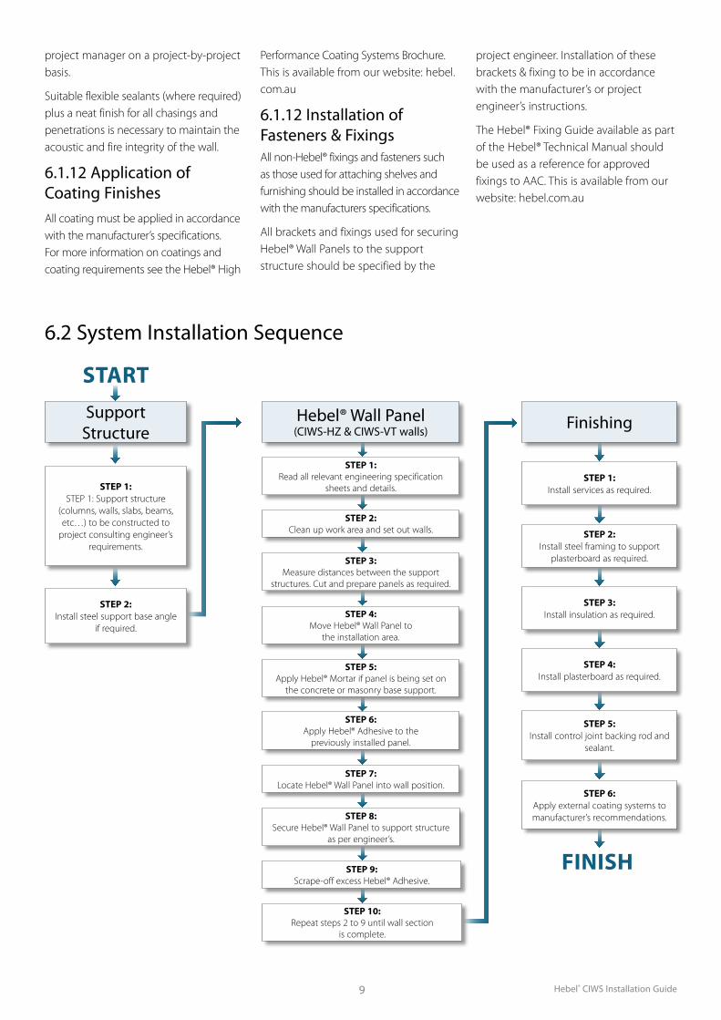
6.2 System Installation Sequence
STARTSupport
Structure
STEP 1: Read all relevant engineering specification
sheets and details.
STEP 2: Clean up work area and set out walls.
STEP 3: Measure distances between the support
structures. Cut and prepare panels as required.
STEP 5: Apply Hebel® Mortar if panel is being set on
the concrete or masonry base support.
STEP 6: Apply Hebel® Adhesive to the
previously installed panel.
STEP 4: Move Hebel® Wall Panel to
the installation area.
STEP 7: Locate Hebel® Wall Panel into wall position.
STEP 8: Secure Hebel® Wall Panel to support structure
as per engineer’s.
STEP 9: Scrape-off excess Hebel® Adhesive.
STEP 10: Repeat steps 2 to 9 until wall section
is complete.
Hebel® Wall Panel (CIWS-HZ & CIWS-VT walls) Finishing
FINISH
STEP 1: Install services as required.
STEP 3: Install insulation as required.
STEP 4: Install plasterboard as required.
STEP 5: Install control joint backing rod and
sealant.
STEP 6: Apply external coating systems to manufacturer’s recommendations.
STEP 1: STEP 1: Support structure
(columns, walls, slabs, beams, etc…) to be constructed to
project consulting engineer’s requirements.
STEP 2: Install steel support base angle
if required.
STEP 2: Install steel framing to support
plasterboard as required.
Hebel® CIWS Installation Guide 10
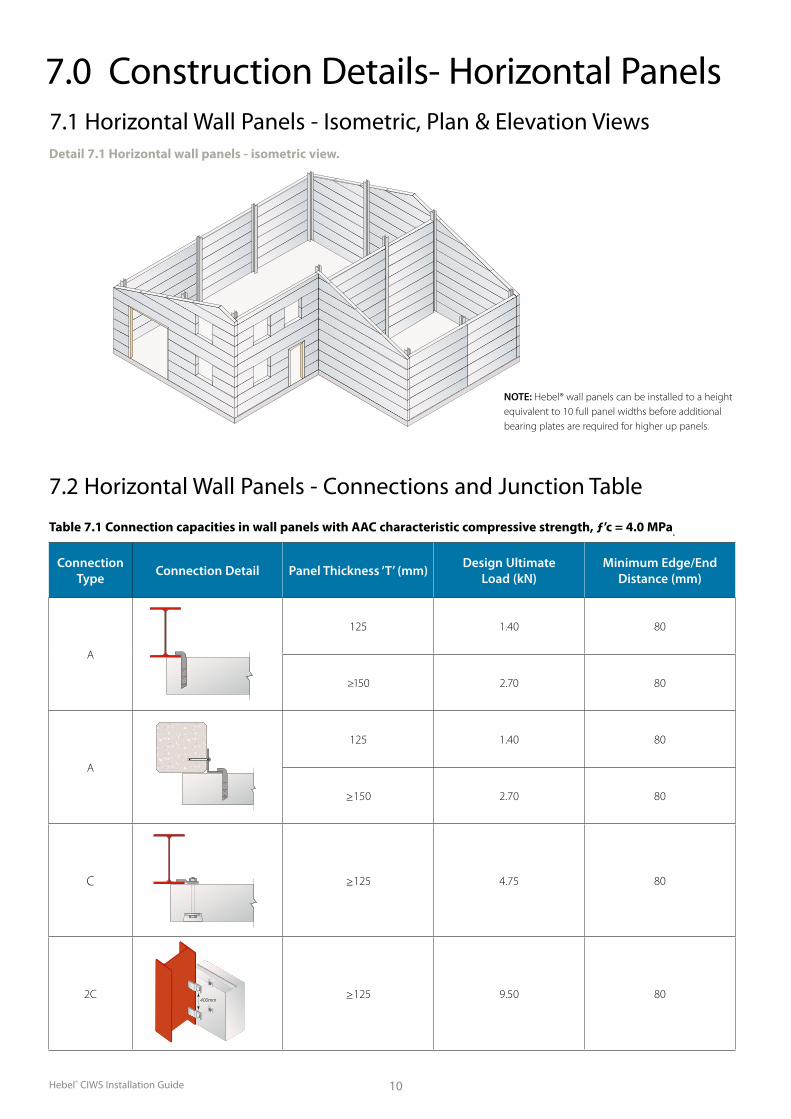
7.0 Construction Details- Horizontal Panels7.1 Horizontal Wall Panels - Isometric, Plan & Elevation ViewsDetail 7.1 Horizontal wall panels - isometric view.
7.2 Horizontal Wall Panels - Connections and Junction Table
Table 7.1 Connection capacities in wall panels with AAC characteristic compressive strength, ƒ’c = 4.0 MPa.
Connection Type Connection Detail Panel Thickness ‘T’ (mm) Design Ultimate
Load (kN)Minimum Edge/End
Distance (mm)
A
125 1.40 80
≥150 2.70 80
A
125 1.40 80
≥150 2.70 80
C ≥125 4.75 80
2C ≥125 9.50 80400mm
NOTE: Hebel® wall panels can be installed to a height equivalent to 10 full panel widths before additional bearing plates are required for higher up panels.
Hebel® CIWS Installation Guide11
Setdown as nominated by others
10m
m 10mm
Hebel ®
horizontal wall panels
= = C L
DPC or equivalent bond breaker & Hebel ® mortar
Drill and grout dowels into concrete/masonry base structure to engineer's specifications
DETAIL 101.1 - HORIZONTAL WALL PANEL & CONCRETE/MASONRY BASE SUPPORT JUNCTION DETAIL
Concrete/masonry base structure
= =
Hebel ® horizontal wall panel
C L
Notch panel neatly to suit
DETAIL 101.2 - HORIZONTAL WALL PANEL & STEEL BASE SUPPORT JUNCTION DETAIL
Steel support details to engineer's specifications
DETAIL 101.3 - HORIZONTAL WALL PANELS STRAIGHT LINE WALL JUNCTION DETAIL
L C
10mm min.
Heb
el®
horiz
onta
lw
all p
anel
to projects specifications Backing rod & sealant
Brackets and fixings of Hebel ® panels to support structure to engineer's specifications
Brackets and fixings of Hebel ® panels to support structure to engineer's specifications
Brackets and fixings of Hebel ® panels to support structure to engineer's specifications
Steel support details to engineer's specifications
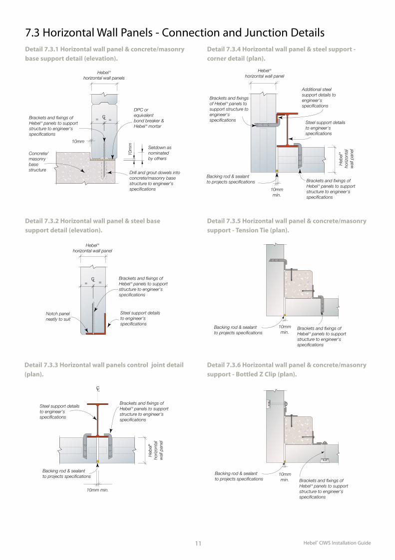
Detail 7.3.1 Horizontal wall panel & concrete/masonry base support detail (elevation).
Detail 7.3.2 Horizontal wall panel & steel base support detail (elevation).
7.3 Horizontal Wall Panels - Connection and Junction Details
Detail 7.3.3 Horizontal wall panels control joint detail (plan).
Setdown as nominated by others
10m
m 10mm
Hebel ®
horizontal wall panels
= = C L
DPC or equivalent bond breaker & Hebel ® mortar
Drill and grout dowels into concrete/masonry base structure to engineer's specifications
DETAIL 101.1 - HORIZONTAL WALL PANEL & CONCRETE/MASONRY BASE SUPPORT JUNCTION DETAIL
Concrete/masonry base structure
= =
Hebel ® horizontal wall panel
C L
Notch panel neatly to suit
DETAIL 101.2 - HORIZONTAL WALL PANEL & STEEL BASE SUPPORT JUNCTION DETAIL
Steel support details to engineer's specifications
DETAIL 101.3 - HORIZONTAL WALL PANELS STRAIGHT LINE WALL JUNCTION DETAIL
L C
10mm min.
Heb
el®
horiz
onta
lw
all p
anel
to projects specifications Backing rod & sealant
Brackets and fixings of Hebel ® panels to support structure to engineer's specifications
Brackets and fixings of Hebel ® panels to support structure to engineer's specifications
Brackets and fixings of Hebel ® panels to support structure to engineer's specifications
Steel support details to engineer's specifications
DETAIL 101.4 - HORIZONTAL WALL PANEL & STEEL SUPPORT - CORNER JUNCTION DETAIL
Hebel ®
horizontal wall panel
Heb
el ®
horiz
onta
lw
all p
anel
Backing rod & sealant to projects specifications
Brackets and fixings of Hebel ® panels to support structure to engineer's specifications
10mm min.
Brackets and fixings of Hebel ® panels to support structure to engineer's specifications
DETAIL 101.5 - HORIZONTAL WALL PANEL & CONCRETE/MASONRY SUPPORT - CORNER JUNCTION DETAIL
10mm min.
Brackets and fixings of Hebel ® panels to support structure to engineer's specifications
Heb
el ®
horiz
onta
l wal
l pan
el
Hebel ®
horizontal wall panel
Concrete/masonry support structure to engineer's specifications
Brackets and fixings of Hebel ® panels to support structure to engineer's specifications
Additional steel support details to engineer's specifications
Steel support details to engineer's specifications
Provide permanant packer between panel & support to suit alignment of panels
Backing rod & sealant to projects specifications
Detail 7.3.4 Horizontal wall panel & steel support - corner detail (plan).
Detail 7.3.5 Horizontal wall panel & concrete/masonry support - Tension Tie (plan).
Detail 7.3.6 Horizontal wall panel & concrete/masonry support - Bottled Z Clip (plan).
10mmmin.
Backing rod & sealant to projects specifications
Brackets and fixings of Hebel ® panels to support structure to engineer's specifications
10mmmin.
Backing rod & sealant to projects specifications Brackets and fixings of
Hebel ® panels to support structure to engineer's specifications
Hebel® CIWS Installation Guide 12
DETAIL 101.8 - HORIZONTAL WALL PANEL & STEEL SUPPORT - PANEL ENDS JUNCTION DETAIL
Heb
el ®
horiz
onta
lw
all p
anel
50mm min. bearing 10mm
packer/packing as required
Non-compressible
to engineer's specifications Steel support details
DETAIL 101.10 - HORIZONTAL WALL PANEL & CONCRETE/MASONRY SUPPORT - PANEL ENDS JUNCTION DETAIL
Heb
el ®
horiz
onta
lw
all p
anel
10mm min.
Concrete/masonary
to engineer's specifications Concrete anchor
support structure to Hebel ® panels toBrackets and fixings of
to projects specifications Backing rod & sealant
support structure to engineer's specifications
to engineer's specifications
Heb
el ®
horiz
onta
lw
all p
anel
50mm min. bearing 10mm nominal gap
DETAIL 101.9 - HORIZONTAL WALL PANEL & STEEL SUPPORT - PANEL ENDS JUNCTION DETAIL
Steel support details to engineer's specifications
nominal gap
Additional steel support details to engineer’s specifications
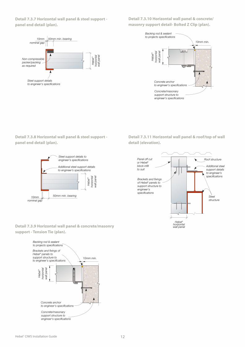
Detail 7.3.7 Horizontal wall panel & steel support - panel end detail (plan).
DETAIL 101.8 - HORIZONTAL WALL PANEL & STEEL SUPPORT - PANEL ENDS JUNCTION DETAIL
Heb
el ®
horiz
onta
lw
all p
anel
50mm min. bearing 10mm
packer/packing as required
Non-compressible
to engineer's specifications Steel support details
DETAIL 101.10 - HORIZONTAL WALL PANEL & CONCRETE/MASONRY SUPPORT - PANEL ENDS JUNCTION DETAIL
Heb
el ®
horiz
onta
lw
all p
anel
10mm min.
Concrete/masonary
to engineer's specifications Concrete anchor
support structure to Hebel ® panels toBrackets and fixings of
to projects specifications Backing rod & sealant
support structure to engineer's specifications
to engineer's specifications
Heb
el ®
horiz
onta
lw
all p
anel
50mm min. bearing 10mm nominal gap
DETAIL 101.9 - HORIZONTAL WALL PANEL & STEEL SUPPORT - PANEL ENDS JUNCTION DETAIL
Steel support details to engineer's specifications
nominal gap
Additional steel support details to engineer’s specifications
Detail 7.3.8 Horizontal wall panel & steel support - panel end detail (plan).
Concrete/masonary
to engineer's specificationsConcrete anchor
support structure to engineer's specifications
10mm min.
Heb
el ®
horiz
onta
lw
all p
anel
to projects specificationsBacking rod & sealant
Detail 7.3.10 Horizontal wall panel & concrete/masonry support detail- Bolted Z Clip (plan).
DETAIL 101.11 - HORIZONTAL WALL PANEL & ROOF/TOP OF WALL SUPPORT STRUCTURE - JUNCTION DETAIL
Hebel®horizontalwall panel
Roof structure
Steel structure
Panel off cut or Hebel® block infill to suit
Brackets and fixings of Hebel® panels to support structure to engineer's specifications
Additional steel support details to engineer’s specifications
Detail 7.3.11 Horizontal wall panel & roof/top of wall detail (elevation).
Detail 7.3.9 Horizontal wall panel & concrete/masonry support - Tension Tie (plan).
10mm min.
to projects specificationsBacking rod & sealant
support structure toHebel ® panels toBrackets and fixings of
to engineer's specifications
Heb
el ®
horiz
onta
lw
all p
anel
Concrete/masonary
to engineer's specificationsConcrete anchor
support structure to engineer's specifications
Hebel® CIWS Installation Guide13
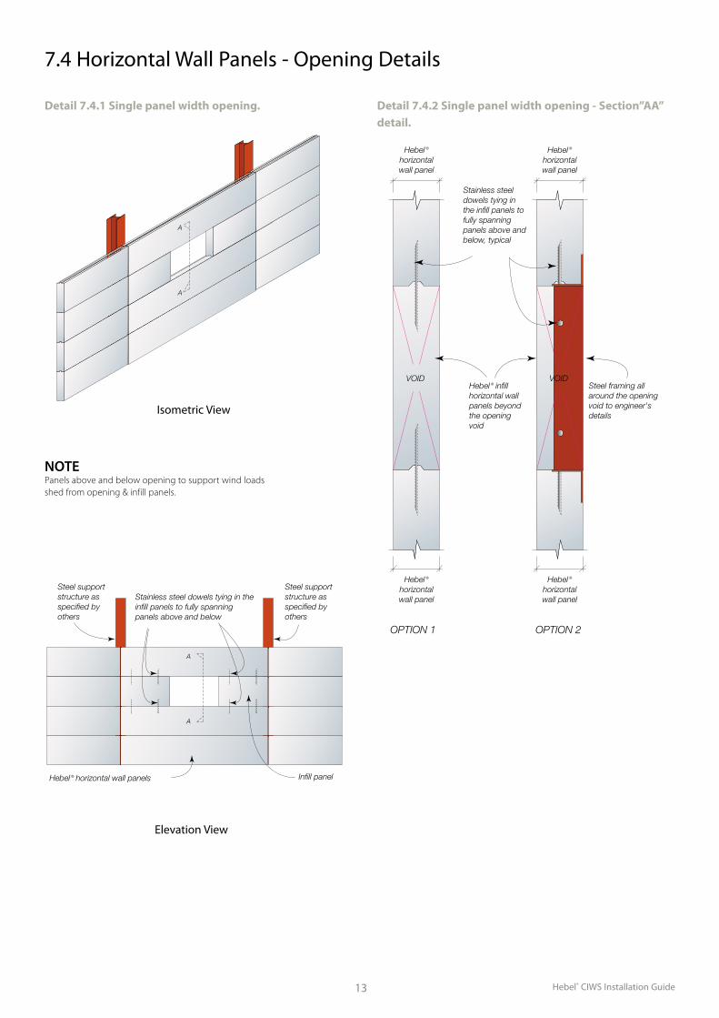
7.4 Horizontal Wall Panels - Opening Details
A
A
DETAIL 102.1.1 - SINGLE PANEL WIDTH OPENING - ISOMETRIC DETAIL
A
A
DETAIL 102.1.2 - SINGLE PANEL WIDTH OPENING - ELEVATION DETAIL
Steel support structure as specified by others
Steel support structure as specified by others
Stainless steel dowels tying in the infill panels to fully spanning panels above and below
Hebel ® horizontal wall panels Infill panel
Note: panels above & below opening to support loads shed from opening & infill panela
Detail 7.4.1 Single panel width opening.
A
A
DETAIL 102.1.1 - SINGLE PANEL WIDTH OPENING - ISOMETRIC DETAIL
A
A
DETAIL 102.1.2 - SINGLE PANEL WIDTH OPENING - ELEVATION DETAIL
Steel support structure as specified by others
Steel support structure as specified by others
Stainless steel dowels tying in the infill panels to fully spanning panels above and below
Hebel ® horizontal wall panels Infill panel
Note: panels above & below opening to support loads shed from opening & infill panela
DETAIL 102.1.3 - SINGLE PANEL WIDTH OPENING - SECTION "AA' DETAIL
VOID
Stainless steel dowels tying in the infill panels to fully spanning panels above and below, typical
VOID
Hebel ®
horizontalwall panel
Hebel ®
horizontalwall panel
Hebel ®
horizontalwall panel
Hebel ®
horizontalwall panel
Steel framing all around the opening void to engineer's details
Hebel ® infill horizontal wall panels beyond the opening void
OPTION 1 OPTION 2
Detail 7.4.2 Single panel width opening - Section”AA” detail.
NOTE Panels above and below opening to support wind loads shed from opening & infill panels.
Isometric View
Elevation View
Hebel® CIWS Installation Guide 14
A
A
DETAIL 102.2.1 - MULTIPLE PANEL WIDTH OPENING - ISOMETRIC DETAIL
DETAIL 102.2.2 - MULTIPLE PANEL WIDTH OPENING - ELEVATION DETAIL
Additional steel support structure fixed to main structure as specified by others
Main structure as specified by others
Stainless steel dowels tying in the infill panels to fully spanning panels above and below
Hebel ® horizontal wall panels
Note: steel support structure to transfer loads from opening & infill Panels to main structure. Steel support structure specified by others
A
A
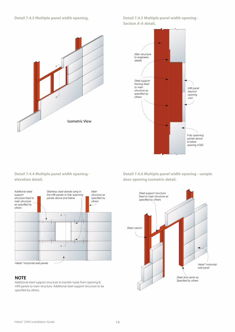
Detail 7.4.3 Multiple panel width opening.
Detail 7.4.4 Multiple panel width opening - elevation detail.
A
A
DETAIL 102.2.1 - MULTIPLE PANEL WIDTH OPENING - ISOMETRIC DETAIL
DETAIL 102.2.2 - MULTIPLE PANEL WIDTH OPENING - ELEVATION DETAIL
Additional steel support structure fixed to main structure as specified by others
Main structure as specified by others
Stainless steel dowels tying in the infill panels to fully spanning panels above and below
Hebel ® horizontal wall panels
Note: steel support structure to transfer loads from opening & infill Panels to main structure. Steel support structure specified by others
A
A
DETAIL 102.2.3 - MULTIPLE PANEL WIDTH OPENING - SECTION A-A DETAIL
Fully spanning panels above & below opening VOID
to engineers details
Main structure
Infill panel beyondopening void
Steel support framing fixed to main structure as specified by others
DETAIL 102.2.4 - MULTIPLE PANEL WIDTH OPENING - SAMPLE DOOR OPENING ISOMETRIC DETAIL
wall panelHebel ® horizontal
Steel column
Specified by others Steel door jamb as
Steel support structure fixed to main structure as specified by others
Detail 7.4.5 Multiple panel width opening - Section A-A detail.
Detail 7.4.6 Multiple panel width opening - sample door opening isometric detail.
NOTE Additional steel support structure to transfer loads from opening & infill panels to main structure. Additional steel support structure to be specified by others.
Isometric View
Hebel® CIWS Installation Guide15
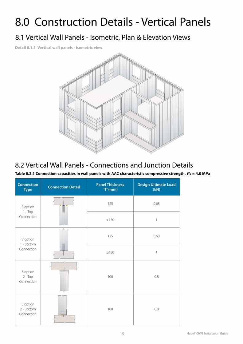
Connection Type Connection Detail Panel Thickness
‘T’ (mm)Design Ultimate Load
(kN)
B option 1 - Top
Connection
125 0.68
≥150 1
B option 1 - Bottom Connection
125 0.68
≥150 1
B option 2 - Top
Connection100 0.8
B option 2 - Bottom Connection
100 0.8
8.0 Construction Details - Vertical Panels8.1 Vertical Wall Panels - Isometric, Plan & Elevation ViewsDetail 8.1.1 Vertical wall panels - isometric view
Table 8.2.1 Connection capacities in wall panels with AAC characteristic compressive strength, ƒ’c = 4.0 MPa.
8.2 Vertical Wall Panels - Connections and Junction Details
Hebel® CIWS Installation Guide 16
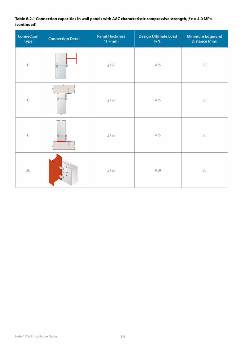
Table 8.2.1 Connection capacities in wall panels with AAC characteristic compressive strength, ƒ’c = 4.0 MPa. (continued)
Connection Type Connection Detail Panel Thickness
‘T’ (mm)Design Ultimate Load
(kN)
C ≥125 4.75
C ≥125 4.75
C ≥125 4.75
2C ≥125 9.50400mm
Minimum Edge/End Distance (mm)
80
80
80
80
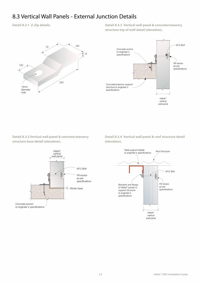
Hebel® CIWS Installation Guide17
Detail 8.3.2 Vertical wall panel & concrete/masonry structure base detail (elevation).
DETAIL 201.7 - VERTICAL WALL PANELS & CONCRETE/MASONRY SUPPORT
STRUCTURE TOP OF WALL JUNCTION DETAIL
JUNCTION DETAIL
DETAIL 201.8 - VERTICAL WALL PANELS & ROOF STRUCTURE
Hebel ®
verticalwall panel
to engineer's specifications Steel support details Roof structure
M12 Bolt
as per specifications
Fill recess
Brackets and fixings of Hebel ® panels to support structure to engineer's specifications
Hebel ®
verticalwall panel
15m
m
max
.
to project specifications Backing rod & sealant
Concrete slab/beam
to engineer's specifications
Concrete anchor
Brackets and fixings of Hebel ® panels to support structure to engineer's specifications
Detail 8.3.4 Vertical wall panel & roof structure detail (elevation).
Detail 8.3.3 Vertical wall panel & concrete/masonry structure top of wall detail (elevation).
Detail 8.3.1 Z clip details.
Hebel ®
verticalwall panel
as per specifications
Fill recess
M12 Bolt
Concrete/masonry support structure to engineer's specifications
to engineer's specifications
Concrete anchor100
12
255
120
14mm Diameter Hole
70
Hebel ®vertical
wall panel
as per specifications
Mortar base
Fill recess
to engineer's specificationsConcrete anchor
M12 Bolt
8.3 Vertical Wall Panels - External Junction Details
Hebel® CIWS Installation Guide 18
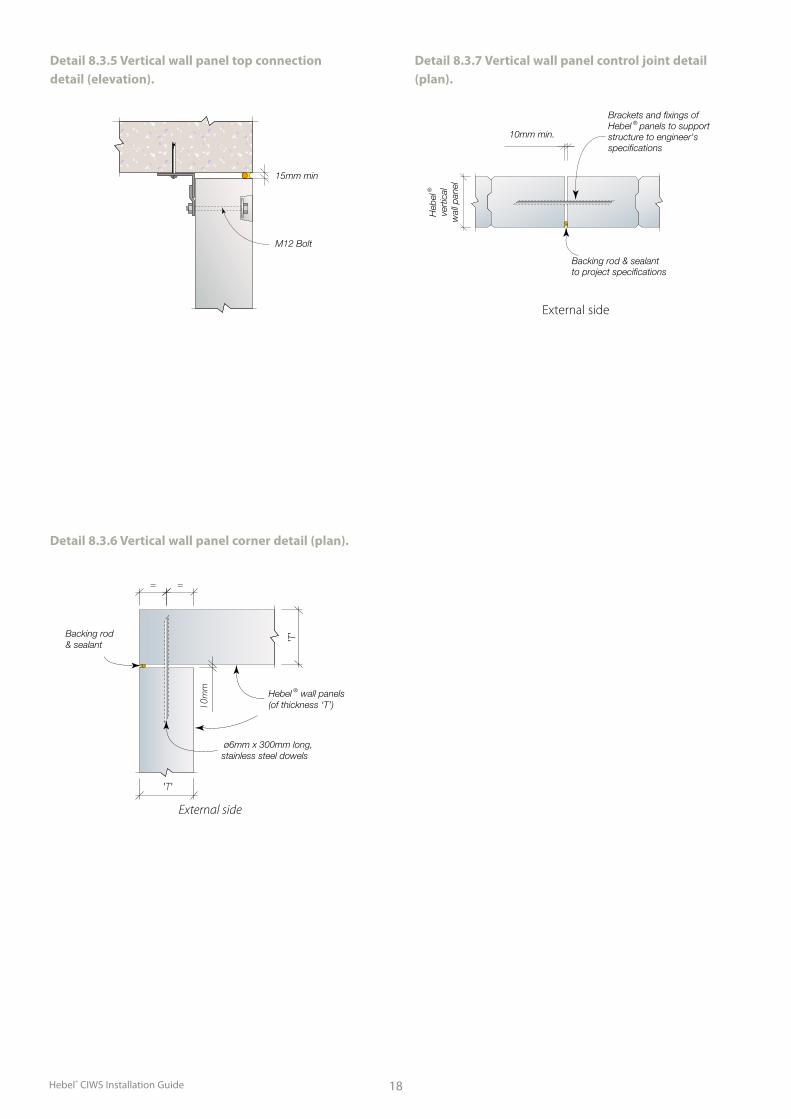
Detail 8.3.6 Vertical wall panel corner detail (plan).
Detail 8.3.5 Vertical wall panel top connection detail (elevation).
DETAIL 201.3 - VERTICAL WALL PANELS SPLAY CORNER
JUNCTION DETAIL
JUNCTION DETAIL
DETAIL 201.4 - VERTICAL WALL PANEL STRAIGHT LINE CONTROL JOINT
Hebel
®
vertic
al
wall p
anel
Heb
el ®
vert
ical
wal
l pan
el
10mm min.
Heb
el ®
vert
ical
wal
l pan
el
to project specificationsBacking rod & sealant
specifications sealant to project Backing rod &
Panel ends to be mitre cut on site to accomodate splay angle arrangement
Brackets and fixings of Hebel ® panels to support structure to engineer's specifications
Brackets and fixings of Hebel ® panels to support structure to engineer's specifications
Detail 8.3.7 Vertical wall panel control joint detail (plan).
Hebel ® wall panels(of thickness ‘T’)
ø6mm x 300mm long, stainless steel dowels
Backing rod & sealant
External side
External side
15mm min
M12 Bolt
Hebel® CIWS Installation Guide19
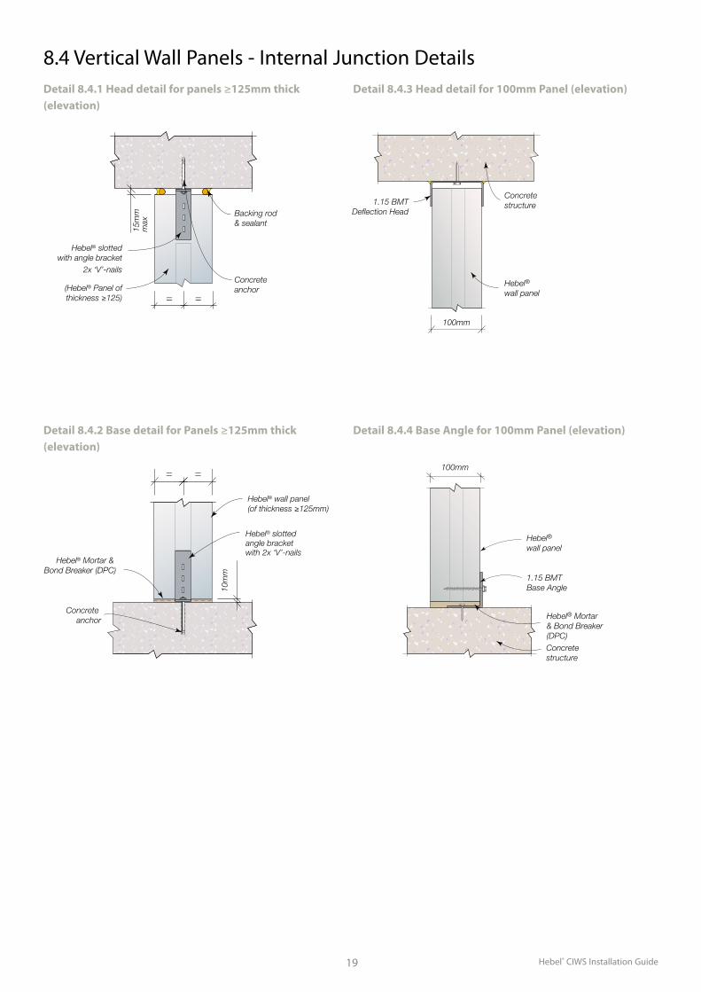
Hebel® slotted with angle bracket
2x ‘V’-nails
(Hebel® Panel of thickness ≥125)
Backing rod & sealant
Concrete anchor
15m
mm
axConcrete structure
Concrete structure1.15 BMT
Deflection Head
100mm
Steelsupport
angle
10m
m
80m
mm
in.
30mmmax.
M12 4.6/S galvanised bolt & 50x50x3mm washer
Hebel® wall panel (of thickness ‘T’)
Hebel® wall panel
8.4 Vertical Wall Panels - Internal Junction DetailsDetail 8.4.1 Head detail for panels ≥125mm thick (elevation)
Detail 8.4.3 Head detail for 100mm Panel (elevation)
Hebel® wall panel (of thickness ≥125mm)
10m
m
Concrete anchor
Hebel® Mortar & Bond Breaker (DPC)
Hebel® slotted angle bracket with 2x ‘V’-nails
Detail 8.4.2 Base detail for Panels ≥125mm thick (elevation)
Concrete structure
Concreteanchor Hebel® Mortar & Bond
Breaker (DPC)
Concrete structure
Hebel® Mortar & Bond Breaker (DPC)
M12 4.6/S galvanised bolt & 50x50x3mm washer
Hebel® wall panel
Hebel® wall panel
1.15 BMT Base Angle
Steelsupport
angle
100mm
Detail 8.4.4 Base Angle for 100mm Panel (elevation)
Hebel® CIWS Installation Guide 20
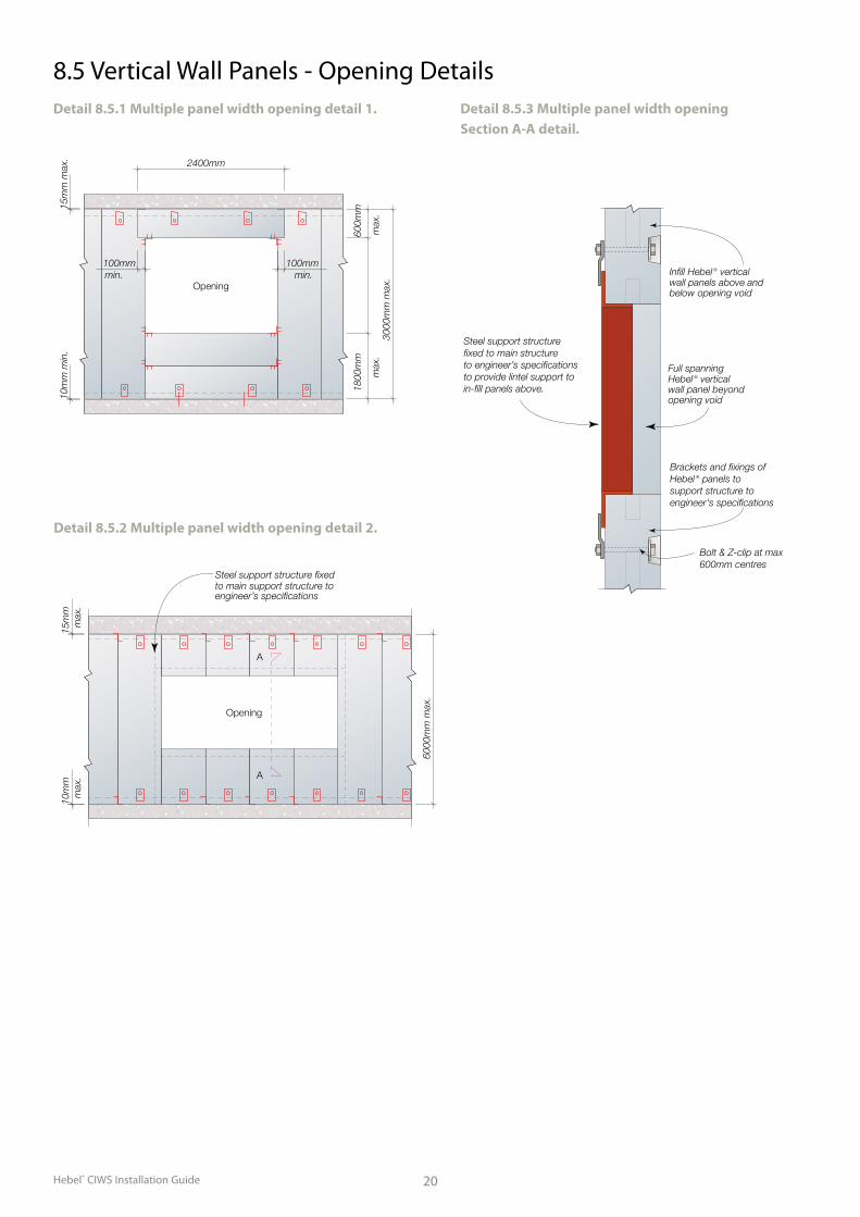
DETAIL 202.4 - MULTIPLE PANEL WIDTH OPENING - SECTION A-A DETAIL
below opening void wall panels above and Infill Hebel ® vertical
Brackets and fixings of Hebel ® panels to support structure to engineer's specifications
Steel support structurefixed to main structureto engineer’s specifications to provide lintel support to in-fill panels above.
Bolt & Z-clip at max 600mm centres
Full spanning Hebel ® verticalwall panel beyond opening void
6000
mm
max
.
10m
m
15m
m
Opening
DETAIL 202.3 - MULTIPLE PANEL WIDTH OPENING DETAIL-2
max
. m
ax.
engineer’s specifications to main support structure to Steel support structure fixed
A
A
Legend:AB = Angle bracket, ref to detailsBR = Backing rod & sealant to project specificationsCS = Concrete support slab/beam/wallEAB = Hebel ® Equal Angle BracketHA = Hebel AdhesiveHWP = Hebel ® horizontal wall panelsHM = DPC or equivalent bond breaker & Hebel ® MortarLP = Hebel ® horizontal lintel panelPB = Hebel ® plate bracketSAB = Slotted angle bracket, ref to detailsSSD = Stainless steel dowels, ref to detailsVWP = Hebel ® vertical wall panelDetail 8.5.2 Multiple panel width opening detail 2.
Detail 8.5.1 Multiple panel width opening detail 1.
DETAIL 202.4 - MULTIPLE PANEL WIDTH OPENING - SECTION A-A DETAIL
below opening void wall panels above and Infill Hebel ® vertical
Brackets and fixings of Hebel ® panels to support structure to engineer's specifications
Steel support structurefixed to main structureto engineer’s specifications to provide lintel support to in-fill panels above.
Bolt & Z-clip at max 600mm centres
Full spanning Hebel ® verticalwall panel beyond opening void
6000
mm
max
.
10m
m
15m
m
Opening
DETAIL 202.3 - MULTIPLE PANEL WIDTH OPENING DETAIL-2
max
. m
ax.
engineer’s specifications to main support structure to Steel support structure fixed
A
A
Legend:AB = Angle bracket, ref to detailsBR = Backing rod & sealant to project specificationsCS = Concrete support slab/beam/wallEAB = Hebel ® Equal Angle BracketHA = Hebel AdhesiveHWP = Hebel ® horizontal wall panelsHM = DPC or equivalent bond breaker & Hebel ® MortarLP = Hebel ® horizontal lintel panelPB = Hebel ® plate bracketSAB = Slotted angle bracket, ref to detailsSSD = Stainless steel dowels, ref to detailsVWP = Hebel ® vertical wall panel
Detail 8.5.3 Multiple panel width opening Section A-A detail.
8.5 Vertical Wall Panels - Opening Details
Hebel® CIWS Installation Guide21
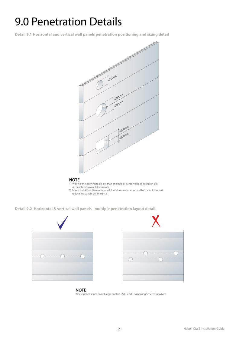
9.0 Penetration Details
DETAIL 4.1 - HORIZONTAL AND VERTICAL WALL PANELS PENETRATION POSITIONING AND SIZING DETAIL
NOTE 1) Width of the opening to be less than one third of panel width, to be cut on site. All panels shown are 600mm wide.2) Notch should not be overcut as additional reinforcement could be cut which would reduce the panel's performance.
<200mm
<200mm
<200mm
<200mm
<200mm
NOTE Where penetrations do not align, contact CSR Hebel Engineering Services for advice
DETAIL 4.2 - HORIZONTAL AND VERTICAL WALL PANELS MULTIPLE PENETRATION LAYOUT DETAIL
Detail 9.1 Horizontal and vertical wall panels penetration positioning and sizing detail
DETAIL 4.1 - HORIZONTAL AND VERTICAL WALL PANELS PENETRATION
POSITIONING AND SIZING DETAIL
NOTE 1) Width of the opening to be less than one third of panel width, to be cut on site. All panels shown are 600mm wide.2) Notch should not be overcut as additional reinforcement could be cut which would reduce the panel's performance.
<200mm
<200mm
<200mm
<200mm
<200mm
NOTE Where penetrations do not align, contact CSR Hebel Engineering Services for advice
DETAIL 4.2 - HORIZONTAL AND VERTICAL WALL PANELS MULTIPLE PENETRATION LAYOUT DETAIL
Detail 9.2 Horizontal & vertical wall panels - multiple penetration layout detail.
22
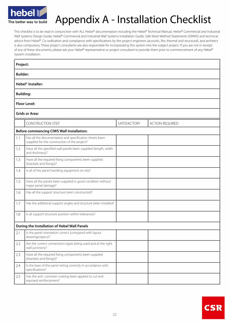
Appendix A - Installation ChecklistThis checklist is to be read in conjunction with ALL Hebel® documentation including the Hebel® Technical Manual, Hebel® Commercial and Industrial Wall Systems Design Guide, Hebel® Commercial and Industrial Wall Systems Installation Guide, Safe Work Method Statements (SWMS) and technical advice from Hebel®. Co-ordination and compliance with specifications by the project engineers (acoustic, fire, thermal and structural), and architectis also compulsory. These project consultants are also responsible for incorporating this system into the subject project. If you are not in receipt of any of these documents, please ask your Hebel® representative or project consultant to provide them prior to commencement of any Hebel®System installation.
Project:
Builder:
Hebel® Installer:
Building:
Floor Level:
Grids or Area:
CONSTRUCTION STEP SATISFACTORY ACTION REQUIRED
Before commencing CIWS Wall Installation:
1.1 Has all the documentation and specification sheets been supplied for the construction of the project?
1.2 Have all the specified wall panels been supplied (length, width and thickness)?
1.3 Have all the required fixing components been supplied (brackets and fixings)?
1.4 Is all of the panel handling equipment on site?
1.5 Have all the panels been supplied in good condition without major panel damage?
1.6 Has all the support structure been constructed?
1.7 Has the additional support angles and structure been installed?
1.8 Is all support structure position within tolerances?
During the Installation of Hebel Wall Panels
2.1 Is the panel orientation correct (compared with layout drawings/specs)?
2.2 Are the correct connections types being used and at the right wall junctions?
2.3 Have all the required fixing components been supplied (brackets and fixings)?
2.4 Is the base of the panel sitting correctly in accordance with specifications?
2.5 Has the anti- corrosion coating been applied to cut and exposed reinforcement?
Hebel® CIWS Installation Guide23
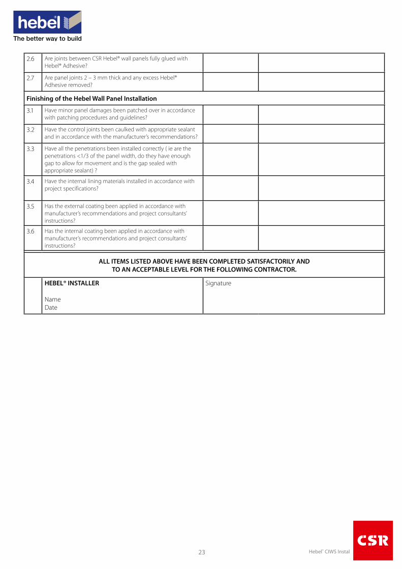
2.6 Are joints between CSR Hebel® wall panels fully glued with Hebel® Adhesive?
2.7 Are panel joints 2 – 3 mm thick and any excess Hebel® Adhesive removed?
Finishing of the Hebel Wall Panel Installation
3.1 Have minor panel damages been patched over in accordance with patching procedures and guidelines?
3.2 Have the control joints been caulked with appropriate sealant and in accordance with the manufacturer’s recommendations?
3.3 Have all the penetrations been installed correctly ( ie are the penetrations <1/3 of the panel width, do they have enough gap to allow for movement and is the gap sealed with appropriate sealant) ?
3.4 Have the internal lining materials installed in accordance with project specifications?
3.5 Has the external coating been applied in accordance with manufacturer’s recommendations and project consultants’ instructions?
3.6 Has the internal coating been applied in accordance with manufacturer’s recommendations and project consultants’ instructions?
ALL ITEMS LISTED ABOVE HAVE BEEN COMPLETED SATISFACTORILY AND TO AN ACCEPTABLE LEVEL FOR THE FOLLOWING CONTRACTOR.
HEBEL® INSTALLER
Name Date
Signature
Available from:
The better way to buildHebel is a quality building product, and is backed by CSR Building Products Limited.
For more information visit our website.
www.hebel.com.auFor sales enquiries or further information, please telephone us from anywhere in Australia:
1300 369 448
Hebel® is a registered trademark of the Xella group. CSR Building Products Ltd is an exclusive licensee of Xella. CSR Hebel is a business of CSR Building Products Ltd ABN 55 008 631 356.
CSR, PowerPanel®, PowerClad®, Hebel Block®, PowerFloor®, Hebel Floor®, PowerFence®, HighBuild®, are registered trademarks of CSR Building Products Limited.
CSR HEBELTriniti 3, 39 Delhi RoadNorth Ryde NSW 2113, AustraliaTelephone +61 2 9235 8000
Health and safetyInformation on any known health risks of our products and how to handle them safely is on product packaging and / or the accompanying documentation.
Additional information is listed in the Material Safety Data Sheet (MSDS). To obtain a copy of a MSDS, download from www.hebel.com.au. Contractors are required by law to perform their own risk assessments before undertaking work.
Performance and certification Hebel® products and systems are developed in Australia by CSR Building Products. ABN. 55 008 631 356. It is a manufacturer and supplier of Hebel Autoclaved Aerated Concrete (AAC) products. Because it is a manufacturer and supplier only, CSR does not employ people qualified as Accredited or Principal Certifiers.
CSR is therefore unable to provide Construction Compliance Certificates or Statements of Compliance. CSR conducts appropriate testing of its products and systems to determine performance levels. These include structural, fire and acoustic tests. Testing is conducted and certified by appropriate specialists in these fields. When using Hebel products and systems in specific projects, such specialists should be consulted to ensure compliance with the Building Code of Australia and relevant Australian Standards.
DisclaimerInformation presented in this document is supplied in good faith and to the best of our knowledge was accurate at the time of preparation. The provision of this information should not be construed as a recommendation to use any of our products in violation of any patent rights or in breach of any statute or regulation. Users are advised to make their own determination as to the suitability of this information in relation to their particular purpose or specific circumstances. Since the information contained in this document may be applied under conditions beyond our control, no responsibility can be accepted by CSR ‚ or its staff for any loss or damage caused by any person acting or refraining from action as a result of misuse of this information.
OtherThe design of a wall, floor or fence system requires the services of professional consultants. This document has been prepared as a source of information to provide general guidance to those consultants – and in no way replaces the services of the professional consultant and relevant engineers designing the project.
No liability can therefore be accepted by CSR or other parties for the use of this document. Hebel products and systems undergo constant research and development to integrate new technology and reflect ongoing performance enhancement.
Hebel systems are constantly reviewed so as to reflect any changes in legislative building requirements and or general developments in common building practice, due to our commitment to continual development and improving our building systems.
We advise that all users of this document should regularly check that this document is current, and they are applying our latest design information.
The latest editions of our documents are available on our website: www.hebel.com.au
HELIT036 October 2015