comminution of porous materials
TRANSCRIPT
mnnmlonm munnm af
rnmEfiuk PROMSlllG
Int. J. Miner. Process. 44-45 ( 1996) 117- 13 I
Comminution of porous materials
P. Bevilacqua, G. Ferrara DICAMP - Process Engineering Division, Unioersify of Trieste, P.le Europa I, 34127 Trieste, Italy
Abstract
The behaviour of porous materials in comminution processes differs substantially from that of non-porous materials. It is strongly affected by the type of porosity, which may be characterized by different void shapes and interconnection degrees. This paper discusses the comminution of porous materials having voids of compact shape (like spheres) and not interconnected. For such materials different behaviours can be expected for the two comminution ranges above and below the mean voids interspace. In fact, for the coarser sizes the mechanical behaviour of the material is that of the porous material defined by its bulk mechanical properties; below the mean voids interspace down to very fine sizes the mechanical behaviour of the material is that of the non-porous material constituting the matrix. Therefore, a transitional region should exist, with the result of bi- or trimodal size distributions for comminuted porous materials.
To verify the above mentioned theory, tests were performed on two types of materials, artificial and natural: (a) perforated bricks with 20 mm voids; (b) natural pumice stone. The resulting size distributions differ in slope above and below the mean voids interspace, and the two parts of the distribution are connected by a transition curve. The results may be of interest in studying the comminution of different types of materials, particularly secondary materials and scraps.
1. Introduction
There exist many, both natural and artificial, porous materials whose behaviour and properties are strongly affected by the presence of voids. In the present paper, only a few aspects of the behaviour of these materials in comminution processes will be discussed.
The topic appears of general interest, since also in materials that are not considered porous voids may be present and affect their behaviour, but they play a particularly important role in the comminution of materials that are specifically considered porous. Typical is the case of materials used as abrasives, e.g. pumice, a natural material extracted in volcanic regions, and silicon carbide, which is a synthetic material. Tbe
0301.7516/96/$15.00 0 1996 Elsevier Science B.V. All rights reserved SSDl 0301-7516(95)00023-2
II8 P. Bevilucqua, G. Ferrurrr/Int. 1. Miner. Process. 44-45 (1996) 117-131
porosity of these materials affects the results of the comminution and classification processes performed to obtain products with the required market specifications.
Another aspect of the problem is the liberation of the voids aimed at modifying the apparent density of the porous material so as to approximate it to the density of the non-porous matrix. This problem arises when two materials, one of which is porous, have to be separated by gravity processes and it is necessary to make the two materials differ in density as much as possible. The problem has been investigated recently by Ferrara et al. (1993) and is of interest for the treatment of scraps and industrial waste and also of minerals containing a porous phase.
Porous materials have been studied in depth as concerns some of their properties in various technical fields. For example, the porosity of rocks has been investigated mostly in connection with their ability of being hydrocarbon reservoirs and with the movement of fluids in the underground. For various types of reservoir rocks, studies have been made on how the compression due to the depth at which the rock lies affects its porosity (Fatt and Davis, 1912). For other materials. the problem of filtration through porous media and other problems related to chemical engineering have been studied. Numerous research works have been devoted to the effect of porosity on the mechanical properties of rocks. Studies are available on the influence of porosity (Toksoz et al., 1976) and the presence of microcracks and fractures (Zimmerman and King, 1985) on the velocity of seismic waves. The effect of porosity on the elastic modulus and the strength properties of rocks have also been investigated (Kowalski, 1966; Dunn et al., 1973; Hoshino, 1974; Budiansky and O’Connel, 1976; Friedman, 1976; Seeburger and Nur, 1984; Zimmer- man, 1984; Price and Bauer, 1985). Other studies on mechanical properties deal with the porous materials used in building, such as the aggregates of expanded slag, clay or schist and the lightweight concrete made up with these aggregates (Amould and Virlogeux, 1986).
In contrast, as far as the present writers know, no specific studies have been published on the effect of porosity on the behaviour of materials in comminution. Because this topic would involve a great number of cases and is a very complex one, the present paper will be confined to a first partial contribution aimed at promoting the discussion and further research work.
2. Porous materials
Porous materials may be classified according to various aspects: e.g., whether they are natural or artificial, what they are used for, where they come from, what their porosity characteristics are as concerns shape, size and interconnection of the pores.
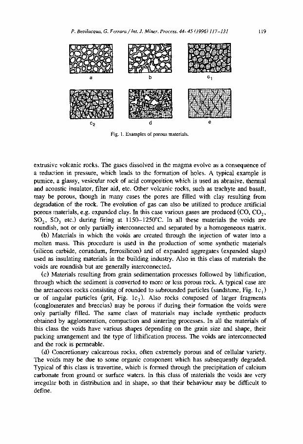
The present paper will deal only with those features which may be more useful for characterizing the behaviour of the materials in comminution. It seems interesting to classify them according to their origin, which is an essential factor in determining the shape and size of the voids. Therefore, the following classification is proposed (Fig. 1 a-e).
(a) Materials in which the voids result from the evolution of gas inside a molten mass. Such phenomena occur in nature and lead to the formation of various types of
P. Bevilacqua, G. Ferrara /ht. .I. Miner. Process. 44-45 (1996) 117-131 119
a b
c2 d e
Fig. 1. Examples of porous materials.
extrusive volcanic rocks. The gases dissolved in the magma evolve as a consequence of a reduction in pressure, which leads to the formation of holes. A typical example is pumice, a glassy, vesicular rock of acid composition which is used as abrasive, thermal and acoustic insulator, filter aid, etc. Other volcanic rocks, such as trachyte and basalt, may be porous, though in many cases the pores are filled with clay resulting from degradation of the rock. The evolution of gas can also be utilized to produce artificial porous materials, e.g. expanded clay. In this case various gases are produced (CO, CO,, SO,, SD, etc.> during firing at 1150-1250°C. In all these materials the voids are roundish, not or only partially interconnected and separated by a homogeneous matrix.
(b) Materials in which the voids are created through the injection of water into a molten mass. This procedure is used in the production of some synthetic materials (silicon carbide, corundum, ferrosilicon) and of expanded aggregates (expanded slags) used as insulating materials in the building industry. Also in this class of materials the voids are roundish but are generally interconnected.
(c) Materials resulting from grain sedimentation processes followed by lithification, through which the sediment is converted to more or less porous rock. A typical case are the arenaceous rocks consisting of rounded to subrounded particles (sandstone, Fig. lc ,) or of angular particles (grit, Fig. lc,). Also rocks composed of larger fragments (conglomerates and breccias) may be porous if during their formation the voids were only partially filled. The same class of materials may include synthetic products obtained by agglomeration, compaction and sintering processes. In all the materials of this class the voids have various shapes depending on the grain size and shape, their packing arrangement and the type of lithification process. The voids are interconnected and the rock is permeable.
(d) Concretionary calcareous rocks, often extremely porous and of cellular variety. The voids may be due to some organic component which has subsequently degraded. Typical of this class is travertine, which is formed through the precipitation of calcium carbonate from ground or surface waters. In this class of materials the voids are very irregular both in distribution and in shape, so that their behaviour may be difficult to define.
120 P. Beuiltcqua, G. Ferraru/Int. J. Miner. Process. 44-45 (19961 117-131
(e) Materials in which the porosity is due to microcracks and fractures resulting from stresses and strains in the rock. The porosity is low, unless there has occurred a dilation or expansion in volume of the particle mass during the fracture formation. This type of porous materials are mentioned here for the sake of completeness, but will not be considered in the following sections.
3. Mechanical behaviour of porous materials
Studies of the mechanical behaviour of porous materials have been made in the field of rock mechanics. For calculations concerning the stability of underground and open pit excavations, the problem is generally simplified by considering the porous materials as a homogeneous material characterized by its bulk properties as determined by tests. However, as already mentioned, several researchers have studied the relationship existing between porosity and mechanical behaviour for particular types of rocks or materials.
The data reported in the literature vary according to the problem studied and to the existence of some particular conditions, e.g. the filling of the pores with fluids. However, some general indications can be given on the influence of porosity on the behaviour of materials.
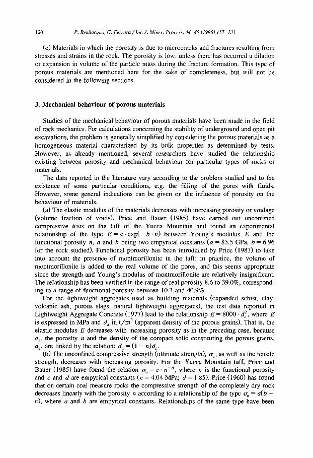
(a) The elastic modulus of the materials decreases with increasing porosity or voidage (volume fraction of voids). Price and Bauer (198.5) have carried out unconfined compressive tests on the tuff of the Yucca Mountain and found an experimental relationship of the type E = a. exp(- b. n) between Young’s modulus E and the functional porosity n, a and b being two empyrical constants (a = 85.5 GPa, b = 6.96 for the rock studied). Functional porosity has been introduced by Price (1983) to take into account the presence of montmorillonite in the tuff: in practice, the volume of montmorillonite is added to the real volume of the pores, and this seems appropriate since the strength and Young’s modulus of montmorillonite are relatively insignificant. The relationship has been verified in the range of real porosity 8.6 to 39.0%, correspond- ing to a range of functional porosity between 10.3 and 40.9%.
For the lightweight aggregates used as building materials (expanded schist, clay, volcanic ash, porous slags, natural lightweight aggregates), the test data reported in Lightweight Aggregate Concrete (1977) lead to the relationship E = 8000. di, where E is expressed in MPa and d, in t/m3 (apparent density of the porous grains). That is, the elastic modulus E decreases with increasing porosity as in the preceding case, because d,, the porosity n and the density of the compact solid constituting the porous grains, d,, are linked by the relation: d, = (1 - n)d,.
(b) The unconfined compressive strength (ultimate strength), a;, as well as the tensile strength, decreases with increasing porosity. For the Yucca Mountain tuff, Price and Bauer (1985) have found the relation a, = c. nmd, where n is the functional porosity and c and d are empyrical constants (c = 4.04 MPa; d = 1.85). Price (1960) has found that on certain coal measure rocks the compressive strength of the completely dry rock decreases linearly with the porosity n according to a relationship of the type a; = a(b - n), where a and b are empyrical constants. Relationships of the same type have been
P. Bevilacqua, G. Ferrara / hr. J. Miner. Process. 44-45 (1996) 117-131 121
found by Gaudon and Struillou (1976) to represent the tensile strength evaluated indirectly by Brazilian tests performed on lightweight aggregates used in the production of building materials. Other data of both compressive and tensile strength of particle assemblages and compacted powders reported by Shinohara (1984) indicate that the strength decreases with increasing porosity or - which is equivalent - with decreasing apparent density of the aggregate.
(c) The coefficient of internal friction decreases as porosity increases. Data reported by Nash (1953) about tests performed on dry or saturated compacted sands have shown that as the porosity increases from 39 to 45% the internal friction angle varies from 41” to 33“. Skempton (1948) has given a graphical representation of the results of numerous tests on cohesive materials that shows the same type of dependence between internal friction angle and porosity. These results are also confirmed by the data reported by Shinohara (1984).
4. The breakage of porous materials
In the modelling of breakage, random comminution - e.g. rupture along isotropic uniform probability Poisson planes as studied by Miles (1969) and Matheron (1972) - is assumed in most cases. Random comminution may be a good assumption in the presence of homogeneous isotropic solids, less good or inadmissible when the material contains voids and pores, fractures or structured preferred orientations.
Cle,uly, any type of anisotropy influences the location of the sites where the cracks start a:s well as the fracture patterns. This is a well-known fact, and some theories on breakage hypothesize the existence of microcracks even for the homogeneous solids from which the fracture should start. In porous materials this role can obviously be played by pores. The pore distribution in the rock may also affect the fracture patterns.
4.1. Choice of the model
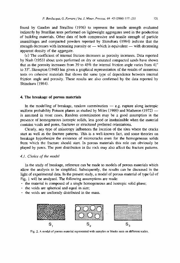
In the study of breakage, reference can be made to models of porous materials which allow the analysis to be simplified. Subsequently, the results can be discussed in the light of experimental data. In the present study, a model of porous material of type (a> of Fig. 1 will be analysed. The following assumptions are made: * the material is composed of a single homogeneous and isotropic solid phase; - the voids are spherical and equal in size; * the voids are uniformly distributed in the mass.
Fig. 2. A model of porous material represented with samples or blocks seen on different scales.
122 P. Beuilacqua, G. Ferrara/lnt. J. Miner. Process. 44-45 (1996) 117-131
In analysing the breakage a scale factor should be introduced. In Fig. 2 the selected model is represented with samples or blocks of the material seen on different scales.
In the large-scale sample, S,, the pores are small in size compared to the mass and uniformly distributed; therefore, the breakage behaviour can be assumed to be that of a homogeneous rock, obviously dependent on the bulk mechanical properties determined on rock samples on the same scale.
In the small-scale sample, S,, the pores are large compared to the mass, which is a fabric composed of voids and a compact matrix. If the mechanical properties of the compact matrix are known, the material S, can be studied by numerical experiments or by photoelasticity in order to ascertain the distribution of stresses, the failure sites and, hence, the fracture patterns.
The microscale sample, S,, is constituted by the homogeneous isotropic compact matrix which is a component of the two preceding samples. This material has mechani- cal properties of its own, different from those of the preceding samples, often difficult to determine when samples large enough for the tests to be performed are not available.
S ,, S, and S, may be considered different materials; in fact, they exibit different behaviour. For example, for the elastic moduli of S, and S, we have E, < E3, The same relationship holds for the shear modulus G, the friction angle 4, the cohesion and the tensile strength a;. Sample S, may exibit an intermediate behaviour if considered as a whole, but when performing the stress analysis of the structure by numerical experi- ments the mechanical properties of the compact matrix, i.e. of S,, are required.
As regards comminution, different behaviours may be expected for the three materi- als in their respective size ranges. It may be assumed that: * both S, in coarse comminution and S, in fine comminution result in different size
distributions, characterized by Gaudin-Schuhmann plots with usually different slopes n, and n,; in general, n, < n,;
. the straight lines representing the two distributions with slopes n, and n3 are joined through a curve which represents the size distribution resulting from the comminution on the scale level of S,;
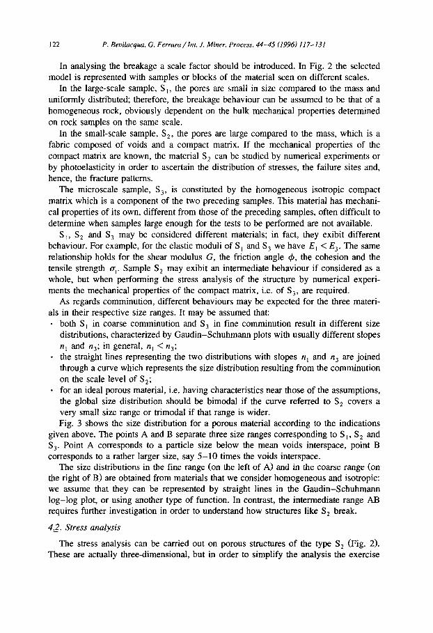
- for an ideal porous material, i.e. having characteristics near those of the assumptions, the global size distribution should be bimodal if the curve referred to S, covers a very small size range or trimodal if that range is wider. Fig. 3 shows the size distribution for a porous material according to the indications
given above. The points A and B separate three size ranges corresponding to S , , S, and S,. Point A corresponds to a particle size below the mean voids interspace, point B corresponds to a rather larger size, say 5-10 times the voids interspace.
The size distributions in the fine range (on the left of A) and in the coarse range (on the right of B) are obtained from materials that we consider homogeneous and isotropic: we assume that they can be represented by straight lines in the Gaudin-Schuhmann log-log plot, or using another type of function. In contrast, the intermediate range Al3 requires further investigation in order to understand how structures like S, break.
42. Stress analysis
The stress analysis can be carried out on porous structures of the type S, (Fig. 2). These are actually three-dimensional, but in order to simplify the analysis the exercise
P. Bevilacqua, G. Ferrara/lnr. J. Miner. Process. 44-45 (1996) 117-131 123
0.01 011 i 10
PuliCk size (mm)
Fig. 3. Typical size distribution of a comminuted porous material.
will be done on two-dimensional structures. Different arrangements of the voids could be analysed: regular and with various slopes of the planes intersecting the voids centres, irregular, with different proportions of voids. The stress analysis can be performed on spherical or cubic particles: in the former case the Brazilian test is simulated, in the latter the uniaxial compression test.
The Brazilian test is more frequently used in single-particle crushing tests. The most important studies have been made by Rumpf et al. (19671, Rumpf and Schijnert (1972), Gildemeister and Schonert (1976) and Schijnert (1973, Schanert (1979) on the failure of spheres of different materials. The same test has been simulated in numerical experi- ments by Clark (1992, Clark (1993) to study the stages in the process of single particle crushing and the role of rock fabric. The compression of cubes between platens has been used by Carey and Bosanquet (1933), Smekel (1938) and by Gaudin and Yavasca (1946). It was observed, however, that the irregularity of the surfaces and the friction force between platen and particle remarkably influenced the tests and even limited their validity (Prasher, 1987).
Because our aim was only to make a computational stress analysis, and consequently the irregularities of the surfaces and the friction force are of no effect, we decided to simulate the compression of cubes or prisms, which in two-dimensional analysis are represented as squares or rectangles.
The boundary element stress analysis was performed using the program Examine 2D-Version 3.1 by Curran and Corkum (1988-91). The material behaviour has been modell’ed using a Mohr-Coulomb elasto-plastic constitutive law with the following properties: Young’s modulus E = 30 GPa, Poisson’s ratio 0.25, friction angle (b = 35”, cohesion c = 12 MPa and tensile strength cut-off a,, = 10 MPa.
The program gives, for different load conditions, the magnitude and direction of the principal stresses (T, and r_rs, the Strength Factor, SF, the displacement vectors and the lines representing contour range boundaries. The Strength Factor is defined as strength/stress ratio: SF = S,,,,,/S, where S and S,,,,, are defined as follows.
v +m3X =ccos4+Psinr$
124 P. Beuilucyua, G. Ferrara/Int. J. Miner. Process. 44-45 (1996) 117-131
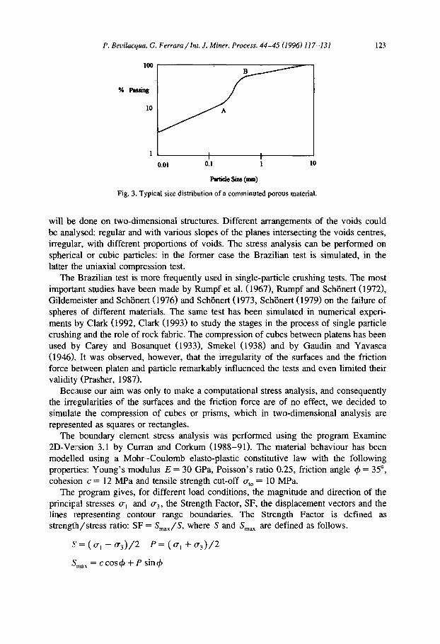
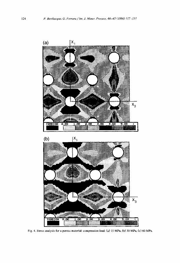
Fig. 4. Stress analysis for a porous material: compression load: (a) 15 MPa, (b) 30 MPa, (c) 60 MPa.
P. Beuilacquu. G. Ferrara/Int. J. Miner. Process. 44-45 (1996) 117-131 125
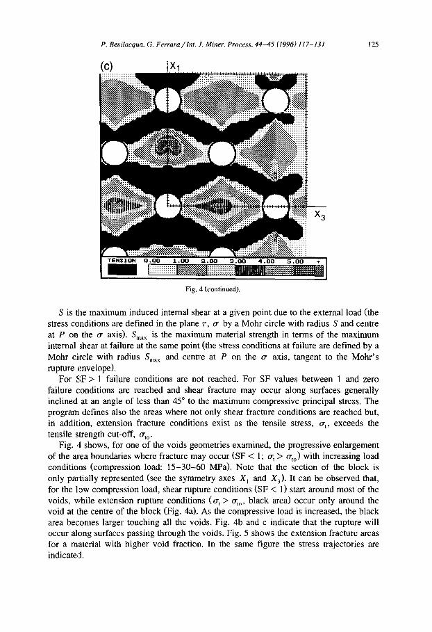
Fig. 4 (continued).
S is the maximum induced internal shear at a given point due to the external load (the stress conditions are defined in the plane T, (T by a Mohr circle with radius S and centre at P on the (+ axis). S,,,,, is the maximum material strength in terms of the maximum internal #shear at failure at the same point (the stress conditions at failure are defined by a Mohr circle with radius S,,,,, and centre at P on the (T axis, tangent to the Mohr’s rupture envelope).
For SF > 1 failure conditions are not reached. For SF values between 1 and zero failure conditions are reached and shear fracture may occur along surfaces generally inclined at an angle of less than 45” to the maximum compressive principal stress. The program defines also the areas where not only shear fracture conditions are reached but, in addition, extension fracture conditions exist as the tensile stress, CT~, exceeds the tensile strength cut-off, fltO.
Fig. 4 shows, for one of the voids geometries examined, the progressive enlargement of the area boundaries where fracture may occur (SF < 1; q > c~,,) with increasing load conditions (compression load: 15-30-60 MPa). Note that the section of the block is only partially represented (see the symmetry axes X, and X,). It can be observed that, for the low compression load, shear rupture conditions (SF < 1) start around most of the voids, while extension rupture conditions (q > crtO, black area) occur only around the void at the centre of the block (Fig. 4a). As the compressive load is increased, the black area becomes larger touching all the voids. Fig. 4b and c indicate that the rupture will occur along surfaces passing through the voids. Fig. 5 shows the extension fracture areas for a material with higher void fraction. In the same figure the stress trajectories are indicated.
126 P. Bevilacqua, G. Ferrara /ht. J. Miner. Process. 44-45 (I 996) I IT- 13 1
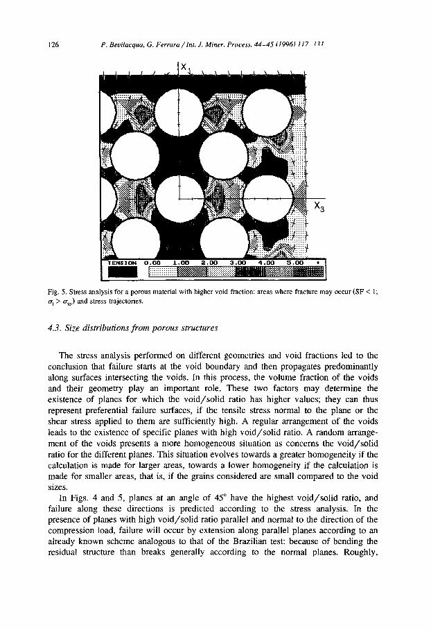
Fig. 5. Stress analysis for a porous material with higher void fraction: areas where fracture may occur (SF < 1; a, > a,,) and stress trajectories.
4.3. Size distributions from porous structures
The stress analysis performed on different geometries and void fractions led to the conclusion that failure starts at the void boundary and then propagates predominantly along surfaces intersecting the voids. In this process, the volume fraction of the voids and their geometry play an important role. These two factors may determine the existence of planes for which the void/solid ratio has higher values; they can thus represent preferential failure surfaces, if the tensile stress normal to the plane or the shear stress applied to them are sufficiently high. A regular arrangement of the voids leads to the existence of specific planes with high void/solid ratio. A random arrange- ment of the voids presents a more homogeneous situation as concerns the void/solid ratio for the different planes. This situation evolves towards a greater homogeneity if the calculation is made for larger areas, towards a lower homogeneity if the calculation is made for smaller areas, that is, if the grains considered are small compared to the void sizes.
In Figs. 4 and 5, planes at an angle of 45” have the highest void/solid ratio, and failure along these directions is predicted according to the stress analysis. In the presence of planes with high void/solid ratio parallel and normal to the direction of the compression load, failure will occur by extension along parallel planes according to an already known scheme analogous to that of the Brazilian test: because of bending the residual structure than breaks generally according to the normal planes. Roughly,
P. Bevilacqua, G. Ferrara/Int. J. Miner. Process. 44-45 (1996) 117-131 127
10
% Passing
1
1 10
Particle Size (mm)
100
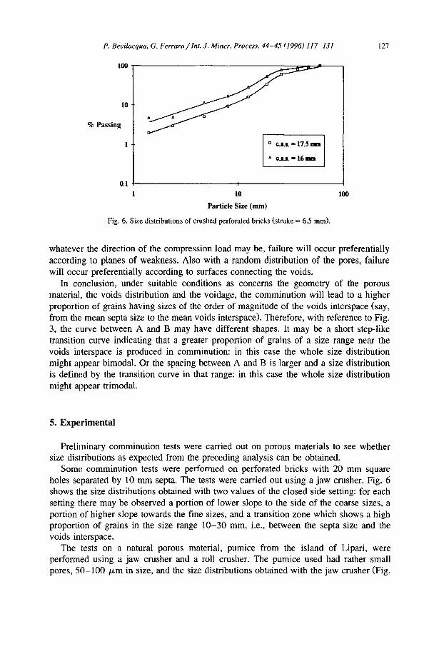
Fig. 6. Size distributions of crushed perforated bricks (stroke = 6.5 mm).
whatever the direction of the compression load may be, failure will occur preferentially according to planes of weakness. Also with a random distribution of the pores, failure will occur preferentially according to surfaces connecting the voids.
In conclusion, under suitable conditions as concerns the geometry of the porous material, the voids distribution and the voidage, the comminution will lead to a higher proportion of grains having sizes of the order of magnitude of the voids interspace (say, from the mean septa size to the mean voids interspace). Therefore, with reference to Fig. 3, the curve between A and B may have different shapes. It may be a short step-like transition curve indicating that a greater proportion of grains of a size range near the voids interspace is produced in comminution: in this case the whole size distribution might appear bimodal. Or the spacing between A and B is larger and a size distribution is defined by the transition curve in that range: in this case the whole size distribution might appear trimodal.
5. Experimental
Preliminary comminution tests were carried out on porous materials to see whether size distributions as expected from the preceding analysis can be obtained.
Some comminution tests were performed on perforated bricks with 20 mm square holes separated by 10 mm septa. The tests were carried out using a jaw crusher. Fig. 6 shows the size distributions obtained with two values of the closed side setting: for each setting there may be observed a portion of lower slope to the side of the coarse sizes, a portion of higher slope towards the fine sizes, and a transition zone which shows a high proportion of grains in the size range lo-30 mm, i.e., between the septa size and the voids interspace.
The tests on a natural porous material, pumice from the island of Lipari, were performed using a jaw crusher and a roll crusher. The pumice used had rather small pores, 50-100 pm in size, and the size distributions obtained with the jaw crusher (Fig.
128 P. Beuilacqua, G. Ferrara / Int. J. Miner. Process. 44-45 (1996) 117-131
100
KPrriy 10
1
4 c.l.r.=3m
?? c.s.r.-5nm
x C.S.,. = 6.5 -
10 100 loo0 10000
Paicksize(microa)
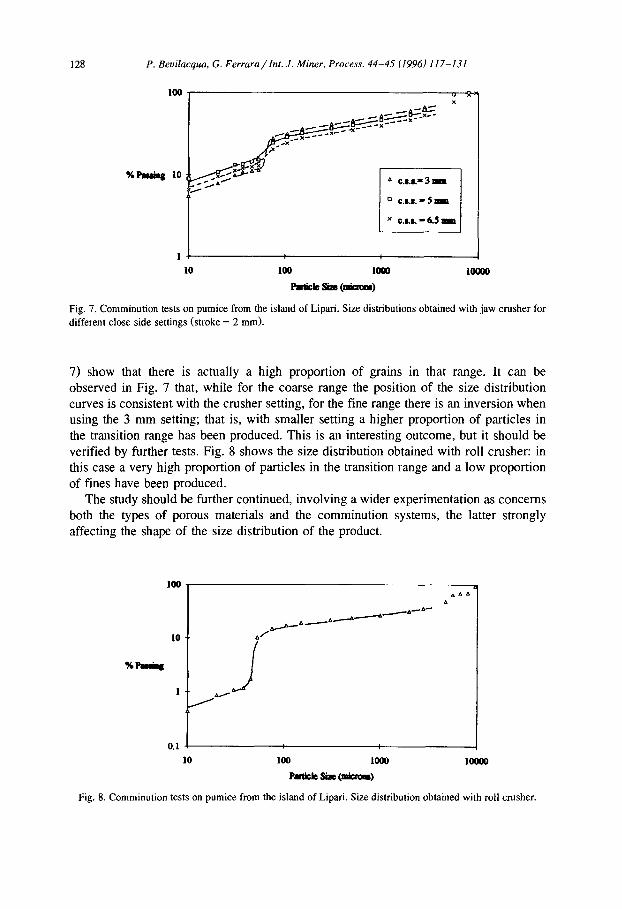
Fig. 7. Comminution tests on pumice from the island of Lipari. Size distributions obtained with jaw crusher for different close side settings (stroke = 2 mm).
7) show that there is actually a high proportion of grains in that range. It can be observed in Fig. 7 that, while for the coarse range the position of the size distribution curves is consistent with the crusher setting, for the fine range there is an inversion when using the 3 mm setting; that is, with smaller setting a higher proportion of particles in the transition range has been produced. This is an interesting outcome, but it should be verified by further tests. Fig. 8 shows the size distribution obtained with roll crusher: in this case a very high proportion of particles in the transition range and a low proportion of fines have been produced.
The study should be further continued, involving a wider experimentation as concerns both the types of porous materials and the comminution systems, the latter strongly affecting the shape of the size distribution of the product.
0.1 4 10 100 1000 1OtIOO
Pakksizc(miaom)
Fig. 8. Comminution tests on pumice from the island of Lipari. Size distribution obtained with roll crusher.
P. Bevilucqua, G. Ferraru/Int. J. Miner. Process. 44-45 (1996) 117-131 129
6. Conclusions
(1) The mechanical behaviour of porous materials differs from that of non-porous materials. It varies considerably according to the volume fraction of voids, the type of porosity, the shape and the degree of interconnection of the voids.
(2) For porous materials, a different behaviour can be expected for the two comminu- tion ranges above and below the mean voids interspace. In fact, for the coarse particles (say, from 5-10 times the voids interspace up to the top size of the feed) the mechanical behaviour of the material is related to the porous material defined by its bulk mechanical properties. In contrast, below the mean voids interspace down to very fine sizes the mechanical behaviour of the material is related to the non-porous material constituting the matrix. Therefore, a transitional region between the coarse region and the fine region should exist (near the mean voids interspace), so that the size distributions are bi- or trimodal.
(3) The transitional region is related to the comminution of particles characterized by voids fairly large in size with respect to the particles. The analysis of the stresses existing in this type of porous structures subjected to compression load showed that failure occurs preferentially according to surfaces passing through the voids. Therefore, a high proportion of grains close in size to the mean voids interspace will be produced in many cases; this fact characterizes the transition zone of the size distribution.
(4) The indications given in the preceding points were verified, through comminution with jaw crusher and roll crusher, on perforated bricks and natural pumice. However, the results are strongly dependent on the material and the type of porosity, so that different results may be expected for materials differing from the models of porous materials considered. It is therefore desirable that the experimental research should be further continued by investigating different materials and comminution systems.
Acknowledgements
The authors wish to thank the company Pumex S.p.A., Lipari, for the collaboration given and the Ministry of the University and Scientific Research for the financial support. Thanks also to E. Castelli for the help in the stress analysis and to A. Girometta for carrying out the experiments.
References
Amould, M. and Virlogeux, M., 1986. Le beton 1Cger. Presses de 1’Ecole Nationale des Ponts et Chat&es, Paris.
Budiansky, B. and O’Connel, R.J., 1976. Elastic moduli of a cracked solid. Int. J. Solids Struct., 12: 81-97. Carey, W.F. and Bosanquet, C.H., 1933. A study of crushing brittle solid. J. Sot. Glass Technol., 17:
384-410. Clark, I.H., 1992. Microstructural control on crushing strength and mineral liberation potential: numerical
experiments. In: SK. Kawatra (Editor), Comminution - Theory and Practice. SME-AIME, Ch. 7, pp. 85-95
130 P. Beuilacqua, G. Ferrara/Int. J. Miner. Process. 44-45 (1996) 117-131
Clark, I.H., 1993. The role of rock fabric in controlling crushing strength: numerical experiments. In: Proc., XVIII Int. Mineral Processing Congress, Sydney, Vol. 1, pp. 187- 192.
Curran, J.H. and Corkum, T.B., 1988-91. Examine 2D-Version 3.1. DVL - Data Visualization Laboratory, University of Toronto.
Dunn, D.E., LaFountain, L.J. and Jackson, R.E., 1973. Porosity dependence and mechanism of brittle fracture in sandstones. J. Geophys. Res., 78(14): 2403-2417.
Fatt, J. and Davis, D.H., 1912. Reduction in permeability with overbunden pressure. Trans. AIME: 329. Ferrara, G., Bevilacqua, P. and Meloy, T.P., 1993. Liberation of voids by comminution - its influence of
apparent density of porous materials. Powder Technol., 76: 89-94. Friedman, M., 1976. Porosity, permeability and rock mechanics - a review. In: W.S. Brawn, S.J. Green and
W.A. Hustrulid (Editors), Site Characterization. Proc., 17th US Symposium on Rock Mechanics, Snow- bird, UT, p. 2 Al-1-17.
Gaudin, A.M. and Yavasca, S.S., 1946. Principles of comminution - size and surface distribution. Trans. AIME, 169: 88-94.
Gaudon, P. and Struillou, R., 1976. Etude theorique en laboratoire du couple densit&r&istance mkanique des granulats 16gers mintraux artificiels. Ministtre de I’lndustrie et de I’Equipement, 16 pp., Annexes I a IV, Association pour la recherche et le developpement des methodes et processus industriels, Annines, Paris.
Gildemeister, H.H. and Schiinert, K., 1976. Bruchphlnomene und Spannungsfeld in prallbeanspruchten Kugehr. Dechema-Monographien, Band 79. Dechema Frankfurt, VerIag Chemie, Weinheim, pp. 13 1- 149.
Hoshino, K., 1974. Effect of porosity on the strength of the elastic sedimentary rocks. In: Proc., 3rd Int. Congr. Rock Mechanics, Denver, CO, Vol. IIA, Advances in Rock Mechanics, pp. 511-516.
Kowalski, WC., 1966. The interdependence between the strength and voids ratio of limestones and marls in connection with their water saturating and anisotropy. In: Proc., 1st Int. Congr. Rock Mechanics, Lisbon, Vol. 1, pp. 143-144.
Lightweight Aggregate Concrete - CEB-FIP Manual. The Construction Press, 1977. Matheron, G., 1972. Les polyedres poissonniens isotropes. In: Proc. 3rd European Symp. Comminution,
Cannes, Dechema Monographien Nr. 1292-1326, Band 69, pp. 575-600. Miles, R.E., 1969. Poisson flats in Euclidean space - Part 1. Adv. Appl. Prob., 1: 21 l-237. Nash, K.L., 1953. The shearing resistance of fine closelygraded sand. In: Proc., 3rd Int. Conf. on Soil
Mechanics and Foundation Engineering, Vol. 1, pp, 160- 164. Prasher, C.L., 1987. Crushing and Grinding Process Handbook. Wiley, New York. Price, N.J., 1960. The compressive strength of coal measure rocks. Colliery Eng.: 283-292. Price, R.H., 1983. Analysis of rock mechanics properties of volcanic tuff units from Yucca Mountain, Nevada
test site. Sandia National Laboratories Report SAND 82-13 15. Price, R.H. and Bauer, S.J., 1985. Analysis of the elastic and strength properties of Yucca Mountain tuff,
Nevada. In: Proc., 26th US Symposium on Rock Mechanics, Rapid City. Balkema, pp. 89-96. Rumpf, H., Faulhaber, F., Schijnert, K. and Umhauer, H., 1967. Analyse der Brucherscheinungen in
Glaskugeln und kreisrunden Glasscheiben. Dechema-Monographien Nr. 994 1026, Band 57, Dechema Frankfurt, Verlag Chemie, Weinheim, pp. 85- 126.
Rumpf, H. and Schiinert, K., 1972. Die Bruchetscheinungen in Kugem bei elastischen sowie plastischen Verfonnungen durch Druckbeanspruchung. Dechema-Monographien Nr. 1292-1326, Band 69, Dechema Frankfurt, Verlag Chemie, Weinheim, pp. 5 l-80.
Schijnert, K., 1973. Single particle crushing of polymers. In: H. Heywood Memor. Symp., Loughborough University of Technology.
Schonert, K., 1979. Aspects of the physics of breakage relevant to comminution. In: Proc., 4th Tewksbury Symp. Fracture, University of Melbourne, pp. 3: l-3:30.
Seeburger, D.A. and Nur, A., 1984. A pore space model for rock permeability and bulk modulus. J. Geophys. Res., 89: 527-536.
Shinohara, K., 1984. Fundamental Properties of powders - Part 1: Rheological properties of particulate solids. In: M.E. Fayed and L. Olten (Editors), Handbook of Powder Science and Technology. Van Nostrand Reinhold Co., New York, Ch. 5, pp. 129-169.
Skempton, A.W., 1948. A study of the immediate triaxial test on coesive soils. In: Proc., 2nd Int. Conf. on Soil Mechanics and Foundation Engineering, Rotterdam, Vol. 1, pp. 192- 196.
P. Bevilacqua, G. Ferrara /ht. J. Miner. Process. 44-45 (1996) 117-131 131
Smekel, A., 1938. Compression comminution of cubic single particles. Z. VDI Beih. Verfahrenstech., 6: 159-165.
Toksoz, M.N., Cheng, C.H. and Timur, A., 1976. Velocities of seismic waves in porous rocks. Geophysics, 41: 621-645.
Zimmerman, R.W., 1984. Elastic moduli of a solid with spherical pores: new self-consistent method. Int. J. Rock Mech. Min. Sci. Geomech., 21: 339-343.
Zimmerman, R.W. and King, MS., 1985. Propagation of acoustic waves through cracked rocks. In: Proc., 26th US Symposium on Rock Mechanics, Rapid City. Balkema, pp. 739-745.