commissioning plan of bepcii storage rings j.q. wang april 26, 2006
TRANSCRIPT

Commissioning Plan of BEPCII Storage Rings
J.Q. WangApril 26, 2006

Outlines1. Commissioning of devices and control
system
2. Commissioning of Backup Scheme without SCQ and detector
3. Commissioning of BEPCII with SCQ
4. Commissioning of BEPCII with detector
5. Luminosity increase strategy
6. Commissioning of SR mode with SCB

1. Commissioning of devices and control system--Preparation for beam commissioning
May to Sept, 20061.1 Central control system installation and test
1.2 Devices and Local control system installation & debug
1.3 Integral system debug off-line
1.4 Integral system debug on-line
1.5 Set up operation manual and Training the operators
1.6 Final check for starting beam commissioning

1.1 Central control system installation and test
From May to July 2006 Network system configuration and test SUN V880 server & cluster configuration and test EPICS system and development environment installation
and test EPICS Base and Extensions SAD development environment CVS,NFS system and third party software
PC/Linux EPICS system and application installation and test
Above computers are located in Central Control Room (CCR)

1.2 Devices and Local control system installation & debug (From May to July 2006)
All of local control system installation and integration with devices and the systems start up at local PCs
Including Vacuum control system PS control system Cryogenic control system RF control system Interlock system
Tasks - installation,wiring test, individual device test , calibration, system integration of hardware and software
Timing system of storage ring will develop continually and it will be done by the end of August
Console OPI and wall display test in CCR

1.3 Integral system debug off-line
From 20th of July to the end of August Integration of central control system and local con
trol system Start up control system on console in CCR Access local IOCs on console in CCR Control function debug and test Application software test Data Archiving test Alarm handler test Access safety control test Wall display test

1.4 Integral system debug on-line
In September Debug and test control system with real equipment on cons
ole in CCR Start up whole system at console Control/monitor subsystem device including PS, VA, RF, BI,
Timing and linac devices Control function test Final parameter calibrations Interlock system debug with device After test, fix all of software and hardware, including save p
rograms, configuration parameters, IOC database…, and make backup version.

Content for Device & Control debug on-line
Transport line: Magnet and power supply: check the polarity
and strength of magnet with power supply, do standardization, 8 hours stability check, central control operation, power supply safety interlock check,
Beam instrumentation: Beam profile monitor operation from CCR, communication between IOC of BPM and central console
Content for Device & Control debug on-line
storage ring: Magnet and power supply: from May, after installation
of one quarter is finished, the vacuum and power supply with be tested with local control system.
For power supply and magnet: the polarity and strength should be checked, Standardization, long term stability, water cooling system, temperature monitor system.
RF: Display and adjust the voltage, frequency, phase in CCR
Vacuum: Control of valve from CCR, display vacuum status, temperature monitors of vacuum chamber
Beam instrumentation: IOC(BPM) with console, DCCT, BCM, PR

Inspection sheets for device check before power on and commissioning procedures of magnets, power supply with
control system (Co-signed by group leaders)

Check-out list of Storage ring before power on
Subsystem Content to be checked Result Signature
Mechanic
1)Position of the half unit
1)Cleaning, no iron pieces left
1)Supporting board removed, chamber support right
Magnet
1)B、 Q、 S、 correctors and shunt on Bs are connected with right polarity
1)Up and down current leads connected
1)B、 Q、 S cooling water connected, the pressure of water flow, no leakage
Vacuum
1)No abnormal on vacuum pump, photon absorber
1)Cable to pump, vacuum gauge connect correctly
1)RF shielding spring installed in right positron, the bellows in normal length
1)Cooling water channel of photo absorber, vacuum chamber and bellows connected with proper pressure, no leakage

Subsystem Content to be checked Result Signature
Powersupply
1) Check the polarity and connection of cable to B、Q、 S、 correctors
2) Current leads isolated from other conductors
3) Temperature monitors on B、 Q、 S coils installed
4) Polarity and connection of the auxiliary coil on B
5) The girder and magnets well grounded
7) Cable for temperature monitors of B、 Q、 S are connected properly
ControlCable of temperature monitors on vacuum chamber
properly connected
Beam Inst.
Cable to BPMs
PhysicsSolenoid on positron rings wined and connect
between each other
Check-out list (cont’d)

Subsystem Content to be checked Result Signature
Power Supply
1.Fill the Check list before power on; Check jointly with magnet group the cooling water, PS connection OK, the cooling water supply OK. A warning board raised.
1.Temperature protection system of magnets works normally, check all the thermal coupler, the channel right, the cooling water system of power cabinet, Switch on
1.Close the main circuit with small current to check each part of the power supply works OK, check the correlation between PS and magnet.
magnetphysics
1)The load connects properly, with low current (<50A) to check the polarity of the magnet. Power the B, Q, S with 100A, Power the steering magnet with 50% of designed current, to check the voltage on the magnet OK or not.
Power supply
1)Local control of PS, ripple and stability adjustment
1)Take randomly 2 points of each set of( B、 Q、 S) to check the temperature interlock with simulated over heating signal at the thermal detecting point
Commissioning Procedure of magnet, power supply and control system

Subsystem Content to be checked Result Signature
ControlPS
1)Check remote control of PS, Correlation between PSI and PS, switch on & off, lift & down current, read back data reliable.
PSmagnet
1)Check of water flow in magnet, power supply; interlock system for magnet temperature alarm, With cooling water on, magnet powered with 80% of designed value for 1-2 hours:Check the voltage on the magnet and recordWith hands or thermometer to check the heating up status of the coils of magnets.Measure the temperature of the power component Check the channel for temperature interlock system of magnets
PSControl
1)With remote control, to check the stability of power supply, the interlock system of temperature, the fast patrol inspection system:Q、 S powered with 120A for 12h;B powered with 20%IR/8h, 50%IR/24h, 90%IR/8h;Steering magnet: 50%IR/8h;
1)Measure and get the curve for output of PS and the designed value, respectively, and put into database
PSMagnet
1) Operation with temperature interlock, with 90% of designed current for 48 hours training. Check the temperature.
Commissioning Procedure (cont’d)
Engineer : Head of Storage ring : Chief engineer : Date:
1.5 Set up operation manual and Training the operators
In September Set up operation manual for each
subsystem (local and central control) Introduction to the beam optics for
operation and the procedure of commissioning
Set up safety control rules for personal and devices, particularly, the interlock radiation protection system.

1.6 Final check for starting beam commissioning
Oct. 5 to 9, 2006 The polarity of each magnet consists with
the setting from control system All the vacuum valves open, all the PRM up The temperature monitor systems for
vacuum chamber and the power supply cables are OK.
Safety interlock system responses properly.

2 Schedule of Beam Commissioning
2006/10/10-2007/02/23 commissioning of backup scheme
2007/02/24-2007/03/31 move SCQ into the IR
2007/03/11-2007/08/24 commissioning without detector
2007/08/25-2007/09/18 move BESIII detector into the IR
2007/09/19-2007/10/14 commissioning with detector
2007/10/15- HEP operation with detector
2008/10/15 31032cm-1s-2

2.1 Backup scheme without SCQ
Due to the delay of SC components in IR, a backup scheme to use two normal conducting dipoles instead of SC magnets package will be adopted, the main purpose: to start the beam commissioning of the
BEPCII rings in the last quarter of this year. and if available, to provide beam to SR users
to commission both the electron and positron ring to check the parts with room temperature magnets are OK.

Beam orbit in IR with two 70B dipoles Backup Scheme

Commissioning schedule of Backup Scheme
2006/10/10-2006/11/08 30 commissioning for SR mode
2006/11/09-2006/12/28 50 commissioning beam lines and SR operation
2006/12/29-2007/01/25 28 commissioning e ring
2007/01/26-2007/02/22 28 commissioning e ring

2.2 Commissioning for SR mode2.2.1 Transport line to Ring (3 days) Check the e- transport line is OK: energy, orbit From linac exit, one by one, get the beam signal from PR & B
PM, till the last Adjust the orbit to make the best BCT transport efficiency Energy spread from Linac check and optimized with movabl
e masks on the transport line Get the signal on PR near the injection point Set the right strength of lamberston magnet Get the beam signal on the first BPM in the ring with oscillos
cope

Beam signal from upstream BPM as trigger Beam signal
from downstream BPM

2.2.2 First turn of electron (no RF) and Accumulation (with RF) (3-7 days)
Similar to transport line, one by one adjust the orbit along the ring with BPM
Tune the timing of kicker is OK with BPM in the R4 region
With beam signal be observed on all BPMs on the ring, adjust the kicker strength to get 100s turns
Adjust RF voltage to get more turns, till accumulation

2.2.3 Commissioning Instrumentation and control system with beam (2 weeks)
Beam accumulated up to 5mA, available for BPM works properly,
Commission the diagnostics with beam: BPM system, tune measurement system, SRM system
Commission the control system with beam: Debug with hardware (PS, TM, RF) Debug application software: set Optics, fit optics
Tune RF freq. ; Do COD correction Measure the beta functions to check the optics Response matrix measurement Beta function correction and optics optimization

2.2.4 Commissioning the SR mode (10 days)
RF voltage increase to 1.2MV, Single bunch current of 5mA, ramping energy from
1.89GeV to 2.5GeV, set wigglers COD correction for SR mode @2.5 GeV Commissioning of Multi-bunch injection, BCM syst
em Increase the beam current up to 100mA according
to vacuum condition, Increase beam current further for instability obser
vation with SRM, spectra analyzer, and tune the feedback system

2.3 Commissioning the beam line and SR Operation
Nov. 9 to Dec. 28 Local bump adjust for SR beamlines (20 days) Provide beam to SR users (30 days), I=100mA,
beam lifetime: 10 hoursIf the radiation safety allowed, Meantime to com
mission the positron transport line.

2.4 Commissioning for e- ring without SCQ Dec 29,2006 – Jan. 25, 2007
(Can be shorten or canceled if SCQ ready in early )
Purpose: to check the inner half of e- ring without SCQ.
Injection into the e- ring and store beam up 5mA,
Commission the BPM in the inner half ring, do COD correction
Measure the tune, beta function to check the lattice is OK (the Q magnets)

2.5 Commissioning for e+ ring without SCQDec 29,2006 – Jan. 25, 2007(Can be shorten or canceled if SCQ ready in early) Purpose: to check the inner half of e+ ring witho
ut SCQ Commissioning transport line of e+: trace the be
am signal of BPM (or PR, PMT) one by one till to the ring injection point,
Measure the the energy spread and emittance of the beam with adjustable slot and BCT, then optimize them with linac

2.5 Commissioning for e+ ring without SCQ (cont’d)
Similar to the first turn of electron injection, adjust the orbit, the timing and strength of kicker to store beam. Due to the weak beam, profile monitor (or PMT) as the supplement to BPM, may be used to commission the first turn of positron beam.
With 5mA beam, commission the BPM in the inner half ring, do COD correction.
Measure the tune, beta function to check the lattice is OK (the Q magnets)

3 Commissioning BEPCII with SCQ but without detector
2007/02/23-2007/03/31 37 move SCQ into the IR2007/04/01-2007/04/20 20 commissioning e ring2007/04/21-2007/05/10 20 commissioning e ring2007/05/11-2007/06/09 30 commissioning for collisi
on mode2007/06/10-2007/08/23 75 commissioning for colli.
mode with large current

3.1 Commissioning e- ring with SCQ
2007/04/01-2007/04/20 For easy injection and accumulation, an injection mod
e (betay@IP=2 cm; x/y=6.6/5.6, easy tuning with large DA)
With 5mA bunch, measure the orbit, Tune the RF freq., COD correction, measure the tune, the beta functions,
Response matrix measurement, correct beta functions, Multi-bunch injection Tuning the lattice to collision mode betay@IP=1.5 cm;
x/y=6.53/5.58

3.2 Commissioning e+ ring with SCQ2007/04/21-2007/05/10 Procedure Similar to e- ring
commissioning, while PR and PMT will be used for first turn injection and accumulation.

3.3 Commissioning the Collision without detector
2007/05/11-2007/06/09 Commissioning of application software and beam
diagnostics for IR tuning Tuning collision
Longitudinal: RF phase scan to observe the time signals from 8-pole BPM near the IP to get the right IP.
Horizontal beam-beam scan, and IR orbit correction with 4-bump,
Vertical beam-beam scan and orbit bump Coupling measurement and correction with skew q
uard.

3.4 Improvement on Beam current and Luminosity2007/06/10-2007/08/23
Optics optimization on beta functions at IP, coupling correction, orbit adjustment at IP
Tuning the movable mask for lower background
Tuning kicker for top-off injection Beam current increase with multi-bunch, up to
300mA, beam instability observation (including ECI) and tuning the feedback system,
Goal: Luminosity up to 5-101031cm-2s-1 with sufficient low background

4 Colliding with detector
(2007/08/25-2007/09/18 BESIII rolled in)
2007/09/19-2007/10/18, after BESIII rolled in Coupling compensation with anti-solenoid
and skew quad IR tuning with detector Control background Goal: Luminosity recovered to 5-101031cm-
2s-1
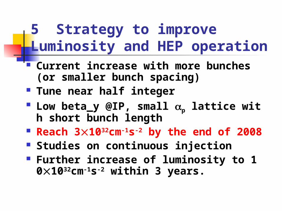
5 Strategy to improve Luminosity and HEP operation
Current increase with more bunches (or smaller bunch spacing)
Tune near half integer Low beta_y @IP, small p lattice with sho
rt bunch length Reach 31032cm-1s-2 by the end of 2008 Studies on continuous injection Further increase of luminosity to 101032
cm-1s-2 within 3 years.

6 Commission the SR mode with SCB and SR operation
In the year of 2007 and 2008, we will provide beam time to SR users.
The SR mode with SCB will be commissioned, as well as the beamlines

Remarks The estimation of time period for the
beam commissioning schedule refers to experience of KEKB and PEPII.
During the commissioning period, it’s inevitable some fault or mistakes of hardware system, so the schedule should be adjusted accordingly
Several task forces formed for commissioning the critical systems: cryogenic, SCQ, SC RF

Acknowledgement
Prof. Jijiu Zhao prepared the plan of control system
Prof. Nan Huang prepared the draft of the commissioning schedule

Thank you !


1998 May Commission fully upgraded linac and transport lines1998 Nov. 30 KEKB installation complete1998 Dec. 13 HER beam first stored1999 Jan. 14 LER beam first stored1999 Jan. 26 First beam-beam collisions1999 March 26 Luminosity of 1.2x10**311999 May BELLE installed2000.04 1.0*10^332000.07 2.0*10^33
Commissioning of KEKB

Commissioning of PEPII 1997 June HER installation complete 1997 June 16 HER beam first stored 1997 June e+ injection transport studies 1998 January LER injection (part turn) 1998 July 10 LER construction complete 1998 July 16 LER beam first stored 1998 July 23 First collisions 1998 Dec. 8 8 x10**31 luminosity 1998 Feb. 8 5.2 x 10**32 luminosity 1999 May BABAR detector installed 1999 Aug. 8 x 10**32 luminosity