commissioning requirements for trajectory, orbit and tune measurements t. lefevre on the behalf of...
TRANSCRIPT

Commissioning requirements for Trajectory, Orbit and Tune measurements
T. Lefevre on the behalf of the BI teams involved
LBOC 9 September 2014

9 September 2014 2
Scope• Only Measurements and not Feedbacks
• Requirements for commissioning time with beam and for the ramp-up in intensity (including scrubbing)
• A list of the modifications/improvements occurred during LS1 if not presented yet and a break-down of the activities and preparation required for:• operation with pilot bunches• operation with single nominal bunches• operation with trains
T. Lefevre – LBOC
3
BPM after LS1
• 2 BPMs installed in point 4, few BPMs repaired or modified
• New thermalized racks with corresponding alarms
• New CPU MEN A20 in VME crate and Firmware modifications and porting to FESA 3
• Software modifications • New algorithm for BPM non-linearity corrections
T. Lefevre – LBOC 9 September 2014

4
BPM commissioning plans
T. Lefevre – LBOC 9 September 2014
• Assume that the stability of thermalized rack has been assessed
• Assume that FW and SW checks has been intensively done during cold check-out• Calibration, logging process, Post-Mortem
buffers can be tested earlier without beam
• Assume that FIFO mode is operational during Injection tests

5
BPM commissioning plans
T. Lefevre – LBOC 9 September 2014
• List of beam tests using Pilot bunch• Connectivity tests using kick response and with RF
trimming (6h)• To find possible polarity inversion• To find faulty channels with large errors
• BPM phasing to verify the capture and bunch orbit mode (IQC)
• Qualification of the new BPM non-linear corrections:• Correction depends on the BPM geometry: 7 to be
tested with orbit bumps (8h)
• Commissioning of the Interlock BPM • Check position threshold for BPMINT (2h)

6
BPM commissioning plans
T. Lefevre – LBOC 9 September 2014
• List of beam tests using Nominal bunch• Commissioning of the LHCBPMIT. Bumps and slow
bunch cleaning with ADT• to check intensity ranges with scraping (4h)
• List of beam tests using Trains• Test the automatic filter setup
• Optimize the resolution of the Orbit data (2h)
• Test Synchronous Orbit mode (4h)• To provide better resolution for IR BPMs
• Validation of interlock BPM with Doublet beams• To check position threshold (2h)
7
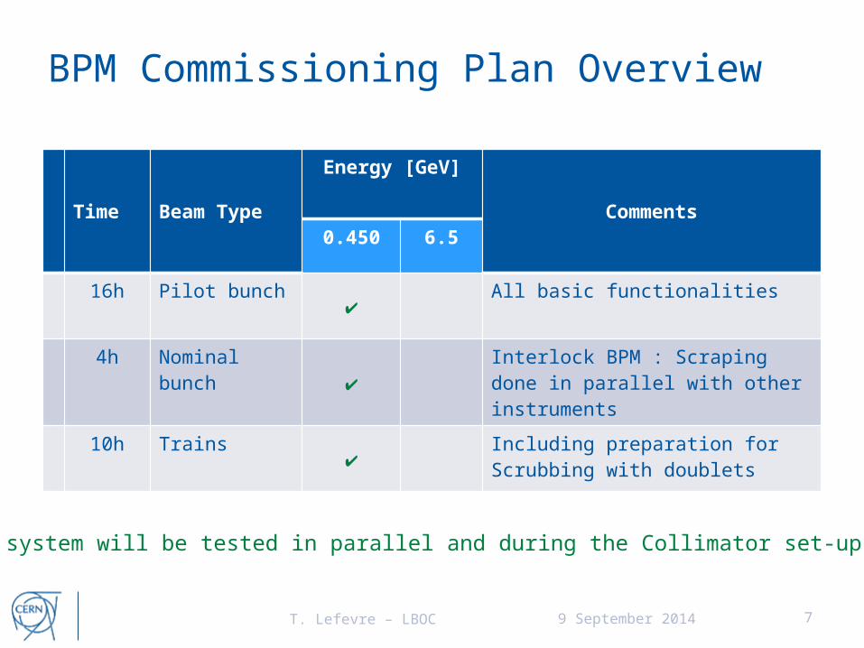
BPM Commissioning Plan Overview
Time Beam Type
Energy [GeV]
Comments0.450 6.5
16h Pilot bunch✔
All basic functionalities
4h Nominal bunch✔
Interlock BPM : Scraping done in parallel with other instruments
10h Trains✔
Including preparation for Scrubbing with doublets
T. Lefevre – LBOC 9 September 2014
DOROS system will be tested in parallel and during the Collimator set-up time

8
TUNE after LS1• Hardware modifications
• 2 Add. Pick-ups but no add. Digital acquistion• FFT1, FFT2, FFT3 and ‘on-demand’ systems as before
• Some Software – Firmware modifications• Mainly for the implementation of the BTF
• New Gated Excitation scheme using ADT • New functionality of the damper to chirp on a
selected bunch: to be implemented in software
T. Lefevre – LBOC 9 September 2014

9
Tune commissioning plans
T. Lefevre – LBOC 9 September 2014
• List of beam tests using Pilot bunch• Re-commissioning of Tune, Coupling and Chromaticity
measurements (4h)
• List of beam tests using Nominal bunch• Re-commissioning of Tune, Coupling and Chromaticity
diagnostic (8h)• Investigate of the interplay between the BBQ and the ADT (0.45
and 6.5 TeV)
• List of beam tests using Trains• Gated Tune monitor and Gated excitation (8h)

10
Tune commissioning Plan Overview
Time Beam Type
Energy [GeV]
Comments0.450 6.5
4h Pilot bunch ✔ ✔
Check Tune, Coupling, Chroma, Chirp
8h Nominal bunch ✔ ✔
Understand interplay between damper and tune
8h Trains✔ ✔
Gated control for Gated tune Gated excitation with Damper
T. Lefevre – LBOC 9 September 2014
Schottky measurements will be investigated in parallel

11
Beam Presence Flag Commissioning Plan Overview
Time Beam Type
Energy [GeV]
Comments0.450 6.5
2h Pilot ✔ X Scraping with pilot
T. Lefevre – LBOC 9 September 2014

12
Thank you
T. Lefevre – LBOC 9 September 2014

I could be brief…
BPM – Standard WBTNo The WBTN resolution in Orbit mode measured ~few μm
o Suffered from long-term drift in position due to temperature variation in VME integrator mezzanine
o Installation of Water cooled racks (48) completed by the end of April (10 months of installation)
VME based Digital Acquisition Board and WBTN Mezzanine Cards
12:00 13:00 14:00 15:00 16:00 17:00-1020
-1010
-1000
-990
-980
-970
-960
Local Time (2010-04-12)
H P
ositio
n o
n B
PM
SW
.1R
8 (
um
)
12:00 13:00 14:00 15:00 16:00 17:0027.5
28
28.5
29
Local Time (2010-04-12)
Cra
te t
em
pera
ture
(deg.
C)
from 2010

I could be brief…
BPM – Water cooled racksThermalized Racks (BPM & BLM) consist of: o A temperature controller module that regulates the cool water flow depending on
the cabinet temperature and monitors the status of the alarms. o 3 Alarms (per IP) have been implemented will be sent to TIM at the CCC :
o Inlet water temperature, status of Rack fan , Cabinet temperatureo if the last alarm (T° inside the cabinet) exceeds a safety level, the rack doors will
open automaticallyo Alarms consist in NC (normally closed) switches connected via daisy chaino No direct connection to BIS foreseen for the moment !
PID Temp. Ctr.
Flow control
CabinetT°
WaterT°
Fan monitoring
BPM crate
BPM crate
Rack 2Rack 1 Rack 4Rack 3
Towards SYG alarm system rack
Today, only SR1 and SR6 have the water circuits “in service”. Currently studying the cabinet temperature stability. Water flow and PID tuning optimization is being assessedFan alarm
Water T° alarm
Cabinet T° alarm24V
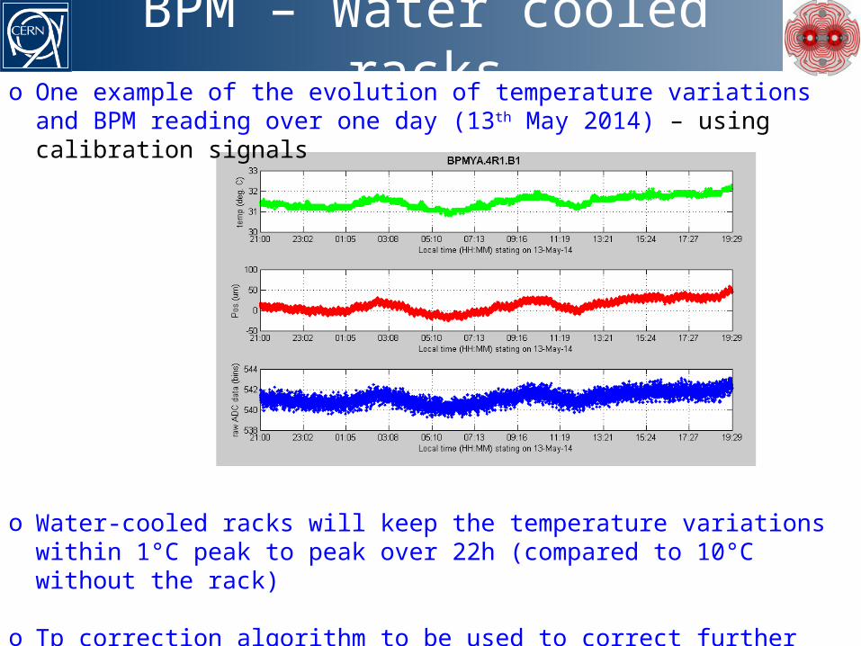
BPM – Water cooled rackso One example of the evolution of temperature variations and BPM reading over one
day (13th May 2014) – using calibration signals
o Water-cooled racks will keep the temperature variations within 1°C peak to peak over 22h (compared to 10°C without the rack)
o Tp correction algorithm to be used to correct further the observed drifto RMS noise measured to be between 2-5um depending on the channels
(possibly hitting the stability of our calibration source)

BPM with DOROSo DOROS developed to process BPM signals with <um resolution
o It is optimised foro position resolution, absolute accuracy of centred beam, robustness and simplicity
o It assumes: o bunch-by-bunch is not needed, required bandwidth is in the Hz rangeo larger beam offsets (> 1 mm) not measured with high precision (< 1 µm)
o Prototyped for Collimators BPMs, Demonstrated sub-micrometre resolution at SPS and LHC
operational H.B1operational H.B2
DOR H.B1DOR H.B2
0 30 60 90 120 150 180
Measurement time [s]
-80
-60
-40
-20
0
20
40
60
Bea
m p
osit
ion
chan
ge
[µm
]
Operational vs. Diode ORbitLHC fill #3316 (23/11/12)
BPMSW.1L5.B1+B2aperture 61 mm
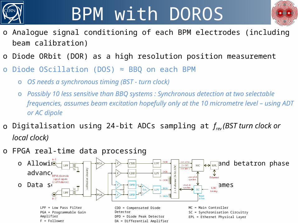
BPM with DOROSo Analogue signal conditioning of each BPM electrodes (including beam calibration)
o Diode ORbit (DOR) as a high resolution position measurement
o Diode OScillation (DOS) ≈ BBQ on each BPM o OS needs a synchronous timing (BST - turn clock)
o Possibly 10 less sensitive than BBQ systems : Synchronous detection at two selectable frequencies, assumes beam excitation hopefully only at the 10 micrometre level – using ADT or AC dipole
o Digitalisation using 24-bit ADCs sampling at frev (BST turn clock or local clock)
o FPGA real-time data processingo Allowing measurement of local betatron coupling and betatron phase advance
o Data serialisation and transmission using UDP frames
CDD = Compensated Diode DetectorDPD = Diode Peak DetectorDA = Differential Amplifier
MC = Main ControllerSC = Synchronisation CircuitryEPL = Ethernet Physical Layer
LPF = Low Pass FilterPGA = Programmable Gain AmplifierF = Follower

BPM with DOROSo The essence of one DOROS unit: o Standalone Architecture using 1U 19” boxes (no VME, no operating system)
o 8 orbit ADC channels, 4 oscillation ADC channelso 2 collimators with 4 buttons each
o 2 regular 4-electrode BPMs
o Ethernet (UDP) data transmission implemented on FPGA
DOROS post LS1o DOROS will be installed on
o New TCTP and TCSP collimators (x18) o In parallel to standard BPM electronics
o Q1 strip-line BPMs in IP1,2,5 & 8 (x8)o Q7 strip-line BPMs in IP1 (x4) for coupling measurementso TOTEM’s button BPMs (x8) in IP5o May be few add. channels - on-going discussions between OP-ABP-BI
o Operation with DOROS in 2015o Evaluate the system performance
o In terms of Resolution, Accuracy, Stability, …. (sensitivity to cross-talks between the two beams in directional strip-line)
o Develop its software and operational procedures, i.e. calibration, gain adjustment, BST synchronisation for oscillation, etc….
o Prepare next phase and upgradeo Possibly deploying up to Q7o …

TUNE Systems in 2012
o 3 sets of pick-ups for each beamo Single or dual plane pick-ups
o Single plane pick-ups not optimum
for coupling measurement because
@ different locations
o Used by 4 independent acquisition systems:o FFT1- “On demand” system used to perform measurements requiring changes in the
acquisition settings and beam excitation, like chromaticity measuremento FFT2-“Continuous gated BBQ” and FFT3-“Continuous BBQ” systems used for feedback
and continuous measurements of tune and coupling o The feedback functionality implies that the acquisition settings are fixedo Continuous system sees all bunches – e.g. observing beam instability
o DEV: Development system used for beam studies and kept as a hot spare

TUNE Systems in 2015
o 2 new dual-plane BPLX pickups – one for each beam (optimize functionalities)o Better coupling measurements with both continuous (BBQ & GBBQ) systemso New “gated excitation” option to excite only the bunches (typically 6) seen by the BBQ
if the natural beam excitation does not provide an acceptable S/N ratio
o New Beam Transfer Function (BTF) measurement (derived from the PLL)o It will be first deployed as a MD tool on the DEV system