commissioning under floor air distribution system a case ... · commissioning under floor air...
TRANSCRIPT
Commissioning Under Floor Air Distribution System A Case Study and Lessons Learned
-or-
Where in the world is Paul Tseng?
Commissioning Under Floor Air Distribution System A Case Study and Lessons Learned
-or-
Where in the world is Paul Tseng?
Presented By
Scott Nelson, P.E. Summit Building Engineering Scott Nelson, P.E. Summit Building Engineering
April 23, 2008
And in association with:
Karl Stum, P.E. Summit Building Engineering
And in association with:
Karl Stum, P.E. Summit Building Engineering

Not here to talk about class 1 or 2
• Definition (mine):
Construction Leakage
any air intended to come up through the raised floor (diffusers OR though spaces in-between floor tiles) that leaves the under floor space by other means.
• Definition (mine):
Construction Leakage
any air intended to come up through the raised floor (diffusers OR though spaces in-between floor tiles) that leaves the under floor space by other means.

The Situation
• 5 Level Office, yet to be built-out
• All floors UFAD, Central Stairs, bathrooms and elevators
• Each floor served by multiple RTU’s, but single zone under floor area
• Salad spinners, plenum return, HW MFT’s for perimeter only
• Under floor static pressure (3 sensors averaged) controls all supply damper positions (per floor), respective duct static controls respective supply fan speed

The Future Layout
• Typical cube farm when ultimately build out
• Under floor zones would be screened for security only
• Typical cube farm when ultimately build out
• Under floor zones would be screened for security only

The RTU/s to Under Floor Delivery System
• Single RTU’s (4 total) serve floors 3, 4 & 5• Single RTU’s (4 total) serve floors 3, 4 & 5

The RTU/s to Under Floor Delivery System
• Several RTU’s serving single floor• Several RTU’s serving single floor
• No floor supplies greater than ~35’ from floor diffuser
• No floor supplies greater than ~35’ from floor diffuser

Equipment
• “Movers Plastic”
• Blue Painters Tape
• Cardboard
• “Movers Plastic”
• Blue Painters Tape
• Cardboard
• Fluke 922 Airflow Meter/Micromanometer• Fluke 922 Airflow Meter/Micromanometer
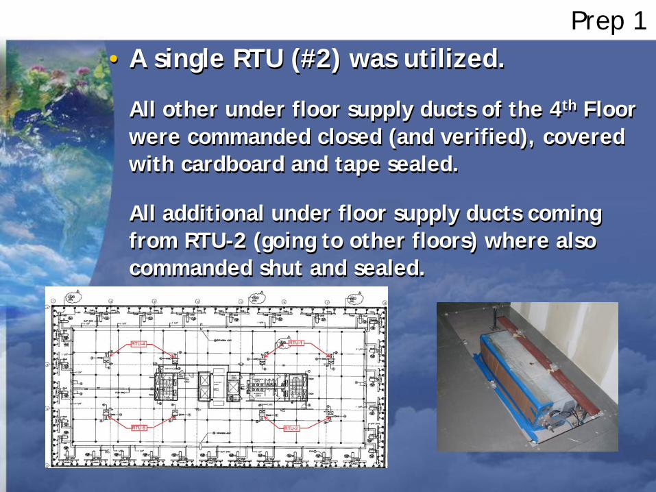
Prep 1• A single RTU (#2) was utilized.
All other under floor supply ducts of the 4th Floor were commanded closed (and verified), covered with cardboard and tape sealed.
All additional under floor supply ducts coming from RTU-2 (going to other floors) where also commanded shut and sealed.
• A single RTU (#2) was utilized.
All other under floor supply ducts of the 4th Floor were commanded closed (and verified), covered with cardboard and tape sealed.
All additional under floor supply ducts coming from RTU-2 (going to other floors) where also commanded shut and sealed.

Prep 2
• Calibrate Sensors
For this floor, 0.051” w.g.
was easily maintained
• Calibrate Sensors
For this floor, 0.051” w.g.
was easily maintained
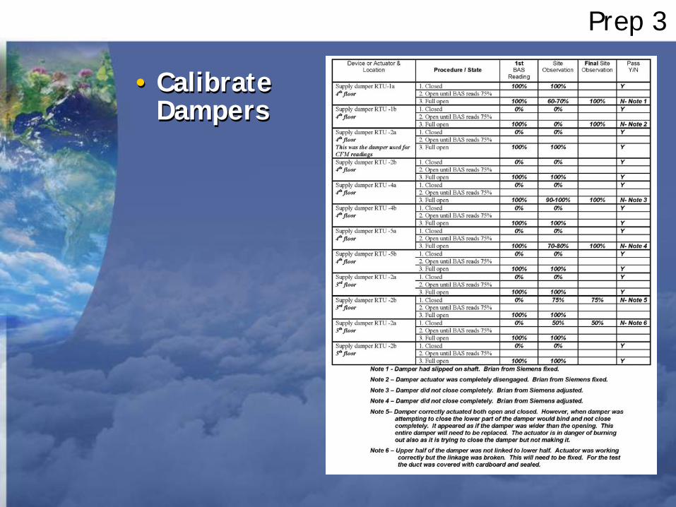
Prep 3
• CalibrateDampers
• CalibrateDampers

Prep 4
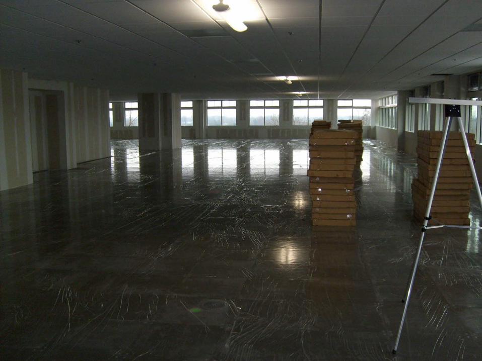
• The entire top of the raised floor was sealed.
Salad spinners, MFT diffusers, cracks in-between tiles, everything.
• The entire top of the raised floor was sealed.
Salad spinners, MFT diffusers, cracks in-between tiles, everything.

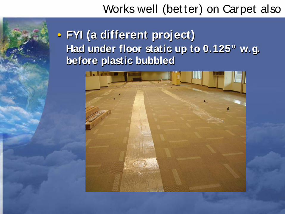
Works well (better) on Carpet also
• FYI (a different project)Had under floor static up to 0.125” w.g. before plastic bubbled
• FYI (a different project)Had under floor static up to 0.125” w.g. before plastic bubbled

With floor and all diffusers sealed -Procedure 1
• RTU-2 was placed in hand mode and was set to 20Hz, which was the minimum allowed by VFD program.
• System was allowed to stabilize.
• Floor and duct seals were checked for integrity.
• RTU-2 was placed in hand mode and was set to 20Hz, which was the minimum allowed by VFD program.
• System was allowed to stabilize.
• Floor and duct seals were checked for integrity.
• VFD speed, under floor static pressure differential and CFM’s at floor supply duct were recorded.
• VFD speed, under floor static pressure differential and CFM’s at floor supply duct were recorded.
There he is! Paul Tseng

Procedure 2
• With floor completely sealed, only 1 supply duct open (100%) and all other supply ducts sealed, the under floor static pressure was read at 0.156” w.g. at BAS and 0.159” w.g. by hand held Fluke.
-CFM’s measured at supply duct were negligible-
• With floor completely sealed, only 1 supply duct open (100%) and all other supply ducts sealed, the under floor static pressure was read at 0.156” w.g. at BAS and 0.159” w.g. by hand held Fluke.
-CFM’s measured at supply duct were negligible-
-with a velocity tip sensor, we could not detect flow (velocity too low)-
Was this 0 CFM Construction Leakage?
-with a velocity tip sensor, we could not detect flow (velocity too low)-
Was this 0 CFM Construction Leakage?
And at ~0.10”w.g. greater than design static pressure?
But the goal was to measure the construction leakage at design static, so, we had to come up with another method…
And at ~0.10”w.g. greater than design static pressure?
But the goal was to measure the construction leakage at design static, so, we had to come up with another method…

Procedure 3
• VFD speed was raised to next increment of 5% (or 25%) and system allowed to stabilize. Again, VFD speed, static pressure differential and CFM were recorded.
• This was continued (VFD speed raised in 5 Hz increments, values recorded) until ~0.650” w.g. was attained.
• VFD speed was raised to next increment of 5% (or 25%) and system allowed to stabilize. Again, VFD speed, static pressure differential and CFM were recorded.
• This was continued (VFD speed raised in 5 Hz increments, values recorded) until ~0.650” w.g. was attained.
Lets add more fuel until something blows up…
And that was fun.
And we measured air flow from the supply duct.
Time to look at the data sheet
But it still didn’t get the answer we were looking for…

Sealed Floor Data
We are here
We will get here shortly

What to do?
• By running the single supply fan VFD at the lowest programmed setting, we could not get below 0.154” w.g. in the under floor.
• So, by introducing known air flows, we figured we could get the under floor static to approximate the design static.
• And, by measuring the air flow across the single supply duct, then subtracting the known quantity of air allowed out of the sealed floor, we could calculate the construction leakage at design static.

Drum roll…
There he is again!
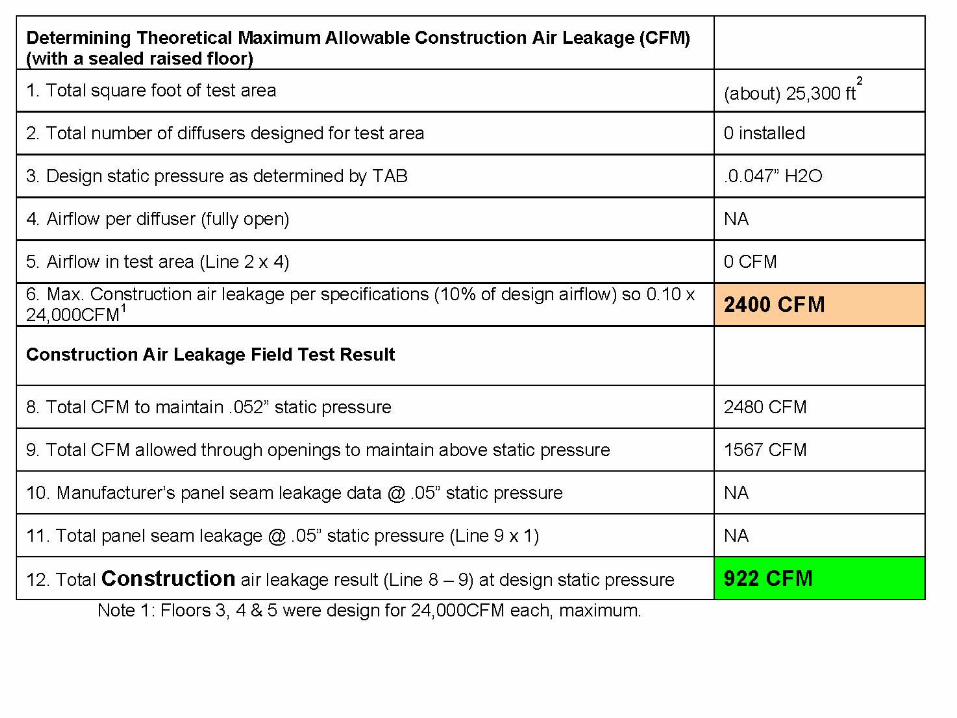
• With 6 diffusers removed, the total CFM coming through those openings (at 20Hz) was 1567.
• At this CFM flow, the under floor static pressure was measured at 0.052” w.g.
• The measured CFM at the supply duct was 2480
• With 6 diffusers removed, the total CFM coming through those openings (at 20Hz) was 1567.
• At this CFM flow, the under floor static pressure was measured at 0.052” w.g.
• The measured CFM at the supply duct was 2480

Much harder to do than I anticipated…
• Do it again except take the plastic off the floor
• Do it again except take the plastic off the floor
Don’t:Clean floor prior to putting this stuff on.Let stay on floor for a minute longer than necessary.
Do:Try and find a plastic that has less adhesive.Bring lots of help.
Lessons Learned…

Prep 1
• All plastic was removed from the floor EXCEPT the plastic covering the diffusers.
• Diffusers removed per prior test were left open
• All plastic was removed from the floor EXCEPT the plastic covering the diffusers.
• Diffusers removed per prior test were left open

With floor unsealed and diffusers sealed -Procedure 1
• RTU-2 was again placed in hand mode and was set to 20Hz, which was the minimum allowed by VFD program.
• System was allowed to stabilize.
• RTU-2 was again placed in hand mode and was set to 20Hz, which was the minimum allowed by VFD program.
• System was allowed to stabilize.
• VFD speed, under floor static pressure differential and CFM’s at floor supply duct were recorded.
• VFD speed, under floor static pressure differential and CFM’s at floor supply duct were recorded.
Not Paul Tseng’s hand

Procedure 2
• At 20Hz and 6 diffuser openings uncovered, the fan could not maintain the 0.052” w.g. design static pressure.
• All 6 diffusers were re-installed and covered with plastic.
• VFD speed was raised 1Hz at a time until under floor static pressure was maintained at approximately the same static pressure as the initial (sealed floor) test ~ 0.051”.

Results
• At 29Hz, RTU-2 was able to maintain the 0.051” w.g. under floor static pressure.
• 2 CFM measurements were made at the RTU- 2a supply duct and averaged.
• At 29Hz, RTU-2 was able to maintain the 0.051” w.g. under floor static pressure.
• 2 CFM measurements were made at the RTU- 2a supply duct and averaged.
Some Conclusions
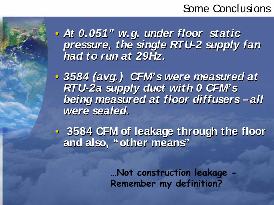
• At 0.051” w.g. under floor static pressure, the single RTU-2 supply fan had to run at 29Hz.
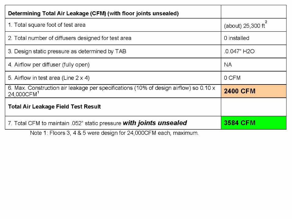
• 3584 (avg.) CFM’s were measured at RTU-2a supply duct with 0 CFM’s being measured at floor diffusers – all were sealed.
• 3584 CFM of leakage through the floor and also, “other means”
• At 0.051” w.g. under floor static pressure, the single RTU-2 supply fan had to run at 29Hz.
• 3584 (avg.) CFM’s were measured at RTU-2a supply duct with 0 CFM’s being measured at floor diffusers – all were sealed.
• 3584 CFM of leakage through the floor and also, “other means”
…Not construction leakage - Remember my definition?

1st Summary
Construction Leakage-OR-
Error in measurements
Construction LeakageAND
Leakage through joints-OR-
All that and error in measurements

What’s it all mean?
So…
If we have 3,584 CFM leaking out with the floor uncovered, and 922 leaking out with the floor sealed, I guess that would mean that 2,662 CFM was coming through the joints in the floor…
And since there is approximately 25,300 sq. ft on this floor, then the leakage though the joints would be ~0.10 CFM/ft2.
Again, so…?
Can we get there another way?
(remind me to talk about error analysis next year)

Another way???
So now we know:How much air comes through the joints, Square footage (and therefore total length of joints)Under floor static pressure
And we can measure joint width…
We measured worst case width 0.007” and best case 0.003” taking numerous samples from the entire floor.We assumed 0.005” as the average of the crack width.
Handy dandy feeler gauge
How did we do when these numbers were entered on the graph presented by Paul Tseng?
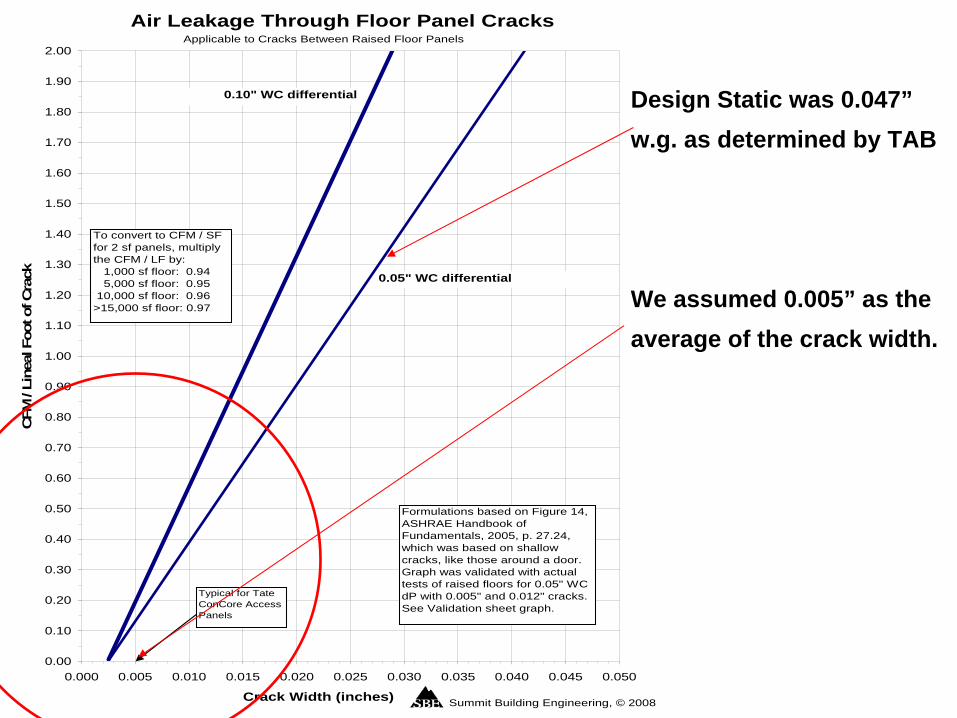
Design Static was 0.047” w.g. as determined by TAB
We assumed 0.005” as the average of the crack width.
Air Leakage Through Floor Panel Cracks
0.00
0.10
0.20
0.30
0.40
0.50
0.60
0.70
0.80
0.90
1.00
1.10
1.20
1.30
1.40
1.50
1.60
1.70
1.80
1.90
2.00
0.000 0.005 0.010 0.015 0.020 0.025 0.030 0.035 0.040 0.045 0.050
Crack Width (inches)
CFM
/ Li
neal
Foo
t of C
rack
Formulations based on Figure 14, ASHRAE Handbook of Fundamentals, 2005, p. 27.24, which was based on shallow cracks, like those around a door. Graph was validated with actual tests of raised floors for 0.05" WC dP with 0.005" and 0.012" cracks. See Validation sheet graph.
Summit Building Engineering, © 2008
To convert to CFM / SF for 2 sf panels, multiply the CFM / LF by: 1,000 sf floor: 0.94 5,000 sf floor: 0.95 10,000 sf floor: 0.96>15,000 sf floor: 0.97
Applicable to Cracks Between Raised Floor Panels
0.05" WC differential
0.10" WC differential
Typical for Tate ConCore Access Panels

To get CFM/sq, multiply CFM/LF by 0.97(~0.12 CFM/LF) X 0.97 = 0.116 CFM/sq.ft.
0.00
0.10
0.20
0.30
0.40
0.000 0.005 0From graphical results we get approximately 0.116 CFM/sq.ft,From measurements we get approximately 0.10 CFM/sq.ft

Summary 2
• Are the graphical results close?
~well, (within 14%) somewhat*,
• Are the graphical results reasonable?
~guess that’s a judgment call
• Are the graphical results cheaper, faster, able to be performed at different stages of construction without major activity interruption and grumbling sub contractors?
~well, yeah.
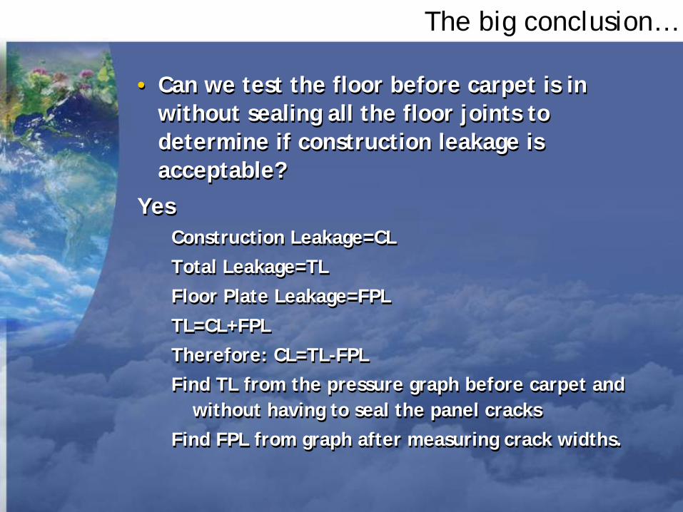
The big conclusion…
• Can we test the floor before carpet is in without sealing all the floor joints to determine if construction leakage is acceptable?
YesConstruction Leakage=CLTotal Leakage=TLFloor Plate Leakage=FPLTL=CL+FPLTherefore: CL=TL-FPLFind TL from the pressure graph before carpet and
without having to seal the panel cracks Find FPL from graph after measuring crack widths.
• Can we test the floor before carpet is in without sealing all the floor joints to determine if construction leakage is acceptable?
YesConstruction Leakage=CLTotal Leakage=TLFloor Plate Leakage=FPLTL=CL+FPLTherefore: CL=TL-FPLFind TL from the pressure graph before carpet and
without having to seal the panel cracksFind FPL from graph after measuring crack widths.

Fire Away !Fire Away !
Scott Nelson • 503/805-9113 • [email protected]
Karl Stum • 360/573-5700 • [email protected]
Any rude questions will be handled by Paul Tseng