committee draft oiml r 80/2cd date: december … a determination of the ... the metrological...
TRANSCRIPT

TC 8/ SC 1: Static volume and mass measurement
Committee DRAFT OIML R 80/2CD Date: December 2015 Reference number: TC8_SC1_P6_N004 TC8_SC1_P6_N005
OIML/TC 8/SC 1/p 6 Circulated to P- and O-members and liaison international bodies and external organizations for:
Title: OIML R 80 “Road and rail tankers with level gauging” Part 2 - Metrological controls and tests Part 3 - Test Report format
vote (P-members only) and comments by July 1, 2016
Convener: Germany
comments (O-members and liaisons) by: July 1, 2016
Information only
X
X

INTERNATIONAL OIML R 80-2 RECOMMENDATION Edition 201x (E)
Road and rail tankers with level gauging
Part 2: Metrological controls and tests
Camions et wagons équipés de citernes avec mesurage de niveau
Partie 2: Contrôles métrologiques et essais
OIM
L R
80-
2 Ed
ition
201
x (E
)
ORGANISATION INTERNATIONALE DE MÉTROLOGIE LÉGALE
INTERNATIONAL ORGANIZATION
OF LEGAL METROLOGY

Page 2 of 46 OIML TC8/SC1/p6/R 80-2 CD2
Draft of December 2015
Contents
Foreword Terminology
1 Scope
2 Metrological control 2.1 General 2.2 Type evaluation 2.3 Equipment under test for type evaluation 2.4 Initial verification 2.5 Subsequent verification
3 Performance tests for type approval of electronic measuring systems
3.1 General 3.2 Reference conditions 3.3 Environmental classification 3.4 Performance tests
4 Bibliography
Annex A Determination of the pipe volume Annex B Examples for the tests of 2.3 through 2.5

Page 3 of 46 OIML TC8/SC1/p6/R 80-2 CD2
Draft of December 2015
Foreword The International Organization of Legal Metrology (OIML) is a worldwide, intergovernmental organization whose primary aim is to harmonize the regulations and metrological controls applied by the national metrological services, or related organizations, of its Member States. The main categories of OIML publications are:
• International Recommendations (OIML R), which are model regulations that establish the metrological characteristics required of certain measuring instruments and which specify methods and equipment for checking their conformity; the OIML Member States shall implement these Recommendations to the greatest possible extent;
• International Documents (OIML D), which are informative in nature and intended to harmonize and improve work in the field of the metrology;
• International Guides (OIML G), which are also informative in nature and which are intended to give guidelines for the application of certain requirements to legal metrology;
• International Basic Publications (OIML B), which define the operating rules of various OIML structures and systems.
OIML Draft Recommendations, Documents and Guides are developed by Project Groups linked to Technical Committees or Subcommittees which comprise representatives from OIML Member States. Certain international and regional institutions also participate on a consultation basis. Cooperative agreements have been established between the OIML and certain institutions, such as ISO and the IEC, with the objective of avoiding contradictory requirements. Consequently, manufacturers and users of measuring instruments, test laboratories, etc. may simultaneously apply OIML publications and those of other institutions. International Recommendations, Documents, Guides and Basic Publications are published in English (E) and translated into French (F) and are subject to periodic revision. Additionally, the OIML publishes or participates in the publication of Vocabularies (OIML V) and periodically commissions legal metrology experts to write Expert Reports (OIML E). Expert Reports are intended to provide information and advice, and are written solely from the view of the CIML. Thus, they do not necessarily represent the views of OIML. This publication – reference OIML R 80-2, edition ... – was developed by the OIML subcommittee TC 8/SC 1 Static volume and mass measurement. It was approved for final publication by online voting and will be submitted to the International Conference of Legal Metrology in ….. for formal sanction. OIML publications may be downloaded from OIML web site in the form of PDF files. Additional information on OIML Publications may be obtained from the Organization’s headquarters: Bureau International de Métrologie Légale 11, rue Turgot - 75009 Paris - France Telephone: 33 (0)1 48 78 12 82 Fax: 33 (0)1 42 82 17 27 E-mail: [email protected] Internet: www.oiml.org

Page 4 of 46 OIML TC8/SC1/p6/R 80-2 CD2
Draft of December 2015
TERMINOLOGY The terms and definitions given in R 80-1 apply in this Recommendation R80-2. In addition, the following terms and definitions are used: Cut-off point Level where the level gauge sensor is able to measure the minimum filling height at the maximum inclination of the tank. Note: Below this level a measurement of the filling height cannot be guaranteed. Residual volume Liquid content of the compartment including pipework at the cut-off point level. 1 SCOPE This Recommendation is applicable to the type evaluation of complete road and rail tankers with level gauging and for type evaluation of the following separate components:
- the measuring tank; - the level gauging device; - the indicating device.
Initial and subsequent verifications in accordance with this Recommendation are applicable to complete road and rail tankers with level gauging, as defined in OIML R 80-1. This Recommendation sets out details of the test program, principles, equipment and procedures to be used for type evaluation, initial and subsequent verification testing. Some of the provisions of this Recommendation may also apply to ancillary devices, if required by national regulations. 2 METROLOGICAL CONTROL 2.1 General 2.1.1 In general (depending on national or regional legislation), legal metrological control can consist of type approval, initial and subsequent verification, and metrological supervision. 2.1.2 The essential elements of a measuring system, mainly those listed below, may be subject to separate type evaluation: - measuring tank; - level gauging device; - indicating device. 2.1.3 The results of metrological control may be used for purposes of safety control.

Page 5 of 46 OIML TC8/SC1/p6/R 80-2 CD2
Draft of December 2015
2.2 Type evaluation 2.2.1 The application for type evaluation of a road or rail tanker shall include the following documents:
- the documentation prescribed in 6.2 of R 80-1; - a description giving the technical characteristics and the principle of operation; - a description of the electronic devices with drawings, diagrams and general software
information explaining their characteristics and operation; - operating instructions; - documentation or other evidence that supports the assumption that the design and
characteristics of the measuring instrument comply with the requirements of this Recommendation; and
- drawings representing - a general assembly of the road or rail tanker; - a general assembly of the measuring tank, including its compartments; - a general assembly and function of the level gauging system; - auxiliary and ancillary installations, as appropriate; - details of the dome, reinforcing elements and discharge device(s); - identification plate; - the location of seals and verification marks;
- if available type evaluation certificate for the measuring compartment / tank; - if available type evaluation certificate gauge measuring device.
2.2.2 The body responsible for type evaluation decides about the number of specimens necessary for the type evaluation tests. In case the applicant wants to have approved several versions or measuring ranges, the body responsible for type evaluation decides which version(s) and range(s) shall be supplied. Several tests can be carried out in parallel on different specimen. In this case, the body responsible for type evaluation decides which version or measuring range will be subjected to a specific test. If a specimen does not pass a specific test and as a result, it has to be modified or repaired, the applicant shall carry out this modification to all the instruments supplied for test. If the testing laboratory has sound reasons to fear that the modification has negative influence on tests that already had a positive result, these tests shall be repeated. 2.2.3 The type evaluation of a road or rail tanker includes the following operations:
- external inspection; - leak test; - pressure test, if required; - calibration; - check on temperature dilatation of the tank; - check on shape invariability; - check on invariability of capacity in service; - check on correct filling; - check on complete discharge; - check on sensitivity and expansion volume; - check of ancillary devices and of the inclination correction (if any); - check on rest volumes.

Page 6 of 46 OIML TC8/SC1/p6/R 80-2 CD2
Draft of December 2015
Note: - Each tank/compartment is unique and has to be calibrated individually. Typically, the calibration and - depending on the concrete case - some of the other tests listed were carried out in connection with the initial verification. - The results of any test performed only for safety issues may be used.
2.2.4 If a pressure test is required, it shall be performed before the volumetric calibration. 2.2.5 The type evaluation of the gauge measuring system includes the following examinations, if applicable:
- units; - accuracy classes and their symbols; - measuring ranges; - scale intervals or resolution; - performance tests of the electronic parts. - presentation of the measured value; - adjustment facilities; - protection against fraud; - checking facilities; - durability protection; - software; - durable recording of measuring results; - printing device; - storage of measured value; - inscriptions; - instruction manual; - sealing and stamping.
Note: A separate type evaluation certificate for the gauge measuring system may be issued 2.2.6 As a rule, tests will be carried out on the complete measuring system. Simulation of any part of the system tested should be avoided. If this is not possible, for instance for components which cannot be tested either partially or with the whole system, all parts of the measuring system that can be affected by the influence factor or disturbance shall play an active role in the measurements If the size or configuration of the measuring system does not lend itself to testing as a whole unit, or if only a separate device of the measuring instrument is concerned, the tests, or certain tests, shall be carried out on the devices (modules) separately, provided that, in the case of tests with the devices in operation, these devices are included in a simulated setup, sufficiently representative of its normal operation.
2.2.7 Type approval certificate The following information shall appear on the type approval certificate:
- name and address of the issuing authority and name of responsible person; - name and address of the applicant of the type approval certificate; - name and address of the manufacturer, if it is not the applicant; - principal metrological and technical characteristics; - type approval mark; - date of issue and period of validity;

Page 7 of 46 OIML TC8/SC1/p6/R 80-2 CD2
Draft of December 2015
- information on the location of marks for type approval, initial verification and sealing
(e.g. a picture or drawing); - list of documents accompanying the type approval certificate; - specific remarks; - the version and signature of the metrological part of the evaluated software, if
applicable, and - sufficient information to perform the tests during initial and subsequent verification.
2.2.8 Modification of an approved type 2.2.8.1 The applicant of the type approval shall inform the body responsible for the approval of any modification or addition, which concerns the metrological part of an approved type. 2.2.8.2 Modifications and additions shall be subject to a supplementary type approval when they influence, or are likely to influence, the measurement results or the measuring system’s regulatory conditions of use. The body having approved the initial type shall decide to which extent the examinations and tests described below shall be carried out on the modified type in relation to the nature of the modification. Note: The manufacturer shall present a written evidence (of this fact) issued by approval body, when
introducing the product on market. 2.2.8.3 If the body having approved the initial type judges that the modifications or additions are not likely to influence the measurement results, this body shall allow in writing the modified measuring systems to be presented for initial verification without granting a supplementary type approval. 2.2.8.4 A new or supplementary type approval must be carried out whenever the modified type no longer fulfils the provisions of the initial type approval. A modification of the metrological part of the software requires a new software version with signature which has to be stated in the addendum of the approval. 2.3 Equipment under test for type evaluation For components of the measuring system that cannot be fully tested within the whole system (e.g. temperature sensors), it is recommended to test them separately and to document the test results in a suitable way and in accordance with the applicable national regulations. 2.3.1 Test of volume-conversion and temperature-measuring devices 2.3.1.1 Analogue temperature sensor and conversion device may be tested independently of each other. The conversion device may be tested by simulation of the sensor. In this case the permissible errors of the temperature sensor shall not exceed 3/5 and of the conversion device 2/5 of the requirements of 5.1.5 of R80-1, respectively. 2.3.1.2 The function of the volume conversion software shall be checked at least at three temperatures for each product or product group by using simulated values. Recommended test points are minimum (or value near 0 °C), reference and maximum temperatures of the product. The test volume shall be at least 10 000 liters.

Page 8 of 46 OIML TC8/SC1/p6/R 80-2 CD2
Draft of December 2015
Maximum permissible errors and significant faults on quantities of liquid indications applicable to calculators, positive or negative, are equal to one-tenth of the maximum permissible error defined in line A of Table 2 of R 80-1. 2.3.1.3 During type evaluation, the correct functioning of the checking facilities has to be checked. 2.3.2 Test of inclination sensors The inclination sensors shall be examined for a matrix-like type of inclinations within the range the measuring system is intended to use for, in both (longitudinal and transverse) directions, as well as in all possible (i.e. four) simultaneous inclinations in both directions. The accuracy of these examinations shall be so that the requirements of OIML R80-1 5.5.4 are met. Note: Experience has shown that for common tank shapes these requirements will be met if the
deviation of inclination indication is not greater than 0.1° in any of the directions to be tested.
Recommended number of test points is 9. Maximum deviation of all of these points shall be recorded in the test report.
2.3.3 Test of floats 2.3.3.1 General 2.3.3.1.1 For type evaluation, at least one float of each type has to be tested at reference conditions at least with one liquid close to the minimum density and one liquid close to the maximum density within the permissible density range of the intended liquids and the liquid generally used for tank calibration (e.g. water) if the liquid is different from the liquid close to the maximum density. The respective immersion depth shall be in the intended height range of the float (cylindrical area). 2.3.3.1.2 For measuring systems with corresponding corrections, the change of the immersion depth within the permissible density range of each intended liquid is determined by calculation against the dimensions and weight of the float. The immersion depth of the float should be calculated at the maximum permissible density and at the minimum permissible density of each liquid. The deviation between the immersion depth at the maximum permissible density and at the minimum permissible density of each liquid shall not exceed the value given in table 8 of R80-1. 2.3.3.1.3 For measuring systems not fitted with corresponding corrections, the immersion depth is determined at least with one liquid close to the minimum density and one liquid close to the maximum density within the permissible density range of the intended liquids and the liquid generally used for tank calibration (e. g. water) if the liquid is different from the liquid close to the maximum density, by calculation against the dimensions and weight of the float. The deviation between the immersion depth at the maximum permissible density and at the minimum permissible density of the density range of the intended liquids should be included in the uncertainty evaluation of the level measurement. The expanded uncertainty shall not exceed values given in table 6 of R80-1. 2.3.3.1.4 At type evaluation, one float should be defined as reference float for further use in initial verification and in the case of a necessary replacing of a float during use.

Page 9 of 46 OIML TC8/SC1/p6/R 80-2 CD2
Draft of December 2015
2.3.3.1.5 To avoid influences on the metrological properties, the floats need not be marked. 2.3.3.2 Test of the float construction for type evaluation 2.3.3.2.1 Chemical resistance The manufacturer shall submit documentation proving the adequate chemical resistance of the float material. This documentation shall include the evaluation of the typical fluids and conditions for its later use. These fluids and conditions shall not have any influence on the specified physical characteristics of the float. 2.3.3.2.2 Pressure resistance For tanks with a working pressure not exceeding 0.5 bar the float has to be tested for 10 min. with 0.75 bar. In the other cases the float has to be tested for 10 min. with 1.5 of the tank working pressure for which it is intended. The float has to withstand this pressure test without deformation, cracks or change of the physical characteristics. 2.3.3.2.3 Adoption of float to the rod The float has to be tested at the maximum inclination of the later use that it is not stuck on the level gauge rod. 2.3.3.2.4 Temperature influence on immersion depth The influence of the liquid temperature to the immersion depth of the float has to be tested when it is not sufficient to show in a numerical calculation that the influence of the temperature has no significant influence on the accuracy of the whole system. The immersion depth of the float shall not change by more than the value given in Table 8 of R80-1. An example of a test stand for the determination of the immersion depth of a float by reference float method is given in the informative Annex A. 2.3.4 Test of dipstick pipes for ultrasound systems The mechanical dimensions of the reference marks of the dipstick pipes shall be tested, for example by clamping the pipe into a gauge and comparing the distance of the reference marks from the reference edges of the gauge with the values given on the gauge. The permissible deviations shall not exceed the values given in table 4 of R 80-1. 2.3.5 Test of computer or controller The evaluation of the conversion device shall be part of the type approval procedure. Its accuracy, the correct functioning of the checking facilities, etc. have to be checked. 2.3.6 Separate test of an indicating device The checking facilities of the indicating devices have to be checked, for instance by connecting/disconnecting the indicating device.

Page 10 of 46 OIML TC8/SC1/p6/R 80-2 CD2
Draft of December 2015
2.4 Initial verification 2.4.1 General 2.4.1.1 Before the first putting into use an initial verification has to be done to show compliance to R80-1 and the type approval certificate. 2.4.1.2 Initial verification can only be done on a calibrated tank. The calibration of the tank, leak tests and pressure tests had to be executed and documented before the initial verification. Note: The procedure of tank calibration is described in informative Annex B.
2.4.1.3 For leakage and pressure compliance test evidence according the regulations of safe transport on the road or rail of portable tanks is acceptable and sufficient. 2.4.1.4 All test equipment used shall have the required accuracy and must, to the extent possible, be traceable to SI. The use of simulators or computer-aided measuring facilities is permitted. 2.4.1.5 The use of simulators or computer-aided measuring facilities is permitted. 2.4.1.6 It shall be ensured that all components (e.g. valve control) are working properly. 2.4.2 Metrological tests 2.4.2.1 Pre-verification Components of the measuring system which can be only tested at the factory or with a lot of effort on site need to be pre-verified. For pre-verified components no additional tests on site are necessary. It has to be stated that each of these components fulfils the requirements of the type approval certificate. If applicable, the following components should be tested at the factory:
- Temperature sensor: The accuracy of the temperature sensor has to be checked at three different temperatures. Based on this tests it has to be stated that the temperature sensor fulfils the accuracy required by the liquid temperature range of the measuring system or fulfil the requirements stated in type approval certificate of the measuring system. - Inclination sensor: The accuracy of the level sensor has to be checked in longitudinal and transverse directions and in all possible simultaneous inclinations in both directions. The zero-degree deviation, if any, has to be documented. Based on this tests it has to be stated that the inclination sensor fulfil the accuracy required by type approval certificate of the measuring system. The correct direction of mounting stated on the housing has to be checked. - Float: The dimensions and weight of the float shall be within the permissible tolerances specified in the type approval certificate. The immersion depth offset of the individual float shall be determined in relation to the reference float of the same or equivalent type. Note: The knowledge of the immersion depth offset of the float is necessary only for the case to prevent a complete new calibration of the tank or compartment after replacing the float. This offset DDfloat can be determined by comparing the indications of the reference float (Index m) and of the float to be tested (Index float): DDfloat=Dfloat-Dm (see Annex A)

Page 11 of 46 OIML TC8/SC1/p6/R 80-2 CD2
Draft of December 2015
All test results have to be documented. At least the serial number, the test fluid and the method of determination of the immersion depth offset together with other individual characteristics have to be recorded in the accompanying document of the float. Based on this tests it has to be stated that the float fulfil the accuracy required by type approval certificate of the float. To avoid influences on the metrological properties, the floats need not be marked.
- Dipsticks for float systems for full compartment delivery The dipstick has to be tested with a filling height simulator in 10 points regularly distributed on its measuring range in both directions. The maximum permissible error on height measurement (MPEh) is given by the following formula:
( )BASMPE −⋅⋅= 5h
where A and B are the numerical values specified in Table 2, lines A and B of R80-1 for the relevant accuracy class. S is the sensitivity given in table 5 of R80-1.
- Dipsticks for float systems for partial compartment delivery The dipstick has to be tested with a filling height simulator at three different heights. The expanded uncertainty of the measurement shall be less than the values given in table 6 of R80-1. An example of the calculation of this uncertainty is given in Annex E. - Ultrasound level sensor: The ultrasound level sensors are checked with a shortened reference pipe, containing a well-defined reference echo mark in the level measuring tube at a distance of 350 … 500 mm. The reference tube shall be fixed to the sensor to be tested. The arrangement shall be immersed in de-ionised, gas-free water, taking care to remove any gas bubbles which may be trapped in the tubes. When connected to a reference controller, the deviation of the level reading obtained from the controller and the distance of the echo mark shall be less than the value specified in the type approval certificate. - Ultrasound dipstick pipe: The mechanical dimensions of the reference marks of the dipstick pips shall be tested. Based on this tests it has to be stated in a document that the permissible deviations are as specified in the type approval certificate of the measuring system.
Unless stated otherwise, all instruments or parts having undergone one of these separate tests for initial verification shall be marked and, if necessary, sealed. 2.4.2.2. Tests of no-pre-verified components If components of the measuring system have not been pre-verified the corresponding tests shall be performed during initial verification. 2.4.2.3 Visual inspection The following items have to be checked:
- external and internal appearance of the tank or compartment(s), damage(s); - completeness of identification plate; - compliance with the specifications of the type examination certificate including the version; of the software (modules) and signatures used, if appropriate; - stored values of the metrological relevant parameters as defined in the type examination certificate; - all sealing points according the sealing plan;

Page 12 of 46 OIML TC8/SC1/p6/R 80-2 CD2
Draft of December 2015
- presence and completeness of the measuring system document.
2.4.2.4 Accuracy tests Before these tests, the tank and its associated pipework has to be completely empty. The following tests are the basic of accuracy tests for a dip stick measuring system. If additional tests are required to show compliance to R80-1, it has to be defined in the type approval certificate. 2.4.2.4.1 Test of the volume in normal position Test the volume in normal position inside 0° ± 0.2°. The test volume is chosen of not higher than 2 times MMQ of the measuring system. The tank compartment has to be filled with at least 90% of its nominal volume. Step by step the compartment has to be emptied by the amount of the test volume. The latest step shall compromise a complete empting of the tank. If this step is smaller than the test volume, the tank has to be filled up to deliver to the test volume. If such a standard capacity is not available it could also be done by volume stacking.
- Permissible deviation for test volume of 1 time MMQ: ± 2 times the accuracy class of the measuring system
- Permissible deviation for test volume ≥ 2 times MMQ: ± accuracy class of the measuring system
Note: This test can also be done by using an appropriate volumetric liquid meter.
2.4.2.4.2 Test of the residual volume The residual volume shall be tested, if it is not done during accuracy test. To test the correct set up of the residual volume, a completely empty compartment and its associated pipework is filled up with the nominal volume of the standard capacity measure (see R120 [1]). The compartment will be discharged completely and the delivered volume has to be within the stated accuracy. This volume consists of a metered part by the level gauge sensor and the fixed part of the residual volume. Note: This test can also be done by using an appropriate volumetric liquid meter.
2.4.2.4.3 Leak test of the tank The tank shall be leak-tested according to clause 5.2.2.2 of R 80-1 2.4.2.4.4 Test of the volume in dependence of the inclination Each tank compartment has to be tested with 15% to 30% and with 70% to 90% of its nominal compartment volume. The volumes in the following positions have to be determined:
- Longitudinal position with an inclination between +2° to +3° (front side up) - Longitudinal position with an inclination between -2° to -3° (back side up) - Transversal position with an inclination between +2.5° to +5° (right side up) - Transversal position with an inclination between -2.5° to -5° (left side up) - The inclination of the respectively other position has to be inside ± 0.5°.
The error of the volume during these tests does not exceed three-fifth (3/5) of the MPE of the volume in normal position.

Page 13 of 46 OIML TC8/SC1/p6/R 80-2 CD2
Draft of December 2015
2.4.2.4.5 Test of the influence of adjacent compartments Fill up a compartment to 30% and afterwards the adjacent compartment to 90% of its nominal volume. The volume of the compartment shall not change by more than one-third (1/3) of the MPE when the adjacent compartment is filled or emptied. 2.4.2.5 Test of the height measurement This test concerns the level gauging device which displays only height (or ullage). The maximum permissible error on height measurement (MPEh) after installation is given by the following formula:
( )BASMPE −⋅⋅=10h
where A and B are the numerical values specified in Table 2, lines A and B of R80-1 for the relevant accuracy class. S is the sensitivity given in table 5 of R80-1. Each level gauging system is checked on 3 points regularly distributed on its measuring range in both directions by comparison with a mechanical dipstick. If the dipstick satisfied the pre-verification test (see 2.4.2.1) the level gauging device could be verified, after installation, in one point situated close to the nominal capacity by comparison with a mechanical dipstick. 2.4.2.6 Test of computer or controller For initial verification, the software (modules) used as well as their signature shall be checked for compliance with the versions stated in the type approval certificate. If present, the protection function (e.g. electronic sealing) for the data of legal relevance shall be checked. 2.5 Subsequent verification 2.5.1 Subsequent verification is subject to national regulations. The following actions are recommended:
2.5.1.1 Visual inspection The visual inspection comprises the inspection of the following items: For the measuring tank:
- external damage (if damage to a measuring compartment cannot be safely excluded, the operator may be requested to clean the compartment so that the compartment can safely be inspected from inside);
- compliance with the type approval certificate. For the level gauging system:
- compliance of the parameters or signature(s) relevant to verification with those at the time of initial verification;
- compliance of the version of the software (modules) used as well of their signature with the type approval certificate or supplements;
- availability of the measuring system document; - identification of the incorporated components;

Page 14 of 46 OIML TC8/SC1/p6/R 80-2 CD2
Draft of December 2015
- mechanical damage of the level sensors; - presence of measuring system type plate; - availability of operating instructions.
2.5.1.2 Volumetric test using a volume standard The principles of testing are described in Annex D as an example, assuming accuracy class 0.5 and a reference container volume of 1 000 liters. It is sufficient however, to prove that three measurements of 1 000 liters each, taken at filling states of approximately 90% and 50%, and when emptying the compartment completely, are within a deviation of ± 0.5% of the measured quantity (i.e. 5 liters). If this limit is exceeded in one or several of these tests, further deliveries of 1 000 liters each may be performed until 80% of the minimum delivered quantity of the compartment under test is reached or exceeded. The deviation between the sum of these successive measurements and the sum of the standard readings shall be within ± 0.5%. Checking of the temperature sensor according to Annex D.3 should be carried out simultaneously with these tests. 2.5.1.3 Volumetric test using a reference meter The test is carried out in analogy to Annex D.4. The testing quantities shall be equal to the minimum measured quantity. 2.5.1.4 Check of pipework volumes for measuring systems with collector The pipework system including the collector is subject to a simplified test, which consists of the second test step described in Annex C, preceded by an initial flushing as described.
The maximum permissible error for this measurement deviation is ± 0.5 % of the minimum measuring quantity of the measuring compartment selected for this test. 2.5.1.5 Check of inclination correction The test shall be carried out as described in Annex D.5 but only at one level near 30 % or 70 % of the nominal volume of each compartment. 2.5.1.6 Seals Missing or damaged seals shall be renewed by the verification officer, possibly based on the user’s application. 2.5.2 Recommended actions after replacement of components for measuring systems for
full compartment delivery/receipt In case of a replacement of components of the measuring system under legal control, the actions below are recommended: 2.5.2.1 Actions on replacement of the controller or computer
- Separate test of new device according to 2.3.5; - entry of the new data into the measuring system document.

Page 15 of 46 OIML TC8/SC1/p6/R 80-2 CD2
Draft of December 2015
2.5.2.2 Actions on replacement of a simple indicating device
- Separate test of the indicating device according to 2.3.6 2.5.2.3 Actions on replacement of dipsticks for float systems
- Comparison with a mechanical dipstick at a level close to nominal capacity; - entry of the new data into the measuring system document.
2.5.2.4 Actions on replacement of a sensor/float
- Comparison with a mechanical dipstick at a level close to nominal capacity; - entry of the new data into the measuring system document.
2.5.3 Recommended actions after replacement of components for measuring systems for
partial compartment delivery/receipt In case of a replacement of a component of the measuring system under legal control, the actions below are recommended: 2.5.3.1 Actions on replacement of the controller or computer
- Separate test of new device according to 2.3.5; - entry of the new data into the measuring system document; - single volume measurement by verification authority with quantity of about MMQ
delivered from the random compartment, check of the indicated and corrected volume; - comparison and evaluation of parameters.
2.5.3.2 Actions on replacement of a simple indicating device - Separate test of the indicating device according to 2.3.6 2.5.3.3 Actions on replacement of dipsticks for float systems
- Separate test of new dipstick for float system according to 2.4.2.1; - entry of the new dipstick correction values into the level gauging system; - entry of the new data into the measuring system document; - single volume measurement by verification authority, quantity of about (1 to 2) x MMQ
delivered from the compartment fitted with new dipstick, check of the volume at working conditions, unless otherwise specified in the type approval;
- comparison and evaluation of parameters. 2.5.3.4 Actions on replacement of a sensor/float
- Separate test of a new float according to 2.4.2.1; - entry of the new float correction values into the level gauging sy stem; - entry of the new data into the measuring system document; - single volume measurement by verification authority, quantity of about (1 to 2) x MMQ
delivered from the compartment fitted with new float, check of the volume at working conditions, unless otherwise specified in the type approval;
- comparison and evaluation of parameters. 2.5.3.5 Actions on replacement of dipsticks for ultrasound systems

Page 16 of 46 OIML TC8/SC1/p6/R 80-2 CD2
Draft of December 2015
- Separate test of new dipstick for ultrasound systems according to 2.4.2.1; - entry of the new correction values into the level gauging system; - entry of the new data into the measuring system document, if applicable; - single volume measurement by verification authority, quantity of about (1 to 2) x MMQ
delivered from the compartment fitted with the new dipstick, check of the volume at working conditions, unless otherwise specified in the type approval;
- comparison and evaluation of parameters. 2.5.3.6 Actions on replacement of a temperature sensor
- Separate test of a new temperature sensor according to 2.3.1; - entry of the new sensor parameters into parameter list; - entry of the new data into the measuring system document; - temperature measurement by verification authority during delivery of a random quantity
from the relevant compartment; - recording and comparison of the delivery temperature with certified thermometer,
comparison and evaluation of parameters. 2.5.4 Recommended actions after repair or corrections of the measuring system 2.5.4.1 Compilation of a new calibration table for a measuring After a new calibration table has been compiled for one or several tank compartments (recalibration of a tank or compartment, e.g. after repair of the tank or a deformation after accident), the verification of the measuring system is no longer valid. 2.5.4.2 For the following verification, all re-calibrated measuring compartments shall be tested as for initial verification. The re-examination of the pipe-work volumes may be dispensed with if these have not changed. Prior to the due date the compartments for which no new calibration tables have been compiled need not be subsequently verified due to the repair. After the repaired compartments have been checked, the measuring system shall be provided with a seal stating the original period of validity of the verification (if applicable, depending on national legislation). 2.5.4.3 If the repair was carried out within the scope of a subsequent verification, the repaired compartments will be treated as in initial verification and the other compartments as in subsequent verification.

Page 17 of 46 OIML TC8/SC1/p6/R 80-2 CD2
Draft of December 2015
3 PERFORMANCE TESTS FOR TYPE APPROVAL OF ELECTRONIC MEASURING SYSTEMS 3.1 General This sub-clause defines the program of performance tests intended to verify that electronic measuring systems perform and function as intended in a specified environment and under specified conditions. Each test indicates, where appropriate, the reference conditions for determining the intrinsic error. These tests supplement any other prescribed test. When the effect of one influence quantity is being evaluated, all other influence quantities are to be held relatively constant, at values close to reference conditions. 3.2 Reference conditions Ambient temperature: 15 ºC to 35 ºC Relative humidity: 25 % to 75 % Atmospheric pressure: 84 kPa to 106 kPa Mains (power supply) voltage: Nominal voltage (Unom) Mains (power supply) frequency: Nominal frequency (fnom) During each test, the temperature shall not vary by more than 5 ºC and the relative humidity shall not vary by more than 10 % within the reference range. The test laboratory shall have the ability to authorize different reference conditions as long as these conditions are fully documented with an explanation of why the alternate reference conditions were used, the implications of the alternate reference conditions, and the effects on the testing results. 3.3 Environmental classification For each performance test, typical test conditions are indicated which correspond to the climatic, mechanical and electromagnetic environmental conditions to which the tankers are usually exposed. According to OIML D 11 [2] the following classes are recommended
- Climatic environment: Class H3 This class applies to instruments or parts of instruments used in open air locations excluding those in extreme climate zones such as polar and desert environments.
- Mechanical environment: Class M3 This class applies to locations where the level of vibration and shock is high or very high, e.g. where measuring instruments are directly mounted on machines, conveyor belts, etc.
- Electromagnetic environment: Class E3 This class applies to measuring instruments powered by the battery of a vehicle and exposed to electromagnetic disturbances which correspond to those likely to be found in any environment not considered hazardous for the general public. According to these classes, severity levels given by the following Table 1 shall be applied.

Page 18 of 46 OIML TC8/SC1/p6/R 80-2 CD2
Draft of December 2015
Table 1: Severity levels for the performance tests
Kind of performance tests
Test description Evaluation 1) OIML D 11 Severity level2)
Climatic 3.4.1 Dry heat I MPE 10.1, Table 6 3)
3.4.2 Cold I MPE 10.1, Table 7 3)
3.4.3 Damp heat, cyclic (condensing) D NSFa 10.2, Table 9 2
Mechanical 3.4.4 Vibration (random) I MPE 11.1, Table 15 2
Electrical, general
3.4.5 Radiated electromagnetic fields D NSFd 13.2, Table 32 3
3.4.6 Conducted currents generated by RF EM fields
D NSFd 13.2, Table 31 3
3.4.7 Electrostatic discharge D NSFd 13.3, Table 35 3
3.4.8 Power frequency magnetic field D NSFd 13.1, Table 30 4
3.4.9 Bursts (transients) on signal, data and control lines
D NSFd 12.4, Table 28 3
Electrical, AC mains voltage 4)
3.4.10 AC mains voltage variation I MPE 12.2, Table 20 1
3.4.11 Surges on AC lines D NSFd 12.3; Table 27 3
3.4.12 AC mains voltage dips, short interruptions and voltage variations
D NSFd 12.3, Table 23 2
3.4.13 Bursts (transients) on AC mains D NSFd 12.3, Table 26 3
Electrical, internal battery 5)
3.4.14 Low voltage of internal battery I MPE 14.1, Table 36 1
Electrical, power from external 12 V and 24 V road vehicle batteries 6)
3.4.15.1Voltage variations I MPE 14.2, Table 37 C/F
3.4.15.2 Electrical transient conduction along supply lines
D NSFd 14.2, Table 38 IV
3.4.15.3 Electrical transient conduction via lines other than supply lines
D NSFd 14.2, Table 39 IV
1) I - Influence factor D - Disturbance MPE - Maximum permissible error
NSFa - No significant fault shall occur after the disturbance NSFd - No significant fault shall occur during the disturbance
2) Severity levels are in accordance with OIML D11 and IEC standards mentioned in the following
clause 3.4

Page 19 of 46 OIML TC8/SC1/p6/R 80-2 CD2
Draft of December 2015
3) Test levels for temperature
The thermal conditions in which measuring systems and ancillary devices are used vary considerably. These are highly dependent on the place on earth, ranging from arctic to tropical regions. Therefore, no classes combining low and high temperature limits have been described in this Recommendation.
Note: While manufacturers select the test levels for type evaluation, national (or regional) legislation will generally set the requirements for acceptable lower and upper temperature limits (taking into account the test levels in 3.4.1 and 3.4.2).
4) only applicable for systems powered by AC mains 5) only applicable for systems powered by internal battery 6) only applicable for systems powered by road vehicle battery
3.4 Performance tests
The following tests need only be carried out where, as a result of the physical principle of the measuring system or a part of it, a significant influence may be expected. If a test is not carried out the reason shall be noted in the test report. Note: The test procedures have been given in condensed form, for information only, and are adapted
from the referenced IEC-publications. Before conducting the test, the applicable publication should be consulted.

Page 20 of 46 OIML TC8/SC1/p6/R 80-2 CD2
Draft of December 2015
3.4.1 Dry heat Table 2
Applicable standards IEC 60068-2-2 [3], IEC 60068-3-1 [4]
Test method Exposure to dry heat (non-condensing)
Applicability General
Object of the test Verification of compliance with the provisions in 5.7.1.1 of R80-1under conditions of high temperature
Test procedure in brief
The test comprises exposure to the specified high temperature under “free air” conditions for a 2-hour period after the EUT has reached temperature stability.
The change in temperature shall not exceed 1 °C/min during heating up and cooling down.
The absolute humidity of the test atmosphere shall not exceed 20 g/m3. When testing is performed at temperatures below 35 °C, the relative humidity shall not exceed 50 %.
The EUT shall be tested
- at the reference temperature of 20 °C after 1 hour conditioning;
- at the specified high temperature, 2 hours after temperature stabilization;
- after 1 hour recovery of the EUT at the reference temperature of 20 °C.
During the tests, the EUT shall be in operation.
Simulated inputs are permitted.
Tests shall be performed at a fixed level
One of the following test levels may be specified:
Test level index 1 2 3 4 5
Temperature 30 °C 40 °C 55 °C 70 °C 85 °C
Number of test cycles One cycle
Permitted maximum deviation
All functions shall operate as designed.
All errors measured during the application of the influence factor shall be within the maximum permissible errors.

Page 21 of 46 OIML TC8/SC1/p6/R 80-2 CD2
Draft of December 2015
3.4.2 Cold
Table 3
Applicable standards IEC 60068-2-1 [5], IEC 60068-3-1 [4] Test method Exposure to low temperature Applicability General
Object of the test Verification of compliance with the provisions 5.7.1.1.of R 80-1 under conditions of low ambient air temperature
Test procedure in brief
The test comprises exposure to the specified low temperature under “free air” conditions for a 2-hour period after the EUT has reached temperature stability.
The change of temperature shall not exceed 1 °C/min during heating up and cooling down.
IEC specifies that the power to the EUT shall be switched off before the temperature is raised.
The EUT shall be tested:
- at the reference temperature of 20 °C after 1 hour conditioning,
- at the specified low temperature, 2 hours after temperature stabilization,
- after 1 hour recovery of the EUT at the reference temperature of 20 °C.
During the tests, the EUT shall be in operation.
Simulated inputs are permitted.
Tests shall be performed at a fixed level
one of the following test levels may be specified:
Test level index 1 2 3 4
Temperature +5 °C -10 °C -25 °C -40 °C
Number of cycles One cycle
Permitted maximum deviation
All functions shall operate as designed.
All errors measured during the application of the influence shall be within the maximum permissible errors.

Page 22 of 46 OIML TC8/SC1/p6/R 80-2 CD2
Draft of December 2015
3.4.3 Damp heat, cyclic (condensing)
Table 4
Applicable standards IEC 60068-2-30 [6], IEC 60068-3-4 [7]
Test method Exposure to damp heat with cyclic temperature variation
Applicability Applicable only for outdoor used equipment
Object of the test Verification of compliance with the provisions in 5.7.1.23 of R 80-1 under conditions of high humidity combined with cyclic temperature changes
Test procedure in brief
The test comprises exposure to cyclic temperature variation between 25 °C and the appropriate upper temperature of 55 °C, maintaining the relative humidity above 95 % during the temperature changes and during the phases at the low temperature, and at or above 93 % at the upper temperature phases.
Condensation is expected to occur on the EUT during the temperature rise.
The 24-hour cycle comprises:
- temperature rise during 3 hours,
- temperature maintained at upper value until 12 hours from the start of the cycle,
- temperature lowered to lower temperature level within a period of 3 to 6 hours, the declination (rate of fall) during the first hour and a half being such that the lower temperature level would be reached in a 3 hour period,
- temperature maintained at the lower level until the 24 h period is completed.
The stabilizing period before and recovery period after the cyclic exposure shall be such that the temperature of all parts of the EUT is within 3 °C of its final value.
During the tests, the EUT shall be in operation.
Simulated inputs are permitted.
After the application of the disturbance and recovery the EUT shall be tested at a fixed level.
Test severities Severity level 2: 55 °C
Duration Two cycles
Restrictions During the application of the disturbance, the power supply of the EUT is in switch-off mode.
Permitted maximum deviation
After the application of the disturbance and recovery, all functions shall operate as designed.
All errors shall be within the maximum permissible errors.

Page 23 of 46 OIML TC8/SC1/p6/R 80-2 CD2
Draft of December 2015
3.4.4 Vibration (random)
Table 5
Applicable standard IEC 60068-2-47 [8], IEC 60068-2-64 [9], (IEC 60068-3-8 [10])
Test method Exposure to random vibration
Applicability General
Object of the test Verification of compliance with the provisions in 5.7.1.1 of R 80-1 under conditions of random vibration
Test procedure in brief
The test comprises exposure of the EUT to vibration.
The EUT shall be tested in three, mutually perpendicular axes mounted on a rigid fixture by its normal mounting means.
After the application of the disturbance and recovery the EUT shall be tested at a fixed level.
Test severity Severity level 2
Total frequency range 10 – 150 Hz
Total RMS level 7 m·s-2
ASD level 10-20 Hz 1 m2·s-3
ASD level 20-150 Hz –3 dB/octave
Number of axis 3
Duration per axis For each of the orthogonal directions, the vibration exposure time shall be 2 minutes.
Restrictions During the application of the influence quantity the power supply of the EUT is in switch-off mode.
Permitted maximum deviation
After the influence factor is removed, all functions shall operate as designed.
All errors shall be within the maximum permissible errors after the influence factor is removed..

Page 24 of 46 OIML TC8/SC1/p6/R 80-2 CD2
Draft of December 2015
3.4.5 Radiated radio frequency electromagnetic fields
Table 6
Applicable standards IEC 61000-4-3 [11]; IEC 61000-4-20 [12]
Test method Exposure to radiated radio frequency electromagnetic fields
Applicability Only applicable for electronic measuring instruments containing active electronic circuits
Object of the test Verification of compliance with the provisions in 5.7.1.2 of R 80-1 under conditions of exposure to electromagnetic fields.
Test procedure in brief
The EUT is exposed to electromagnetic fields with the required field strength and the field uniformity as defined in the referred standard.
The level of field strength specified refers to the field generated by the unmodulated carrier wave.
The EUT shall be exposed to the modulated wave field. The frequency sweep shall be made only pausing to adjust the RF signal level or to switch RF-generators, amplifiers and antennas if necessary. Where the frequency range is swept incrementally, the step size shall not exceed 1 % of the preceding frequency value.
The dwell time of the amplitude modulated carrier at each frequency shall not be less than the time necessary for the EUT to be exercised and to respond, but shall in no case be less than 0.5 s.
Adequate EM fields can be generated in facilities of different type and setup the use of which is limited by the dimensions of the EUT and the frequency range of the facility.
The expected most critical frequencies (e.g. clock frequencies) shall be analyzed separately.
During the tests, the EUT shall be in operation. Simulated inputs are permitted. Tests shall be performed at a fixed level.
Test severity Severity level 3.
Frequency range (26) 80–3000 MHz 10 V/m
Modulation 80 % AM, 1 kHz, sine wave
Permitted maximum deviation
During the disturbance, either significant faults do not occur or checking facilities detect a malfunction and act upon it in accordance with 5.7.3 of R 80-1 when significant faults occur.
Notes
- IEC 61000-4-3 only specifies test levels above 80 MHz. For frequencies in the lower range the test methods for conducted radio frequency disturbances are recommended (test 3.4.6)
- However, for EUT having no mains or other input port available, the lower limit of radiation test should be 26 MHz taking into account that the test specified in 3.4.6 cannot be applied (refer to Annex H of IEC 61000-4-3). In all other cases, both 3.4.5 and 3.4.6 shall apply

Page 25 of 46 OIML TC8/SC1/p6/R 80-2 CD2
Draft of December 2015
3.4.6 Conducted (common mode) currents generated by RF EM fields
Table 7
Applicable standard IEC 61000-4-6 [13]
Test method Injection of RF currents representing exposure to RF electromagnetic fields
Applicability Only applicable for electronic measuring instruments containing active electronic circuits and equipped with external electrical wiring (mains power, signal, data and control lines)
Object of the test Verification of compliance with the provisions in 5.7.1.2 of R 80-1 while exposed to electromagnetic fields.
Test procedure in brief
An RF EM current, simulating the influence of EM fields shall be coupled or injected into the power ports and I/O ports of the EUT using coupling/decoupling devices as defined in the referred standard.
The characteristics of the test equipment consisting of an RF generator, (de-)coupling devices, attenuators, etc. shall be verified before connecting the EUT.
During the tests, the EUT shall be in operation.
Simulated inputs are permitted.
Tests shall be performed at a fixed level
Test severity
Severity level 3
10 V (emf) for the RF amplitude (50 Ω) Frequency range 0.15 – 80 MHz
Permitted maximum deviation
During the disturbance, either significant faults do not occur or checking facilities detect a malfunctioning and act upon it in accordance with .7.3. of R 80-1 when significant faults occur.
Notes
- If the EUT is composed of several elements, the tests shall be performed at each extremity of the cable if both of the elements are part of the EUT.
- For the frequency range 26 – 80 MHz, the testing laboratory can either carry out tests according to 3.4.5 or according to 3.4.6. But in case of dispute, the results according to 3.4.6 shall prevail.

Page 26 of 46 OIML TC8/SC1/p6/R 80-2 CD2
Draft of December 2015
3.4.7 Electrostatic discharge
Table 8
Applicable standard IEC 61000-4-2[14]
Test method Exposure to electrostatic discharge (ESD)
Applicability Applicable to all electronic measuring instruments
Object of the test Verification of compliance with the provisions in 5.7.1.2 of R80-1 in case of direct exposure to electrostatic discharges or such discharges in the neighborhood of the EUT.
Test procedure in brief
The test comprises exposure of the EUT to electrical discharges.
An ESD generator as defined in the referred standard shall be used and the test setup shall comply with the dimensions, materials used and conditions as specified in the referred standard. Before starting the tests, the performance of the generator shall be verified.
At least 10 discharges per preselected discharge location shall be applied. For EUTs not equipped with a ground terminal, the EUT shall be fully discharged between discharges. The time interval between successive discharges shall be at least 1 second.
Contact discharge is the preferred test method. Air discharge is far less defined and reproducible and therefore shall be used only where contact discharge cannot be applied.
Direct application: In the contact discharge mode to be carried out on conductive surfaces, the electrode shall be in contact with the EUT before activation of the discharge. In such a case the discharge spark occurs in the vacuum relays of the contact discharge tip.
On insulated surfaces only the air discharge mode can be applied. The EUT is approached by the charged electrode until a spark discharge occurs.
During the tests, the EUT shall be in operation.
Simulated inputs are permitted. Tests shall be performed at a fixed level.
Test severity Severity level 3
Test voltage 8 kV for air discharges 6 kV for contact discharges
Number of test cycles
At each test point, at least ten direct discharges shall be applied at intervals of at least ten seconds between discharges, during the same measurement or simulated measurement.
For indirect discharges, a total of ten discharges shall be applied on the horizontal coupling plane and a total of ten discharges of the vertical coupling plane.
Permitted maximum deviation
During the disturbance, either significant faults do not occur or checking facilities detect a malfunctioning and act upon it in accordance with 4.7.3 of R 80-1 when significant faults occur.

Page 27 of 46 OIML TC8/SC1/p6/R 80-2 CD2
Draft of December 2015
3.4.8 Power frequency magnetic field
Table 9
Applicable standard IEC 61000-4-8[15]
Test method Exposure to power frequency electromagnetic fields (50 Hz or 60 Hz)
Applicability General
Object of the test Verification of compliance with the provisions in 5.7.1.2 of R80-1 under conditions of power frequency magnetic field (50 Hz or 60 Hz)
Test procedure in brief The test comprises exposure of the EUT to a power frequency magnetic field (50 Hz or 60 Hz)
Test severity Severity level 4
Magnetic field strength 30 A/m for continuous field
300 A/m for short duration (1 – 3 s)
Number of test cycles
At each test point, at least ten direct discharges shall be applied at intervals of at least ten seconds between discharges, during the same measurement or simulated measurement.
For indirect discharges, a total of ten discharges shall be applied on the horizontal coupling plane and a total of ten discharges of the vertical coupling plane.
Permitted maximum deviation
During the disturbance, either significant faults do not occur or checking facilities detect a malfunctioning and act upon it in accordance with 4.7.3 of R 80-1 when significant faults occur.

Page 28 of 46 OIML TC8/SC1/p6/R 80-2 CD2
Draft of December 2015
3.4.9 Burst (transients) on signal, data and control lines
Table 10
Applicable standards IEC 61000-4-4 [16]
Test method Introducing transients on signal, data and control lines
Applicability
Only applicable for electronic measuring instruments containing active electronic circuits which during operation are permanently or temporarily connected to external electrical signal, data and/or control lines.
This test is not applicable to equipment powered by a road vehicle battery.
Object of the test Verification of compliance with the provisions in 5.7.1.2 of R 80-1 during conditions where electrical bursts are superimposed on I/O and communication ports.
Test procedure in brief
A burst generator as defined in the referred standard shall be used. The characteristics of the generator shall be verified before connecting the EUT.
The test comprises exposure to bursts of voltage spikes for which the output voltage on 50 Ω and 1000 Ω load are defined in the referred standard.
Both positive and negative polarity of the bursts shall be applied.
The duration of the test shall not be less than 1 min for each amplitude and polarity.
A capacitive coupling clamp as defined in the standard shall be used for the coupling of the bursts into the I/O and communication lines.
The bursts are applied during all the time necessary to perform the test; for that purpose more bursts than indicated above may be necessary.
During the tests, the EUT shall be in operation.
Simulated inputs are permitted.
Tests shall be performed at a fixed level.
Test severity
Severity level 3
1kV for the amplitude (peak value)
Repetition rate 5 kHz
Restrictions Tests on signal lines are applicable only for I/O signal, data and control ports, with a cable length exceeding 3 m (as specified by the manufacturer).
Permitted maximum deviation
During the disturbance, either significant faults do not occur or checking facilities detect a malfunctioning and act upon it in accordance with 4.7.3 of R 80-1 when significant faults occur

Page 29 of 46 OIML TC8/SC1/p6/R 80-2 CD2
Draft of December 2015
3.4.10 AC mains voltage variation
Table 11
Applicable standards IEC/TR3 61000-2-1 [17], IEC 61000-4-1 [18]
Test method Applying low and high level AC mains power voltage (single phase)
Applicability Applicable for measuring instruments which are temporarily or permanently connected to an AC mains power network while in operation.
Object of the test Verification of the compliance with the provisions in 5.7.1.1 of R 80-1 under conditions of varying AC mains power voltage.
Test procedure in brief The test comprises exposure of the EUT to the specified power supply condition for a time period sufficient for achieving temperature stability and subsequently performing the required measurements.
Test severity Severity level: 1
Mains voltage Upper limit Unom1 + 10 %
Lower limit Unom2 – 15 %
Permitted maximum deviation
All functions shall operate as designed and all the errors measured during the application of the influence factor shall be within the maximum permissible errors.
Notes - For three phase mains power supplies, the voltage variation is applicable for each of the phases successively.
- The values of Unom are those marked on the measuring instrument. If a range is specified, Unom1 concerns the highest and Unom2 the lowest value in the range. If only one nominal mains voltage value (Unom) is specified then Unom1 = Unom2= Unom

Page 30 of 46 OIML TC8/SC1/p6/R 80-2 CD2
Draft of December 2015
3.4.11 Surges on AC lines
Table 12
Applicable standard IEC 61000-4-5 [19]
Test method Introducing electrical surges on the mains power lines
Applicability Applicable for measuring instruments which are temporarily or permanently connected to an AC mains power network while in operation.
Object of the test Verification of compliance with the provisions in 5.7.1.2 during conditions where electrical surges are superimposed on the mains voltage
Test procedure in brief A surge generator as defined in the referred standard shall be used. The characteristics of the generator shall be verified before connecting the EUT.
The test comprises exposure to surges for which the rise time, pulse width, peak values of the output voltage/current on high/low impedance load and minimum time interval between two successive pulses are defined in the referred standard.
At least 3 positive and 3 negative surges shall be applied.
On AC mains supply lines the surges shall be synchronized with the AC supply frequency and shall be repeated such that the injection of surges on all 4 phase shifts: 0°, 90°, 180° and 270° with the mains frequency is covered.
The injection network circuit depends on the applicable conductor and is defined in the referred standard.
Test severities Severity level 3
AC line to line 1.0 kV
AC line to ground 2.0 kV
Permitted maximum deviation
After the disturbance, either significant faults do not occur or checking facilities detect a malfunctioning and act upon it in accordance with 5.7.3 of R 80-1 when significant faults occur.

Page 31 of 46 OIML TC8/SC1/p6/R 80-2 CD2
Draft of December 2015
3.4.12 AC mains voltage dips, short interruptions and variations
Table 13
Applicable standards IEC 61000-4-11 [20], IEC 61000-6-1 [21], IEC 61000-6-2 [22]
Test method Introduction short-time reductions in mains voltage using the test setup defined in the applicable standard
Applicability Applicable for measuring instruments with rate d input current less than 16 A per phase which are temporarily or permanently connected to an AC mains power network while in operation
Object of the test Verification of compliance with the provisions in 5.7.1.2 of R 80-1 under conditions of short time mains voltage reductions
Test procedure in brief A test generator is to be used which is suitable to reduce the amplitude of the AC mains voltage for the required period of time.
The performance of the test generator shall be verified before connecting the EUT.
The mains voltage reduction tests shall be repeated 10 times with intervals of at least 10 seconds between the tests.
Test severities Severity level 2
Voltage dips
Test a Reduction to 0 %
Duration 0.5 cycles
Test b Reduction to 0 %
Duration 1 cycles
Test c Reduction to 40 %
Duration 10/12 (1) cycles
Test d Reduction to 70 %
Duration 25/30 (1) cycles
Test e Reduction to 80 %
Duration 250/300 (1) cycles
Short interruptions Reduction to 0 %
Duration 250/300 (1) cycles
Notes (1) Values applicable for 50 Hz / 60 Hz respectively
Permitted maximum deviation
During the disturbance, either significant faults do not occur or checking facilities detect a malfunctioning and act upon it in accordance with 5.7.3 of R 80-1 when significant faults occur.

Page 32 of 46 OIML TC8/SC1/p6/R 80-2 CD2
Draft of December 2015
3.4.13 Bursts (transients) on AC mains
Table 14
Applicable standard IEC 61000-4-4 [16]
Test method Introduction transients on mains power lines
Applicability Applicable for measuring instruments which are temporarily or permanently connected to mains power network while in operation.
Object of the test Verification of compliance with the provisions in 5.7.1.2 during conditions where electrical bursts are superimposed on the mains voltage
Test procedure in brief A burst generator as defined in the referred standard shall be. The characteristics of the generator shall be verified before connecting the EUT.
The test comprises exposure to bursts of voltage spikes for which the output voltage on 50 Ω and 1 000 Ω load are defined in the referred standard.
Both positive and negative polarity of the bursts shall be applied.
The duration of the test shall not be less than 1 min for each amplitude and polarity. The injection network on the mains shall contain blocking filters to prevent the burst energy being dissipated in the mains.
Test severities Severity level 3
Amplitude (peak value) 2 kV
Repetition rate 5 kHz
Permitted maximum deviation
During the disturbance, either significant faults do not occur or checking facilities detect a malfunctioning and act upon it in accordance with 5.7.3 of R 80-1 when significant faults occur.

Page 33 of 46 OIML TC8/SC1/p6/R 80-2 CD2
Draft of December 2015
3.4.14 Low voltage of internal battery (not connected to mains power)
Table 15
Applicable standards No standard is available
Test method Applying minimum supply voltage
Applicability Applicable to all measuring instruments supplied by internal battery
Object of the test Verification of compliance with the provisions in 5.7.1.1 of R 80-1 during low battery voltage
Test procedure The test comprises exposure of the EUT to the specific low the battery level condition during a period sufficient for achieving temperature stability and for performing the required measurements. The maximum internal impedance of the battery and the minimum battery supply voltage level (Umin) shall be specified by the manufacturer of the instrument.
If an alternative power supply source is used instead of the internal battery, for instance in bench testing, the internal impedance of the specified type of battery shall also be simulated.
The alternative power supply shall be capable of delivering sufficient current at the applicable supply voltage.
The test sequence is as follows:
- Let the power supply stabilize at a voltage as defined within the rated operating conditions and apply the measurement and/or loading condition.
Record:
- 1. The data defining the actual measurement conditions including date, time and environmental conditions,
2. the actual power supply voltage
- Perform measurements and record the error (-s) and other relevant performance parameters
- Verify compliance with 5.7.1.1 of R80-1
- Repeat the above procedure with actual supply voltage at Umin and again at 0.9 Umin
- Verify compliance with the requirements
Test severities Severity level 1:
Lower limit of the voltage
The lowest voltage at which the EUT functions properly according to the specifications.
Number of cycles At least one test cycle for each functional mode
Permitted maximum deviation
All functions shall operate as designed and all the errors measured during the application of the influence factor shall be within the maximum permissible errors.

Page 34 of 46 OIML TC8/SC1/p6/R 80-2 CD2
Draft of December 2015
3.4.15 Tests for power from road vehicle batteries
3.4.15.1 Voltage variations
Table 16
Applicable standard ISO 16750-2 [23]
Test method Variation in supply voltage
Applicability Applicable to all measuring instruments supplied by the internal battery of a vehicle and charged by use of a combustion engine driven generator
Object of the test Verification of compliance with the provisions in 5.7.1.1 of R 80-1 under conditions of high voltage (for example while charging) and low battery voltage.
Test procedure in brief The test comprises exposure to the specified maximum and minimum power supply voltage conditions for a period of time sufficient for achieving temperature stability and performing the required measurements at these conditions.
Test severity Severity levels C and F
Voltage
Nominal battery voltage 12 V Lower limit 9 V Upper limit 16 V
Nominal battery voltage 24 V Lower Limit 16 V Upper limit 32 V
Permitted maximum deviation
At both the upper supply voltage level and the lower supply voltage level:
- all functions shall operate as designed.
- all errors shall be within the maximum permissible errors.

Page 35 of 46 OIML TC8/SC1/p6/R 80-2 CD2
Draft of December 2015
3.4.15.2 Electrical transient conduction along supply lines
Table 17
Applicable standard ISO 7637–2 [24] § 5.6.2: Test pulse 2a + 2b § 5.6.3: Test pulse 3a + 3b
Test method Electrical transient conduction along supply lines.
Applicability Applicable to all measuring instruments which while in operation are supplied by the internal battery of a vehicle which may at the same time be charged by use of a combustion engine driven generator
Object of the test
Verification of compliance with the provisions 5.7.1.2 of R 80-1 under the following conditions:
- transients due to a sudden interruption of current in a device connected in parallel with the device under test due to the inductance of the wiring harness (pulse 2a);
- transients from DC motors acting as generators after the ignition is switched off (pulse 2b);
- transients on the supply lines which occur as a result of the switching processes (pulses 3a and 3b).
Test procedure in brief
The test comprises exposure to disturbances on the power voltage by direct coupling into the supply lines.
During the tests, the EUT shall be in operation.
Simulated inputs are permitted. Tests shall be performed at a fixed level.
Test severity Severity level IV
Test pulse Pulse voltage Us
Unom = 12 V Unom = 24 V
2a
+50 V +50 V
2b
+10 V +20 V
3a
–150 V –200 V
3b
+100 V +200 V
Notes
Test pulse 2b is only applicable when the electrical power circuitry of the measuring instrument can be interrupted by the master switch of the car and as a consequence is not permanently connected to the battery of the car. This test will therefore be applicable in all situations where the manufacturer of the measuring instrument has not specified that the instrument is to be connected directly to the battery.
Permitted maximum deviation
During the disturbances 2a, 3a and 3b and after the disturbance 2b, either significant faults do not occur or checking facilities detect a malfunctioning and act upon it in accordance with 5.7.3 of R 80-1 when significant faults occur.

Page 36 of 46 OIML TC8/SC1/p6/R 80-2 CD2
Draft of December 2015
3.4.15.3 Electrical transient conduction via lines other than supply lines
Table 18
Applicable standard ISO 7637–3 [25] § 3.5.1; Fast transient test pulses a and b
Test method Electrical transient conduction along lines other than supply lines.
Applicability Only applicable to analogue I/O cabling of modular measuring instruments installed in vehicles
Object of the test Verification of compliance with the provisions 5.7.1.2 of R 80-1 under conditions of transients which occur on other lines than supply lines as a result of the switching processes (pulses a and b)
Test procedure in brief
The test comprises exposure to bursts of voltage spikes by capacitive and inductive coupling via lines other than supply lines.
During the tests, the EUT shall be in operation.
Simulated inputs are permitted.
Test severity Severity level IV
Pulse voltage Us
Unom = 12 V Pulse a -60 V
Pulse b +40 V
Unom = 24 V Pulse a –80 V
Pulse b +80 V
Permitted maximum deviation
During the disturbance, either significant faults do not occur or checking facilities detect a malfunctioning and act upon it in accordance with 5.7.3 of R 80-1 when significant faults occur.

Page 37 of 46 OIML TC8/SC1/p6/R 80-2 CD2
Draft of December 2015
4 BIBLIOGRAPHY
[1] OIML R 120 (2010): Standard capacity measures for testing measuring systems for liquids other
than water. [2] OIML D 11: General requirements for measuring instruments – Environmental conditions. 2013 [3] IEC 60068-2-2 (2007-07): Environmental testing. Part 2: Test methods. Test B. Dry heat. [4] IEC 60068-3-1 (2011-08): Environmental testing. Part 3: Supporting documentation and
guidance. Section 1: Cold and dry heat tests. [5] IEC 60068-2-1 (2007-03): Environmental testing. Part 2: Test methods. Test A. Cold. [6] IEC 60068-2-30 (2005-08): Environmental testing. Part 2: Test methods. Test Db: Damp heat,
cyclic (12 + 12 hour cycle). [7] IEC 60068-3-4 (2001-08): Environmental testing. Part 3: Supporting documentation and
guidance. Section 4: Damp heat tests. [8] IEC 60068-2-47 (2005-04): Environmental testing. Part 2: Test methods. Section 47: Mounting of
specimens for vibration, impact and similar dynamic tests. [9] IEC 60068-2-64 (2008-04): Environmental testing. Part 2: Test methods. Section 64: Test Fh:
Vibration, broad-band random and guidance. [10] IEC 60068-3-8 (2003-08): Environmental testing. Part 3: Supporting documentation and
guidance. Section 8: Selecting amongst vibration tests [11] IEC 61000-4-3 (2010-04): Basic EMC Publication – Electromagnetic compatibility (EMC). Part
4: Testing and measurement techniques. Section 3: Radiated, radio-frequency, electromagnetic field immunity test.
[12] IEC 61000-4-20 (2010-08): Basic EMC Publication – Electromagnetic compatibility (EMC). Part
4: Testing and measurement techniques. Section 20: Emission and immunity testing in transverse electromagnetic (TEM) waveguides.
[13] IEC 61000-4-6 (2013-10/cor1:2015): Basic EMC Publication – Electromagnetic compatibility
(EMC) Part 4: Testing and measurement techniques, Section 6: Immunity to conducted disturbances, induced by radio frequency fields.
[14] IEC 61000-4-2 (2008-12): Basic EMC Publication - Electromagnetic compatibility (EMC) Part 4:
Testing and measurement techniques, Section 2: Electrostatic discharge immunity test.
[15] IEC 61000-4-8 (2009-09): Basic EMC Publication - Electromagnetic compatibility (EMC) Part 4: Testing and measurement techniques. Section 8: Power frequency magnetic field immunity test.
[16] IEC 61000-4-4 (2012-04): Basic EMC Publication - Electromagnetic compatibility (EMC) Part 4:
Testing and measurement techniques. Section 4: Electrical fast transient/burst immunity test. [17] IEC/TR 61000-2-1 (1990-05): Electromagnetic compatibility (EMC). Part 2: Environment.
Section 1: Description of the environment - Electromagnetic environment for low frequency conducted disturbances and signalling in public power supply systems

Page 38 of 46 OIML TC8/SC1/p6/R 80-2 CD2
Draft of December 2015
[18] IEC 61000-4-1 (2006-10): Basic EMC publication - Electromagnetic compatibility (EMC). Part
4: Testing and measurement techniques. Section 1: Overview of IEC 61000-4 series. [19] IEC 61000-4-5 (2014-05): Basic EMC publication - Electromagnetic compatibility (EMC). Part
4: Testing and measurement techniques. Section 5: Surge immunity test. [20] IEC 61000-4-11 (2004-03): Basic EMC publication - Electromagnetic compatibility (EMC). Part
4: Testing and measuring techniques. Section 11: Voltage dips, short interruptions and voltage variations immunity tests.
[21] IEC 61000-6-1 (2005-03): Basic EMC publication - Electromagnetic compatibility (EMC). Part
6: Generic standards. Section 1: Immunity for residential, commercial and light-industrial environments.
[22] IEC 61000-6-2 (2005-01): Basic EMC publication - Electromagnetic compatibility (EMC). Part
6: Generic standards. Section 2: Immunity for industrial environments. [23] ISO 16750-2 (2012): Road vehicles – Environmental conditions and testing for electrical and
electronic equipment; Part 2: Electrical loads. [24] ISO 7637-2 (2011): Road vehicles - Electrical disturbance from conducting and coupling. Part 2:
Electrical transient conducting along supply lines only. [25] ISO 7637-3 (2007): Road vehicles - Electrical disturbance by conducting and coupling - Part 3:
Passenger cars and light commercial vehicles with nominal 12 V supply voltage and commercial vehicles with 24 V supply voltage - Electrical transient transmission by capacitive and inductive coupling via lines other than supply lines.
[26] OIML G 1-100: Evaluation of measurement data – Guide to the expression of uncertainty in
measurement. Joint Committee for Guides in Metrology JCGM, Edition 2008, Corrected Version 2010

Page 39 of 46 OIML TC8/SC1/p6/R 80-2 CD2
Draft of December 2015
ANNEX A
EXAMPLE OF A TEST STAND FOR THE DETERMINATION OF THE IMMERSION DEPTH OF A FLOAT BY REFERENCE FLOAT METHOD
(Informative)
A.1 Description of the test stand A test setup for measuring the float immersion depth is shown in figure C1. Two level gauges of the same type of later use are affixed in a liquid-tight container with a support for each level float which had been fixed at the bottom. The spacers are necessary for a good reference surface for the floats. The level gauge is used to measure the level of float under the same conditions of later use.
Fig. C1: Test setup for measuring the float immersion depth
A.2 Calibrating the test set up with a reference float The value A1 has to be determined when the float is lying on the support by reading the value of the level gauge. Then the container is filled with test fluid. The value A2 can be taken from the level gauge after the calming of the fluid. The immersion depth can now be calculated with the following formula
2hm ALD −=
Level gauge 2 has to be checked in the same way and should give the same results for the immersion depth Dm. The immersion depth of the reference float is calibrated and is used as a master float.

Page 40 of 46 OIML TC8/SC1/p6/R 80-2 CD2
Draft of December 2015
A.3 Determination immersion depth of the float Level gauge 1 with the reference float serves now as the master for determining the immersion depth of the floats used in the measuring system. Level gauge 2 is for the float that has to be calibrated. The values A1 and B1 are taken when the container is empty. The values A2 and B2 are taken after filling the container with test fluid. The immersion depth of the float Dfloat can be calculated by
22mfloat ABDD −+= A.4 Immersion depth offset The immersion depth offset of the float to be tested is determined as follows:
mfloatfloat DDD −=D

Page 41 of 46 OIML TC8/SC1/p6/R 80-2 CD2
Draft of December 2015
ANNEX B
TANK CALIBRATION
(Informative)
B.1 General B.1.1 Each tank/compartment is unique and has to be calibrated. If the tank consists of several compartments every compartment has to be calibrated. An empty compartment can be used to store the liquid of the compartment for calibration. B.1.2 Each tank/compartment has to be calibrated together with the corresponding level sensor system according to clause 5.5 of R 80-1. The expanded uncertainty of the determination of volume of liquid in tank for initial verification shall not exceed one-third of the maximum permissible error according to R80-1, Table 2. The expanded uncertainty shall be estimated according to the Guide to the expression of uncertainty in measurement [26] with k=2. B.1.3 It is not permitted to use calibration data based on construction documents or tanks/compartments of similar construction.
B.2 External conditions The tank for calibration has to be fixed with supports on the ground at normal position. During the calibration every movement or inclination of the tank has to be avoided. The tank has to be filled up with liquid to the nominal volume. During the calibration process the measuring system store a tank capacity table with pairs of level/volume values for the tank. B.3 Minimum measured quantity The minimum measured quantity MMQ shall be specified for each measuring compartment in accordance with 5.1.7 of R 80-1 unless stated otherwise in the type approval certificates for the level gauging system or for the measuring tank. The minimum measured quantity according to 5.1.7.2 of R 80-1 may be specified within the scope of the tank calibration. When it is determined within the scope of the tank calibration, it may be changed during the initial verification at the latest (for example if the measurement results exceed the error limits). B.4. Determination of the pipe volume During these tests also the pipe volume for the tank/each compartment has to be determined, see Annex C about the testing of different constructed systems. All these tests have to be in compliance to the manufacturer’s documentation. The calibration data together with the pipe volume have to be stored in the measuring system. The data for inclination correction has also to be stored in the system. These data are calculated from the construction documents of the tank shape. No additional calibration is needed to determine the inclination correction data. Note: Manufacturers of level gauge metering systems have their own special tailored calibration unit
for their level gauge measuring systems. If level gauge metering systems are not calibrated according manufacturers recommendations or wrong inclination correction data are used the measuring system will fail the first verification.

Page 42 of 46 OIML TC8/SC1/p6/R 80-2 CD2
Draft of December 2015
ANNEX C
DETERMINATION OF THE PIPE VOLUME
(Informative)
C.1 Test of the pipework volumes for delivery by gravity The volume of the pipework between the bottom valve of each measuring compartment and the respective transfer point are stored as metrological relevant values of the measuring system and are tested as follows: The measuring compartment and the pipework are filled via the loading connection with fluid until the bottom valve of the compartment is completely flooded. After a waiting time for removing all air out of the pipe, the bottom valve shall be closed and the pipework will be emptied via the transfer point. The deviation of this quantity and the stored value shall be less than one third of minimum specified volume deviation Emin (see 2.45 of R80-1) of the compartment. C.2 Test of delivery via collector For this test, the compartment with the smallest minimum measuring quantity of the measuring container shall be selected. Each available delivery path (full and/or empty hose(s)) are to be tested separately in two steps, each time delivering a test volume of 1 000 litres or the smallest delivery quantity of the selected compartment, whichever is smaller. For an initial flushing, the compartment is filled with at least 200 litres and subsequently emptied through the collector and the selected delivery path. The quantities used and indicated during flushing are irrelevant. C.2.1 Measuring systems with gas separator or level sensor for the cut-off point After flushing, the compartment is filled with twice the test volume. In a first step, the test volume is discharged through the originally empty collector line and the same delivery path as during initial flushing, using a volume standard or reference meter. In the second step, the remaining product is delivered through the same delivery path until the system stops. The maximum permissible error for this deviation is ± 0.5 % of the minimum measuring quantity of the compartment used for the test. C.2.2 Measuring systems with level sensor for the pipework system After flushing, the test volume plus approximately half the volume of the collector pipework is filled into the compartment. After that, the test volume (not including the added volume for the pipework) shall be delivered into/through the volume standard or reference meter. In the second step, the test volume minus the pipework volume which had been added before, is filled into the compartment, and subsequently delivered into/through the standard/reference meter, until the system shuts off. The maximum permissible error for these deviations is ± 0.5 % of the minimum measuring quantity of the compartment used for the tests.

Page 43 of 46 OIML TC8/SC1/p6/R 80-2 CD2
Draft of December 2015
ANNEX D EXAMPLES FOR TESTS OF 2.3 THROUGH 2.5
(Informative for Measuring systems for partial delivery and accuracy class 0.5)
D.1 Preparations for the volumetric test of the individual measuring compartments Each measuring compartment of the measuring tank shall be separately tested by stepwise discharge. If possible, tests shall be performed with a product for which the measuring system is intended (preferably fuel oil or diesel oil). Initially, the compartment shall be filled with about 90 % of the permissible loading quantity and connected to a volume standard or reference meter via the gravity outlet of the compartment (if present). The filling quantity should be selected that it is sufficient for all testing steps as well as the initial flushing (if required) so that pumping back of product can be avoided. Note: The initial flushing ensures that the pipes and hoses are filled completely.
D.2 Testing of a measuring compartment using a volume standard The volume standards used should have a volume of less than twice the minimum measured quantity of the smallest compartment to be tested. The test can be carried out at any flow rate, but sufficiently small (especially for the last discharge steps) so that no air enters into the pipe system by way of swirl formation. Each filling step consists of a delivery during which the volume standard is filled from the respective measuring compartment. After each delivery, the delivery temperature, the operating volume and the converted volume are read from the indication of the level gauging system and the measured standard volume from the volume standard, and documented. Subsequently, the errors are calculated (see example). The compartment shall be completely emptied during the test. If the residual quantity cannot be measured with the volume standard, gravimetric methods may be used. In this case, the verification of the converted volume may be dispensed with. For the assessment, it may be necessary to add the volumes of several steps so that at least 0.8 times the minimum delivery is obtained. The maximum permissible error shall be applied to these summation values (see example).

Page 44 of 46 OIML TC8/SC1/p6/R 80-2 CD2
Draft of December 2015
Example: Volumetric test
Nominal loading volume of tank compartment: 15 000 liters Minimum measured quantity of tank compartment = 1/10 of loading volume: 1 500 liters Nominal volume of volume standard used: 1 000 liters Maximum permissible error Minimum specified volume deviation Emin = 2x0.3%·V ≤ 2xVmin: ± 9 liters Maximum permissible error for V > 2xVmin: 0.3%·V
No.of mea-sure-ment
Compart-ment
contents before
measure-ment
Indication of level gauging system
Indica-tion of
standard
Error of current measurement
Error for volume between 1 x and
2 x MMQ (from sum of two individual measurements)
Error for volume >2 x MMQ (from sum
of three individual measurements)
absolute relative absolute relative absolute relative
liter liter liter liter % liter % liter %
1 15 015 1 000 1 002.4 - 2.4 - 0.24
2 14 015 1 001 1 000.2 + 0.8 + 0.08 - 1.6 - 0.08
3 13 014 1 003 1 000.1 + 2.9 + 0.29 + 3.7 + 0.18 + 1.3 + 0.04
4 12 011 1 004 1 002.5 + 1.5 + 0.15 + 4.4 + 0.22 + 5.2 + 0.17
5 11 007 997 1 002.5 - 5.5 - 0.55 - 4.0 - 0.20 - 1.1 - 0.04
6 10 010 996 998.9 -2.9 - 0.29 -8.4 - 0.42 - 6.9 - 0.23 7 9 014 999 1 000.6 -1.6 -0.16 -4.5 -0.23 -10 -0.33
check:
values must be ≤ 9 litres
check: values
must be ≤ 0.3%
Note: In the example, the error determined for measurement No. 6 is - 0.42 %, but the 8.4 liters are
smaller than the minimum specified volume deviation. In measurement No. 7, the maximum permissible error for the minimum measured quantity is exceeded. The compartment shall be rejected.
D.3 Test of the temperature sensors The temperature sensors shall be tested during the delivery by determining the mean temperature of the delivered product for a quantity of at least 1 000 liters and comparing it with the mean temperature calculated by the system. As an alternative, the temperature can also be measured and directly compared in a well situated next to the temperature sensor. The deviation must not exceed ± 0.5 °C. Testing of the temperature sensors may be done during the volume tests of the respective measuring compartments.
D.4 Test of the compartment using a reference meter The standard used may be a reference meter suitable for the product used for testing. Prior to the first measurement, the meter shall be tested using a volume standard. During testing, the flow rates used shall comply with the specification of the reference meter. The test procedure is the same as in D.2, except that the volume steps may now be equal to the minimum measured quantity of the compartment under test.

Page 45 of 46 OIML TC8/SC1/p6/R 80-2 CD2
Draft of December 2015
D.5 Test of the inclination correction This test shall be performed for each measuring compartment, once with a filling volume of approx. 15 to 30 % and once with approx. 70 to 90 % of its nominal volume. It is recommended to simultaneously test all compartments in two runs, with an arbitrary combination and sequence of filling states. The centre of gravity of the partially loaded truck should be carefully checked for each loading state. The first measurement for each filling state shall be performed in normal position, i.e. within ± 0.2° in the longitudinal and in the transverse direction: After a settling time of approx. five minutes, the filling volumes of all compartments shall be read. They are the reference values for the subsequent tests in inclined positions. Then the tank is successively brought into the following positions: - in the longitudinal direction, inclined by + 2° to + 3° ("front up") - in the longitudinal direction, inclined by - 2° to - 3° ("rear up") - in the transverse direction, inclined by + 2.5° to + 5° ("right up") - in the transverse direction, inclined by – 2.5° to - 5° ("left up"), whereby the inclination must not be greater than ± 0.5° in the direction not considered. After a settling time of approx. five minutes, the filling volumes of all compartments shall be read. For each of the filling states, and for each of the measuring compartments, the volume indication in each of the four inclined positions shall be equal to the reference values determined in normal position within ± 0.3 % of the minimum measuring quantity of the respective compartment (see example below). Example: Inclined position test
Tanker with three compartments • compartment volume 10 000 liters each • minimum measuring quantity (1/5 of the permissible compartment volume): 2 000 liters per
compartment • maximum permissible errors for inclined position test (± 0.3 % of minimum measuring quantity):
± 6 liters Procedure: (1) filling of compartments 1 and 3 with 2 000 liters of fuel oil each and compartment 2 with
8 000 liters of fuel oil (2) horizontal alignment of tank and recording of reference measurement values (3) inclination of tank front upwards, recording of measurement values (4) inclination of tank rear upwards, recording of measurement values (5) inclination of tank right upwards and recording of measurement values (6) inclination of tank left upwards and recording of measurement values (7) evaluation of the recorded measurement results (8) filling up of compartments 1 and 3 with 8 000 liters of fuel oil each and emptying of
compartment 2 to 2 000 liters of fuel oil (9) horizontal realignment of tank and recording of reference measurement values (10) repetition of measurement at inclinations “front upwards”, “rear upwards”, “right upwards”
and “left upwards” and recording of the measurement results (11) evaluation of the recorded measurement results.

Page 46 of 46 OIML TC8/SC1/p6/R 80-2 CD2
Draft of December 2015
D.6 Influence of internal pressure
(1) tank under test (2) pressure gauge (3) hydraulic pump (4) ball valve (5) separation valve (6) vent (7) standard capacity measure
While ensuring, by means of vent 6, that there are no air pockets, the pressure is increased by means of pump 3 up to pmax (indicated on pressure gauge 2). Valve 5 is then closed and, by opening valve 4, water is stepwise withdrawn and its volume is measured using the volumetric measure 7. The volume is indicated on the graduated rule of the measure 7, and the corresponding pressure is read from the pressure gauge 2. The calculated volume changes DVi are recorded in tabular form:
Pressure in tank p (bar) Increase of tank volume DV (liters) p1 ΔV1 p2 ΔV2 .... ….
pmax DVmax or presented in the form of a graph dependency ΔV = DV(p).

INTERNATIONAL OIML R 80-3 RECOMMENDATION Edition 201x (E)
Road and rail tankers with level gauging
Part 3: Test Report Format
Camions et wagons équipés de citernes avec mesurage de niveau
Partie 3: Format du rapport d’essais
OIM
L R
80-
3 Ed
ition
201
x (E
)
ORGANISATION INTERNATIONALE DE MÉTROLOGIE LÉGALE
INTERNATIONAL ORGANIZATION
OF LEGAL METROLOGY

Page 2 of 54 OIML TC8/SC1/p6/R 80-3 CD2
Draft of December 2015
Contents
Foreword ............................................................................................................................................. 4
1 Introduction .................................................................................................................................5
2 Applicability of this Report Format ...........................................................................................5
3 Guidance for the application for this Report Format ..................................................................6
4 Evaluation Report Format ...........................................................................................................6

Page 3 of 54 OIML TC8/SC1/p6/R 80-3 CD2
Draft of December 2015
Foreword
The International Organization of Legal Metrology (OIML) is a worldwide, intergovernmental organization whose primary aim is to harmonize the regulations and metrological controls applied by the national metrological services, or related organizations, of its Member States. The main categories of OIML publications are:
International Recommendations (OIML R), which are model regulations that establish the metrological characteristics required of certain measuring instruments and which specify methods and equipment for checking their conformity. OIML Member States shall implement these Recommendations to the greatest possible extent;
International Documents (OIML D), which are informative in nature and which are intended to harmonize and improve work in the field of legal metrology;
International Guides (OIML G), which are also informative in nature and which are intended to give guidelines for the application of certain requirements to legal metrology; and
International Basic Publications (OIML B), which define the operating rules of the various OIML structures and systems.
OIML Draft Recommendations, Documents and Guides are developed by Technical Committees or Subcommittees which comprise representatives from the Member States. Certain international and regional institutions also participate on a consultation basis. Cooperative agreements have been established between the OIML and certain institutions, such as ISO and the IEC, with the objective of avoiding contradictory requirements. Consequently, manufacturers and users of measuring instruments, test laboratories, etc. may simultaneously apply OIML publications and those of other institutions.
International Recommendations, Documents, Guides and Basic Publications are published in English (E) and translated into French (F) and are subject to periodic revision.
Additionally, the OIML publishes or participates in the publication of Vocabularies (OIML V) and periodically commissions legal metrology experts to write Expert Reports (OIML E). Expert Reports are intended to provide information and advice, and are written solely from the viewpoint of their author, without the involvement of a Technical Committee or Subcommittee, nor that of the CIML. Thus, they do not necessarily represent the views of the OIML.
This publication - reference OIML R 80-3, edition 201x (E) - was developed by the OIML Technical Subcommittee TC 8/SC 1 Static volume and mass measurement. It was approved for final publication by the International Committee of Legal Metrology in 201x. Together with R 80-1 edition 2009 and R 80- 2, edition 201x (E), this edition supersedes the previous edition of OIML R 80 (Edition 1989).
OIML Publications may be downloaded from the OIML web site in the form of PDF files. Additional information on OIML Publications may be obtained from the Organization’s headquarters:
Bureau International de Métrologie Légale 11, rue Turgot - 75009 Paris - France Telephone: 33 (0)1 48 78 12 82 Fax: 33 (0)1 42 82 17 27 E-mail: [email protected] Internet: www.oiml.org

Page 4 of 54 OIML TC8/SC1/p6/R 80-3 CD2
Draft of December 2015
Road and rail tankers with level gauging Part 3: Report Format for type evaluation
1 Introduction This Report Format applies for static volume measuring systems being part of tankers for the transport of liquid products by road or rail and being used as transportable measuring tanks and equipped with level gauging systems. It presents a standardized format for the results of the various tests and examinations, described in Part 2 of this Recommendation, to which a type of road or rails tankers shall be submitted with a view to its approval based on International Recommendation OIML R 80 (201x).
It is recommended that all metrology services or laboratories evaluating and/or testing types of road and rail tankers with level gauging to OIML R 80 or to national or regional regulations based on OIML R 80 use this Report Format, directly or after translation into a language other than English or French. In case of a translation, it is highly recommended to leave the structure and the numbers of the clauses unchanged: in this case most of the contents is also understandable for those who can not read the language of the translation.
It is also recommended that this Report Format in English or in French (or in both languages) be transmitted by the country performing the tests to the relevant authorities of another country, under bi- or multi-lateral cooperation agreements.
In the practical application of the Report Format, in addition to a cover page by the Issuing Authority, as a minimum clauses A–F (as necessary) shall be included.
2 Applicability of this Report Format In the framework of the OIML Certificate System for Measuring Instruments, and the OIML Mutual Acceptance Arrangement (MAA) applicable to automatic level gauges in conformity with OIML R 80, the use of this Report Format is mandatory.
Implementation of this Report Format is informative with regard to the implementation of OIML R 80-1 and -2 in national regulations.

Page 5 of 54 OIML TC8/SC1/p6/R 80-3 CD2
Draft of December 2015
3 Guidance for the application of this Test Report Format Key to the symbols and expressions used in the following pages:
• The name(s) or symbol(s) of the unit(s) used to express the test results shall be specified where applied.
• Where in a table one or several choices can be made, checkboxes are applied. In such case the columns it may be that Y, N, N/A are not applicable and thus presented crosshatched (see the example below)
Clause Description Yes
No
Not
app
licab
le
Observations
In case a prescribed test is not relevant for the type of instrument to be tested, the reason why the test is omitted shall be clearly stated in the field “Observations” (for instance tests related to AC mains supply in case of an instrument only powered by batteries, or partial testing after modification of a previously approved type).
The numbering of the report and the page numbers shall be completed in the heading.
The user is free to change the length of the cells (for instance “Observations”) as required in a specific case.
The clauses 1 to and including 4 of this Report Format are meant to be replaced by a cover page issued by the Issuing Authority.
4 Evaluation Report The format for the Evaluation Report is given on the following pages.

Page 6 of 54 OIML TC8/SC1/p6/R 80-3 CD2
Draft of December 2015
Cover page by the Issuing Authority

Report number ................... OIML R 80-3: 201x (E) Report page ... of ...
7
Contents of the Evaluation Report A References to the authority responsible for this report ............................................................................... 9 B Synopsis of the results of the examinations and tests ................................................................................ 9 C Summary of the results of the examination and tests ............................................................................... 10
C.1 Examinations ................................................................................................................................... 10 C.2 Performance tests ............................................................................................................................ 11
D General information ................................................................................................................................. 12 D.1 Manufacturer................................................................................................................................... 12 D.2 Applicant ......................................................................................................................................... 12 D.3 Testing laboratories involved in the tests ........................................................................................ 13 D.4 General information concerning the type and the sample(s) submitted for the tests ...................... 14 D.5 Accessories supplied by the applicant ............................................................................................. 15 D.6 Selection of specimens tested .......................................................................................................... 15 D.7 Adjustments and modifications ........................................................................................................ 16 D.8 Additional information concerning the type .................................................................................... 16 D.9 Documentation supplied by the applicant ....................................................................................... 16 D.10 Results of previous tests that were taken into account .................................................................... 16 D.11 Information concerning the test equipment used for the type evaluation ........................................ 16 D.12 Choices of the manufacturer concerning operation conditions....................................................... 17
E Examinations ........................................................................................................................................... 18 E.1 Constituents and measurement methods ......................................................................................... 18 E.2 Construction of tanks ...................................................................................................................... 19 E.3 Units of measurement.......................................................................................................................21 E.4 Rated oprating conditions ................................................................................................................22 E.5 Accuracy classification ....................................................................................................................22 E.6 Temperature measurement ...............................................................................................................22 E.7 Nominal capacity..............................................................................................................................22 E.8 Minimum measured capacity............................................................................................................22 E.9 Container of a measuring tank ........................................................................................................ 21 E.10 Additional devices ........................................................................................................................... 23 E.11 Level gauging system ...................................................................................................................... 25 E.12 Tank capacity table ......................................................................................................................... 27 E.13 Metrological requirements for indicating and ancillary devices .................................................... 28 E.14 Susceptibility for influence quantities on electronics ..................................................................... 30 E.15 Durability ....................................................................................................................................... 30 E.16 Power supply device ........................................................................................................................ 30 E.17 Checking facilities ........................................................................................................................... 30 E.18 Identification plate .......................................................................................................................... 31 E.19 Measuring system document (upon initial verification) .................................................................. 32 E.20 Tank capacity plate (on tanks with dipsticks scaled in non-volumetric units) ............................... 32 E.21 Seals ................................................................................................................................................ 32
F Performance tests ..................................................................................................................................... 33 F.1 Separate test of volume conversion and temperature measuring devices ....................................... 33 F.2 Separate test of volume conversion software .................................................................................. 35 F.3 Test on inclination sensor ............................................................................................................... 34 F.4 Separate test on floats (general) ..................................................................................................... 36 F.5 Separate test of dipstick pipes for ultrasonic systems ..................................................................... 37 F.6 Disturbance and inflence factor tests - Climatic and mechanical environmetal sonditions............41 F.6.1 Static temperature test (influence of dry heat) ................................................................................ 38 F.6.2 Static temperature test (influence of cold) ....................................................................................... 39 F.6.3 Damp heat, cyclic (condensing) ...................................................................................................... 40 F.6.4 Vibration (random) ......................................................................................................................... 41 F.7 Disturbance and influence factor tests - Electrical tests..................................................................43 F.7.1 RF immunity (radiated electromagnetic fields) ............................................................................... 42 F.7.2 RF immunity (common mode currents generated by radio frequency electromagnetic fields) ....... 43 F.7.3 Immunity to electrostatic discharges ............................................................................................... 44 F.7.4 Immunity to power frequency magnetic fields ................................................................................. 45

Report number ................... OIML R 80-3: 201x (E) Report page ... of ...
8
F.7.5 Bursts on signal data and control lines ........................................................................................... 46 F.7.6 Influence of AC mains voltage variations ....................................................................................... 47 F.7.7 Immunity to surges on AC mains power lines ................................................................................. 48 F.7.8 Immunity to AC mains voltage dips and short interruptions ........................................................... 49 F.7.9 Immunity to bursts on AC mains power lines .................................................................................. 50 F.7.10 Influence of low voltage of internal battery .................................................................................... 51 F.7.11 Influence of vehicle battery voltage variations................................................................................ 52 F.7.12 Immunity to electrical transients along supply lines ....................................................................... 53 F.7.13 Immunity to electrical transients along other than supply lines ...................................................... 54

Report number ................... OIML R 80-3: 201x (E) Report page ... of ...
9
A References to the authority responsible for this report
Name
Address
Report number
Application number
Date/period of the execution of the tests
Date of issuing this Report
Name and signature of the person resposnible for reporting and, if applicable stamp(s)
B Synopsis of the results of the examinations and tests (To be completed by the Issuing Authority)
The evaluated specimen (or specimens) fulfils all the applicable and required criteria stated in OIML R 80-1 (2009)
Yes No Observations:

Report number ................... OIML R 80-3: 201x (E) Report page ... of ...
10
C Summary of the results of the examination and tests (To be completed by the Issuing Authority)
C.1 Examinations For details of the evaluation results refer to the corresponding records in clause E of this Report
OIML R 80-1
(Sub-)clause General requirements
Specimen(-s) comply with
referred clause details
in Yes No N.A.
3.1 Constituents and measuring methods E.1
3.2 Construction of tanks E.2
4 Units of Measurement E.3
5.1.1 Rated operating conditions E.4
5.1.2 Accuracy classification E.5
5.1.5 Temperature dependency E.6
5.1.6 Nominal capacity E.7
5.1.7 Minimum measured quantity E.8
5.2 Container of a measuring tank E.9
5.3 Additional devices E.10
5.4 Level gauging system E.11
5.5 Tank capacity table E.12
5.6 Indicating and ancillary devices E.13
5.7 Susceptibility for influence quantities on electronics E.14
5.7.1.2.4 Sustainability (Durability) E.15
5.7.2 Power supply failure consequences E.16
5.7.3 Checking facilities E.17
6.1 Identification plate E.18
6.2 Measuring system document (upon initial ver.) E.19
6.3 Tank capacity plate E.20
6.5 Seals E.21

Report number ................... OIML R 80-3: 201x (E) Report page ... of ...
11
C.2 Performance tests For details, of the test results refer to the corresponding records in clause F of this Report.
OIML R 80-2
Subclause Performance tests
Specimen(-s) comply with referred clause Details in
Yes No N.A. 2.3.1.1 Volume conversion and temperature measuring devices F.1
2.3.1.2 Volume conversion software F.2
2.3.2 Inclination sensor F.3
2.3.3 Floats F.4
2.3.4 Dipsticks for ultrasonic systems F.5
3.4.1 Influence of dry heath F.6.1
3.4.2 Influence of cold F.6.2
3.4.3 Influence of damp heat, cyclic (condensing) F.6.3
3.4.4 Influence of vibration (random) F.6.4
3.4.5 Immunity to radiated radio frequency EM fields F.7.1
3.4.6 Conducted common mode currents generated by radio frequency EM fields F.7.2
3.4.7 Immunity to electrostatic discharges F.7.3
3.4.8 Power frequency magnetic field F.7.4
3.4.9 Burst (transients) on signal, data and control lines F.7.5
3.4.10 Influence of mains power supply voltage variation F.7.6
3.4.11 Surges on AC and DC mains power lines F.7.7
3.4.12 AC mains voltage dips, short interruptions F.7.8
3.4.13 Bursts (transients) on AC and DC mains and signal lines F.7.9
3.4.14 Low voltage of internal battery F.7.10
3.4.15.1 Influence of vehicle battery supply voltage variation F.7.11
3.4.15.2 Electrical transients conduction along supply lines F.7.12
3.4.15.3 Electrical transient conduction via lines other than supply lines F.7.13

Report number ................... OIML R 80-3: 201x (E) Report page ... of ...
12
D General information D.1 Manufacturer
Company Address
D.2 Applicant
Company
Representative Address
Reference
Date of application
Applicant is authorized by the manufacturer (documented) Yes No
It is verified that no application for OIML type evaluation for the same type has been made to any other OIML Issuing Authority (see OIML B 3, 3.1.2)
Yes No
Observations:

Report number ................... OIML R 80-3: 201x (E) Report page ... of ...
13
D.3 Testing laboratories involved in the tests (This table to be completed for each testing laboratory)
Name
Address
Application number
Tests by this laboratory
Date/period of tests
Name(s) of test engineer(s)
Statement of compliance with the requirement of proven competence for performing the above referred tests within the scope of OIML R 80-1 (2009) and R 80-2 (201x) (OIML B3 [5.3.1])
Where applicable accredited for QA standard
Accreditation Number: Expires (date):
Details of relevant peer assessment or assessment by other means where applicable
Entry area for detailed information in case tests have not been performed on the premises of this laboratory but on a different location.
Name of the responsible person
Date of signature
Stamp (if applicable) and signature of the responsible person
Observations:

Report number ................... OIML R 80-3: 201x (E) Report page ... of ...
14
D.4 General information concerning the type and the sample(s) submitted for the tests (as stated on the instrument / provided by the manufacturer).
OIML R 80-1
Subclause Information presented on the instrument Y
es
No
Not
app
licab
le
Comments/observations
6.1.2
Manufacturer’s trade mark
Type/model designation/number
Presented or space for:
Approval marking
Year of manufacture
Serial number of tank
Base temperature
Serial number of level gauging system
Accuracy class if <> 0.5 Acc. Class =
Range of inclination if <> 2 % Inclination range =
6.1.3 Verification marks
6.1.2 Presented or space on tank or of each compartment:
Comp. nr Nominal capacity Minimum measured quantity
MMQ = L ; m3
MMQ = L ; m3
MMQ = L ; m3
6.2.1 Draft measuring system document available
Ambient temperature range Ambient high (Tah ) = °C
Ambient low (Tal ) = °C
Environmental classification
Exclusively non industrial
Generic (includes industrial)
7.3.b Electrical power supply mains AC voltage V
mains DC voltage V
Battery voltage V
7.3.c Identification of software
7.1.e Modules :name :type :serial number
Further observations:

Report number ................... OIML R 80-3: 201x (E) Report page ... of ...
15
D.5 Accessories supplied by the applicant
Operating instructions
............
............
............
............
Examples are: Data printer (if applicable); ancillary devices, cabling and other accessories:
D.6 Selection of specimens tested
In case the tests and examination are valid for more versions, , present full details of these versions, according to the listing of parameters and type designation in the way presented in D4:
Justification for the selection of the specimens:
The following specimens/compartments have taken part in the examination:
Specimen/compartment no. Model Serial no. Year of
manufacture Nominal capacity MMQ
1 2 3 4 5
…

Report number ................... OIML R 80-3: 201x (E) Report page ... of ...
16
D.7 Adjustments and modifications
Adjustments, modifications, and repairs made to the samples during the testing:
D.8 Additional information concerning the type Additional observations and/or information (connection equipment, interfaces, etc.):
D.9 Documentation supplied by the applicant
Observations:
D.10 Results of previous tests that were taken into account
Details:
D.11 Information concerning the test equipment used for the type evaluation (including details of simulations)
If applicable, the laboratory is free to provide this information, instead of a complete overview here, in the appropriate chapter F.x in an extra field below the 1st table (with “Date & Time” etc.). In that case a statement shall be made in this field.
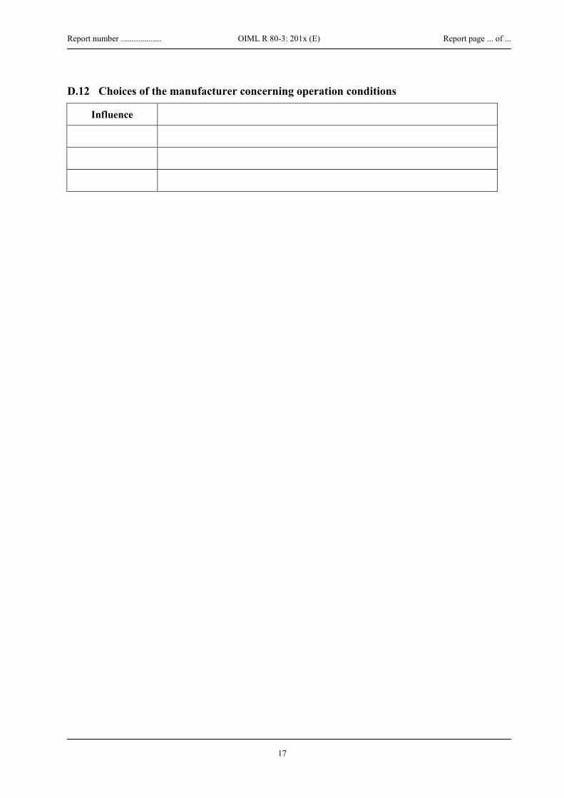
Report number ................... OIML R 80-3: 201x (E) Report page ... of ...
17
D.12 Choices of the manufacturer concerning operation conditions
Influence

Report number ................... OIML R 80-3: 201x (E) Report page ... of ...
18
E Examinations (To be completed by the Evaluating Authority) Where specified not applicable in table C.1 the underneath related tables may be removed from this report. For each of the applicable requirements an explanation on the manner in which the requirement is met is presented in the column ‘observations’.
OIML R 80-1
Sub clause
Description Yes
No
Not
app
licab
le
Observer Name: Date(s): Specimen:
Observations:
3.1 E.1 Constituents and measurement methods
3.1.2 Methods for measurement of
level by a) manual/visual gauging based on:
- single or more volumetric mark - a graduated window in the dome - another measuring device with a graduated scale - a dipstick or a dip tape
b) electronic level gauging based on:
- floats/displacers with electronic detection (magnetic or magneto-strictive);
- ultrasonic level gauge;
- radar (microwave) level gauge;
- other non-contact level gauges such as electrical capacitance
temperature a) in case transferred (delivered/received) volume
by electrical temperature sensor located on the discharge/inlet line (pipe)
b) in case : inventory measurement,
by one or more temperature sensors/thermometers located in such a way that they allow the mean temperature of the liquid volume in the tank or in each compartment to be determined,
volume at working base conditions by
a) an electronic computing device or controller
b) manual calculation using data from the tank calibration table and the volume correction table
3.1.3 Tank designed for
- delivery/receipt of full compartment only;
- delivery/receipt of partial volume of a compartment;
- automatic measurement of the average temperature of the delivered/received volume;
- automatic volume conversion.
3.1.4 Tanks fitted with ancillary devices
- installations for measuring partial volumes received or delivered;
- internal pumps;
- collectors;
- full hose installations

Report number ................... OIML R 80-3: 201x (E) Report page ... of ...
19
OIML R 80-1
Sub clause
Description Yes
No
Not
app
licab
le
Observer Name: Date(s): Specimen:
Observations:
3.1.5 Tank - at atmospheric pressure
- under pressure
- with means for heating
- with thermal insulation of containment
3.1.7 Tank mounting
- directly and permanently on the chassis of o a vehicle, trailer o a semi-articulated trailer
- self-propelled
- temporarily on the vehicle
position of the tank ensured to remain unchanged.
3.2 E.2 Construction of tanks
3.2.1 Tank with compartments
3.2.2 Tank comprised a shell and ends and discharge devices
3.2.3 Tank constructed such that it drains completely See 5.2.2.9
3.2.4 Tank discharge device comprises one or two discharge pipe(s) (allowing offloading on either side of the tanker), each equipped with a stop valve.
The flow of liquid between the tank and the discharge pipe(s) may be stopped by a foot valve. Suitable interlock to prevent the use of both discharge pipes at the same time
Devices are incorporated in the tank for water separation.
3.2.5 Tank fitted with level gauges
3.2.5.1 Incorporates an adequate dome located on top Location of level index:
Devices incorporated in the dome
- a filling aperture, fitted with a leak-proof cover;
- an orifice to observe the filling;
- a venting device or double-acting safety valve.
3.2.5.2 With mechanical level gauges
Ladder installed allowing access and performance of measurements
3.2.5.3 With electronic level gauging:
Sealing or other means prevents access
Visual checking of the interior is easily possible according to 3.2.5.2
3.2.6 No dome installed in case of tankers for liquefied gasses
3.2.7 Breather valves and flame arresters fitted where appropriate
4 E.3 Units of measurement
All applied quantity values are expressed in:
SI units: Applied units: ....
other legal units conforming OIML D2 [2007]:

Report number ................... OIML R 80-3: 201x (E) Report page ... of ...
20
OIML R 80-1
Sub clause
Description Yes
No
Not
app
licab
le
Observer Name: Date(s): Specimen:
Observations:
5.1.1. E.4 Rated operating conditions
5.1.2 E.5 Accuracy classification
Static measuring system (A)
Transportable measuring tank (B) For
- liquids of which the viscosity does not exceed 20 mPa⋅s at working temperature
(A)
(B)
- milk, beer, and other foaming liquids; - refuelling aircrafts
Class 0.5 MPE 0.5 %
0.3 %
- liquefied gases under pressure measured at a temperature equal or above –10 °C.
Class 1.0 MPE 1.0 %
0.5 %
- liquefied carbon dioxide; - liquefied gases under pressure measured at a
temperature below –10 °C Class 1.5 MPE
1.5 %
1.0 %
- cryogenic liquids. Class 2.5 MPE
2.5 %
1.5 %
5.1.5 E.6 Temperature measurement
5.1.5.1
MPE on temperature measurement
Class 0.5; 1.0; 1.5 MPEtemp
±0.5 %
Note: The maximum permissible errors apply to the indication by the corresponding calculator with its indicating device and include the errors due to rounding if using digital inputs.
Class 2.5 MPEtemp
±1.0 %
5.1.5.2 Location of temperature sensor for the measurement of a volume transferred (received or discharged)
Location
The temperature element (sensor) shall be installed in the inlet/discharge line beneath the tank at a location where under all discharge or loading modes the liquid flow passes by the sensor. In the case of separate liquid paths, additional sensor(s) shall be installed
5.1.5.4 Read out of actual temperature available
5.1.6 E.7 Nominal capacity
Nominal capacity of a measuring tank or of its compartment is at least 500 L unless stated otherwise.
5.1.7 E.8 Minimum measured quantity
5.1.7.1 The minimum measured quantity is specified for each compartment of a tank and does not exceed a quarter (1/4) of its nominal capacity.
5.1.7.2 The MMQ is equal to or greater than the volume corresponding to the level difference given below according to the accuracy class and with the smallest sensitivity or the volume which corresponds to the manufacturing tolerance on the volume and which does not exceed three-fifths of MPEA for each inclination whichever is the largest.
MMQ =
Class 0.5
1.0
1.5
2.5
Level difference 200 171 190 200 3/5 MPEA 0.3 % 0.6 % 0.9 % 1.5 % 5.1.7.3 MMQ agrees n x102 , 1 x 10n, 2 x 10n , 5 x 10n L ,( n=integer)

Report number ................... OIML R 80-3: 201x (E) Report page ... of ...
21
OIML R 80-1
Sub clause
Description Yes
No
Not
app
licab
le
Observer Name: Date(s): Specimen:
Observations:
5.2 E.9 Container of measuring tank
5.2.1 Safety and non-metrological requirements
5.2.2 General requirements on the construction of the container
5.2.2.1 Construction is sufficiently unaffected by atmospheric agents and the liquids
5.2.2.2 Container is proven tight
Class 0.5
1.0
1.5
2.5
5.2.2.3 Maximum permissible variation of the reference height H (mm) does not vary more than the greater of the two values:
2 mm or H/1000 Value: ......mm
4 mm or H/500
4 mm or H/500
4 mm or H/500
Table 2 MPEB 0.3 % 0.5 % 1.0 % 1.5 %
5.2.2.4 Maximum change in capacity of compartment between neighbouring compartments full or empty (1/3 MPEB)
0.10 % 0.17 % 0.3 % 0.5 %
5.2.2.5 Maximum change in capacity when the temperature of the tank changes ± 10 °C from the reference temperature (1/3 MPEB)
0.10 % 0.17 % 0.3 % 0.5 % Note: In any case fulfilled when the lin. expansion coefficient of the tank material < 33·10-6 K-1.
5.2.2.6 If not for liquids measured at atmospheric pressure: maximum change in capacity in the whole admissible pressure range (1/5 MPEB)
0.1 % 0.2% 0.3 % 0.5 %
5.2.2.7 Tank or compartment is such shaped that no air is trapped during the filling and no liquid is retained during the emptying in any admissible position of use of the equipment
5.2.2.8 Spouts, mouldings or vent pipes and valves are utilized in order to comply with the requirements.
5.2.2.9
Complete drainage ensured through
adequate shape of the tank
a slope of at least 2 % (1.2°) of the tank bottom with the vehicle on horizontal ground
other means : (specify how in observation column)
Monitoring/indicating facilities provided where complete drainage cannot be fully guaranteed through construction (specify how)
Table 2 MPEB 0.3 % 0.5 % 1.0 % 1.5 %
5.2.2.10 Maximum remaining volume when completely drained as part of tank capacity (1/10 MPEB)
0.03 % 0.05 % 0.1 % 0.15 %
5.2.2.11 Baffles and reinforcing elements fitted in the tank have a shape and are provided with appropriate orifices such that filling, draining and checking the emptiness of the tank is not impeded.
5.2.2.12 No objects are likely to become introduced in the tank for the purpose of adjusting the capacity to a given value, which when removed or changed and could modify the capacity of the tank
5.2.2.13 Fixed internal elements in the measuring compartments (e.g. heating coils) have
been present during the calibration and cannot be modified or dismounted.

Report number ................... OIML R 80-3: 201x (E) Report page ... of ...
22
OIML R 80-1
Sub clause
Description Yes
No
Not
app
licab
le
Observer Name: Date(s): Specimen:
Observations:
5.2.2.14 The tank or compartment geometry is such constructed that waves at the liquid
surface are adequately damped
5.2.2.15 Correct measurement is possible under all expected inclinations
The measuring tank is symmetrical in both the longitudinal as well as in the transverse direction and the level sensors is installed centrally in order to minimize inclination effects
Other construction is applied to ensure the correct volume measurement
5.2.2.16 Correct measurement is not possible under all expected inclinations, which may be during use, however the tank is equipped with a device that indicates the actual inclination with respect to the range of inclinations
5.2.2.17 The interior of the measuring tank is accessible for inspection purposes via a manhole where not excluded through safety or other regulations
5.2.2.18 The capacity of the measuring tank does not deviate by more than 10 % from that specified in the design documents
5.2.2.19 The dome, when fitted, is on the upper part of the body and is welded to the latter.
5.2.2.20 The dome has a cylinder or parallelepiped shaped geometry with vertical side-walls and the same length as the tank in case of a parallelepiped shaped dome.
Dome shape:
5.2.2.21 Orifices or cut-outs of appropriate dimensions and at high enough positions are mounted to avoid air pockets to form when filling at the maximum permitted filling level, in case the sidewalls of the dome are mounted so that they penetrate the tank shell.
5.2.2.22 The vertical cross section of the shell and dome are of symmetrical.
A different construction is applied still ensuring the correct volume measurement
5.2.2.23 The dimensions of the horizontal section of the dome is such that it allows inspection of the interior of the tank.
diameter :.... mm (at least 500 mm is recommended)

Report number ................... OIML R 80-3: 201x (E) Report page ... of ...
23
OIML R 80-1
Sub clause
Description Yes
No
Not
app
licab
le
Observer Name: Date(s): Specimen:
Observations:
5.3 E.10 Additional devices
5.3.1 Discharge device
5.3.1.1 The discharge device ensures complete and rapid discharge of the liquid contained in the tank. The discharge device is connected to the lowest part of the tank shell.
5.3.1.2 The tank is a special construction dedicated to airports and fitted with a device to collect water and impurities precipitated by a liquid contained in the tank. When the normal discharge pipe is not connected to the lowest part of the tank this device has a separate drain pipe, of small diameter and
the collective device is mounted
over the whole of the lower part of the tank
over a reduced area of the lower part.
5.3.1.3 The discharge pipe is as short as possible and has an adequate slope towards the stop valve.
Note: A resulting slope of at least 2° is recommended
5.3.1.4 Means are available for each compartment being discharged independently.
A discharge manifold is available and has suitable control facilities that prevent the flowing back from one compartment to another or provide evidence of such a situation
A discharge manifold is available and non secured manifolds are accepted because the appropriate information is easily legible and readable available close to the delivering points, which information in case where the collector is easily removable reads: “The presence of the collector is not allowed during the delivery from the measuring tank” and if the collector is not easily removable reads “Check the liquid level before and after each delivery from a compartment”
5.3.1.5 The existence of a manifold is indicated in the verification certificate. 5.3.1.6 Stop valves are readily accessible and at the rear or on the appropriate side of the
tank.
5.3.1.7 The tank consists of more than one measuring compartment and each compartment is provided with a separate (manual or automatic) shutoff device in each delivery line.
Unwanted mixtures of the products from different compartments is prevented by construction or control devices.
5.3.1.8 Where necessary, for checking emptiness in the vicinity of the lowest point of each delivery line, liquid detectors or sight glasses are installed.
5.3.1.9 Pipework, of which the filling quantity has an effect on the measurement result, is not flexible and rigidly supported.
5.3.1.10 It is ensured by a separate gas separator, or an equivalent function of existing parts, in case of full hose delivery, that the full hose is completely filled at the time of level gauging.
5.3.1.11 Control lines and control devices whose manipulation might falsify the measurement result are protected against tampering.
5.3.1.12 Filling levels are monitored in all measuring compartments if during a transaction there is a change from full to empty hose and vice versa as well as the change between the full hose systems so that manipulations are made evident.
5.3.1.13 Venting devices on the measuring system are protected against dismounting and removal as well as against manipulations from the outside.
5.3.1.14 The measuring tank has supports in the longitudinal and in the transverse directions the length of which is be greater than 500 mm in order to accommodate an electronic (spirit) level detector to mark the reference plane for the normal position of the measuring tank.
5.3.2 Installations for external measurement and pumping 5.3.2.1 It is intended to connect the tank to separate pumping or measuring device, and it
therefore is provided with an appropriate detachable coupling device that is as short as possible and can easily be connected and disconnected.

Report number ................... OIML R 80-3: 201x (E) Report page ... of ...
24
5.3.2.2 In addition to the pump itself the pumping installations comprises no more than one filter and very short pipes (no valves or branch connections) and the installation is such constructed that it can be drained completely without the need for any special measures, each time the tank is emptied.
5.3.2.3 The tank is equipped with a built-in manifold for measuring the partial volumes delivered and where a diverting valve is fitted on any discharge pipe any leakage of liquid through the diverting valve can be detected1 and the installation and the control of the diverting valves is such that the product cannot flow back from one compartment to another.
Note:1) for example: the built-in manifold ensures the complete and rapid discharge of the liquid it contains. An inspection window or monitoring device at its bottom allows for the checking of its emptiness
5.3.2.4 Sampling devices
The measuring system includes a sampling device intended to determine the properties of the liquid to be measured.
Quantity taken from the tank by the sampling device:
- Smaller than 1/3 MPEB
- Larger than 1/3 MPEB and taken into account
Class 0.5
1.0
1.5
2.5
1/3 MPEB 0.10 % 0.17 % 0.3 % 0.5 %
5.3.2.5 Additivation systems
The measuring system includes an injection device that injects additives to the delivered product.
The additivation ratio is:
- not larger than 1:500
- larger than 1:500 and the additive quantity is measured
5.3.3 Other devices
5.3.3.1 Tank is fitted with
- level switch;
- level detectors;
- high level shutoff devices;
- etc. :specify: 5.3.3.2 Devices are provided to facilitate reading of the index, or to stop the
flow automatically when the level of the liquid reaches the index not causing any additional measurement errors

Report number ................... OIML R 80-3: 201x (E) Report page ... of ...
25
OIML R 80-1
Sub clause
Description Yes
No
Not
app
licab
le
Observer Name: Date(s): Specimen:
Observations:
5.4 E.11 Level gauging system
5.4.1 General requirements
5.4.1.1 The level gauging device ensures a safe, easy and unambiguous readout, practically independent of tank tilt under rated operating conditions
5.4.1.2 The index (e.g. volumetric marks, scales), or the vertical measurement axis, are as near as possible to the center of the horizontal sections of the tank
5.4.1.3 The level gauging system will only perform and declare a height measurement valid when the liquid surface has calmed down so that the result is reproducible.
5.4.1.4 When the measuring range of the level sensor is reached, a visual and/or audible indication automatically occurs.
5.4.2 Requirements on level gauging for full compartment delivery
5.4.2.1 The shape of the tank is such that, in the zone where the levels are being gauged, a sensitivity equal to or greater than the underneath values is attained.
Sensitivity: ∆h /∆V/V:
Class 0.5
1.0
1.5
2.5
Minim. sensitivity ∆h /∆V/V [mm/ (1/1000)] 1.5 1.0 0.5 0.3
5.4.2.2 It is possible to gauge the level of the contained liquid manually in case of a non pressurized tank. The gauging device is positioned as close as possible to the curve connecting the centers of gravity of the horizontal cross sections of the compartment in the level measuring range.
- The axis of the lower end of the gauging device when close to the bottom of the tank intersects the lower tank bottom at a point having no orifice or obstacle within a radius of 100 mm.
- The axis of the lower end of the gauging device when close to the bottom of the tank does not intersect the lower tank bottom at a point having no orifice or obstacle within a radius of 100 mm but a horizontal and non removable plate of 100 mm × 100 mm is positioned in order to ensure repeatability of measurements
5.4.2.3 The reference points RPB and RPT are clearly defined and realized.
5.4.2.4 The joint between the shell and the dome aresuch that the gauging device can be held in a vertical position during measurement.
5.4.3 Requirements on level gauging for partial delivery
5.4.3.1 The expanded uncertainty of the level measurement does not exceed the underneath values
Maximum Ux =
Class 0.5
1.0
1.5
2.5
Level measurement uncertainty Ux in mm 0.7 1.2 2 3.5
The permissible ranges of product parameters will be/is specified in the type approval certificate
5.4.3.2 The resolution of the level indication is in accordance with the underneath values Level indication resolution: Class 0.5
1.0
1.5
2.5
Maximum level indication resolution [mm] 0.1 0.2 0.5 1.0
5.4.3.3 The level sensor is fitted in a damping tube to dampen the surface waves.
In the area of the tank bottom, of the tank roof and in-between, this tube is provided with openings for liquid exchange. The tube is not affect the

Report number ................... OIML R 80-3: 201x (E) Report page ... of ...
26
measurement (e.g. dirt or sedimentation occurring underregular operation).
5.4.4 Specific requirements for level gauging systems with float
5.4.4.1 The float does not change in mass or volume due to the influence of the product measured or pressure exposed to.
5.4.4.2 The cross-section of float in the range of immersion depth change is well known.
5.4.4.3 The shape of the float is such designed that it does not retain liquid except the liquid layer caused by capillary effects and no gas or air cushion is formed under the float.
5.4.4.4 Within the permissible density range of the measured liquid at base conditions, the immersion depth of the float does not change by more than the underneath given values
Class Max. change of immersion depth in mm for:
0.5
1.0
1.5
2.5
Maximum change:
- partial deliveries 0.5 0.8 1.6 2.5
- full compartment deliveries 1.5 2.4 4.8 7.5
The permissible density range is specified and is or will be registered in the type approval certificate
For measuring systems not fitted with the corresponding correction, the influence on the immersion depth that results from variation in the liquid density is included in the uncertainty evaluation of the level measurement.
5.4.5 Specific requirements for level gauging systems based on the ultrasound transit time measurements
5.4.5.1 Within the permissible product parameters range the measured height does not change by more than the underneath values Maximum change:
Class 0.5
1.0
1.5
2.5
[mm] 0.7 1.2 2 3.5
The permissible ranges of product parameters will be/is specified in the type approval certificate
5.4.5.2 The effects of the product parameters on the transit time of the ultrasound signal are compensated by suitable methods (e.g. by reference marks).

Report number ................... OIML R 80-3: 201x (E) Report page ... of ...
27
OIML R 80-1
Sub clause
Description Yes
No
Not
app
licab
le
Observer Name: Date(s): Specimen:
Observations:
5.5 E.12 Tank capacity table
5.5.1 For the conversion of the result of the level gauging into volume, the electronic data processing system stores a tank capacity table with pairs of level/volume values for each measuring compartment.
The number and distance of these value pairs are selected according to the real tank geometry
Intermediate values are calculated by suitable interpolation no extrapolation is applied
5.5.2 The tank capacity table is determined for each compartment of the measuring tank using volumetric, gravimetric or geometric methods and not merely calculated on the construction documents
5.5.3 The level range of the tank capacity table encompasses all filling states occurring in practical operation.
Filling of a measuring compartment to a level beyond the maximum permissible point of the tank capacity table is prevented for or or will be detected by the occurrence of a visual and/or audible indication.
5.5.4 Volume effects of the inclination in the range specified for a given system (pitch and roll angles) does not exceed the minimum specified volume deviation for partial delivery or the value given in the beneath table of nominal compartment volume for full compartment delivery.
Maximum volume effects of the inclination:
Class 0.5
1.0
1.5
2.5
MPEB 0.3 % 0.5 % 1.0 % 1.5 %
5.5.5 A correction for inclination should be made
Note: R 80-1 has a mistake in this
clause 5.5.5 referring to 5.1.5.2 and 5.1.5.3. The right references are 5.2.2.15 and 5.2.2.16
The inclined position of the measuring tank is measured during level detection using inclination sensors rigidly fixed to the tank.
The inclination data are utilized to correct the measurement using a suitable algorithm
5.5.6 The tank capacity table compiled during the calibration as well as the inclination correction data, when relevant, is stored in the system to prevent for manipulation.

Report number ................... OIML R 80-3: 201x (E) Report page ... of ...
28
OIML R 80-1
Sub clause
Description Yes
No
Not
app
licab
le
Observer Name: Date(s): Specimen:
Observations:
5.6 E.13 Metrological requirements for indicating and ancillary devices
5.6.1 Volume conversion
5.6.1.1 MPE for conversion = MPEA-B or (Scale interval of conversion device)/2 or Emin/2 whichever is the largest for the specific accuracy class
Class 0.5
1.0
1.5
2.5
MPE A-B = ± 0.2 % 0.5 % 0.5 % 1.0 %
(Scale interval of conversion device)/2
Emin/2
MPE for conversion =
5.6.1.2 Determining the total volume at base conditions
Method A
Partial volume #
Volume at ti
ΔVt,i = Temperature ti =
Temperature t0 =
Volume at t0
ΔV0,i
1
2
3
4
Total volume at base conditions V0 = Σ
Method B
Partial volume #
Volume at ti
ΔVt,i = Temperature ti =
Temperature ΔVt,i⋅ ti
V0 = ϕ (Vt⋅ t)
1
2
3
4
t = Σ
5.6.1.3 The utilized conversion function φ(Vt,t) is in accordance with the applicable standards (in particular, OIML R 63) , or other methods accepted for national use. Which standard ?
5.6.1.4 The temperatures of the liquid flowing through the particular delivery line during a transaction is measured in proportion to: - the volume
- the time. 5.6.1.5 Volume proportional average applied and ΔVt,i ≤Vmin/5 5.6.1.6 Time proportional average applied and the time intervals are smaller or
equal to the time needed to measure one fifth of the smallest measured quantity at maximum flow
5.6.1.7 Vt = Σ ΔVt,i= 5.6.1.9 The data underlying the conversion (for instance the density ρ0 at base
conditions or the thermal expansion coefficient α0 are protected against manipulations and - firmly set
5.6.1.10 - adjustable and value used or liquid is unambiguously indicated 5.6.1.11 No change in measuring method at verification Only one set of conversion data is entered 5.6.2 Indicating device 5.6.2.1 The reading of the indication is precise, easy and non-ambiguous. The

Report number ................... OIML R 80-3: 201x (E) Report page ... of ...
29
customer is able to inspect it without particular measures. 5.6.2.2 The resolution of the indication is in the form 1 x 10n, 2 x 10n , 5 x 10n
( n= integer or 0)
The indication is in the applicable measurement units The resolution of the indication is smaller or equal to 0.1 ⋅ Emin 5.6.2.3 Continuous display of the quantity in case of sale direct to the public 5.6.2.4 All measured and calculated values are available at an output When the volume of a product at base conditions is indicated, it is
possible to access all the values underlying the conversion.
5.6.2.5 The nature of the indicated quantity (metering or base condition) is unequivocal 5.6.2.6 The measuring system has several units for indicating the same measuring
quantity each of which satisfying all the specified requirements.
5.6.2.7 Some information, not subject to legal metrological control, is additionally indicated but clearly identified thus giving no rise to any misinterpretation
Additional information:
5.6.2.8 Where correction of a quantity value is applied the non-corrected quantity value is only available for test purposes and not displayed during normal operation
5.6.3 Price calculation is applied and a unit price can be entered. 5.6.4 Printing device 5.6.4.1 The measuring systems is applied for direct sales to the public and therefore
comprises the mandatory printing device and checks that a printer is connected (even temporarily) and ready for transactions before the delivery or receipt starts,
5.6.4.2 Data to be printed the delivery/receipt document is generated, it contains at least the following data: - an identifier for the measuring system (e.g. serial number, number
plate of the semi-trailer, or number of the compartment); - the product name or product group name; - a unique number, which increments for each transaction; - the volume Vt at working conditions with the remark “at
delivery/receipt temperature” and/or
- the volume V0 with the remark “at base conditions”. 5.6.4.3 Printing of multiple results More than one compartment is used for delivery/receipt and all the results are printed on the same delivery/receipt document More than one result is available for the same product and the results for the same product are summed up 5.6.4.4 Marking of data Verified data is enclosed by special characters (e.g. an asterisk “*”). Special Character: <SCHAR>= No non-verified data is enclosed by these special characters The delivery document contains the explanatory note:
“Data from verified devices are enclosed in <SCHAR> ..... <SCHAR>
The remark is - printed at the time the document is generated
- pre-printed on the paper being used for the printout or - on the rear side of the paper being used for the printout 5.6.5 Memory device 5.6.5.1 The measuring systems is fitted with a memory device to keep record of
commercial transactions and providing proof in the event of a dispute.
5.6.5.2 The measuring systems is not used for direct sales to the public and all data necessary for a printout is stored and not printed
5.6.5.3 The quality of the data storage means are sufficient to ensure that the stored data is not corrupted under normal storage conditions.
5.6.5.4 The data storage capability is sufficient for any particular application for which the measuring system is expected to be applied
5.6.5.5 The measured data is stored for at least the period until after finishing a transaction including the period for handling a dispute or request for reversal. If the data storage capacity is exhausted and if stored data cannot be erased because the periods specified have not yet elapsed, it is not be possible to start a new measurement.
5.6.5.6 Erasing of measured data is only possible after at least one transfer or print out of the measured data
5.6.6 Automatic stop The system allows for automatically termination of the delivery or the
loading after a set quantity value has been reached.

Report number ................... OIML R 80-3: 201x (E) Report page ... of ...
30
OIML R 80-1
Sub clause
Description Yes
No
Not
app
licab
le
Observer Name: Date(s): Specimen:
Observations:
5.7 E.14 Susceptibility for influence quantities on electronics See performance tests (F)
5.7.1.2.4 E.15 Durability
The provisions in 5.1.3 and 5.7.1.2 are met durably. No durability errors of any significance do occur, or Means assure that durability errors of any significance are acted upon
5.7.2 E.16 Power supply device
5.7.2.1 The transaction is not interrupted in case the power supply fails and the measuring system is provided with an emergency power supply device to safeguard all measuring and control functions during the failure.
5.7.2.2 The transaction is interrupted in case the power supply fails, and - the requirements of 5.7.2.1 are met, or
Note:
- the data contained at the time of the failure is saved and remains displayable on an indicating device subject to legal control for a sufficiently long time so that the current transaction can be completed
The absolute value of the
maximum permissible error for the indicated volume in this case is increased to 5 % of the MMQ
5.7.2.3 - the result of the measurement after re establishing the power supply is indicated
5.7.2.4 - the transaction is terminated properly after re establishing the power supply.
5.7.3 E.17 Checking facilities
5.7.3.1 General
5.7.3.1 A significant fault causes - an automatic correction of the change in volume
- to stop only the faulty device when the measuring system continues to comply with the regulations without this device being in operation
- the stopping of the transaction. 5.7.3.2 Function check a) by disconnecting the transducer,or
b) by interrupting one of the sensor's pulse generators, or
c) by interrupting the electrical supply of the transducer
5.7.3.3 Checking facilities for the calculator
Type I / P
It checks the values of all permanently stored instructions and data as well as all procedures for the internal transmission and storage of the data relevant to the measurement result
5.7.3.4 Checking facilities for the correctness of the calculations
Type P
Function check For example, with the aid of a parity bit, a checksum or double storage.
5.7.3.5 Checking facilities for the indicating device
Type N / I / P
Function check a failure or mal-operation of individual elements is detected
The visual check can, for example, be carried out by redundant LC segments (graphics

Report number ................... OIML R 80-3: 201x (E) Report page ... of ...
31
- visually and/or LCD) or a black-and white test.
automatically or
The automatic detection can, for example, take place by monitoring the current between the segments of LED displays or by measuring the grid voltage of fluorescent displays
cannot lead to erroneous interpretation
5.7.3.6 It is be possible to check the checking facility of the indicating device during initial verification
5.7.3.7 Checking facilities for ancillary devices Note: References 5.6.2 to 5.6.5 are unclear; this requirement concerns all ancillary devices of clause 5.6
Type N / I / P
Ensures that the particular ancillary device is available, if necessary, and that the transmission of the data is valid.
5.7.3.8 Checking facilities for printing devices
Type N / I / P
Monitors the presence of paper
6.1 E.18 Identification plate
6.1.1 Plate Available
Clearly visible, easily legible
Made of material that does not deteriorate under the rated operating conditions of the tank and allows the data to be easily inscribed.
(Provisions for installing) available
(Provisions for installing) Sealing available
Permanently attached on a support of the measuring system
6.1.2 Inscriptions
- name or trademark of the manufacturer;
- type and year of manufacture (year may be given as part of a
- serial number of the tank; serial number)
- serial number of the level gauging system, if appropriate;
- type approval number, if appropriate;
- nominal capacity of the tank or of each compartment;
- accuracy class if other than 0.5;
- minimum measured quantity of the tank or of each compartment;
- base temperature;
- range of specified inclination, if it differs from 2 %.
Free area for verification marks

Report number ................... OIML R 80-3: 201x (E) Report page ... of ...
32
OIML R 80-1
Sub clause
Description Yes
No
Not
app
licab
le
Observer Name: Date(s): Specimen:
Observations:
6.2 E.19 Measuring system document (upon initial verification)
6.2.1 Contains:
- sealing plan;
- pipework diagram;
- pneumatics diagram with the metrologically significant control lines marked;
- calibration parameter printout and calibration tables, if applicable;
- extra sheets with descriptions of changes to the measuring system, repairs as well as any breaking of official seals including their confirmations;
- signatures for the software relevant to verification and its parameters, if applicable.
6.2.2 Is kept on the tanker
6.3 E.20 Tank capacity plate (on tanks with dipsticks scaled in non-
volumetric units)
Plate Available fixed on the tank or each compartment
Inscriptions
institution which calibrated the tank and prepared the tank capacity table;
calibration certificate number;
base temperature;
number of heating coils, if appropriate;
tank capacity table (as a function of V(h) or V(C)).
6.5 E.21 Seals
6.5.1 Manipulations can be prevented and/or detected for
- indicating devices of the level gauging system;
- controller and interface units;
- terminal boxes with cables relevant to the measurements (e.g. for temperature and liquid detector);
- inclination sensors;
- temperature sensors;
- liquid detectors, except those requiring removal for cleaning;
- dipsticks on the upper and lower fastenings, where relevant;
- identification plate of the measuring system, operating instructions and pneumatic and pipework diagram, if applicable;
- dome cover and man holes of tank compartments in measuring systems which can be filled from the bottom only.
6.5.2 Heating coils, if provided, are sealed at their points of junction with the tank body.
6.5.3 The locations for seals are arranged such that the sealing and the external administrative examination is possible without hindrance. They are fixed individually for each type of measuring system within the type approval certificate.

Report number ................... OIML R 80-3: 201x (E) Report page ... of ...
33
F Performance tests F.1 Separate test of volume conversion and temperature measuring devices
OIML R 80-2 Sub. 2.3.1.1 [unit] [°C]; [K]
Test conditions Observer Name: Analogue temperature sensor
Sensor separate
Sensor including conversion device
Date: Start Stop Time: Specimen: Ambient temperature ºC ºC Ambient humidity % %
Temperature Nomimal 0 Tref = Tmax= Relative humidity [%] Quantity [unit]
reference indicated
2nd indication (if applicable) Error [unit] relative error [%] Eii MPE [%] 0,3 ; 0,6 % (3/5 of requirements of R 80-1 : 5.1.5) functional performance
Pass Fail
OIML R 80-2 Sub. 2.3.1.1 [unit] [°C]; [K]
Volume conversion device
Actual sensor Observer Name:
Simulating sensor
Date: Start Stop Time: Specimen: Ambient temperature ºC ºC Ambient humidity % %
Temperature Nomimal 0 Tref = Tmax= Relative humidity [%] Quantity [unit]
reference indicated
2nd indication (if applicable) Error [unit] relative error [%] Eii MPE [%] 0,2 ; 0,4 % (2/5 of requirements of R 80-1 : 5.1.5) functional performance
Pass Fail Observations
Result Pass Fail

Report number ................... OIML R 80-3: 201x (E) Report page ... of ...
34
F.2 Separate test of volume conversion software
OIML R 80-2 Sub. 2.3.1.2 [unit] [m3]; [L]
Test conditions Observer Name: Volume conversion
Simulated temperatures Specimen:
Date: Start Stop Time: Quantity ≥ 10 000 L
Product name: Temperature Reference Low High Quantity [unit]
calculated indicated
Error [unit] relative error [%] MPE [%] 0,05 ; 0,1 ; 0,15 ; 0,25 % functional performance
Pass Fail Product name: Temperature Reference Low High Quantity [unit]
calculated indicated
Error [unit] relative error [%] MPE [%] 0,05 ; 0,1 ; 0,15 ; 0,25 % functional performance
Pass Fail Product name: Temperature Reference Low High Quantity [unit]
calculated indicated
Error [unit] relative error [%] MPE [%] 0,05 ; 0,1 ; 0,15 ; 0,25 % functional performance
Pass Fail Observations
Result Pass Fail
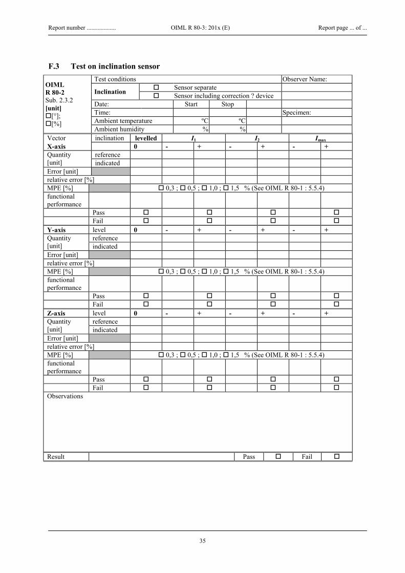
Report number ................... OIML R 80-3: 201x (E) Report page ... of ...
35
F.3 Test on inclination sensor
OIML R 80-2 Sub. 2.3.2 [unit] [°]; [%]
Test conditions Observer Name:
Inclination Sensor separate Sensor including correction ? device
Date: Start Stop Time: Specimen: Ambient temperature ºC ºC Ambient humidity % %
Vector inclination levelled I1 I2 Imax X-axis 0 - + - + - + Quantity [unit]
reference indicated
Error [unit] relative error [%] MPE [%] 0,3 ; 0,5 ; 1,0 ; 1,5 % (See OIML R 80-1 : 5.5.4) functional performance
Pass Fail Y-axis level 0 - + - + - + Quantity [unit]
reference indicated
Error [unit] relative error [%] MPE [%] 0,3 ; 0,5 ; 1,0 ; 1,5 % (See OIML R 80-1 : 5.5.4) functional performance
Pass Fail Z-axis level 0 - + - + - + Quantity [unit]
reference indicated
Error [unit] relative error [%] MPE [%] 0,3 ; 0,5 ; 1,0 ; 1,5 % (See OIML R 80-1 : 5.5.4) functional performance
Pass Fail Observations
Result Pass Fail

Report number ................... OIML R 80-3: 201x (E) Report page ... of ...
36
F.4 Separate test on floats (general)
OIML R 80-2 Sub. 2.3.3.1 [unit] [mm]; [cm]; [m];
Test conditions Observer Name: (separate table for each type of float) Date: Start Stop Specimen: Time: Ambient temperature ºC ºC Mass of float: [g] Ambient humidity % % Volume: [cm3] No Yes R 80-2 Sub Min. perm D Reference Float 2.3.3.1.4 Max. perm D Float marked 2.3.3.1.5
Float type: Liquid Type Close to min. density Close to max. density deviation Liquid density Immersion dept [unit] ( =Quantity)
reference calculated indicated
Error [unit] Difference: Documentation reference Spec´s Min. permissible D Max. permissible D Specified Calculated (using error) relative error [%] MPE [%] Table 8 of R 80-1
Documentation Adequate Pass Inadequate Fail
Resistance R 80-2
Chemical Sub. 2.3.3.2.1
Previously proven adequate Pass Proven adequate through testing Pass Not proven adequate Fail
Pressure Sub. 2.3.3.2.2
Proven to withstand 1.5 times overpressure Pass Not proven to withstand 1.5 times overpressure Fail
Adaption of float to rod R 80-2 Sub. 2.3.3.2.3
Adequate (not stuck at maximum inclination) Pass Inadequate Fail
Temperature influence on immersion depth
The immersion depth of the float does not change by more than the values given in Table 8 of R 80-1
Pass Fail Observations
Result Pass Fail

Report number ................... OIML R 80-3: 201x (E) Report page ... of ...
37
F.5 Separate test of dipstick pipes for ultrasonic systems
OIML R 80-2 Sub. 2.3.4 [unit] [mm]; [cm]; [m]
Test conditions Observer Name: (separate table for each type ultrasound level) Date: Start Stop Specimen: Time: Ambient temperature ºC ºC Ambient humidity % %
Float type: Level # 1 2 3 Level = Tref = + .. °C Liquid Type: Water Quantity [unit]
reference indicated
Error [unit] relative error [%] E MPE [%] Permissible deviations do not exceed the values given in Table 4 of
R 80-1 functional performance
Pass Fail Observations
Result Pass Fail

Report number ................... OIML R 80-3: 201x (E) Report page ... of ...
38
F.6.1 Static temperature tests (influence of dry heat)
OIML R 80-2 Sub. 3.4.1 [unit] [mm]; [cm]; [m]
Test conditions Observer Name:
Level Actual level Simulating level
Date: Start Stop Time: Specimen: Ambient temperature ºC ºC Ambient humidity % %
Tnom = +20 °C Level # 1 2 3 = Reference: Level = Absolute humidity [g/m3] Relative humidity [%] Quantity [unit]
reference indicated
2nd indication (if applicable) Error [unit] relative error [%] Eii MPE [%] 0,5 ; 1,0 ; 1,5 ; 2,5 % functional performance
Pass Fail Tah = +55 ºC Level # 1 2 3 High limit Level = Absolute humidity [g/m3] Quantity [unit]
reference indicated
2nd indication (if applicable) Error [unit] relative error [%] Ei MPE [%] 0,5 ; 1,0 ; 1,5 ; 2,5 % functional performance
Pass Fail Tnom = +20°C Level # 1 2 3 = Reference: Level = Absolute humidity [g/m3] Relative humidity [%] Quantity [unit]
reference indicated
2nd indication (if applicable) Error [unit] relative error [%] Ei MPE [%] 0,5 ; 1,0 ; 1,5 ; 2,5 % functional performance
Pass Fail Observations
Result Pass Fail

Report number ................... OIML R 80-3: 201x (E) Report page ... of ...
39
F.6.2 Static temperature test (influence of cold)
OIML R 80-2 Sub. 3.4.2 [unit] [mm]; [cm]; [m]
Test conditions Observer Name:
Level Actual level Simulating level
Date: Start Stop Time: Specimen: Ambient temperature ºC ºC Initial pressure
Tnom = +20 °C Level # 1 2 3 = Reference: Level = Absolute humidity [g/m3] Quantity [unit]
reference indicated
2nd indication (if applicable) Error [unit] relative error [%] Eii MPE [%] 0,5 ; 1,0 ; 1,5 ; 2,5 % functional performance
Pass Fail Tal = -25 ºC Level # 1 2 3 Low limit Level = Quantity [unit]
reference indicated
2nd indication (if applicable) Error [unit] relative error [%] Ei MPE [%] 0,5 ; 1,0 ; 1,5 ; 2,5 % functional performance
Pass Fail Tnom = +20 °C Level # 1 2 3 = Reference: Level = Absolute humidity [g/m3] Quantity [unit]
reference indicated
2nd indication (if applicable) Error [unit] relative error [%] Ei MPE [%] 0,5 ; 1,0 ; 1,5 ; 2,5 % functional performance
Pass Fail Observations
Result Pass Fail

Report number ................... OIML R 80-3: 201x (E) Report page ... of ...
40
F.6.3 Damp heat, cyclic (condensing)
OIML R 80-2 Sub.3.4.3 [unit] [mm]; [cm]; [m]
Test conditions Observer Name:
Level Actual level Simulating level
Start Stop Specimen: Date: Tah = 55 ºC Time: Tal = 25 ºC
First cycle Cycle phase initial rise to Tah stabilize Level = Test temperature
start [ºC] stop [ºC]
Relative humidity
start [%] stop [%]
Time Start h tb = h h Stop (ts ) h = tb h h
Required: ts = tb + 3 h tb + 12 h Quantity [unit]
reference indicated
2nd indication (if applicable) Error [unit] relative error [%] Eii MPE [%] 0,5 ; 1,0 ; 1,5 ; 2,5 % Pass Fail Cycle phase Lowering to Tal stabilize after Level = Test temperature
start [ºC] stop [ºC]
Relative humidity
start [%] stop [%]
Time Start h h h Stop (ts ) h h h
Required: ts = tb + (15 ÷18 h) tb + 24 h Quantity [unit]
reference indicated
2nd indication (if applicable) Error [unit] relative error [%] Eii MPE [%] 0,5 ; 1,0 ; 1,5 ; 2,5 % Fault limit [%] 0.2·MPE or Emin (whichever is the largest Acts on fault Yes No Significant fault Yes No Observations
Result Pass Fail

Report number ................... OIML R 80-3: 201x (E) Report page ... of ...
41
F.6.4 Vibration (random)
R 80-2 Sub.3.4.4 [unit] [mm]; [cm]; [m]
Test conditions Observer Name:
Level Actual level Simulating level
Date: Start Stop Time: Specimen: Ambient temperature ºC ºC Frequency 10-150 Hz Relative humidity % % Total RMS level 7 m/s2
Vector Before test
During test
After test
During test
After test
During test
After test
X-axis level Quantity [unit]
reference indicated
Error [unit] relative error [%] Eii Ei Ei Ei MPE [%] 0,5 ; 1,0 ; 1,5 ; 2,5 % functional performance
Pass Fail Y-axis level Quantity [unit]
reference indicated
Error [unit] relative error [%] Eii Ei Ei Ei MPE [%] 0,5 ; 1,0 ; 1,5 ; 2,5 % functional performance
Pass Fail Z-axis level Quantity [unit]
reference indicated
Error [unit] relative error [%] Eii Ei Ei Ei MPE [%] 0,5 ; 1,0 ; 1,5 ; 2,5 % functional performance
Pass Fail Observations
Result Pass Fail

Report number ................... OIML R 80-3: 201x (E) Report page ... of ...
42
F.7.1 RF immunity (radiated electromagnetic fields)
OIML R 80-2 Sub.3.4.5 [unit] [mm]; [cm]; [m]
Test conditions Observer Name:
Level Actual level Simulating level Specimen:
Field strength 10 V/m Date: Start Stop Dwell time s Time: Ambient temperature ºC ºC fl = MHz Fluid temperature ºC ºC fh = MHz Relative humidity % %
Phase Initial During exposure After Level =
Quantity [unit]
reference indicated
2nd indication (if applicable) Error [unit] relative error [%] Eii MPE [%] 0,5 ; 1,0 ; 1,5 ; 2,5 % Pass Fail Observed faults during exposure
Fault limit [%] 0.2·MPE or Emin (whichever is the largest) Frequency Fault/Deviation Significant Acts on fault MHz Yes No Yes No Observations
Result Pass Fail

Report number ................... OIML R 80-3: 201x (E) Report page ... of ...
43
F.7.2 RF immunity (common mode currents generated by radio frequency electromagnetic fields)
OIML R 80-2 Sub.3.4.6 [unit] [mm]; [cm]; [m]
Test conditions RF current injection Observer Name:
Level Actual level Simulating level Specimen:
RF voltage 10 Ve.m.f. Date: Start Stop Dwell time s Time: Ambient temperature ºC ºC fl = MHz Relative humidity % % fh = MHz
Phase Initial During exposure After Level =
Quantity [unit]
reference indicated
2nd indication (if applicable) Error [unit] relative error [%] Eii MPE [%] 0,5 ; 1,0 ; 1,5 ; 2,5 % Pass Fail Observed faults during exposure
Fault limit [%] 0.2·MPE or Emin (whichever is the largest) Frequency Cable exposed Fault/Deviation Significant Acts on fault MHz Yes No Yes No Observations
Result Pass Fail

Report number ................... OIML R 80-3: 201x (E) Report page ... of ...
44
F.7.3 Immunity to electrostatic discharges
OIML R 80-2 Sub.3.4.7 [unit] [mm]; [cm]; [m]
Test conditions Observer Name:
Level Actual level Simulating level Specimen:
Date: Start Stop # discharges : Time: Note: at least 10 Ambient temperature ºC ºC contact 6 kV Relative humidity % % air 8 kV
Phase Initial During exposure After Level = Quantity [unit]
reference indicated
2nd indication (if applicable) Error [unit] relative error [%] Eii MPE [%] 0,5 ; 1,0 ; 1,5 ; 2,5 % Pass Fail Observed faults during exposure
Fault limit [%] 0.2·MPE or Emin (whichever is the largest) Exposed surface
Discharge type Fault/ Deviation
Significant Acts on fault
Air Contact Level Yes No Yes No Observations
Result Pass Fail

Report number ................... OIML R 80-3: 201x (E) Report page ... of ...
45
F.7.4 Immunity to power frequency magnetic fields
OIML R 80-2 Sub.3.4.8 [unit] [mm]; [cm]; [m]
Test conditions Observer Name:
Level Actual level Simulating level Specimen:
Fieldstrength A/m Date: Start Stop Dwell time s Time: Ambient temperature ºC ºC fl = 50/60 Hz Relative humidity % %
Phase Initial During exposure After Level =
Quantity [unit]
reference indicated
2nd indication (if applicable) Error [unit] relative error [%] Eii MPE [%] 0,5 ; 1,0 ; 1,5 ; 2,5 % Pass Fail Observed faults during exposure
Fault limit [%] 0.2·MPE or Emin (whichever is the largest) Fault/Deviation Significant Acts on fault Exposure Fieldstrength Yes No Yes No Continuous 30 A/m Short (1-3 s) 300 A/m Observations
Result Pass Fail

Report number ................... OIML R 80-3: 201x (E) Report page ... of ...
46
F.7.5 Bursts on signal data and control lines
OIML R 80-2 Sub.3.4.9 [unit] [mm]; [cm]; [m]
Test conditions Observer Name:
Level Actual level Simulating level Specimen:
Date: Start Stop Level 1 kV Time: Ambient temperature ºC ºC Repetition: 5 kHz Relative humidity % %
Phase Initial During exposure After Level = Quantity [unit]
reference indicated
2nd indication (if applicable) Error [unit] relative error [%] Eii MPE [%] 0,5 ; 1,0 ; 1,5 ; 2,5 % Pass Fail Observed faults during exposure Fault limit [%] 0.2·MPE or Emin (whichever is the largest) Fault/Deviation Significant Acts on fault
Line Pol. Yes No Yes No Port 1(*) ↑
↓ Port 2(*) ↑
↓ Port 3(*) ↑
↓ Port 4(*) ↑
↓ (*) Description of the Ports:
Port 1:
Port 2:
Port 3:
Port 4:
Observations
Result Pass Fail

Report number ................... OIML R 80-3: 201x (E) Report page ... of ...
47
F.7.6 Influence of AC mains voltage variations
OIML R 80-2 Sub.3.4.10 [unit] [mm]; [cm]; [m]
Test conditions Observer Name:
Level Actual level Simulating level Specimen:
Date: Start Stop Time: Nominal = Unom = (Unom1 +Unom2)/2 Ambient temperature ºC ºC High = Unom1 + 10 % Relative humidity % % Low = Unom2 - 15 %
Reference: Voltage Nominal High Nominal Low Nominal Level = Quantity [unit]
Reference Indicated
Error [unit] relative error [%] MPE [%] 0,5 ; 1,0 ; 1,5 ; 2,5 % functional performance
Pass Fail Observations
Result Pass Fail

Report number ................... OIML R 80-3: 201x (E) Report page ... of ...
48
F.7.7 Immunity to surges on AC mains power lines
OIML R 80-2 Sub.3.4.11 [unit] [mm]; [cm]; [m]
Test conditions Observer Name:
Level Actual level Simulating level
Date: Start Stop Specimen: Time: Ambient temperature ºC ºC Line to line 1 kV Relative humidity % % Line to earth 2 kV
Phase Initial During exposure After Level = Quantity [unit]
Reference Indicated
2nd indication (if applicable) Error [unit] relative error [%] Eii MPE [%] 0,5 ; 1,0 ; 1,5 ; 2,5 % Pass Fail Observed faults after exposure Fault limit [%] 0.2*MPE or Emin (whichever is the largest) Phase angle Fault/Deviation Significant Acts on fault
0° 90° 180° 270° Yes No Yes No Line to line
3x↑ 3x ↑ 3x ↑ 3x ↑
3x ↓ 3x ↓ 3x ↓ 3x ↓
Line to earth 3x↑
3x ↑ 3x ↑ 3x ↑
3x ↓ 3x ↓ 3x ↓ 3x ↓
Observations
Result Pass Fail

Report number ................... OIML R 80-3: 201x (E) Report page ... of ...
49
F.7.8 Immunity to AC mains voltage dips and short interruptions
OIML R 80-2 Sub.3.4.12 [unit] [mm]; [cm]; [m]
Test conditions Observer Name:
Level Actual level Simulating level
Date: Start Stop Specimen: Time: Repetition: 10 times Ambient temperature ºC ºC Intervals: 10 s Fluid temperature ºC ºC Relative humidity % %
Phase Initial During exposure After Level = Quantity [unit]
Reference Indicated
2nd indication (if applicable) Error [unit] relative error [%] Eii MPE [%] 0,5 ; 1,0 ; 1,5 ; 2,5 % Pass Fail Observed faults during exposure Fault limit [%] 0.2·MPE or Emin (whichever is the largest) Reduction to [ % Unom]
Duration [cycles]
Fault/Deviation Significant Acts on fault
Yes No Yes No 0 0.5 0 1
40 10 / 12 70 25 / 30 80 250 / 300 0 250 / 300
Observations
Result Pass Fail

Report number ................... OIML R 80-3: 201x (E) Report page ... of ...
50
F.7.9 Immunity to bursts on AC mains power lines
OIML R 80-2 Sub.3.4.13 [unit] [mm]; [cm]; [m]
Test conditions Observer Name:
Level Simulating Level Specimen:
Cable: Date: Start Stop Time: Level 2 kV Ambient temperature ºC ºC Repetition: 5 kHz Relative humidity % %
Phase Initial During exposure After Level = Quantity [unit]
reference indicated
2nd indication (if applicable) Error [unit] relative error [%] Eii MPE [%] 0,5 ; 1,0 ; 1,5 ; 2,5 % Pass Fail Observed faults during exposure Fault limit [%] 0.2·MPE or Emin (whichever is the largest) Fault/Deviation Significant Acts on fault
Line Pol. Yes No Yes No phase ↑
↓ neutral ↑
↓ Protective
earth ↑ ↓
Port 1(*) ↑ ↓
Port 2(*) ↑ ↓
Port 3(*) ↑ ↓
Port 4(*) ↑ ↓
(*) Description of the Ports:
Port 1:
Port 2:
Port 3:
Port 4:
Observations
Result Pass Fail

Report number ................... OIML R 80-3: 201x (E) Report page ... of ...
51
F.7.10 Influence of low voltage of internal battery
OIML R 80-2 Sub.3.4.14 [unit] [mm]; [cm]; [m]
Test conditions Observer Name:
Level Actual level Simulating level
Date: Start Stop Time: Specimen: Ambient temperature ºC ºC Relative humidity % %
Reference: Voltage Nominal Ubmin 0.9Ubmin Nominal Ubmin 0.9Ubmin Level Quantity [unit]
Reference Indicated
Error [unit] relative error [%] MPE [%] 0,5 ; 1,0 ; 1,5 ; 2,5 % functional performance
Pass Fail Observations
Result Pass Fail

Report number ................... OIML R 80-3: 201x (E) Report page ... of ...
52
F.7.11 Influence of vehicle battery voltage variations
OIML R 80-2 Sub.3.4.15.1 [unit] [mm]; [cm]; [m]
Test conditions Observer Name:
Level Actual level Simulating level Specimen:
Date: Start Stop Battery voltage Time: Nominal 12 V 24 V Ambient temperature ºC ºC High 16 V 32 V Relative humidity % % Low 9 V 16 V
Reference: Voltage Nominal High Nominal Low Nominal Level Quantity [unit]
reference indicated
Error [unit] relative error [%] MPE [%] 0,5 ; 1,0 ; 1,5 ; 2,5 % functional performance
Pass Fail Observations
Result Pass Fail

Report number ................... OIML R 80-3: 201x (E) Report page ... of ...
53
F.7.12 Immunity to electrical transients along supply lines
OIML R 80-2 Sub.3.4.15.2 [unit] [mm]; [cm]; [m]
Test conditions Observer Name:
Level Actual level Simulating level Repetition: times
Date: Start Stop Specimen: Time: Nom. battery
voltage 12 V
Ambient temperature ºC ºC 24 V Relative humidity % %
Phase Initial During exposure After Level = Quantity [unit]
reference indicated
2nd indication (if applicable) Error [unit] relative error [%] Eii MPE [%] 0,5 ; 1,0 ; 1,5 ; 2,5 % Pass Fail Observed faults during exposure Fault limit [%] 0.2·MPE or Emin (whichever is the largest) Nominal 12 V 24 V Fault/Deviation Significant Acts on fault
Test pulse Pulse voltage Us [V]
Yes No Yes No
2a +50 +50 2b +10 +20 3a -150 -200 3b +100 +200
Observations
Result Pass Fail

Report number ................... OIML R 80-3: 201x (E) Report page ... of ...
54
F.7.13 Immunity to electrical transients along other than supply lines
OIML R 80-2 Sub.3.4.15.3 [unit] [mm]; [cm]; [m]
Test conditions Observer Name:
Level Actual level Simulating level Repetition: times
Date: Start Stop Specimen: Time: Nom. battery
voltage 12 V
Ambient temperature ºC ºC 24 V Relative humidity % %
Phase Initial During exposure After Level = Quantity [unit]
reference indicated
2nd indication (if applicable) Error [unit] relative error [%] Eii MPE [%] 0,5 ; 1,0 ; 1,5 ; 2,5 % Pass Fail Observed faults during exposure Fault limit [%] 0.2·MPE or Emin (whichever is the largest) Nominal 12 V 24 V Fault/Deviation Significant Acts on fault
Test pulse Pulse voltage Us [V]
Yes No Yes No
a -60 -80 b +40 +80
Observations
Result Pass Fail