common reasons for o-ring failure compression set compression set failure pattern: common to both...
TRANSCRIPT
83
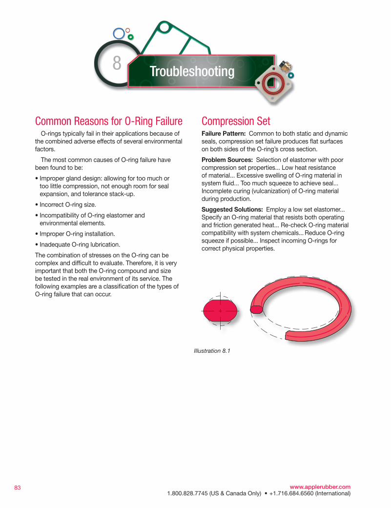
Compression SetFailure Pattern: Common to both static and dynamic seals, compression set failure produces flat surfaces on both sides of the O-ring’s cross section.
Problem Sources: Selection of elastomer with poor compression set properties... Low heat resistance of material... Excessive swelling of O-ring material in system fluid... Too much squeeze to achieve seal... Incomplete curing (vulcanization) of O-ring material during production.
Suggested Solutions: Employ a low set elastomer...Specify an O-ring material that resists both operating and friction generated heat... Re-check O-ring material compatibility with system chemicals... Reduce O-ring squeeze if possible... Inspect incoming O-rings for correct physical properties.
Common Reasons for O-Ring Failure O-rings typically fail in their applications because of the combined adverse effects of several environmental factors.
The most common causes of O-ring failure have been found to be:
• Improper gland design: allowing for too much or too little compression, not enough room for seal expansion, and tolerance stack-up.
• Incorrect O-ring size.
• Incompatibility of O-ring elastomer and environmental elements.
• Improper O-ring installation.
• Inadequate O-ring lubrication.
The combination of stresses on the O-ring can be complex and difficult to evaluate. Therefore, it is very important that both the O-ring compound and size be tested in the real environment of its service. The following examples are a classification of the types of O-ring failure that can occur.
Troubleshooting8
Illustration 8.1
www.applerubber.com 1.800.828.7745 (US & Canada Only) • +1.716.684.6560 (International)
84
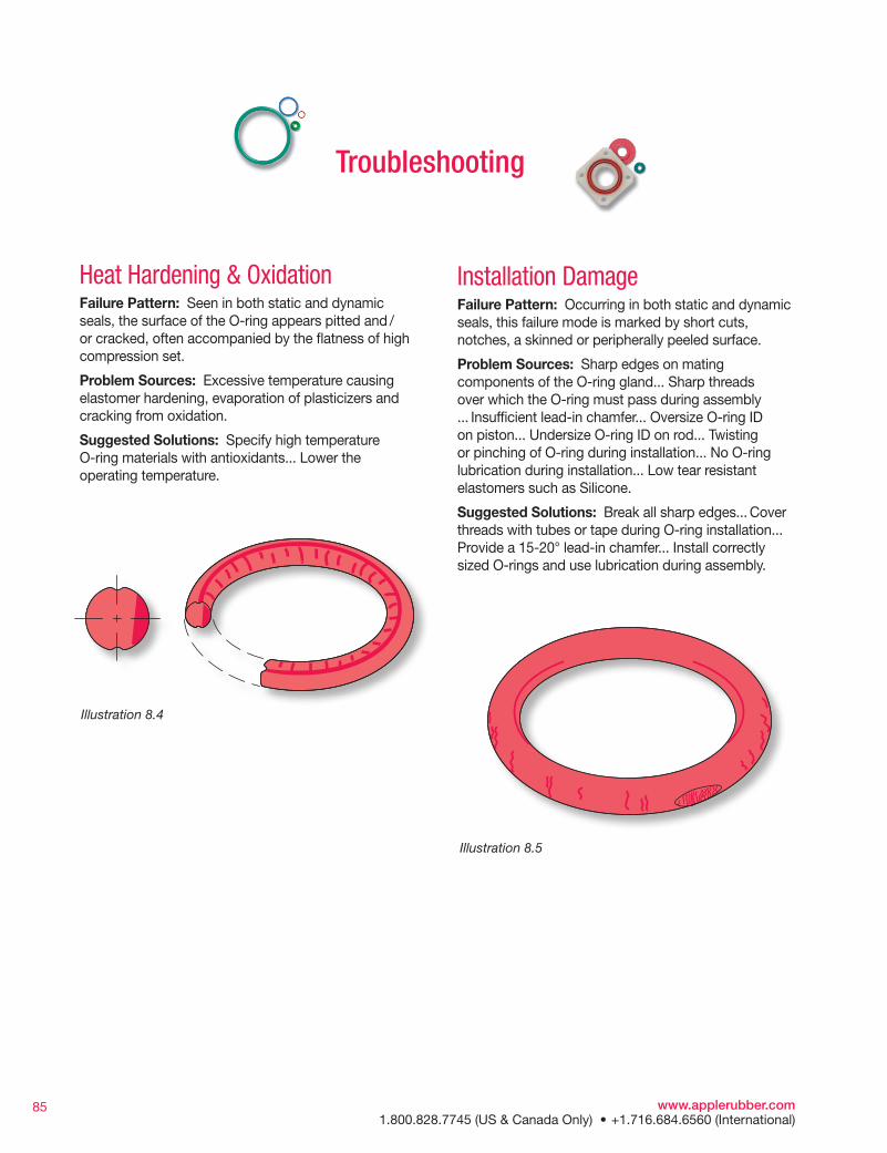
AbrasionFailure Pattern: Occurring primarily in dynamic seals involving reciprocating, oscillating, or rotary motion, this failure pattern can be identified by a flattened surface on one side of the O-ring’s cross section.
Problem Sources: Metal surfaces too rough(acting as an abrasive)... Metal surfaces too smooth causing inadequate lubrication... Poor lubrication ... Excessive temperatures... System contaminated with abrasives.
Suggested Solutions: Use recommended metal finishes...Provide adequate lubrication (consider internally-lubed O-rings)... Check material compatibility with system temperature... Eliminate abrasive contamination with filters and/or wiper seals ... Consider change to a more abrasive resistant O-ring material such as carboxilated nitrile or urethane (see Section 5, Material Selection Guide).
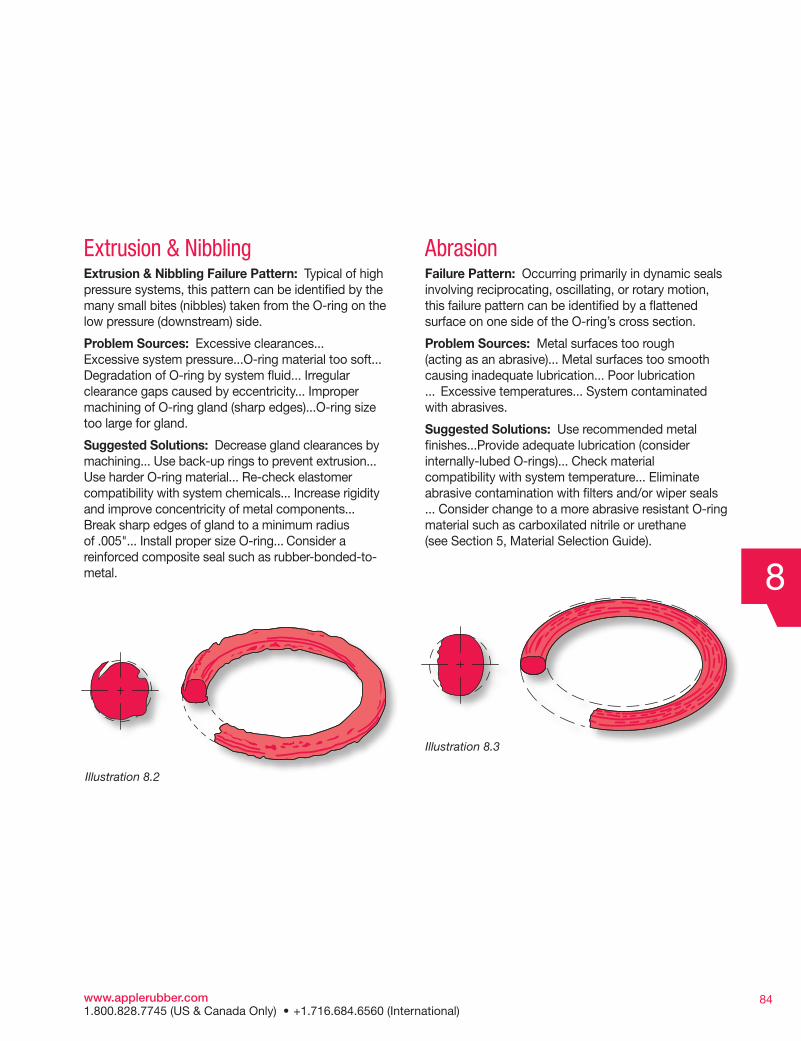
Extrusion & Nibbling Extrusion & Nibbling Failure Pattern: Typical of high pressure systems, this pattern can be identified by the many small bites (nibbles) taken from the O-ring on the low pressure (downstream) side.
Problem Sources: Excessive clearances... Excessive system pressure...O-ring material too soft... Degradation of O-ring by system fluid... Irregular clearance gaps caused by eccentricity... Improper machining of O-ring gland (sharp edges)...O-ring size too large for gland.
Suggested Solutions: Decrease gland clearances by machining... Use back-up rings to prevent extrusion... Use harder O-ring material... Re-check elastomer compatibility with system chemicals... Increase rigidity and improve concentricity of metal components... Break sharp edges of gland to a minimum radius of .005"... Install proper size O-ring... Consider a reinforced composite seal such as rubber-bonded-to-metal. 8
Illustration 8.2
Illustration 8.3
www.applerubber.com 1.800.828.7745 (US & Canada Only) • +1.716.684.6560 (International)
85
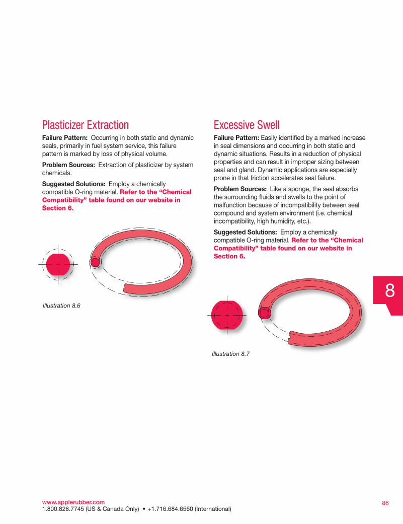
Heat Hardening & OxidationFailure Pattern: Seen in both static and dynamic seals, the surface of the O-ring appears pitted and /or cracked, often accompanied by the flatness of high compression set.
Problem Sources: Excessive temperature causing elastomer hardening, evaporation of plasticizers and cracking from oxidation.
Suggested Solutions: Specify high temperatureO-ring materials with antioxidants... Lower the operating temperature.
Installation DamageFailure Pattern: Occurring in both static and dynamic seals, this failure mode is marked by short cuts, notches, a skinned or peripherally peeled surface.
Problem Sources: Sharp edges on mating components of the O-ring gland... Sharp threads over which the O-ring must pass during assembly ... Insufficient lead-in chamfer... Oversize O-ring ID on piston... Undersize O-ring ID on rod... Twisting or pinching of O-ring during installation... No O-ring lubrication during installation... Low tear resistant elastomers such as Silicone.
Suggested Solutions: Break all sharp edges... Cover threads with tubes or tape during O-ring installation...Provide a 15-20° lead-in chamfer... Install correctly sized O-rings and use lubrication during assembly.
Troubleshooting
Illustration 8.4
Illustration 8.5
www.applerubber.com 1.800.828.7745 (US & Canada Only) • +1.716.684.6560 (International)
86
Plasticizer ExtractionFailure Pattern: Occurring in both static and dynamic seals, primarily in fuel system service, this failure pattern is marked by loss of physical volume.
Problem Sources: Extraction of plasticizer by system chemicals.
Suggested Solutions: Employ a chemically compatible O-ring material. Refer to the “Chemical Compatibility” table found on our website in Section 6.
Excessive Swell Failure Pattern: Easily identified by a marked increase in seal dimensions and occurring in both static and dynamic situations. Results in a reduction of physical properties and can result in improper sizing between seal and gland. Dynamic applications are especially prone in that friction accelerates seal failure.
Problem Sources: Like a sponge, the seal absorbs the surrounding fluids and swells to the point of malfunction because of incompatibility between seal compound and system environment (i.e. chemical incompatibility, high humidity, etc.).
Suggested Solutions: Employ a chemically compatible O-ring material. Refer to the “Chemical Compatibility” table found on our website in Section 6.
8Illustration 8.6
Illustration 8.7
www.applerubber.com 1.800.828.7745 (US & Canada Only) • +1.716.684.6560 (International)

87
Spiral FailureFailure Pattern: Generally found on long stroke, hydraulic piston seals, the surface of the O-ring exhibits a series of deep, spiral 45 degree angle cuts.
Problem Sources: Caused when some segmentsof the O-ring slide while other segments simultaneously roll. At a single point on its periphery, the O-ring gets caught on an eccentric component, or against the cylinder wall, causing twisting and development of 45 degree angle, surface cuts.
Contributing Conditions Include: Eccentric components... Wide clearance combined with side loads... Uneven surface finishes... Inadequate lubrication... Excessive O-ring material softness... Too slow stroke speeds.
Suggested Solutions: Check for out-of-round cylinder bore... Decrease clearance gap... Machine metal surfaces to 10-20 micro-inch finish... Improve lubrication (consider internally-lubed O-rings)... Increase O-ring material hardness and/or cross section... Employ anti-extrusion back-up rings.
Weather or Ozone CrackingFailure Pattern: Occurring in both static and dynamic seals exposed to atmospheres containing ozone and other air pollutants, this failure mode is marked by the appearance of many small surface cracks perpendicular to the direction of stress.
Problem Sources: Ozone attack of the polymer chains causing O-ring cracking.
Suggested Solutions: Employ O-ring elastomers that are resistant to ozone attack. See Section 6, “General Properties Of O-Ring Elastomers”.
Troubleshooting
Illustration 8.8
Illustration 8.9
www.applerubber.com 1.800.828.7745 (US & Canada Only) • +1.716.684.6560 (International)
88
Failure Without Visible Evidence on SealFailure Pattern: Of the various types of seal failure, this is among the hardest to diagnose because the result of the problem is not visible on the O-ring.
Problem Sources: Lack of compression... Tolerance stack-up...Eccentric components...Parting lines/flash... Improper seal/gland volume relationship.
Suggested Solutions: Maintain recommended compression range for the application... Identify the amount of stretch as it reduces the O-ring cross section with increased stretch... Determine the component tolerance stack-up as it directly affects the seal cross section... Consider maximum component shift in design to ensure that compression is still contained within recommended compression range... Avoid parting lines in O-ring grooves as they tend to be areas of flash and mismatch... Ensure that the O-ring gland volume surpasses the O-ring volume to allow for seal expansion without seal detriment.
Other ProblemsIf you have been unable to diagnose your current problem within the guidelines provided in the preceding pages, please refer to the EAR (Engineering Assistance Request) form on Apple Rubber’s Website at www.applerubber.com, which enables you to send your request via the Internet. We will be glad to share our many years of seal experience with you.
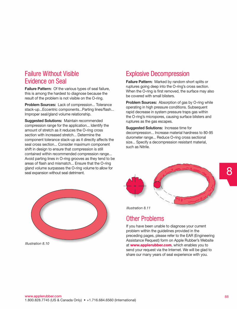
Explosive DecompressionFailure Pattern: Marked by random short splits or ruptures going deep into the O-ring’s cross section. When the O-ring is first removed, the surface may also be covered with small blisters.
Problem Sources: Absorption of gas by O-ring while operating in high pressure conditions. Subsequent rapid decrease in system pressure traps gas within the O-ring’s micropores, causing surface blisters and ruptures as the gas escapes.
Suggested Solutions: Increase time for decompression... Increase material hardness to 80-95 durometer range... Reduce O-ring cross sectional size... Specify a decompression resistant material, such as Nitrile.
8
Illustration 8.10
Illustration 8.11
www.applerubber.com 1.800.828.7745 (US & Canada Only) • +1.716.684.6560 (International)