© commonwealth of australia 2015 -...
TRANSCRIPT

© Commonwealth of Australia 2015
CPCPCM2050A – MARK OUT MATERIALS
© Australian National Training Authority 2004 – Version 1
ii
CONSTRUCTION, PLUMBING AND SERVICE
INTEGRATED FRAMEWORK
TRAINING PACKAGE
CPC08
CPCPCM2050A
MARK OUT MATERIALS
LEARNING GUIDE

CPCPCM2050A - MARK OUT MATERIALS
© Commonwealth of Australia 2015
ACKNOWLEDGEMENTS
National Plumbing Services Training Advisory Group
Plumbing Industry Commission Victoria
© Commonwealth of Australia 2015
Construction and Property Services Industry Skills Council PO Box 151 Belconnen ACT 2616 Tel: 02 6253 0002 www.cpsisc.com.au This work is copyright, but permission is given to trainers and teachers to make copies and contextualise the resources for use within their own training organisation or in a workplace where training is being conducted. This permission does not extend to making copies for use outside the immediate training environment for which they are made, or the making of copies for hire or resale to third parties.
This work was first published in 2004 with the assistance of funding provided by the Commonwealth Government through the Australian National Training Authority (ANTA). The 2015 publication has been updated to reflect changes to the national units of competency.
The views expressed in this work do not necessarily represent the views of the Commonwealth of Australia or CPSISC. In addition, the Commonwealth of Australia and CPSISC do not give warranty or accept any legal liability in relation to the content of this work.
The website addresses and other contact information provided in this publication were compiled in good faith and were correct at the time of printing. The updating of these resources was completed by:
National Plumbing and Services Training Advisory Group, with funding and support provided by the Construction and Property Services Industry Skills Council (CPSISC):
This guide was developed in consultation with representatives of the Plumbing Industry by NPSTAG and CPSISC to support the implementation of the CPC08 Construction, Plumbing and Services Training Package.

CPCPCM2050A – MARK OUT MATERIALS
ii © Commonwealth of Australia 2015
Contents
What is this resource about? ................................................................................................ 1
How do I use this resource? ................................................................................................. 1
Flexible Delivery ................................................................................................................. 1
What do I have to do? .......................................................................................................... 1
Mark out materials ............................................................................................................... 2
Unit Descriptor .................................................................................................................... 2
Element ................................................................................................................................ 2
Performance Criteria ........................................................................................................... 2
Required knowledge ............................................................................................................ 4
How will I be assessed? ....................................................................................................... 4
Are there any prerequisites? ................................................................................................ 4
What other resources will I need? ....................................................................................... 5
Web sites ............................................................................................................................. 5
Video or audio cassettes ...................................................................................................... 5
Introduction ......................................................................................................................... 6
Standards, codes and symbols ............................................................................................. 6
Codes ................................................................................................................................... 6
Prepare for work .................................................................................................................. 6
WHS Requirements ............................................................................................................. 7
Quality assurance ................................................................................................................. 7
Prepared work area .............................................................................................................. 8
Determine equipment requirements ..................................................................................... 8
Mark out the job .................................................................................................................. 9
Checking for accuracy ......................................................................................................... 9
Relevant standards, codes and symbols are interpreted ....................................................... 9
Standards ............................................................................................................................. 9
Parallel line development .................................................................................................. 10
Triangulation ..................................................................................................................... 12
Parallel line development .................................................................................................. 13
Parallel line development .................................................................................................. 18
Triangulation development ................................................................................................ 34

CPCPCM2050A - MARK OUT MATERIALS
© Commonwealth of Australia 2015 iii
Calculations are performed to determine job requirements .............................................. 40
Material is marked out in conformance with determined measurements .......................... 40
Dimensions are checked for accuracy and compliance to plans/specifications ................ 40
Clean up ............................................................................................................................ 41
Tools and equipment ......................................................................................................... 41
Documentation is completed in accordance with workplace requirements ...................... 42
Worksheet ......................................................................................................................... 43
Practical application .......................................................................................................... 50
Assessment checklist ......................................................................................................... 52


CPCPCM2050A - MARK OUT MATERIALS
© Commonwealth of Australia 2015
What is this resource about?
Welcome to CPCPCM2050A – Mark out materials. This resource will help you gain the skills and
knowledge necessary to demonstrate competence in this unit.
How do I use this resource?
This resource is divided into four main sections:
• A learning unit, which contains background information on marking out materials
• Worksheets, which prepare you for the practical application
• Practical application, which allows you to experience marking out materials
• Assessment materials, which help you demonstrate competency.
To complete this unit of competence you will need to:
• read the information contained in the learning unit
• complete the worksheets as instructed
• have your answers checked by your trainer or supervisor
• work with your trainer or supervisor to practise marking out materials
• read the assessment checklist together with the assessment sheets
• complete the assessment.
Learning Resources are not intended to be the only source of information nor are they intended to be
an exhaustive form of instruction.
Flexible Delivery
The Trainer or Supervisor may adapt and deliver this Learning Resource to suit people from diverse
backgrounds to meet equity principles and conform to Legislative policies.
What do I have to do?
To demonstrate competence in this unit you will be required to show the level of skills and knowledge
for each of the elements involved in CPCPCM2050A – Mark out materials:
• Prepare for work
• Determine equipment requirements
• Mark out job
• Clean up.
If you are unsure of the meaning of these elements you should read the performance criteria on the
following page.

CPCPCM2050A – MARK OUT MATERIALS
2 © Commonwealth of Australia 2015
CPCPCM2050A Mark out materials
Unit Descriptor This unit of competency specifies the outcomes required to
mark out plumbing materials prior to fabricating piping,
steel sections, ducting and sheet materials, roofing and
cladding.
Element Performance Criteria Elements describe the
essential outcomes of a
unit of competency.
Performance criteria describe the performance needed to
demonstrate achievement of the element. Where bold
italicised text is used, further information is detailed in the
required skills and knowledge section and the range
statement. Assessment of performance is to be consistent
with the evidence guide.
1 Prepare for work 1.1 Plans and specifications are obtained from job
supervisor and job requirements are determined
1.2 Work health and safety (WHS) and environmental
requirements associated with marking out of materials
are adhered to throughout the work
1.3 Quality assurance requirements are identified and
adhered to according to workplace requirements
1.4 Tasks are planned and sequenced in conjunction with
others involved in or affected by the work
1.5 Tools and equipment, including personal protective
equipment (PPE), are selected and checked for
serviceability
1.6 Work area is prepared to support efficient marking out
of materials
2 Determine job
requirements 2.1 Selected materials are checked for compliance with
plans and specifications
2.2 Quantity and type of material required are calculated
from plans and specifications
2.3 Job requirements and development methods are
determined from plans and specifications

CPCPCM2050A - MARK OUT MATERIALS
© Commonwealth of Australia 2015 3
3 Mark out job 3.1 Dimensions for fabrication and assembly are determined
and transferred
3.2 Relevant standards, codes and symbols are interpreted
3.3 Selected development method is applied as appropriate and
according to workplace procedures and sustainability
principles and concepts
3.4 Calculations are performed to specified job requirements
3.5 Material is marked out in compliance with specified
measurements
3.6 Dimensions are checked for accuracy and compliance with
plans and specifications
4 Clean up 4.1 Work area is cleared and materials disposed of, reused or
recycled according to legislation, regulation, codes of
practice and job specification
4.2 Tools and equipment are cleaned, checked, maintained and
stored according to manufacturer recommendations and
workplace procedures
4.3 Information is accessed and documentation completed
according to workplace requirements
Required knowledge Required knowledge for this unit is:
• identification and correct use of measuring and marking out
equipment
• impact of accurate marking out on fabrication process, work
time and finished work quality
• job safety analysis (JSA) and safe work method statements
(SWMS)
• operation requirements of equipment used for measuring and
calculating
• processes of marking out plumbing materials
• relevant WHS regulations and PPE requirements
• SI system of measurement
• sources of information on characteristics and applications of
materials being marked out
• workplace operating procedures, including required standards
for marking out.
An up to date version of the ‘Unit Descriptor’ may be located on the Australian Government web site
training.gov.au
http://training.gov.au/Search/Training?searchTitleOrCode=&nrtSearchSubmit=Search&includeSupers
ededData=true&includeSupersededData=false&homePage=true&javaScriptEnabled=true&typeAllTra
iningComponents=true

CPCPCM2050A – MARK OUT MATERIALS
4 © Commonwealth of Australia 2015
How will I be assessed?
Your trainer will decide with you how you will be assessed. Your assessment activity may include
completion of the student worksheet and practical task selected by your trainer. Your assessment
should allow you to demonstrate all the skills and knowledge required to mark out materials.
This unit may be assessed in conjunction with other units of competence. Your trainer will tell you if
you are to be assessed this way.
Are there any pre-requisites?
Prior to commencing CPCPCM2050A – Mark out materials you must have successfully completed the
following pre-requisite:
• CPCPCM2043A – Carry out WHS requirements
It is also recommended that prior to commencing CPCPCM2050A – Mark out materials you should
have successfully completed the following competencies:
• Nil.
Project work may also group pre-requisite and or co-requisite competencies together to carry out such
projects. It is recommended that the following competencies are grouped with this unit of competency:
• Nil.

CPCPCM2050A - MARK OUT MATERIALS
© Commonwealth of Australia 2015 5
What other resources will I need?
To assist you the following resources have been suggested and should be available to you to do this
competency.
Texts
• Standards Australia. 1985, AS1100.301 – 1985 Technical Drawing – Architectural Drawing.
• Standards Australia. 1984, AS1101 – Part 5 – 1984 Graphical Symbols for General
Engineering – Piping, Ducting and Mechanical Services for Buildings.
• Standards Australia AS/NZS3500.3 Stormwater Drainage.
Web sites
Video or audio cassettes

CPCPCM2050A – MARK OUT MATERIALS
6 © Commonwealth of Australia 2015
Introduction
In this unit you will look at marking out materials prior to fabrication of piping, steel sections, ducting
(sheet materials), roofing and cladding. Marking out means the preparation of materials for cutting,
drilling, folding and forming as the initial part of a fabrication process. Measuring and marking out is
one of the important processes involved in all fields of plumbing. Not paying attention to detail at this
stage is the major reason for the need to purchase replacement materials. It is therefore important to
‘measure twice and cut once’. Marking out has applications in plumbing for the following.
Standards, codes and symbols
Before you can begin planning you need to be aware of the relevant standards, codes and symbols on
the job plan or specification and how to correctly interpret them.
Codes
The Australian Standards outlined below are National Codes for Plumbing and Gasfitting.
There is an Australian Standard for graphical symbols in general engineering (AS1101). Part 5
provides information on piping, ducting and mechanical services for buildings.
Australian Standards have been drafter for steel pipe (AS1579) and copper tube (AS1432).
Prepare for work
Plan and specification are obtained
To mark out materials safely and effectively you will need to plan your work activities. This could
include information from plans or specifications, quality assurance requirements and workplace health
and safety requirements (WHS).
Part of planning requires you to plan the task considering how the task you are about to do affects
others. You should plan the task with the others involved or affected by the work. Your company may
have procedures regarding this that you will need to take into account.
A second consideration is the personnel who work in factories or at your depot to make components
for your project. You need to inform these personnel of dates when drawings will be forwarded to
them, and expected dates when these components are due for delivery on site. You should also provide
information to the manager for the major contractor outlining these delivery dates, so that this can be
included the Gantt chart to help monitor the progress of the building construction.
CPCPCM2050A - MARK OUT MATERIALS
© Commonwealth of Australia 2015 7
O H & S Requirements
Revision of BCM2003A carry out WHS requirements before commencing this unit is advisable.
Workplace health and safety (WHS) requirements need to be observed in accordance with legislation.
You need to be aware of the WHS laws governing your job. Your trainer or supervisor can provide
you with this documentation
Workplace health and safety requirements are to be in accordance with state or territory legislation and
in some cases may require work notices to be submitted. These may include:
• Wearing of personal protective equipment (PPE) and clothing
• Use of tools and equipment
• Workplace environment and safety
• Handling of materials
• Handling of hazardous materials
• Hazard control.
Personal protective equipment
In any work situation you can reduce the risk of injury to yourself and others by using appropriate
personal protective equipment (PPE). The types of PPE that you will need when carrying out the
clearing of blockages includes the following:
• Overall
• Safety boots
• Gloves
• Safety glasses or goggles
• Ear plugs or muffs
• Dust masks or respirators
• Hard hats
Quality assurance
Most companies have a policy for assuring quality to the customer. You must be aware of the
following issues and how they relate to your task.
• Workplace operations and procedures.
• Quality of material.
• Control of handling procedures.
• Use and maintenance of equipment.
• Attention to specifications.

CPCPCM2050A – MARK OUT MATERIALS
8 © Commonwealth of Australia 2015
Plan and sequence task
When marking out materials it is important to plan and sequence tasks so as to save time, resources
and materials. You need to consider how best to achieve this for each job. It may be best, for one job
to use triangulation whilst for another parallel line is suited.
Your trainer or supervisor will discuss this with you.
Selected tools and equipment
The tools and equipment you are likely to use include the following:
• Tape measure
• Engineer’s (ball peen) hammers
• Large tri-squares
• Adjustable bevels
• Dividers
• Protractors
• Scribers
• Plumb bobs
Prepared work area
In preparing the work area the required tools and aides need to be placed or kept within an easily
assessable position so as to allow the design to take place without unnecessary delays.
Determine equipment requirements
Materials selected and checked for compliance
To Mark out materials for fabrication you will need to understand the dimensions and other
specifications of the job from the plans and specifications. The job plans or specifications will give
you information about the required measurements for the pipework, ducting and plant required to
complete the job. If the plans or specifications are not clear on these matters, you will need to consult
with others about the requirements.
Calculations quantity and type of materials
In order that you can successfully complete the marking out exercises you will be required to have a
knowledge and understanding of the following calculations:
• Radius or diameters
• Circumferences
• Simple Multiplication and addition
• Basic Geometry
CPCPCM2050A - MARK OUT MATERIALS
© Commonwealth of Australia 2015 9
Mark out the job
Now that the planning stage has been completed you can start the marking out. Before you start the
actual task it is worth checking your measurements. This is done so that you can be sure there are no
errors and so the job goes as planned.
Dimensions for fabrication and assembly are determined and transferred
It is important that the plumber can accurately read plans, drawings and specifications, calculate
dimensions and accurately transfer these dimensions from plans to practical worksite or workshop
situations. As an example from a house plan the plumber can calculate the materials required for a
specific job, and accurately install all fixtures and services.
In the case of a Roofing project the plumber can calculate from a dimensioned drawing all materials
required ie gutters, downpipes and roof sheeting, which can then be accurately transferred to the
practical project.
In basic marking out the same principles apply, from a plan or drawing dimensions can be calculated
and transferred for practical applications.
CHECKING FOR ACCURACY
Always check your working out for accuracy before drilling, cutting etc.
Relevant standards, codes and symbols are interpreted
In all plumbing applications an understanding and awareness of standards, codes and symbols is an
important factor. Before commencing a marking out exercise these factors may need to be given some
consideration.
Listed below are the Relevant Standards, Codes and Symbols.
Codes
The Australian Standards outlined below are National Codes for Plumbing and Gasfitting.
Standards
There is a National Plumbing Code covering the installation of both cold and hot water reticulation
systems.
The Australian Standard AS/NZS3500 outlines installation practices for the installation of sanitary
plumbing, drainage, rainwater goods and roof plumbing practices.
An Australian Standard (AS/NZS5601 Gas Installations) outlines the installation practices for
gasfitting.
The Australian Standard AS/NZS1596 outlines the requirements for the storage and handling of
liquefied petroleum gas.
There is an Australian Standard for graphical symbols in general engineering (AS1101). Part 5
provides information on piping, ducting and mechanical services for buildings.
Australian Standards have been drafted for steel pipe (AS/NZS1579) and copper tube (AS1432)

CPCPCM2050A – MARK OUT MATERIALS
10 © Commonwealth of Australia 2015
Symbols
The Australian Standard (AS1100.301 – 1985 Technical Drawing – Architectural Drawing), describes
what symbols are used to indicate relevant features (bath, basin etc) on drawings prepared for general
or communication purposes when drawing to scale is impracticable.
Symbols are used on architectural plans to inform the plumber of the fixture or appliance to be
installed at that point. Symbols are small diagrammatic drawings that provide information to the
plumber. They are used to simplify a drawing by reducing the amount of writing.
Selected development method is determined as appropriate and is applied in accordance with workplace procedures.
There are three specific development methods. Each method is used to develop an accurate pattern so
that when it is formed it represents the true shape of the article.
They are:
Parallel line development
Parallel line development is used to construct articles such as cylinders which have been cut off at
various angles such as downpipes branch pipes of various diameters entering main pipes at different
angles.
Parallel line development
CPCPCM2050A - MARK OUT MATERIALS
© Commonwealth of Australia 2015 11
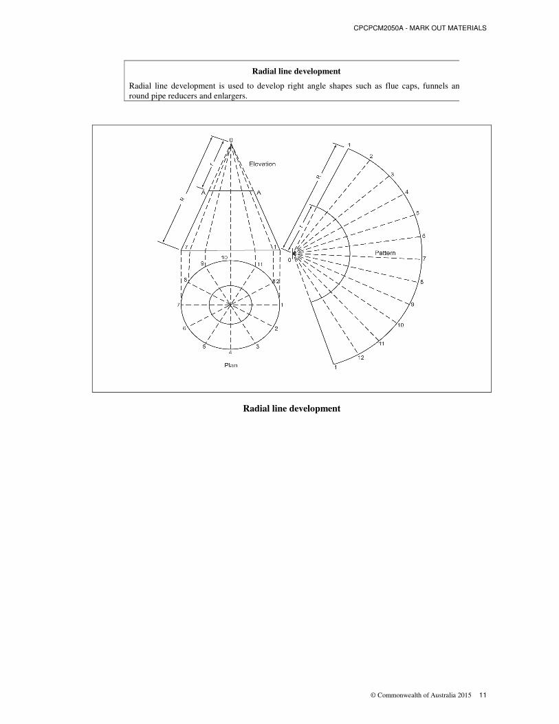
Radial line development
Radial line development is used to develop right angle shapes such as flue caps, funnels and
round pipe reducers and enlargers.
Radial line development

CPCPCM2050A – MARK OUT MATERIALS
12 © Commonwealth of Australia 2015
Triangulation
Similar to both radial line and parallel line, however it is the only method which can develop irregular
shapes. It can be used to develop square to round articles and would be used to develop patterns for
articles such as rain heads and sumps.
There are cases in which more than one method can be used to develop patterns for specific articles,
your choice of method can depend upon factors such as ease of manufacture, line restraints and
appearance of the finished article, for further information on these development methods read the
following pages.
Triangulation development method
There are cases in which more than one method can be used to develop patterns for specific articles.
Your choice of method can depend upon factors such as ease of manufacture, line restraints and
appearance of the finished article, for further information on application of these development
methods follow.

CPCPCM2050A - MARK OUT MATERIALS
© Commonwealth of Australia 2015 13
Parallel line development
Cylinder cut at 45 degrees
Step 1: Place a sheet of A3 drawing paper in the clamp on the drawing board. Check that the paper is
placed in the board squarely by lining up the top of the title block with the T Square or slide. Adjust
until paper is square.
Step 2: On the bottom left hand side of the paper place two centre lines lightly (using 2H pencil).
Allow enough space to draw a circle at the specified radius plus 15mm on the left and bottom sides.
Step 3: Now draw the bottom view of the article at the specified radius. NOTE: the radius is half the
diameter of the circle which is measured by a straight line passing through the centre point.
Front and base view of cylinder cut at 45º angle
Step 4: Draw the front view of the cylinder approx 20mm above the bottom view.
NOTE: If the lines are projected up off the bottom view the front view will be the same size as the
bottom view.
Step 5: It is now necessary to layout the pattern for the rectangular stretch-out of the cylinder, by
calculating the circumference of the cylinder.
CPCPCM2050A – MARK OUT MATERIALS
14 © Commonwealth of Australia 2015
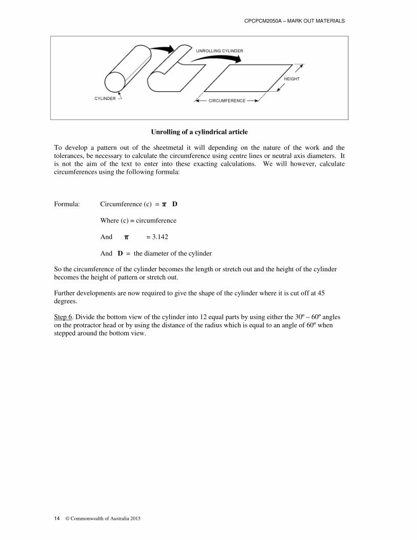
Unrolling of a cylindrical article
To develop a pattern out of the sheetmetal it will depending on the nature of the work and the
tolerances, be necessary to calculate the circumference using centre lines or neutral axis diameters. It
is not the aim of the text to enter into these exacting calculations. We will however, calculate
circumferences using the following formula:
Formula: Circumference (c) = ππππ D
Where (c) = circumference
And ππππ = 3.142
And D = the diameter of the cylinder
So the circumference of the cylinder becomes the length or stretch out and the height of the cylinder
becomes the height of pattern or stretch out.
Further developments are now required to give the shape of the cylinder where it is cut off at 45
degrees.
Step 6. Divide the bottom view of the cylinder into 12 equal parts by using either the 30º – 60º angles
on the protractor head or by using the distance of the radius which is equal to an angle of 60º when
stepped around the bottom view.

CPCPCM2050A - MARK OUT MATERIALS
© Commonwealth of Australia 2015 15
Division of base view into 12 equal parts
Step 7. In this stage we will number the points around the bottom view. The starting point is at the
seam which is placed on the shortest side of the cylinder. It is numbered by S at the seam, the next
point is 1, and working around the view until 6 is reached. At this point the number goes in reverse
back to S, as both sides of the base view are identical.
Front and base view showing all divisions
Step 8: Once all of the points have been numbered, project the points off the bottom view onto the top
view. This then indicates on the top view the length of the side when the article is divided, into 12
equal parts. Before progressing any further number the points on the bottom of the top view from S –
6 and on the top of the truncated or cut off cylinder it should be numbered S’, 1’ through to 6’, this
will enable identification of points on the top and on the bottom.

CPCPCM2050A – MARK OUT MATERIALS
16 © Commonwealth of Australia 2015
Step 9: The cylinder pattern now has to be divided up into 12 equal parts, just like the bottom view of
the cylinder. The method to do this varies from one tradesperson to the next.
The method described below is one of many. It is a method which can be used within the classroom
or the workshop. This method uses the compass to find the centre line and then it is repeated to find
the centre line of the half section.
The circumference has then been divided into 4 equal parts, it is then necessary to divide each of these
quarter spaces into three equal parts, this giving twelve equal parts. To divide this space into three
equal parts it is necessary to step off a distance (usually the distance from S to 1) this distance is
adjusted (by trial and error) until the distance steps off three times equally.
Step 10. Number all the points from S to 6 and then back to S. Project the points up to the top of the
rectangular pattern. Note that figure S occurs twice as it is the seam.
Division of pattern into 12 equal parts
Step 11. Develop the pattern out by stepping off the distance from S to S’ (from the front view) with a
compass. Then place the compass point on S (on the pattern) and transfer the distance to the line. The
same measurement can be used on the other end at S. This then gives point S’.
Then measure the distance from 1 to 1’ on the front view and transfer this distance onto the pattern.
Continue this process until all the points have been transferred. Number all of these points with the
corresponding number.
Step 12. Complete the pattern by joining the points with a smooth freehand curve or by a flexi curves
French curves. Darken in all outlines.

CPCPCM2050A - MARK OUT MATERIALS
© Commonwealth of Australia 2015 17
Completed pattern development
This step by step procedure will be referred to as various patterns are developed. Most parallel line
development uses these basic procedures; it is just the shape of truncated section which changes.
90 DEGREE ELBOW (including allowances).
The pattern for this although it is developed the same as the previous development the placement of
allowances makes this development an important exercise. In this development two types of
allowances have to be allowed for, one being the grooved seam for joining the circumference together
and the other being the joint line allowance on each section so that the two cylinders can be joined
together.
Degree elbow
There are two patterns which have to be developed for this elbow a part “A” and a part “B”, in the
development stage both patterns are identical and can be developed from the one part front view. It is
not necessary for this development to draw a full bottom view as semi-circle (half circle) is sufficient
as both parts of the circle are identical. It is also not necessary to draw a full front view of the elbow
as the joint line of the article is the same angle and shape for part A and B.

CPCPCM2050A – MARK OUT MATERIALS
18 © Commonwealth of Australia 2015
Parallel line development
Step 1: Proceed to draw the front view and a half base view. Divide the half base view (semi-circle) in
6 equal parts and project these points up and onto the front view and number these points.
Front and base view
Step 2. Calculate the circumference, (formula: circumference = ππππ x d) and draw a line equal to this
length.
Step 3. Divide this line into twelve equal parts and project the 12 equally spaced lines high enough so
that 2 patterns can be drawn, number the points S to 6 to S.
Step 4. Measure the distance from S to S’ on the front view with a pair of dividers and transfer this
distance to the pattern. This length can be used four times if the length is taken from top and bottom
lines to form a pattern starting from the top and another from the bottom. Continue this until all the
points have been transferred from the front view. Join all of these points so that the two basic patterns
are formed.
CPCPCM2050A - MARK OUT MATERIALS
© Commonwealth of Australia 2015 19
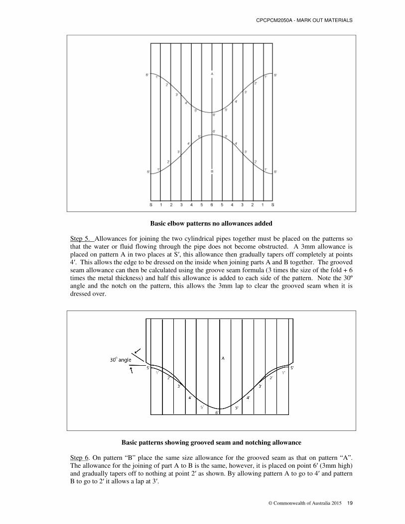
Basic elbow patterns no allowances added
Step 5. Allowances for joining the two cylindrical pipes together must be placed on the patterns so
that the water or fluid flowing through the pipe does not become obstructed. A 3mm allowance is
placed on pattern A in two places at S′, this allowance then gradually tapers off completely at points
4′. This allows the edge to be dressed on the inside when joining parts A and B together. The grooved
seam allowance can then be calculated using the groove seam formula (3 times the size of the fold + 6
times the metal thickness) and half this allowance is added to each side of the pattern. Note the 30º
angle and the notch on the pattern, this allows the 3mm lap to clear the grooved seam when it is
dressed over.
Basic patterns showing grooved seam and notching allowance
Step 6. On pattern “B” place the same size allowance for the grooved seam as that on pattern “A”.
The allowance for the joining of part A to B is the same, however, it is placed on point 6′ (3mm high)
and gradually tapers off to nothing at point 2′ as shown. By allowing pattern A to go to 4′ and pattern
B to go to 2′ it allows a lap at 3′.
CPCPCM2050A – MARK OUT MATERIALS
20 © Commonwealth of Australia 2015
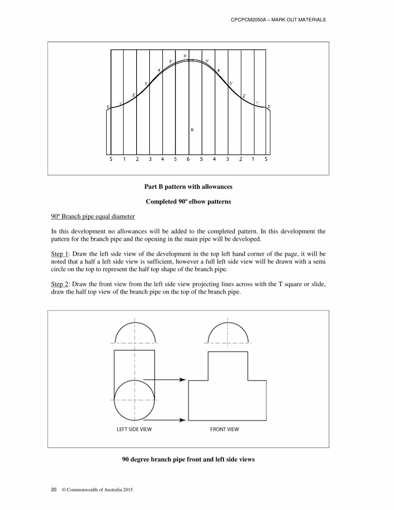
Part B pattern with allowances
Completed 90º elbow patterns
90º Branch pipe equal diameter
In this development no allowances will be added to the completed pattern. In this development the
pattern for the branch pipe and the opening in the main pipe will be developed.
Step 1: Draw the left side view of the development in the top left hand corner of the page, it will be
noted that a half a left side view is sufficient, however a full left side view will be drawn with a semi
circle on the top to represent the half top shape of the branch pipe.
Step 2: Draw the front view from the left side view projecting lines across with the T square or slide,
draw the half top view of the branch pipe on the top of the branch pipe.
90 degree branch pipe front and left side views
CPCPCM2050A - MARK OUT MATERIALS
© Commonwealth of Australia 2015 21
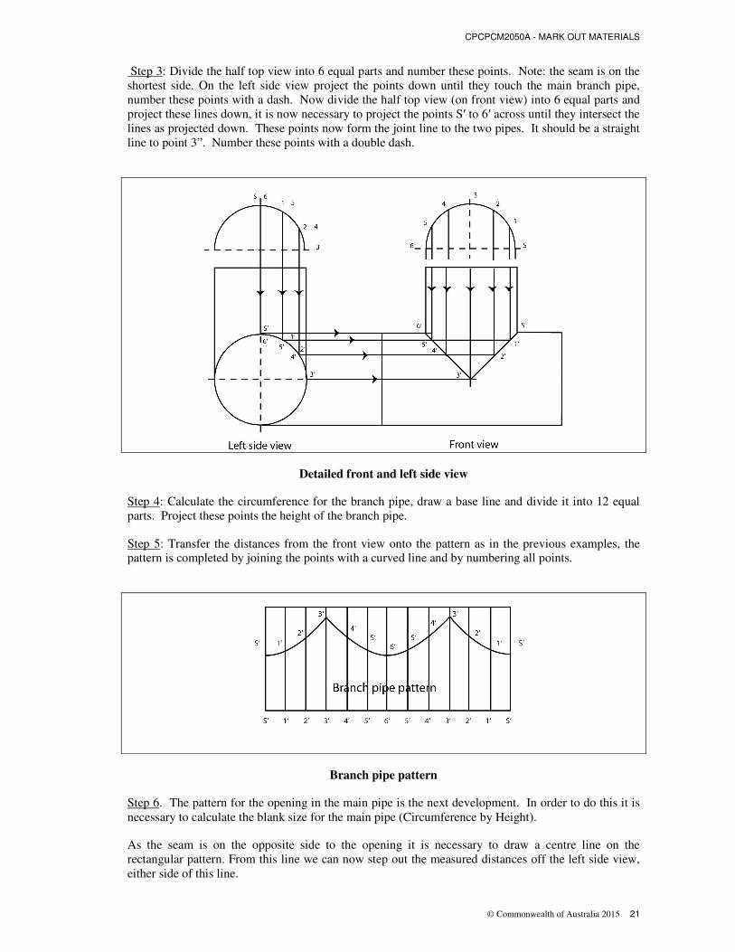
Step 3: Divide the half top view into 6 equal parts and number these points. Note: the seam is on the
shortest side. On the left side view project the points down until they touch the main branch pipe,
number these points with a dash. Now divide the half top view (on front view) into 6 equal parts and
project these lines down, it is now necessary to project the points S′ to 6′ across until they intersect the
lines as projected down. These points now form the joint line to the two pipes. It should be a straight
line to point 3”. Number these points with a double dash.
Detailed front and left side view
Step 4: Calculate the circumference for the branch pipe, draw a base line and divide it into 12 equal
parts. Project these points the height of the branch pipe.
Step 5: Transfer the distances from the front view onto the pattern as in the previous examples, the
pattern is completed by joining the points with a curved line and by numbering all points.
Branch pipe pattern
Step 6. The pattern for the opening in the main pipe is the next development. In order to do this it is
necessary to calculate the blank size for the main pipe (Circumference by Height).
As the seam is on the opposite side to the opening it is necessary to draw a centre line on the
rectangular pattern. From this line we can now step out the measured distances off the left side view,
either side of this line.

CPCPCM2050A – MARK OUT MATERIALS
22 © Commonwealth of Australia 2015
The first distance is taken from S′, 6′ to 1′, 5′ off the left side view, and transferred either side of the
centre line on the pattern.
The next distance is that of 1′, 5′ to 2′, 4′ and this distance is stepped off from the previous marks.
The last distance is from 2′, 4′ to 3′ this distance is then stepped off from the previous marks. Draw
these lines across the pattern and number these lines.
Note: in this development the distance from S′ to 1′ is the same for all points, to avoid confusion in
future developments the above procedure should always be used.
Step 7. Off the front view transfer the distance from the left hand edge to point S′, place this distance
on line S’, (on the main pipe pattern). This has now given the distance from the left hand edge of the
pipe to the opening at point S′. Do the same for 1′ and place this distance on line 1′, continue this
process until all the points are transferred onto the pattern, and draw in the shape of the opening.
Number all the points.
Completed 90º branch and main pipe patterns
45 Degree branch pipe unequal diameter
In this development the branch pipe is smaller in diameter than the main branch pipe and it enters the
main pipe at a 45 degree angle.
Step 1. Draw the left side view with the half top view above it. The branch pipe can be any height on
the left side view because the actual opening should be drawn as an oblique shape.
Step 2. Draw the front view with the branch pipe at an angle of 45 degrees with a half end shape above
it, now divide all the half top view sections into six equal parts as in the previous developments and
number these points.

CPCPCM2050A - MARK OUT MATERIALS
© Commonwealth of Australia 2015 23
Step 3. Project points S through 6 on the half end shape on left side view down until they intersect the
main branch pipe. Project these points across to the front view. Now project the points from the half
end shape on the front view down until the lines intersect the corresponding lines from the left side
view, now draw in the curved joint line.
Step 4. Develop the pattern for the branch pipe by calculating the circumference and drawing a base
line equal to this length. Then divide the base line into 12 equal parts and project these points to the
height of the branch pipe. Number these points S to 6.
Step 5. Transfer the distances off the front view branch pipe onto the pattern and draw in the shape of
the pattern. Number all points on the pattern.
45º branch pipe pattern developed from front and left side views
Step 6. Calculate the circumference for the main pipe and lay out the rectangular pattern. It is now
necessary to find the centre of the pattern and draw a line across the pattern. This is the centre line of
the opening. The next stage is to take the distance from the left side view from S′, 6′ to 1′, 5′ and step
this distance off either side of the centre line.
Then do the same for points 1′, 5′ to 2′, 4′ and from 2′, 4′ to point 3′. These distances are all different
as this is where the small pipe intersects the main pipe.
The next stage is to measure the distance from the left hand edge of the main pipe on the front view to
point S′ and place this distance on the centre line on the pattern. Now proceed to do the same for
points 1′ to 6′, then join all the joints with a line to form the shape of the opening. This shows the
completed shape of the opening.
The distance around the opening should be the same as the distance around the curved part of the
branch pipe pattern. The pattern is now complete except for the allowances for the Grooved Seam and
for joining the two pipes together.

CPCPCM2050A – MARK OUT MATERIALS
24 © Commonwealth of Australia 2015
Completed 45º branch and main pipe patterns

CPCPCM2050A - MARK OUT MATERIALS
© Commonwealth of Australia 2015 25
Lobster back bend
This development allows cylindrical pipes to change direction gradually, by placing segments or leafs
in the bend. The greater number of segments the smoother the curve, the least number of segments the
sharper the bend. For this development we will use 3 full segments and two half segments which are
on each end of the bend.
Step 1. Draw a 90 degree angle large enough to accommodate the outside radius of the bend.
Step 2. Draw the inside (throat) and outside (heel) radius of the bend from point X.
Step 3. Draw a half base view below the bend radius and to divide the half base view into 6 equal
parts. Number these points S, 1 to 6.
Step 4. Determine the number of segments required. For this bend there are 3 full segments and 2 half
segments. Using a compass bisect the heel into an angle of 45º and draw a line to point X. From this
line bisect the 45 º angle; this gives an angle of 22.5 º which is the centre line of pattern B. Draw a
line to point X.
Step 5. Bisect the two angles just found, this has now formed the joint lines of the segments. See Fig.
31.
Step 6. Project the points S to 6 on the half base view up until they reach the first joint line. This has
formed the first half segment A, there are two half segments to each full segment. Number these
points before moving on the next step.
Formation of lobster back bends half segment
CPCPCM2050A – MARK OUT MATERIALS
26 © Commonwealth of Australia 2015
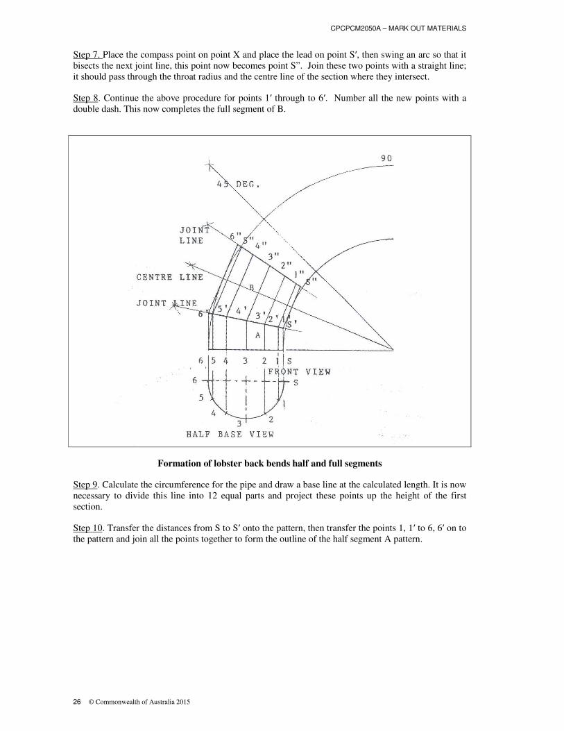
Step 7. Place the compass point on point X and place the lead on point S′, then swing an arc so that it
bisects the next joint line, this point now becomes point S”. Join these two points with a straight line;
it should pass through the throat radius and the centre line of the section where they intersect.
Step 8. Continue the above procedure for points 1′ through to 6′. Number all the new points with a
double dash. This now completes the full segment of B.
Formation of lobster back bends half and full segments
Step 9. Calculate the circumference for the pipe and draw a base line at the calculated length. It is now
necessary to divide this line into 12 equal parts and project these points up the height of the first
section.
Step 10. Transfer the distances from S to S′ onto the pattern, then transfer the points 1, 1′ to 6, 6′ on to
the pattern and join all the points together to form the outline of the half segment A pattern.

CPCPCM2050A - MARK OUT MATERIALS
© Commonwealth of Australia 2015 27
Pattern for half segment
Step 11. Although it is not always necessary to develop a full segment, a half segment can be reversed
and traced around to give a full segment, this text will develop, the full segment to show the
procedure. To develop the pattern it is necessary to have a line the length of the circumference
divided into twelve equal parts which has been numbered S to 6 to S. This line becomes the centre
line of segment B.
After dividing the line into the twelve equal parts it is necessary to project the lined either side of the
centre line.
The next step is to take the distance from the centre line of the full segment B to point S′ then check it
by measuring to point S”. Place this distance on the pattern centre line (sometimes called a datum line)
and swing an arc either side from point S.
Proceed to do this for all the other points, and draw a freehand curve connecting all the points.
You will notice that the pattern is a mirror image on both sides of the centre line.
Completed pattern development for 90º lobster back bend

CPCPCM2050A – MARK OUT MATERIALS
28 © Commonwealth of Australia 2015
RADIAL LINE DEVELOPMENT
Introduction
Radial line development is used to develop patterns for right cone frustums. It is extensively used
throughout the sheetmetal industry for flue caps, funnels and round pipe reducers or enlargers.
In radial line development, the same general procedures are followed as those used in parallel line
development, except that since the slanting lines of a right cone do not always appear in their true
length in orthogonal views, certain procedures must be followed in order to develop these lengths.
To find the true length of the side, the right cone needs to be rotated around the axis point to give the
article its true length (sometimes called its slant height), on the side of the right cone. The true length
of the side is then the distance from the apex to the given point on the side of the right cone or cone
frustum.
RIGHT CONE DEVELOPMENT
This development is used to produce patterns for various conical articles, the most common being the
flue cap.
Step 1 Draw the full shape of the base view which is circular in shape. Draw this shape in the bottom
left hand side of the paper.
Step 2: From a centre line draw a base line for the front view and measure off the height and width of
the front view. Now draw in the sides to form the apex point.
Step 3: Divide the base view into 12 equal parts each at 30º and number these points S to 6 and back to
S. Refer to Fig. 35. At this point you should notice that, half a base view would have been sufficient as
one side is a mirror image of the other side.
Step 4: Project points S to 6 up at right angles to the base line of the front view, this is where the
points on the base view are on the front view. Number theses points S through 6 and draw lines from
these points up to the apex point.
Step 5: The pattern for the right cone is developed by placing the point of the compass on the apex and
lead on S. This forms the true length (slant height) of the right cone, notice that it is longer than the
original height. Place the compass point on an apex point (on the pattern) and swing an arc, then draw
a line from the apex point to arc, this line is the distance from the apex point to S.
CPCPCM2050A - MARK OUT MATERIALS
© Commonwealth of Australia 2015 29
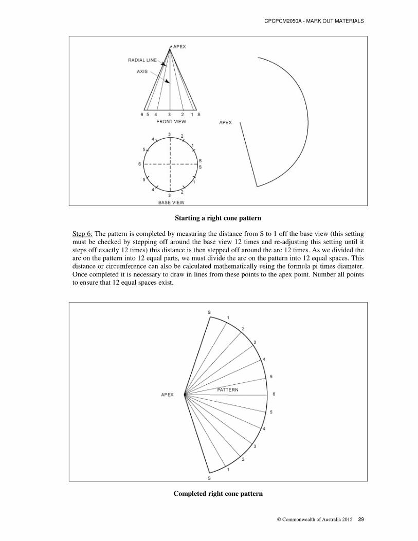
Starting a right cone pattern
Step 6: The pattern is completed by measuring the distance from S to 1 off the base view (this setting
must be checked by stepping off around the base view 12 times and re-adjusting this setting until it
steps off exactly 12 times) this distance is then stepped off around the arc 12 times. As we divided the
arc on the pattern into 12 equal parts, we must divide the arc on the pattern into 12 equal spaces. This
distance or circumference can also be calculated mathematically using the formula pi times diameter.
Once completed it is necessary to draw in lines from these points to the apex point. Number all points
to ensure that 12 equal spaces exist.
Completed right cone pattern

CPCPCM2050A – MARK OUT MATERIALS
30 © Commonwealth of Australia 2015
Cone Frustum
The cone frustum is a right cone that has been cut off, on either the bottom or the top of the cone.
There are many different types of cone frustums which can be developed out using this method, in this
text we will concentrate on two, firstly a straight cut on the top of a right cone and secondly an oblique
cut on the base of a right cone.
Step 1: Draw a half bottom view, and divide the semi-circle up into six equal parts, these points should
be numbered from S at the seam and then to 6 as in Fig. 37.
Step 2: Draw the centre line for the front view. The overall diameter can be projected up off the half
base view. At the height specified, draw a line parallel to the base line, and measure the top diameter
(or radius from the centre out each side). Now draw in a line from the base line through the top
diameter until it reaches the centre line, do the same for the other side. At this stage the two lines
should have met on the centre line to form the apex point. See Fig. 37.
Note: It is not essential on this front view to draw in the radial lines as sufficient detail to develop the
pattern already exists.

CPCPCM2050A - MARK OUT MATERIALS
© Commonwealth of Australia 2015 31
Cone frustum front and half base views
Step 3: The pattern is developed by adjusting the compass so that the distance is measured from the
apex to the base of the cone. This height is the slant height or true length of the side of the cone. Once
measured place the compass point on a point where the pattern is to be drawn from, and then swing an
arc.
Step 4: Draw a line from the apex point to the arc; this is the starting point for the pattern. The next
stage is to either calculate the circumference mathematically and measure out the pattern or to take the
distance from S to 1 and check that this distance can be stepped off six times exactly, if it doesn’t re-
adjust the compass until it does.
Step 5: With this distance, step off around the arc 12 times. Join the last point up to the apex with a
straight line, number these points S to 6 and then back to S. There is no need to draw all points back to
the apex on this pattern as there is sufficient detail here to enable the article to be made.
Initial pattern formation

CPCPCM2050A – MARK OUT MATERIALS
32 © Commonwealth of Australia 2015
Step 6: Complete the pattern by drawing in the shape of the cut off piece; this is achieved by placing
the compass point on the apex and placing the lead on the cut off point on the slant height or true
length line. This distance is then placed on the apex point on the pattern and an arc is swung. Refer to
Fig. 39. The shape is now that of the completed pattern and requires allowances to be added, before
the article is cut out and manufactured.
Completed cone frustum pattern
30º OBLIQUE CONE FRUSTUM
Step 1: Draw a half base view which is divided into six equal parts, and draw the front view which is
cut off at an angle of 30º .
Step 2: To develop this pattern it will be necessary to draw in all radial lines, these are projected off
the half base view, until they reach the base line of the cone. Radial lines are now drawn from the base
line up to the apex point.
Step 3: Where the radial lines intersect the 30º cut it is necessary to project these points across to the
edge or true length line. These lines must be parallel to the base line of the cone. On the edge of the
cone number these points S′, 1′ through to 6′. The distance from the apex to these points is now the
true length of the radial lines on the side.

CPCPCM2050A - MARK OUT MATERIALS
© Commonwealth of Australia 2015 33
Detailed 30º oblique cone frustum pattern
Step 4: To develop the pattern take the distance from the apex to point 6′, and place this distance on
the apex point for the pattern and swing the arc. Now draw in the line from the apex point to the arc.
From this point it is necessary to step off the distance from S to 1 off the half base view (check the
distance), this distance has to be stepped off 12 times around the arc. Join the last point to the arc or
circumference back to the apex point, these points should be numbered S to 6 and back to S.
Step 5: Take the distance from the apex point on the front view to point S′ and place this distance on
the apex point on the pattern. On line S (each side) place an arc, this has now formed point S′ on the
pattern, do the same to find point 1′. Continue this procedure until all points have been transferred
across. Join all the points with a free hand curve; this now forms the base line of the pattern.
Step 6: Measure the distance from the apex to the cut off line along its true length and transfer this
across to the pattern. Once this is achieved the pattern is now ready for the placement of allowances
and cutting out.
Completed pattern for 30º oblique cone frustum pattern

CPCPCM2050A – MARK OUT MATERIALS
34 © Commonwealth of Australia 2015
TRIANGULATION DEVELOPMENT
INTRODUCTION
Triangulation is a slower and more complex method of development than parallel line or radial line
development, but it more practical for many types of objects. Also it is the only method by which
irregular shapes may be developed. The general use for this development is round to square or
rectangular articles; it may also be used for conical articles where there is a minimal taper.
In the development by triangulation, the article is divided into a series as in radial development.
However there is no single apex for the triangles. The technique is one of finding the true length of
varying oblique lines; this is affected by drawing a true length diagram.
Square to round
The first article to be developed is the square to round with the round opening located centrally.
Step 1: Start by drawing the base view which comprises of a square, with a circle centrally located
within it on the left hand side of the drawing sheet.
Step 2: Draw the front view directly above the base view by projecting the points up from the top
view.
Front and top views of the square to round transition
Step 3: Divide the circle up into twelve equal parts, each of 30º, number these points starting with S in
the centre of one side and continue numbering all points until 6 is reached. On the other side number it
back to S. The points around the square also require identification; this is achieved by placing letters
around the square base, starting with A which is opposite to S. By working back around the square,
place the letters B, and C, on the two corners and letter D should be in the centre opposite 6.

CPCPCM2050A - MARK OUT MATERIALS
© Commonwealth of Australia 2015 35
Step 4: Join points D and 6 with a straight line, also join point C with points 6, 5, 4 and 3. This has
formed triangles; now join points 3, 2, 1 and S with point B to form another series of triangles. Join
point S to point A, this has completed half of the base view, complete the rest by drawing in the
appropriate lines. It can be noticed from the base view a half or quarter view would have sufficient.
Detailed front and top views of the square to round transition
Step 5: Draw a true length diagram which is the height of the article. This true length diagram enables
various lines on the base view to be compared with their vertical height to obtain the true length, for
example a ladder that has to reach up a wall 2 meters has to be longer as the ladder has to be on a
slant, if the ladder has to be 1.5 meters off the wall at the base, then the minimum length of the ladder
would have to be 2.5m. This can be calculated mathematically or by drawing down the vertical and
horizontal distances and measuring the distance between the two points, this is the purpose of the true
length diagram.
Step 6: To start the pattern, draw a line in the centre of the right hand side of the paper horizontally
and draw another line at 90º to the first line. The point at which the two lines intersect is point D.
Step 7: Measure the distance from D to C and to transfer this distance to the pattern on either side of
point D at this point is the half way point of the article. This length when taken off the base view is
true length. The distance around the outside of the square is its actual length, and doesn’t require
triangulating.
Step 8: Find the distance from point C to point 6. This can be achieved by measuring the distance from
C to 6 on the base view, this length is not true length so it needs to be triangulated, that is achieved by
placing the measured length on the base line of the true length diagram to the point on the base line,
number this point C-6. This process has found the true length or clant height between these two points.
Now place the compass point on C on the pattern and swing an arc so that it will intersect with the arc
that is drawn from the other point C, this new point is point 6. It should bisect the first line drawn on
the page, join points C and 6 with straight line.

CPCPCM2050A – MARK OUT MATERIALS
36 © Commonwealth of Australia 2015
Starting the square to round pattern
Step 9: Locate point 5 on the pattern, this is achieved by measuring the distance C to 5 off the base
view and transferring this distance onto the true length diagram, number this point C-5. By measuring
the true length or slant height off the true length diagram and placing the compass point on C. Along
this arc will be point 5, the distance from 6 to 5 will be the same distance as that on the base view. The
distance around the circular part of the base view, is true length it doesn’t require triangulating. Place a
line from point C to 5.
Locating point 5 on the pattern
If two compasses are used the distance from 6 to 5 can be set on one and left. This will ensure that this
distance remains constant as it will be used 12 times.
Step 10: Measure the distance from C to 4, place it on the true length diagram and step off the true
length of C-4, then swing an arc on the pattern from point C. On this article, this distance is the same
as C to 5. To find where point 4 is on the arc use the pre set compass (distance 6-5) and swing the arc,
the point where the two arcs intersect is point 4. Repeat the above procedure to find point 3. Join these
points back to C.

CPCPCM2050A - MARK OUT MATERIALS
© Commonwealth of Australia 2015 37
Locating points 3 and 4
Step 11: Point B is the next point of the triangle C-3-B to be located. Measure the distance off the base
view from C to B (this is true length) and swing an arc from point C, then find the true length of the
line 3 to B, by measuring the distance off the front view and triangulating this length. Then place the
compass point on 3 and swing an arc, the point of intersection is point B. The length of line 3-B
should be the same as 3-C for this article. Join points 3 to B with a line.
Locating point B on the pattern
Step 12: Repeat the procedure used in step 11 to find the following points B to 2, B to 1 and B to S.
This now leaves one point left to locate which is point A. To find this point triangulate the length from
point A to S off the base view, then swing an arc from point S. To find point A measure the length
*which is true length) from B to A, and place the compass on point B, then swing the arc until it
intersects the previous arc which will give point A. Join points as previously done with a straight line.
Step 13: Complete this pattern by drawing a free hand curve between points S to 6 to S, then joining
all other points with a straight line, also draw in the required fold lines. A way of checking the patterns
accuracy is to check that the last corner of the pattern (A-S-B) has a 90º corner, if not it will be
necessary to work back over the pattern to find any mistakes.

CPCPCM2050A – MARK OUT MATERIALS
38 © Commonwealth of Australia 2015
Completed Square to round pattern
Round to square transition
This development is similar to the first transition, except that the circular end is larger than the square
end; the same principles apply when drawing the front and base views, a true length diagram is
required. The pattern will differ in the respect that the curved section will form around the outside of
the pattern with the straight line squared section on the inside.
Step 1: Draw half base view, (a full view is not required as the half view gives sufficient detail to
develop the pattern) and then divide the semi circular base into six equal parts. Number these points S
to 6 and those on the square A, B, C, and D. Once numbered join points S, 1, 2, and 3 with B, and
points 3, 4, 5, and 6 to point C.
Round to square front and top views

CPCPCM2050A - MARK OUT MATERIALS
© Commonwealth of Australia 2015 39
Step 2: Draw the front view with a true length diagram beside it.
Step 3: Start the pattern by drawing a centre line on the paper and drawing a vertical line at 90º to the
centre line. The intersection is point D, see Fig. 50. From the front view take the length of line D to C
which is true length and step off this distance on the pattern either side of point D to give point C.
Step 4: Measure the distance of C to 6 and place this length on the true length diagram. By measuring
the distance from the top of the true length diagram to the point on the base line, the true length of the
line C to 6 is found. From points C on the pattern swing an arc so that the two arcs intersect, this point
becomes point 6, join and number these points.
Step 5: Take the distance C-5 off the front view triangulate this distance. Then place the compass
point on point C (on the pattern) and seeing an arc. The distance from 6 to 5 is taken off and half base
view from 6 to 5, (check that this distance steps off around the view 6 times exactly if not adjust the
compass until it does.) Place the compass point on point 6 and swing the arc. Repeat this procedure for
points C-4 and C-3, join and number these points.
Part round to square pattern
Step 6: Locate point B by taking the distance from 3 to B off the base view and triangulating this line.
Then swing an arc on the pattern at point 3. Then take the length of line C to B (this is true length) and
swing an arc from point C, the point of intersection is point B. Join and number these points.
Step 7: Repeat the procedures used in step 5 for points 2, 1 and S, and then to use the procedures in
step 6 to give point A.
Step 8: Draw the free hand curve around the points numbered S to 6 to S.

CPCPCM2050A – MARK OUT MATERIALS
40 © Commonwealth of Australia 2015
Completed round to square pattern.
Calculations are performed to determine job requirements
You may be required to perform various calculations prior to and during the marking out process. For
example during the pattern development process the plumber will be required to calculate
circumferences, and to demonstrate an understanding of Radius and diameters. During marking out of
copper tube the Plumber will be required to calculate total lengths, which will require some
knowledge and understanding of Bend Radius and the calculating of angles necessary to successfully
Mark out.
Material is marked out in conformance with determined measurements
Plans drawings specifications, codes etc are designed to set the highest possible standards for the
Plumbing Industry, and to provide the best possible result for customers. Set standards are to be
adhered to by the plumber whether installing or maintaining plumbing appliances, or ancillary fittings
and fixtures. It is the Plumbers task to also ensure that whilst marking out to work to the issued plans
and specifications thus ensuring conformance with the determined measurements. It is not the role of
the Plumber to change specifications or dimensions without the appropriate consent.
Dimensions are checked for accuracy and compliance to plans/specifications
After you have finished marking out it is important that you check your work against the job
plans/specifications to ensure that no errors have occurred. You should always measure twice and cut
once. Experience will guide you and raise doubts in your mind if you have measured incorrectly.
Always be guided by these doubts and re-check your calculations and measurements.

CPCPCM2050A - MARK OUT MATERIALS
© Commonwealth of Australia 2015 41
Clean up
Work area is cleared and materials disposed of:
On completion of the job you should allow time to clean up. Cleaning up includes clearing the work
site of debris and unused materials and stacking materials to aid good site management.
Tools and equipment
Cleaning, maintenance and storage of your tools and equipment is important. All tools should be
checked for correct operation. If problems are found with any tools or equipment they should be
tagged as faulty and repaired.

CPCPCM2050A – MARK OUT MATERIALS
42 © Commonwealth of Australia 2015
Documentation is completed in accordance with workplace requirements
Keeping and maintaining documentation to workplace requirements is an ever increasing task for the
plumber. However, it is important to recognize that documentation often provides the customer with
written details of the completed task outlining the specifications, which can often serve as the
customers’ copy of quality assured installation.
For the Plumber documentation may provide accurate records of the following:
1. Site clean up
2. Have waste or surplus materials been disposed of in accordance with regulations
3. Have all tools been returned to their correct location
4. Has the worksite been left in accordance with E.P.A. requirements
5. Certificate of completion and compliance
6. Manufacturers warranties and specifications
7. Quality assurance documentation
CPCPCM2050A - MARK OUT MATERIALS
© Commonwealth of Australia 2015 43
Name:…………………………………………………………
Worksheet
CPCPCM2050A – Mark out materials
The student should complete the following worksheets by answering all questions.
All worksheets should be completed before attempting any of the practical marking out.
1. A Plumbing tradesperson should be able to develop detailed surface patterns of geometric
shapes using the principles of geometry and mathematics?
List the three most common Geometric development methods.
1………………………………………………………………………………………………
2………………………………………………………………………………………………
3………………………………………………………………………………………………
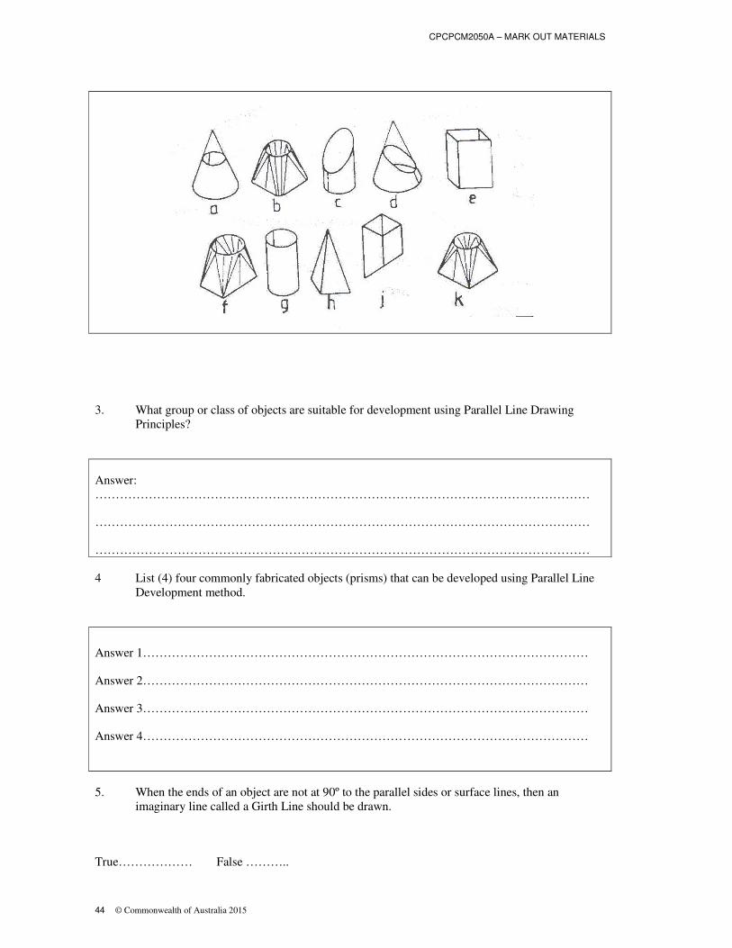
2. Shown below are ten (10) objects that can be developed by geometric development principles.
Select the objects that would be developed using the Parallel Line Development method.
Answer 1…………………………………………
Answer 2…………………………………………
Answer 3………………………………………..
Answer 4………………………………………..
CPCPCM2050A – MARK OUT MATERIALS
44 © Commonwealth of Australia 2015
3. What group or class of objects are suitable for development using Parallel Line Drawing
Principles?
Answer:
…………………………………………………………………………………………………………
…………………………………………………………………………………………………………
…………………………………………………………………………………………………………
4 List (4) four commonly fabricated objects (prisms) that can be developed using Parallel Line
Development method.
Answer 1………………………………………………………………………………………………
Answer 2………………………………………………………………………………………………
Answer 3………………………………………………………………………………………………
Answer 4………………………………………………………………………………………………
5. When the ends of an object are not at 90º to the parallel sides or surface lines, then an
imaginary line called a Girth Line should be drawn.
True……………… False ………..

CPCPCM2050A - MARK OUT MATERIALS
© Commonwealth of Australia 2015 45
6. At what angle to the parallel sides or surface lines is a girth line drawn?
Answer:
…………………………………………………………………………………………………………
7. Shown below are ten (10) objects that can be developed by geometric development principles.
Select the object that would be developed using the Radial Line Development method?
Answer 1…………………………………………
Answer 2…………………………………………
Answer 3………………………………………..
Answer 4………………………………………..
8. Define a right cone?
Answer
A right cone can be defined as
…………………………………………………………………………………………………………
…………………………………………………………………………………………………………
…………………………………………………………………………………………………………
…………………………………………………………………………………………………………
…………………………………………………………………………………………………………
CPCPCM2050A – MARK OUT MATERIALS
46 © Commonwealth of Australia 2015
…………………………………………………………………………………………………………
…………………………………………………………………………………………………………
…………………………………………………………………………………………………………
…………………………………………………………………………………………………………
…………………………………………………………………………………………………………
…………………………………………………………………………………………………………
9. Name three (3) articles that can be manufactured using patterns developed by Radial Line
Drawings principles.
Answer 1………………………………………………………………………………………………
Answer 2………………………………………………………………………………………………
Answer 3………………………………………………………………………………………………

CPCPCM2050A - MARK OUT MATERIALS
© Commonwealth of Australia 2015 47
10. Describe the method of Triangulation?
Answer
…………………………………………………………………………………………………………
…………………………………………………………………………………………………………
…………………………………………………………………………………………………………
…………………………………………………………………………………………………………
…………………………………………………………………………………………………………
…………………………………………………………………………………………………………
…………………………………………………………………………………………………………
…………………………………………………………………………………………………………
…………………………………………………………………………………………………………
…………………………………………………………………………………………………………
…………………………………………………………………………………………………………
CPCPCM2050A – MARK OUT MATERIALS
48 © Commonwealth of Australia 2015
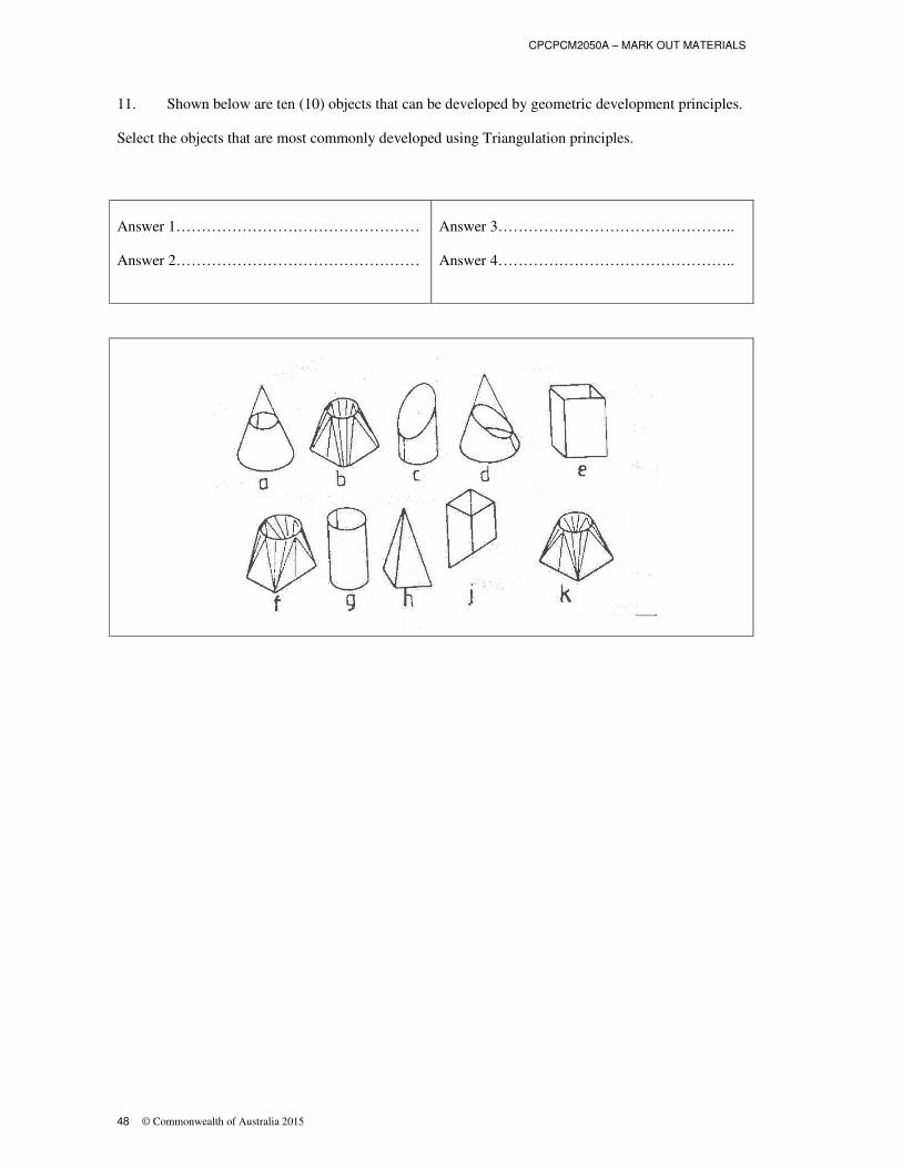
11. Shown below are ten (10) objects that can be developed by geometric development principles.
Select the objects that are most commonly developed using Triangulation principles.
Answer 1…………………………………………
Answer 2…………………………………………
Answer 3………………………………………..
Answer 4………………………………………..

CPCPCM2050A - MARK OUT MATERIALS
© Commonwealth of Australia 2015 49
12. Explain how the true length of a line may be found?
Answer
…………………………………………………………………………………………………………
…………………………………………………………………………………………………………
…………………………………………………………………………………………………………
…………………………………………………………………………………………………………
…………………………………………………………………………………………………………
…………………………………………………………………………………………………………
…………………………………………………………………………………………………………
…………………………………………………………………………………………………………
…………………………………………………………………………………………………………
…………………………………………………………………………………………………………
…………………………………………………………………………………………………………
13. What are transition pieces used for?
Answer
…………………………………………………………………………………………………………
…………………………………………………………………………………………………………
…………………………………………………………………………………………………………
…………………………………………………………………………………………………………
…………………………………………………………………………………………………………

CPCPCM2050A – MARK OUT MATERIALS
50 © Commonwealth of Australia 2015
Name:……………………………………………………………
Practical application
CPCPCM2050A – Mark out materials
Your trainer or supervisor will work with you to demonstrate and explain how to mark out materials.
The following points will be covered:
Plans and specifications are obtained from job supervisor and job requirements are determined
WHS requirements associated with the marking out of materials, and the workplace
environment, are adhered to throughout the work
Quality assurance requirements are identified and adhered to in accordance with workplace
requirements
Tasks are planned and sequenced in conjunction with others involved in or affected by the
work
Tools and equipment, including personal safety equipment, are selected and checked for
serviceability
Work area is prepared to support the efficient marking out of materials
Selected materials are checked for compliance with plans or specifications
Quantity and type of material required is calculated from plans or specifications
Job requirements are determined from plans or specifications
Dimensions for fabrication and assembly are determined and transferred
Relevant standards, codes and symbols are interpreted
Selected development method is determined as appropriate and is applied in accordance with
workplace procedures
Calculations are performed to determine job requirements
Material is marked out in conformance with determined measurements
Dimensions are checked for accuracy and compliance to plans or specifications

CPCPCM2050A - MARK OUT MATERIALS
© Commonwealth of Australia 2015 51
Work area is cleared and materials disposed of or recycled in accordance with State or
Territory legislation and workplace procedures
Tools and equipment are cleaned, checked, maintained and stored in accordance with
manufacturers’ recommendations and workplace procedures
Documentation is completed in accordance with workplace requirements
On successful completion of this practical application you are then able to attempt your final
assessment.
Trainer or Supervisor’s Signature:………………………………………………….
Date of Completion:…………………………………….

CPCPCM2050A – MARK OUT MATERIALS
52 © Commonwealth of Australia 2015
Assessment checklist
CPCPCM2050A – Mark out materials
Worksheet
Criteria Yes No
Have the worksheets been successfully completed?
Has the practical task been completed?
Are the job specifications available?
Trainer or Supervisor’s Signature: .......................................................................................
Date of Completion: .............................................................................................................