communication interfaces and protocols for advanced control of
TRANSCRIPT
Chalmers University of Technology
University of Gothenburg
Department of Computer Science and Engineering
Göteborg, Sweden, June 2015
Communication interfaces and protocols for advanced
control of high-end prosthetic hands
Master of Science Thesis in Embedded Electronic System Design
SEBASTIAN KARLSSON

The Author grants to Chalmers University of Technology and University of Gothenburg
the non-exclusive right to publish the Work electronically and in a non-commercial
purpose make it accessible on the Internet.
The Author warrants that he/she is the author to the Work, and warrants that the Work
does not contain text, pictures or other material that violates copyright law.
The Author shall, when transferring the rights of the Work to a third party (for example a
publisher or a company), acknowledge the third party about this agreement. If the Author
has signed a copyright agreement with a third party regarding the Work, the Author
warrants hereby that he/she has obtained any necessary permission from this third party to
let Chalmers University of Technology and University of Gothenburg store the Work
electronically and make it accessible on the Internet.
Communication interfaces and protocols
for advanced control of high-end prosthetic hands
Sebastian Karlsson
Examiner: Per Larsson-Edefors
Chalmers University of Technology
University of Gothenburg
Department of Computer Science and Engineering
SE-412 96 Göteborg
Sweden
Telephone + 46 (0)31-772 1000
Department of Computer Science and Engineering
Göteborg, Sweden June 2015

AbstractState-of-the-art control of hand prostheses is conventionally done by using a simplethreshold technique; one output from one input. Two input signals are necessary tocontrol the two directions of one degrees of freedom (DoF), and to switch betweendifferent predefined functions either co-contraction or a physical switch is used.However, this serial operation is unnatural and slow. The purpose of this projectwas to develop advanced control systems for high-end prosthetic devices with thepattern recognition platform BioPatRec to allow more sophisticated control schemes.Two systems considering three different hands were developed: One system for theMyoHand VariPlus Speed or the SensorHand Speed from Ottobock, and another forthe i-limb hand from Touch Bionics. In addition to these two systems, a previouslyproposed framework was further developed to specify a standard on how to interfacea motor driven device with BioPatRec. This framework guide developers how todefine their devices in BioPatRec and guide the development of the control firmware.
Keywords: Pattern recognition, Hand prosthesis, Control system.

AcknowledgementsI would like to offer special thanks to Max Ortiz Catalan, my supervisor at IntegrumAB for giving me this opportunity to write a thesis in this interesting field and forhis knowledge and technical support during the project. I also thank everyone elseat Integrum AB who have participated with valuable support and feedback. Finally,I would like to thank Per Larsson-Edefors for being my examiner.
Sebastian Karlsson, Gothenburg, June 2015

Contents
1 Introduction 11.1 Background . . . . . . . . . . . . . . . . . . . . . . . . . . . . . . . . 11.2 Goals . . . . . . . . . . . . . . . . . . . . . . . . . . . . . . . . . . . . 2
2 Development methods 32.1 Analysis of problems . . . . . . . . . . . . . . . . . . . . . . . . . . . 32.2 Requirement specification . . . . . . . . . . . . . . . . . . . . . . . . 32.3 Ethical aspects . . . . . . . . . . . . . . . . . . . . . . . . . . . . . . 42.4 Development tools . . . . . . . . . . . . . . . . . . . . . . . . . . . . 4
2.4.1 MATLAB . . . . . . . . . . . . . . . . . . . . . . . . . . . . . 42.4.2 TIVA LaunchPad and CCS . . . . . . . . . . . . . . . . . . . 52.4.3 EAGLE . . . . . . . . . . . . . . . . . . . . . . . . . . . . . . 5
2.5 Design Methods . . . . . . . . . . . . . . . . . . . . . . . . . . . . . . 52.5.1 Control firmware . . . . . . . . . . . . . . . . . . . . . . . . . 62.5.2 PCB design . . . . . . . . . . . . . . . . . . . . . . . . . . . . 62.5.3 Graphical user interface . . . . . . . . . . . . . . . . . . . . . 6
2.6 Testing . . . . . . . . . . . . . . . . . . . . . . . . . . . . . . . . . . . 62.6.1 Embedded application . . . . . . . . . . . . . . . . . . . . . . 72.6.2 Communication . . . . . . . . . . . . . . . . . . . . . . . . . . 72.6.3 PCB . . . . . . . . . . . . . . . . . . . . . . . . . . . . . . . . 72.6.4 Performance . . . . . . . . . . . . . . . . . . . . . . . . . . . . 7
3 Theory 93.1 BioPatRec: Processing and pattern recognition of myoelectric signals 9
3.1.1 Signal Recordings . . . . . . . . . . . . . . . . . . . . . . . . . 93.1.2 Signal Treatment . . . . . . . . . . . . . . . . . . . . . . . . . 103.1.3 Signal Features . . . . . . . . . . . . . . . . . . . . . . . . . . 103.1.4 Pattern Recognition . . . . . . . . . . . . . . . . . . . . . . . 103.1.5 Control . . . . . . . . . . . . . . . . . . . . . . . . . . . . . . 11
3.2 Serial Communication and Control . . . . . . . . . . . . . . . . . . . 113.3 Motor driven devices used in this work . . . . . . . . . . . . . . . . . 11
3.3.1 MyoHand VariPlus Speed and SensorHand Speed . . . . . . . 123.3.2 The i-limb hand . . . . . . . . . . . . . . . . . . . . . . . . . . 123.3.3 Servo motors . . . . . . . . . . . . . . . . . . . . . . . . . . . 12
i
4 Design and implementation 144.1 The system for the MyoHand VariPlus Speed and the SensorHand
Speed . . . . . . . . . . . . . . . . . . . . . . . . . . . . . . . . . . . 144.1.1 Control unit . . . . . . . . . . . . . . . . . . . . . . . . . . . . 15
4.2 The i-limb system . . . . . . . . . . . . . . . . . . . . . . . . . . . . . 184.2.1 Control unit . . . . . . . . . . . . . . . . . . . . . . . . . . . . 184.2.2 PCB for motor control . . . . . . . . . . . . . . . . . . . . . . 204.2.3 Communication interface between BioPatRec and the Firmware 214.2.4 Test GUIs . . . . . . . . . . . . . . . . . . . . . . . . . . . . . 22
4.3 A proposed standardised interfacing framework . . . . . . . . . . . . 234.3.1 Defining a new device . . . . . . . . . . . . . . . . . . . . . . 234.3.2 Control structure and communication protocol . . . . . . . . . 24
5 Results 275.1 The system for the MyoHand VariPlus Speed and the SensorHand
Speed . . . . . . . . . . . . . . . . . . . . . . . . . . . . . . . . . . . 275.2 The i-limb system . . . . . . . . . . . . . . . . . . . . . . . . . . . . . 28
6 Discussion 296.1 System latency and Power consumption of the MyoHand VariPlus
Speed and the SensorHand Speed . . . . . . . . . . . . . . . . . . . . 296.2 The proposed standardised interfacing framework . . . . . . . . . . . 306.3 Future development . . . . . . . . . . . . . . . . . . . . . . . . . . . . 31
7 Conclusion 32
Bibliography 33
ii

1Introduction
The hand is a powerful tool and its loss causes severe physical and psychologicaldrawbacks. A hand prosthesis is an artificial device that is used as a replacementfor the lost hand. A highly desirable feature for the control of artificial hand limbsis prediction of simultaneous limb motions.
In clinics around the world, the state-of-the-art technology for rehabilitation of am-putees is commonly a dual-site controlled myoelectric prosthesis [1]. The method foractivating such a device is simply controlled using a threshold detection technique,one output signal from one input signal which is the myoelectric signals (MES) ofa group of muscles. Two input signals are necessary to control the two directions ofone degree of freedom (DoF), and to switch between different predefined functionseither co-contraction or a physical switch is used. However, such a serial opera-tion is unnatural and slow. The lack of intuitive control is one of the reasons thatthese devices are not used regularly. Surveys reveal that 30% to 50% of upper limbamputees do not use their prosthetic devices regularly [2].
1.1 BackgroundDespite the impact of losing a hand and the functionalities that a hand prosthesisoffer; the numbers of amputees requiring a prosthesis is too small to motivate rapiddevelopment. This is one reason why control interfaces and mechanisms barely havechanged in the past 40 years [3]. Robotic hand prostheses with one or two DoF withthe functionality to open/close or pronate/supinate the wrist have been commer-cially available since early 1970’s [3].
Products with several DoF have been developed in relatively recent years and aretoday commercially available. The i-limb hand from Touch Bionics [4], the bebionichand from RSL Steeper [5], the Michelangelo hand from Ottobock [6] and Vincentfrom Vincent systems [7] are the most used multifunctional prostheses with severalDoF. These hands, as devices with only one DoF, are controlled using the standardcontrol interface with two input control signals. Even though these hands offer so-phisticated functionality they are currently controlled in an unnatural manner. Thisis where the research take place today; control methods to achieve intuitive controland feedback to the user. Instead of using the two input signals to only controlone DoF at a time, a communication protocol could be applied to select functionsindividually or simultaneously.
1
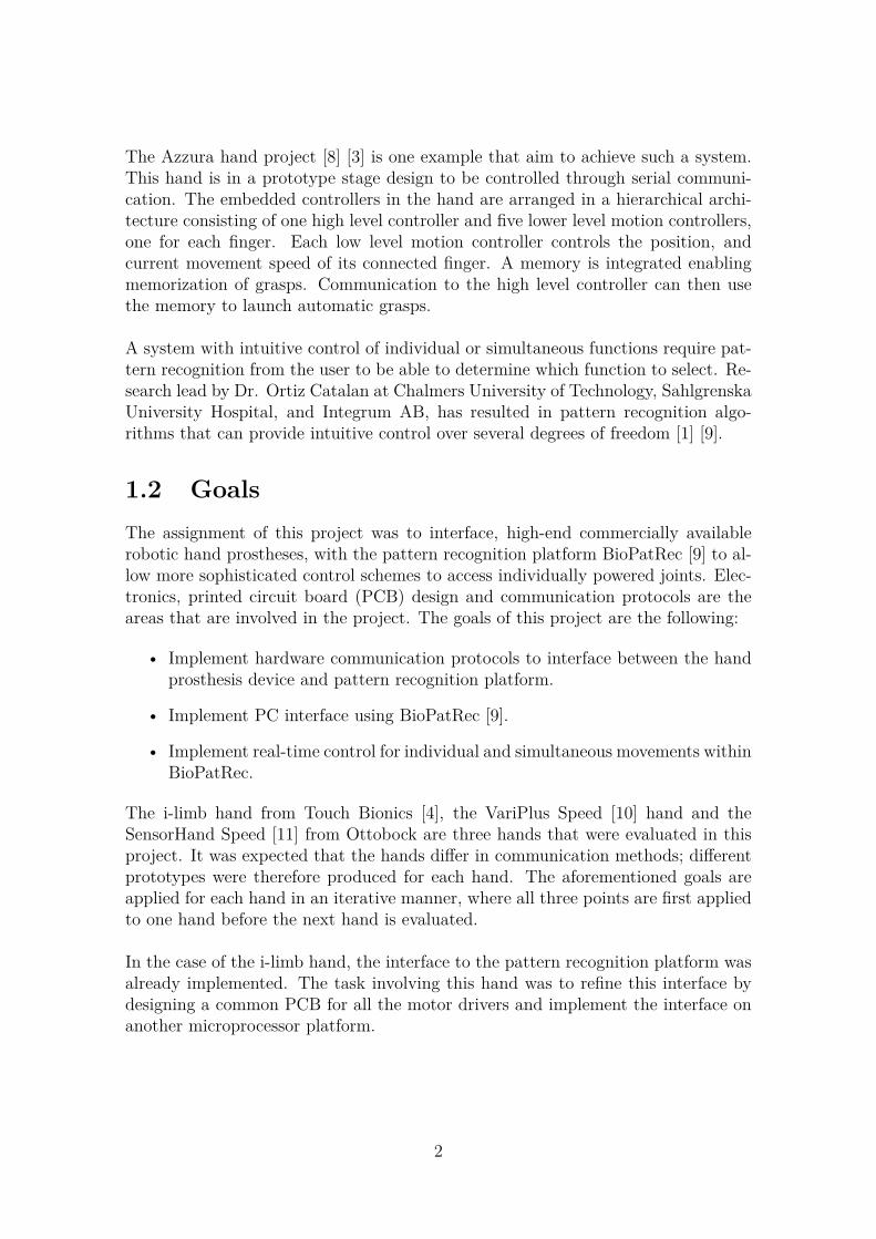
The Azzura hand project [8] [3] is one example that aim to achieve such a system.This hand is in a prototype stage design to be controlled through serial communi-cation. The embedded controllers in the hand are arranged in a hierarchical archi-tecture consisting of one high level controller and five lower level motion controllers,one for each finger. Each low level motion controller controls the position, andcurrent movement speed of its connected finger. A memory is integrated enablingmemorization of grasps. Communication to the high level controller can then usethe memory to launch automatic grasps.
A system with intuitive control of individual or simultaneous functions require pat-tern recognition from the user to be able to determine which function to select. Re-search lead by Dr. Ortiz Catalan at Chalmers University of Technology, SahlgrenskaUniversity Hospital, and Integrum AB, has resulted in pattern recognition algo-rithms that can provide intuitive control over several degrees of freedom [1] [9].
1.2 GoalsThe assignment of this project was to interface, high-end commercially availablerobotic hand prostheses, with the pattern recognition platform BioPatRec [9] to al-low more sophisticated control schemes to access individually powered joints. Elec-tronics, printed circuit board (PCB) design and communication protocols are theareas that are involved in the project. The goals of this project are the following:
• Implement hardware communication protocols to interface between the handprosthesis device and pattern recognition platform.
• Implement PC interface using BioPatRec [9].
• Implement real-time control for individual and simultaneous movements withinBioPatRec.
The i-limb hand from Touch Bionics [4], the VariPlus Speed [10] hand and theSensorHand Speed [11] from Ottobock are three hands that were evaluated in thisproject. It was expected that the hands differ in communication methods; differentprototypes were therefore produced for each hand. The aforementioned goals areapplied for each hand in an iterative manner, where all three points are first appliedto one hand before the next hand is evaluated.
In the case of the i-limb hand, the interface to the pattern recognition platform wasalready implemented. The task involving this hand was to refine this interface bydesigning a common PCB for all the motor drivers and implement the interface onanother microprocessor platform.
2

2Development methods
In this chapter, the challenges are analyzed and solutions are proposed to addressthem. The chosen development tools are listed and the advantages of their utilizationare described in addition to the testing methods.
2.1 Analysis of problemsThe project comprises different disciplines ranging from PCB design and electronics,to software programing and communication protocols. Because of the high level ofdependencies between different disciplines and modules, it is necessary to define clearinterfaces and specifications. Limitations in hardware because of constraints in func-tionality and performance and, the other way around, functionality and performancedemand certain support by the system. One of the main problems is to identify thesedependent relations and to integrate all modules into a well-functioning system.
The project also concerns the end users, although the goal is to design prototypesthat are not meant for commercial usage; each prototype has to provide sophisti-cated functionality as an amputee want to use it. This means that real-time controlfor individual and simultaneous movements should be implemented.
Providing low latency, reliable control and low power consumption are three specifictechnical challenges that are considered in this project. Different analyses of the sys-tem considering the different parts is necessary, identifying the sources of varianceand make decisions for the design. Decisions concerning compromises between inde-pendent optimal solutions and also compromises between subsystems. An exampleof such a source in this project is the firmware that is a critical sub-system of thedesign that comprises of several components which are non-trivial to implemented.
2.2 Requirement specificationThe goal of this project was to interface, high-end commercially available, robotichand prostheses with the pattern recognition platform BioPatRec [9] to create moresophisticated control schemes. The design, implementation and development of theprototype systems need to consider medical requirements since the systems use,and are meant to be used, as medical devices. In this project the requirementsare divided into four groups: Functionality, Development, System performance and
3

Prototype design.
Each prototype system that is built upon different robotic hand prostheses should beable to provide real-time control for individual and simultaneous movements withinBioPatRec. Priority was given to implement individual movements and then simul-taneous movements.
The development of medical devices containing software requires knowledge of whatthe software is intended to achieve and that the use of the software fulfill thoseintentions with acceptable risks. Integrum’s implementation of the IEC 62304 stan-dard is used in this project to provide a framework of the development process ofsoftware for medical devices.
Power consumption and system latency are the two parameters that are consideredfor performance. Since the pattern recognition platform BioPatRec [9] is not yetportable to be implemented on a stand-alone microprocessor, this sub-system isnot considered for performance in this project. However, the control and interfac-ing firmware coupled with its respective robotic hand prosthesis is expected to bedriven by a 7.4V 2200mAh lithium ion battery and be able to operate 24h beforethe battery need to be recharged. Approximately 30ms is considered as acceptablesystem latency for the system to send a control command and then receive feedbackif the command is accepted or not.
The design of the prototype systems is considered as low priority in this projectwhere design to achieve functionality is the main focus rather than cosmetic design.The systems should be easy to setup consisting of one connection to a PC and thecontrol signals should be grouped to match the standard interface for robotic handprostheses.
2.3 Ethical aspectsSince this project didn’t use any human data nor did any experiments with patients,we don’t consider any ethical aspects.
2.4 Development toolsThis section describes the tools that has been used for development of the softwareand hardware in this project.
2.4.1 MATLABMathWorks MATLAB [12] is a useful tool for pattern recognition processing whereasBioPatRec [9] is implemented using this tool. In this project, MATLAB is chosenas the main tool for designing, testing and implementing the interface betweenBioPatRec and the robotic hand prostheses. MATLAB provides a direct and simple
4

way to handle data and algorithms using a combination of functions, scripts andcommand-line control. The broad selection of built-in functions that are accessi-ble at an abstract level makes it convenient to design without considering target-specific implementation details. The graphical user interface design environment(GUIDE) [13] is used in this project to create GUIs to interact with the variouscontrol parameters.
2.4.2 TIVA LaunchPad and CCS
The Tiva C Series LaunchPad Evaluation Kit [14] is a low-cost evaluation platformfrom Texas Instruments (TI). This platform, together with the integrated develop-ment environment (IDE) Code Composer Studio (CCS) [15] provides tools to de-velop and debug embedded applications with C/C++ programming. Configurablemodules with pre-defined function libraries allow development at a high abstractionlevel that is easy to use. Considering the limited timeframe of this project, it isimportant to save development time. This platform is therefore useful to implementthe control systems in this project with acceptable performance. Modules used forserial communication and signal generation are particularly useful in this projectfor the communication interfaces from the microprocessor to the PC interface andconnected hand prosthesis.
2.4.3 EAGLE
EAGLE PCB design software [16] is a tool that is commonly used by engineersworldwide. The schematic editor, layout editor and library editor allows the user tocustomize components and design with precision to meet their individual require-ments. The free version of EAGLE that allow two-layer designs is used in thisproject to create a BoosterPack [17] for the Tiva LaunchPad platform.
2.5 Design Methods
Each prototype system was created considering the requirements from its connectedhand prosthesis. Interfacing the different sub-systems was a major part in the design.The basic building blocks in BioPatRec [18] for communication and control is used,where the interfaces to the systems in this project are designed to be as modular aspossible. Reuse of functions and settings allow flexibility in the development, wherechanges in one part of a prototype system don’t have a large impact on the rest of thesystem. MATLAB and CCS is used to create the communication interface betweenBioPatRec and the control firmware. Basic serial communication and experiencesfrom the TI and MathWorks communities were combined to create high-level com-munication interfaces between the BioPatRec platform and the microprocessor. Inthe case when creating the interface between the hand and the microprocessor, thecommunication requirements of the hand control the configuration of the interfacethat is made using CCS.
5

2.5.1 Control firmwareThe control firmware for each prototype system was designed, as for the interfaces,to be as modular as possible. The firmware translates the commonly used controlcommands from BioPatRec [18] to the corresponding specific commands to its con-nected hand. The communication requirements of the connected prosthesis hand andBioPatRec determine implementation of the firmware, since these are both stand-alone products. CCS was the tool used when created the firmware, where hardwaremodules and function libraries were used to design at a high hardware abstractionlevel. This tool also provides detailed debugging tools for the firmware to analyzesystem behavior.
2.5.2 PCB designThe free version of EAGLE PCB design software [16] was used in this project.Certain objectives were considered when designing with this tool, as shown in thefollowing listing.
• No 90 degrees wires are used.
• 24mil wide wires are used for the input supply source and 12mil wide wiredare used in the rest of the design.
• Wires are routed to utilize the available space.
• Using bottom and top ground layers.
2.5.3 Graphical user interfaceThe graphical user interface design environment (GUIDE) [13] in MATLAB wasused to create user interfaces. This tool uses a drag and drop concept for the designand generate files where the functionalities of the GUI can be specified. Each GUIfor each prototype system was designed using the same structure for connectingand disconnecting to the microprocessor. The functionalities of the connected handdetermine what parameters that can be controlled and what feedback that can becaptured and visualized to the user.
2.6 TestingVerifying a system can be carried out in several ways and has to be done thoroughly,since it is the only way to guarantee quality. The most efficient option, both insoftware and hardware, is formal verification, but due to its complicated and time-consuming nature this project uses sets of test cases most of the time. If the design isverified against a good coverage of possible inputs, then it is a high probability thatthe system is functioning without a failure during its operation can be guaranteed.In this project, different sub-systems were first tested separately and then togetheras a whole system.
6

2.6.1 Embedded applicationThe embedded application consisting of the control firmware and interfaces imple-mented on the microprocessor are testing thoroughly using the CCS debugger. Thistool was used to analyze the behavior of the application to verify that each hardwaremodule and function was implemented and functioning as intended.
This method confirms that the application is configured correctly and observe thestate of the implementation at specific stages. Although this is a powerful tool tofind errors, it is still hard to capture timing issues. Timing issues are consideredby execution the firmware in segments, verifying the behavior up to a specific pointbefore continuing the execution.
2.6.2 CommunicationThe serial communication between BioPatRec and the microcontroller was testedusing the MATLAB debugger and the CCS debugger. Verifying that the connectionis configured as intended was done by comparing the sent and received value onboth ends. On the other end, the serial communication between the hand and themicrocontroller was tested using the CCS debugger. Before testing the connectionto the hand, the microcontroller was tested using an oscilloscope to verify the signallevels and if the messages are constructed as intended according to the communi-cation protocol requirements of the connected hand. The connection to the handwas then verified by observing how the hand behave according the command thatis sent and, if applicable, analyzing the given feedback.
2.6.3 PCBTwo methods were used in this project when testing and verifying the functionalityof the PCB design. First, the design was tested if it is manufacturable using thestandard design rule check (DRC) in EAGLE. Second, when the board is manu-factured and all the components are mounted, the design is connected to a TivaLaunchPad [14] configured with the intended firmware where the functionality istested by verifying the correct output to a given input.
2.6.4 PerformanceSystem delay and power consumption are the two parameters that are consideredfor performance in this project. Timers in MATLAB are useful to measure the exe-cution time of segments in the system. More specific, timers were used to measurethe execution time of sending a command and to measure the response time fromthe microprocessor.
Power consumption was measured for the hand and the embedded application, sep-arately and all together using a multimeter to get an indication how much powerthe system is consuming. A BoosterPack for the motor controllers was designed andmanufactured for the prototype system with the i-limb hand from Touch Bionics [4].
7
In this case, the power consumption of the BoosterPack is included with the systemall together.
8
3Theory
3.1 BioPatRec: Processing and pattern recogni-tion of myoelectric signals
The simple one-muscle one-function approach for ordinary prosthetic control is un-sophisticated considering the complexities of Electromyography (EMG) crosstalk,muscle co-activation, and the contribution of deep muscles [19]. This has motivatedthe use of a pattern recognition approach for prosthetic control, by processing mul-tiple myoelectric signals to achieve control of many more movements.
BioPatRec is introduced as an open source software as an effort to provide a com-mon research platform for development and evaluation of algorithms in prostheticcontrol [9]. All the required functions for myoelectric control, ranging from dataacquisition to real-time evaluation, are included in BioPatRec. In order to facili-tate utilization, the functionalities are available through GUIs. These functions andGUIs are implemented and divided in the following modules:
• Signal Recordings
• Signal Treatment
• Signal Features
• Pattern Recognition
• Control
The modular architecture of BioPatRec provide flexibility for implementation of newalgorithms, by allowing modification, enhancement, or replacement of any modulewithout affecting the others. Fig 3.1 shows how these modules are linked and struc-tured together. The following sections briefly describes these different modules,further details can be found in the online hosting platform [18].
3.1.1 Signal RecordingsRecording of bioelectric signals is the first step in the pipeline. Three differentways of signal acquisition can be performed, each serving different purposes [9]:(1) One-shot recordings are mainly used to verify the functionality of the hardwareand inspecting the signal quality. (2) Recording session, the user is provided with
9

������
�������
��������
������
������
���������
������
�������
��������
�������������
�� �����������
�
�������������������
�������
�
��
Figure 3.1: BioPatRec flow diagram. BioPatRec is organized in different modulesthat allows replacement or modifications without affecting each other, given thatthe structure is preserved.
visual instructions to perform pre selected movements and the signals from the userare recorded. (3) Recordings for real-time control, the settings from the recordingsession are stored in order to reproduce the setup in real-time control.
3.1.2 Signal TreatmentThe recording session intend to capture as much information of the recorded signalas possible. The signal treatment module aim to optimize this information to beused for pattern recognition [9]. The BioPatRec wiki [18] list these optimizationsand show how they are implemented in routines that allow: removing channels andmovements that are of no interest, removing transient periods of the contraction,filtering the signals, and order the signal into segments.
3.1.3 Signal FeaturesThe majority of pattern recognition algorithms require discrete values of the recordedsignals, commonly known a signal features [9]. BioPatRec include 27 signal fea-tures that are extracted from the treated signal segmentation, handled by the signaltreatment module. The result can then be used as input data to various patternrecognition algorithms.
3.1.4 Pattern RecognitionThe pattern recognition module is organized in two classifications; Offline classifi-cation and Real-time classification. This separation offer utilization and flexibilityduring implementation and testing of new algorithms, were recorded sessions can beused to ease the process flow [9].
The Offline pattern recognition is implemented in three phases: training, validation,and testing [9]. Independent data sets are created for each of these phases usingpre-recorded recording sessions. The training and validation sets are used for thelearning process [18] to specify a classifier. After the completion of this process, thetesting set is used to evaluate the performance of the trained classifier [9].
The Real-time pattern recognition constantly delivers predictions of movements [9].These movement predictions can then be coupled with a prosthetic device or a
10

virtual reality. The routines that are used to achieve these predictions require aclassifier that is specified from the offline phase [18].
3.1.5 ControlBioPatRec is initially released with two control algorithms: Majority voting andBuffer output [9]. The majority voting method provide stability by filtering sporadicmisclassifications at the cost of delayed response. This method uses a buffer todetermine which movement that should be controlled, by choosing the movementwith the most predictions within the buffer window. The Buffer output method usesa similar strategy. A threshold is set to determine if a predicted movement should beperformed. In comparison the Majority voting method, the Buffer output methodsallow control of simultaneous movements. In addition to these two algorithms, othercontrol strategies or post-processing methods can be applied in order to achievefurther sophisticated control of the system [9].
3.2 Serial Communication and ControlSerial point-to-point communication is preferable to transfer data when communica-tion speed is not of high concern for performance. A serial communication protocolthat is commonly used between embedded systems is the UART protocol [20]. Thisprotocol is, in most cases, simply configured by four parameters: baud rate, paritybit, the number of data bits included in one package and the number of stop bits.The baud rate specify the modulation rate of data transmission as bits per second.The parity bit is used as a form of error detecting code and is added at the endof the package. This bit indicate if the summation of the bits within a package iseven or odd. The number of data bits in a package is usually set to eight, but canbe configured by the user depending on what UART module that is used. Fig 3.2shows the structure of a UART package.
����������������� ��������
���������� ����� ������ ������������ ������������ ������ ����������
���������
������
Figure 3.2: This figure show the general structure of a UART package. The numberof Data bits may vary depending on how the connection is set up, as well as theparity bit that can be disabled if error checking is not needed.
3.3 Motor driven devices used in this workCommunication and control requirements as well as technical details of a robotichand prosthesis determine the implementation of its connected control systems.Since digital control of such devices is relatively unexplored where different handshave different requirements, these control systems need to be tailored for each device.
11

Section 3.3.1-3.3.3 describes the technical details of the motor driven devices thatare used in this project.
3.3.1 MyoHand VariPlus Speed and SensorHand Speed
The MyoHand VariPlus Speed from Ottobock [10] is one of the most commonly usedprosthetic hand. This hand is design for robustness and performance rather thanflexibility or several degrees of freedom. Its high gripping force (up to 100N) andspeed (up to 300mm/s) make it possible to grip objects precisely and quickly [10].Since the electronics of the hand doesn’t readjust the gripping strength automati-cally, the targeted muscles for control have to hold and position the gripped item.Because of this feature, this hand is recommended for active patients with a lowamputation level in particular.
The SensorHand Speed from Ottobock [11] feature the same features as the Myo-Hand VariPlus Speed. In addition as the name indicate, this hand feature a moresophisticated sensor system.
3.3.2 The i-limb hand
The i-limb hand from Touch Bionics [4] is a prosthetic hand with five individuallypowered and architectured fingers. The hand is programmed with 14 predefined grippatterns. These patterns are controlled and selected through the two input signalsand by manually rotating the thumb to create different grasping options. The handis design for proportional control; the stronger the input signal, the faster the fingersmove. Auto grasp is another feature of this hand. This feature can sense when agripped object is slipping and adjust the grip to secure it.
3.3.3 Servo motors
Two servo motors are integrated in a device that is used to tilt and rotate a connectedhand. The angle of each motor is determined by the pulse width of its connectedcontrol signal. This signal modulation is called Pulse width Modulation (PWM).These two PWM signals are configured at 50Hz and can be generated with a pulsewidth ranging from 1ms(min) to 2ms(max), according to the specification of themotors, Fig 3.3. This device including the two motors was created at Integrum ABand is called the PanTilt.
12
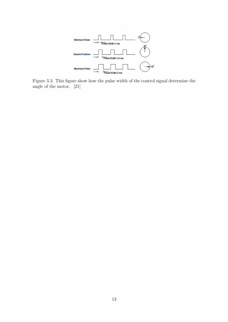
Figure 3.3: This figure show how the pulse width of the control signal determine theangle of the motor. [21]
13

4Design and implementation
Two control systems have been developed in this work. One that is used for controlof the MyoHand VariPlus Speed [10] or the SensorHand Speed [11], and the otheris used for control of the i-limb hand [4]. Both these systems are built up by severalparts where each part is necessary to achieve the desired functionality and fulfillthe requirements. Fig 4.1 shows a general overview of the structure and majorcomponents of these systems. A description of the design and implementation ofeach part within the two systems is given in this chapter.
Figure 4.1: This figure show a system overview of the control system, includingthe three major parts: Pattern recognition, control firmware, and the connectedprosthetic device.
4.1 The system for the MyoHand VariPlus Speedand the SensorHand Speed
The purpose of this system was to create a control interface between BioPatRec anda MyoHand VariPlus Speed [10] or a SensorHand Speed [11]. The data flow startswith predicting a movement using BioPatRec. Control commands of this movementis then sent to a control firmware which translate the information to send the cor-responding control signals of the connected hand. These signals are in the end sentto the hand to perform the intended movement. Fig 4.1 shows the structure andcomponents of this data path.
This system also feature a feedback data path. Both the MyoHand VariPlus Speedand the SensorHand Speed include sensors. The information from these sensors arecaptured by the firmware and then used to generate a feedback signal and visualfeedback to the user. Fig 4.2 shows the structure and components of this feedbackdata path.
14

Figure 4.2: This figure show the data path of the sensor information. The feedbackdata can be used to generate feedback directly to the user and it can be used asinput back to BioPatRec.
4.1.1 Control unitThe control unit was implemented using the TIVA LaunchPad [14] platform. Asmentioned in section 2.4.2, the TIVA LaunchPad platform is a useful tool withconfigurable modules and pre-defined function libraries. In this system, the systemclock is configured at 1MHz.
Communication interface between a PC and the firmware
In this system the UART module is used to create the communication interfacebetween a PC and the firmware. Section 3.2 describes what parameters that needto be considered when using the UART protocol. Table 4.1 shows the setup of theseparameters for the UART module in this system. These values were chosen as theyare setup in BioPatRec to be able to establish a connection.
Parameter ValueBaud rate 115200Number of data bits 8Number of stop bits NoneParity bit None
Table 4.1: This table shows how the parameters used for serial communication isconfigured.
The TIVA LaunchPad platform feature several UART modules that can be usedfor multiple connections. In this system, the module called UART0 is used for thecommunication interface between a PC and the microprocessor. This module usethe debugging port to send and receive data. The debugging port uses a micro-USBconnector, which can easy be connected to a PC with a micro-USB to USB cable.
Communication interface between the firmware and its connected hand
A communication interface between the firmware and its connected hand is imple-mented. Due to confidential information of the control of the hands I’m not allowed
15

to describe the design of this interface, nor the communication protocol that is ap-plied.
A PCB was created for the necessary circuitry combined with the connectors forthe control signals to the hand. This PCB was designed as a BoosterPack to beattached to the TIVA LaunchPad platform. It includes few components and havespace to be combined with other designs.
Sensor feedback
The feedback signal that is generated using the information from the sensors in thehands is modulated as a PWM signal. The frequency of this signal reflects thevalue that is capture from the sensors; the frequency range up to 10Hz. Two timermodules are used to generate this signal: one determine the duty cycle, and theother determine the period. Fig 4.3 shows how these timers are used to generatethe signal. The intended usage of this signal is discussed in section 6. If selected,the feedback data is also sent to the connected PC.
Figure 4.3: This figure shows how the timers are used to generate the PWM signal.Timer0 is used to determine the pulse width of the signal and Timer1 is used todetermine the period if the signal.
Software
The firmware is divided into the following functions:
• main(): The main function.
• DeviceInit(): This function initialize the modules that are used in this system.
• UARTIntHandler(): This function handle interrupts from the UART modulewhen data is available.
• OBHand_sendCommand(): This function send commands to the connectedhand.
• TimerIntHandler(): Each timer has its own interrupt function. These func-tions are used to generate the feedback signal.
Fig 4.4 shows how the functions are structured and connected to each other.
16
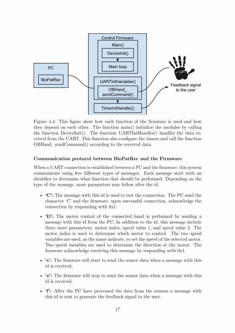
Figure 4.4: This figure show how each function of the firmware is used and howthey depend on each other. The function main() initialize the modules by callingthe function DeviceInit(). The function UARTIntHandles() handles the data re-ceived from the UART. This function also configure the timers and call the functionOBHand_sendCommand() according to the received data.
Communication protocol between BioPatRec and the Firmware
When a UART connection is established between a PC and the firmware; this systemcommunicate using five different types of messages. Each message start with anidentifier to determine what function that should be performed. Depending on thetype of the message, more parameters may follow after the id.
• ‘C’: The message with this id is used to test the connection. The PC send thecharacter ‘C’ and the firmware, upon successful connection, acknowledge theconnection by responding with 0x1.
• ‘D’: The motor control of the connected hand is performed by sending amessage with this id from the PC. In addition to the id, this message includethree more parameters: motor index, speed value 1, and speed value 2. Themotor index is used to determine which motor to control. The two speedvariables are used, as the name indicate, to set the speed of the selected motor.Two speed variables are used to determine the direction ot the motor. Thefirmware acknowledge receiving this message by responding with 0x1.
• ‘s’: The firmware will start to send the sensor data when a message with thisid is received.
• ‘z’: The firmware will stop to send the sensor data when a message with thisid is received.
• ‘f’: After the PC have processed the data from the sensors a message withthis id is sent to generate the feedback signal to the user.
17
Test GUI
A MATLAB GUI was made for this system which is used for simple control ofthe connected hand using buttons to send the control messages. This GUI wasdesigned specifically for the the MyoHand VariPlus Speed and the SensorHand Speedwhich include confidential information of the hands. Therefore, no further detaileddescription can be presented in this report.
4.2 The i-limb systemAn interface between BioPatRec and the i-limb hand have already been developedat Integrum AB. This interface was implemented on the Picollo platform [22] anduse external motor driver boards, and a separate breadboard to connect the compo-nents. The i-limb hand was re-engineered to enable control of the motors by theseexternal drivers.
The task involving the i-limb hand was to refine this interface by developing a com-mon PCB for all the motor drivers and implement the control firmware on the TIVALaunchPad platform.
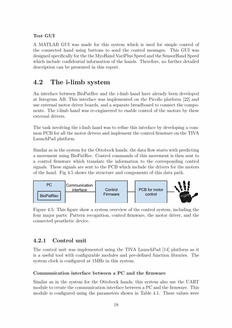
Similar as in the system for the Ottobock hands, the data flow starts with predictinga movement using BioPatRec. Control commands of this movement is then sent toa control firmware which translate the information to the corresponding controlsignals. These signals are sent to the PCB which include the drivers for the motorsof the hand. Fig 4.5 shows the structure and components of this data path.
Figure 4.5: This figure show a system overview of the control system, including thefour major parts: Pattern recognition, control firmware, the motor driver, and theconnected prosthetic device.
4.2.1 Control unitThe control unit was implemented using the TIVA LaunchPad [14] platform as itis a useful tool with configurable modules and pre-defined function libraries. Thesystem clock is configured at 1MHz in this system.
Communication interface between a PC and the firmware
Similar as in the system for the Ottobock hands, this system also use the UARTmodule to create the communication interface between a PC and the firmware. Thismodule is configured using the parameters shown in Table 4.1. These values were
18
chosen as they are setup in BioPatRec to be able to establish a connection.
The UART module called UART0 is used for the communication interface in thissystem. This module is simple to connect to a PC since it use the debugging portto send and receive data.
Communication interface between the firmware and its connected hand
A communication interface between the firmware and its connected hand is imple-mented using the PWM modules of the TIVA LaunchPad and the external motordriver PCB, which will be described in section 4.2.2. The system include sevenmotors: five DC motors for each finger of the hand, and two Servo motors for thePanTilt device (described in section 3.3.3).
Each DC motor require two PWM signals to set the speed of the motor and deter-mine the direction. The direction of a DC motor is chosen by activating one of thesignals, and the speed is controlled by the duty cycle of the signal where higher dutycycle result in higher speed. These 10 PWM signals for the five motors of the handare configured to operate at 1kHz.
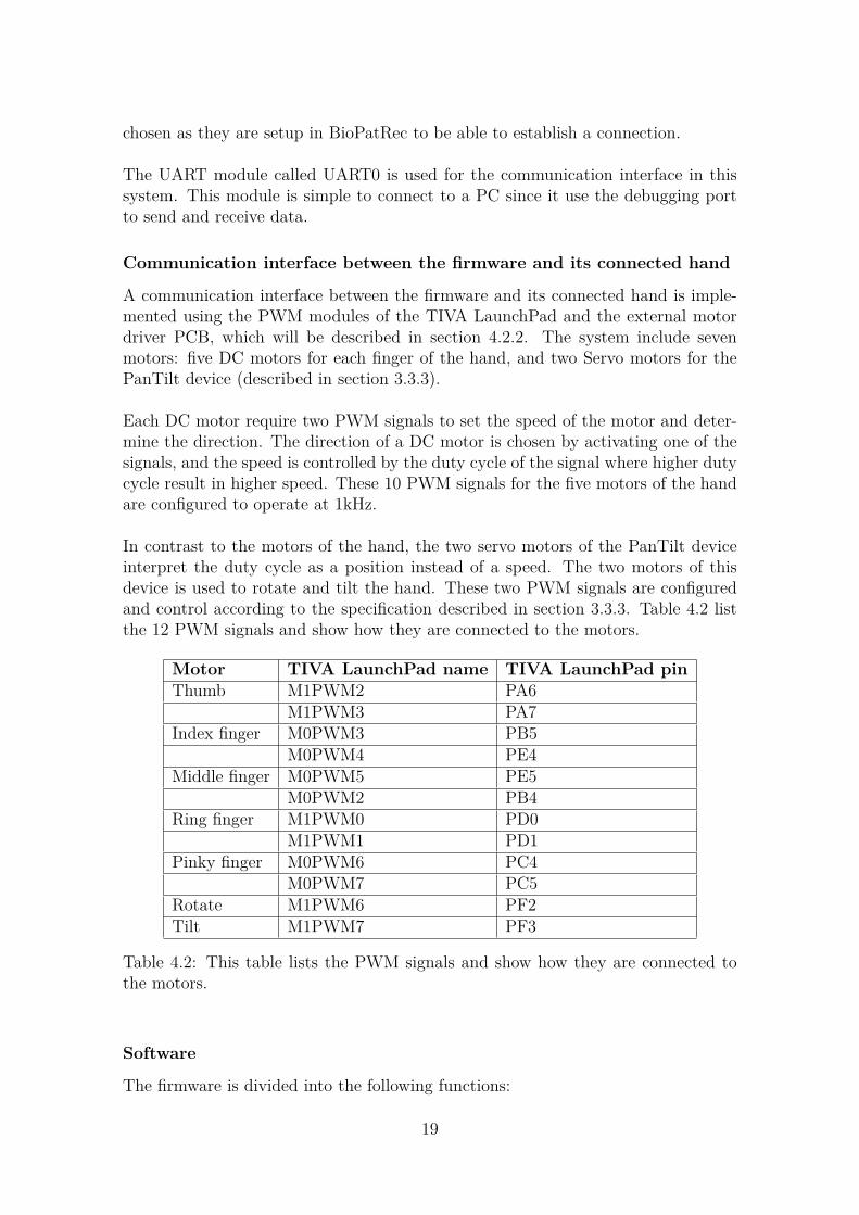
In contrast to the motors of the hand, the two servo motors of the PanTilt deviceinterpret the duty cycle as a position instead of a speed. The two motors of thisdevice is used to rotate and tilt the hand. These two PWM signals are configuredand control according to the specification described in section 3.3.3. Table 4.2 listthe 12 PWM signals and show how they are connected to the motors.
Motor TIVA LaunchPad name TIVA LaunchPad pinThumb M1PWM2 PA6
M1PWM3 PA7Index finger M0PWM3 PB5
M0PWM4 PE4Middle finger M0PWM5 PE5
M0PWM2 PB4Ring finger M1PWM0 PD0
M1PWM1 PD1Pinky finger M0PWM6 PC4
M0PWM7 PC5Rotate M1PWM6 PF2Tilt M1PWM7 PF3
Table 4.2: This table lists the PWM signals and show how they are connected tothe motors.
Software
The firmware is divided into the following functions:
19

• main(): The main function.
• initPWM(): This function initialize the PWM modules.
• initConsole(): This function initialize the UART module that is used for com-munication with a test GUI or BioPatRec.
• UARTIntHandler(): This function handles the interrupts that are triggeredby receiving data on the UART.
• handleData(): This function handles the data from the UART to control thePWM signals that are connected to the motors.
Fig 4.6 shows how the functions are structured and connected to each other.
Figure 4.6: This figure show how each function of the firmware is used and howthey depend on each other. The function main() initialize the modules by callingthe functions initPWM() and initConsole(). The function UARTIntHandles() cap-ture the data that is received from the UARt and send it to the function calledhandleData().
4.2.2 PCB for motor controlA PCB was made to combine all the external circuitry that is used to drive themotors into a common board. This PCB was designed to be connected on top if theTIVA LaunchPad as a TIVA BoosterPack [17]. It consists of three motor drivers,two voltage regulators and connectors to the hand. Fig 4.7 show the layout of thisPCB where the red figure is the top layer and the blue is the bottom layer.
The components to the right named OUTA,OUTB,OUTC in the red figure are theconnectors for the DC motors of the hand. The components in the upper right inthe same figure with the label S1 and S2 are the connectors for the servo motors.Table 4.3 show the connections between the PCB and the motors.
20

Figure 4.7: These figures shows the layout of the PCB design. The red layout is thetop layer and the blue layout is the bottom layer.
Motor BoosterPack connectorThumb OUTBIndex finger OUTAMiddle finger OUTARing finger OUTCPinky finger OUTCRotate S1Tilt S2
Table 4.3: This table lists the the connections between the motors and the PCBconnectors.
As in the original setup, the DRV8833 [23] motor driver chip was chosen. Each ofthese drivers are able to drive up to two DC motors.
The DC motors of the hand have different voltage requirements: the motors forthe thumb, index finger and middle finger require 4.5V, while the other two fingersrequire 3V. Instead of using two separate power supplies as in the original setup, twovoltage regulators was implemented to regulate a common external voltage source.
4.2.3 Communication interface between BioPatRec and theFirmware
When a UART connection is established between a PC and the firmware; this sys-tem communicate with three different types of messages. As in the system for theOttobock hands, each message start with an identifier to determine what functionthat should be performed. Depending on the type of the message, more parametersmay follow after the id.
21

• ‘C’: The message with this id is used to test the connection. The PC send thecharacter ‘C’ and the firmware, upon successful connection, acknowledge theconnection by responding with 0x1.
• ‘D’: The motor control of the DC motors of the hand are performed by sendinga message with this id from the PC. In addition to the id, this message includethree more parameters: motor index, speed value 1, and speed value 2. Themotor index is used to determine which motor to control. The two speedvariables are used to, as the name indicate, set the speed of the selected motor.Two speed variables are used to determine the direction of the motor. Thefirmware acknowledge receiving this message by responding with 0x1.
• ‘S’: The motor control of the Servo motors of the PanTilt device are per-formed by sending a message with this id from the PC. In addition to the id,this message include two more parameters: motor index and position. Thefirmware acknowledge receiving this message by responding with 0x1.
4.2.4 Test GUIsThe system was design to be compatible with the two test MATLAB GUIs from theoriginal interface. One GUI is used for the DC motors of the hand, and the other isused for the servo motors of the PanTilt device. They both share the same functionsto set up a connection to the firmware. Then each motor is controlled individuallyusing the buttons to sent different control commands. Fig 4.8 show these GUIs.
Figure 4.8: These figures shows the two GUIs that are used to control the motors.The GUI to the left control the DC motors and the GUI to the right control theservo motors.
The GUI for the DC motors of the hand have two parameters that is used to de-termine the speed and duration of the selected movement. The parameter “Speed”determine the speed of the motor and the parameter “Length” determine the dura-tion the selected motor will be active.
22
The GUI for the Servo motors can control the angle of the motor step-wise ordirectly. The parameter “Step” is used to determine the distance each step resultin. The boxes with the label “Position” change the motors directly according to theentered value. The buttons with the label “Center” return the motor to its startingposition.
4.3 A proposed standardised interfacing frame-work
The two previously described systems, that were developed in this work, differ indesign due to different requirements from the hand considered for each system.It is expected that the control signals of the firmware differ since the systems areimplemented considering its connected hand. However, the communication interfacebetween BioPatRec and the firmware can be improved with a common protocol.With this is mind, we created a framework which specify a standard on how tointerface a motor driven device with BioPatRec. This framework guide developershow to define their devices in BioPatRec and guide the development of the controlfirmware.
4.3.1 Defining a new deviceMovements and how each motor is used in each movement need to be defined wheninterfacing a new device. This is achieved using two ".def" files in BioPatRec: onethat lists the motors ("motors.def") of the device, and another that lists the move-ments ("movements.def") that the device can perform. A third ".def" file ("sen-sors.def") is used if the device is equipped with sensors.
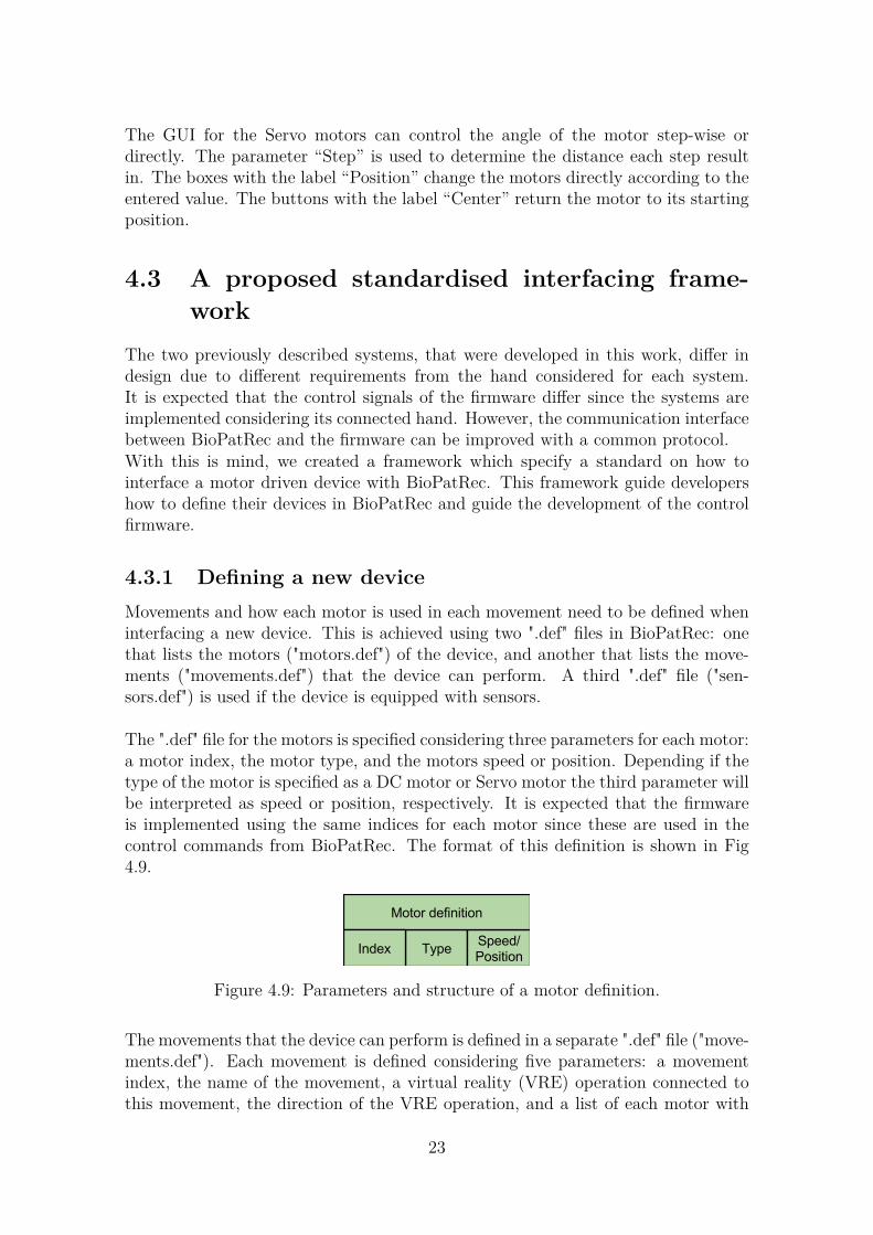
The ".def" file for the motors is specified considering three parameters for each motor:a motor index, the motor type, and the motors speed or position. Depending if thetype of the motor is specified as a DC motor or Servo motor the third parameter willbe interpreted as speed or position, respectively. It is expected that the firmwareis implemented using the same indices for each motor since these are used in thecontrol commands from BioPatRec. The format of this definition is shown in Fig4.9.
Figure 4.9: Parameters and structure of a motor definition.
The movements that the device can perform is defined in a separate ".def" file ("move-ments.def"). Each movement is defined considering five parameters: a movementindex, the name of the movement, a virtual reality (VRE) operation connected tothis movement, the direction of the VRE operation, and a list of each motor with
23
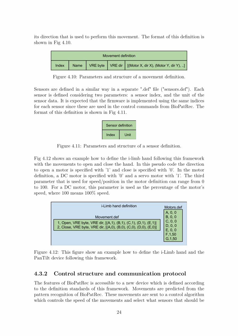
its direction that is used to perform this movement. The format of this definition isshown in Fig 4.10.
Figure 4.10: Parameters and structure of a movement definition.
Sensors are defined in a similar way in a separate ".def" file ("sensors.def"). Eachsensor is defined considering two parameters: a sensor index, and the unit of thesensor data. It is expected that the firmware is implemented using the same indicesfor each sensor since these are used in the control commands from BioPatRec. Theformat of this definition is shown in Fig 4.11.
Figure 4.11: Parameters and structure of a sensor definition.
Fig 4.12 shows an example how to define the i-limb hand following this frameworkwith the movements to open and close the hand. In this pseudo code the directionto open a motor is specified with ’1’ and close is specified with ’0’. In the motordefinition, a DC motor is specified with ’0’ and a servo motor with ’1’. The thirdparameter that is used for speed/position in the motor definition can range from 0to 100. For a DC motor, this parameter is used as the percentage of the motor’sspeed, where 100 means 100% speed.
Figure 4.12: This figure show an example how to define the i-Limb hand and thePanTilt device following this framework.
4.3.2 Control structure and communication protocolThe features of BioPatRec is accessible to a new device which is defined accordingto the definition standards of this framework. Movements are predicted from thepattern recognition of BioPatRec. These movements are sent to a control algorithmwhich controls the speed of the movements and select what sensors that should be
24
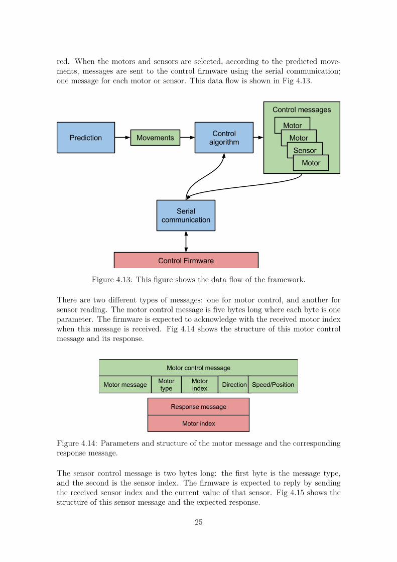
red. When the motors and sensors are selected, according to the predicted move-ments, messages are sent to the control firmware using the serial communication;one message for each motor or sensor. This data flow is shown in Fig 4.13.
Figure 4.13: This figure shows the data flow of the framework.
There are two different types of messages: one for motor control, and another forsensor reading. The motor control message is five bytes long where each byte is oneparameter. The firmware is expected to acknowledge with the received motor indexwhen this message is received. Fig 4.14 shows the structure of this motor controlmessage and its response.
Figure 4.14: Parameters and structure of the motor message and the correspondingresponse message.
The sensor control message is two bytes long: the first byte is the message type,and the second is the sensor index. The firmware is expected to reply by sendingthe received sensor index and the current value of that sensor. Fig 4.15 shows thestructure of this sensor message and the expected response.
25

Figure 4.15: Parameters and structure of the sensor message and the correspondingresponse message.
26

5Results
All the goals, presented in section 1.2, for each of the two systems are achieved.Three parameters were considered when evaluating each system: execution time,power consumption, and functionality. This chapter present these parameters ofeach of the two systems.
5.1 The system for the MyoHand VariPlus Speedand the SensorHand Speed
The control interface for the MyoHand VariPlus Speed and the SensorHand Speedachieve real-time control of the connected hand using either BioPatRec or a testGUI. The system is implemented to control the hand using 100 different speeds toopen or close the hand. The feedback signal, that is intended to be connected tothe user, can be generated at 90 different frequencies up to 10Hz. As described insection 3.3, these hands only feature one DoF. Therefore, simultaneous movementscannot be evaluated.
The execution time from sending a control command to receiving the response wasmeasured from 10 samples resulting in a mean value of 6.40ms. Changing the speedand duration parameters had no effect on this execution time.
The method described in section 2.6.4, was used to measure the power consumptionof the control unit and its connected hand. Two states of the system was tested: idleand operating. The current drawn by the system in the idle state was measured to51mA. The current drawn was measured to approximately 400mA when operatingthe hand by closing or opening it. A 7.4V 2200mAh battery was used as the powersource. This results in the system consuming 0.38W and 2.96W in the two statesrespectively. Table 5.1 shows these results.
System latency 6.40msPower consumption: idle state 0.38WPower consumption: operating state 2.96W
Table 5.1: This table shows the results of the interface system for the Ottobockhands.
27
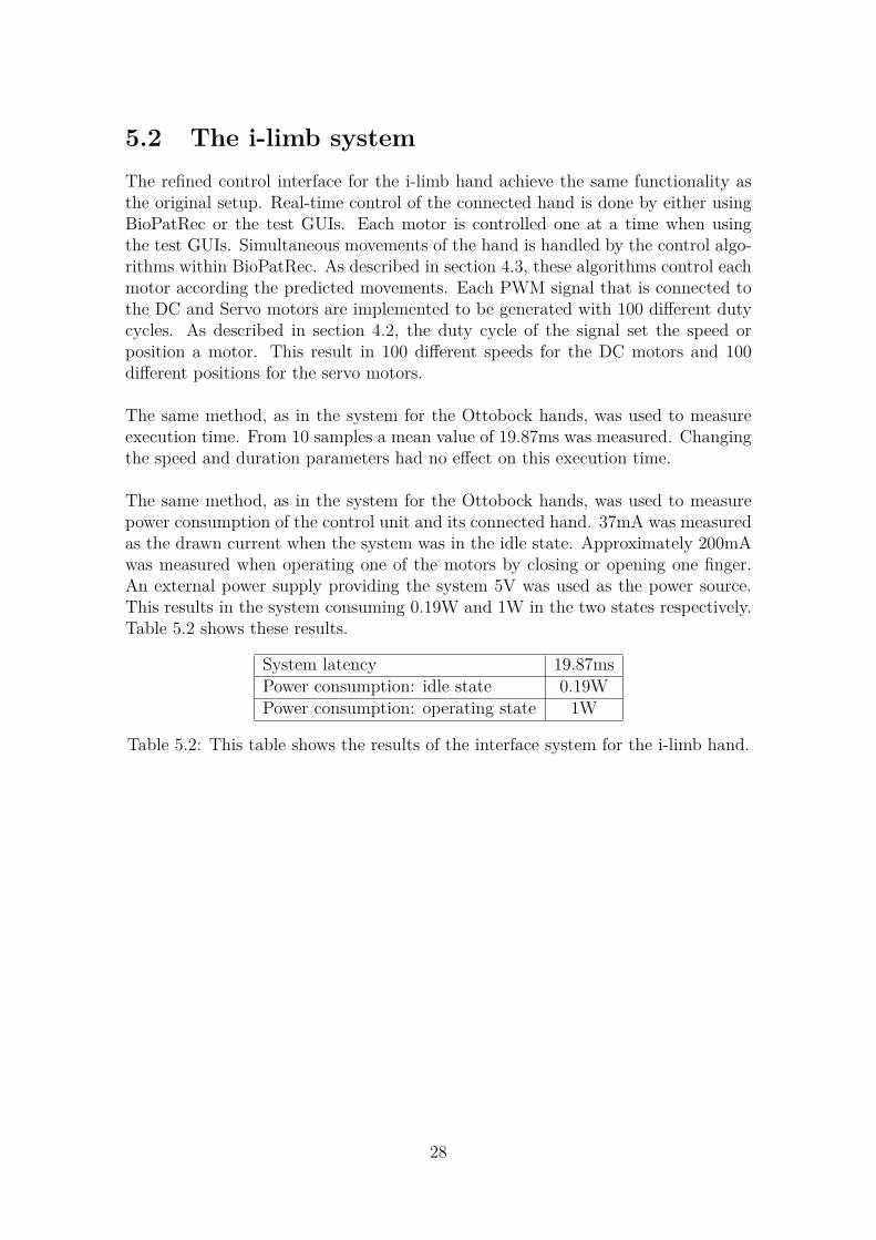
5.2 The i-limb systemThe refined control interface for the i-limb hand achieve the same functionality asthe original setup. Real-time control of the connected hand is done by either usingBioPatRec or the test GUIs. Each motor is controlled one at a time when usingthe test GUIs. Simultaneous movements of the hand is handled by the control algo-rithms within BioPatRec. As described in section 4.3, these algorithms control eachmotor according the predicted movements. Each PWM signal that is connected tothe DC and Servo motors are implemented to be generated with 100 different dutycycles. As described in section 4.2, the duty cycle of the signal set the speed orposition a motor. This result in 100 different speeds for the DC motors and 100different positions for the servo motors.
The same method, as in the system for the Ottobock hands, was used to measureexecution time. From 10 samples a mean value of 19.87ms was measured. Changingthe speed and duration parameters had no effect on this execution time.
The same method, as in the system for the Ottobock hands, was used to measurepower consumption of the control unit and its connected hand. 37mA was measuredas the drawn current when the system was in the idle state. Approximately 200mAwas measured when operating one of the motors by closing or opening one finger.An external power supply providing the system 5V was used as the power source.This results in the system consuming 0.19W and 1W in the two states respectively.Table 5.2 shows these results.
System latency 19.87msPower consumption: idle state 0.19WPower consumption: operating state 1W
Table 5.2: This table shows the results of the interface system for the i-limb hand.
28

6Discussion
In this chapter, improvements, trade-offs, and the results of the two systems willbe discussed and evaluated with the previous sections as reference. In addition, theproposed framework and its importance for future work is also evaluated.
6.1 System latency and Power consumption of theMyoHand VariPlus Speed and the SensorHandSpeed
The priority when we implemented both control system was to achieve the intendedfunctionality using a digital control platform. Although we manage to achieve thisfunctionality we did not optimize for power efficiency. There are several parametersthat affect both power consumption and performance of the systems. The questionis: where it is beneficial to increase performance and what impact on the powerconsumption would the change have? For instance, the clock frequency of the TIVALaunchPad was reduced from the maximum value of 80MHz, which is the standardconfiguration, to 1MHz. This was done to simplify calculations of the other mod-ules and be able to use functions that may give strange results at high frequencies.This parameter may attract to gain more performance. However, is the performanceof calculations on the TIVA LaunchPad platform the bottleneck of the system? Iwould say probably not; since only a handful of arithmetic operations are needed totranslate the received control command to change the control signal of each motor.It is more likely that the communication interface and prediction of the movementsdominate the performance of the system.
Although the presented system latency of 6.40ms and 19.87ms for the system of theOttobock hands and the system for the i-limb hand respectively seem promising;there are other parts that need to be considered in an actual field test. Patternrecognition and other more advanced components are expected to affect the perfor-mance.
The measured idle drawn current of each system is acceptable. Robotic hand pros-theses are usually driven by a battery with a capacity of 2200mAh. Consideringsuch battery as the power source for theses systems it would result in an estimatedidle life time of 30h and 40h for the system of the Ottobock hands and the systemfor the i-limb hand respectively.
29
The PCB including the motor drivers for the i-limb system was first design to usethe 5V power source directly from the TIVA LaunchPad. This source turned outnot to be able to provide enough current to certain motors of the hand. Therefore,the PCB was redesigned to use an external source instead. As mentioned in thedescription of the design and implementation, the motors of the i-limb hand requiretwo different voltage levels, 4.5V and 3V, where two regulators are used to regulatethe input voltage to these levels. The latest design still use two regulators andrequire the input voltage to be greater or equal to the highest output voltage, whichis 4.5V in this design. This can be further improved; one of the regulators canbe removed, since the PCB is not limited of the voltage levels from the connectedTIVA LaunchPad anymore. This improvement would reduce approximately ¼ ofthe components of the PCB which would result in less power consumption. However,this improvement was discovered late in the project and is therefore not implementedbecause of limited time.
6.2 The proposed standardised interfacing frame-work
After developing two control interfaces with BioPatRec we realised that a standard-ized method would be useful. The purpose of the interface framework is to guidedevelopers to interface with BioPatRec and also guide the implementation of thecorresponding firmware. A new device is simply defined by following the movement,motor and sensor structures; instead of implementing separate control functions asa definition is made in the current version.
Separate control functions implemented in a high level language, with a tool suchas MATLAB, may simplify the control logic of the firmware. This is often the casepreferable when developing a system. However, since BioPatRec is meant to beused for many different kind of motor devices this structure would grow more andmore complex as more devices are added to the platform. Therefore, we decidedto create this framework to standardise the interface to BioPatRec as one commonstructure that only consider the motors and sensors of the connected device. Allcontrol functionality is instead guided to be implemented in the firmware using thedata from this interface.
Another benefit of using the framework is that functionality of individual and simul-taneous movements are ensured. The prediction mechanisms and control algorithmsof BioPatRec determine which movements to perform and is able to activate the mo-tors of the connected device accordingly by using the motor definition of the selectedmovements.
30
6.3 Future developmentThe two prototype systems developed in this project are both implemented for test-ing purposes to elaborate digital control of robotic hand prostheses. The first thingto improve, if continuing with this project, would be to modify the two systems ac-cording to the proposed framework. In the current versions, this is not implementedbecause the framework was developed based on the complexity that was discoveredafter designing the two control systems.
Further future development of similar systems might be interested in integrating thecontrol system into a single product. To achieve this, BioPatRec would need to beportable so it can be implemented on a stand-alone device. In the current version,BioPatRec has many configurable options which are setup using the various GUIs. Ithink it would be useful to use a similar structure to configure a hardware platformwhere each function of the platform have a corresponding pre-defined hardwareblock. The configuration of the platform can then be programmed to some externalhardware, for example an FPGA, using these blocks. In addition, the firmware forthe device to be controlled would need to be implemented on the same hardware.At last, this hardware consisting of the BioPatRec configuration and the controlfirmware would need to be integrated with the device.
31

7Conclusion
A hand prosthesis is an artificial device that is used as an replacement for a losthand. A highly desirable feature for the control of artificial hand limbs is predictionof simultaneous motions. State-of-the-art control of such devices is done by usinga simple threshold technique; one output from one input. Two input signals arenecessary to control the two directions of one DoF, and to switch between differentpredefined functions either co-contraction or a physical switch is used. However,this serial operation is unnatural and slow.
The purpose of this project was to develop advanced control systems for high-endprosthetic devices with the pattern recognition platform BioPatRec to allow moresophisticated control schemes. Electronics, PCB design and communication proto-cols are areas involved when developing these systems.
Two systems considering three different hands was developed. One system for theMyoHand VariPlus Speed [10] or the SensorHand Speed [11] from Ottobock, andanother for the i-limb [4] hand from Touch Bionics. Both systems achieve accept-able performance with a system latency of 6.40ms for the system considering theOttobock hands and 19.87ms for the system considering the i-limb hand. A 7.4V2200mAh battery is commonly used as the power source for robotic hand prostheses.If a source with this capacity is used for each of these control systems; they are bothestimated to be operational longer than a day.
Creating an interface between BioPatRec and a control unit require specific functionson both sides to achieve a control system. After developing the two systems in thisproject we discovered that interfacing more devices became more and more complexon the software side. To address this, a proposed framework was developed tospecify a standard on how to interface a motor driven device with BioPatRec. Thisframework guide developers how to define their devices in BioPatRec and guide thedevelopment of the control firmware.
32
Bibliography
[1] M. Ortiz-Catalan, B. Hakansson, and R. Branemark, “Real-time and simultane-ous control of artificial limbs based on pattern recognition algorithms,” NeuralSystems and Rehabilitation Engineering, vol. 22, no. 4, pp. 756–764, 2014.
[2] D. J. Atkins, D. C. Heard, and W. H. Donovan, “Epidemiologic overview ofindividuals with upper-limb loss and their reported research priorities.” JPO:Journal of Prosthetics and Orthotics, vol. 8, no. 1, pp. 2–11, 1996.
[3] C. Cipriani, M. Controzzi, and M. C. Carrozza, “The smarthand transradialprosthesis,” Journal of neuroengineering and rehabilitation, vol. 8, no. 1, p. 29,2011.
[4] Touch Bionics. Technology that touches lives. [Online]. Available:http://www.touchbionics.com/products/active-prostheses/i-limb-ultra
[5] RSL Steeper. The BeBionic hand - independence through technology. [Online].Available: http://bebionic.com/the_hand
[6] Ottobock. The Michelangelo hand. [Online]. Available:http://professionals.ottobockus.com/cps/rde/xchg/ob_us_en/hs.xsl/49490.html
[7] Vincent systems. The touch sensing hand prosthesis of the next generation. [On-line]. Available: http://vincentsystems.de/en/prosthetics/vincent-evolution-2/
[8] Prensilia. Self-contained robotic hands. [Online]. Available:http://www.prensilia.com/index.php?q=en/node/40
[9] M. Ortiz-Catalan, R. Brånemark, and B. Håkansson, “Biopatrec: A modularresearch platform for the control of artificial limbs based on pattern recognitionalgorithms.” Source code for biology and medicine, vol. 8, no. 11, 2013.
[10] Ottobock. Myohand variplus speed. [Online]. Available:http://www.ottobock.com/cps/rde/xchg/ob_com_en/hs.xsl/19992.html
[11] ——. Sensorhand speed. [Online]. Available:http://www.ottobock.com/cps/rde/xchg/ob_com_en/hs.xsl/3652.html
[12] MathWorks. The language of technical computing. [Online]. Available:http://se.mathworks.com/products/matlab/whatsnew.html?s_tid=tb_14b
33

[13] ——. Matlab gui. [Online]. Available:http://se.mathworks.com/discovery/matlab-gui.html
[14] Texas Instruments. Tiva c series launchpad evaluation kit. [Online]. Available:http://www.ti.com/tool/ek-tm4c123gxl
[15] ——. Code composer studio (CCS) integrated development environment(IDE). [Online]. Available: http://www.ti.com/tool/ccstudio
[16] CadSoft. Eagle pcb design software. [Online]. Available:http://www.cadsoftusa.com/
[17] Texas Instruments. Boosterpacks - plug-in modules. [Online]. Available:http://www.ti.com/ww/en/launchpad/boosterpacks.html
[18] M. Ortiz-Catalan. Biopatrec. [Online]. Available:https://code.google.com/p/biopatrec/wiki/BioPatRec
[19] E. Scheme and K. Englehart, “Electromyogram pattern recognition for controlof powered upper-limb prostheses: State of the art and challenges for clinicaluse,” Journal of Rehabilitation Research & Development, vol. 48, no. 6, p. 643,2011.
[20] A. Osborne, “An introduction to microcomputers,” 1976.
[21] SERVOCITY. Hs-5955tg servo. [Online]. Available:https://www.servocity.com/html/hs7955tg_servo.html#.VWHMOE_tlBf
[22] Texas Instruments. F28069 Piccolo controlCARD. [Online]. Available:http://www.ti.com/tool/tmdscncd28069
[23] ——. Drv8833: 2A low voltage dual brushed dc or single bipolar stepper motordriver (PWM ctrl). [Online]. Available: http://www.ti.com/product/drv8833
34