comos platform interfaces - siemens · pdf filecomos platform comos platform interfaces...
TRANSCRIPT

COMOS
PlatformCOMOS Platform Interfaces
Operating Manual
11/2013A5E32019975-AA
Importing and exporting data 1
XML connectors 2
Standard import "Blank XML" 3
Standard import "Blank table" 4
Engineering projects 5
Data exchange with NOXIE 6
COMOS document interface 7
SAP interface 8
Interface to Teamcenter 9

Legal informationWarning notice system
This manual contains notices you have to observe in order to ensure your personal safety, as well as to prevent damage to property. The notices referring to your personal safety are highlighted in the manual by a safety alert symbol, notices referring only to property damage have no safety alert symbol. These notices shown below are graded according to the degree of danger.
DANGER
indicates that death or severe personal injury will result if proper precautions are not taken.
WARNING
indicates that death or severe personal injury may result if proper precautions are not taken.
CAUTION
indicates that minor personal injury can result if proper precautions are not taken.
NOTICEindicates that property damage can result if proper precautions are not taken.If more than one degree of danger is present, the warning notice representing the highest degree of danger will be used. A notice warning of injury to persons with a safety alert symbol may also include a warning relating to property damage.
Qualified PersonnelThe product/system described in this documentation may be operated only by personnel qualified for the specific task in accordance with the relevant documentation, in particular its warning notices and safety instructions. Qualified personnel are those who, based on their training and experience, are capable of identifying risks and avoiding potential hazards when working with these products/systems.
Proper use of Siemens productsNote the following:
WARNING
Siemens products may only be used for the applications described in the catalog and in the relevant technical documentation. If products and components from other manufacturers are used, these must be recommended or approved by Siemens. Proper transport, storage, installation, assembly, commissioning, operation and maintenance are required to ensure that the products operate safely and without any problems. The permissible ambient conditions must be complied with. The information in the relevant documentation must be observed.
TrademarksAll names identified by ® are registered trademarks of Siemens AG. The remaining trademarks in this publication may be trademarks whose use by third parties for their own purposes could violate the rights of the owner.
Disclaimer of LiabilityWe have reviewed the contents of this publication to ensure consistency with the hardware and software described. Since variance cannot be precluded entirely, we cannot guarantee full consistency. However, the information in this publication is reviewed regularly and any necessary corrections are included in subsequent editions.
Siemens AGIndustry SectorPostfach 48 4890026 NÜRNBERGGERMANY
A5E32019975-AAⓅ 10/2013 Technical data subject to change
Copyright © Siemens AG 2013.All rights reserved

Table of contents
1 Importing and exporting data......................................................................................................................11 1.1 Reimporting content of Access/Excel/XML files..........................................................................11 1.1.1 Introduction..................................................................................................................................11 1.1.2 Reading data into queries...........................................................................................................11 1.1.3 Preparing read data for reimport.................................................................................................12 1.1.4 Status values...............................................................................................................................12 1.1.5 Carry out the reimport.................................................................................................................13 1.1.6 Error messages...........................................................................................................................13 1.2 Reimporting content of Access/Excel files or directories.............................................................14 1.2.1 Introduction..................................................................................................................................14 1.2.2 Reimporting a file........................................................................................................................14 1.2.3 Reimporting a directory...............................................................................................................15 1.3 Exporting a report as a PDF........................................................................................................15 1.4 Exporting reports to Excel...........................................................................................................16 1.4.1 Introduction..................................................................................................................................16 1.4.2 Exporting an individual report......................................................................................................17 1.4.3 Exporting multiple reports............................................................................................................17 1.4.4 Using the report in Excel.............................................................................................................18 1.4.5 Configuration via a script.............................................................................................................18 1.4.5.1 Control via the options script.......................................................................................................18 1.4.5.2 Reimport......................................................................................................................................20 1.5 Exporting reports to Word...........................................................................................................20 1.5.1 Introduction..................................................................................................................................20 1.5.2 Exporting an individual report......................................................................................................20 1.5.3 Exporting multiple reports............................................................................................................21 1.6 Exporting and importing DWG/DXF files.....................................................................................21 1.6.1 Displaying AutoCAD files............................................................................................................21 1.6.1.1 Introduction..................................................................................................................................21 1.6.1.2 Displaying an AutoCAD file as an external document.................................................................22 1.6.1.3 Displaying an AutoCAD file as a PQM document.......................................................................22 1.6.1.4 Displaying an AutoCAD file as an external drawing in a report...................................................22 1.6.2 Exporting AutoCAD data.............................................................................................................23 1.6.2.1 Scope of the interface ................................................................................................................23 1.6.2.2 Exporting an individual report......................................................................................................25 1.6.2.3 Exporting multiple reports............................................................................................................25 1.6.3 Importing AutoCAD data.............................................................................................................26 1.6.3.1 Overview.....................................................................................................................................26 1.6.3.2 Scope of the interface.................................................................................................................26 1.6.3.3 Importing an AutoCAD drawing in an interactive report..............................................................28 1.6.3.4 Importing an AutoCAD drawing as a symbol for a base object...................................................28 1.6.3.5 Dissolving an AutoCAD object into engineering objects.............................................................28 1.6.3.6 Dissolving an AutoCAD object graphically..................................................................................29 1.6.3.7 Analyzing a DWG/DXF drawing..................................................................................................30
COMOS Platform InterfacesOperating Manual, 11/2013, A5E32019975-AA 3

1.6.3.8 Viewing information about the AutoCAD object..........................................................................30 1.6.3.9 Information about embedded AutoCAD object in the properties.................................................31 1.6.3.10 Referencing of XRefs during the import operation now suppressed...........................................31 1.6.3.11 Improving the text display of a DXF file.......................................................................................31 1.6.4 Configuring mapping of DWG data.............................................................................................32 1.6.4.1 DWG/DXF mapping editor...........................................................................................................32 1.6.4.2 Opening the DWG/DXF mapping editor......................................................................................32 1.6.4.3 Defining an entry.........................................................................................................................32 1.6.5 Other import settings...................................................................................................................33 1.6.6 Central base data branch for DXF imports..................................................................................33 1.6.7 Adjustments for the import .........................................................................................................34 1.7 User interface..............................................................................................................................35 1.7.1 "Access/Excel/XML reimport" tab................................................................................................35 1.7.2 "Reimport" tab.............................................................................................................................35 1.7.3 "Report to Excel" window............................................................................................................36 1.7.4 "Report to Word" window............................................................................................................37 1.7.5 "Report to DWG/DXF" window....................................................................................................37 1.7.6 "Dissolve DWG/DXF drawing into engineering objects" window.................................................38 1.7.7 Tabs in the mapping editor..........................................................................................................38 1.7.7.1 "General" tab...............................................................................................................................38 1.7.7.2 "Line types" tab...........................................................................................................................40 1.7.7.3 "Colors" tab.................................................................................................................................41 1.7.7.4 "Layer" tab...................................................................................................................................41 1.7.7.5 "Combinations" tab......................................................................................................................41
2 XML connectors..........................................................................................................................................43 2.1 Basic principles...........................................................................................................................43 2.1.1 Introduction..................................................................................................................................43 2.1.2 Requirement................................................................................................................................44 2.1.3 Basic concept of data mapping...................................................................................................44 2.1.4 Maintaining old connectors prior to version 9.0...........................................................................44 2.1.5 Connector document...................................................................................................................44 2.1.6 Connector template.....................................................................................................................45 2.1.7 Basic principle of XML connectors..............................................................................................45 2.1.8 "Envelope" field...........................................................................................................................46 2.1.9 Supported codes ........................................................................................................................47 2.2 XML connector documents..........................................................................................................47 2.2.1 Creating an XML connector document........................................................................................47 2.2.2 Opening the configuration tool....................................................................................................47 2.2.3 Configuration of queries..............................................................................................................48 2.2.4 Reusing queries..........................................................................................................................48 2.2.5 Assigning a query using properties.............................................................................................49 2.2.6 Drag&drop assignment................................................................................................................49 2.2.7 Creating objects with different base objects via a query.............................................................50 2.2.8 References..................................................................................................................................51 2.2.9 Configuring references in the XML connector.............................................................................52 2.2.10 Examples of XML mapping.........................................................................................................53 2.2.11 COMOS Collection (REFID)........................................................................................................54 2.2.12 Defining the COMOS collection...................................................................................................55 2.2.13 Mapping table for values.............................................................................................................55 2.2.14 Transforming data during runtime...............................................................................................56
Table of contents
COMOS Platform Interfaces4 Operating Manual, 11/2013, A5E32019975-AA

2.2.15 "COMOS info" column.................................................................................................................56 2.2.16 Check column..............................................................................................................................57 2.2.17 XML fragments (XFRAG)............................................................................................................57 2.2.18 Creating an XML fragment..........................................................................................................58 2.2.19 Connecting a query with XML connector.....................................................................................58 2.2.20 Column properties.......................................................................................................................59 2.2.21 Direct help in the configuration tool.............................................................................................60 2.3 Configuring the export of XML data.............................................................................................60 2.3.1 Basic principles...........................................................................................................................60 2.3.2 Assignments in the "XML mapping" column................................................................................61 2.3.3 Comparing XML data and COMOS data.....................................................................................61 2.3.4 Nested queries............................................................................................................................62 2.4 Configuring the import of XML data.............................................................................................64 2.4.1 Key columns................................................................................................................................64 2.4.2 Master column ............................................................................................................................65 2.4.3 Expressions supported for the import..........................................................................................65 2.5 Using XML connectors................................................................................................................65 2.5.1 Exporting COMOS data...............................................................................................................65 2.5.2 Importing COMOS data...............................................................................................................65 2.5.3 Progress bar................................................................................................................................66 2.5.4 XML adapter................................................................................................................................66 2.5.5 Triggering connectors via a script ..............................................................................................67 2.6 Extending an XML connector through a C# assembly................................................................69 2.6.1 Connector expansion for C# assemblies.....................................................................................69 2.6.2 Creating a new C# assembly......................................................................................................69 2.6.3 Loading existing assemblies.......................................................................................................70 2.6.4 Class documentation...................................................................................................................70 2.6.5 "ICodeProviderActions" interface................................................................................................71 2.6.6 "IAdapterActions" interface..........................................................................................................72 2.6.7 "IJobHelper" interface..................................................................................................................73 2.6.8 "IXMLExecJob" interface.............................................................................................................74 2.6.9 "Preprocessing/postprocessing" adapter....................................................................................74 2.6.10 "Custom" adapter type................................................................................................................75 2.7 User interface..............................................................................................................................75 2.7.1 General control elements of the configuration tool......................................................................75 2.7.2 "COMOS" tab..............................................................................................................................76 2.7.3 "XML" tab....................................................................................................................................76 2.7.4 "Mapping" tab..............................................................................................................................76 2.7.5 "Assembly" tab............................................................................................................................77 2.7.6 "Error" tab....................................................................................................................................78 2.7.7 "Extras" tab of the column properties..........................................................................................78 2.7.8 "Script" tab...................................................................................................................................80 2.7.9 "Extras" tab of the column properties..........................................................................................83 2.7.10 "MotionX" window for the export.................................................................................................83 2.7.11 "MotionX" window for the import.................................................................................................83
3 Standard import "Blank XML".....................................................................................................................85 3.1 Introduction..................................................................................................................................85 3.2 Opening the preset standard import............................................................................................85
Table of contents
COMOS Platform InterfacesOperating Manual, 11/2013, A5E32019975-AA 5

3.3 Creating a new standard import..................................................................................................85 3.4 Configuring and carrying out a standard import..........................................................................86 3.5 Using saved settings for the import.............................................................................................86 3.6 Allowing or prohibiting changes to import settings......................................................................87
4 Standard import "Blank table".....................................................................................................................89 4.1 Introduction..................................................................................................................................89 4.2 Opening the preset standard import............................................................................................89 4.3 Creating a new standard import..................................................................................................90 4.4 Configuring and carrying out a standard import..........................................................................90 4.5 Using saved settings for the import.............................................................................................91 4.6 Properties of an action object......................................................................................................91 4.7 Import sources.............................................................................................................................91 4.7.1 Access.........................................................................................................................................91 4.7.2 Excel............................................................................................................................................92 4.7.3 Text file........................................................................................................................................92 4.8 Script for import actions...............................................................................................................93 4.8.1 Import script.................................................................................................................................93 4.8.2 Script blocks................................................................................................................................93 4.8.3 Applying a script component.......................................................................................................96 4.8.4 "Declarations" tab........................................................................................................................96 4.8.5 Example......................................................................................................................................96 4.9 Tab "Blank table".........................................................................................................................97
5 Engineering projects...................................................................................................................................99 5.1 Importing a project.......................................................................................................................99 5.2 Exporting a project......................................................................................................................99
6 Data exchange with NOXIE .....................................................................................................................101 6.1 Purpose of NOXIE.....................................................................................................................101 6.2 Exchanging data via the NOXIE plugin.....................................................................................101 6.3 Structure of the generated XML file ..........................................................................................103
7 COMOS document interface....................................................................................................................105 7.1 Introduction................................................................................................................................105 7.2 Requirements............................................................................................................................105 7.3 Using a COMOS document interface........................................................................................105 7.3.1 Creating an Office document.....................................................................................................106 7.3.2 Preparing Office documents......................................................................................................106 7.3.3 Working in the "Document Interface" tab..................................................................................107 7.3.4 Special features for Word..........................................................................................................110 7.3.5 Export........................................................................................................................................111 7.3.6 Reimport....................................................................................................................................112 7.3.7 Macros.......................................................................................................................................112
Table of contents
COMOS Platform Interfaces6 Operating Manual, 11/2013, A5E32019975-AA

7.4 Reference of the script functions...............................................................................................114 7.4.1 Reference of the programming interface...................................................................................114 7.4.2 Properties..................................................................................................................................114 7.4.3 Function: ExcelABC..................................................................................................................115 7.4.4 Function: Content......................................................................................................................115 7.4.5 Function: ContentFix.................................................................................................................116
8 SAP interface............................................................................................................................................119 8.1 Introduction................................................................................................................................119 8.2 Using the SAP interface............................................................................................................120 8.2.1 Requirements............................................................................................................................120 8.2.2 Exporting or importing SAP Business Objects..........................................................................120 8.3 Administering the SAP interface................................................................................................120 8.3.1 Requirements............................................................................................................................120 8.3.2 Architecture of the COMOS SAP Interface...............................................................................121 8.3.3 User and password management.............................................................................................122 8.3.3.1 SAP target systems...................................................................................................................122 8.3.3.2 Creating an SAP target system.................................................................................................123 8.3.3.3 Logging in to the SAP target system.........................................................................................123 8.3.3.4 Logging in to the SAP target system with a PKI card................................................................124 8.3.4 Checking the SAP interface configuration.................................................................................124 8.3.4.1 General......................................................................................................................................124 8.3.4.2 Opening the SAP interface configuration..................................................................................125 8.3.4.3 User interface of the SAP interface configuration.....................................................................126 8.3.4.4 Testing the SAP connection......................................................................................................126 8.3.4.5 Checking the XML connector configuration...............................................................................127 8.3.5 Configuring an SAP interface....................................................................................................130 8.3.5.1 General settings........................................................................................................................130 8.3.5.2 Create RFC objects...................................................................................................................130 8.3.5.3 Preparing SAP interface objects...............................................................................................131 8.3.5.4 Parameter types........................................................................................................................131 8.3.5.5 Linking SAP interface objects to COMOS objects.....................................................................132 8.3.5.6 Creating a SAP interface object as an element.........................................................................132 8.3.5.7 Creating a link...........................................................................................................................133 8.3.5.8 Preparing XML connectors........................................................................................................134 8.3.5.9 Configuring an XML connector..................................................................................................137 8.3.5.10 Establishing an SAP connection using the "saplogon.ini" file...................................................139 8.3.5.11 Displaying class characteristics from SAP in COMOS..............................................................139 8.3.5.12 Import and export settings for COMOS attributes.....................................................................142 8.3.6 XML schema for the data communication.................................................................................143 8.3.7 Deleting XML files after data communication............................................................................146 8.3.8 Configuring the SAP "Maintenance" module.............................................................................147 8.3.8.1 Introduction................................................................................................................................147 8.3.8.2 Functional locations...................................................................................................................147 8.3.8.3 Equipment.................................................................................................................................150 8.3.9 Configuring the SAP "Material management" module...............................................................152 8.3.9.1 Introduction................................................................................................................................152 8.3.9.2 Materials....................................................................................................................................152 8.3.9.3 Bills of materials........................................................................................................................155 8.3.10 Configuring the SAP "Documents" module...............................................................................157 8.3.10.1 Introduction................................................................................................................................157
Table of contents
COMOS Platform InterfacesOperating Manual, 11/2013, A5E32019975-AA 7

8.3.10.2 Workflow for exporting documents............................................................................................157 8.3.10.3 Preparing an RFC object...........................................................................................................157 8.3.10.4 Configuring an XML connector..................................................................................................158 8.3.10.5 Special settings on the "RFCs" tab of the RFC object..............................................................158 8.3.10.6 SAP interface objects................................................................................................................159 8.3.11 Importing the device catalog.....................................................................................................159 8.3.11.1 Introduction................................................................................................................................159 8.3.11.2 Defining an SAP catalog object.................................................................................................159 8.3.11.3 Defining a query........................................................................................................................160 8.3.11.4 Commands in the context menu of the column headers...........................................................161 8.3.11.5 Importing devices......................................................................................................................161 8.3.11.6 Assignment of XML data...........................................................................................................162 8.3.12 RFCs.........................................................................................................................................162 8.3.12.1 "RFCs" tab of the RFC object....................................................................................................162 8.3.12.2 Type mapping of the RFC object...............................................................................................162 8.3.12.3 Attributes of the RFC object......................................................................................................163 8.4 User interface............................................................................................................................165 8.4.1 "SAP login" tab..........................................................................................................................165 8.4.2 "Properties" window for the SAP target system........................................................................166 8.4.3 "General > XML" tab.................................................................................................................167 8.4.4 "SAP" tab...................................................................................................................................167
9 Interface to Teamcenter...........................................................................................................................171 9.1 COMOS Teamcenter interface..................................................................................................171 9.1.1 Introduction................................................................................................................................171 9.1.2 Terms........................................................................................................................................171 9.1.3 Transferring data from Teamcenter to COMOS........................................................................172 9.1.3.1 Basic principles.........................................................................................................................172 9.1.3.2 Mapping a unit from Teamcenter..............................................................................................172 9.1.3.3 Checking and making settings..................................................................................................173 9.1.3.4 Synchronizing a unit from Teamcenter......................................................................................174 9.1.4 Transferring data from COMOS to Teamcenter........................................................................174 9.1.4.1 Basic principles.........................................................................................................................174 9.1.4.2 Checking and making settings..................................................................................................175 9.1.4.3 Synchronizing a unit to Teamcenter..........................................................................................175 9.1.5 Publishing documents...............................................................................................................176 9.1.5.1 Checking settings......................................................................................................................176 9.1.5.2 Publishing documents...............................................................................................................176 9.1.6 Synchronizing attribute values..................................................................................................177 9.1.6.1 Static and dynamic data............................................................................................................177 9.1.6.2 Forms for static data..................................................................................................................178 9.1.6.3 Forms for dynamic data.............................................................................................................178 9.1.7 Changes in COMOS..................................................................................................................179 9.1.7.1 Creating a mapping object........................................................................................................179 9.1.7.2 Specifying the instance mapping...............................................................................................181 9.1.8 Configuring the interface to Teamcenter...................................................................................182 9.1.8.1 Overview...................................................................................................................................182 9.1.8.2 Workflow....................................................................................................................................183 9.1.8.3 Naming conventions..................................................................................................................184 9.1.8.4 Configuring Teamcenter............................................................................................................184 9.1.8.5 Setting Teamcenter options......................................................................................................185 9.1.8.6 Making changes in the "Default.xml" file...................................................................................186
Table of contents
COMOS Platform Interfaces8 Operating Manual, 11/2013, A5E32019975-AA

9.1.8.7 Configuring a project in Teamcenter.........................................................................................186 9.1.8.8 Specifying resources and types for the assignment..................................................................187 9.1.8.9 Creating an "Application Interface"............................................................................................188 9.1.8.10 Creating a "Collaboration Context" for an existing unit.............................................................189 9.1.8.11 Creating a "Collaboration Context" for synchronizing a plant from COMOS.............................190 9.1.9 Configuring COMOS.................................................................................................................190 9.1.9.1 Installing the buffer component for the COMOS client..............................................................190 9.1.9.2 Synchronizing resources...........................................................................................................191 9.1.9.3 Calling the properties of synchronized resources.....................................................................193 9.1.9.4 Assigning units of measurement...............................................................................................193 9.1.9.5 Assigning resources and types.................................................................................................194 9.1.9.6 Assigning attributes...................................................................................................................195 9.1.9.7 Synchronizing resource information..........................................................................................196 9.1.9.8 Preparations for publishing documents.....................................................................................197 9.1.10 User interface............................................................................................................................197 9.1.10.1 Status area in windows.............................................................................................................197 9.1.10.2 "Teamcenter login" window.......................................................................................................198 9.1.10.3 "Synchronize plant from Tc" window.........................................................................................199 9.1.10.4 "Synchronize plant to Tc" window.............................................................................................200 9.1.10.5 "Element properties" window.....................................................................................................200 9.1.10.6 "Select Tc resource" window.....................................................................................................201 9.1.10.7 "Element properties" window in the base objects .....................................................................201 9.1.10.8 "Synchronize resource info" window.........................................................................................202 9.1.10.9 "Teamcenter units of measurement" tab...................................................................................202 9.1.10.10 "CTI resource mapping" tab.................................................................................................202 9.1.10.11 "CTI attribute mapping" tab..................................................................................................203 9.1.10.12 "CTI instance mapping" tab..................................................................................................203 9.2 Process Data Interface (PDI)....................................................................................................204 9.2.1 Introduction................................................................................................................................204 9.2.2 Using PDI..................................................................................................................................204 9.2.2.1 Connection between COMOS and NX......................................................................................204 9.2.2.2 Exporting pipe specs to Teamcenter.........................................................................................204 9.2.2.3 Publishing documents...............................................................................................................205 9.2.2.4 Connecting COMOS and NX.....................................................................................................206 9.2.2.5 Disconnecting the connection between COMOS and NX.........................................................207 9.2.2.6 Assigning objects......................................................................................................................207 9.2.2.7 Canceling the assignment.........................................................................................................207 9.2.2.8 Navigating to the 3D object in NX.............................................................................................208 9.2.2.9 Navigating to the COMOS object on the P&ID..........................................................................208 9.2.3 "XMLViewer" window................................................................................................................209 9.2.3.1 Views.........................................................................................................................................209 9.2.3.2 Calling a view............................................................................................................................210 9.2.3.3 Version comparison...................................................................................................................210 9.2.4 Administering PDI......................................................................................................................211 9.2.4.1 "Comos.PDI.config" configuration file .......................................................................................211 9.2.4.2 Checking the settings of the revision printer.............................................................................211 9.2.4.3 Checking the settings of the document base object..................................................................212 9.2.4.4 XML file "pipepartfamilies".........................................................................................................212 9.2.4.5 Editing the XML file "pipepartfamilies".......................................................................................212 9.2.4.6 Configuration of the "Pipe part attribute mapping" window.......................................................213 9.2.4.7 Adding an attribute....................................................................................................................213 9.2.4.8 Editing an attribute....................................................................................................................213
Table of contents
COMOS Platform InterfacesOperating Manual, 11/2013, A5E32019975-AA 9

9.2.4.9 Deleting an attribute..................................................................................................................214
Table of contents
COMOS Platform Interfaces10 Operating Manual, 11/2013, A5E32019975-AA

Importing and exporting data 11.1 Reimporting content of Access/Excel/XML files
1.1.1 IntroductionYou can use a query to reimport data that has been exported from COMOS and then modified using programs such as Access or Excel.
It is not possible to reimport text files.
Steps for reimportingReimport involves the following steps:
1. Import the data into the query interface.See also chapter Reading data into queries (Page 11).
2. Check the data to be imported individually and plan the reimport.See also chapter Preparing read data for reimport (Page 12).
3. Transfer the data into the database.See also chapter Carry out the reimport (Page 13).
1.1.2 Reading data into queries
RequirementYou have performed a query in COMOS and exported it as an MDB, XLS, or XML file. You can find additional information on this topic in the "COMOS Platform Operation" manual, keyword "Exporting a query".
Procedure1. Select "Extra > Standard import > Access/Excel/XML reimport" in the menu bar. See also
chapter "Access/Excel/XML reimport" tab (Page 35).
2. To read the MDB or XLS file into the "Database" field, click "Open" in the "Access/Excel/XML reimport" tab.The "Table" field is completed automatically.
3. If there are several tables to choose from in the "Table" field, select the desired entry from the list.
4. To read the data into the query interface, click "Search".
COMOS Platform InterfacesOperating Manual, 11/2013, A5E32019975-AA 11

ResultNo COMOS data has been changed yet. You can edit the imported data in the query interface. See also chapter Preparing read data for reimport (Page 12).
1.1.3 Preparing read data for reimport
RequirementYou have read the data into the query interface. See also chapter Reading data into queries (Page 11).
Procedure1. Check the data to be imported, and change the default settings if necessary. You have the
following options:
– "Action selection" column: The action is initially suggested by COMOS. If the "Status" column is "green" or "yellow", you can change the action manually. A change cannot be made if the status is "red". To change the action, select the desired action via the context menu of the cell.
– "Status" column: Each status value has a tooltip. The meaning of the status value is explained in this tooltip. To display the tooltip as as a separate column, select the following command from the context menu of the "Status" column header: "New > Standard reimport columns > Status description". See also chapter Status values (Page 12).
– "Import value" column: All white cells can be changed. Cells highlighted in gray cannot be edited.
2. After you have finished your checking work, perform the reimport. See also chapter Carry out the reimport (Page 13).
1.1.4 Status values
Overview
Status DescriptionGreen The value of the row object has changed since the export and reimport is possible.Yellow An import is not necessary. The value has not changed since the export and there was no external
change or the change within COMOS is identical to the external change. Red An import is not possible.
Example: The COMOS object no longer exists.
Importing and exporting data1.1 Reimporting content of Access/Excel/XML files
COMOS Platform Interfaces12 Operating Manual, 11/2013, A5E32019975-AA

1.1.5 Carry out the reimport
ProcedureTo write the data read into the query back to the COMOS data, click "Import".
ResultCOMOS checks all objects during the import to determine whether they own all necessary rights at project and/or object level. If this is not the case, the import is rejected at those points. You can see the individual error messages in the import log.
Double-click an error entry to jump to the corresponding entry in the import list. See also chapter Error messages (Page 13).
1.1.6 Error messages
Overview
Error message DescriptionStatusValue = 1 Import will be carried out. StatusValue = 2.1 No import necessary; the COMOS value and the import value are identical.StatusValue = 2.2 No import necessary; the COMOS value and the export and import values
are identical.StatusValue = 2.3 The COMOS value and the import value were changed.StatusValue = 2.4 The COMOS value was changed; the import and export values are
identical. StatusValue = 3.1 Error: The COMOS object could not be found.StatusValue = 3.2 Error: Unknown conversion object. The hidden information that was
written to the table during the export cannot be restored correctly. This situation can occur only if the hidden worksheets were changed.
StatusValue = 3.3 Error: The property is unknown or not reimportable.StatusValue = 3.4 Error: Property is not reimportable. StatusValue = 4 Import was carried out. StatusValue = 5 Error: Not imported or import value does not match the current COMOS
value.
Importing and exporting data1.1 Reimporting content of Access/Excel/XML files
COMOS Platform InterfacesOperating Manual, 11/2013, A5E32019975-AA 13

1.2 Reimporting content of Access/Excel files or directories
1.2.1 IntroductionYou can reimport data that has been exported from COMOS and then changed with Access or Excel.
"Reimport" queryThe "Reimport" uses the "Reimport" query internally. See also chapter Reimporting content of Access/Excel/XML files (Page 11).
You can create reimported data in a new working layer. See also chapters Reimporting a file (Page 14) and Reimporting a directory (Page 15).
1.2.2 Reimporting a file
RequirementYou have performed a query in COMOS and exported it as an MDB or XLS file. You can find additional information on this topic in the "COMOS Platform Operation" manual, keyword "Exporting a query".
Procedure1. In the menu bar, select the "Extra > Reimport" command. See also chapter "Reimport"
tab (Page 35).
2. Select the "File" option in the "Selection" control group.
3. To select a file, click on the "..." button.
4. Select the desired file in the "Select file" window and click "Open".Enter the path in the "File" option field. The path is entered automatically in parallel in the "Log file" option field.
5. To log your reimport, select the "Log file" option.
– You can change the automatically assigned path and the file name of the log file in CSV format using the "...' button.
– You can also select the "Log all events" option in the "Settings" control group.
– There is an option to create your reimport as a working layer. Select the "Create working layer" option in the "Settings" control group.
6. Click "Start reimport".
Importing and exporting data1.2 Reimporting content of Access/Excel files or directories
COMOS Platform Interfaces14 Operating Manual, 11/2013, A5E32019975-AA

1.2.3 Reimporting a directoryYou can also reimport multiple files located in a directory or its subdirectories.
Procedure1. In the menu bar, select the "Extra > Reimport" command. See also chapter "Reimport"
tab (Page 35).
2. Activate the "Directory" option in the "Selection" control group.
3. To reimport the subdirectories, select the "With all subdirectories" option in the "Settings" control group.
4. To select a directory, click the button.
5. Select a directory in the "Search folder" window and click "OK".Enter the path in the "Directory" option field. The path is entered automatically in parallel in the "Log file" option field.
6. To log your reimport, select the "Log file" option.
– You can change the automatically assigned path and the file name of the log file in CSV format using the "...' button.
– You can also select the "Log all events" option in the "Settings" control group.
7. Click "Start reimport".
1.3 Exporting a report as a PDF
RequirementAn interactive report or evaluating report has been created. You can find additional information on this topic in the "COMOS Platform Operation" manual, keyword "Creating documents".
Procedure1. Select the desired report in the Navigator.
2. Select the "Export > PDF..." command in the context menu.
3. If you wish, you can activate the "Intelligent PDF export" option.
4. If you wish, specify the tabs for which the object structure of the Navigator will be exported as bookmarks.
5. To create a PDF file according to ISO standard, activate the "Archiving according to ISO standard in PDF/A-1b format" option. Ensure that all the fonts are embedded and that the file is not password-protected.
Importing and exporting data1.3 Exporting a report as a PDF
COMOS Platform InterfacesOperating Manual, 11/2013, A5E32019975-AA 15

6. Specify the text the bookmarks contain:
– "Name / description" option
– "Navigator text" optionThe classification is similar to that of the labeling system.
7. Under "Selection", select the storage location and the file name.
8. Click "OK".
Result● The selected report is exported as a PDF and stored in the selected storage location.
● If you have generated bookmarks, a maximum of three element levels is taken into account.
● The bookmarks are formatted in the PDF as follows:
– Documents: blue
– Unit objects and folders: black
– Placed components: black and boldface
● If you select the bookmark of a placed component, the program navigates to the page on which the component is placed. In the case of multiple placements, you select a placement in the context menu.
● You can navigate to PDF pages in the PDF using page links.
● DWG graphics are not exported as vector graphics, but converted into simple images. Note that large DWG graphics increase the size of the PDF file. Only those DWG graphics are exported that are placed on a report.
1.4 Exporting reports to Excel
1.4.1 IntroductionYou can export evaluating reports in Excel format. You can fully edit the data in Excel and change the layout of the Excel sheet as required. This enables you to forward COMOS data to companies that do not use COMOS, such as suppliers.
Scope of exportThe following report elements can be exported:
● Lines
● Circles
● Textboxes
● Checkboxes
● SubReports
Importing and exporting data1.4 Exporting reports to Excel
COMOS Platform Interfaces16 Operating Manual, 11/2013, A5E32019975-AA

● Lists
● Picture boxes
● WMF images
Preparation of the evaluating reportsEnsure that the report elements do not overlap or fall outside the sheet range. Only free graphics may be placed on top of other report elements.
Interactive reportsInteractive reports are not supported with regard to content. Neither symbols nor connection lines are exported to Excel. See also chapter Exporting reports to Word (Page 20).
1.4.2 Exporting an individual report
Procedure1. Click the "Export > Excel" command in the context menu of the report.
2. If required, change the default settings in the "Report to Excel" window.See also chapter "Report to Excel" window (Page 36).
3. Click "OK".
1.4.3 Exporting multiple reports
Procedure1. Select the "Documents > Excel export" command in the menu bar.
2. In the Navigator, drag-and-drop the node under which the reports are located into the "Start object(s)" field in the "Excel export" tab.
3. Select the reports you want to export.
4. Click the "Execute" button.
5. Select the execution sequence in the "Documents" window and click "OK".
6. If required, change the default settings in the "Report to Excel" window. See also chapter "Report to Excel" window (Page 36).
7. Click "OK".
Importing and exporting data1.4 Exporting reports to Excel
COMOS Platform InterfacesOperating Manual, 11/2013, A5E32019975-AA 17

1.4.4 Using the report in Excel
MacrosYou first need activate the macros before you can begin working in the Excel spreadsheets.
You need to reactivate the macros each time you open the Excel spreadsheet.
1.4.5 Configuration via a script
1.4.5.1 Control via the options script
Options in report templatesYou can enter the following options in the options of the respective report templates of the reports. You can find additional information on this topic in the "COMOS Platform Administration" manual, keyword "Creating report templates".
Option Description"xlFoldermargin" (numeric) You can specify the "xlFoldermargin" variable in the options script of
a report. You use this to specify a margin for the page in mm that takes effect when the report is exported to Excel.
"ExcelRaster" (numeric) Changes the report grid. "ExcelMergeAll" (Boolean) If the variable in the options script is not used, the default value "False"
applies. If the variable is set to "True", blank text fields are also exported to Excel. If set to "False", blank text fields are not exported.
"Hairline", "ThinLine", "MediumLine", "ThickLine" (numeric in mm)
In Excel, there are four line types in order to differentiate the width. Variables with identical names were created in COMOS. Example: "Hairline=0.2, ThinLine=0.5, MediumLine=0.75, ThickLine=1.0" In this case, all COMOS lines with a line width of 0 mm to 0.2 mm are passed as type "Hairline", lines with widths between 0.2 mm and 0.5 mm are passed as type "ThinLine", etc. All four variables must be set, otherwise this technique cannot be applied. If none of the variables or not all variables are set, "Thinline" is set for all cell delimiters in the default setting.
Importing and exporting data1.4 Exporting reports to Excel
COMOS Platform Interfaces18 Operating Manual, 11/2013, A5E32019975-AA

Option Description"ExcelSheetScaleH", "ExcelSheetScaleV" (numeric as a percentage)
These variables calculate the size of the object properties newly. The text sizes, line width, width, height, etc. of the objects are scaled up or down accordingly in the export. The "SheetScale" function has nothing to do with zooming, in which only the display of the objects on the monitor is increased or decreased but the size of the objects themselves remains the same. Values between 50% and 120% are permitted. Background: The time required by Excel to calculate an imported object increases with the size of the object. Excel requires more time to calculate a large text field than a small one. If the export to Excel takes a very long time, you can speed it up by setting the "Sheetscale" to a small value. This will require a little more time, since a calculation is made within COMOS for the smaller size; however, on the other hand, Excel requires noticeably less time to generate the objects.The "SheetScale" option is functionally identical to "Sheet scaling" in the "Save file" dialog window when the export to Excel is prepared within the Print Manager.
"ExportFreeGraphic" (Boolean) If "ExportFreeGraphic = True" is set, the free graphics are also exported to Excel. If the variable does not exist or is set to False, these graphics are not exported.Background: Circles and lines within evaluating reports are classified according to whether they fulfill a function or are free. A line fulfills a function if it is part of a text field frame or visually separates a column or row. If the line does not fulfill a function, it is free.In practice, lines in evaluating reports nearly always fulfill a function, since a table is drawn, text boxes are drawn, etc., in the report with the help of lines. Therefore, with the default setting, lines and circles in evaluating reports are regarded as functional.For lines, the user can define whether a line is to be functional or free. To do so, the user opens the properties of the line and clicks the "No cell delimiter" button. This switch sets the internal ID to "G", which in COMOS is used to identify free graphics.
"exVisible" (Boolean) If the variable is set to "True", Excel is visible during the export and you can see how the individual elements are generated in Excel one after the other. If the variable is not present or is set to "False", Excel is not visible. The export operation is much faster when Excel is not visible.
ExampleThe following options are possible in the report template for layers that are not to be exported:
● ExcelExcludedLayers = "SYSTEM": All layers between 200 and 255 are excluded from the export to Excel.
● ExcelExcludedLayers = "99;101": Layers 99 and 101 are excluded from the export to Excel.
This is used for overlapping texts that are displayed in COMOS but nevertheless lead to problems during the Excel export.
Importing and exporting data1.4 Exporting reports to Excel
COMOS Platform InterfacesOperating Manual, 11/2013, A5E32019975-AA 19

1.4.5.2 ReimportYou can reimport exported evaluating reports.
ScriptEnter the following in the options script of the report:
"Keepscriptrunning = TrueExcelMergeAll = TrueExcelReimportModus= True" The ExcelReimportModus variable generates a Shadowtable, i.e., a hidden Excel sheet.
All reimportable cells are displayed with a green background in Excel.
Log file for reimport"Optionescript ExcelMergeError = True" If a collision occurs, a "..\temp\ErrorExcelExport.log" file is created. This file contains the report objects, including X and Y coordinates that have overwritten other report objects.
1.5 Exporting reports to Word
1.5.1 Introduction
Interactive reportsYou can export evaluating and interactive reports in Word format. The export to Word is useful mainly for interactive reports. See also chapter Exporting an individual report (Page 20) and chapter Exporting multiple reports (Page 21).
1.5.2 Exporting an individual report
Procedure1. Click the "Export > Word..." command in the context menu of the report.
2. If required, change the default settings in the "Report to Word" window. See also chapter "Report to Word" window (Page 37).
3. Click "OK".
Importing and exporting data1.5 Exporting reports to Word
COMOS Platform Interfaces20 Operating Manual, 11/2013, A5E32019975-AA

1.5.3 Exporting multiple reports
Procedure1. Select the "Documents > Word export" command in the menu bar.
2. In the Navigator, drag-and-drop the node under which the reports are located into the "Start object(s)" field in the "Word export" tab.
3. Select the reports you want to export.
4. Click the "Execute" button.
5. Select the execution sequence in the "Documents" window and click "OK".
6. If required, change the default settings in the "Report to Word" window. See also chapter "Report to Word" window (Page 37).
7. Click "OK".
1.6 Exporting and importing DWG/DXF files
1.6.1 Displaying AutoCAD files
1.6.1.1 Introduction
RequirementThe following versions are supported:
● AutoCAD 2000, 2004, 2006 Format (not the LT version, document type)
● AutoCAD 2008 (only printing and revisioning)
OverviewYou have the following options for displaying an AutoCAD file without converting it:
● As an external documentSee also chapter Displaying an AutoCAD file as an external document (Page 22).
● As a PQM documentSee also chapter Displaying an AutoCAD file as a PQM document (Page 22).
● As an external drawing on a reportSee also chapter Displaying an AutoCAD file as an external drawing in a report (Page 22).
Importing and exporting data1.6 Exporting and importing DWG/DXF files
COMOS Platform InterfacesOperating Manual, 11/2013, A5E32019975-AA 21

1.6.1.2 Displaying an AutoCAD file as an external document
RequirementAutoCAD is installed on your computer.
Procedure1. Drag-and-drop the file from Windows Explorer to the Navigator.
2. Double-click the new object.
ResultThe file opens with the AutoCAD program.
1.6.1.3 Displaying an AutoCAD file as a PQM document
RequirementAutoCAD is installed on your computer
Procedure1. Drag-and-drop the file from Windows Explorer to the Navigator.
The AutoCAD drawing is checked for external references during this operation.
2. Double-click the new document.
ResultThe file opens with the AutoCAD program.
1.6.1.4 Displaying an AutoCAD file as an external drawing in a reportThe OpenDWG interface is used to display the AutoCAD drawing.
ProcedureDrag-and-drop the file from Windows Explorer or the Navigator onto an interactive report.
ResultYou now have the option of selecting the AutoCAD file and then dissolving it into an engineering object via the context menu. See also chapter Dissolving an AutoCAD object into engineering objects (Page 28).
Importing and exporting data1.6 Exporting and importing DWG/DXF files
COMOS Platform Interfaces22 Operating Manual, 11/2013, A5E32019975-AA

1.6.2 Exporting AutoCAD data
1.6.2.1 Scope of the interface
Information and objectsYou can export the following information and objects from a report to AutoCAD:
● Layers
● Scale
● Lines
● COMOS listsLists are broken down into lines and text.
● Hatchings
● Circles (empty or filled)In dependency to the AutoCAD version and settings, as true circles or polylines.
● All report objects that can have a scriptThe script is evaluated. A determination is made of the objects generated in the script, such as texts and lines. These objects are generated, exported, and assembled in a block.
● bmp files
● SymbolsAutoCAD cannot process symbols. In such cases, symbols that are placed on a report are exported automatically as bmp files.
● TextsLine breaks are exported as well. The current language is exported. If the texts have translations, not all the languages are exported; only the one that is currently visible.
● DimensionsDimensions are broken down into texts and lines. Dimensions are not exported as a dimension.
● Objects with the "DXF" tabIf an engineering object has the "DXF" tab, a block is created and all attributes of the "DXF" tab are created as attributes of the block.
Importing and exporting data1.6 Exporting and importing DWG/DXF files
COMOS Platform InterfacesOperating Manual, 11/2013, A5E32019975-AA 23

● Labeling objectsLabeling objects used on P&ID reports, such as pipe labels, are exported as independent blocks. COMOS labeling objects of the class Data records are taken into consideration here.
● Pipe references / pipe flags as blocksSymbols for pipe references are exported as a block:
– The symbol is created using the @PIPECONSYMBOL standard table
– The reference symbol has its own symbol identification key <Header.Class>
– The Header.Class is entered in the "DXF.ini" file as the ReferenceClass =??? variable.
The result is that the drawn line of the pipe is broken up and the page reference symbol is exported as a block.Pipe flags are exported as a block:The same technique is used to export pipe texts as independent blocks.
– The symbol is created using a standard table
– The reference symbol has its own symbol identification key <Header.Class>
– The Header.Class is entered in the "DXF.ini" file as the PipeFlagClass =??? variable.
Standard name:Pipe, attribute SYS.DXFBLOCKNAME: This value is used as the block name for the default label of a pipe if the pipe is written as a polyline.
Exceptions● Deactivated objects are not exported to DXF.
● Dimensions are broken down and are not exported as "blocks" but as dimensions.
● File links in COMOS are not exported to AutoCAD.
● BMP files included in COMOS are only created as a file link in the AutoCAD drawing. If you pass on the drawing, you also have to pass on the corresponding BMP files.
● WMF files are not exported.
● Circles: AutoCAD knows two different "circle" types: true circles and circles made up of line segments. True circles can only be controlled as of AutoCAD 2000.
● The color white is not exported. In AutoCAD, the color white is interpreted in different ways: for example, as black in screen views and as gray in hard copy output. This is why the color white is not exported, to avoid any errors.
Non-dissolved AutoCAD objectsIf import step 1 is conducted but not import step 2, the entire report, including the imported AutoCAD file will be exported.
Effect::
Importing and exporting data1.6 Exporting and importing DWG/DXF files
COMOS Platform Interfaces24 Operating Manual, 11/2013, A5E32019975-AA

1. The report is created as a separate drawing.
2. The non-dissolved AutoCAD drawing is also created as a separate drawing in AutoCAD.
3. The non-dissolved AutoCAD drawing in the report is created as an external reference (XRef). This means that the other AutoCAD drawing is referenced from the AutoCAD drawing of the report.
1.6.2.2 Exporting an individual report
Procedure1. Select the "Export > DXF/DWG..." command in the context menu of the report.
2. Select the desired export options in the "Export to DWG/DXF" window. See also chapter "Report to DWG/DXF" window (Page 37).
3. Click "OK".
1.6.2.3 Exporting multiple reports
Procedure1. Select the "Documents > DWG/DXF export" menu command.
2. Select multiple reports in the Navigator and drag-and-drop them into the "Start object(s)" field in the "DWG/DXF export" tab.
3. Select all reports in the table that are to be exported.
4. Click the "Execute" button.
5. Select the desired export options in the "Export to DWG/DXF" window. See also chapter "Report to DWG/DXF" window (Page 37).
6. Click "OK".
Importing and exporting data1.6 Exporting and importing DWG/DXF files
COMOS Platform InterfacesOperating Manual, 11/2013, A5E32019975-AA 25

1.6.3 Importing AutoCAD data
1.6.3.1 Overview
Steps for importingAn import is carried out in two steps:
1. Import an objectThe AutoCAD object in this case still exists as a separate entity, in the form of an embedded object.See also chapter Importing an AutoCAD drawing in an interactive report (Page 28).
2. Dissolve the objectThe AutoCAD object is broken down into COMOS objects. You can choose between the following alternatives:
– Creating graphical elements on the reportSee also chapter Dissolving an AutoCAD object into engineering objects (Page 28).
– Creating base and/or engineering objectsSee also chapter Dissolving an AutoCAD object graphically (Page 29).
1.6.3.2 Scope of the interface
ObjectsAll objects that were created or designed as follows are considered and imported:
● Circles, arcsAlso when mirrored.
● Ellipses
● Lines, polylines, LwpType, MLine
● Vertices (endpoints of polylines)
● Solids
● HatchingsHatchings are dissolved in the graphic, there is therefore no COMOS hatching. The properties of an AutoCAD hatching (line pattern, width, spacing, color) are not compatible with the properties of a COMOS hatching.
● BlocksScaling, moving, rotating, and mirroring is also considered for nested AutoCAD blocks.Text movements in AutoCAD blocks are considered.AutoCAD objects with subsequent changes in text height of placed text blocks are considered.
● Text, MText (MText includes line break)During the conversion the text height is checked to ensure that it has a size of at least 1 point; if the value is smaller than this, it is set to 1 point.Report texts are located in the set layer and not in layer 0.
Importing and exporting data1.6 Exporting and importing DWG/DXF files
COMOS Platform Interfaces26 Operating Manual, 11/2013, A5E32019975-AA

● Attribute definition (AttDef)Are converted into report texts.
● AttribDefAre converted into attributes.
● Texts from text attributes are also generated if the associated block does not have any graphical elements or AttDefs.
● A list of all block names is returned (GetAllBlocks)
● All attributes of a block are read using name access
● All texts are read from an AutoCAD fileIf the text is an empty string, the text is not generated.
Supported unitsUnits supported for the import operation are:
● "inch": If the import detects that the AutoCAD drawing has the unit "inch", the INI file "DXF_inch.ini" from the OCX directory is used automatically.
● "mm"
● "no unit"
Exceptions● Layer/ colors
If an AutoCAD element is supposed to get its color from the layer, the layer color has priority over the element color. If an AutoCAD color is not defined in the "dxf.ini" file, the default color black is used.
● Line widthThe line width is always derived from the color valid for the element. If a line width is not defined in the "dxf.ini" file, the default line width of 0.13 mm is used.
● DimensionsDimensions including texts are not imported.
Special conversions
Meaning in AutoCAD drawing Meaning after COMOS conversionAttribute definition with a description within a block. This is used as a placeholder in AutoCAD.
New attribute with attribute name + generation of a %N text in the block symbol.
Setting the attribute definition to invisible. The attribute is created, but no symbol is created for %N text.Entries via "Edit attributes" Attribute values for created attributes for the objects.Block with label. New base object with name under the "@20 > D20 > Y30 >
DXF DXF imports" node
Importing and exporting data1.6 Exporting and importing DWG/DXF files
COMOS Platform InterfacesOperating Manual, 11/2013, A5E32019975-AA 27

Meaning in AutoCAD drawing Meaning after COMOS conversionBlock description is assigned the "Ignore" text entry Base object is created, but not placed on the document.Drawing elements within a block. Drawing elements for symbol script of group objects.
The current document drawing type is applied as the drawing type for the symbol.
1.6.3.3 Importing an AutoCAD drawing in an interactive report
ProcedureDrag a DWG/DXF file from Windows Explorer into an opened report.
ResultThe display of the placed AutoCAD object is not controlled by COMOS at this time. COMOS objects are not created, and a "dxf.ini" or "dxf_inch.ini" conversion file is not evaluated. The AutoCAD object is displayed with the help of Windows and AutoCAD interpreters. The AutoCAD object owns own properties.
NoteUndo
For technical reasons, there is no "undo" available for an import of DWG/DXF drawings. To undo a import, close the report without saving it.
See also chapter Dissolving an AutoCAD object graphically (Page 29).
1.6.3.4 Importing an AutoCAD drawing as a symbol for a base object
Procedure1. Open the "Symbols" tab of a base object.
2. To open the file selection of the "Symbol path" field, click the "..." button.
3. Select a DWG/DWX file.
4. Click "OK".
1.6.3.5 Dissolving an AutoCAD object into engineering objects
RequirementA report with an embedded AutoCAD object is open. See also chapter Importing an AutoCAD drawing in an interactive report (Page 28).
Importing and exporting data1.6 Exporting and importing DWG/DXF files
COMOS Platform Interfaces28 Operating Manual, 11/2013, A5E32019975-AA

Procedure1. Right-click in the selection box of the AutoCAD object.
2. Select the "Dissolve DWG/DXF drawing into engineering objects" command in the context menu.
3. Make the desired settings in the "Dissolve DWG/DXF drawing into engineering objects" window. See also chapter "Dissolve DWG/DXF drawing into engineering objects" window (Page 38).
ResultDepending on the settings you selected in the "Dissolve DWG/DXF drawing into engineering objects" window, base objects or engineering objects are created when the AutoCAD object is dissolved.
1.6.3.6 Dissolving an AutoCAD object graphically
RequirementYou have opened a report with an embedded AutoCAD object. See also chapter Importing an AutoCAD drawing in an interactive report (Page 28).
Procedure1. Right-click in the selection box of the AutoCAD object.
2. Select the "Dissolve DWG/DXF drawing graphically" command in the context menu.
3. Make the desired settings in the "Dissolve DWG/DXF drawing graphically" window.The same window is opened as when an AutoCAD object is dissolved into engineering objects. See also chapter "Dissolve DWG/DXF drawing into engineering objects" window (Page 38). However, only the "Create graphic in document" option is enabled this time.
ResultAll the report objects are dissolved into report elements and subsequently all the created engineering objects are deleted.
Only the dissolved AutoCAD object is present graphically in the report. Engineering or base objects do not exist.
Importing and exporting data1.6 Exporting and importing DWG/DXF files
COMOS Platform InterfacesOperating Manual, 11/2013, A5E32019975-AA 29
1.6.3.7 Analyzing a DWG/DXF drawing
RequirementYou have opened a report with an embedded AutoCAD object. See also chapter Importing an AutoCAD drawing in an interactive report (Page 28).
Procedure1. Right-click in the selection box of the AutoCAD object.
2. Select the "Analyze DWG/DXF drawing" command in the context menu.
– Import preparation: The DWG drawing is analyzed and the results are written to a new conversion file. The file has the name of the DWG file.Example: A Motordrive.ini file is created at a Motordrive.dwg file.
– Analysis options: Once drawing analysis has started, the dialog window "Analyze DWG/DXF file" opens with two options. These two options are not evaluated. Only the layers and lines that are used are entered in the INI file.
3. Assign COMOS values to the DWG values in the DWG mapping editor. See also chapter DWG/DXF mapping editor (Page 32).
1.6.3.8 Viewing information about the AutoCAD object
RequirementYou have opened a report with an embedded AutoCAD object. See also chapter Importing an AutoCAD drawing in an interactive report (Page 28).
Procedure1. Right-click in the selection box of the AutoCAD object.
2. Select the "Properties" command in the context menu.
ResultThe information about the embedded AutoCAD object is displayed in the properties. See also chapter Information about embedded AutoCAD object in the properties (Page 31).
Importing and exporting data1.6 Exporting and importing DWG/DXF files
COMOS Platform Interfaces30 Operating Manual, 11/2013, A5E32019975-AA

1.6.3.9 Information about embedded AutoCAD object in the properties
Overview
Control element Description"File name" field Path to the embedded AutoCAD file."Editable" option The elements of the drawing can be selected and deleted
individually. "Generate AutoCAD line types" option Windows cannot display all AutoCAD line types correctly.
Activate this option if the display of the AutoCAD drawing in COMOS contains disruptive errors.
"Layout" list Here, you change the layout of the DWG drawing. When you place a DWG drawing, the layout that was saved in AutoCAD as the default first visible layout is automatically selected. You recognize the standard layout by an asterisk in front of or behind the name. All layouts created in AutoCAD are offered as possible values.
"Layers" table The layers of the AutoCAD object as well as settings are displayed here. The layers and settings of the selected AutoCAD object are shown in a list:● "Name": Layer 0 must always exist. ● "Visible" You can toggle between "Yes" and "No" in this
column by double-clicking. The corresponding layer is then displayed or hidden in the report.
● "Plot": Cannot be changed.
1.6.3.10 Referencing of XRefs during the import operation now suppressedExternal DWG or DGN files are checked during the import operation to determine if the graphic references other resources using XRefs.
Base objectsYou have the option of creating a table in the base objects, in which you enter XRefs. This table is evaluated during the import operation. If an entry for an XRef entry is found in the table, COMOS assumes that the corresponding resource already exists in COMOS.
ResultThe XRef window is no longer displayed and the import runs faster because it is not necessary to repeatedly import the same resources.
1.6.3.11 Improving the text display of a DXF fileThe text display of a DXF file is improved if the AutoCAD font files are available. This only applies to DXF files that were not dissolved yet. COMOS uses the AutoCAD display for this.
Importing and exporting data1.6 Exporting and importing DWG/DXF files
COMOS Platform InterfacesOperating Manual, 11/2013, A5E32019975-AA 31

Procedure1. Copy the font files from AutoCAD to a directory on the hard disk.
2. Store the directory of the font files in a system variable of your computer.For example: "ACAD=c:\autocad\fonts"
ResultThe information takes effect the next time COMOS starts. Then the import starts.
The improved text display affects the text justification, font size, and font type.
1.6.4 Configuring mapping of DWG data
1.6.4.1 DWG/DXF mapping editor
GeneralIn COMOS, the import and export of DWG data is controlled using an INI file. This INI file contains conversion rules for colors, lines, layers, etc.
The DWG/DXF mapping editor creates and changes these INI-files. Before the export, the DWG/DXF mapping editor is used to create a correct "dxf.ini" file.
Exporting always uses the file "<COMOS installation directory>\config\DXF_EXPORT.INI".
AutoCAD 2004 and AutoCAD 2007 are supported for the DWG/DXF import using the "dxf.ini" file.If you make changes in the DWG mapping editor and save a "dxf.ini" or "dxf_inch.ini" file to another location, this file will be used in the active work session. When COMOS starts again, the default files in the OCX directory are used again.
See also chapter Opening the DWG/DXF mapping editor (Page 32).
1.6.4.2 Opening the DWG/DXF mapping editor
ProcedureSelect the "Plugins > Basic > DWG/DXF mapping editor" menu command.
See also chapter Tabs in the mapping editor (Page 38).
1.6.4.3 Defining an entry
ProcedureEnter "*" in the DWG/DXF mapping editor for an item of information.
Importing and exporting data1.6 Exporting and importing DWG/DXF files
COMOS Platform Interfaces32 Operating Manual, 11/2013, A5E32019975-AA

ResultThe "*" entry will be interpreted as any value.
Note
Do not make the "*" entry in the "Layer" tab. The "*" is a suitable entry in the "Combinations" tab.
1.6.5 Other import settings
Automatic scaling for the import of AutoCAD filesDefaults are entered for the individual drawing types in the "Y10 > M00 > A10 > Y10M00N00001 Drawing type" standard table of the base project. For example, the "Value 1" column contains a LogoCAD ID, and the "Value 2" column contains the default grid.
You can enter the unit in the "Value 3" column. If, for example, the value here is set to "1" (1 = inch), then scaling factor 25.4 will be used when converting AutoCAD drawings.
1.6.6 Central base data branch for DXF imports
Base objects of dissolved DWG drawingsIf you dissolve DWG drawings and activate the "Create base objects only" option, the base data will be stored in the "Base objects" tab in the "@20 > D20 > Y30 > DXF DXF imports" branch. See also chapter Dissolving an AutoCAD object graphically (Page 29).
● If an import is done in the base project and it does not have one of these nodes, the node is created automatically.
● If an import is made to an engineering project and the base project already has the "@20 > D20 > Y30 > DXF DXF imports" node, local base objects are created in the existing node. If the base project does not contain a "@20 > D20 > Y30 > DXF DXF imports" node, the node is created in the engineering project.
Importing DXF data within an engineering projectEach object is individually checked to determine if it is already present in the base project. Only those objects not already in the base project in the "@20 > D20 > Y30 > DXF DXF imports" node are created in the engineering project.
When symbols are overwritten, the base objects remain unchanged in the base project. The existing symbols in the base project take precedence, and an import occurs in that case only for the symbols located exclusively in the engineering project.
To change the symbols in the base project, you must also perform an import in the base project.
Importing and exporting data1.6 Exporting and importing DWG/DXF files
COMOS Platform InterfacesOperating Manual, 11/2013, A5E32019975-AA 33

1.6.7 Adjustments for the import Following the import and the creation of base objects, perform the following work with the base data:
Base objectsLink the generated import base objects with COMOS base objects. The import base objects are located in the base project under the "@20 > D20 > Y30 > DXF DXF imports" node.
To do this, create a base object reference to a COMOS base object in the properties of the import base objects.
During the subsequent conversion, the symbol that was read from the AutoCAD file and not the assigned original symbol will be placed on the document for a linked base object. You can replace it later with the linked real system using "Restore the original symbol".
AttributesLink the created DXF attributes under the DXF base objects to the attributes of the COMOS base objects.
To do this, open the DXF attribute to be linked and create a view attribute to the COMOS attribute with link type "Via own object", "Fully dynamic". Then drag-and-drop the COMOS attribute from the base data into the "Attribute" input field.
Automation using scriptCreate a script for the imported and linked base object named "OnDXFImportDone". With the script you can, for example, sort the newly created object into a KKS unit tree.
The following function must be in the "UserScriptBlock1":
Function OnDxfImportDone()End Function
Note
"Sub" is not supported at this point.
Repeating the importAfter dissolving the DWG drawing again without creating base objects, engineering objects are now created in the document and in the COMOS tree and the corresponding attribute values are applied to the COMOS attributes.
Importing and exporting data1.6 Exporting and importing DWG/DXF files
COMOS Platform Interfaces34 Operating Manual, 11/2013, A5E32019975-AA

1.7 User interface
1.7.1 "Access/Excel/XML reimport" tab
Control elements
List Description"Database" Select a file in MDB, XLS or XML format here."Table" Select a table from the selected file here.
1.7.2 "Reimport" tab
"Selection" control group
Control element Description"File" option Select a file here."Directory" option Select a directory here.
You can now enable the "With all subdirectories" option under the "Settings" control group.
"Log file" option Enable the option to create a log file during the reimport. The log file is in "CSV" format.The name consists of the name of the source file and the suffix "_log.csv".The structure of a line in the log file is:File;Table:StatusText;InfoText;Status;FullLabel;Description; ComosProperty;ImportValue;CurComosValue;ExportValueThis structure is fixed.You can now enable the "Log all events" option under the "Settings" control group.
Importing and exporting data1.7 User interface
COMOS Platform InterfacesOperating Manual, 11/2013, A5E32019975-AA 35

"Settings" control group
Control element Description"With all subdirectories" option This option is available if you enable the "Directory" option
in the "Selection" control group.The option includes all subdirectories in the reimport.
"Create working layer" option A working layer is created during the reimport."Log all events" option This option is available if you enable the "Log file" option in
the "Selection" control group.
"In progress" control groupThe "In progress" control group shows you the status of the reimport. You cannot edit this control group.
"Start reimport" buttonThis button starts the reimport of the selected file or directory.
1.7.3 "Report to Excel" window
Overview
Control element Description"Without subdirectories" option
The name of the Excel file contains the names of all the objects from the object structure in which the report is located.
"With subdirectories" option The Excel file is stored in a directory structure which contains the names of all the objects from the object structure.
"In a file" option You can select any name and target directory for the Excel file."Horizontal" field Horizontal specification of the page ratio as a percentage. The default
value is "100"."Vertical" field Vertical specification of the page ratio as a percentage. The default
value is "100"."File selection" field When the "In a file" option is activated, you can use the "…" button to
select any name and storage location for the Excel file."Directory selection" field When the "Without subdirectories" option or the "With subdirectories"
option is activated, you can use the "…" button to select the directory under which the Excel file is to be stored.
Importing and exporting data1.7 User interface
COMOS Platform Interfaces36 Operating Manual, 11/2013, A5E32019975-AA

1.7.4 "Report to Word" window
Overview
Control element Description"Without subdirectories" option
The name of the Word file contains the names of all the objects from the object structure in which the report is located.
"With subdirectories" option The Word file is stored in a directory structure that contains the names of all the objects from the object structure.
"In a file" option You can freely select a name and target directory for the Word file."File selection" field When the "In a file" option is activated, you can use the "…" button to
select any name and storage location for the Word file."Directory selection" field When the "Without subdirectories" option or the "With subdirectories"
option is activated, you can use the "…" button to select the directory under which the Word file is to be stored.
1.7.5 "Report to DWG/DXF" window
Overview
Control element Description"Without subdirectories" option
The name of the DWG/DXF file contains the names of all the objects from the object structure in which the report is located.
"With subdirectories" option The DWG/DXF file is stored in a directory structure that contains the names of all the objects from the object structure.
"In a file" option You can freely select a name and target directory for the DWG/DFX file.
"File selection" field When the "In a file" option is activated, you can use the "…" button to select any name and storage location for the DWG/DFX file.
"Directory selection" field When the "Without subdirectories" option or the "With subdirectories" option is activated, you can use the "…" button to select the directory under which the DWG/DFX file is to be stored.
"Select file type" list Here, you specify whether the report is to be exported as a DWG file or DFX file.
Importing and exporting data1.7 User interface
COMOS Platform InterfacesOperating Manual, 11/2013, A5E32019975-AA 37
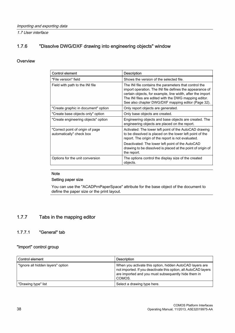
1.7.6 "Dissolve DWG/DXF drawing into engineering objects" window
Overview
Control element Description"File version" field Shows the version of the selected file.Field with path to the INI file The INI file contains the parameters that control the
import operation. The INI file defines the appearance of certain objects, for example, line width, after the import The INI files are edited with the DWG mapping editor. See also chapter DWG/DXF mapping editor (Page 32).
"Create graphic in document" option Only report objects are generated."Create base objects only" option Only base objects are created."Create engineering objects" option Engineering objects and base objects are created. The
engineering objects are placed on the report."Correct point of origin of page automatically" check box
Activated: The lower left point of the AutoCAD drawing to be dissolved is placed on the lower left point of the report. The origin of the report is not evaluated.Deactivated: The lower left point of the AutoCAD drawing to be dissolved is placed at the point of origin of the report.
Options for the unit conversion The options control the display size of the created objects.
NoteSetting paper size
You can use the "ACADPrnPaperSpace" attribute for the base object of the document to define the paper size or the print layout.
1.7.7 Tabs in the mapping editor
1.7.7.1 "General" tab
"Import" control group
Control element Description"Ignore all hidden layers" option When you activate this option, hidden AutoCAD layers are
not imported. If you deactivate this option, all AutoCAD layers are imported and you must subsequently hide them in COMOS.
"Drawing type" list Select a drawing type here.
Importing and exporting data1.7 User interface
COMOS Platform Interfaces38 Operating Manual, 11/2013, A5E32019975-AA

"Export" control group
Control element Description"DWG/DXF version" list Select the AutoCAD version used here."Create polylines instead of lines/arcs" option AutoCAD knows true circles and circles composed from line
segments. The true circles can only be fully controlled externally as of AutoCAD 2000.● In the "DWG/DXF version" list, "14" is selected and the
option is deactivated: Circles are exported as true circles. The circle attributes are not exported and the circle is drawn in AutoCAD with default parameters.
● In the "DWG/DXF version" list, "14" is selected and the option is activated: Circles are exported as polylines composed of numerous lines. The circle attributes, such as color and line width, are exported.
● In the "DWG/DXF version" list, "2000" or a higher version is selected and the option is deactivated:Circles are exported as true circles. The circle attributes are also exported.
● In the "DWG/DXF version" list, "2000" or a higher version is selected and the option is activated:Circles are exported as polylines composed of numerous lines. The circle attributes are also exported.
"'ByLayer' setting for color/line type" option ● Deactivated: The COMOS settings for colors and line types are exported.
● Activated: The AutoCAD settings are applied."Export symbol texts as attributes" option ● Deactivated: Symbol texts are exported as MTexts.
Dissolve the symbol in AutoCAD before changing it.● Activated: Symbol texts are exported as block attributes.
You can change a symbol in AutoCAD without dissolving it.
"Export pipe as polyline" option ● Deactivated: Pipes are exported as blocks.● Activated: Pipes are exported as polylines. All pipe texts
and additional symbols are exported as a common block."Ignore layers of symbol components" option ● Deactivated: The layer of the complete symbol and the
layers of the symbol parts are exported. To hide a symbol in AutoCAD, hide the layers of the complete symbol and all symbol parts.
● Activated: Only the layer of the complete symbol is exported. You can hide and show the symbol faster in AutoCAD.
"Use Text instead of MText" option ● Deactivated: MTexts are generated with an export.● Activated: Texts are generated with an export.
"Dissolve report template" option ● Deactivated: Document name and drawing header are exported as a separate block.
● Activated: Document name and drawing header are exported to the topmost layer of the AutoCAD file.
Importing and exporting data1.7 User interface
COMOS Platform InterfacesOperating Manual, 11/2013, A5E32019975-AA 39

Control element Description"One block definition per base object" option ● Deactivated: A separate block header is exported for each
symbol placed on the report. ● Activated:
– Only one block header is exported for symbols with the same base object.
– The "Export symbol texts as attributes" option is activated automatically. This prevents the symbol texts of the individual symbols from being lost.
– The information about whether and how a symbol was locally overwritten is lost.To maintain local symbols, activate the "Use template file (Export.dwg)" option.
"Use template file (Export.dwg)" option You can overwrite the export settings from the DWG/DXF mapping editor subsequently in the template file.● Deactivated: The template file is not evaluated.● Activated: The template file is evaluated.
"Export document frame" option ● Deactivated: The document frame is not exported.● Activated: The document frame is exported.
"Export document title" option ● Deactivated: The drawing header is not exported.● Activated: The document header is exported.
"Pipe flag class" field Enter the identifier of the pipe class in the symbol. All symbol parts that belong to the pipe flag are exported in a block.
"Reference class" field Enter the identifier of the pipe reference in the symbol. All symbol parts that belong to the reference are exported in a block.
1.7.7.2 "Line types" tab
OverviewThis tab is not evaluated for the export.
The following allocation is always applied:
DWG/DXF line type COMOS line typeCONTINUOUS 1ACAD_ISO02W100 2ACAD_ISO03W100 2ACAD_ISO04W100 4ACAD_ISO05W100 5ACAD_ISO06W100 1ACAD_ISO07W100 9ACAD_ISO08W100 2ACAD_ISO10W100 3
Importing and exporting data1.7 User interface
COMOS Platform Interfaces40 Operating Manual, 11/2013, A5E32019975-AA

1.7.7.3 "Colors" tab
OverviewThis tab is evaluated for the export.
You have the following options:
● "Set COMOS color automatically" option activated: The color is assigned automatically. A matching AutoCAD color is found based on the RGB values.
● "Set COMOS color automatically" option deactivated: You make the color assignment yourself:
– Select a color in the "DWG/DXF color" column. The DWG/DXF color index is displayed automatically.
– Select a color in the "COMOS color" column. The RGB values are displayed automatically.
– Select the width of lines with this color in the "COMOS line width" column.
1.7.7.4 "Layer" tab
OverviewYou assign the layers in this tab.
If a COMOS layer is not yet entered in the "dxf.ini" in the COMOS drawing, insert the COMOS layer here. The assigned AutoCAD layer then has the same name as the COMOS layer. If the COMOS layer has already been entered, the AutoCAD layer is assigned for the object.
1.7.7.5 "Combinations" tab
OverviewYou define how special objects are converted in this tab.
You describe all convertible properties of an object. If objects with these properties are found during the import or export, they are converted as defined.
Importing and exporting data1.7 User interface
COMOS Platform InterfacesOperating Manual, 11/2013, A5E32019975-AA 41


XML connectors 22.1 Basic principles
2.1.1 Introduction
Definition of XML connectorAn XML connector is an object of the document type used to build interfaces. The XML connector consists of a template, in which the configuration is stored, and the document. An XML connector additionally requires queries to create the mapping between XML data and COMOS data.
Following specialties are provided by an XML connector:
● Checking data in and out
● Mapping via XPath
● Support for queries in order to find objects
● Scripting to enhance the functions
● Triggering processes via the Enterprise server
● Interface between COMOS and external applications
● Delta management
● Versioning
FunctionXML connectors import and export data that are structured in accordance with a valid XML format. The XML format does not necessarily need to correspond to COMOS’s own XML format.
The assignment between COMOS data and XML data basically can be bidirectional. An XML connector in COMOS can be used to both read and to write XML data.
COMOS Platform InterfacesOperating Manual, 11/2013, A5E32019975-AA 43
2.1.2 RequirementThe following requirements must be met when working with XML connectors:
● You have experience with queries.You can find additional information on this topic in the "COMOS Platform Operation" manual, keyword "Working with queries".
● Before you create and implement XML connectors, define the design structures and objects to be imported or exported.
● You need to be familiar with the target XML structure described by the data.This simplifies the configuration of the XML connectors.
2.1.3 Basic concept of data mapping
OverviewBasically, there are four different option available for mapping data:
● Drag&drop assigning
● Conversion of values via standard tables
● Formation of object hierarchies through nested queries
● Formation of object hierarchies via reference columns
2.1.4 Maintaining old connectors prior to version 9.0
OverviewAs of version 9.0, XML connectors are no longer processed with VB script.
All old functions continue to be supported. The old connectors are downwards compatible.
Progress barIf you use connectors with VB script, a second window that shows the progress opens after importing or exporting has been started.
2.1.5 Connector document
OverviewCOMOS XML connectors are documents of the type "XML connector document". You usually create documents in the "Documents" Navigator tab or link the document to the tab. See also chapter XML connector documents (Page 47).
XML connectors2.1 Basic principles
COMOS Platform Interfaces44 Operating Manual, 11/2013, A5E32019975-AA

Document groupsYou can group documents into document groups to make the layout of the "Documents" tab in the Navigator clearer.
Connector documents that were triggered via the Enterprise server should be saved in an own document group. Create this document group directly below the project node. Name the document group "@MXC".
Connector documents that are not triggered by the Enterprise server can be saved at any location in COMOS where documents are allowed.
Reference objectYou assign a template and a reference object to the object in the "XML document" tab in the properties of the connector document. The reference object is the start object of the XML connector document and contains the objects that are exported. The objects to be imported are created below the reference object.
The reference object is stored in the connector document, not the connector template. It can be changed when the connector document is triggered.
ConfigurationConfigurations of the connector document are stored in the connector template. When you open the connector document for the configuration, the available configurations are loaded from the connector template. See also chapter Connector template (Page 45).
2.1.6 Connector template
OverviewThe template for XML connector documents must be an "XML connector template" type. Every XML connector document must be linked to a connector template. A connector template can be linked to several connector documents.
Create a document group for connector templates.
Assign the "@30 > M02 > A80 > A10 document object for XML connector" base object or an object below it to the connector template.
2.1.7 Basic principle of XML connectors
Structure of a typical XML fileXML files contain a tree-like structure. The individual levels of the hierarchy are collections of similar elements. You can freely choose the names of these collections. The name "Loops" is used in the following example.
XML connectors2.1 Basic principles
COMOS Platform InterfacesOperating Manual, 11/2013, A5E32019975-AA 45

<?xml version="1.0" encoding="UTF-8" ?>- <XML_Export>- <loops Test=""> <loop no="F4455"/> <loop no="L4444"/> <additional_loop_data> -<loop_identification> <subproject_no>W1</subproject_no> <unit_main_no>H1</unit_main_no> <unit_sub_no>T1</unit_sub_no> </loop_identification> </loops></XML_Export>In the "<loops Test="">" level of the collection, there are two "loop" nodes, which represent the elements of the collection.
2.1.8 "Envelope" field
OverviewThe "Envelope" field can be found in the "Attributes > XML" tab in the properties of the XML connector document. To edit the field, click on the "..." button.
You can use the "Envelope" field to enter fixed strings to enclose the XML content and declare the XML format. The XML version and the code used are displayed here.
The following rules apply for the "Envelope" field:
● The root node of the XML file must match the node that you have specified in the "XML start node" field of the configuration tool.
● If you want to use XML name spaces, you need to enter them in the "Envelope" field.
Example<?xml version="1.0" encoding="UTF-8" ?><CAETest xmlns:cis="http://www.siemens.com"><Content/></CAETest>You then insert the data generated in the XML connector at the location of the <"Content/"> placeholder.
XML connectors2.1 Basic principles
COMOS Platform Interfaces46 Operating Manual, 11/2013, A5E32019975-AA

2.1.9 Supported codes MotionX supports codes up to UFT-16. Pure Unicode, such as UTF-32, is not supported.
ExampleTo ensure correct processing of the XML file, the following definition cannot be included:
<?xml version="1.0" encoding="UTF-32"?>
2.2 XML connector documents
2.2.1 Creating an XML connector document
Procedure1. Open the engineering project
2. Select the "Units", "Locations" or "Documents" tab in the Navigator.
3. Create a new document of the "XML connector document" type.
4. Open the properties of the document.
5. Select the "XML document" tab.
6. Click the "..." button next to the "Template" field.The attributes are taken from the template and the queries below are evaluated.
7. Assign a template to the document.
8. If required, change the default setting in the "Reference object" field.This field sets the default setting for the "Query start object" field.
A common XML connector document The same XML connector is used for import and export, i.e., the same XML connector document with the same XML connector template.
2.2.2 Opening the configuration tool
Procedure1. Open the context menu of the XML connector document.
2. Select the "XML > Configure XML connector" command.
XML connectors2.2 XML connector documents
COMOS Platform InterfacesOperating Manual, 11/2013, A5E32019975-AA 47

2.2.3 Configuration of queries
OverviewTo select a query type for the XML connector document, click in the "Base object" field in the "Edit query container" window. See also chapter Connecting a query with XML connector (Page 58).
The following query types are available:
● "Query: Base objects"
● "Query: Connectors"
● "Query: Object engineering" (engineering objects)
● "Query: Documents".
● "Query pointer"
● "Query: Specifications" (attributes)
Which query type you select depends on the object you process.
You save predefined queries on the "Base objects" tab in the "@99 > A30 > M00 > A60 XML connector data" node. The queries you created can then be selected in the "Base object" field.
RuleTest the query before linking it to the XML structure.
Naming queriesThe name of queries for connector documents must begin with a letter. Names of queries are used in the script as name of subfunctions. Subfunctions must begin with a letter due to a Microsoft convention. A script error occurs if a subfunction has a number as its first character.
Special tasks for importingYou only have to configure the queries for imports to ensure they are also capable of creating new row objects.
2.2.4 Reusing queries
OverviewQuery pointers reduce data redundancy by excluding duplicates.
XML connectors2.2 XML connector documents
COMOS Platform Interfaces48 Operating Manual, 11/2013, A5E32019975-AA

Base objectThe base object for query pointers is located under "@99 > A30 > M00 > A60 > A10 Query pointer".
FunctionWithin XML connectors, you define an object that refers to a query inside or outside the connector. The query pointer is the copy of the target query and therefore has the same functionality. Lower level queries are also considered. If a query pointer is found during the processing of an XML connector document, the target query is used to import or export COMOS objects. See also chapter Assigning a query using properties (Page 49).
2.2.5 Assigning a query using properties
Procedure1. Open the properties of the "@99 > A30 > M00 > A60 > A10 Query pointer" node.
2. Select the "Attributes > Query pointer" tab.
3. Use the "Set pointer..." button to select the desired query.
2.2.6 Drag&drop assignment
Linking via drag&dropCOMOS uses tables to link COMOS data to XML data. You can link XML data to COMOS objects in the "Mapping" tab of the configuration tool. To link the XML data to a query, assign the corresponding XML node to a column of the query via drag&drop.
"COMOS" tabIn the case of linked data, the query refers to the object collection you create in the "COMOS" tab. You select the object collection type by dragging the desired object from the Navigator into the "Class(es)" field and the "Base object(s)" field of the query.
"Mapping" tabIn the "Mapping" tab, complete the query that is to be evaluated in the "XML" tab. The evaluated COMOS objects of the query are displayed in the "COMOS" tab. The evaluated XML nodes are displayed in the "XML" tab.
Therefore, there are two object collections, one for COMOS objects and one for XML nodes.
First, edit the "XML collection" field in the "Mapping" tab.
XML connectors2.2 XML connector documents
COMOS Platform InterfacesOperating Manual, 11/2013, A5E32019975-AA 49

The collection of XML nodes is created based on the node that you dragged from the XML file and dropped into the "XML collection" field in the "Mapping" tab. This automatically creates the XPath expression, which points to the desired node. The XPath expression in the "XML collection" field depends on the entry in the "XML start node" field. The XPath expression indicates the position of the nodes contained in the XML collection, depending on the entry in the "XML start node" field.
You can see the columns of the query used in the lower section of the "Mapping" tab. This is where you link the COMOS data with the XML data. The columns of the query are displayed as rows in the mapping table. When you drag&drop an XML node to a cell in the "XML mapping" column, you assign the XML node to the corresponding column of the query. The XML connector document then knows which XML value needs to be entered in the assigned column during runtime. The XPath expression generated in the "XML mapping" column depends on the entry in the "XML collection" field.
"XML" tabIf the XML table in the "XML" tab has been filled out correctly, the data is successfully linked.
2.2.7 Creating objects with different base objects via a query
RequirementThe "COMOS" tab must be open in the configuration tool.
There are two columns: one for creating the object and one for the base object.
Configuring the column for the base object1. Open the properties of the column which is to return the base object for creating new objects.
2. Click on the "Object by value" tab.
3. Select the "Base object search" entry from the "Calculation mode" list.
4. Drag-and-drop the desired base object into the "Start object" field.When you create a new object, this base object then serves as the start object for searching for base objects.
5. Click "OK".
Setting the base object properties1. Open the base object properties.
2. Drag&drop the base object you want to set the reference for into the "Base object" field in the "System" tab.
3. Activate the "Dereference" option.
4. Save your entries.
XML connectors2.2 XML connector documents
COMOS Platform Interfaces50 Operating Manual, 11/2013, A5E32019975-AA

ResultThe reference object serves as a library object for the new object that is to be created.
Setting the column for the engineering objectProceed as follows to make the settings for the second column:
1. Open the properties of the master column.
2. Select the "Object by value" tab.
3. Select the "Default definitions(For engineering objects only)" item from the "Calculation mode" list.
4. From the "Owner object" list, select the object under which new objects are to be saved.
5. Select the "Neighbor cell object" item from the "Base object" list.
6. Select the name of the column that you have defined from the list of the neighbor cells.
7. Save the settings.
8. Close the column properties.
Creating an object1. Enter the name of the base object that you want to use to create a new object in an empty
cell of the column you have defined for the start object of the base object search.
2. The cell returns the found base object as the value.
3. The object is created below the specified start object of the query. If no base object is found below the start object for the search, a new base object is created.
2.2.8 References
References in COMOSIn COMOS, references are used in addition to the object hierarchy to create logical links between items of information. You can find additional information on this topic in the "Class Documentation COMOS_dll" manual.
ReferenceA reference is a function or property that contains connection information for an individual object and can be read as well as written. You can find additional information on this topic in the "Class Documentation COMOS_dll" manual, keyword "Reference".
For example, you can save the information about a component belonging to a specific location. To do this, you do not need to place the component below the location. You can the save reference to the location at the component: "Device.Location". "Device" is the component and "Location" is the reference to the location.
XML connectors2.2 XML connector documents
COMOS Platform InterfacesOperating Manual, 11/2013, A5E32019975-AA 51

Another example is the link between two connectors. There is a collection of connectors below a component. These connectors can be linked to the connectors of another component, which would then have the following reference: "Connector.ConnectedWith".
References in XML XML manages references using the following pointers:
● ID: Information
● IDREF: Reference to this information
Therefore, there can be multiple IDREFs for a single ID.
See also chapter Configuring references in the XML connector (Page 52).
2.2.9 Configuring references in the XML connector
Procedure1. Since the target information has to have an ID, create an "ID" column.
2. Select the "New > General" command in the context menu of the "Name" column.
3. Enter the desired name in the "Name" and "Description" fields, for example "ID Number".COMOS automatically generates the IDs in this column.
4. Since IDREF searches for the ID, the object with the ID must be known. Be sure you find the right object with the ID in the definition of the IDREF. Select one of the following options:
– The objects in which the IDREFs is defined are a different object group than the objects with the ID. You can create two queries for the "Device.Location" example: One that searches the locations and generates the ID and a second query that searches for the component and generates the IDREF.You can use the REFID collection method. Background: COMOS does not export any empty queries to XML. If you create a query whose sole task is providing the ID, this query will only be exported if the IDs are required. If COMOS encounters an ID column, COMOS remembers the SystemUID and that an ID must be resolved to an object here. When at least one IDREF requesting an ID is not found and the query otherwise does not export defined XML elements or XML attributes, this object will not appear in the XML file.
– The objects all belong to a group and are efficiently searched with a query. For the "Connector.ConnectedWith" example, you can search all connectors in a single query and also generate both the ID and the IDREF in this query. Then right-click in the header of the "Name" column and select the context menu command "New > Connected > Connector".
5. Switch to the "Mapping" tab and specify the following XML mapping: See also chapter Examples of XML mapping (Page 53).
XML connectors2.2 XML connector documents
COMOS Platform Interfaces52 Operating Manual, 11/2013, A5E32019975-AA

2.2.10 Examples of XML mapping
Examples
Assignment Description"Objekt > Name": @Name This column is already present in the query. Recommendation: Always
export the name of the objects as well, in this case the name of the connection objects.
"ID-Nummer > ID-Nummer": @ID You have created this column in the query. The ID is generated in this column in the next step. The column can also have another name than "ID".
"Object_ConnectedWith > Conn. connector": @IDREF_ConnectedWith
This column is to put out the IDREF in the next step. To do this, you first have to find the object with the target ID using the predefined column "New > Connected > Connector". To verify this, open the properties of the column in the "COMOS" tab. The properties show the "ConnectedWith" navigation step in the "Object evaluation" tab. This is a COMOS reference that is calculated from the "Object > Name" column. The mapping is made with the definition of IDREF. Here, you have to ensure that the object with the ID is found.Similar to the "ID Number" column, you can enter the XML mapping "@IDREF" here. However, the legibility of the XML file increases when you specify the kind of reference it pertains to. Recommendation: An XML mapping such as "@IDREF_ConnectedWith".
Corresponding XML type Make the following settings based on the example:
XML connectors2.2 XML connector documents
COMOS Platform InterfacesOperating Manual, 11/2013, A5E32019975-AA 53

● "ID-Nummer > ID-Nummer": @IDClick on the desired cell in the "Corresponding XML type" column to set the focus to this cell. Click on the cell again to activate the list and select the "ID" entry. Only then is the ID generated and the ID is assigned a SystemUID internally.
● "Object_ConnectedWith > Conn. connector": @IDREF_ConnectedWithClick on the desired cell in the "Corresponding XML type" column to set the focus to this cell. Click on the cell again to activate the list and select the "IDREF" entry. Only then is the IDREF generated.
2.2.11 COMOS Collection (REFID)You can only set one start object for an XML connector.
After that, the queries that are located below the start object are executed for each row in turn.
ExampleYou want to find the locations that are used for a set of engineering objects. To do this, insert a column in the query that outputs the reference to the location for each engineering object.
Previous work methodYou cannot create a clean XML structure with already described work methods:
● There is always exactly one initial start object for the export, for example, a unit in the "Units" tab in the Navigator.
● You can search for the components below the unit using a query, for example. You can output all attributes, and thus also the reference to the location for these components.
● However, in order to establish a correct relation of Component (IDREF) to Location (ID), you need the location objects. An XML connector is executed by searching for objects staring from a start object. Each of the found objects can be forwarded as a start object to a query that is located deeper in the hierarchy. Since no locations are found below the start object, you cannot forward a location for a start object to a deeper query. You will not find the location objects.
Collection REFIDIn this case, you should use the REFID collection. This method discards the "Query passes start object for deeper query" method. With regard to the configuration tool, this means that the "Query start object" field is no longer of any significance.
Instead, a collection is formed that contains all objects that were previously already used. See also chapter Defining the COMOS collection (Page 55).
XML connectors2.2 XML connector documents
COMOS Platform Interfaces54 Operating Manual, 11/2013, A5E32019975-AA

2.2.12 Defining the COMOS collectionThis example describes engineering objects, the references of which are written to a location in an XML file.
Procedure1. Create a query in which the engineering objects are collected.
2. Click on the column and select the "New > Location" command from the context menu.A new column, "Location", is created.
3. Mark the new row, "Location", in the "Mapping" tab.
4. For the "Location" row, select the "IDREF" entry from the "Corresponding XML type" column.
5. Create a query that collects locations below the existing query.A column with an ID is created in this query as a counterpart to the above IDREF.
6. Click on the column and select the "New > General" command from the context menu.A new column, "ID", is created.
7. Mark the new row, "ID", in the "Mapping" tab.
8. For the "ID" row, select "ID" from the list in the "Corresponding XML type" column.
9. In the query in the "Mapping" tab, select "REFID objects" from the "COMOS collection type" list.
ResultYou get an XML structure. However, the REFID collection is formed on demand during the course of the export. Previously used objects in this collection are not deleted again.
This means an ever increasing number of XML elements are created in the XML files during the export operation.
2.2.13 Mapping table for values
Data conversion during runtimeYou have the option of converting XML data before saving it in COMOS. You can also convert COMOS data before saving it in an XML file. You use standard tables in order to transform data. You define a standard table where a column with COMOS values and a column with XML values are available. If an external value is found in the column of XML values during runtime, the corresponding value from the column of COMOS values is written to the query.
XML connectors2.2 XML connector documents
COMOS Platform InterfacesOperating Manual, 11/2013, A5E32019975-AA 55

Examples● You want to convert text into another key text. In COMOS, "mm" is used for the millimeters
unit, but the string "Millim." needs to be in the XML file.
● Import or export values are to be assigned to another value on the basis of a fixed key. Multiple import values form a COMOS value or vice versa.
Such a simplified mapping excludes a bidirectional mapping. In such a case you either export nor import.
See also chapter Transforming data during runtime (Page 56).
2.2.14 Transforming data during runtime
Procedure
1. Select the "Administrator > Base data > Standard tables" command in the menu bar.
2. Drag&drop the required standard table to the "Mapping table" column.You can use standard tables from the engineering project, the base project or the system project. COMOS only stores the name of the standard table and not the project from which the standard table derives. COMOS first searches for the standard table in the engineering project, then in the base project, and finally in the system project.If you select a standard table from the base project and there is a standard table with the same name but different content in the engineering project, the standard table from the engineering project is found.
You can find additional information on this topic in the manual "COMOS Platform Operation".
"Column with COMOS values" / "Column with external values"These two columns relate to the standard table specified in the "Mapping table" column.
A column of the standard table is specified in both columns. One column has to contain the COMOS values, the other the values to be imported or exported.
The two columns must contain different data.
If you enter this key text, the "Name", "Description", and "Value 1" through "Value 10" columns of the standard table are used.
2.2.15 "COMOS info" columnAutomatically generated static information is entered in the "COMOS info" column. This data is generated by this column of the query.
Each row in the tab represents a column of the query.
The information can be imprecise, for instance if you are working with a script.
XML connectors2.2 XML connector documents
COMOS Platform Interfaces56 Operating Manual, 11/2013, A5E32019975-AA

2.2.16 Check column
Enterprise serverThe Check column writes information about the values of the row to the Enterprise server:
Check columns are always executed at the end of the calculation of a row. When the check column function is executed, all other cell values of this row are available and can be queried.
If the Enterprise server started an XML connector, all values of the check column are written to the MXR file (response file).
2.2.17 XML fragments (XFRAG)
DefinitionXML fragments are strings that are not evaluated nor changed and passed to an XML file. Make certain that these strings comply with the applicable XML syntax and contain meaningful content. See also chapter Creating an XML fragment (Page 58).
The fragment name ● Export
If the attribute to be exported has a valid XML string, the entire <Fragment> node is generated. If the XML string does not have a valid XML syntax, the fragment name is generated as an XML element <Fragment>.
● ImportThis information is required for the import in order to find the fragment in the XML file. With this entry, the entire <Fragment> node is written to the attribute as an XML string in COMOS during the import. There may be several fragments within the XML file. The fragment name must be oriented towards the XPath syntax.
ExampleXFrag("ABC/XY")
XFrag("MN")
RuleIf you perform a reimport, make sure the in the memo field entered string has the same root name as the fragment name.
XML connectors2.2 XML connector documents
COMOS Platform InterfacesOperating Manual, 11/2013, A5E32019975-AA 57

Example● String in the memo field:
<Fragment X1="234" X2="CX"> <SubFragment>Greetings!</SubFragment></Fragment>
● XML assignment:XFRAG(""Fragment"")
2.2.18 Creating an XML fragment
Procedure1. Prepare a "Memo field" type attribute at the objects in the base data.
2. Enter the string in the memo field of the engineering data.
3. In the "COMOS" tab of the configuration tool, create a reference column using the context menu. See also chapter Opening the configuration tool (Page 47).
4. To create a new column, select the desired column "New > General" from the context menu.
5. Fill out the name and description of the new column.
6. Select the "Object evaluation" tab of the new column.
7. Select "SpecificationByNestedName" from the "Navigation step" list.
8. Enter "<Name of tab.Name of attribute>" for the parameter.
9. Select "GetDisplayXValue" in the "Display" field of the "Value calculation" tab and enter "0" as the index in the "Parameter(s)" field.
10.Save the properties of the column.
11.Select the "Mapping" tab in the configuration tool and enter the newly created row "XFRAG ("Fragment name")" in the "XML mapping" column.
2.2.19 Connecting a query with XML connector
ProcedureOnce you have created the connector document, you can also create the query using the configuration tool of the XML connector document.
1. Select the "XML > Configure XML connector" command in the context menu of the connector document.See also chapter Opening the configuration tool (Page 47).
2. Click on the "..." button next to the "Query" list.
3. In the "Edit queries" window, right-click on the XML connector template and select the "New > Query" command from the context menu.
XML connectors2.2 XML connector documents
COMOS Platform Interfaces58 Operating Manual, 11/2013, A5E32019975-AA

4. The "Edit query container" window opens:
5. Enter the desired name in the "Name" field.
6. Select a query type in the "Base object" field.See also chapter Configuration of queries (Page 48).
7. Click "OK".The "Edit queries" window opens: The query is now displayed.
"Base objects" Navigator tab● If you have already worked with XML connectors in the database, you find the basic types
at the following location:
– "@99 > A30 > M00 > A60 XML connector data"
These queries have no default settings or permission restrictions. The node is created automatically by COMOS when you create a new query using the configuration tool. Click "OK" to apply the settings. A node is created.
● If this node does not yet exist, you will find the queries at the following location:
– "@99 > A20 > M00 > A40 Menu entry 'Extra'"
RecommendationCheck if the query can be fully edited.
2.2.20 Column propertiesWhen you open a query, you see the table with the column headers. You can also see this table via the configuration tool in the "COMOS" tab. See also chapter Opening the configuration tool (Page 47).
Tabs in the properties of the columns
Tab Description"General" You make general settings for the column properties here."Object evaluation" An object is calculated here. The information gathered from this
object is displayed in the object browser."Value calculation" Value calculation uses the object of the object evaluation for further
information processing. The value calculation cannot supply a result unless a correct definition is provided in the "Object evaluation" tab.
"Object by value" You define rules for creating new objects.This requires you to select the "Options" command in the context menu of the column header and activate the "Permit new row" option in the "Editing type" control group in the "General" tab.
"Extra" You make additional settings for the column properties here."Languages" This tab shows the name of the column in various languages.
XML connectors2.2 XML connector documents
COMOS Platform InterfacesOperating Manual, 11/2013, A5E32019975-AA 59

2.2.21 Direct help in the configuration tool
HyperlinksYou will find a help section consisting of hyperlinks in the lower right of the application area.
When you click on the text in the help area, a window opens in which you perform the suggested work step.
2.3 Configuring the export of XML data
2.3.1 Basic principles
Configuration of the connector documentsYou can configure the connector document in the "Mapping" tab of the configuration tool. See also chapter Opening the configuration tool (Page 47).
Execute the following tasks:
1. Separate the COMOS data and XML data into groups of similar data by assigning COMOS objects to the corresponding XML nodes.
2. Create tables that can describe both XML and COMOS data. Use one table for each data group. You can represent hierarchical structures using nested tables.
3. Select one or more data fields through which the table entries can be uniquely identified. These fields serve as key columns.Not all XML structures can be displayed in tabular form. In this case, use a VB script or C# code.
COMOS data is collected using the standard COMOS query methods; XML data is collected via XPath. You can use VB script or C# code to collect data from complex COMOS or XML structures. See also chapter Extending an XML connector through a C# assembly (Page 69).
XML connectors2.3 Configuring the export of XML data
COMOS Platform Interfaces60 Operating Manual, 11/2013, A5E32019975-AA

2.3.2 Assignments in the "XML mapping" columnThe following naming conventions are used for XML mapping:
Structure description "/" and attribute description "@"Individual descriptions as well as mixed descriptions are allowed. The XML mapping "@Label" uses and generates an XML attribute with a corresponding name. The XML mapping "/Unit1/Position1/" creates a corresponding XML structure, i.e. a hierarchical sequence of nodes.
"/Unit1/@Label" is also allowed.
Default: Forward slash "/".
If the "/" as well as the "@" sign are missing, the "/" is used by default to create a structure.
Empty XML elementsElements that have no additional attributes or elements are empty.
Technically speaking, you can create empty XML elements.
Recommendation: Create only XML structures that have at least one attribute or one value in the last level, for example "<Position> P001 </Position>".
ResultEach column of the "COMOS" tab is displayed as a separate line in the "Mapping" tab.
2.3.3 Comparing XML data and COMOS data
ExampleYou will already be familiar with the method for comparing the exported XML file with the "Mapping" tab:
XML connectors2.3 Configuring the export of XML data
COMOS Platform InterfacesOperating Manual, 11/2013, A5E32019975-AA 61

The objects collected in this query were exported as "Position" XML elements. The XML attributes "Tag" and "Description" were created in this XML element.
The content of the "COMOS" tab should match that of the generated XML elements.
2.3.4 Nested queriesYou usually will be working with a data hierarchy. In such cases, a search is performed for a set of objects, and under each object found, the search continues for additional objects.
You can perform such tasks with the help of nested queries.
SortingIf you create the queries below the XML connector, you have to keep two things in mind when assigning names:
● The queries are processed in the order in which they appear in the "Queries" list. The sequence of the queries is defined solely by their names. If you require a specific execution sequence, adapt the names accordingly.
● The names of the queries must begin with a letter. If the name of a query begins with a number, the name cannot be used as a function name in the script. This results in a script error.
Effects to the base dataAll entries in the "Edit query container" window have an effect on the connector template. Deleting queries affects all XML connectors that access the connector template.
Hierarchically nested queriesIf there are different collections on a level of the XML file, create a query for each of collection. Each query is then dedicated to a single collection.
Example
Both queries are dedicated to the same level of the XML file. However, each of the queries handles a different collection of information on this level. For this, the queries are called as often as required.
The queries "Attribute HSD" and "Attribute SYS" are called for each object of the "Q11 functions" query.
XML connectors2.3 Configuring the export of XML data
COMOS Platform Interfaces62 Operating Manual, 11/2013, A5E32019975-AA

Changing between the queriesAll queries saved below the template are available in the "Queries" list.
When you select a query, the "COMOS" tab is updated. The columns and settings of the selected query are thus displayed.
Query start object and reference objects with multiple queries● For queries located directly below the XML template, the "Query start object" field is initially
preassigned by the "Reference object" field.
● If you select another query in the list within the XML connector, the current selection is evaluated in the "COMOS" tab and is set as the start object.The REFID collection is an exception to this rule.
● You can use drag-and-drop to reset the start object of the query.This object is not saved. COMOS discards this manual setting as soon as you select another query.
● For queries located deeper in the hierarchy and not directly below the XML template, you can reset the start object The most recent setting is stored as long as the window is open.
You can set only one start point in an XML connector. This one starting point is set with the help of the "Reference object" in the "MotionX" window and applies to all queries directly below the XML template.
The entry in the "Reference object" field in the "MotionX" window is saved in the properties of the XML connector, in the "Reference object" field. Both fields contain the same information for XML documents. Since for technical reasons there can only be one reference object in COMOS, there is only one initial reference object for XML documents.
All other work steps are produced automatically and cannot be set manually.
This has consequences if the data to be exported is not located below a common node, but instead, for example, is distributed over the various tabs of the Navigator. In this case, you will need to use a VB script to collect the objects.
If the objects are associated via references, you can apply the REFID collection method.
Edit newly created queries You can also edit the queries directly in the "COMOS" tab.
Right-click in the column header and select an option from the context menu. For example, you can create a new column.
Ensure that you open the context menu from the correct column. The newly created columns relate to the column from which you open the context menu.
You can also check at a later point in time which reference column is set. To do so, open the properties of the newly created column. The reference column is shown in the "Reference" field of the "General" tab. However, this only applies if the query has been stored there.
XML connectors2.3 Configuring the export of XML data
COMOS Platform InterfacesOperating Manual, 11/2013, A5E32019975-AA 63
Effect in the base dataEach action described here changes the query in the base data. This applies also when you are processing the XML connector in an engineering project.
2.4 Configuring the import of XML data
2.4.1 Key columnsTake into consideration when assigning the COMOS data and the XML data that the order of data may change. The position of an item of information on a level cannot be used as the basis for mapping.
The import cannot be executed without key columns. Key columns link the rows of the COMOS table to the corresponding rows of the XML table.
There can be multiple key columns.
ReimportA configured XML connector is always based on a fixed XML structure. The data can be reimported through the XML connector as long as this XML structure remains unchanged.
If you do not define key columns, the data cannot be reimported.
In this case, you can call the import function, but the data will not be entered into the COMOS objects because these objects cannot be found.
Specifying key columnsEach query can have multiple key columns. The overall purpose of the key columns is to uniquely identify an object within a query in the XML connector.
ExampleThe sum of the name of the object, the unit, and the position are always unique in COMOS. If you create three columns in the query and fill them with name, unit, and position, respectively, and then define all three columns as key columns, you can then assign any object.
Key columns are required for the import. The COMOS objects to be changed are identified via key columns, or new COMOS objects are created or deleted.
The key columns are not relevant for the export.
XML connectors2.4 Configuring the import of XML data
COMOS Platform Interfaces64 Operating Manual, 11/2013, A5E32019975-AA

2.4.2 Master column
GeneralThe master column shows the query which cell contains the object that is to be searched for or created in the OrgCollection. The master column is a general function of queries.
There is only one master column.
2.4.3 Expressions supported for the import
OverviewThe following expressions are supported for the import but not for the export:
● Expressions with "OR", "AND"Example: /../Specifications/Specification [@Name="Temperature" OR @Name="Pressure"]A unique object must be addressed during an export.
● Expression for selecting an unknown node:/*, //, @*...etcExample: Valve/*
2.5 Using XML connectors
2.5.1 Exporting COMOS data
Procedure1. Open the context menu of the XML connector document.
2. Select the "XML > Export" command.
3. Make the required settings in the "MotionX" window. See also chapter "MotionX" window for the export (Page 83).
4. Click "OK".
2.5.2 Importing COMOS dataCheck the mapping between XML and COMOS data before the import. See also chapter Mapping table for values (Page 55).
XML connectors2.5 Using XML connectors
COMOS Platform InterfacesOperating Manual, 11/2013, A5E32019975-AA 65

Procedure1. Open the context menu of the XML connector document.
2. Select the "XML > Import" command.
3. Make the required settings in the "MotionX" window. See also chapter "MotionX" window for the import (Page 83).
4. Click "OK".
2.5.3 Progress bar
Double progress barThe progress of the import or export is displayed using a double progress bar. The upper bar shows the overall progress while the lower bar shows the progress of the current query. The name of the query is displayed below the progress bar.
2.5.4 XML adapter
FunctionA so-called job is started while the XML connector is running for each query. The job has a property that shows the query being used for the current import or export job.
You use the XML adapter to process COMOS and XML data both before and after the import or export.
JobOptionsIf JobOptions have already been created through the Enterprise server and forwarded to the XML adapter, for example, the settings only need to be read.
If you start the XML adapter from COMOS, the JobOptions must be created and adapted via the option of the interface.
Adapter typeA variety of components can implement the "IAdapterActions" interface. These components are assigned to the XML adapter via the "Adapter type" attribute in the "XML" tab. Here, in the list behind the "Adapter type" attribute in the "XML" tab, all the components listed in the properties of the XML connector are assigned a name.
XML connectors2.5 Using XML connectors
COMOS Platform Interfaces66 Operating Manual, 11/2013, A5E32019975-AA

Structure of the listThe following table describes the columns of the "A2GKGD4EPX" list:
Column Description"Name" This column displays the internal name."Description" This column shows the name of the component that can be selected
in the "Adapter type" list."Value 1" This column shows the internal name by which the adapter is
queried in order to load the special settings."Value 2" This column displays the name of the class to be loaded.
"KomponentenName.KlassenName" applies for all COM components. "Namespaces.ClassName" applies for all .NET components.
"Value 3" This column shows the "AssemblyName" of a .NET class. This value remains empty for COM components.
"Value 4" This column shows the path and the name of the XML file for internal processing.
2.5.5 Triggering connectors via a script The previous examples assumed that you have written a script in the configuration tool and then started it in the XML connector document using the context menu command " XML > Export" or "XML > Import".
You can also start the export or import via a script.
Example as of version 9.0● Creating the options
Set XMLImpExport = CreateObject("Comos.XMLConnector.Exec") Set Options = XMLImpExport.CreateJobOptions(<JobType>)
● Permitted values for <JobType>: 1 / 2 (1 for import, 2 for export)
● Setting an optionOptions.Item("<OptionName>").Value = <value>
● Available optionsOptions 1-4 are are only relevant for the import.
The following table describes the default values of the option:
Option Default value"DeleteObjects" false"CreateWorkingOverlay" true"DifferenceOnly" false"SaveMode" 0"VersionsAdministration" false"ShowFile" false
XML connectors2.5 Using XML connectors
COMOS Platform InterfacesOperating Manual, 11/2013, A5E32019975-AA 67

● Options as of version 9.0
Option Value Description"ProgressBar" Nothing The progress display as (.NET)
object."qeDialogType" 2 The type of the displayed dialog
window."Cancel" false Status / success of execution --
true = cancel
If you set the "ProgressBar" option manually to the value "Nothing", you must set "qeDialogType" to "0".
Set Options.Item("ProgressBar").Value = Nothing Options.Item("qeDialogType").Value = 0Values for "qeDialogType":
Value Description0 No window / no progress bar1 Full dialog with options, requires manual start by user2 Minimum dialog, only shows the progress bar
The above listed options must be changed as described for the server mode. This has already been received from the "MXExec.exe" file.
Starting the jobSet XMLAdapter = CreateObject("Comos.XMLAdapter.Adapter")Set <XMLCOnnector>.reportobject =<Reference object>result = XMLAdapter.LoadFromScript(<JobType>, <XMLConnector>, <Destination Filename>, Options)
Permitted values for <JobType>
Value Description1 Import2 Export
Return valueIf the "LoadFromScript" function was successfully executed, the return value of the function is "0".
XML connectors2.5 Using XML connectors
COMOS Platform Interfaces68 Operating Manual, 11/2013, A5E32019975-AA

2.6 Extending an XML connector through a C# assembly
2.6.1 Connector expansion for C# assemblies
RecommendationUse previously compiled DLLs and embed these in COMOS.
.NET development environmentTo use a previously compiled DLL, you need a .NET development environment that supports .NET Framework 3.5, such as Visual Studio 2005.
You can also use an editor to write source code directly in COMOS. You compile this source code during the configuration of the XML connector for an assembly.
COMOS does not provide any special functions for .NET development.
Debugging If you use Visual Studio, debug from the development environment. To do this, configure the project properties and declare Comos.exe under "Start external program" in the "Debugging" tab.
2.6.2 Creating a new C# assembly
Procedure1. Select the "Assembly" tab in the configuration tool. See also chapter Opening the
configuration tool (Page 47).
2. Select the "Write code" option.
3. Specify the desire C# source code in the editor.
4. Save the setting.
XML connectors2.6 Extending an XML connector through a C# assembly
COMOS Platform InterfacesOperating Manual, 11/2013, A5E32019975-AA 69

2.6.3 Loading existing assemblies
ProcedureThere are two ways to specify an already compiled assembly:
1. Enter the path and file name of the DLL file in the "Assembly file" field.This file is searched to find the "ICodeProviderActions" interface and an instance of the class you specified in the "Class name" field is created. The instance of the class implements the interface.In addition to the file path, you can also specify the fully qualified class name. The class name is formed as follows: "Namespaces.ClassName". If you specify the class name, the search targets an instance of the specified class instead of a class.
2. If you do not state the file name you have to state the assembly name and the fully qualified class name. The DLL of the assembly must be located parallel to the Comos.exe or in a subfolder of the "Comos\Bin" folder. If the DLL is located in a subfolder, you need to edit "Comos.exe.config" file. Specify the subfolders in which to search for DLLs.
RuleYou must always specify the assembly name.
ExampleThe subfolder is named "CompiledAssemblies". Enter the following line in the "Comos.exe.config" file:
<assemblyBinding><probing privatePath="Interop;CompiledAssemblies"/></assemblyBinding>The file name of the DLL must correspond to the name of the assembly: "AssemblyName".dll.
2.6.4 Class documentation
OverviewThe following describes the most important interfaces and properties you need to work with .NET assemblies.
See also chapter:
● "ICodeProviderActions" interface (Page 71)
● "IAdapterActions" interface (Page 72)
● "IJobHelper" interface (Page 73)
● "IXMLExecJob" interface (Page 74)
XML connectors2.6 Extending an XML connector through a C# assembly
COMOS Platform Interfaces70 Operating Manual, 11/2013, A5E32019975-AA

● "Preprocessing/postprocessing" adapter (Page 74)
● "Custom" adapter type (Page 75)
2.6.5 "ICodeProviderActions" interface
OverviewAll methods that are to be called by the XML connector must be defined beforehand for a .NET assembly. To ensure this, there is an interface that you need to implement when creating a class. This is the only way to guarantee that all classes follow the same scheme.
Interface:
1. short Version { get; }Returns the version of the implemented interface (currently 1).
2. bool ImportCalled for an import.
3. bool ExportCalled for an export.
ParametersThe following table describes the parameters of the interface:
Parameter (data type) Value DescriptionqueryName (string) @@Master Master call; forwarded
<Name of query> Call from query; forwardedjobHelper (IJobHelper) The 'jobHelper' parameter returns an
object with which you can access different environment variables of a job. These variables were made available globally in the VB script in the past; in other words, you could access them directly. Example for these variables: 'CurrentJob' (VB-Script) and 'CreateNewJob()' (C#)
comosObj (IComosBaseObject) Corresponds to the identically-named parameter from VB script.
XMLNode (System.Xml.XmlNode) Corresponds to the identically-named parameter from VB script.
XMLNodeCompare (System.Xml.XmlNode)
For import only Corresponds to the identically-named parameter from VB script.
XML connectors2.6 Extending an XML connector through a C# assembly
COMOS Platform InterfacesOperating Manual, 11/2013, A5E32019975-AA 71

ExplanationsThere is a difference between "Master_..." and "…_ExportRow". The same method is called in both cases. If a master call is involved, the method is passed via the 'queryName' parameter of the "@@Master" value. If a call from a query is involved, the method is passed via the 'queryName' parameter of the <name of query> value. Evaluate the forwarded parameter.
Do not randomly select the return value from both methods, since it will be interpreted and influences the execution of the job. The return value tells you if your actions were performed when a method was called – return value: TRUE. Since an assembly is saved for the entire connector and not for each query, you need to be able to distinguish when actions are performed. This is not possible before the methods are called. You can use the 'queryName' parameter to determine if the actions should be performed.
ExampleWhen you call the 'Export' with 'queryName' = "@@Master" method and want to extend the execution, the return parameter must have the value TRUE.
If FALSE is the return value, COMOS executes its standard procedure.
2.6.6 "IAdapterActions" interface
Structure of the interfaceThe interface is structured as follows:public interface IAdapterActions{ short Version { get; } short PostAction(string jobType, IComosDDocument document, ref string FileName, IOptions jobOptions); short PreAction(string jobType, IComosDDocument document, ref string FileName, IOptions jobOptions);}
Parameters
Parameter DescriptionVersion Returns the current interface version.PreAction Starts the PreAction of the XML adapter and runs before the XML connector
is started internally.PostAction Starts the PostAction of the XML adapter and runs after the XML connector
is started internally.jobType Name of the job type:
● Import● Export
document The XML connector document that is to be used. The XML document is a COMOS object.
XML connectors2.6 Extending an XML connector through a C# assembly
COMOS Platform Interfaces72 Operating Manual, 11/2013, A5E32019975-AA

Parameter DescriptionFileName Name of the XML file that is to be used.
Note: This is a REF parameter. If the value is changed within the method, this change persists after the method is called and is, therefore, retained throughout the remainder of the XML connector process.
jobOptions Options for the XML connector. The options are defined (via the user interface, for example) before the connector starts.
2.6.7 "IJobHelper" interface
OverviewThe following table describes methods and properties.
Method/Property DescriptionIComosDDocument Document { get; } Returns the Document property of the current job.
Note: The document is the COMOS XML connector.ComosQueryInterface.IOptions Options { get; } Returns the external options of the current job.ComosQueryInterface.qeProgressState ProgressState { get; }
Returns the status of the progress bar.
IComosDProject Project { get; } Returns the current project.IJobHelper ThisGlobal { get; } Returns itself.IComosDWorkset Workset { get; } Returns the instance of the currently created workset.XMLExecJob Currentjob { get; set; } Returns the started job and sets a job and thus all parameters
depending on it (e.g., document, options).string ProgressText { get; set; } Returns and sets the text of the progress bar.string XMLFileName { get; set; } Returns and sets the name of the processed XML file.double GetProgressPercentage(int level) Returns the progress of the passed levels of the current
progress bar.Permitted parameter values:1, 2.
void SetProgressPercentage(int level, double value)
Sets the progress of the passed levels of the progress bar.Permitted parameter values: 1, 2 – level ; 0 to 100 – value
void CheckMessage(string msgText) Writes a text to the log file. Syntax:<check description="<<msgText>>" />
XMLExecJob CreateNewJob() Creates a copy of the current job.void OutputDebugString(string lpOutputString) Writes a text to the trace listener 'QueryX'. The associated
file is defined in the "Comos.exe.config" file.Note: The Trace.Listener property is .NET-Standard.
ComosQueryInterface.IProgressBar ProgressBar()
Returns the current progress bar as an object.
IComosBaseObject ReportObject() Returns the ReportObject property of the current document.
XML connectors2.6 Extending an XML connector through a C# assembly
COMOS Platform InterfacesOperating Manual, 11/2013, A5E32019975-AA 73

2.6.8 "IXMLExecJob" interface
MethodsThe following table describes the methods:
Method Descriptionvoid Export() Starts the export for the current queryvoid Import() Starts the import for the current query
PropertiesThe following table describes the properties:
Property (data type) DescriptionComosObjects (Object) Specifies the OrigCollection of the query. The property
returns one of the following three types:● ComosKDictionary● VBACollection● IComosDCollection
RootComosObject (IComosBaseObject) Start object of the queryQueryContainer (IComosBaseObject) Currently processed queryTopQuery (ITopQuery) Top query object of the queryRootXMLNode (System.Xml.XmlNode) Root start nodeRootXMLNodeCompare (System.Xml.XmlNode) Root start node for the "Difference Only" mode. Comparison
node from the predecessor file.XMLNodes (System.Xml.XmlNodeList) Lists all nodes to be processed; COMOS collection objectsXMLNodesCompare (System.Xml.XmlNodeList) List from the comparison documentVersion (short) Internal version number of the interface (currently: 1)
2.6.9 "Preprocessing/postprocessing" adapter
OverviewYou can use an assembly to adapt XML connectors in line with your requirements. The XML adapter is used to process the COMOS and XML data both before and after the import or export.
Recommendation: "Assembly" tabImplement the "IScriptConnectorActions" interface in the same class as "ICodeProviderActions". See also chapter "ICodeProviderActions" interface (Page 71).
XML connectors2.6 Extending an XML connector through a C# assembly
COMOS Platform Interfaces74 Operating Manual, 11/2013, A5E32019975-AA

Configure the PreAction method for actions that are to be performed before the connector is called. Configure the PostAction method for actions that are to be performed after the connector is called.
2.6.10 "Custom" adapter type
GeneralThe Custom connector gives you a degree of control over pre/postprocessing.
This means you can exercise a degree of control over the XML connectors before and after the import and export processes. For this, you implement the interface in the same class as "ICodeProviderActions". Configure the XML connector via the "Assembly" tab. See also chapter "ICodeProviderActions" interface (Page 71).
XML connector document propertiesGo to the "Attributes" tab in the properties of the XML connector document and select the "Custom" adapter type.
2.7 User interface
2.7.1 General control elements of the configuration tool
Control elements above the tabs
Control element Description"Navigate ..." button Opens the Navigation menu."Refresh" button Updates the displayed information. Refresh the interface after every
import and export."Save" button Saves the settings of the query."Export" button Opens the window for the export."Import" button Opens the window for the import."Query" list This list contains the created queries that are available for editing.
Create new queries here.
XML connectors2.7 User interface
COMOS Platform InterfacesOperating Manual, 11/2013, A5E32019975-AA 75

Control element Description"Query start object" field This field shows the COMOS object from which the example data
in the "COMOS" tab is calculated. Initially, this field contains the object from the "Reference object" reference in the "XML document" tab in the properties of the XML connector document.You can drag another object to the "Query start object" field and thereby change the data in the "COMOS" tab.Note: The change in this field is not saved. The next time you open the tab, the object is displayed in the "Reference object" field.
"XML start node" field This object is only set if you have selected an XML file in the "XML file name" field on the right side.You can drag&drop another XML element from the XML file into this field.When the field is set, the "Navigate > XML node" option is available in the context menu. When this option is enabled, the corresponding node is selected in the XML file.
2.7.2 "COMOS" tab
OverviewThe user interface and functions of the "COMOS" tab are the same as those for a query.
You can use the "COMOS" tab to create new columns or edit the options of the query. It also provides the navigation menu and all other tools of a query.
Click the "Search" button to check your previous entries. The information is evaluated.
You can find additional information on this topic in the "COMOS Platform Operation" manual, keyword "Using queries".
2.7.3 "XML" tab
OverviewThe data of the XML file are shown in this tab. This is for viewing purposes.
2.7.4 "Mapping" tab
OverviewIn the "Mapping" tab you enter how the COMOS data should appear in the XML file.
XML connectors2.7 User interface
COMOS Platform Interfaces76 Operating Manual, 11/2013, A5E32019975-AA
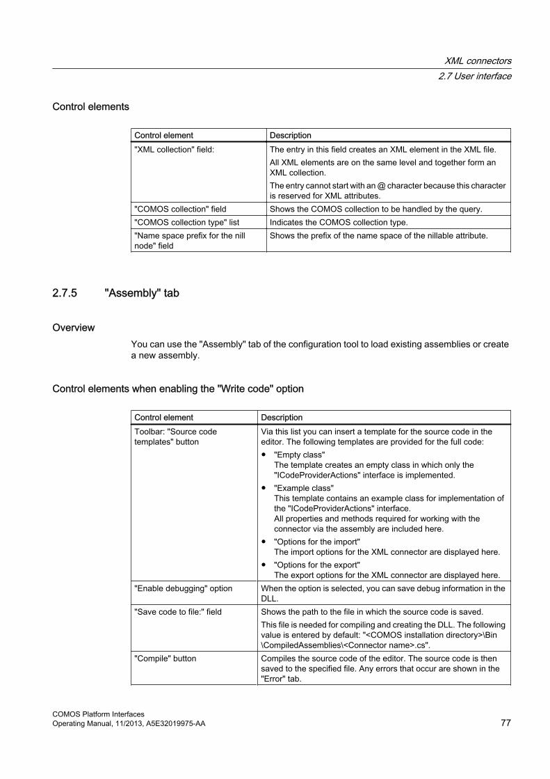
Control elements
Control element Description"XML collection" field: The entry in this field creates an XML element in the XML file.
All XML elements are on the same level and together form an XML collection.The entry cannot start with an @ character because this character is reserved for XML attributes.
"COMOS collection" field Shows the COMOS collection to be handled by the query."COMOS collection type" list Indicates the COMOS collection type."Name space prefix for the nill node" field
Shows the prefix of the name space of the nillable attribute.
2.7.5 "Assembly" tab
OverviewYou can use the "Assembly" tab of the configuration tool to load existing assemblies or create a new assembly.
Control elements when enabling the "Write code" option
Control element DescriptionToolbar: "Source code templates" button
Via this list you can insert a template for the source code in the editor. The following templates are provided for the full code:● "Empty class"
The template creates an empty class in which only the "ICodeProviderActions" interface is implemented.
● "Example class"This template contains an example class for implementation of the "ICodeProviderActions" interface. All properties and methods required for working with the connector via the assembly are included here.
● "Options for the import"The import options for the XML connector are displayed here.
● "Options for the export"The export options for the XML connector are displayed here.
"Enable debugging" option When the option is selected, you can save debug information in the DLL.
"Save code to file:" field Shows the path to the file in which the source code is saved.This file is needed for compiling and creating the DLL. The following value is entered by default: "<COMOS installation directory>\Bin\CompiledAssemblies\<Connector name>.cs".
"Compile" button Compiles the source code of the editor. The source code is then saved to the specified file. Any errors that occur are shown in the "Error" tab.
XML connectors2.7 User interface
COMOS Platform InterfacesOperating Manual, 11/2013, A5E32019975-AA 77

Control elements when enabling the "Load compiled assembly" option
Control element Description"Assembly file" fieldButton "..."
Click the "..." button to open the "Select file" window.Select the file for the compiled assembly.
"Assembly name" field Enter the name of the assembly here."Fully qualified class name" field The assembly can contain a number of classes.
Enter the name of the class loaded by the connector here.
2.7.6 "Error" tab
OverviewThe "Error" tab displays the errors that occur during manual compilation of the C# source code.
2.7.7 "Extras" tab of the column properties
OverviewThe "Extra" tab is for making additional settings for the column properties.
"For MotionX only" control groupThe "For MotionX only" control group provides additional settings that are generally not applicable for queries. These settings relate to the use of XML connector documents.
These settings can be found in the table on the configuration tool's "Mapping" tab.
XML connectors2.7 User interface
COMOS Platform Interfaces78 Operating Manual, 11/2013, A5E32019975-AA

Control element Description"Key columns" option Key columns are used to uniquely identify entries for the query.
The connector document can only import new objects if you have defined key columns. Key columns are used during runtime to synchronize the rows of the COMOS query table with the rows of the XML table.If a row of the COMOS table contains the same key as the XML table, the connector overwrites the entries in the COMOS table with those from the XML table.If the connector cannot find a suitable entry in the COMOS table, it creates a new row and fills it with the XML data.You can define several key columns for a query. Key columns are read only when importing XML data.
"XML type" list You can choose between three entries in this list:● "ID": The XML data type "ID" uniquely identifies XML nodes
within an XML file.● "IDREF": The "IDREF" data type is used in the XML attributes
and sets references between the XML elements.● "Double": The "Double" data type stores the value of the attribute
as a number with decimal places in English format, for example: 2.0. 0 is output if no value is present.
You can use the ID/IDREF method to form COMOS references in XML. You can use an XML connector document to automatically set references between COMOS objects when importing XML data.
"Check column" option The Check column writes information to the Enterprise server.Check columns are always executed at the end of the calculation of a row. When the check column function is executed, all other cell values of this row are available and can be queried.When the Enterprise server started an XML connector, the value of the check column is written to the MXR file, the response file.
"Optional" option The enabled option causes an element in the XML file to not be created when it is empty.
"Nillable" option When this option is enabled, an element can have an empty value. A namespace prefix is assigned to the zero value in the "Mapping" tab of the configuration tool. By default, the value "xsi" is entered in the "Name space prefix for the nill node" field.The result is then "<element xsi:nil="true"/>".
"XML assignment" field: This field shows the assigned XPath expression."Mapping table for values" list Select the required standard table from this list or drag&drop it from
the Navigator."Column with COMOS values" list
This list shows the columns of the standard table selected under "Mapping table for values". The values of the selected column are stored in COMOS.Example: COMOS value: "mm"
"Column with external values" list This list shows the columns of the standard table selected under "Mapping table for values". The values of the column selected here are stored in the XML file.Example: XML value: "Millimeter"
XML connectors2.7 User interface
COMOS Platform InterfacesOperating Manual, 11/2013, A5E32019975-AA 79

You can find additional information on this topic in the "COMOS Platform Operation" manual, keyword "Using queries".
2.7.8 "Script" tab
Display of the "Script" tabIf you have saved or commented out a VB script for an existing connector document, the "Script" tab is displayed. This tab is disabled for newly created connector documents.
Connector documents with a VB script continue to be run with the VB variant of the "Components ComosXMLInterface" connector document.
FunctionBy default, the queries that are located directly below the XML template get their respective COMOS start objects from the XML connector document. The queries subsequently pass their row objects as COMOS objects to the queries that are located below them in the hierarchy.
You have the option of intervening in this sequence using a script.
The top queries directly below the XML template can call the following functions:
● "Master_Export" ● "Master_Import"If there are master methods, they are called.
The following functions are available for all other levels:
● "<"QueryName">_ImportRow"
● "<"QueryName">_ExportRow"
This applies for each row of the running query. If there is a script method, it is called line-by-line. If there is no script method, all underlying queries get the row object of the query currently being executed as the start object.
The CurrentJobWhen the query is processed, the so-called CurrentJob runs. You can then query the following from this object:
● Current query
● OrigCollection of COMOS objects
● XMLNodes at the XML document
XML connectors2.7 User interface
COMOS Platform Interfaces80 Operating Manual, 11/2013, A5E32019975-AA
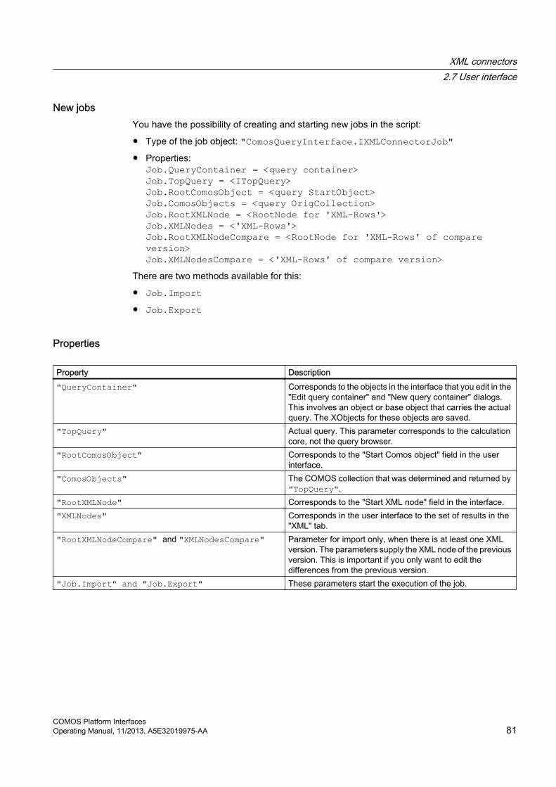
New jobsYou have the possibility of creating and starting new jobs in the script:
● Type of the job object: "ComosQueryInterface.IXMLConnectorJob" ● Properties:
Job.QueryContainer = <query container> Job.TopQuery = <ITopQuery> Job.RootComosObject = <query StartObject> Job.ComosObjects = <query OrigCollection> Job.RootXMLNode = <RootNode for 'XML-Rows'> Job.XMLNodes = <'XML-Rows'> Job.RootXMLNodeCompare = <RootNode for 'XML-Rows' of compare version> Job.XMLNodesCompare = <'XML-Rows' of compare version>
There are two methods available for this:
● Job.Import● Job.Export
Properties
Property Description"QueryContainer" Corresponds to the objects in the interface that you edit in the
"Edit query container" and "New query container" dialogs. This involves an object or base object that carries the actual query. The XObjects for these objects are saved.
"TopQuery" Actual query. This parameter corresponds to the calculation core, not the query browser.
"RootComosObject" Corresponds to the "Start Comos object" field in the user interface.
"ComosObjects" The COMOS collection that was determined and returned by "TopQuery".
"RootXMLNode" Corresponds to the "Start XML node" field in the interface."XMLNodes" Corresponds in the user interface to the set of results in the
"XML" tab."RootXMLNodeCompare" and "XMLNodesCompare" Parameter for import only, when there is at least one XML
version. The parameters supply the XML node of the previous version. This is important if you only want to edit the differences from the previous version.
"Job.Import" and "Job.Export" These parameters start the execution of the job.
XML connectors2.7 User interface
COMOS Platform InterfacesOperating Manual, 11/2013, A5E32019975-AA 81

Examples: Redundant properties● If you enter "QueryContainer" , you do not have to enter the "TopQuery" if it comes
from this container. In this case, it is determined automatically by the "QueryContainer" .
● If you have entered "RootComosObject" and the query is to search for the objects in the standard way, you do not have to enter "ComosObjects" .
● If you want to define the "OrigCollection" yourself in another way, you do not have write "IExtender" for the query. You can here enter the suitable objects as "ComosObjects" properties here.
Example 1This is how the standard case looks like in the script:
Sub Q1_ExportRow(ComosObj, XMLNode) Set QSubs = CurrentJob.QueryContainer.EnObs("J") For i = 1 To QSubs.Count Set NJ = CreateNewJob() NJ.QueryContainer = QSubs.Item(i) NJ.RootComosObject = ComosObj NJ.RootXMLNode = XMLNode NJ.Export Next End Sub Sub Q2_ImportRow(ComosObj, XMLNode, XmlNodeCompare) Set QSubs = CurrentJob.QueryContainer.EnObs("J") For i = 1 To QSubs.Count Set NJ = CreateNewJob() NJ.QueryContainer = QSubs.Item(i) NJ.RootComosObject = ComosObj NJ.RootXMLNode = XMLNode NJ.RootXMLNodeCompare = XmlNodeCompare NJ.Import Next End Sub
Script templates The templates for script methods can be accessed via the "Source code templates" button.
XML connectors2.7 User interface
COMOS Platform Interfaces82 Operating Manual, 11/2013, A5E32019975-AA

2.7.9 "Extras" tab of the column properties
"For MotionX only" control groupAll the properties listed in the "For MotionX only" section can be accessed via the "Mapping" tab. See also chapter "Mapping" tab (Page 76).
2.7.10 "MotionX" window for the export
Overview
Control element Description"File name:" field Here, you select a file or assign a name for a new file. If you select an existing file here,
it will be overwritten."Reference object:" field All calculations and actions of the export are started from this object. The default setting
for the reference object is taken from the "Reference object" field in the "XML document" tab in the properties. If you set another object in the "Reference object" field, this new setting is saved in the "Reference object" field in the "XML document" tab. This also sets the "Query start object" field to a new default, since the field is also controlled by the "Reference object" field.
"Include in version management" option
This option causes the creation of an XML connector document during the export operation. This document is linked via the "File name" field with an XML file that is located in the document directory of COMOS.The option does not affect the version management of PQM.
"Show file" option If this option is activated, the XML file opens with the selected default program when the export is complete.
2.7.11 "MotionX" window for the import
Overview
Control element Description"File name:" field Select the file to be imported here."Reference object:" field All calculations and actions for the preparation of the import
operation start from this object."Delete objects" option When this option is activated, all objects that are present in
COMOS but not in the imported XML file are deleted."Create working layer" option You use this option to create a new working layer and switch
to it. The imported data is created in the new working layer.
XML connectors2.7 User interface
COMOS Platform InterfacesOperating Manual, 11/2013, A5E32019975-AA 83

Control element Description"Include in version management" option This option causes an XML connector document to be
created during the import operation. This document is linked with an XML file located in the document directory of COMOS via the "File name:" field.The option does not affect the version management of PQM.
"Consider different objects only" option This option causes the XML connector to import only the delta. This means that only the differences between the current XML file and the most recently imported XML file are imported.This option first requires at least one import to have been made with the "Include in version management" option. In other words, there must be at least one versioned XML connector document.
"Cancel on error" option If an error occurs with an import the data, all previous changes initiated by the XML connector are discarded. There are restrictions for changes via a script. Imported working layers are not deleted.
"Show file" option If this option is activated, the XML file opens with the selected default program when the import is complete.
XML connectors2.7 User interface
COMOS Platform Interfaces84 Operating Manual, 11/2013, A5E32019975-AA

Standard import "Blank XML" 33.1 Introduction
GeneralThe standard import for XML data is specified for the import of XML data that were not COMOS objects previously.
You can import these external data into COMOS and store them in the form of base or engineering objects. See also chapters Opening the preset standard import (Page 85) and Creating a new standard import (Page 85).
The table import function uses DOM ("MSXML.DOMDocument").
The data is first read into the action and displayed for checking on the screen. The import into the database takes place in a second step, for example, as a unit of new COMOS objects.
You can control the importing process with a script. This script and all other details on a special import process are stored in an archive and can be reused at any time.
3.2 Opening the preset standard import
ProcedureIn the menu bar, select the "Extra > Standard import > XML blank" command.
See also chapter Configuring and carrying out a standard import (Page 86).
3.3 Creating a new standard importIf you want to store multiple import configurations, create multiple new standard import objects under base objects.
Procedure1. Open the base project.
2. Select the "Base objects" tab in the Navigator.
3. Select the object under which you want to create the XML file.
4. Select the "New > New standard import > XML data" command in the context menu.
5. Double-click the newly created object.The "Standard import: XML data" tab opens.
COMOS Platform InterfacesOperating Manual, 11/2013, A5E32019975-AA 85

See alsoConfiguring and carrying out a standard import (Page 86)
3.4 Configuring and carrying out a standard import
RequirementThe "Blank XML" tab or the "Standard import: XML data" tab is open. See also chapters Opening the preset standard import (Page 85) and Creating a new standard import (Page 85).
Procedure1. Select a mode.
"Design mode" is set by default.
– If you want to make configuration settings via a script before importing data from an XML file, click the "Design mode" button.Click the "Open XML file" button and select the XML file. The corresponding XML code is displayed in the lower field.Specify the settings for how the XML data is to be handled in the script area in the form of a VB script.Save the settings of the design mode for the future import of XML data. See also chapter Using saved settings for the import (Page 86).
– If you want to import data from an XML file and not make any changes to the default settings in the process, click the "Run mode" button.If the XML file field is empty or you want to change the field content, click the "Open XML file" button and select the XML file.
2. To carry out the standard import of the XML file, click the "Execute" button.
3.5 Using saved settings for the import
RequirementYou have already made settings for an import. See also chapter Configuring and carrying out a standard import (Page 86).
ProcedureTo call up an import process with the stored settings again, double-click the import object in the Navigator.
Standard import "Blank XML"3.5 Using saved settings for the import
COMOS Platform Interfaces86 Operating Manual, 11/2013, A5E32019975-AA

3.6 Allowing or prohibiting changes to import settings
RequirementThe "Standard import: XML data" or "XML blank" tab is open. See also chapter Configuring and carrying out a standard import (Page 86).
Procedure1. Click the "Administration" button in the "Standard import: XML data" tab.
– If you want to permit changes or storing, activate the "Allow" button.
– If you want to prohibit changes or storing, activate the "Prohibit" button.
– To specify detailed settings click the "Extended" button in the "Administration" window.You can differentiate between operating options via the toolbar or the changing of input values and carry out the settings.
2. Select one of the following options:
– To save the settings, click the "OK" or "Apply" buttons in the "Administration" window.
– To apply the settings permanently, click the "Save" button in the "Standard import: XML data" or "XML blank" tab.
Standard import "Blank XML"3.6 Allowing or prohibiting changes to import settings
COMOS Platform InterfacesOperating Manual, 11/2013, A5E32019975-AA 87


Standard import "Blank table" 44.1 Introduction
You can import external tables into COMOS and store the data of the tables in the form of base objects or engineering objects. Access databases, Excel tables and text files are supported.
The table import function uses ADO ("ADODB.Recordset).
RecommendationUse Access databases as the import source if possible.
Steps for importingAn import consists of the following steps:
1. Open the import sourceOpen a database or a folder. All the tables, spreadsheets and files of the import source are displayed. The selected table is transferred to the display area. You can import one table after the other.
2. View the import dataWhen you double-click a table in the window of the selection area, the data is displayed in the display area. The column designation is used as a column title. The status field at the lower edge of the area indicates the current table and rows and the number of rows (data records) selected. Use the buttons to the right and left of the status field to navigate within the records. Multiple selection is possible.
3. Write the import scriptThe import process is controlled using a script. This script and all other details on a special import process are stored in an archive and can be reused at any time.
4. ExecuteThe import starts for the selected datasets. COMOS data is changed or created.
4.2 Opening the preset standard import
ProcedureIn the menu bar, select the "Extra > Standard import > Blank table" command. See also chapter Configuring and carrying out a standard import (Page 90).
COMOS Platform InterfacesOperating Manual, 11/2013, A5E32019975-AA 89

4.3 Creating a new standard importIf you want to save multiple import configurations, create multiple new standard import objects under base objects.
Procedure1. Open the base project.
2. Go to the "Base objects" tab in the Navigator.
3. Select the object under which you want to create the table data.
4. Select the "New > New standard import > Table" command in the context menu.
5. Double-click the newly created object.See also chapter Configuring and carrying out a standard import (Page 90).
4.4 Configuring and carrying out a standard import
RequirementThe "Blank table" tab or the "Standard import: Table" tab is open. See also chapters Opening the preset standard import (Page 89) and Creating a new standard import (Page 90).
Procedure1. Select a mode.
"Design mode" is set by default.
– If you want to make configuration settings via a script before importing table data, click the "Design mode" button.Select "Access", "Excel" or "Txt file" in the upper field. Click the "Open file" button and select the file. See also chapter Import sources (Page 91).Specify the settings on how the table data is to be handled in the script area in the form of a VB script. See also chapter Script for import actions (Page 93).Save the settings of the draft mode for the future import of table data using the "Save" button. See also chapter .
– If you want to import data from a table and not make any changes to the default settings in the process, click the "Run mode" button.If the "Database" field is empty or you want to change the field content, click the "Open file" button and select the file.
– If you want to specify whether to allow or prohibit the changing of import settings, click the "Administration" button. See also chapter Using saved settings for the import (Page 91).
2. To perform the standard import of the table data, click the "Execute" button.
Standard import "Blank table"4.4 Configuring and carrying out a standard import
COMOS Platform Interfaces90 Operating Manual, 11/2013, A5E32019975-AA

4.5 Using saved settings for the import
RequirementYou have already made settings for an import. See also chapter Configuring and carrying out a standard import (Page 90).
ProcedureTo call up an import process with the stored settings again, double-click the import object in the Navigator.
4.6 Properties of an action objectIf you double-click the objects of the "Action" class, the special interface and not the properties of the object is opened.
Opening the properties of an action object● Properties of a base object: Select the object in the Navigator and select the "Properties"
command in the context menu.
● Properties of an engineering object: You cannot open the properties for engineering objects. You can open the general data of the properties, such as "Name", "Label", "Description", "Base object", in the user interface by clicking the "Properties" button.
4.7 Import sources
4.7.1 Access
Tables and queriesIf you select an Access database, then all Access tables and all Access queries of the selected database are offered for import. COMOS lists all tables and queries, including all table columns, that were found. Information on the type and size is also given for the table columns.
The table or query selected in each case is imported. You can only import tables or queries one after the other.
Standard import "Blank table"4.7 Import sources
COMOS Platform InterfacesOperating Manual, 11/2013, A5E32019975-AA 91

4.7.2 Excel
FormattingExcel spreadsheets must use a header row. The field names are entered in the header row.
If you select an Excel file, all Excel sheets of this file are offered for import. The worksheets are described as "tables" in the import object.
The table or Excel sheet selected in each case is imported. You can only import the tables one after the other.
Note that an error-free import of the data from Excel is only possible if the columns of the Excel table are formatted (number, text) before the first input is made. Otherwise data can be lost during the import. Excel uses formats of its own such as "General". This format is a function that reacts to the inputs and formats the cells in different ways according to the situation. Standardized software products such as SQL, ADO, and TrueDBGrid cannot process such data.
Retrospective changes to the column definition have no effect. If you want to format an Excel table subsequently, you must format each cell individually.
You can also import undefined Excel tables into Access and then open the Access database in the import object.
4.7.3 Text file
Without formatThe text files must be saved without a format. Then structure of the text file depends on the definition within the registry.
Example of the structure of a text file
Field delimiters: SemicolonInclude the field name in the first line: YesText delimiter character: None
ImportThe settings for the ADO import of a text file that are valid for the PC are located in the registry at "\HKEY_LOCAL_MACHINE\Software\Microsoft\Jet\4.0\Engines\Text".
In contrast to Access and Excel, when text files are imported, there is no higher-level file containing individual tables and sheets. Therefore, when importing text files you have the option of selecting a folder and importing all text files of this folder.
The individual text files within a folder are offered as tables in the import object. The table selected in each case is then imported. You can only import the tables one after the other.
Standard import "Blank table"4.7 Import sources
COMOS Platform Interfaces92 Operating Manual, 11/2013, A5E32019975-AA

4.8 Script for import actions
4.8.1 Import script
OverviewEach script contains the following areas:
● "Global"● "Init"● "ImportRow"● "Finish" You can also add your own "Subs" or "Functions" to the script.
4.8.2 Script blocksYou can apply each of the components to the script immediately. See also chapter Applying a script component (Page 96).
The following variables are automatically available:
● "WorkSet" Returns the entire COMOS environment.
● "Project" Returns the current project.
Standard import "Blank table"4.8 Script for import actions
COMOS Platform InterfacesOperating Manual, 11/2013, A5E32019975-AA 93

Components
Component Meaning"Set RootObject = <Object>" <Object> represents any variable name and is filled with an object.
The objects in which the imported data is stored are created below this engineering object. As a rule, the variable is defined in Global and can thus also be redefined in one of the other script components.
"Set RootCObject = <Object>" Root object in the form of a base object. The objects in which the imported data is stored are created below this base object. As a rule, the variable is defined in Global and can thus also be redefined in one of the other script components.Note that it is possible to simultaneously specify a root object for engineering objects with the RootObject command and a root object for base objects with the RootCObject command in one import operation. But only one project can be opened! If engineering and base objects are created simultaneously with the various Set commands, local base objects will be created in an engineering project, for example.
"Set <Object> = NewObject(<RelativeName>, [<Description>])"
Reference object or reference command is Set RootObject<RelativeName>: Name and path defined relative to the root object. The levels of the path are separated with the default delimiter. Example "X|XY": In this case, a node "X" is searched for or created below the root object, and an object with the name "XY" is searched for or created there.<Description>: Optional; sets or overwrites the object description.
"Set <Object> = NewCObject(<RelativeName>, [<Description>])"
Reference object or reference command is Set RootCObject<RelativeName> : Name and path defined relative to the root object. The levels of the path are separated with the default delimiter.Example "X|XY": In this case, a node "X" node is searched for or created below the root object, and an object with the name "XY" is searched for or created there.<Description>: Optional; sets or overwrites the object description.
"Set <Object> = NewSpec(<CObject> , <NestedName>, [<Description>])"
Creates a new attribute and/or a new "Attributes" tab for a base object.● <CObject>: The base object for which new attributes are created.● <NestedName>: The NestedName is the combination of the name of the
"Attributes" tab and the name of the attribute separated by a dot. Example: Chap1.Spec1 is the "Spec1" attribute in the "Chap1" tab.
● <Description>: Optional; sets or overwrites the object description.Note that properties such as the location of the attribute in the tab and size of the attribute cannot be set.
"SpecValue(<SpecOwnerObject>, <NestedName)>) = <vNewValue>"
Sets the value of an attribute or overwrites it.● <SpecOwnerObject>: The object variable of an engineering object or
base object● <NestedName>: Combined name of the tab and the attribute.● <vNewValue>: New value
Standard import "Blank table"4.8 Script for import actions
COMOS Platform Interfaces94 Operating Manual, 11/2013, A5E32019975-AA

Component Meaning"SpecUnit(<SpecOwnerObject>, <NestedName)>) = <vNewValue>"
Sets the unit of an attribute or overwrites it.● <SpecOwnerObject>: The object variable of an object or base object● <NestedName> : Combined name of the tab and the attribute● <vNewValue> : New value
"<Variant> = Field(<FeldName>)" Alternative command to <Variant> = StrFieldFetches information from a special cell of the current row of the imported table.● <Variant>: Variable of the variant type ● <FeldName>: Name of the column (field name) or index of the field, starting
with one."<String> = StrField(<FeldName>)"
Alternative command to <Variant> = FieldFetches information from a special cell of the imported table.● <String> : Variable of the string type● <FeldName> : Name of the column (field name) or index of the field, starting
with zero"OutputDebugString" Supplies output to DBMon."CNameForNewObject(<Index>) = <FullName>"
Specifies a base object for the engineering object that makes up this node. The base object must exist already, the base object could also have been created already at an earlier point in time while the script was running. ● <Index>: Number of the level starting from the root object. In the example
"X|XY": The node "X" has index 1 and the object "XY" has index 2. ● <FullName>: Name and path of the base object relative to the project, e.g.,
"@U|Anl1".As a rule, the variable is defined in Global and can thus also be redefined in one of the other script components.
"If <...> Then...Else...End If"
A standard VBScript routine.Checks whether a condition has the value "True" or "False" in order to execute one or more instructions conditionally.
"Select Case <...>...End Select"
A standard VBScript routine.The routine is activated when Case occurs.
"For i = <...> To <...>...Next"
A standard VBScript routine.This routine is run as often as specified.
"For Each <...> In <...>...Next"
A standard VBScript routine.The routine is run as many times as there are members in this collection.
"Do <...>...Loop"
A standard VBScript routine.The routine is executed until the Do condition is fulfilled and there is a possibility to exit.
"While <...> ...Wend"
A standard VBScript routine.Same as Do ... Loop, but without a possibility to exit.
Standard import "Blank table"4.8 Script for import actions
COMOS Platform InterfacesOperating Manual, 11/2013, A5E32019975-AA 95

See alsoOpening the preset standard import (Page 89)
4.8.3 Applying a script component
Procedure1. Open the standard import. See also chapter Opening the preset standard import
(Page 89).
2. Click the "Help" button in the script area.
3. Double-click a component in the "Script components" tab in the "Script: components, declarations" window.
ResultThe script text is applied. The commented marked as comments are not applied.
4.8.4 "Declarations" tab
DLLsThe "Declarations" tab in the "Script: components, declarations" window shows the functions and properties of DLLs. A number of important DLLs are already entered in the list:
Applies to all DLLs:
You can use drag&drop to apply the last level (functions and properties) in each case to the script.
In addition to the DLLs offered in the list, you can drag any other appropriate DLL into the script field. The corresponding DLL is read in and its functions and properties are offered. The DLL is not permanently saved.
4.8.5 Example
Importing engineering objects
"CNameForNewObject(1) = "MyTest|ABC"""CNameForNewObject(2) = "MyTest|MM"" These two rows ensure that the engineering objects of the first level (Index=1) and the objects of the second level (Index=2) are linked to base objects. The base objects must exist already."ImpObjectsCount = 0"
Standard import "Blank table"4.8 Script for import actions
COMOS Platform Interfaces96 Operating Manual, 11/2013, A5E32019975-AA

Here a counter is initialized to zero."Sub Init()"See also chapter"Set RootObject = Project.Devices.Item("XX3") " Object XX3 is set as the root object in the start routine that is run right at the beginning. XX3 is located directly below the project. All objects that are created subsequently are deposited below this root object. This assumes that XX3 exists already. If XX3 does not exist, an error occurs."End Sub" "Sub ImportRow()""RName = "Imp|" + StrField("CategoryID")" A string is assembled here to supply the node and the name for each object to be created later. The name is made up of two constituent parts: 1. A fixed text part "IMP|": This fixed constituent part supplies the node, under which the object is created 2. The imported text in each case from the cells of the imported table. This variable text serves as the name of the object to be created."Set ND = NewObject(RName, "imported object")" New objects are created. RName was created as a string further above. The text "imported object" is always used as the description."If Not ND Is Nothing Then""ImpObjectsCount = ImpObjectsCount + 1""End If " If the object was created correctly, then the counter from Global is incremented by one."End Sub""Sub Finish()""OutputDebugString CStr(ImpObjectsCount) + " objects imported"""End Sub" The number of imported datasets (= number of created objects) is output in the database monitor."End Sub"
4.9 Tab "Blank table"
Toolbar in Design mode
Button Description"Navigate" Displays the object in the Navigator."Refresh" The special interface is updated."Save / Load" To save the object, click the button. If you click the arrow to the right of the button,
the following commands are displayed: ● "Save": Saves the object, including the archive● "Save as": Duplicates the object, including the archive. The "Save as..."
window opens for this purpose:● "Save to file...": Opens the file selection for the save operation● "Load from file...": You overwrite the current archive● "Load from inheritance source": Determines the inheritance sources
"Properties" Displays the properties of engineering objects.
Standard import "Blank table"4.9 Tab "Blank table"
COMOS Platform InterfacesOperating Manual, 11/2013, A5E32019975-AA 97

Button Description"Administration" Here, you specify to what extent the engineering object of the import may be
changed."Stop at error" The import stops. The extent to which COMOS data is created depends on the
import script. If anything was saved in the script up to this point, then this data is imported.Note: This setting is only taken into account in the case of syntax errors in the script. If errors occur during creation, for example if a COMOS object is not successfully created, this setting is not taken into account.
"Continue at error" For engineering objects, an attempt is made to perform the rest of the import."Design mode" The draft mode opens the corresponding interface. Here, you develop the rules,
which are also later saved in the archive."Run mode" The runtime mode is used to execute an import after concluding all preparatory
work.
Buttons in the script areaIn addition to the standard buttons, the following buttons are available for editing the script.
Button Description"Mark as comment" To mark as a comment, click in the desired line of script and then on this button."Remark comment" To cancel marking as comment, click in the desired line of script marked as
comment and then on this button."Increase indent" To increase the indent of a line, click in the desired line of script and then on
this button."Decrease indent" To decrease the indent of a line, click in the desired line of script and then on
this button."Execute" The import starts for the selected datasets."Cancel" Cancels the triggered import process. The extent to which COMOS data is
created depends on the import script. If you have saved the script up to this point in time, this data is imported.
"Undo COMOS objects"
All COMOS objects that are imported on a test basis in the draft mode are initially temporary. The temporary objects can be saved manually or are saved automatically in specific situations, such as when the properties are opened. For objects that have not already been saved, this function undoes all changes that were created in the course of a test import. Newly created objects are deleted.
"Save COMOS objects"
All COMOS objects that are imported on a test basis in the draft mode are initially temporary. The temporary objects are saved manually with this command. If you save objects using this method, you can no longer undo the changes with this button.
"Apply example" A fully usable example for an import that can actually be run is called. All entries made previously for the import are discarded.
Help Use this button to open the script help. See also chapter Script blocks (Page 93).
Standard import "Blank table"4.9 Tab "Blank table"
COMOS Platform Interfaces98 Operating Manual, 11/2013, A5E32019975-AA

Engineering projects 55.1 Importing a project
Requirement● The project is imported from a second database.
● The hierarchy of the standard tables is identical. Different hierarchical structures of standard tables can result in inconsistencies. In that case, the "Object test" tab opens automatically.
Procedure1. Select the "File > Open project" command in the menu bar.
2. Select the "Import" command from the context menu of a project.
3. In the "Import project" window, select the source database from which you want to import a project.
4. Check whether you have the necessary rights for this operation for both databases.
5. Click "Next >".
6. In the "Import project" window, select the project you want to import.
7. In the "link with base project:" table, select the base project that is to be assigned for the engineering project.
8. Click on the "Import" button.
See also chapter Exporting a project (Page 99).
5.2 Exporting a project
Requirement● The project is not linked to a base working layer.
● The project is exported to a second database.
Procedure1. Select the "File > Open project" command in the menu bar.
2. Select a project in the upper list.The "Open project" tab lists the projects in the upper list. The lower list contains the working layers for which a separate "Export" function is available.
COMOS Platform InterfacesOperating Manual, 11/2013, A5E32019975-AA 99

3. Select the "Export" command in the context menu of the project.
4. Acknowledge the warning.
5. In the "Export to" window, select the database to which you want to export the project.
6. Confirm the message.
See also chapter Importing a project (Page 99).
Engineering projects5.2 Exporting a project
COMOS Platform Interfaces100 Operating Manual, 11/2013, A5E32019975-AA

Data exchange with NOXIE 66.1 Purpose of NOXIE
Plugin "Native object XML import export"The "Native Object XML Import Export" (NOXIE) plugin writes specified branches of the structure tree to an XML file. The documents are taken along and their files are maintained. This is how base objects, engineering objects, and documents from a source database can be transferred to another database.
The following information is acquired:
● Objects
● Tabs
● Attributes
● Standard tables of the attributes
This information is copied into the target database in its correct structure. If these structures do not exist in the target, they are reproduced and only then the information is copied. The interface also works between working layers and supports import and export operations.
See alsoExchanging data via the NOXIE plugin (Page 101)
Structure of the generated XML file (Page 103)
6.2 Exchanging data via the NOXIE plugin
Procedure1. Select the command "Plugins > Basic > Native Object XML Import Export" on the menu
bar.The "Native Object XML Import Export" tab opens.
2. Select one of the following options:
– To export, select the "Export" option in the "Options" control group.
– To import, select the "Import" option in the "Options" control group.
3. Click on the "..." button next to the "XML Import / Export file" field and select an XML file
4. To select a directory, click on the "..." button in the "Document directory" field and select the required directory.COMOS automatically creates a document folder called "documents" parallel to the XML file after the selection. The processed documents are saved or searched in this directory.
COMOS Platform InterfacesOperating Manual, 11/2013, A5E32019975-AA 101

5. If "Export" has been activated:
– Drag one or a number of objects from the Navigator and drop them into the "Object(s) to export" field.During the export all start objects and all objects lying below are exported.
– To delete one or all objects from the "Object(s) to export" field, mark an object and click on "Remove" or "Remove all" in the context menu.
– If you enable the "Own properties only" option, only the information about the engineering objects that has been checked in is exported. This has no effect for base objects. Please note that in COMOS, a great deal of information is only inherited. For example, the default information from base objects is inherited in many engineering objects. If this option is activated, the inherited values are not processed.
6. If "Import" has been activated:
– Drag&drop an object from the Navigator into the "Drag&drop a start object to import" field. During the import, the objects to be created are created below this start object.
– To delete the start object from the "Drag&drop a start object to import" field, click the "Remove pointer" button next to the field.
– If you enable the "Update" option, only objects that have changed are processed. Not all information is replaced. The timestamp changes.Use the option only when re-importing identical data. All changed and, therefore, new data is taken over into the target directory without an evaluation.
7. If you enable the "With owner info" option, the information about the owner structure is included.
8. Click the "Start export" or "Start import" button.
ResultExport:
● The XML file is created. The documents including external documents are collected in the "documents" folder.
● When you send the XML file, please include the "documents" folder; if you do not, the documents will be empty.
Import:
● All objects are created together below the selected node. The references are set subsequently. A requirement is that the referenced object was also exported.
● Since all data is initially imported below a shared node, copy and move the units and locations to the right positions.
See alsoPurpose of NOXIE (Page 101)
Structure of the generated XML file (Page 103)
Data exchange with NOXIE 6.2 Exchanging data via the NOXIE plugin
COMOS Platform Interfaces102 Operating Manual, 11/2013, A5E32019975-AA

6.3 Structure of the generated XML file
Reference of the XML nodes ● COMOS collections
XML nodes on a device:
– "Elements"– "Connectors"– "Specifications"– "OwnDocuments"All connections that are not empty are written out.You can find additional information on this topic in the "COMOS.dll" class documentation, keyword "OwnCollections".
● ReferencesXML node "References" Contains the references.You can find additional information on this topic in the "COMOS.dll" class documentation, keyword "Reference".
● TranslationsXML node "InternationalDescriptions"Contains the object description in all languages. The "Index" is the index from COMOS language management. If German is selected as the primary language, it has the index "1".
● Owner informationXML node "ObjectOwnerInfo"Contains the information about the owner structure.
Inherited objectsInherited objects and objects below them are not exported or imported. However, since these objects are required in certain cases by NOXIE, they are also contained in the XML file. They are not counted during importing and exporting.
See alsoExchanging data via the NOXIE plugin (Page 101)
Data exchange with NOXIE 6.3 Structure of the generated XML file
COMOS Platform InterfacesOperating Manual, 11/2013, A5E32019975-AA 103


COMOS document interface 77.1 Introduction
Automated exportIn the "COMOS document interface" tab, you can automate the export of COMOS data to Word and Excel documents. You can adapt the layout of these exported documents to the corporate design, archive the exported documents with additional documents or pass on the exported documents externally.
In addition, you can reimport data edited in Excel back to COMOS.
See also chapter Using a COMOS document interface (Page 105).
7.2 Requirements
Installed Microsoft Office products● Word 2000 to 2010
● Excel 2000 to 2007
Settings for Word The display of the field functions is deactivated.
7.3 Using a COMOS document interface
WorkflowThe following list provides an overview of the steps you perform in order to export data from COMOS to an Office document, edit it there, and, if necessary, reimport it back to COMOS:
1. Create the Office document in COMOS. See also chapter Creating an Office document (Page 106).
2. If necessary, open the Office document and prepare it.For Word documents, create the DocVariables. See also chapter Preparing Office documents (Page 106).
COMOS Platform InterfacesOperating Manual, 11/2013, A5E32019975-AA 105

3. To open the document interface, select the "Plugins > Basic > Document interface" command in the menu bar. See also chapter Working in the "Document Interface" tab (Page 107).
4. Use drag&drop to move the Office document to the "Document" field in the "Document interface" tab.
5. Write the CDI script.
6. Check the result of the script in the preview window.
7. Save the script.
8. Close the "Document interface" tab.
9. Open the Office document.This starts the export.
ExcelYou can start a reimport to COMOS by closing the document.
7.3.1 Creating an Office document
Procedure1. In the Navigator, select the object under which the document is to be located.
2. From the context menu, select the "New > General > New Document" command.
3. Enter a name and a description for the document in the properties of the document.
4. Select one of the following entries from the "Type" list in the "General" tab.
– "Word"
– "Word document 2007"
– "Excel"
– "Excel table 2007"
5. Save your changes.
You can find additional information on this topic in the "COMOS Platform Operation" manual, keyword "General documents".
7.3.2 Preparing Office documentsNo preparations are required for Excel spreadsheets. If the spreadsheet specified in the CDI script does not exist at the time of the import operation, it is created automatically..
COMOS document interface7.3 Using a COMOS document interface
COMOS Platform Interfaces106 Operating Manual, 11/2013, A5E32019975-AA

Procedure1. Open the Word document from COMOS.
2. In Microsoft Word, open the options and activate the field functions.
3. Enter the DocVariables in the areas of the document in which you later want to output the COMOS data:
– Place the cursor at the desired location in the Word document.
– Click the "Quick Parts" button in the "Text" control group in the "Insert" tab and select the menu command "Field".
– Select the list entry "Document Automation" and select "DocVariable" as field name.
– In the "New name" field, enter the name of the DocVariable.All DocVariables must have unique names. It is not possible to generate DocVariables dynamically during an export operation.
– Click "OK".The DocVariable is pasted into the document at the location of the mouse cursor:
4. If the COMOS data is to be output in a table, create a table containing the desired columns before inserting the DocVariables. Enter the DocVariables in the table cells.
5. Disable the display of field functions once again.
6. Save.
Note
The technical data of all components below a common owner is to be output. The corresponding number of DocVariables is created in the Word document. If you then create additional components below the owner and perform an import, the new components are not taken into consideration in the import because the corresponding DocVariables are missing in the Word document.
7.3.3 Working in the "Document Interface" tab
Procedure1. Select the "Plugins > Basic > Document Interface" command in the menu bar.
The "Document Interface" tab opens.
2. Ensure that the "Document" field in the "Document interface" tab is filled.This field contains the document link to the document into which the import will be made or for which a script will be written.
– If the Document" field is empty, use drag&drop to move the document from the Navigator into the "Document" field. You can only use Excel and Word documents.
– If the "Document" field is already filled, a document was already selected before the command "Plugins > Basic > Document Interface" was called in the Navigator.
COMOS document interface7.3 Using a COMOS document interface
COMOS Platform InterfacesOperating Manual, 11/2013, A5E32019975-AA 107

3. Set the desired behavior for each script.
– The toolbar contains the standard tools for script editors.
– You implement the CDI script Sub DoCDI() in the script editor. It defines which COMOS data is to be written to the Office document and where it is to be output.
– You can call up all public properties and methods from ComosXMLContent.SCGlobal in the script.
– As is the case for attributes, CDS scripts may not contain pipe characters ("|").
– In addition, all usual COMOS default script commands are available to the user. You can find additional information on this topic in the "Class Documentation COMOS_dll" manual.
– Example:
COMOS document interface7.3 Using a COMOS document interface
COMOS Platform Interfaces108 Operating Manual, 11/2013, A5E32019975-AA

4. To test the script entered in the script editor, click the "XML converter" button.The result of the script is output in the preview window. Two view modes are available.
– Tree view:
– XML view:
5. To save the script, click "OK".The script is run. If no error occurs, the script is saved.
COMOS document interface7.3 Using a COMOS document interface
COMOS Platform InterfacesOperating Manual, 11/2013, A5E32019975-AA 109

Result
The script is saved in the XValue(1) of a hidden attribute at the document.
No automatic acceptance of OLE objects for ExcelSimilar to options and lists, OLE objects are not created automatically. To export these to Excel, create them manually in the Excel file and link them with the corresponding COMOS values.
7.3.4 Special features for WordOnly the writing of values from COMOS to Word is supported. The values are written to document variables created in the Word document. Changes to Word documents cannot be reimported.
Carrying out preparations● Create a Word document in COMOS and open it.
● Activate the display of field functions and insert DocVariables. Recommendation: Enter a combination of column title and line index as the name of the DocVariables.
Example
COMOS document interface7.3 Using a COMOS document interface
COMOS Platform Interfaces110 Operating Manual, 11/2013, A5E32019975-AA

Script
Result in Word
See alsoWorking in the "Document Interface" tab (Page 107)
7.3.5 ExportWhen you open an Office document, the script of the document is run automatically. The data is exported from COMOS to the Office application.
You can edit the data in Office. Note that only Excel tables offer the option to reimport into COMOS.
Export to WordThe content of the Word document changes when values are exported to Word.
Other changes, such as reformatting or the insertion of macros, are not made.
If the DocVariables addressed in the script do not exist in the Word document, no data is exported.
The exported data is only displayed in the document if the field codes in the document are not displayed
Export to ExcelIf the spreadsheet that is addressed in the script does not exist, it is created dynamically. The data is written into the specified cells of this spreadsheet.
If the exported data include an attribute that is stored with a list, the cell in Excel is also stored with a list. All values of the list are available.
COMOS document interface7.3 Using a COMOS document interface
COMOS Platform InterfacesOperating Manual, 11/2013, A5E32019975-AA 111

If the exported data include an attribute of the type "Checkbox", a check is carried out whether it is a check box or an option group. A check box or an option is then inserted in the table accordingly.
7.3.6 Reimport
Method Content()If the data were exported to Excel using the Content() method, the Excel file is reimported to COMOS once you have closed it. The values edited in Excel are automatically written back to the COMOS objects if the IO parameter of the Content() method has the value I.
7.3.7 Macros
ExcelWhen you open or close an Excel document, COMOS calls special macros for the COMOS document interface, if these are implemented.
You can adapt the macros for every worksheet. In most cases, however, it is sufficient for the macros to be available in ThisWorkbook and to recur in the worksheets.
The following macros are available:
OnBeforeCdiToDocumentPublic Sub OnBeforeCdiToDocument(ByVal comosDocument As Object, ByVal reportObject As Object)This method is called when the document is opened and before COMOS starts the data transfer.
Parameter Description comosDocument (IComosDDocument)
IComosDDocument with DocumentType.ProgramName = "ComosIDocExcel.IDocExcel" is opened
reportObject (IComsoBaseObject)
Report object of the document
You can use this macro in order to prepare the data export from COMOS to Excel, for example, if old contents are to be deleted.
OnAfterCdiToDocumentPublic Sub OnAfterCdiToDocument(ByVal comosDocument As Object, ByVal reportObject As Object)
COMOS document interface7.3 Using a COMOS document interface
COMOS Platform Interfaces112 Operating Manual, 11/2013, A5E32019975-AA

This macro is called after COMOS has transferred the data to the Excel workbook and before the workbook is displayed.
Parameter Description comosDocument (IComosDDocument)
IComosDDocument with DocumentType.ProgramName = "ComosIDocExcel.IDocExcel" is opened
reportObject (IComsoBaseObject)
Report object of the document
You use this macro in order to prepare the display of the document, for example, if empty worksheets are to be hidden.
OnBeforeCdiToComosPublic Sub OnBeforeCdiToComos(ByVal comosDocument As Object, ByVal reportObject As Object)This method is called when the workbook is closed and before the data is transferred from the workbook to COMOS. The workbook is no longer visible at this time.
Note
This macro is not supported in the ThisWorkbook code module.
Parameter DescriptioncomosDocument (IComosDDocument)
IComosDDocument with DocumentType.ProgramName = "ComosIDocExcel.IDocExcel" is opened
reportObject (IComsoBaseObject)
You can use this macro in order to prepare data for reimport, for example, if you delete content of cells you do not want to reimport.
Excel standard macrosIf you use the COMOS document interface, do not use the following standard Excel macros since they are called more than once as part of the evaluation process.
● Workbook_Open● Workbook_BeforeClose
● Workbook_BeforeSave
COMOS document interface7.3 Using a COMOS document interface
COMOS Platform InterfacesOperating Manual, 11/2013, A5E32019975-AA 113

7.4 Reference of the script functions
7.4.1 Reference of the programming interface
MethodAs soon as the CDI plugin is initialized with a document, the following method appears in the Editor window:
Sub DoCDI()End SubThis method is started automatically when evaluating the document if a CDI script was saved in the document (in the "XValue(1)" of a hidden attribute). In this method the user can input his own script.
All public properties and methods from "ComosXMLContent.SCGlobal" are made available to the user in the script.
7.4.2 Properties
Overview
Property Declaration DescriptionDocuments "Public Property Get Document() As
IComosDDocument"Returns the underlying COMOS document.
MappingTableExcel "Public Property Get MappingTableExcel() As IMappingTableEx"
Only set if there is a MappingTableEx below the document.
Project "Public Property Get Project() As IComosDProject"
Returns the current project.
ReportObject "Public Property Get ReportObject() As IComosBaseObject"
If a ReportObject was set at the document, this is returned; otherwise, the owner of the COMOS document is returned.
Workset "Public Property Get Workset() As IComosDWorkset"
Returns the workset.
COMOS document interface7.4 Reference of the script functions
COMOS Platform Interfaces114 Operating Manual, 11/2013, A5E32019975-AA

7.4.3 Function: ExcelABC
General
Declaration Description"Public Function ExcelABC() As String" Enables the conversion of a number into its equivalent as a
column name. This method can be helpful if you iterate collections via an index. You can thus determine the index of the column name with the help of the "ExcelABC()" function.
7.4.4 Function: Content
General
Declaration Description"Public Sub Content(ByVal DocPointer As String, "" ByVal ComosObject As IComosBaseObject, "" ByVal PropName As String, "" ByVal PropParameter As Variant, "" ByVal PhysUnitLabel As String, "" ByVal IOMode As String, "" Optional ByVal AllValuesNumeric As Boolean)"
Depending on "IOMode", data is exported from COMOS into Office, imported from Office into COMOS or exported and reimported using "Content()"."Content()" can also be used for Word documents. However, since these only support the exporting of data from COMOS, the more simple "ContentFix()" function can also be used for Word files.
Parameters
Parameter Description"DocPointer" Specifies at which position in the document the value is to be written and/or from which
position the value is to be written back to COMOS.● Excel:
Specify the spreadsheet and the cell here:"Spreadsheet name!cell name", for example, "Spreadsheet1!B9".If the specified spreadsheet does not yet exist, then it is created.
● Word:Enter the name of the DocVariables here, for example, "volume".It is not possible to write this data back to COMOS.Unlike with Excel, the specified DocVariable is not created if it does not yet exist.
"ComosObject" The object from which the value of a property is to be queried or to which the value is to be written back(normally the "Specification" SystemType, although other SystemTypes are possible).
COMOS document interface7.4 Reference of the script functions
COMOS Platform InterfacesOperating Manual, 11/2013, A5E32019975-AA 115

Parameter Description"PropName" Determines which "ComosObject" property is to be read in or out. Either a property
or a function of the "ComosObject" is passed (for example, "Name", "GetDisplayValue", "GetXValue", etc.).
"PropParameter" If a method was passed using the "PropName" method, a parameter can here be specified for the queried propertyFor example, if you want to query "ComosObject.GetXValue(0)" via a CDI script, this would look as follows:Content "Table1!C2", ComosObject, "GetXValue", 0, "", "IO", False
"PhysUnitLabel" Physical unit of the value returned by "PropName" in the form of a string. The value is converted into the unit specified in "PhysUnitLabel" and then passed to Excel as a number. This means that the cell gets the "Numeric" format. The value can then be used in Excel for further calculations.The specified unit must originate from the units group that was set at "ComosObject". Otherwise, the current unit of the COMOS attribute is used automatically.Empty string: No unit is passed.
"IOMode" Specifies in which direction the data is to be written:● "I": Only supported by Excel. Data is written from Excel to COMOS● "O": Supported by Excel and Word. Data is written from COMOS to Word or Excel.● "IO" or "": A combination of "I" and "O". Only supported by Excel.
"AllValueNumeric" Optional parameter. Specifies if an attempt is to be made first of all to interpret the value that is to be written as a numeric value.This parameter is extremely relevant to Excel. For example, it may be that an alphanumeric attribute only contains numbers. If you were to write these values to Excel as a string, you would no longer be able to use them to make any calculations.
7.4.5 Function: ContentFix
General
Declaration Description"Public Sub ContentFix(ByVal DocPointer As String, "" ByVal vNewValue As Variant, "" Optional ByVal AllValuesNumeric As Boolean)"
This method is a simplified variant of the "Content()" method. It can only be used to export values from COMOS. It is not possible to write back the values. Since only the value that is to be output is passed but the information about which object and which property this value belongs to is missing, numeric attributes cannot be detected automatically. Therefore, each value is formatted as a string in Excel by default. Only through the last optional parameter you have the option to force the formatting to be numeric.
COMOS document interface7.4 Reference of the script functions
COMOS Platform Interfaces116 Operating Manual, 11/2013, A5E32019975-AA

Parameter
Parameter Description"DocPointer" In the same way as for "Content()", the position where the value is to be written to
within Office is specified here."vNewValue" The to be written value value."AllValuesNumeric" Specifies if the value should be interpreted as a number.
COMOS document interface7.4 Reference of the script functions
COMOS Platform InterfacesOperating Manual, 11/2013, A5E32019975-AA 117


SAP interface 88.1 Introduction
UseThe COMOS SAP interface enables the communication between COMOS objects and the SAP Maintenance modules, Material Management and Document Management modules. You can use the COMOS SAP interface to export business objects from COMOS to SAP or to import business objects from SAP to COMOS.
SAP has a number of interface technologies which allows data to be exchanged with other systems. Of these various technologies, COMOS uses BAPI (Business Application Programming Interface) and RFC (Remote Function Call). BAPI is a standardized programming interface that allows you to access the business objects of SAP.
The following modules and business objects are supported by the COMOS SAP Interface:
● Maintenance
– Functional locations
– Equipment
● Material Management
– Materials
– Bills of materials
● Document Management
– Documents
● Classification
– Classes
– Mapping of objects
● Additional modules
– User-defined data communication
The SAP interface of COMOS is not statically based on specific BAPIs and RFCs, meaning that you can specify for yourself in COMOS which RFCs you wish to use.
See also chapter Administering the SAP interface (Page 120).
COMOS Platform InterfacesOperating Manual, 11/2013, A5E32019975-AA 119

8.2 Using the SAP interface
8.2.1 Requirements
Requirements for use● You have basic expertise in the use of XML connectors. See also chapter XML
connectors (Page 43).
● You can operate SAP reliably.
● SAP is installed on your desktop.
● You have access to the SAP server.
8.2.2 Exporting or importing SAP Business ObjectsSAP Business Objects are exported and imported using XML connectors. See also chapter XML connectors (Page 43).
ProcedureSelect one of the following options in the context menu of the XML connector:
● If you want to perform an export, select the "XML > Export" command.
● If you want to perform an import, select the "XML > Import" command.
8.3 Administering the SAP interface
8.3.1 Requirements
Required basic expertiseYou have basic expertise in the following areas:
● COMOS customizing
● Visual Basic Script
● XML connectorsSee also chapter XML connectors (Page 43).
You can also operate SAP reliably.
SAP interface8.3 Administering the SAP interface
COMOS Platform Interfaces120 Operating Manual, 11/2013, A5E32019975-AA

Technical requirements● SAP is installed on your desktop. COMOS supports the SAP GUI for Windows Version 6.4
and later with Unicode RFC libraries.
● You have access to the SAP server.
8.3.2 Architecture of the COMOS SAP Interface
Sequence1. At the COMOS end, an XML connector searches for a set of COMOS objects and generates
an XML file from this.
2. This XML file is passed to a DLL, the so-called SAP Broker.
3. The SAP Broker communicates with the SAP standard interface and converts the XML file into concrete function calls.
4. The results of the function calls are written to the XML file and transported to COMOS using the XML connector.
Access management of the relevant XML filesThe SAP adapter generates the following XML files for the purpose of data communication between COMOS and SAP:
● An XML file for sending data from COMOS to SAP
● An XML file for the data returned by SAP
Only one user of the same SAP adapter can access the same file at any given time.
To prevent multiple users from simultaneously accessing the same XML file for data communication with SAP, the user name is appended to the file name, when this file name is generated automatically. In this way, a separate file is created for each user.
SAP interface8.3 Administering the SAP interface
COMOS Platform InterfacesOperating Manual, 11/2013, A5E32019975-AA 121

8.3.3 User and password management
In COMOS, a connection with SAP is established using login objects.
COMOS does not allow multiple users to use the same user and password data for a login object when establishing a connection with SAP.
Each user only sees the data that corresponds to the current COMOS user and can only change this data. Similarly, only the user and password data of the current COMOS user is used if the SAP system login takes place in the background.
The login objects are located on the "Base objects" tab under "@20 > C80 > Y30 > A10 Login objects". See also chapter "SAP" tab (Page 167).
SAP NetWeaver Single Sign-onYou can set the login to SAP with PKI card in the properties of the login object. One certificate is required per user for secure login with the card. Install SAP NetWeaver Single Sign-on in addition for the Secure Login Client. Ensure that the Windows environment variables of your SAP installation exist.
NoteEnterprise Server
The COMOS Enterprise Server does not support logging in with the PKI card.
Copying and inheriting login objectsIf you have saved user and password data for a login object, this data is only valid for this object or copies of it, not for login objects which are inherited.
Downward compatibilityLogin objects at which user and password data was stored using earlier COMOS versions continues to be supported as usual and is used to establish connections. If you act to save your user and password data for this object while data that were saved with an earlier version are still present, a prompt appears immediately informing you that the system will use the new method to save the data.
You are asked if you want to perform this step. If you confirm this, the old data is deleted and the new data is saved with the current method. From then on, user and password data for this object will be stored separately for every user.
8.3.3.1 SAP target systems
OverviewFor login purposes, you manage a personal list of SAP target systems. In addition to storing the actual connection data, you also have the option of storing a user name and password for
SAP interface8.3 Administering the SAP interface
COMOS Platform Interfaces122 Operating Manual, 11/2013, A5E32019975-AA

logging in to each specific target system. See also chapter Creating an SAP target system (Page 123).
As soon as you log in to the SAP system, the COMOS standard SAP interface starts data communication via this connection. See also chapter Logging in to the SAP target system (Page 123).
8.3.3.2 Creating an SAP target system
Procedure1. In the menu bar, select the "Plugins > SAP > SAP login" command.
See also chapter "SAP login" tab (Page 165).
2. Click the "New" button in the "SAP login" tab.
3. Enter the properties of the SAP target system. See also chapter "Properties" window for the SAP target system (Page 166).The "Client", "Application server", and "System number" fields are mandatory.
4. Save your entries.
8.3.3.3 Logging in to the SAP target system
RequirementAn SAP target system has been created.
Procedure1. In the menu bar, select the "Plugins > SAP > SAP login" command.
2. Select an SAP target system from the list.
3. Click the "Login" button.The "SAP login data" window opens.
4. Enter your user name and password.
5. To save your data so that it is there for you the next time you want to log in to COMOS, activate the "Remember login data for next COMOS session" option.
6. Click "OK".
See also chapter "SAP login" tab (Page 165).
ResultThe connection remains active until you log off again or close COMOS. The current connection status is displayed in the COMOS status line.
SAP interface8.3 Administering the SAP interface
COMOS Platform InterfacesOperating Manual, 11/2013, A5E32019975-AA 123

The COMOS standard SAP interface uses this connection to exchange data for as long as the connection remains active. This means that the connection takes priority over any locally defined connections, e.g. an SAP adapter. In particular, the following areas are affected:
● SAP adapter (SAP XML connectors)
● SAP manufacturer device catalogs and the associated query extender class required to create these catalogs (Comos.Sap.Xml.SapCatalogQueryExtender class)
● Script-based interface calls that involve the Comos.Sap.Xml.ComosSapExchanger class
8.3.3.4 Logging in to the SAP target system with a PKI card
RequirementThe following settings are required depending on the login mode:
● If you select the "Standard" login mode, the settings for Secure Network Communication have to be activated in the login object properties on the "SAP" tab. See also chapter "SAP" tab (Page 167).
● If you select the "File saplogon.ini" login mode, the data has to exist in the "saplogon.ini" file. See also chapter Establishing an SAP connection using the "saplogon.ini" file (Page 139).
Procedure1. In the menu bar, select the "Plugins > SAP > SAP login" command.
2. Ensure that your PKI card is inserted in the card reader.
3. Select an SAP target system from the list.
4. Click the "Login" button.
5. Enter the PIN for your card and click "OK".
8.3.4 Checking the SAP interface configuration
8.3.4.1 General
SAP interface configurationYou can check the SAP interface configuration with the help of a configuration assistant. In so doing, you check the COMOS objects involved in data communication with SAP:
● Login objects
● XML connectors
● Queries
SAP interface8.3 Administering the SAP interface
COMOS Platform Interfaces124 Operating Manual, 11/2013, A5E32019975-AA

● SAP interface objectsThese objects contain all the data to be exchanged with SAP.
● RFC objectsSAP function modules involved in data communication are saved for these objects.
Definition of login objectIn COMOS, you can use login objects to establish a connection with SAP. You store the data required to log in to an SAP system at the login objects, so you do not need to enter it anew each time a connection is established. The login objects are located on the "Base objects" tab under "@20 > C80 > Y30 > A10 Login objects".
If SAP XML connectors are used, the connector itself acts as a login object, as the login data is stored at the connector directly.
Definition of SAP interface objectThe SAP interface objects are used for data communication between COMOS and SAP. The data of a COMOS object, such as an engineering object or a document, is not exchanged with SAP directly; rather, this data is exchanged indirectly via an associated SAP interface object. This SAP interface sends and receives the values assigned to the parameters of the RFCs (Remote Function Calls) during data communication with SAP. To facilitate this, the SAP interface object is located directly below the associated COMOS object in the form of an element. Values are transferred from the COMOS object to the SAP interface object using COMOS attributes at the SAP interface object, which have the link type "By owner". Unlike an RFC object, which only specifies the names of the RFC parameters used, an SAP interface object contains the actual values for these parameters.
Definition of RFC objectYou can use RFC objects to define which RFCs (Remote Function Calls) are called during data communication with SAP and which RFC parameters are used in this process. An individual workflow is followed, according to the type of SAP business objects being exchanged and the type of the exchange process itself (import or export). The individual workflows are defined in the descriptions of the respective SAP modules. Only the names of the RFC parameters are stored at the RFC objects. When data is exchanged, the actual values of the parameters are read from the corresponding SAP interface objects.
8.3.4.2 Opening the SAP interface configuration
Procedure1. Click the "Plugins > SAP > SAP interface configuration" menu command.
2. Select the action you want to carry out.
– "Test SAP connection"
– "Check XML connector configuration"
3. Click "Next >".
SAP interface8.3 Administering the SAP interface
COMOS Platform InterfacesOperating Manual, 11/2013, A5E32019975-AA 125
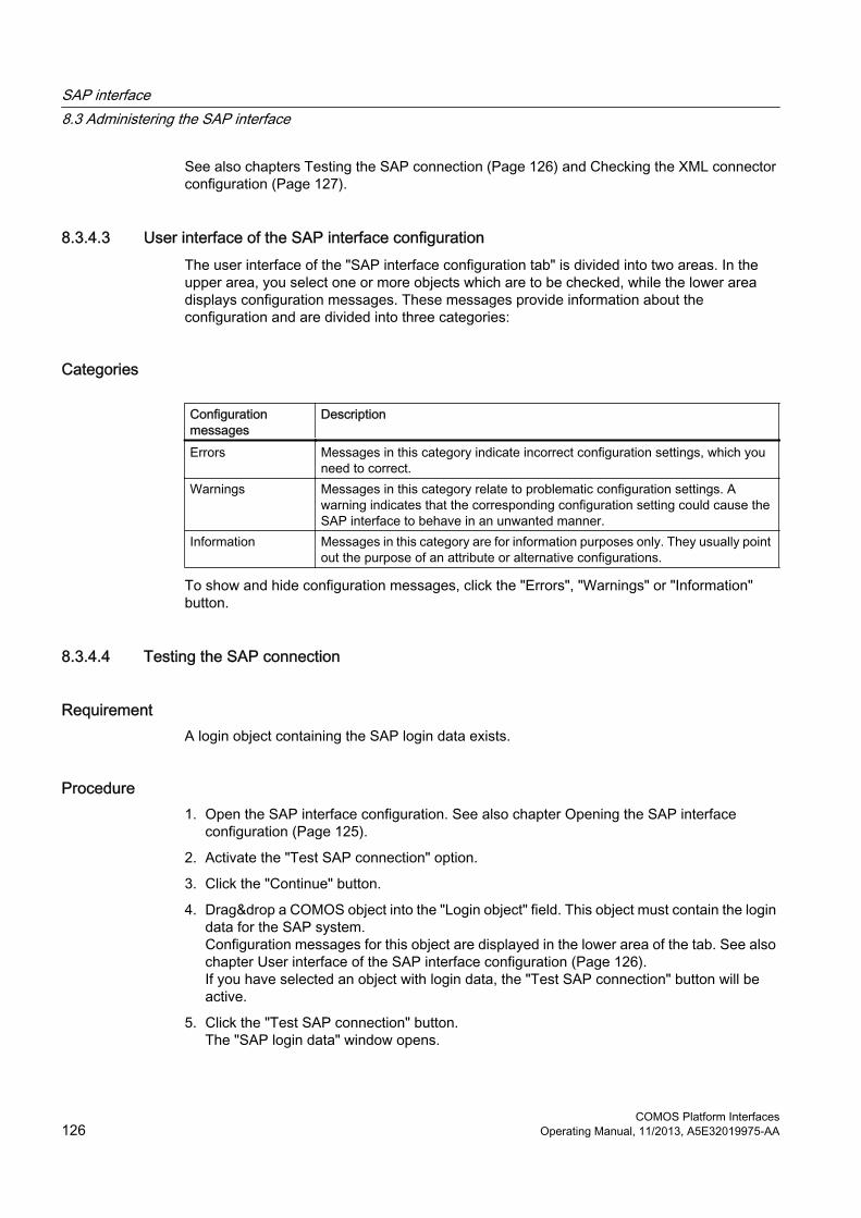
See also chapters Testing the SAP connection (Page 126) and Checking the XML connector configuration (Page 127).
8.3.4.3 User interface of the SAP interface configurationThe user interface of the "SAP interface configuration tab" is divided into two areas. In the upper area, you select one or more objects which are to be checked, while the lower area displays configuration messages. These messages provide information about the configuration and are divided into three categories:
Categories
Configuration messages
Description
Errors Messages in this category indicate incorrect configuration settings, which you need to correct.
Warnings Messages in this category relate to problematic configuration settings. A warning indicates that the corresponding configuration setting could cause the SAP interface to behave in an unwanted manner.
Information Messages in this category are for information purposes only. They usually point out the purpose of an attribute or alternative configurations.
To show and hide configuration messages, click the "Errors", "Warnings" or "Information" button.
8.3.4.4 Testing the SAP connection
RequirementA login object containing the SAP login data exists.
Procedure1. Open the SAP interface configuration. See also chapter Opening the SAP interface
configuration (Page 125).
2. Activate the "Test SAP connection" option.
3. Click the "Continue" button.
4. Drag&drop a COMOS object into the "Login object" field. This object must contain the login data for the SAP system.Configuration messages for this object are displayed in the lower area of the tab. See also chapter User interface of the SAP interface configuration (Page 126).If you have selected an object with login data, the "Test SAP connection" button will be active.
5. Click the "Test SAP connection" button.The "SAP login data" window opens.
SAP interface8.3 Administering the SAP interface
COMOS Platform Interfaces126 Operating Manual, 11/2013, A5E32019975-AA

6. Enter the user name and password for the SAP connection.
7. Click "OK".COMOS attempts to establish a test connection with the SAP system. A window opens and indicates whether or not it was possible to establish the connection.
8. If the connection was established successfully, click "Next >".
9. Click the "End" button to save your changes and close the configuration assistant.
8.3.4.5 Checking the XML connector configuration
Specifying the direction of data communicationThe SAP interface configuration provides the option of checking the configuration of an XML connector for the SAP interface, including queries, RFC objects, and SAP interface objects.
Procedure1. Open the SAP interface configuration. See also chapter Opening the SAP interface
configuration (Page 125).
2. Activate the "Check XML connector configuration" option.
3. To specify which data communication direction the XML connector supports, select one of the following entries from the list:
– "Export and import"
– "Export to SAP"
– "Import to COMOS"
4. Click "Next >".
See alsoSpecifying the business object types (Page 127)
Specifying the business object types
Procedure1. To specify the business object types you want to exchange, select at least one option.
2. Click "Next >".
See also chapter Checking an XML connector (Page 128).
SAP interface8.3 Administering the SAP interface
COMOS Platform InterfacesOperating Manual, 11/2013, A5E32019975-AA 127

Checking an XML connector
Procedure1. Drag&drop an XML connector for further checking to the "XML connector" field.
You can omit this step by clicking the "Skip >>" button and continue from the "Checking the query configuration" step. See also chapter Checking the query configuration (Page 128).If you have not yet selected a query, RFC object, or SAP interface object by performing subsequent configuration steps and then navigating back, COMOS attempts to set these objects automatically when you set the XML connector.The lower area of the "SAP interface configuration" tab displays configuration messages for this object. See also chapter User interface of the SAP interface configuration (Page 126).
2. Click the "Test SAP connection" button.The "SAP login data" window opens.
3. Enter the user name and password for the SAP connection.
4. Click "OK".COMOS attempts to establish a test connection with the SAP system. A window opens and indicates whether or not it was possible to establish the connection.
5. If the connection was established successfully, click "Next >".
Checking the query configurationWhen an XML connector runs, it uses the queries which have been defined for its XML connector template. In this step, you check the configuration of the query for the XML connector.
If you have already selected an XML connector which contains a query, the "Query" field is pre-assigned.
You can omit this step by clicking the "Skip >>" button and continue from the "RFC object configuration" step. See also chapter Checking the RFC object configuration (Page 129).
Procedure1. If the "Query" field is not pre-assigned, drag&drop a query for exchanging business objects
of the type which you selected previously.If you set the query manually and have not previously selected an associated RFC object by performing subsequent configuration steps and then navigating back to this point, COMOS attempts to set an associated RFC object for the next configuration step automatically too when setting the query.The lower area of the tab displays configuration messages for the query. See also chapter User interface of the SAP interface configuration (Page 126).
2. Click "Next >".
SAP interface8.3 Administering the SAP interface
COMOS Platform Interfaces128 Operating Manual, 11/2013, A5E32019975-AA

Checking the RFC object configurationYou can omit this step by clicking the "Skip" button and continue from the "Checking the configuration of the SAP interface objects" step. See also chapter Checking the configuration of the SAP interface objects (Page 129).
Every query of an XML connector has an RFC object, which defines which RFCs are to be called by the SAP interface for the purpose of data communication between COMOS and SAP. The "RFC object configuration" is used to check this type of RFC object.
If an XML connector or a query which has an RFC object assigned to it has already been selected, the "RFC object" field is pre-assigned.
Procedure1. If the "RFC object" field is not pre-assigned, drag&drop an RFC object of the type which
you selected previously to the "RFC object" field.The lower area of the tab displays configuration messages for the RFC object. See also chapter User interface of the SAP interface configuration (Page 126).If an XML connector has previously been set with login data for an SAP system, the "Match RFC data with SAP" button will be active.
2. Click the "Match RFC data with SAP" button, if it is active.COMOS attempts to establish a connection with SAP. If the connection can be established, COMOS checks whether the RFCs defined at the RFC object and their parameters actually exist in the SAP system. It also checks whether the specified parameter types, import, export, or table parameters are correct.A window indicates whether or not it was possible to establish the connection and whether or not the necessary checks have been performed. If incorrect values were detected during these checks, corresponding messages are displayed.
3. Click "Next >".
Checking the configuration of the SAP interface objectsThe SAP interface uses SAP interface objects to exchange data between COMOS and SAP.
In this step, you can check the configuration of the SAP interface objects and configure the exchange properties of the attributes.
You can omit this step by clicking the "Skip" button and complete the configuration of the XML connector.
Procedure1. If the "SAP interface objects" field is not pre-assigned, drag&drop an SAP interface object
of the type which you selected previously to the "RFC object" field.The lower area of the tab displays configuration messages for the SAP interface object selected in each case. See also chapter User interface of the SAP interface configuration (Page 126).
2. Click the "SAP exchange properties" button.A window opens, where you can edit the data communication properties of the SAP interface object you have just selected. These properties include the flow direction, the exchange type, and the physical unit of specific attributes or entire tabs.
SAP interface8.3 Administering the SAP interface
COMOS Platform InterfacesOperating Manual, 11/2013, A5E32019975-AA 129

3. Click "Next >".Once the configuration of all queries, including the associated RFC objects and SAP interface objects, is complete for a business object type, you will be asked whether you want to configure another query for this business object type.
4. Click "Next >".If you select the "Yes, configure another query for this business object type" option, you can configure another query. Otherwise, click the "End" button.
8.3.5 Configuring an SAP interface
8.3.5.1 General settingsIn order to prepare the import or export, you perform a series of adjustments in the database.
The following remarks are oriented towards the "Functional locations" area in the SAP Maintenance module but can be transferred in an analogous fashion to the other areas.
AdjustmentsThe following gives you an overview concerning the adjustments you have to conduct.
● Create RFC objectsSee also chapter Create RFC objects (Page 130).
● Preparing SAP interface objectsSee also chapter Preparing SAP interface objects (Page 131).
● Linking SAP interface objects to COMOS objectsSee also chapter Linking SAP interface objects to COMOS objects (Page 132).
● Preparing XML connectorsSee also chapter Preparing XML connectors (Page 134).
● Optional: ClassificationSee also chapter Displaying class characteristics from SAP in COMOS (Page 139)
● Import and export settings for the COMOS attributes (preparation is optional)See also chapter Import and export settings for COMOS attributes (Page 142).
8.3.5.2 Create RFC objectsFirst, you have to decide which RFCs you require for the data transfer. This step is usually carried out by an SAP administrator, e.g., using the BAPI Explorer of SAP.
Once the SAP administrator has found the required function blocks, it is necessary to check which parameters of the function blocks are to be exchanged between COMOS and SAP.
SAP interface8.3 Administering the SAP interface
COMOS Platform Interfaces130 Operating Manual, 11/2013, A5E32019975-AA

Procedure1. Open the base objects of the base project.
2. Open the "@20 > C80 > Y30 > A20 > A70 > A10 Custom RFC object for maintenance notification" node in the Navigator.
3. Create a new object below the node.
4. In the newly created object, you create a tab called "RFCs", and there you create the required attributes. The tab must have the name "RFCs".
8.3.5.3 Preparing SAP interface objectsAfter you have prepared the RFC objects, you create the SAP interface objects. See also chapter Create RFC objects (Page 130).
AttributesThe SAP interface objects are provided with attributes that correspond to the RFC parameters that are to be exchanged with SAP.
You can create the SAP interface objects under the "@20 > C80 > Y30 > A30 SAP interface objects" node in the base project.
You can find templates for the required attributes and tabs of the SAP interface objects under the "@40 > A10 > Y30 > M03 @Y SAP attributes" node.
8.3.5.4 Parameter types
RFC parameter typesThere are three different RFC parameter types in SAP:
● Fields
● Structures
● Tables
There is an equivalent in the COMOS SAP interface object for each parameter.
FieldsFields can either be import or export parameters. In COMOS, fields are represented by attributes in the "General" tab.
The attribute name of a field in COMOS is "F_<SAP parameter name>". If, for example, you want the parameter name for the "FUNCTLOCATION" field from SAP to be displayed in COMOS, the corresponding attribute name is: "F_FUNCTLOCATION".
SAP interface8.3 Administering the SAP interface
COMOS Platform InterfacesOperating Manual, 11/2013, A5E32019975-AA 131

StructuresStructures can be just like import and export parameter fields. In COMOS, structures are represented by a tab of their own. The name of the tab is "S_<SAP parameter name>". If, for example, you want to display the "DATA_GENERAL" parameter from SAP in COMOS, the name of the corresponding tab is "S_DATA_GENERAL".
The fields of the structure are entered in the tab as attributes. The names of the attributes must correspond to the field names in SAP. Note that you do not need to enter all fields, but only those that you will use for data communication with SAP.
TablesTable parameters are displayed in COMOS in exactly the same way as structures with their own tab. The name of the tab is "T_<SAP parameter name>". If, for example, you want to display the "MATERIALDESCRIPTION" table parameter from SAP in COMOS, the name of the corresponding tab is "T_MATERIALDESCRIPTION".
Once you have created the tab, you create an attribute bearing the name of the RFC table from SAP in the tab. This attribute can either be a list attribute or a query attribute.
A maximum of 5000 entries are created per list attribute. You can place multiple list attributes in a tab; these must have the same name. After you have assigned the name for the first list attribute, append the "%COUNTER" suffix to each additional list attribute, whereby "COUNTER" represents a consecutive number beginning at 1. When you open the tab, COMOS loads all data of the lists. The list is emptied during import.
Query attributes have the advantage that they are more dynamic than list attributes. However, you only use query attributes for exporting data. Place just one query attribute per tab.
The column names of the RFC table from SAP are displayed in COMOS as column names of the list or the query.
8.3.5.5 Linking SAP interface objects to COMOS objects
GeneralThe SAP interface objects are used for data communication with SAP. For the COMOS user, they are often not noticeable during everyday work. In order to enable this, you link the data of the SAP interface objects to the data of the regular COMOS objects.
In order to conduct the linking you first have have to create the SAP interface object as an element. See also chapter Creating a SAP interface object as an element (Page 132).
8.3.5.6 Creating a SAP interface object as an elementIn the following example, the SAP interface object is created as an element of the COMOS base object
"@10 > A20 > A10 > A10 > A20 > A10 > A10 Pump, general" created.
SAP interface8.3 Administering the SAP interface
COMOS Platform Interfaces132 Operating Manual, 11/2013, A5E32019975-AA

Procedure1. Open the properties of the COMOS base object "@10 > A20 > A10 > A10 > A20 > A10 >
A10 Pump, general".
2. Select the "Elements" tab.
3. Use drag&drop to move the "@20 > C80 > Y30 > A30 > A10 > A20 Pump" object from the Navigator onto the "Elements" tab.SAP interface object "A20 Pump" is created as an element below the COMOS base object "A10 Pump, general".
4. Select one of the following entries for the element in the "Virtual" column:
– "Off"
– "1"
5. Save your entries.
See also chapter Creating a link (Page 133).
8.3.5.7 Creating a linkOnce you have created the SAP interface object as an element, you can link it with the COMOS object. See also chapter Creating a SAP interface object as an element (Page 132). To do so, you connect the attributes of the SAP interface object with the corresponding attributes of the COMOS object.
The following illustrates the link based on the example of the "OBJ_WEIGHT Weight" SAP attribute. Here, the "OBJ_WEIGHT Weight" SAP attribute is linked with the "Y00A00123 Weight" attribute of the "Pump" COMOS object.
Procedure1. Navigate to the "@20 > C80 > Y30 > A30 > A10 > A20 > S_DATA_GENERAL General
data" tab.
2. Open the properties of the "OBJ_WEIGHT Weight" attribute.
3. Click on the "Link" tab.
4. Select "By owner" from the "Link type" list.
5. In the "Attribute" field, enter the attribute for the COMOS object that you want to use to create the link. In this example, this is the "Y00A00123 Weight" attribute of the "@10 > A20 > A10 > A10 > A20 > A10 > A10 Pump, general" COMOS object.
6. Select one of the following options as the link value:
– "Dynamic"
– "Full dynamic"
7. Confirm your settings.
SAP interface8.3 Administering the SAP interface
COMOS Platform InterfacesOperating Manual, 11/2013, A5E32019975-AA 133

8.3.5.8 Preparing XML connectors
IntroductionThe SAP interface objects are converted into XML using the XML connectors that you collect in an query beforehand. See also chapter Configuring an XML connector (Page 137).
Creating a query for the XML connectorThe base project contains prepared queries under the "@20 > A70 > Y30 > M03 > A20 > A10 XML connector template" node. If you prepare a query for the XML connector, you simply copy one of these queries and edit it to suit your specific requirements..
"RFCs" tabThe query that you use for assigning the SAP interface objects to the XML connectors must contain a tab called "RFCs". You can use a template to create the tab. Take great care with the spelling.
The "A02 @Y Settings for SAP query" tab is located below the "@40 > A20 > Y30 > M03 > A10 > RFCs Tabs" node.
The following attributes are located on the tab:
Attribute Description"Classification info" control group The attributes located in this control group contain settings for the
classification. "RFC object" field The attribute must contain a reference (link) to the RFC object,
which you have prepared beforehand."Class" field Here, enter the name of the .NET class that is in charge for the
processing of the business objects."Assembly(.Net)" field Here, enter the name of the assembly in which the .NET class is
located.
.NET classesThe following provides you an overview of the .NET classes that you can use and the Business Objects to which the .NET classes are assigned:
.NET class Business-ObjectComos.Sap.Xml.FunctLocation Functional locationComos.Sap.Xml.Equipment EquipmentComos.Sap.Xml.Material MaterialComos.Sap.Xml.Bom Bill of materialsComos.Sap.Xml.Document DocumentComos.Sap.Xml.Custom Freely selectable Business Object
Ensure that you spell the .NET classes in precisely the same way as stated in the table.
SAP interface8.3 Administering the SAP interface
COMOS Platform Interfaces134 Operating Manual, 11/2013, A5E32019975-AA

"Filter" tabAdd the "Filter" tab to import the query. Via the tab, you can limit the import of the business objects with the help of RFC parameters.
You can only create tables and fields as attributes in the "Standard filter" tab: The syntax of the attributes corresponds to the syntax of the attributes at the SAP interface objects.
Setting the "Filter" tab from the XML connectorIf you create an object under the XML connector and this object has the same name as the query and also features the "Filter" tab, the filter settings of this object will be used rather than the filter settings of the query.
This allows you to carry out the desired settings from the engineering project.
Queries of the same business object type underneath an SAP adapter
SAP adaptersSAP adapters are XML connectors which have been configured for the COMOS standard SAP interface.
Exchanging XML files between COMOS and SAPSAP adapters can be used to exchange data between COMOS and SAP using an XML file. Queries are located below the adapter template for this purpose. One or more queries are used for each type of SAP business object involved in the data communication process.
To use several queries of the same BOType below an adapter, create the "GroupID" attribute for the relevant "BOGroup" XML elements. This attribute serves to distinguish the queries from one another in XML.
You can freely select the values of the "GroupID" attributes. They must differ from one another within a particular SAP adapter.
Transferring several queries into XML
RequirementSeveral queries of the same BOType are located below the SAP adapter.
Procedure1. Click on the "XML > Configure XML connector" list item in the context menu of the SAP
adapter.
2. Open the "Assignment" tab.You will see an operation for generating part of the XML file in the "XML collection" field.
SAP interface8.3 Administering the SAP interface
COMOS Platform InterfacesOperating Manual, 11/2013, A5E32019975-AA 135

3. In the "XML collection" field, add the "GroupID" attribute to the "/BOGroup[@Type ="<BOType>"]/BO" instruction.Structure the instruction as follows: "/BOGroup[@Type ="<BOType>" and @GroupID="<unique name>"]/BO".For example, it makes sense to use the name of the relevant query as the value of the "GroupID" attribute.
4. Select another query from the "Query" list.
5. Repeat steps 2 and 3 for this query.
6. Save your changes.
ResultYou can transfer several queries of the same BOType below an SAP adapter into an XML file.
Collecting SAP interface objects in a queryYou collect the SAP interface objects that you wish to assign to the XML connector using a query.
Procedure1. Open the corresponding query.
2. Drag a start object into the "Start object(s)" field and an SAP interface object of the desired type into the "Base object(s)" field.
3. Save the setting.
See also chapter Adding the query to the XML connector (Page 136).
Adding the query to the XML connector
RequirementYou have collected the SAP interface objects using the query. See also chapter Collecting SAP interface objects in a query (Page 136).
Creating a template for the XML connector1. Select the "Documents" tab in the Navigator.
2. Right-click the "Enterprise Server XML connector templates" document group and select the "New > XML connector template" command in the context menu.
3. Open the properties of the template.
4. Select the "Base objects" tab.
5. Use drag&drop to move the "@30 > M02 > A80 > A20 XML document - SAP" base object from the Navigator into the "Base object" field.
SAP interface8.3 Administering the SAP interface
COMOS Platform Interfaces136 Operating Manual, 11/2013, A5E32019975-AA

6. Save your changes.
7. In the Navigator, arrange the "Base objects" and "Documents" tabs so that they are side by side.
8. Take the query that you want to assign to the XML connector and drag-and-drop it from the "Base objects" tab (in the Navigator) onto the template (in the "Documents" tab).
Creating an XML connector
Procedure1. Open the "Documents" tab in the Navigator.
2. Select the "New > A10 XML connector document" command in the context menu of the "Enterprise Server XML connectors" document group.
3. Select the "XML document" tab in the properties of the new document.
4. Use drag&drop to move the XML connector template into the "Template" field.
5. Select the "Attributes > SAP" tab and enter the connection data for the SAP server here. See also chapter "SAP" tab (Page 167).
6. Select the "Attributes > XML" tab and enter the data. See also chapter "General > XML" tab (Page 167).
8.3.5.9 Configuring an XML connector
RequirementYou have prepared the XML connector. See also chapter Preparing XML connectors (Page 134).
Procedure1. Select the "XML > Configure XML connector" command in the context menu of the XML
connector.The query that you have added to the XML connector and the associated XML structure are displayed.
2. Configure the following three columns of the query:
– "SAPID"
– "Parameter"
– "SystemUID"
SAP interface8.3 Administering the SAP interface
COMOS Platform InterfacesOperating Manual, 11/2013, A5E32019975-AA 137

Configure "SAPID" column1. Select the "Properties" command in the context menu of the "SAPID" column.
If you are creating a new column, select the "New > General" command.
2. Select the "Object evaluation" tab.
3. From the "Navigation step" column, select the "SpecificationByNestedName" entry.
4. In the "Parameter" field, enter the value "SYS.SAPID".
5. Select the "Extras" tab.
6. Activate the "Key column" option.
7. Enter the value "@SAPID" in the "XML mapping" field.
8. Click "OK".
Configuring the "Parameters" column1. Select the "Properties" command in the context menu of the "Parameters" column.
If you are creating a new column, select the "New > General" command.
2. Select the "Value calculation" tab.If you have selected the "Script" calculation mode, the editor opens.
3. Enter the following script in the editor:Function ColumnValue(RefColObject, ColumnObject, BaseRowIndex, BaseColumnIndex)Set RFCObjSpec = Container.spec("RFCs.RFCObject")If RFCObjSpec Is Nothing Then Exit FunctionSet RFCObject = RFCObjSpec.linkobjectIf RFCObject Is Nothing Then Exit FunctionIf RefColObject Is Nothing Then Exit FunctionSet Mapper = CreateObject("Comos.Sap.Xml.ComosXmlMapper")ColumnValue = Mapper.ExportParametersToXml (RefColObject, RFCObject)Set Mapper = NothingEnd Function
4. Select the "Object by value" tab.
5. Enter the following script in the editor:Function ColumnObjectByValue(RefColObject, ColumnObject, BaseRowIndex,BaseColumnIndex, vNewValue, IsValid)If Not Res Is Nothing and trim(vNewValue) >"" ThenSet Mapper = CreateObject("Comos.Sap.Xml.ComosXmlMapper")Mapper.ImportParametersFromXml Res, Container, vNewValueSet Mapper = NothingEnd IfSet ColumnObjectByValue = ResEnd FunctionThis script is important for the import.
6. Select the "Extras" tab and enter the value "XFrag("Parameters")" in the "XML mapping" field.
7. Click "OK".
SAP interface8.3 Administering the SAP interface
COMOS Platform Interfaces138 Operating Manual, 11/2013, A5E32019975-AA

Configuring the "SystemUID" column1. Select the "Properties" command in the context menu of the "SystemIUD" column.
If you are creating a new column, select the "New > General" command.
2. Select the "Value calculation" tab.
3. Enter the values "Expression (CallByName)" and "SystemUID" in the "Calculation type" fields.
4. Select the "Extras" tab.
5. Enter the value "@SystemUID" in the "XML mapping" field.
Setting options1. Select the "Options" command in the context menu of any column of the query.
2. Select the "MotionX" tab.
3. In the "XML mapping" column, enter the type you stated in the "XML collection" field in the "Assignment" tab.
With this entry you ensure that, when the XML connector is tested, each target object is written to a "BO" element that is within a "BOGroup" element in the XML schema.
8.3.5.10 Establishing an SAP connection using the "saplogon.ini" fileYou have the option of establishing the connection to SAP using the "saplogon.ini" file. This method means you no longer have to enter all the parameters for an SAP system. Instead, all names of SAP systems are read, saved in the "saplogon.ini" file, and made available for selection.
Procedure1. Open the "Attributes > SAP" tab in the properties of the SAP adapter.
2. Select the system description of the required SAP system from the "System description" list.
3. Select the "saplogon.ini file" entry from the "Login mode" list.If the login is to be carried out using a PKI card, ensure that the information about the Secure Network Communication is also contained in the "saplogon.ini" file.
4. Save your changes.
8.3.5.11 Displaying class characteristics from SAP in COMOS
ClassificationSAP offers you the option of assigning various classes to business objects. The business objects get additional characteristics in this way.
In order for you to be able to exchange the classification data with COMOS, you need to create a tab for each desired class in COMOS that bears the name of the class.
SAP interface8.3 Administering the SAP interface
COMOS Platform InterfacesOperating Manual, 11/2013, A5E32019975-AA 139

Tab designationsThe tab you require for data communication in COMOS must have the CL_ prefix.
ExampleThe "PUMP" tab from SAP must be named "CL_PUMP" in COMOS.
Displaying class characteristics from SAP in COMOS
AttributeEach SAP class comprises a series of characteristics. In order to exchange characteristics between SAP and COMOS, you create an attribute for each characteristic in the tab that you have created in COMOS for data communication. The attribute must have the same name as the characteristic from SAP.
Once you have created the tab in COMOS, you assign the tab to an SAP interface object.
SAP characteristics with multiple evaluation
List attributesA class characteristic in SAP corresponds to an attribute on a class tab of SAP interface objects in COMOS.
If a characteristic contains one value, the characteristic is displayed in COMOS in an attribute of the type "Edit field", "Edit: [MinMax]", or "Date". These contain exactly one value. If a characteristic contains several values, it is represented using a list attribute in COMOS.
Units also support list attributes. These are handled in a similar way to the other attributes for characteristics. The exchange options, such as the flow direction, are also supported in a similar way to the other attributes.
There is no equivalence for calendar data in list attributes. They can only be transferred in text form and are therefore treated as text.
Displaying a multiple evaluation in COMOS
Procedure1. Open the properties of an SAP interface object.
2. Open the "Attributes" tab and the lower-level tab on which you want to create a list attribute.
SAP interface8.3 Administering the SAP interface
COMOS Platform Interfaces140 Operating Manual, 11/2013, A5E32019975-AA
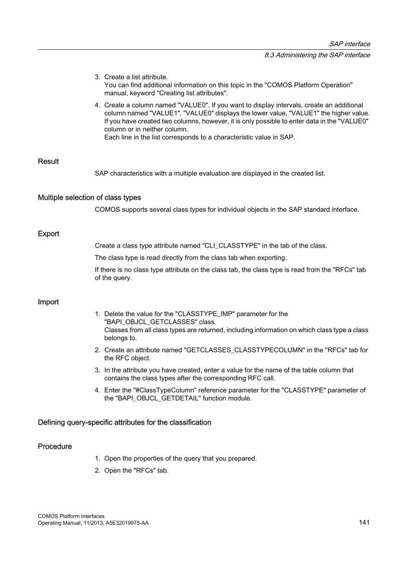
3. Create a list attribute.You can find additional information on this topic in the "COMOS Platform Operation" manual, keyword "Creating list attributes".
4. Create a column named "VALUE0". If you want to display intervals, create an additional column named "VALUE1". "VALUE0" displays the lower value, "VALUE1" the higher value.If you have created two columns, however, it is only possible to enter data in the "VALUE0" column or in neither column.Each line in the list corresponds to a characteristic value in SAP.
ResultSAP characteristics with a multiple evaluation are displayed in the created list.
Multiple selection of class typesCOMOS supports several class types for individual objects in the SAP standard interface.
ExportCreate a class type attribute named "CLI_CLASSTYPE" in the tab of the class.
The class type is read directly from the class tab when exporting.
If there is no class type attribute on the class tab, the class type is read from the "RFCs" tab of the query.
Import1. Delete the value for the "CLASSTYPE_IMP" parameter for the
"BAPI_OBJCL_GETCLASSES" class.Classes from all class types are returned, including information on which class type a class belongs to.
2. Create an attribute named "GETCLASSES_CLASSTYPECOLUMN" in the "RFCs" tab for the RFC object.
3. In the attribute you have created, enter a value for the name of the table column that contains the class types after the corresponding RFC call.
4. Enter the "#ClassTypeColumn" reference parameter for the "CLASSTYPE" parameter of the "BAPI_OBJCL_GETDETAIL" function module.
Defining query-specific attributes for the classification
Procedure1. Open the properties of the query that you prepared.
2. Open the "RFCs" tab.
SAP interface8.3 Administering the SAP interface
COMOS Platform InterfacesOperating Manual, 11/2013, A5E32019975-AA 141

3. Select from the "Object table" list the name of the object table that you require for the classification.
4. Select from the "Class type" list the type of class that you require for the classification.On export, the class type is only evaluated if this attribute is not available on the class tab of the interface object. When an import is performed, the class type is only evaluated if the "GETCLASSES_CLASSTYPECOLUM" attribute is not defined in the "RFCs" tab of the RFC object.
8.3.5.12 Import and export settings for COMOS attributesEvery COMOS attribute has an XML string. You use these to assign the attributes with import and export properties that you use for data communication with SAP.<Comos><System><SAP><FlowDirection>IN/OUT</FlowDirection><Unit>M0.25</Unit><Type>Character/Date/Time/Numeric/Currency</Type></SAP></System></Comos>
<FlowDirection>You specify the direction of data communication between COMOS and SAP using the <FlowDirection> element. By default the element is blank and the data flows in both directions.
● If you fill the element with the "IN" value, the data only flows from SAP to COMOS.
● If you fill the element with the "OUT" value, the data only flows from COMOS to SAP.
<Unit>In COMOS, you can assign units to numeric attributes. For example, you can assign the unit grams, kilogram, ton, etc., to the Weight attribute.
In order to assign a unit to an attribute, select a unit group and a unit in the attribute properties.
When working with the attribute you can change the unit shown within the scope of the group and, for example, switch from kilograms to grams.
The <Unit> element exchanges the attribute value along with your desired unit with SAP and converts it. For this, you fill the element with the name of the desired unit.
The unit must be a component of the specified unit group.
<Type>To format attribute values from COMOS for data communication with SAP in a particular way, you use the <Type> element.
SAP interface8.3 Administering the SAP interface
COMOS Platform Interfaces142 Operating Manual, 11/2013, A5E32019975-AA

Example: The attribute for the date in COMOS contains the date as well as the time of day. In SAP, the date and time of day are managed separately.
With the help of the <Type> element, you specify the format for the attribute values to be exchanged with SAP.
OverviewYou can set the following values in the <Type> element:
Value DescriptionCharacter The attribute value from COMOS is treated as a character string.Numeric The attribute value from COMOS is interpreted as a number.Currency The attribute value from COMOS is interpreted as a number and as a currency at
the same time.Date The attribute value from COMOS is interpreted as an SAP date in the format
YYYYMMDD.Time The attribute value from COMOS is interpreted as an SAP time in the format
HHMMSS.
If you do not use the <Type> element, standard values are selected:
● For attributes of the "Edit field" type
– (Number): Numeric– (Text or alphanumeric): Character
● For attributes of the Date type: Date
8.3.6 XML schema for the data communicationThe following describes the individual elements of the XML schema.
<ComosSAPInterface>The XML base element must always have the name ComosSAPInterface.
<Login>The <Login> element is located directly below the base element and contains five sub-elements:
Element Description<Application> Contains the IP address of the SAP Application Server.<Client> Contains the SAP Client ID.<Language> Contains the login language code.<SystemNumber> Contains the SAP system number.<User> Contains the SAP user name.
SAP interface8.3 Administering the SAP interface
COMOS Platform InterfacesOperating Manual, 11/2013, A5E32019975-AA 143

<Context>The Context element contains general information on data communication with SAP. It comprises the following sub-elements and attributes:
Element Description<Timestamp> Contains the date and time of the data communication with SAP.<Project> Contains the name of the project in which the data communication took place.<WorkingLayer> This element and the associated attributes are only created if the data communication
took place in a COMOS working layer. The SystemFullName attribute contains the SystemFullName of the working layer in which the exchange took place. The ID attribute contains the identification number of the working layer.
<StartObject> Contains the reference object for data communication with SAP. This is usually the XML connector.
<BOGroup>The <BOGroup> element is used to group several several business objects (BOs) of the same type that will be processed with the same SAP function modules.
The XML schema must include an element with the name BOGroup for each different BOType that is to be exchanged.
Attribute DescriptionType Contains the business object type.Assembly Contains the name of the assembly that contains the class for the processing of the
BOGroup element.Class Contains the complete name of the class for the processing of the BOGroup element.GroupID Contains a value that serves to distinguish between several BOGroup nodes of the same
type within an XML file.
<RFCS>The BOGroup element contains the RFCS sub-element. The content of the RFCS element is based in the "RFCs" tab of the RFC object.
The RFCS element contains a <RFC> sub-element for each RFC that is used during the data communication with SAP:
Attribute/Element DescriptionName attribute Contains the name of the RFC.Type attribute Contains the type of the RFC.RFC element Contains additional sub-elements: <Import><Export><Table>.
Import parameters are grouped together below the <Import> element.Export parameters and table parameters are grouped together below the <Export> and <Table> elements respectively.Within these sub-elements, there are additional Parameter sub-elements that contain the parameters the SAP interface needs for the data communication.
SAP interface8.3 Administering the SAP interface
COMOS Platform Interfaces144 Operating Manual, 11/2013, A5E32019975-AA

<BOGroupParam>The BOGroupParam element contains the RFC parameters required for the import. The values of these parameters are located in the "RFCs" tab of the query.
Element Description<Fields> For each field parameter, the Fields element contains a Field element with a
Attribut Name that contains the name of the field, and a Attribut Value that contains the value of the field.
<Structures> The Structures element contains sub-elements with the name Structure. The Structure sub-element contains a sub-element with the Namen Field for each element in the structure.
<Tables> The Tables element contains sub-elements with the name Table. The Table sub-element contains a Row element for each row in the table and a Field element for each field in the row.
<BO>The BOGroup element contains a BO sub-element for each Business Object that is imported or exported via the SAP interface. The BO sub-element contains the attributes SAPID and Status.
● The SAPID attribute contains the identification number of the business object that was imported or exported via the SAP interface.
● The Status attribute is set after the import or export.
SAP interface8.3 Administering the SAP interface
COMOS Platform InterfacesOperating Manual, 11/2013, A5E32019975-AA 145

● <Parameters>The Parameters sub-element contains a description of the parameters that are required for the RFC calls pertaining to each business object. It contains the following three sub-elements:
Element Description<Fields> For each field parameter, there is a Field
element in the Fields element with a Attribut Name that contains the name of the field, and a Attribut Value that contains the value of the field.
<Structures> The Structures element contains sub-elements with the name Structure. The Structure sub-element contains a sub-element with the Namen Field for each element in the structure.
<Tables> The Tables element contains sub-elements with the name Table. The Table sub-element contains a Row element for each row in the table and a Field element for each field in the row.
● <Return>The Return sub-element is created after the exchange of data and contains information on the progress of the export or import operation.An RFC sub-element is created for each RFC called for the corresponding business object. The element contains the following attributes:
Attribute DescriptionName Contains the name of the RFC.Type Contains the type of the RFC.DateTime Contains information on the time of the RFC call.Status Contains information on the success or failure of
the RFC call. The data that is displayed within the attribute depends on the details that you entered in the "RFCs" tab of the RFC object.
8.3.7 Deleting XML files after data communication
RequirementThe "Show file" option is deactivated during data communication. If this option is activated, the XML file with the data returned by SAP is not deleted, as it is needed for display purposes.
Procedure1. Open the base project.
2. Select the "Documents" tab in the Navigator.
3. Select an SAP adapter.
4. Open the properties of the adapter.
SAP interface8.3 Administering the SAP interface
COMOS Platform Interfaces146 Operating Manual, 11/2013, A5E32019975-AA

5. Select the "Attributes > SAP" tab.
6. Activate the "Delete XML file after exchange" option.
ResultThe XML file generated is deleted automatically after every data exchange.
8.3.8 Configuring the SAP "Maintenance" module
8.3.8.1 Introduction
Data exchangeCOMOS supports data communication with the SAP "Maintenance" module.
You can implement data communication in other areas of the "Maintenance" module on the basis of the "Custom" user-defined BOType.
See alsoFunctional locations (Page 147)
Equipment (Page 150)
8.3.8.2 Functional locations
Workflow for the import and export
Export sequence
Action RFC type Example1. A check is made for each functional location to determine whether a
functional location has already been created in SAP.CHECKEXISTENCE
BAPI_FUNCLOC_GETDETAIL
2. If the functional location exists, an RFC for updating the functional location is called.
UPDATE BAPI_FUNCLOC_CHANGE
3. If a functional location does not yet exist, a new functional location is created.
CREATE BAPI_FUNCLOC_CREATE
4. The classification of the functional location is updated. CHANGECLASS BAPI_OBJCL_CHANGE
SAP interface8.3 Administering the SAP interface
COMOS Platform InterfacesOperating Manual, 11/2013, A5E32019975-AA 147
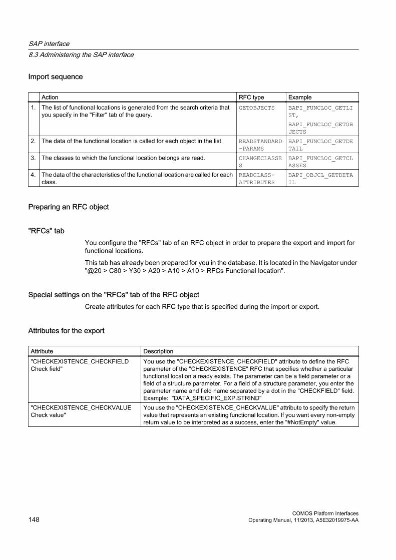
Import sequence
Action RFC type Example1. The list of functional locations is generated from the search criteria that
you specify in the "Filter" tab of the query.GETOBJECTS BAPI_FUNCLOC_GETLI
ST,BAPI_FUNCLOC_GETOBJECTS
2. The data of the functional location is called for each object in the list. READSTANDARD-PARAMS
BAPI_FUNCLOC_GETDETAIL
3. The classes to which the functional location belongs are read. CHANGECLASSES
BAPI_FUNCLOC_GETCLASSES
4. The data of the characteristics of the functional location are called for each class.
READCLASS-ATTRIBUTES
BAPI_OBJCL_GETDETAIL
Preparing an RFC object
"RFCs" tabYou configure the "RFCs" tab of an RFC object in order to prepare the export and import for functional locations.
This tab has already been prepared for you in the database. It is located in the Navigator under "@20 > C80 > Y30 > A20 > A10 > A10 > RFCs Functional location".
Special settings on the "RFCs" tab of the RFC objectCreate attributes for each RFC type that is specified during the import or export.
Attributes for the export
Attribute Description"CHECKEXISTENCE_CHECKFIELD Check field"
You use the "CHECKEXISTENCE_CHECKFIELD" attribute to define the RFC parameter of the "CHECKEXISTENCE" RFC that specifies whether a particular functional location already exists. The parameter can be a field parameter or a field of a structure parameter. For a field of a structure parameter, you enter the parameter name and field name separated by a dot in the "CHECKFIELD" field. Example: "DATA_SPECIFIC_EXP.STRIND"
"CHECKEXISTENCE_CHECKVALUE Check value"
You use the "CHECKEXISTENCE_CHECKVALUE" attribute to specify the return value that represents an existing functional location. If you want every non-empty return value to be interpreted as a success, enter the "#NotEmpty" value.
SAP interface8.3 Administering the SAP interface
COMOS Platform Interfaces148 Operating Manual, 11/2013, A5E32019975-AA

Attributes for the import
Attribute Description"GETOBJECTS_OBJECTSIDCOLUMN Objects ID column"
The "GETOBJECTS" RFC returns a list of functional locations in table format. In the "GETOBJECTS_OBJECTSIDCOLUMN" attribute, you enter the name of the table column that contains the IDs of the objects. "ALLOCLIST.OBJECT" example. "ALLOCLIST" stands for the table name and "OBJECT" for the column name. The individual IDs of the functional locations can be used in the following RFCs using the "#ObjectIdColumn" entry in the "Ref. parameter" column. This means that the return parameter of an RFC can be used as the input parameter in another RFC. Example: "GETOBJECTS_OBJECTSIDCOLUMN" has the value "ALLOCLIST.OBJECT".For each object ID which the RFC GetObjects puts out, the RFC ReadStandardParams is called once. By entering the "#ObjectIdColumn" label in the Ref. Parameter column of the "FUNCTLOCATION" parameter, the current object ID for the "FUNCTLOCATION" parameter is used in each case when the RFC is called.
"READSTANDARDPARAMS_OWNERID Read standard parameters RFC"
You use the "READSTANDARDPARAMS_OWNERID" attribute to specify that the functional locations will be created in the correct order in COMOS during the import operation. In the attribute, you enter the RFC parameter that contains the higher-level functional location. The parameter can be a field parameter or a structure parameter. Example: "DATA_SPECIFIC.SUPFLOC." in the "OWNERID" field
"GETCLASSES_CLASSIDCOLUMN Class ID column"
The "GETCLASSES" RFC type provides a table with all classes to which a functional location belongs. You use the "GETCLASSES_CLASSIDCOLUMN" attribute to specify which table column contains the class names. Example: "ALLOCLIST.CLASSNUM." in the "CLASSIDCOLUMN" fieldYou can use the returned class names as input parameters in subsequent function modules later in the import procedure using the "#ClassIdColumn" entry. For this, you enter "#ClassIdColumn" in the "Ref. Parameter" column of the parameter.
Configuring an XML connectorYou can find a query named "A10 Functional location import via classification" in the base objects of the base project below the "@20 > A70 > Y30 > M03 > A20 > A10 > A10" "node.
This query has already been configured for the import and export of functional locations. You can also create a new query and configure it. See also chapter Creating a query for the XML connector (Page 134).
Procedure1. Open the properties of the query.
2. Select the "Attributes > RFCs" tab.
3. Configure the attributes of the "RFCs" tab.Connect the query with the corresponding XML connector.
4. Select the "XML > Configure XML connector" command in the context menu of the XML connector.
SAP interface8.3 Administering the SAP interface
COMOS Platform InterfacesOperating Manual, 11/2013, A5E32019975-AA 149

5. Select the "Assignment" tab.
6. Enter the following value in the "XML collection" field:"/BOGroup[@Type ="FunctionalLocation"]/BO"
Attributes of the "RFCs" tab
Control element Setting"Status" list Select the status of the class from the list."Class type" list Select the "Functional location class" setting from the list."Object table" list Select the "Functional location table" setting from the list."RFC object" field Set the "@20 > C80 > Y30 > A20 > A10 > A10 RFC object for functional
locations" RFC object as pointer in this field."Class" field Enter the following value in the field:
"Comos.Sap.Xml.FunctLocation.""Assembly" field Enter the following value in the field:
"Comos.Sap.Xml."
See alsoCreating an XML connector (Page 137)
8.3.8.3 Equipment
Workflow for the import and export
Export sequence
Action RFC type Example1. Each equipment item is checked to see whether it is created in SAP. CHECKEXISTENC
EBAPI_EQUI_GETDETAIL
2. If the equipment exists, an RFC for updating the equipment is called. UPDATE BAPI_EQUI_CHANGE3. If the equipment does not yet exist, it is created. CREATE BAPI_EQUI_CREATE4. The classification of the equipment is updated. CHANGECLASS BAPI_OBJCL_CHANGE
SAP interface8.3 Administering the SAP interface
COMOS Platform Interfaces150 Operating Manual, 11/2013, A5E32019975-AA

Import sequence
Action RFC type Example RFC1. The list of equipment is generated from the search criteria that you
specify in the "Filter" tab of the query.GETOBJECTS BAPI_EQUI_GETLIST,
BAPI_OBJCI_GETOBJECTS
2. For each item of equipment in the list, the data of the equipment is read. READSTANDARD-PARAMS
BAPI_EQUI_GETDETAIL
3. The classes to which the equipment belongs are read. GETCLASSES BAPI_OBJCL_GETCLASSES
4. The data of the characteristics of the equipment are read for each class. READCLASS-ATTRIBUTES
BAPI_OBJCL_GETDETAIL
Preparing an RFC object
"RFCs" tabIn order to prepare the export or import of the equipment, you must first create the "RFCs" tab at an RFC object. See also chapters Create RFC objects (Page 130) and Type mapping of the RFC object (Page 162).
This tab has already been prepared for you in the database. It is located in the Navigator under "@20 > C80 > Y30 > A20 > A20 > A10 > RFCs Equipment".
Configuring an XML connectorPrepare the XML connectors for the equipment.
You can find the "A20 Equipment with import via classification" query under the "@20 > A70 > Y30 > M03 > A20 > A10 > A20 Query template for documents" node in the base objects.
Procedure1. Open the properties of the query.
2. Select the "Attributes > RFCs" tab.
3. Configure the attributes.Connect the query with the corresponding XML connector.
4. Select the "XML > Configure XML connector" command in the context menu of the XML connector.
5. Select the "Assignment" tab.
6. Enter the following value in the "XML collection" field:"/BOGroup[@Type ="Equipment"]/BO".
SAP interface8.3 Administering the SAP interface
COMOS Platform InterfacesOperating Manual, 11/2013, A5E32019975-AA 151
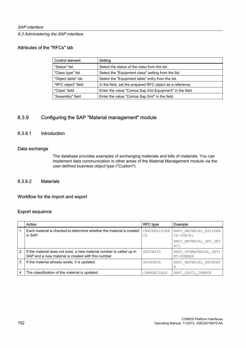
Attributes of the "RFCs" tab
Control element Setting"Status" list Select the status of the class from the list."Class type" list Select the "Equipment class" setting from the list."Object table" list Select the "Equipment table" entry from the list."RFC object" field In the field, set the prepared RFC object as a reference. "Class" field Enter the value "Comos.Sap.Xml.Equipment" in the field."Assembly" field Enter the value "Comos.Sap.Xml" in the field.
8.3.9 Configuring the SAP "Material management" module
8.3.9.1 Introduction
Data exchangeThe database provides examples of exchanging materials and bills of materials. You can implement data communication in other areas of the Material Management module via the user-defined business object type ("Custom").
8.3.9.2 Materials
Workflow for the import and export
Export sequence
Action RFC type Example1. Each material is checked to determine whether the material is created
in SAP.CHECKEXISTENCE
BAPI_MATERIAL_EXISTENCE-CHECK;BAPI_MATERIAL_GET_DETAIL
2. If the material does not exist, a new material number is called up in SAP and a new material is created with this number.
GETSAPID BAPI_STDMATERIAL_GETINT-NUMBER
3. If the material already exists, it is updated. SAVEDATA BAPI_MATERIAL_SAVEDATA
4. The classification of the material is updated. CHANGECLASS BAPI_OBJCL_CHANGE
SAP interface8.3 Administering the SAP interface
COMOS Platform Interfaces152 Operating Manual, 11/2013, A5E32019975-AA

Import sequence
Action RFC type Example RFC1. The list of functional locations is generated from the search criteria that
you specify in the "Filter" tab of the query.GETOBJECTS BAPI_MATERIAL_GETLIST
;BAPI_OBJCL_GETOBJECTS
2. The data of the material is called for each object in the list. READSTANDARD-PARAMS
BAPI_MATERIAL_GET_DETAIL
3. All classes to which the material belongs are read. GETCLASSES BAPI_OBJCL_GETCLASSES4. Then the characteristics data of the material is called for each class. READCLASS-
ATTRIBUTESBAPI_OBJCL_GETDETAIL
Preparing RFC objects
"RFCs" tabIn order to prepare the export or import for materials, you first create the "RFCs" tab of the RFC object.
A tab has already been prepared in the database. You can find it in the Navigator in the "Base objects" tab under "@20 > C80 > Y30 > A20 > A40 > A10 > RFCs Materials".
Export and import attributesCreate attributes for each RFC type that is specified for the import and export.
Attributes for the export
Attribute Description"GETSAPID_OBJECTSIDCOLUMN SAP ID Column"
When a new material is to be created in SAP, then first of all an RFC to query a new material number is called. The "GETSAPID_OBJECTSIDCOLUMN" attribute must contain the name of the parameter that contains the returned material number. The parameter can be a field parameter, the field of a structure or the column of a table. If the parameter is the column of a table, the first column entry is used. If the parameter involves a structure field or a table column, you specify the parameter name and the field name separated by a dot. Example: "MATERIAL_NUMBER.MATERIAL." in the "SAP ID Column" field
"SAVEDATA_ADDPARAM SAP ID Parameter"
In the "SAP ID parameter" attribute, enter the name of the parameter that contains the material number of the material to be saved, e.g. "HEADDATA.MATERIAL".
SAP interface8.3 Administering the SAP interface
COMOS Platform InterfacesOperating Manual, 11/2013, A5E32019975-AA 153
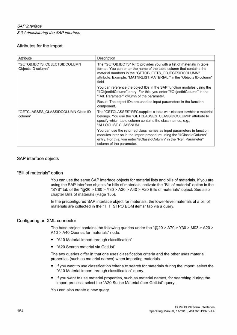
Attributes for the import
Attribute Description"GETOBJECTS_OBJECTSIDCOLUMN Objects ID column"
The "GETOBJECTS" RFC provides you with a list of materials in table format. You can enter the name of the table column that contains the material numbers in the "GETOBJECTS_OBJECTSIDCOLUMN" attribute. Example: "MATNRLIST.MATERIAL." in the "Objects ID column" fieldYou can reference the object IDs in the SAP function modules using the "#ObjectIdColumn" entry. For this, you enter "#ObjectIdColumn" in the "Ref. Parameter" column of the parameter.Result: The object IDs are used as input parameters in the function component.
"GETCLASSES_CLASSIDCOLUMN Class ID column"
The "GETCLASSES" RFC supplies a table with classes to which a material belongs. You use the "GETCLASSES_CLASSIDCOLUMN" attribute to specify which table column contains the class names, e.g., "ALLOCLIST.CLASSNUM".You can use the returned class names as input parameters in function modules later on in the import procedure using the "#ClassIdColumn" entry. For this, you enter "#ClassIdColumn" in the "Ref. Parameter" column of the parameter.
SAP interface objects
"Bill of materials" optionYou can use the same SAP interface objects for material lists and bills of materials. If you are using the SAP interface objects for bills of materials, activate the "Bill of material" option in the "SYS" tab of the "@20 > C80 > Y30 > A30 > A40 > A20 Bills of materials" object. See also chapter Bills of materials (Page 155).
In the preconfigured SAP interface object for materials, the lower-level materials of a bill of materials are collected in the "T_T_STPO BOM items" tab via a query.
Configuring an XML connectorThe base project contains the following queries under the "@20 > A70 > Y30 > M03 > A20 > A10 > A40 Queries for materials" node:
● "A10 Material import through classification"
● "A20 Search material via GetList"
The two queries differ in that one uses classification criteria and the other uses material properties (such as material names) when importing materials.
● If you want to use classification criteria to search for materials during the import, select the "A10 Material import through classification" query.
● If you want to use material properties, such as material names, for searching during the import process, select the "A20 Suche Material über GetList" query.
You can also create a new query.
SAP interface8.3 Administering the SAP interface
COMOS Platform Interfaces154 Operating Manual, 11/2013, A5E32019975-AA

Procedure1. Open the properties of the query.
2. Select the "Attributes > Settings" tab.
3. Configure the attributes.Once you have configured the attributes, connect the query with the corresponding XML connector.
4. Select the "XML > Configure XML connector" command in the context menu of the XML connector.
5. Select the "Assignment" tab.
6. Enter the following path in the "XML collection" field:"/BOGroup[@Type ="Material"]/BO"
Attributes of the "Attributes > Settings" tab
Control element Setting "Status" list Select the status of the class from the list. "Class type" list Select the "Material class" entry from the list. "Object table" list Select the "Material table" setting from the list. "RFC object" field In the field, set the prepared RFC object as a reference. "Class" field Enter the value "Comos.Sap.Xml.Material" in the field. "Assembly" field Enter the value "Comos.Sap.Xml" in the field.
8.3.9.3 Bills of materials
Workflow for the export
SequenceThe database contains an SAP example for exporting bills of materials.
Only export operations are supported for Bill of Materials.
Action RFC type Example1. A check is made to determine whether SAP contains the material the
bill of materials of which is to be changed.CHECKEXISTENCE
BAPI_MATERIAL_EXISTENCE-CHECK;BAPI_MATERIAL_GET_DETAIL
2. The bill of materials is updated only if the material exists. SAVEBOM CSAP_MAT_BOM_MAINTAIN
SAP interface8.3 Administering the SAP interface
COMOS Platform InterfacesOperating Manual, 11/2013, A5E32019975-AA 155

Preparing an RFC object
"RFCs" tabYou first have to create the "RFCs" tab of the RFC object to prepare the export operation for bills of materials.
A tab has already been prepared for you in the database. You can find it in the Navigator in the "Base objects" tab under "@40 > A20 > Y30 > M03 > A10 > RFCs > A01 > B01 > C02 BOM".
SAP interface objects
"Bill of materials" optionAfter having created the "RFCs" tab, you create the SAP interface objects. You can use the same SAP interface objects for bills of materials as for materials.
For bills of materials, activate the "Bill of materials" option at the "@20 > C80 > Y30 > A30 > A40 Materials" object in the "Attributes > SYS" tab.
Configuring an XML connectorYou can find the "A40 > A30 Export Bill of Materials" query under the "@20 > A70 > Y30 > M03 > A20 > A10 XML connector templates" node in the base objects of the base project.
Procedure1. Open the properties of the query.
2. Select the "Attributes > Settings for SAP queries" tab.
3. Configure the attributes.Connect the query with the corresponding XML connector.
4. Select the "XML > Configure XML connector" command in the context menu of the XML connector.You also have the option of creating a new XML connector.
5. Select the "Assignment" tab in the configuration tool.
6. Enter the following path in the "XML collection" field:"/BOGroup[@Type ="BOM"]/BO"
Attributes of the "Attributes > Settings for SAP queries" tab
Control element Setting "Status" list Select the status of the class from the list. "Class type" list Select the "Material class" entry from the list."Object table" list Select the "Material table" entry from the list.
SAP interface8.3 Administering the SAP interface
COMOS Platform Interfaces156 Operating Manual, 11/2013, A5E32019975-AA

Control element Setting "RFC object" field In the "RFC object" field, set the prepared object as a reference. "Class" field Enter the value "Comos.Sap.Xml.Bom" in the field. "Assembly" field Enter the value "Comos.Sap.Xml" in the field.
8.3.10 Configuring the SAP "Documents" module
8.3.10.1 Introduction
ExportYou can use the COMOS SAP Interface to exchange documents between COMOS and SAP. Only exporting is supported.
8.3.10.2 Workflow for exporting documents
Sequence
Action RFC type Example1. Each document is checked if the document has already been created
in SAP.CHECKEXISTENCE
BAPI_DOCUMENT_EXISTENCE-CHECK
2. If the document does not exist, a new document is created in SAP. CREATE BAPI_DOCUMENT_CREATE2
3. If the document already exists, a new version of the document is created depending on the setting.
CREATENEW-VERSION
BAPI_DOCUMENT_CREATENEW-VRS2
4. The document is updated. UPDATE BAPI_DOCUMENT_CHANGE2
5. The classification of the document is updated. CHANGECLASS
BAPI_OBJCL_CHANGE
8.3.10.3 Preparing an RFC object
"RFCs" tabIn order to prepare the export of documents, create the "RFCs" tab of the RFC object for a COMOS object.
This tab has already been prepared for you in the database. You can find it in the Navigator in the "Base objects" tab under "@20 > C80 > Y30 > A20 > A30 > A10 > RFCs Document".
SAP interface8.3 Administering the SAP interface
COMOS Platform InterfacesOperating Manual, 11/2013, A5E32019975-AA 157

8.3.10.4 Configuring an XML connectorYou can find the "A30 > A10 Export documents" object query under the "@20 > A70 > Y30 > M03 > A20 > A10 XML connector template" node in the base objects of the base project.
Procedure1. Open the properties of the query.
2. Select the "Attributes > Settings for SAP queries" tab.
3. Configure the attributes.Connect the query with the XML connector. You also have the option of creating a new XML connector.
4. Select the "XML > Configure XML connector" command in the context menu of the XML connector.
5. Click the "Assignment" tab.
6. Enter the following path in the "XML connection" field:"/BOGroup[@Type ="Document"]/BO"
Attributes of the "Attributes > Settings for SAP queries" tab
Control element Setting "Status" list Select the status of the class from the list. "Class type" list Select the "Document class" setting from the list. "Object table" list Select the "Document table" setting from the list. "RFC object" field In the "RFC object" field, set the prepared object as a reference."Class" field Enter the value "Comos.Sap.Xml.Document" in the field. "Assembly" field Enter the value "Comos.Sap.Xml" in the field.
8.3.10.5 Special settings on the "RFCs" tab of the RFC objectCreate attributes for each RFC type that is specified in the export workflow.
SAP interface8.3 Administering the SAP interface
COMOS Platform Interfaces158 Operating Manual, 11/2013, A5E32019975-AA

Attributes for the export
Attribute Description"CHECKEXISTENCE_CHECKFIELD Check field"
You use the "CHECKEXISTENCE_CHECKFIELD" attribute to define the parameter of the "CHECKEXISTENCE" RFC that specifies whether a particular document already exists. The parameter can involve a field parameter or an individual field of a structure parameter. If a structure parameter is involved, enter the parameter name and field name separated by a dot.
"CHECKEXISTENCE_CHECKVALUE Check value"
You use the "CHECKEXISTENCE_CHECKVALUE" attribute to specify the return value that represents an existing document. If you want every non-empty return value to be interpreted as a success, enter the "#NotEmpty" value in the "Check value" field.
8.3.10.6 SAP interface objects
"Create revision on export" optionSAP interface objects for documents have the "Create revision on export" option in the "SYS" tab in the "@20 > C80 > Y30 > A30 > A30 Documents" node. Activate this option in order to create a new version from an document that exists in SAP.
8.3.11 Importing the device catalog
8.3.11.1 Introduction
Manufacturer device selectionThe manufacturer device selection enables you to assign a manufacturer device to a request object. During the assignment, the relevant product data of the selected material is directly copied to the request object.
Some of the manufacturer devices are provided in the form of COMOS base objects. To keep the number of base objects low, you can also connect to external manufacturer device catalogs from SAP. See also chapter Defining an SAP catalog object (Page 159).
8.3.11.2 Defining an SAP catalog objectDefine an SAP catalog object for each manufacturer device catalog you want to access from COMOS.
Procedure1. In the base data, open the "@99 > A30 > M00 > A10 > A10 SAP catalog" object.
2. Select the "New > New base object" command in the context menu.
SAP interface8.3 Administering the SAP interface
COMOS Platform InterfacesOperating Manual, 11/2013, A5E32019975-AA 159

3. Select the "Attributes > SAP" tab.
4. Enter the login data for the connection to the SAP system.
5. Select the "Attributes > Class" tab.
6. Enter "Comos.Sap.Xml.SapCatalogConnection" in the "Used class" field. This component is used for the following tasks:
– Creating a connection with the manufacturer device catalog.
– Downloading materials
– Performing a conversion from the XML format of the SAP interface to the XML format of the manufacturer device selection.
The "Program path" field remains blank.
7. Select the "Attributes > Standard filter" tab.
8. Specify the selection criteria of the devices that are to be downloaded. This involves filter parameters, such as those already offered by the SAP interface.
9. Select the "Attributes > General" tab.
10.Drag&drop an SAP interface base object to the "Reference SAP interface object" field.From this object, the necessary information for mapping an XML file in the format of the SAP interface is converted into the COMOS internal format of the manufacturer device selection.
8.3.11.3 Defining a queryFor an SAP catalog object, there is a query in each case with a special extension for the manufacturer device selection from SAP. It shows the manufacturer devices imported from SAP and their assignment to COMOS attributes. The SAP interface base object set at the catalog is used for the assignment. The COMOS attributes displayed in the query are the attributes of the SAP interface base object that have the link type "By owner".
Procedure1. Open the "Elements" tab in the properties of the SAP catalog object.
2. Navigate to the "@20 > A70 > Y10 > M03 > A10 Query: SAP manufacturer device catalog" object in the base data.
3. Use drag&drop to move the query onto the "Elements" tab of the catalog object.
ResultThe query is created under the manufacturer device catalog.
SAP interface8.3 Administering the SAP interface
COMOS Platform Interfaces160 Operating Manual, 11/2013, A5E32019975-AA

8.3.11.4 Commands in the context menu of the column headers
Overview
Command Description"Import data from SAP" This entry opens a connection to SAP with the connection data defined for the SAP
catalog object. The RFCs also defined using the catalog object are called using the standard SAP interface. The called XML mapping is then reevaluated.
"Refresh mapping" This entry refreshes the assignment of the data retrieved from SAP in XML format to the assignment of XML data for the manufacturer device selection and evaluates it again. No new data is called from SAP. Changes to the SAP interface base object are taken into consideration.
"Generate XML" Generates an XML file in the format for the manufacturer device selection from all imported manufacturer devices.
"Generate XML for selection" Generates an XML file in the format for the manufacturer device selection from the manufacturer devices selected in the query.
"Restore last selection" Marks the manufacturer devices that were selected during the last generation of the manufacturer device XML file in the query.
8.3.11.5 Importing devices
Procedure1. Open the "A10 Query: SAP manufacturer device catalog" query you have created under
the manufacturer device catalog. See also chapter Defining a query (Page 160).
2. Open the context menu of a column in the query.
3. Select the "Import data from SAP" command.
4. Enter your user data.An XML file containing all manufacturer devices from SAP is generated in the interface format.
5. Select the "Generate XML" command in the context menu.An XML file is generated in the format for the manufacturer device selection from all imported manufacturer devices.If you only want to generate an XML file from the manufacturer devices selected in the query, select the "Generate XML for selection" command.
6. Confirm your entries.
ResultThe manufacturer devices from SAP are saved in the SAP catalog object. You can use the catalog via the standard user interface for device selection. You can find additional information on this topic in the "EI&C Administration" manual, keyword "Manufacturer device selection".
SAP interface8.3 Administering the SAP interface
COMOS Platform InterfacesOperating Manual, 11/2013, A5E32019975-AA 161

8.3.11.6 Assignment of XML dataTo convert XML data from the standard SAP interface format into the format of the manufacturer device selection, the information required for the assignment is read from an SAP interface base object. This SAP Interface base object must be set at the corresponding SAP object catalog.
Assignment sequence1. A search is performed for SAP-related attributes at the SAP interface base object. The base
objects have a prefix such as "F_ " in the "General" tab or in a tab with the "S_", "T_", or "CL_" prefix.
2. These attributes are checked for a "By owner" type link. If such a link is present, it is used for assigning the corresponding value in the XML document of the standard SAP interface to the value in the XML document of the manufacturer device selection. The assignment follows the behavior of the standard SAP interface.
3. If an attribute has settings for the flow direction, exchange type, or unit, these are also taken into consideration.
8.3.12 RFCs
8.3.12.1 "RFCs" tab of the RFC object
ParameterYou enter the selected RFCs as well as the associated parameters in the "RFCs" tab.
Catalog attributesYou can also create the "RFCs" tab with the help of catalog attributes. Catalog attributes are templates that speed up the creation of attributes and tabs. You can find the catalog attributes for the COMOS SAP interface in the base objects under the "@40 > A20 > Y30 > M03 SAP tabs" node.
Example of a catalog attribute"@40 > A20 > Y30 > M03 > A10 > RFCs > A01 > B01 > C01 > D01 > E01 > F01 @Y Functional location"
8.3.12.2 Type mapping of the RFC objectDefine a type that matches the respective SAP Business Object for the entire "RFCs" tab:
SAP interface8.3 Administering the SAP interface
COMOS Platform Interfaces162 Operating Manual, 11/2013, A5E32019975-AA

TypesThe following gives you an overview of the various types:
Type AssignmentFunctionalLocation Functional locationEquipment EquipmentBOM Bill of materialsMaterial MaterialDocuments DocumentCustom User-defined
8.3.12.3 Attributes of the RFC objectThe value of the attributes consists of a prefix, e.g., CREATE, and a suffix. The prefix is dependent on the RFC type.
OverviewThe following gives you an overview of settings that you make for the attributes in the "RFCs" tab:
Description Name of the attribute Attribute type Function"RFC" <PRÄFIX> Edit field Here, you enter the name of the RFC that you
selected."Activate commit" <PRÄFIX>_HASCOMMIT Checkbox If this option is activated, a Commit to the SAP
database is called after the RFC call."Check result message"
<PRÄFIX>_CHECKRESULT_MSG Edit field If needed, you can specify an RFC parameter here that will be written as a message to the SAP interface object. This value is for information only and has no effect on the sequence of the import or export.
"Check result parameter"
<PRÄFIX>_CHECKRESULT_PAR
Edit field Here, you specify an RFC parameter that indicates whether the call of the function module was successful.
"Check result values"
<PRÄFIX>_CHECK_RESULT_VALS
List If the "Check result parameter" field is filled in, you enter the values that indicate the successful call of the RFC here.
"Create para" <PRÄFIX>_PARAMS List Here, you enter the names of the RFC parameters that are to be exchanged with the SAP interface, i.e., the mandatory parameters of the RFC at a minimum.● "Parameter":
Enter the name of the parameter here.● "Import/Export":
Here, you input whether the parameter is an import, export or table parameter.
● "Ref. parameter":The entries in this column are optional.
SAP interface8.3 Administering the SAP interface
COMOS Platform InterfacesOperating Manual, 11/2013, A5E32019975-AA 163

Ref. ParameterRFC parameters often have different names although they have the same structure. As a rule, it is superfluous to retain the attributes for such parameters on the SAP interface object doubled. Instead, you enter a reference parameter in this column that is used instead of the parameter specified in the "Parameter" column. Depending on whether the parameter involves a field, a structure, or a table, you use the "F_", "S_" or "T_" prefix.
Example 1The "DATA_GENERAL" import parameter of the "BAPI_FUNCLOC_CHANGE" RFC has the same structure as the "DATA_GENERAL_EXP" export parameter. In order to write the data of "DATA_GENERAL_EXP" to the corresponding COMOS attributes for "DATA_GENERAL" for the SAP interface object, enter "S_DATA_GENERAL" as the reference parameter.
Example 2Use the number of a functional location ("FUNCTLOCATION" field parameter) for the "OBJECTKEY" import parameter of the "BAPI_OBJCL_CHANGE" RFC. For this, you enter "F_FUNCTLOCATION" as the reference parameter.
Example 3For import fields, you can specify the field of a structure as the reference parameter. Use the "MATERIAL" field of the "HEADDATA" structure for the "MATERIAL" import field of the "BAPI_MATERIAL_GET_DETAIL" RFC. This is done by stating the structure and the field names separated by a dot as follows: "S_HEADDATA.MATERIAL".
Associated structure parametersIn some RFCs two associated structure parameters are used that have exactly the same number of fields with the same field names. While the first structure contains the actual values for the RFC, the fields of the second structure use an "X" to indicate whether or not the value of the first structure is actually to be used. You do not need to create any attributes in COMOS for the second structure. Instead, you enter the name of the second structure, prefixed by "#X_" in the "Ref. parameter" table column. An "X" is then automatically entered in the relevant field of the second structure for each field of the first structure, assuming that there is an existing attribute for this in COMOS.
ExampleThere is an analogous "DATA_GENERALX" import structure for the "DATA_GENERAL" import structure of the "BAPI_FUNCLOC_CHANGE" RFC. In order for the X entries to be set correctly, enter the "#X_DATA_GENERALX" value in the "Ref. parameter" table column.
RFC parametersDepending on the type of business objects to be exchanged with SAP, the COMOS SAP interface in part makes use of special RFC parameters that you specify in the "RFCs" tab. To
SAP interface8.3 Administering the SAP interface
COMOS Platform Interfaces164 Operating Manual, 11/2013, A5E32019975-AA

enable access to these parameters in subsequent RFCs, you need to a special label in the "Ref. parameter" table column. The individual labels always begin with a "#".
ExampleDuring the import of equipment the RFC is called first, that then returns a table with the equipment. A specific column of this table contains the unique numbers of the equipment items. Subsequently, further RFCs are called for each column entry and supply the required details for the relevant equipment items. These column entries are referenced with the "#ObjectIdColumn" label and can be passed on to other RFCs in this way.
The sequence of calls of the SAP function modules defined in the "RFCs" tab depends on the business object type which has been assigned to the tab.
8.4 User interface
8.4.1 "SAP login" tab
Buttons
Button Description"Log in" Use this button to log in to the selected SAP target system."Log out" Use this button to log out of the selected SAP target system."New" Use this button to open the "Properties" window where you can create a
new SAP target system. The new SAP target system is listed in the table."Properties" Use this button to open the "Properties" window for the selected SAP target
system. "Current user" Use this button to show and hide the SAP target systems that have been
created only for the currently logged-in user."All users" Use this button to show and hide the SAP target systems that have been
created for all users.
SAP interface8.4 User interface
COMOS Platform InterfacesOperating Manual, 11/2013, A5E32019975-AA 165

8.4.2 "Properties" window for the SAP target system
"General" control groupDepending on which option is selected, properties are either activated or deactivated in the "General" control group accordingly. You will be alerted to any missing entries.
Control element Description"saplogon.ini file" option When this option is activated, the connection to SAP is
established via the "saplogon.ini" file."Server" option When this option is activated, the connection to SAP is
established via an application server."Group" option When this option is activated, the connection to SAP is
established via load balancing."Client" field The name of the SAP client."System description" list The name of the SAP target system as it appears in the
"saplogon.ini" file."Application server" field The name or IP of the application server."System number" field The number of the SAP target system."Messager server" field The name or IP of the message server."Group" field Shows the group."System ID" field Shows the ID of the SAP target system."Router" field Optional SAP router string.
Secure Network CommunicationThe control elements of this control group correspond to those of SAP. Ensure that the settings in COMOS and SAP match.
Control element Description"Enable Secure Network Communication" option
When this option is enabled, it is possible to log in with the PKI card.
"SNC name" field Enter the name of the Secure Network Client here."Quality of protection" list Select the desired security level for the login here."Deactivate single sign-on" option This activates logging on with user name and password instead of with a PIN with
Secure Network Communication.
SAP interface8.4 User interface
COMOS Platform Interfaces166 Operating Manual, 11/2013, A5E32019975-AA

"Options" control group
Control element Description"Language" field Specifies the language for establishing the connection to
SAP."SAP GUI" list Specifies whether the SAP user interface will generally be
displayed and whether it will be hidden between individual RFC calls.
"Enable RFC trace" option When this option is activated, the RFC trace is enabled for this connection.
"Administrator" control groupTo edit this control group, you need administrator rights.
The user category specifies whether the entry in the connection list is valid for just the current user or for all users. Entries that are valid for the current user can only be viewed and edited by the specific user concerned. Entries that are valid for all users can be viewed by all users and used to establish a connection. However, they can only be edited by COMOS administrators.
8.4.3 "General > XML" tab
Control elements
Control element Meaning"Envelope" field When the XML connector converts the SAP interface objects into XML it
puts them in an envelope that identifies the name of the external XML element. Enter the following:<ComosSAPInterface> <Content/></ComosSAPInterface>
"Adapter type" list Select the "SAP" adapter type from the list.
8.4.4 "SAP" tab
"SAP login" control group
Control element Function"Login mode" list Select the desired login mode from this list."Client" field This field displays the description of the SAP client.
SAP interface8.4 User interface
COMOS Platform InterfacesOperating Manual, 11/2013, A5E32019975-AA 167

Control element Function"Language" field This field specifies the language for establishing
the connection to SAP."SAP GUI" list Use this list to specify whether the SAP user
interface will generally be displayed and whether it will be hidden between individual RFC calls.
"Enable RFC trace" option When this option is activated, the RFC trace is enabled for this connection.
"Set user and password" button When you click on the "Set user and password" button, the "SAP Login Data" window opens so that you can enter a user name and a password for the connection to the SAP Server.
"System description" list The name of the SAP target system as it appears in the "saplogon.ini" file
"Application server" field The name or IP of the application server"Router" field Optional SAP router string"System ID" field Shows the ID of the SAP target system"System number" field The number of the SAP target system"Group" field Shows the group"Message server" field The name or IP of the massager server
"Secure Network Communication" control groupThe control elements of this control group correspond to those of SAP. Ensure that the settings in COMOS and SAP match.
Control element Description"Enable Secure Network Communication" option
When this option is enabled, it is possible to log in with the PKI card.
"SNC name" field Enter the name of the Secure Network Client here."Quality of protection" list Select the desired security level for the login here."Deactivate single sign-on" option This activates logging on with user name and password instead of with a PIN
with Secure Network Communication.
"Options" control group
Option Description"Write back export parameters" When this option is activated, data is written back
to COMOS after an SAP export operation. If, for example, you export documents from COMOS to SAP that do not exist yet in SAP, SAP assigns a new document number when it creates the documents. If the option is activated, the document number is written back to COMOS.
"Delete classification characteristics on import" This option applies to classification characteristics that are defined as a list, for example tables or bills of materials.
SAP interface8.4 User interface
COMOS Platform Interfaces168 Operating Manual, 11/2013, A5E32019975-AA

Option Description"Delete XML file after data exchange" When this option is activated, the XML file is
deleted automatically once the data has been exchanged.
"Keep COMOS active during RFCs with GUI" When this option is activated, COMOS remains active throughout your SAP session.
SAP interface8.4 User interface
COMOS Platform InterfacesOperating Manual, 11/2013, A5E32019975-AA 169


Interface to Teamcenter 99.1 COMOS Teamcenter interface
9.1.1 Introduction
Data exchangeCOMOS offers an interface for connecting the Siemens PLM software Teamcenter 8.3 and Teamcenter 9.1. The interface supports data communication in both directions. You can start the exchange from COMOS.
The link with Teamcenter provides you with the following options:
● You can create plants in Teamcenter and synchronize them with COMOS.See also chapter Synchronizing a unit from Teamcenter (Page 174).
● You can synchronize your existing COMOS unit with Teamcenter.See also chapter Synchronizing a unit to Teamcenter (Page 175).
● You can edit a synchronized plant either in COMOS or in Teamcenter and then resynchronized.
● You can transfer COMOS documents to Teamcenter.See also chapter Publishing documents (Page 176).
9.1.2 Terms
Mapping objectA mapping object is an engineering object created on the basis of a base object. A Teamcenter resource or a Teamcenter type must be assigned to the base object for this. Mapping objects can be synchronized between Teamcenter and COMOS.
PDIProcess Data Interface
Pipe parts are transferred from COMOS to NX via PDI. To use the functions of PDI, you need to use Teamcenter version 9.1 and NX version 9.0.
PLMPLM (Product Lifecycle Management) is uniform management of product data throughout the entire product lifecycle.
COMOS Platform InterfacesOperating Manual, 11/2013, A5E32019975-AA 171

SynchronizationSynchronization is the equivalent of repeated importing or exporting of data. Synchronization includes all cases in which only a portion of the data is to be updated.
TeamcenterSiemens PLM software Teamcenter
The COMOS interface has been designed to interface with Teamcenter Version 8.3.
AssignmentThe resources and types familiar in Teamcenter are initially independent of COMOS base objects. To link the relevant objects, they must be assigned to one another.
The resource assignment also determines which base object is used to create an object from Teamcenter in COMOS.
In the opposite direction, instance mapping defines the translation of COMOS engineering objects into resources or types that can be understood by Teamcenter.
Attributes and units of measurement are translated in both directions using corresponding assignments.
9.1.3 Transferring data from Teamcenter to COMOS
9.1.3.1 Basic principles
Preparation of data communication by the user● If you want to start the transfer for the first time, you must prepare the data communication
in COMOS. See chapter Configuring COMOS (Page 190).
● If you have already performed a synchronization from Teamcenter or to Teamcenter, use the prepared settings.
● In the event of problems during data communication, check that the default settings have been made and contact your administrator if necessary.
9.1.3.2 Mapping a unit from Teamcenter
ObjectivePlant data is to be transferred from the Siemens PLM solution Teamcenter to COMOS for the first time.
Interface to Teamcenter9.1 COMOS Teamcenter interface
COMOS Platform Interfaces172 Operating Manual, 11/2013, A5E32019975-AA

Procedure1. Create a new plant below the project node in the "Units" tab in the Navigator.
2. To determine the plant type used in Teamcenter, open the "@20 > B60 > M06 > Y30 > A20 Teamcenter types" node in the "Base objects" tab in the Navigator.The types used in Teamcenter are listed.
3. Open the properties of the object matching the type of your plant in Teamcenter.
4. To navigate to the corresponding base object, click the "Navigate, properties" button in the "Attributes > CTI resource mapping" tab and select "Navigate > Object".This object is to be created on the engineering side.
5. Use drag&drop to move this object from the "Base objects" tab onto the plant in the "Units" tab.
9.1.3.3 Checking and making settings
RequirementThe created plant is classified. A Teamcenter integrator object is added.
Procedure1. To check the classification, select the created plant in the "Units" tab in the Navigator and
navigate to the base object.
2. Open the base object properties.
3. Open the "Classification" tab.
4. Check whether the "A490 Teamcenter object" entry is set in the "Functional classification" list.If it is not, inform your administrator.
5. Check whether the "Teamcenter integrator" object is present in the "Units" tab of the Navigator in the mapping of the unit:
– If this object is listed, the interface is ready for connection to Teamcenter.
– If it is not listed, add a Teamcenter integrator object:Open the "@20 > B60 > M06 > A10 > A10 Teamcenter integrator" node in the "Base objects" tab in the Navigator.Use drag&drop to move the Teamcenter integrator object onto the plant in the Units tab.
Interface to Teamcenter9.1 COMOS Teamcenter interface
COMOS Platform InterfacesOperating Manual, 11/2013, A5E32019975-AA 173

9.1.3.4 Synchronizing a unit from Teamcenter
Requirements● Your administrator has made the necessary default settings. See also chapter Specifying
resources and types for the assignment (Page 187).
● The plant from Teamcenter has been mapped in COMOS. See also chapter Mapping a unit from Teamcenter (Page 172).
● You have checked or entered the settings. See also chapter Checking and making settings (Page 173).
Procedure1. In the "Units" tab in the Navigator, select the mapping of the plant from Teamcenter.
2. Select the "Teamcenter > Synchronize plant from Tc..." command from the context menu.
– If there is not an existing connection to Teamcenter, the "Teamcenter login" window opens. Enter your access details and click "OK" to confirm. See also chapter "Teamcenter login" window (Page 198).
– As soon as the connection to Teamcenter is established, the "Synchronize plant from Teamcenter" window opens.
3. Make the required settings in the "Synchronize plant from Teamcenter" window. See also chapter "Synchronize plant from Tc" window (Page 199).
4. To perform synchronization, click "OK".
ResultThe plant in COMOS is updated with the data from Teamcenter.
9.1.4 Transferring data from COMOS to Teamcenter
9.1.4.1 Basic principles
Preparation of data transfer by the userIf you want to start the transfer for the first time, prepare the data communication in COMOS.
If you have already performed a synchronization from Teamcenter or to Teamcenter, use the prepared settings.
Interface to Teamcenter9.1 COMOS Teamcenter interface
COMOS Platform Interfaces174 Operating Manual, 11/2013, A5E32019975-AA

9.1.4.2 Checking and making settings
ObjectiveData of a plant in COMOS is to be synchronized to Teamcenter. Synchronization to Teamcenter requires certain settings.
Procedure1. Select the plant node you want to synchronize to Teamcenter (along with its content) in the
"Units" tab in the Navigator.
2. Check whether the "Y00T00128 @Y CTI instance mapping" tab is located below the selected plant.If the tab is not there, contact your administrator.
3. Navigate to the base object.
4. Open the base object properties.
5. To check the classification, open the "Classification" tab.
6. Ensure that the "A490 Teamcenter object" entry has been set in the "Functional classification" list.If it has not, inform your administrator.
7. To add the Teamcenter integrator object, open the "@20 > B60 > M06 > A10 > A10 Teamcenter integrator" node in the "Base objects" tab in the Navigator.
8. Use drag&drop to move the Teamcenter integrator object onto the plant in the "Units" tab.
ResultThe plant in COMOS is prepared for synchronization to Teamcenter.
9.1.4.3 Synchronizing a unit to Teamcenter
Procedure1. Select the desired plant in the "Units" tab in the Navigator.
2. Select the "Teamcenter > Synchronize plant to Tc" command from the context menu.
– If there is not an existing connection to Teamcenter, the "Teamcenter login" window opens. Enter your access details and click "OK" to confirm. See also chapter "Teamcenter login" window (Page 198).
– As soon as the connection to Teamcenter is established, the "Synchronize plant to Tc" window opens.
3. Make the required settings in the "Synchronize plant to Teamcenter" window. See also chapter "Synchronize plant to Tc" window (Page 200).
4. To perform synchronization, click "OK".
Interface to Teamcenter9.1 COMOS Teamcenter interface
COMOS Platform InterfacesOperating Manual, 11/2013, A5E32019975-AA 175

ResultThe plant in Teamcenter is updated with the data from COMOS.
9.1.5 Publishing documents
9.1.5.1 Checking settingsIn order to publish documents, the corresponding settings must have been made. Check the relevant settings before publishing a document for the first time or if errors occur. See also chapter Preparations for publishing documents (Page 197).
Procedure1. To check the settings, select the required document in the "Units" tab or "Documents" tab
in the Navigator.
2. Navigate to the base object.
3. Open the base object properties.
4. Select the "System" tab.
5. Check whether the "Teamcenter revision" entry is displayed in the "Revision type" list.If it is not, inform your administrator.
9.1.5.2 Publishing documents
RequirementYour administrator has made the necessary settings for the base object for your documents. See also chapter Preparations for publishing documents (Page 197).
Procedure1. Select the desired document in the Navigator.
2. Open the properties of the document and select the "Revisions" tab.
3. Click the "Creates a new revision" button and confirm the "Create new revision?" prompt with "Yes".
4. Expand the "Created by" button and select the "Released by" entry.
– If there is not an existing connection to Teamcenter, the "Teamcenter login" window opens. Enter your access details and click "OK" to confirm. See also chapter "Teamcenter login" window (Page 198).
– As soon as the connection to Teamcenter is established, the document is sent to Teamcenter.
Interface to Teamcenter9.1 COMOS Teamcenter interface
COMOS Platform Interfaces176 Operating Manual, 11/2013, A5E32019975-AA

ResultFollowing publication, the document is created in Teamcenter.
If there is a match for the object in Teamcenter directly up one level in COMOS, the document is stored at the corresponding location.
If the document cannot be saved in a location corresponding to the unit structure in COMOS, it is saved in the "Newstuff" folder belonging to the user whose login details were used to log in on Teamcenter.
9.1.6 Synchronizing attribute values
OverviewYou can synchronize attribute values of Teamcenter forms to the engineering and base data with COMOS attributes. Conversely, you can synchronize attribute values from COMOS engineering to Teamcenter forms.
Process1. You define the Teamcenter forms together with the other resources in Teamcenter and
synchronize these to the base data in COMOS.
2. You assign the attributes in COMOS. See also chapter Assigning attributes (Page 195). To do this, use the "@20 > B60 > M06 > Y30 > A40 > Y00T00127 CTI attribute mapping" tab.
NoteUnits of measurement not supported
The Teamcenter form attributes do not support units of measurement.
9.1.6.1 Static and dynamic data
Data typesWe distinguish between two types of data:
● Static data
● Dynamic data
Static dataYou define this data in Teamcenter and synchronize it to COMOS. Do not change the data in COMOS. See also chapter Forms for static data (Page 178).
Interface to Teamcenter9.1 COMOS Teamcenter interface
COMOS Platform InterfacesOperating Manual, 11/2013, A5E32019975-AA 177

Examples of static dataTechnical data of manufacturer device definitions:
● Maximum power
● Model number
● Connectors
● Dimensions
● Weight
Dynamic dataDynamic data is predefined in Teamcenter and is part of and a result of the engineering process. This data is synchronized to both COMOS and Teamcenter. See also chapter Forms for dynamic data (Page 178).
Examples of dynamic dataProcess data which is necessary for a particular use of a manufacturer device:
● Process temperature
● Pressure
● Volume flow
● Medium
9.1.6.2 Forms for static data
ResourcesForms for static data are attached to the respective resource in Teamcenter. The same object is also used for later synchronization of engineering data. In COMOS, objects are created during synchronization of resources under the following node and attached as elements under the COMOS base object which corresponds to the Teamcenter resource:
"@20 > B60 > M06 > Y30 > A40 > A10 Static Teamcenter forms"
Attribute assignment to the base object assigned to the resource in COMOS takes place from the element. See also chapter Assigning attributes (Page 195).
9.1.6.3 Forms for dynamic data
"Structure Context" type objectYou copy forms for dynamic data in Teamcenter under the object of the type "Structure Context". See also chapter Assigning resources and types (Page 194). When a plant is synchronized, the forms defined in this way are used as templates to create additional forms
Interface to Teamcenter9.1 COMOS Teamcenter interface
COMOS Platform Interfaces178 Operating Manual, 11/2013, A5E32019975-AA

with the same name and type in Teamcenter. In COMOS, these templates are created in the base data under the following node:
"@20 > B60 > M06 > Y30 > A40 > A20 Dynamic Teamcenter forms"
Define the templates as COMOS base object elements to which a Teamcenter resource is assigned. At the engineering end, you create these elements if dynamic data is to be exchanged for the engineering object.
RecommendationUse the exchange of dynamic data selectively. For managing the dynamic data, Teamcenter uses runtime objects which could slow down your system.
Synchronizing attribute valuesAt the engineering end, the "Attribute mapping" tab reflects the status of the attribute values of a dynamic form which is synchronized with Teamcenter. To transfer all values that come from Teamcenter to the assigned COMOS attributes, click "Update values".
With the "Update values" button, you transfer all values that come from Teamcenter to the assigned COMOS specifications.Using the static link, you can copy the values from COMOS to the tab for the next synchronization to Teamcenter. To do this, use a normal attribute query. All inconsistencies between the data from COMOS and the data from Teamcenter are marked in orange. You can find additional information on this topic in the "COMOS Platform Operation" manual, keyword "Static links".
9.1.7 Changes in COMOS
9.1.7.1 Creating a mapping object
ObjectiveIn this example, a new mapping object is created in COMOS and transferred to Teamcenter. A resource or type mapped in COMOS that has been synchronized and assigned from Teamcenter is used as the source.
Interface to Teamcenter9.1 COMOS Teamcenter interface
COMOS Platform InterfacesOperating Manual, 11/2013, A5E32019975-AA 179

Procedure1. To select a resource, open one of the following nodes in the "Base objects" tab in the
Navigator:
– "@20 > B60 > M06 > Y30 > A10 > A20 Teamcenter classified resources"
– "@20 > B60 > M06 > Y30 > A10 > A30 Teamcenter unclassified resources"
– "@20 > B60 > M06 > Y30 > A20 Teamcenter types"
2. Select a resource saved below this node from Teamcenter.Example: "@20 > B60 > M06 > Y30 > A20 Teamcenter types" node, the "MEStation" object below it.
3. Open the properties of this object.
4. To navigate to the mapped base object, click the "Navigate, properties" button in the "Attributes > CTI resource mapping" tab and select "Navigate > Object" from the menu.This object is to be created on the engineering side.Example: The base object "CMEStation" has been selected and marked.
5. Use drag&drop to move this object onto an existing mapping object in the "Units" tab.The new mapping object is displayed below the existing mapping object. So that you can transfer the necessary attributes of the new mapping during a subsequent synchronization to Teamcenter, specify the Teamcenter "Item ID", "Revision ID", and "Name".
6. Open the properties of the newly created mapping object.
7. Select the "Attributes > CTI instance mapping" tab.
8. Click the "Instance properties ..." button.
9. To complete the mandatory fields "Item ID", "Revision ID", and "Name" in the "Element properties" window, click the "Assign" button. See also chapter "Element properties" window (Page 200).A unique "Item ID" is requested from the Teamcenter server. Alternatively, you can also edit these fields.
10.Click "OK" to save your settings.
ResultA Teamcenter item ID and a revision ID have been assigned to the mapped object.
NoteSynchronization of the created objects
There is a risk of data loss if you synchronize a plant from Teamcenter without transferring your changes to the Teamcenter server first.
The objects you have created are not transferred to the Teamcenter server until the moment you synchronize the unit to Teamcenter.
To link the created objects to their matches in Teamcenter, synchronize the plant from Teamcenter afterwards.
Interface to Teamcenter9.1 COMOS Teamcenter interface
COMOS Platform Interfaces180 Operating Manual, 11/2013, A5E32019975-AA

Note"Item" type objects
If you select the "Item" type, a new unclassified resource is produced when the plant is synchronized to Teamcenter. Before you can synchronize the plant from Teamcenter, your administrator must first synchronize the resources and map the new unclassified resource to the same object in COMOS to which the "Item" type is mapped.
If you wish to add new resources, do this in Teamcenter.
9.1.7.2 Specifying the instance mapping
ObjectiveYou are changing the instance mapping for a newly created mapping object. If you used the COMOS-internal inheritance mechanism during resource assignment, you have a means of specifying the instance mapping.
For example, you can assign multiple robots from Teamcenter to a single base object in COMOS. The first resource assigned is specified as the default value for the instance mapping. If the resource is a classification (a robot, for example), once you have created a mapping object, select a concrete classified resource (a Cartesian robot, for example). Then synchronize the superior unit to Teamcenter.
Procedure1. Open the properties of the mapping object in the "Units" tab.
2. Select the "Attributes > CTI instance mapping" tab.
3. To call the "Select Tc resource" window, click the "Select Tc resource ..." button.All resources assigned to the base object of the mapping object are listed in the "Select Tc resource" window. The COMOS-internal inheritance hierarchy is displayed as the tree structure. See also chapter "Select Tc resource" window (Page 201).
4. You have the following options:
– To specify the assignment for a resource, select the required resource in the "Select Tc resource" window.
– To cancel the assignment for a resource, click the "Remove pointer" button.
5. Click "OK" to confirm your selection.
ResultDuring the next synchronization to Teamcenter, the newly created mapping object is transferred in accordance with the modified instance mapping.
Interface to Teamcenter9.1 COMOS Teamcenter interface
COMOS Platform InterfacesOperating Manual, 11/2013, A5E32019975-AA 181

9.1.8 Configuring the interface to Teamcenter
9.1.8.1 Overview
Settings for TeamcenterSpecify the basic settings for data communication with COMOS for multiple projects.
Individual project in TeamcenterMake the settings for each project.
Installing the cache component for the COMOS clientInstall an additional component for the COMOS client for multiple projects
Settings in COMOSSpecify the settings for multiple projects and settings for individual projects. In the case of additions to a plant in Teamcenter, you will be be involved several times within the framework of a project
NoteNeed for reconciliation in a project
The tasks assigned to a user include synchronizing units to Teamcenter or to COMOS.
If resources, units of measurement, or attributes have been added to the current project in Teamcenter, you should be informed as the administrator. You carry out the necessary mapping in COMOS.
Interface to Teamcenter9.1 COMOS Teamcenter interface
COMOS Platform Interfaces182 Operating Manual, 11/2013, A5E32019975-AA

9.1.8.2 Workflow
Overview
Interface to Teamcenter9.1 COMOS Teamcenter interface
COMOS Platform InterfacesOperating Manual, 11/2013, A5E32019975-AA 183

9.1.8.3 Naming conventions
Naming conventions in COMOSTeamcenter resources and types are mapped below defined nodes in COMOS using the original names from Teamcenter. The corresponding base objects must be assigned to the Teamcenter types in COMOS.
If there are no matching base objects in COMOS, create these base objects. You can find additional information in the "COMOS Platform Operation" manual, keyword "Creating objects using the static New menu".
RecommendationPrefix the original name with "C" when assigning new base objects to Teamcenter types. This denotes the origin of the Teamcenter types.
Example:
COMOS node for assigning the Teamcenter type
New COMOS base object based on the Teamcenter type
"@20 > B60 > M06 > Y30 > A20 > Item" "CItem"
Naming conventions in TeamcenterIn Teamcenter, you create objects defining the configuration of data communication.
RecommendationWhen you assign names, select names that indicate the following characteristics:
● Project name
● Resources or units
● "Collaboration Context", "Structure Context" or "Application Interface"
● Consecutive numbering if necessary
Examples:
● "AnyTownResourcesAI01"
● "AnyTown_Plant_03_CC"
9.1.8.4 Configuring Teamcenter
Defining the "Application Interface" with transfer typesTo define the type of data transfer between Teamcenter and COMOS, you install the supplied templates using the Teamcenter Environment Manager program.
Interface to Teamcenter9.1 COMOS Teamcenter interface
COMOS Platform Interfaces184 Operating Manual, 11/2013, A5E32019975-AA

Procedure1. Start Teamcenter Environment Manager in the Teamcenter installation directory.
Relative path: ".\install\tem.bat".
2. Activate the "Configuration Manager" option in the "Maintenance" step and click the "Next" button.
3. Activate the "Perform maintenance on an existing configuration" option in the "Configuration Maintenance" step and click the "Next" button.
4. Click the "Next" button in the "Configuration Selection" step.
5. Activate the "Add/Remove Features" option in the "Feature Maintenance" step and click the "Next" button.
6. To import the template with the saved settings, click the "Browse" button in the "Select Features" step and load the supplied file.
– Relative path on the CD for Teamcenter 8.3: ".\Software\AddOns\Teamcenter\Teamcenter83ServerConfiguration"
– Relative path on the CD for Teamcenter 9.1: ".\Software\AddOns\Teamcenter\Teamcenter91ServerConfiguration"
7. Activate the "Extensions > COMOS Interface" option in the tree structure displayed in the "Select Features" step.
8. Activate the "Extensions > Manufacturing Process Management > Customization for eM-Server Integration" option and click the "Next" button.The additional components which are required to synchronize certain types from the COMOS database to Teamcenter are installed.
9. In the "Teamcenter Administrative User" step, enter the administrator password in the "Password" field and click the "Next" button.
10.Click the "Next" button in the "Database Template Summary" step.
11.To confirm your settings and install the required components, click the "Next" button in the "Confirm Selections" step.This starts a copy operation. When the copy operation finishes, the definition of the "Application Interface" with the transfer types is complete.
9.1.8.5 Setting Teamcenter options
ObjectiveChange the "Al_request_no_dependancy" setting in the options menu of Teamcenter.
Procedure1. Select the "Edit > Options" menu command in Teamcenter.
2. Click the "Search" button in the lower area.
3. Enter "*request*" in the "Search On Keywords" field in the "Search Options" window:
Interface to Teamcenter9.1 COMOS Teamcenter interface
COMOS Platform InterfacesOperating Manual, 11/2013, A5E32019975-AA 185

4. To run the search, click on the button with the magnifying glass symbol.The search results are displayed in the "Preference List" list.
5. Select the "Al_request_no_dependancy" entry in this list.
6. Enter "true" in the "Current Values" field.
7. To save the changes, click the "Modify" button.
9.1.8.6 Making changes in the "Default.xml" file
ProcedureEdit the "Default.xml" file in the ".\soa\policies" subdirectory of the Teamcenter "tcdata" folder and make the following addition: <ObjectType name="MEPlantContext"> <Property name="configuration_context"/> <Property name="revision_rule"/> </ObjectType>
9.1.8.7 Configuring a project in Teamcenter
Creating the "Collaboration Context" and "Structure Context" for resourcesTo prepare Teamcenter for interaction with COMOS, you start by creating "Collaboration Context" and "Structure Context" type objects.
● A "Collaboration Context" type object is used in order to derive an "Application Interface" type object from it.
● "Structure Context" type object: Used to reference resources and types to be synchronized to COMOS.
Procedure1. Open the "My Teamcenter" application in Teamcenter.
2. To create a folder for saving the "Collaboration Context", select the "Home" folder and select the "File > New > Folder..." command in the menu.The "New Folder" window opens.
3. In the "New Folder" window, enter a name for the new folder in the "Name" field and, if required, a description in the "Description" field.
4. Click "OK" to confirm your entries.
5. Select the created folder and then select the "File > New > Collaboration Context" command in the menu.
6. Make sure that the "CCObject" type is selected on the left side of the window.
Interface to Teamcenter9.1 COMOS Teamcenter interface
COMOS Platform Interfaces186 Operating Manual, 11/2013, A5E32019975-AA

7. Choose a name with the following characteristics:
– Multiple projects
– Either resources/types or units
– "Collaboration Context", "Structure Context" or "Application Interface"
8. Click "OK" to save your entries and close the window.
9. To create a "Structure Context" type object, select the "Collaboration Context" type object and click the "File > New > Structure Context" command.
10.Make sure that the "MEResourceContext" type is selected on the left side of the window.
11.Assign a name for the "Structure Context" type object and click "OK".
9.1.8.8 Specifying resources and types for the assignment
ObjectiveSpecify the resources and types that are used in the plant and are to be synchronized to COMOS. The specified resources and types are referenced in a "Structure Context" type object for the synchronization to COMOS.
RequirementsA "Structure Context" type object is created.
Procedure1. To specify the resources and types required for synchronization to COMOS, select a plant
and select the "Send to > Manufacturing Process Planner" command in the context menu.The "Manufacturing Process Planner" application opens.
2. Copy all "ItemRevision" type objects to the "Structure Context" type object in the "My Teamcenter" application.
3. To empty the "Manufacturing Process Planner" application, close and reopen this window.
4. To create a new working area, select the "File > New > New Workarea" command in the "Manufacturing Process Planner" application.
Interface to Teamcenter9.1 COMOS Teamcenter interface
COMOS Platform InterfacesOperating Manual, 11/2013, A5E32019975-AA 187

5. If there are types listed in the "New Workarea" window that are not contained in the supplied database, create the missing types.The database supplied with the product includes the following types:
– "MECell"
– "MECompResource"
– "MEDepartment"
– "MELine"
– "MEPlant"
– "MEPrLine"
– "MEProcResource"
– "MEProductLocation"
– "MEPrPlant"
– "MEPrStation"
– "MEPrZone"
– "MESite"
– "MEStation"
– "MEWorkarea"
– "MEZone"
6. Copy all types to the same "Structure Context" type object as described in Step 2.
ResultAll resources and types for synchronization have been selected. Selection of the resources and types is the requirement for the synchronization of resources.
Once the resources have been synchronized, the user can synchronize a plant from Teamcenter to COMOS.
9.1.8.9 Creating an "Application Interface"
ObjectiveIn order to exchange data, you need an "Application Interface" type object.
This object is used to specify the following:
● Definition of a transfer format for the import
● Definition of a transfer format for the export
● Definition of the content of the data transfer by connecting the "Application Interface" type object with a "CollaborationContext" type object
● History of previous data transfers
Interface to Teamcenter9.1 COMOS Teamcenter interface
COMOS Platform Interfaces188 Operating Manual, 11/2013, A5E32019975-AA

Requirement● A "Collaboration Context" type object is created for resources.
Alternatively,A "Collaboration Context" type object is created for a plant. This plant exists in Teamcenter or an empty plant is created in Teamcenter for the synchronization.
● The "Application Interface" type object and transfer types are defined.
Procedure1. To create a new "Application Interface" type object, select the "Collaboration Context" type
object and select the "Tools > Export > Objects..." command.
2. Select "AppInterface" on the left. Click the button at the top right.
3. Select "COMOS_Al" on the left and enter a name. Make sure that the following settings are used:
– "Import Transfer Mode Name:" "COMOS_Import"
– "Export Transfer Mode Name:" "COMOS_Export"
4. To make the display clearer, move the new "Application Interface" type object from the "Newstuff" folder to the folder containing the "Collaboration Context" type object.
9.1.8.10 Creating a "Collaboration Context" for an existing unit
RequirementA plant exists in Teamcenter.
Procedure1. Select the plant, transfer it to the "Manufacturing Process Planer", and click "File > Save
as new Collaboration Context".
2. Select the "MECollaborationContext" type.
3. Enter the name of the new "CollaborationContext".
4. Check that the entry "MEPlantContext" is selected for "Structure Context Type".
5. Click the "Save" to save.
6. To make the display clearer, move the created "Collaboration Context" type object from the "Newstuff" folder in "My Teamcenter" to the folder in which the "Collaboration Context" type object is usually saved.
7. Select the created "Collaboration Context" type object and create an "Application Interface" type object with the "COMOS_Al" subtype.
Interface to Teamcenter9.1 COMOS Teamcenter interface
COMOS Platform InterfacesOperating Manual, 11/2013, A5E32019975-AA 189

9.1.8.11 Creating a "Collaboration Context" for synchronizing a plant from COMOSA unit has already been created in COMOS and there is no match for it in Teamcenter. To synchronize an existing plant from COMOS to Teamcenter, create a "Collaboration Context" type object in Teamcenter.
Requirement● A "Collaboration Context" object has been created for resources in Teamcenter.
● Resources and types for the assignment have been specified in Teamcenter.
● An "Application Interface" has been added in Teamcenter.
● Resources are synchronized in COMOS.
● Resources and types are assigned in COMOS.
Procedure1. Create an empty plant in Teamcenter of the type assigned to the base object in COMOS.
2. Transfer the plant to the "Manufacturing Process Planer". Select the plant and select the "File > Save as new Collaboration Context" command.
3. To make the display clearer, move the new "Collaboration Context" type object from the "Newstuff" folder to a suitable location.
4. Create an "Application Interface" for the "Collaboration Context".
5. Switch to COMOS.
6. Start the synchronization of the unit from COMOS to Teamcenter.
9.1.9 Configuring COMOS
9.1.9.1 Installing the buffer component for the COMOS client
RequirementThe COMOS client and the Teamcenter installation are in use on different computers.
In this case, install a Teamcenter component on the computer running the COMOS client. The Teamcenter FCC is part of the Teamcenter data storage concept. It caches changes locally
Interface to Teamcenter9.1 COMOS Teamcenter interface
COMOS Platform Interfaces190 Operating Manual, 11/2013, A5E32019975-AA

on the client before they are transferred to the server. All accesses to the Teamcenter server are via this cache. The installation file is located on the data carrier supplied with the product.
NoteInstalling the cache component
If you are using the COMOS client and the Teamcenter installation on the same computer, you do not need the cache component. In this context, it does not matter whether you are using the Teamcenter server or the Teamcenter client.
Procedure1. Start the COMOS CD browser on the data carrier supplied with the product.
2. Click the "Additional Software" button.
3. Click the "Teamcenter FCC" button. Confirm the prompt to run the file (if there is one) and follow the installation instructions.
4. Confirm the defaults.Enter the following in the "FMS Settings, Please enter Parent and Proxy settings" window:
5. To enter a link to the Teamcenter server, enter either the computer name or the IP address in the "FSC Parent Host" field of the "FMS Settings, Please enter Parent and Proxy settings" window.
6. Check whether the entry in the "FSC Parent Port" field of the "FSC Parent Settings" control group matches the Teamcenter server setting. Change the setting if necessary.The "Connect to FSC Parent Via" and "FSC Parent Port" fields are filled in automatically.
7. Click the "Next" button.
8. Complete the installation.
9. Set the "FMS_HOME" environment variable to the directory in which you installed the cache component.Note that the environment variable for the relevant Windows user account must be set.
10.Enter a link to the "startfcc.bat" file in the Windows start menu under "Start > Programs > Startup".The file is located in the same directory as the one used in Step 9.
9.1.9.2 Synchronizing resourcesThe plant in Teamcenter comprises various types of objects called resources and types. To synchronize this plant to COMOS, the resources and types used must be declared in COMOS. When resources are synchronized, representations of the resources and types from Teamcenter are created in COMOS. This is achieved using data transfer using a transfer file.
This file is also used to transfer resource information.
Following synchronization, you assign objects to the resources and types in COMOS. If you synchronize the resource information subsequently, the resource information from the transfer file is sent to all assigned COMOS objects.
Interface to Teamcenter9.1 COMOS Teamcenter interface
COMOS Platform InterfacesOperating Manual, 11/2013, A5E32019975-AA 191

Procedure1. In the "Base objects" tab in the Navigator, select the "@20 > B60 > M06 > Y30 > A10
Teamcenter resources" node.
2. Select the "Teamcenter > Synchronize resources..." command from the context menu.
– If an active connection to the Teamcenter does not exist, the "Teamcenter Login" window is called up. Enter the access information in this window and press "OK" to confirm your entry. See also chapter "Teamcenter login" window (Page 198).
– When the connection to Teamcenter has been established, the "Synchronize resources" window opens.
3. Carry out the following settings in the "Synchronize Tc resources" window:
– The first time the window opens, select the project corresponding to the resources in Teamcenter from the "Project selection" list.
– If called again, the previously selected project is set by default. To select a new project, show the list using the "Project selection" button.
– To retain existing data, activate the "Incremental update" option.
– To create transferred data on a separate working layer, activate the "Create working layer" option.
4. To perform synchronization, click "OK".
ResultNew resources are stored at various locations in COMOS depending on their type:
● Classified resources appear in the "@20 > B60 > M06 > Y30 > A10 > A20 Teamcenter classified resources" node
● Unclassified resources appear in the "@20 > B60 > M06 > Y30 > A10 > A30 Teamcenter unclassified resources" node
● Types appear in the "@20 > B60 > M06 > Y30 > A20 Teamcenter types" node
● Units of measurement appear in the "@20 > B60 > M06 > Y30 > A30 Teamcenter units of measurement" node
● Static formulas appear in the "@20 > B60 > M06 > Y30 > A40 > A10 static Teamcenter formulas" node
● Dynamic formulas appear in the "@20 > B60 > M06 > Y30 > A40 > A20 dynamic Teamcenter formulas" node
Existing resources are updated in COMOS in the locations described.
See also chapter Calling the properties of synchronized resources (Page 193).
Interface to Teamcenter9.1 COMOS Teamcenter interface
COMOS Platform Interfaces192 Operating Manual, 11/2013, A5E32019975-AA

9.1.9.3 Calling the properties of synchronized resources
Procedure1. Select the desired resource.
2. Open the properties.
3. Select the "Attributes > CTI resource mapping" tab.
4. Click the "Resource properties..." button.
ResultThe "Element properties" window containing the relevant information from Teamcenter is displayed. See also chapter "Element properties" window (Page 200).
9.1.9.4 Assigning units of measurement
ObjectiveTo use the units of measurement used in Teamcenter in COMOS, you carry out an assignment in COMOS.
Requirement● Resources from Teamcenter are synchronized. See also chapter Synchronizing
resources (Page 191).
● Attributes for assigning a COMOS unit of measurement are created automatically for the units of measurement used in the Teamcenter resources during the synchronization of resources.
Procedure1. In the "Base objects" tab in the Navigator, select the "@20 > B60 > M06 > Y30 > A30
Teamcenter units of measurement" node.
2. Open the properties of the object.
3. Select the "Attributes > Teamcenter units of measurement" tab.A table containing columns called "Name", "Description", and "COMOS unit" is displayed.
– If no rows are displayed, cancel the process.Either no units of measurement are used in Teamcenter or no assignment attributes have yet been created in COMOS. Assignment attributes are created automatically when synchronizing resources to COMOS.
– If rows are displayed, the "Name" and "Description" fields have already been completed. Complete empty cells in the "COMOS unit" column.
4. To complete empty cells in the "COMOS unit" column, select an empty cell.
Interface to Teamcenter9.1 COMOS Teamcenter interface
COMOS Platform InterfacesOperating Manual, 11/2013, A5E32019975-AA 193

5. Select the "Properties > Attribute" command in the context menu.
6. Click the "..." button next to the "Unit" field.
7. In the "Groups" area of the "Unit selection" window, click the unit group matching the unit of measurement from Teamcenter, for example "Length".
8. Click the unit used in COMOS, for example "Meter".
9. Save the entries.
10.Repeat Steps 4 through 9 for all empty cells in the table.
ResultThe units of measurement used in COMOS have been assigned to the units of measurement used in Teamcenter. These units of measurement are displayed in the "COMOS unit" column in the "Attributes > Teamcenter units of measurement" tab.
9.1.9.5 Assigning resources and types
ObjectiveFor synchronization of a plant from Teamcenter, mappings are created in COMOS of the Teamcenter objects. When the mappings are created, the base objects used in each case are determined using the Teamcenter object type. Base objects are assigned to each of the types and resources.
Procedure1. In order to map an object from Teamcenter in COMOS, create a base object or use an
existing base object and add the "Y00T00128 @Y CTI instance mapping" tab. This tab is located in the "Base objects" tab in the Navigator under the "@40 > A20 > Y00 > A10 > A60>Y00T00128>A01" node.
2. In the "Base objects" tab in the Navigator, select the "@20 > B60 > M06 > Y30 > A10 Teamcenter resources" node
3. Open the properties of a synchronized resource.
Interface to Teamcenter9.1 COMOS Teamcenter interface
COMOS Platform Interfaces194 Operating Manual, 11/2013, A5E32019975-AA

4. There must be an entry in the "Mapped base object" field in the "Attributes > CTI resource mapping" tab. See also chapter "CTI resource mapping" tab (Page 202). A suitable source object must contain the "Y00T00128 @Y CTI instance mapping" tab. Select one of the following options:
– If the required base object contains the necessary "Y00T00128 @Y CTI instance mapping" tab, drag the base object from the Navigator into the "Mapped base object" field.
– If the desired base object does not contain the required "Y00T00128 @Y CTI instance mapping" tab, add this tab and use drag&drop to move the added base object to the "Mapped base object" field. The tab is located under the "@40 > A20 > Y00 > A10 > A60>Y00T00128>A01" node.
NoteResources and base object
Multiple Teamcenter resources can be assigned to a single COMOS base object. The Teamcenter objects are mapped by the same type of COMOS objects for the synchronization of a plant from Teamcenter.
An instance mapping must be specified for an individual resource for synchronization to Teamcenter. The first resource to which a base object is assigned is specified as the default value for the instance mapping of the base object.
To change the instance mapping, click the "Navigate, properties" button and navigate to the base object used during resource mapping. Open the properties of the base object and select the "Attributes > CTI instance mapping" tab. Click the "Select Tc resource" button. In the "Select Tc resource" window, select the required Teamcenter resource from the tree structure displayed.
5. Repeat steps 1 through 3 for other resources and types located in the "@20 > B60 > M06 > Y30 > A20 Teamcenter types" node.
NoteUnassigned resources
The assignment of the "Item" type is a different solution for synchronizing a plant with unassigned resources.
9.1.9.6 Assigning attributes
ObjectiveThe relationship between the attributes saved for the Teamcenter objects and the corresponding attributes in COMOS is defined by the administrator. For classified resources, the attribute assignments can be inherited within the COMOS hierarchy.
To make this possible, you assign corresponding base objects to the resources from a classification. The base objects inherit the tabs and attributes from a common source.
Interface to Teamcenter9.1 COMOS Teamcenter interface
COMOS Platform InterfacesOperating Manual, 11/2013, A5E32019975-AA 195

Procedure1. In the "Base objects" tab of the Navigator, select the "@20 > B60 > M06 > Y30 > A10
Teamcenter resources" node.
2. Open the properties of a synchronized resource.
3. Open the "Attributes > CTI attribute mapping" tab. Note the table in this tab. See also chapter "CTI attribute mapping" tab (Page 203).
4. Select the "Attributes > CTI resource mapping" tab. Use the "Navigate, properties" button to find the assigned object in the tree structure of COMOS. Search the tab for attributes matching the synchronized attributes from Teamcenter. See also chapter "CTI resource mapping" tab (Page 202).
5. Select the "Attributes > CTI attribute mapping" tab. Drag&drop the attributes from the COMOS tree structure into the row of the corresponding attribute synchronized from Teamcenter.
6. Repeat the above steps for other resources and types located in the "Base objects" tab in the Navigator under the "@20 > B60 > M06 > Y30 > A20 Teamcenter types" node.
9.1.9.7 Synchronizing resource information
Transfer fileOne of the purposes of the transfer file is to transfer resource information. This transfer file is transferred at the same time as resources are synchronized.
Resource information contains:
● Labels used to reference Teamcenter objects
● Properties of objects as they are saved in Teamcenter These properties include, for example, the name, type, and description.
● Values of attributes synchronized to COMOS
After resources have been synchronized, objects are assigned to resources and types in COMOS. The additional information from the transfer file is then transferred to the assigned COMOS objects by synchronizing the resource information.
When the resources, attributes, and units have been assigned, additional information is read from the transfer file and transferred to the corresponding COMOS objects based on the assignments. This additional information includes attribute values, for example. These are values saved for the relevant attributes in Teamcenter.
You do not need to be connected to Teamcenter to synchronize the resource information. The data was transferred when the resources were synchronized and is available in the transfer file. See also chapter Synchronizing resources (Page 191).
Procedure1. In the "Base objects" tab in the Navigator, select the "@20 > B60 > M06 > Y30 > A10
Teamcenter resources" node.
2. Select the "Teamcenter > Synchronize resource info..." command in the context menu.
Interface to Teamcenter9.1 COMOS Teamcenter interface
COMOS Platform Interfaces196 Operating Manual, 11/2013, A5E32019975-AA

3. If required, activate the "Create working layer" option in the "Synchronize resource info" window. See also chapter "Synchronize resource info" window (Page 202).
4. Click "OK" to synchronize the resource information.
9.1.9.8 Preparations for publishing documents
ObjectiveTo enable the user to publish a document in Teamcenter, you specify the base object of the document and assign the necessary revision type to the user.
Procedure1. Select the required document.
2. Navigate to the base object.
3. Open the base object properties.
4. Select the "System" tab.
5. Select the "Teamcenter revision" entry in the "Revision type" list.
6. Save the setting.
7. Make the document available to the user.You can find additional information on this topic in the "COMOS Platform Getting Started" manual, keyword "Inherited documents".
ResultAll documents using the specified base object are published to Teamcenter automatically during revision and release.
9.1.10 User interface
9.1.10.1 Status area in windowsTo keep track of time-consuming processes, the corresponding windows have a status area.
Interface to Teamcenter9.1 COMOS Teamcenter interface
COMOS Platform InterfacesOperating Manual, 11/2013, A5E32019975-AA 197
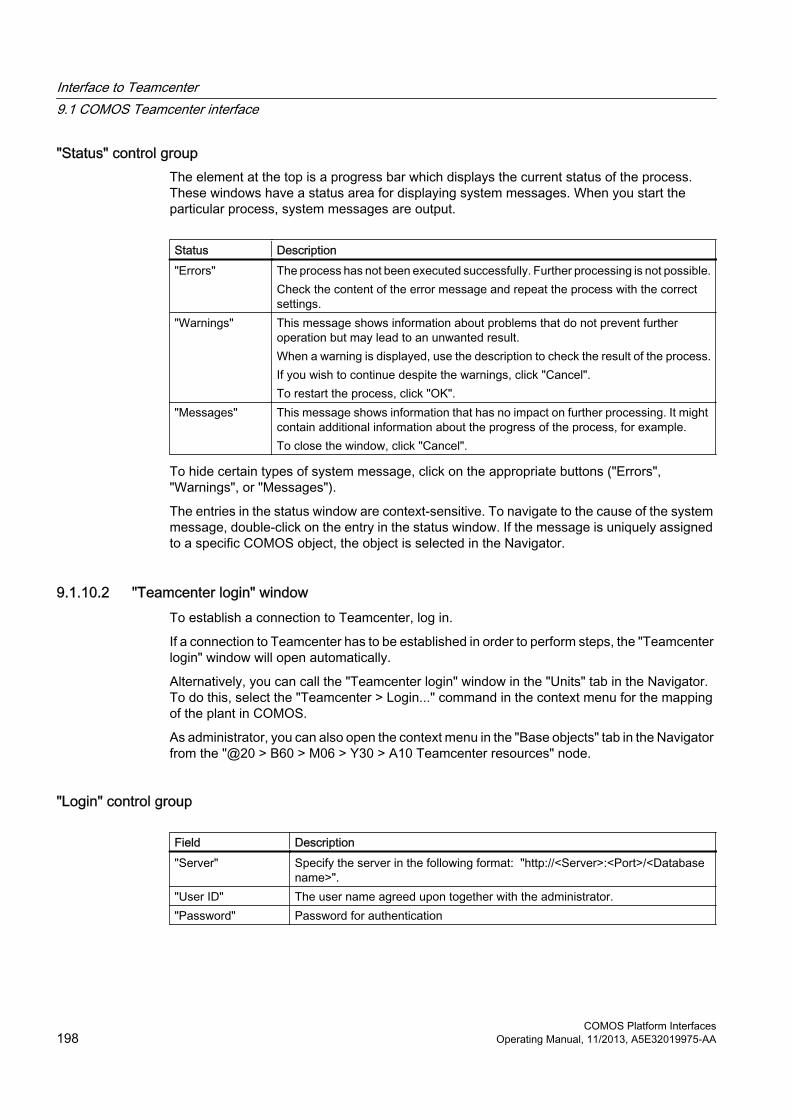
"Status" control groupThe element at the top is a progress bar which displays the current status of the process. These windows have a status area for displaying system messages. When you start the particular process, system messages are output.
Status Description"Errors" The process has not been executed successfully. Further processing is not possible.
Check the content of the error message and repeat the process with the correct settings.
"Warnings" This message shows information about problems that do not prevent further operation but may lead to an unwanted result. When a warning is displayed, use the description to check the result of the process.If you wish to continue despite the warnings, click "Cancel". To restart the process, click "OK".
"Messages" This message shows information that has no impact on further processing. It might contain additional information about the progress of the process, for example. To close the window, click "Cancel".
To hide certain types of system message, click on the appropriate buttons ("Errors", "Warnings", or "Messages").
The entries in the status window are context-sensitive. To navigate to the cause of the system message, double-click on the entry in the status window. If the message is uniquely assigned to a specific COMOS object, the object is selected in the Navigator.
9.1.10.2 "Teamcenter login" windowTo establish a connection to Teamcenter, log in.
If a connection to Teamcenter has to be established in order to perform steps, the "Teamcenter login" window will open automatically.
Alternatively, you can call the "Teamcenter login" window in the "Units" tab in the Navigator. To do this, select the "Teamcenter > Login..." command in the context menu for the mapping of the plant in COMOS.
As administrator, you can also open the context menu in the "Base objects" tab in the Navigator from the "@20 > B60 > M06 > Y30 > A10 Teamcenter resources" node.
"Login" control group
Field Description"Server" Specify the server in the following format: "http://<Server>:<Port>/<Database
name>"."User ID" The user name agreed upon together with the administrator."Password" Password for authentication
Interface to Teamcenter9.1 COMOS Teamcenter interface
COMOS Platform Interfaces198 Operating Manual, 11/2013, A5E32019975-AA

Field Description"Group" This field is optional and shows the group membership in the Teamcenter
organization structure as it is stored in Teamcenter."Role" This field is optional and shows the role in the selected group, if it deviates from
the default role. The data is shown as they are stored in Teamcenter.
"Status" control groupSee also chapter Status area in windows (Page 197).
Buttons
Button Description"OK" Click on this button to start the login process."Cancel" Use this button to cancel the login process.
9.1.10.3 "Synchronize plant from Tc" window
"Project" control group
Control element Description"Server URI" field Shows the connection to the current Teamcenter server."Project selection" list
Select the desired project.The previously selected project is preset.To select a different project, show the list by clicking the "Project selection" button.
"Current project" field Shows the current project."Incremental update" option
If you want to retain existing data, activate this option. This option is only available for the first execution.
"Create working layer" option
If you want to create transferred data on a separate working layer, activate this option.
"Status" control groupSee also chapter Status area in windows (Page 197).
Buttons
Button Description"OK" Starts the synchronization process from Teamcenter"Cancel" Cancels the synchronization.
Interface to Teamcenter9.1 COMOS Teamcenter interface
COMOS Platform InterfacesOperating Manual, 11/2013, A5E32019975-AA 199

9.1.10.4 "Synchronize plant to Tc" window
"Project" control group
Control element Description"Server URI" field Shows the connection to the current Teamcenter server."Project selection" list
Select the desired project.The previously selected project is preset.To select a different project, show the list by clicking the "Project selection" button.
"Current project" field Shows the current project.
"Status" control groupSee also chapter Status area in windows (Page 197).
Buttons
Button Description"OK" Starts the synchronization process to Teamcenter"Cancel" Cancels the synchronization.
9.1.10.5 "Element properties" window
"COMOS instance" control group
Field Description"Name" Shows the name assigned in COMOS.
"Teamcenter instance" control group
Control element Description"Item ID" field If you click the "Assign" button, the field is automatically filled with a valid value.
A 6-digit consecutive number is assigned by default. Alternatively, you can enter a text for identifying the object in Teamcenter.
"Revision ID" field If you click the "Assign" button, the field is automatically filled with a valid value. By default, the letter "A" is assigned for the first revision. Alternatively, you can enter text for identifying the first revision in Teamcenter.
"Assign" button Automatically fills the the "Item ID" and "Revision ID" fields with valid values assigned by the Teamcenter server.
"Name" field Free text for designating the object in Teamcenter.
Interface to Teamcenter9.1 COMOS Teamcenter interface
COMOS Platform Interfaces200 Operating Manual, 11/2013, A5E32019975-AA

Control element Description"Type" field Shows the resource or type to which the base object is assigned."Description" field Shows the description.
"Teamcenter position" control group
Field Description"Name" Name of the position of the object in the Teamcenter plant."Quantity" Frequency of the object at the position in the Teamcenter plant.
"Status" control groupSee also chapter Status area in windows (Page 197).
9.1.10.6 "Select Tc resource" window
Working areaSelect a resource to be the instance mapping for the reference object via the working area. Only resources whose resource assignment points to the reference object are displayed.
"Remove pointer" buttonTo remove the existing instance mapping, click on the "Remove pointer" button and then click "OK".
9.1.10.7 "Element properties" window in the base objects
"COMOS instance" control group
Field Description"Name" The name of the element is displayed in this field.
"Teamcenter instance" control group
Field Description"Item ID" If the resource information has been synchronized, the data from Teamcenter
is entered automatically in these fields."Revision ID""Name""Type""Description"
Interface to Teamcenter9.1 COMOS Teamcenter interface
COMOS Platform InterfacesOperating Manual, 11/2013, A5E32019975-AA 201

9.1.10.8 "Synchronize resource info" window
"Project" control group
Control element Description"Server URI" field Shows the connection to the current Teamcenter server. "Project name" field Shows the current project name."Create working layer" option
If you want to create transferred data on a separate working layer, activate this option.
"Status" control groupSee also chapter Status area in windows (Page 197).
9.1.10.9 "Teamcenter units of measurement" tab
Table
Column Description"Name" Non-editable field
The text in this field indicates the unit of measurement used in Teamcenter. To clarify the origin, the units of measurement from Teamcenter are prefixed with "CTI_".
"Description" Non-editable fieldThis field contains the description text saved in COMOS.
"COMOS unit" Editable field provided for the unit of measurement used in COMOS.● If there is an entry in this field, you have already assigned a COMOS unit of
measurement to the text used in Teamcenter.● If this field is empty, assign a COMOS unit of measurement to the text used
in Teamcenter.
9.1.10.10 "CTI resource mapping" tab
Tab
Control element Description"Mapped base object" field
Drag&drop the required object into this field to make the assignment. A suitable base object must contain the "Y00T00128 CTI instance mapping" tab.
"Resource properties" button
Click this button to view entries for the resource from Teamcenter. The "Element properties" window opens. See also chapter "Element properties" window (Page 200).
Interface to Teamcenter9.1 COMOS Teamcenter interface
COMOS Platform Interfaces202 Operating Manual, 11/2013, A5E32019975-AA

9.1.10.11 "CTI attribute mapping" tab
Button
Name Description"Update values ..." When you click this button, the "Update values" window is called up. By clicking
"OK", you start the transfer from this window of the values synchronized from Teamcenter to the corresponding COMOS attributes based on the attribute mapping.
Table
Column Description"Tc description" Non-editable field
This field contains a short descriptive text that is synchronized to COMOS from Teamcenter with the attribute.
"Tc value" Non-editable field The "Tc value" column displays the value of the attribute as it was synchronized from Teamcenter.
"Tc unit" Non-editable fieldThe "Tc unit" column displays information about the unit of measurement as stored in Teamcenter.
"Attribute mapping" Here, you can assign an attribute. If you want to assign an attribute, use drag&drop to move it from the assigned resource or its inheritance source into the "Attribute mapping" field.
"Attribute unit" Non-editable fieldThis field displays the unit of measurement in COMOS.
9.1.10.12 "CTI instance mapping" tab
Control elements
Control element Description"Assigned Tc resource" field
Shows the assigned Teamcenter resource.
"Instance properties ..." button
The user needs this button when creating an engineering object based on the reference object.
"Select Tc resource" button
To select a Teamcenter resource, click this button. Only those resources to which the reference object is assigned are listed for selection. The default value is the first resource to which the reference object was assigned.
Interface to Teamcenter9.1 COMOS Teamcenter interface
COMOS Platform InterfacesOperating Manual, 11/2013, A5E32019975-AA 203

9.2 Process Data Interface (PDI)
9.2.1 Introduction
Process Data Interface (PDI)Pipe parts are transferred from COMOS to NX via PDI. The data is transferred via Teamcenter to NX. Teamcenter is the interface for the data transfer between COMOS and NX. Transferring takes place by means of XML files in which the information about pipe specs and pipe parts is collected.
Pipe schedules are transferred as PDFs. Information about PipeRun and XMplant is also transferred as an XML file.
Teamcenter versionTo use the functions of PDI, you need to use Teamcenter version 9.1 and NX version 9.0.
9.2.2 Using PDI
9.2.2.1 Connection between COMOS and NX
Requirements for the connectionYou have access to COMOS and NX from your workplace. COMOS and NX communicate through a directory. You have to have access to this directory. If you are working with Windows 7, ensure also that you start COMOS with administrator rights.
Both systems have to be configured so that the connection between COMOS and NX functions. See chapter ""Comos.PDI.config" configuration file (Page 211)".
9.2.2.2 Exporting pipe specs to Teamcenter
Requirement● You have write rights for the base project.
● The pipe specs have already been created and configured.
● The XML file "pipepartfamilies" exists. See chapter XML file "pipepartfamilies" (Page 212).
● The NX template is assigned, meaning that the pipe parts have already been created and configured.
Interface to Teamcenter9.2 Process Data Interface (PDI)
COMOS Platform Interfaces204 Operating Manual, 11/2013, A5E32019975-AA

NoteAssigning pipe parts
No assignment of pipe parts is supplied with the database. See also chapter Assigning objects (Page 207).
Procedure1. Open the base project.
2. Navigate to the desired pipe spec.
3. Select the "Teamcenter > Export pipe spec to Teamcenter" command from the context menu.
4. If you are not yet logged in, log in to Teamcenter in the "Teamcenter login" window.Various windows help you in the export process. Click the "Cancel" button to stop the process. Initially, a window with the pipe part catalog and the pipe specs is displayed. You can compare the last version of the data with the current version.
5. Check the information and click "Next".
6. Click "Next" in the "XMLViewer" window. See also chapter "XMLViewer" window (Page 209).
7. To export the pipe specs, click the "Transfer" button.
ResultAfter the transfer to Teamcenter has been completed, a corresponding notice is displayed. Two XML files are generated that are transferred to Teamcenter. The XML files contain information about the pipe specs and the pipe part catalog. Teamcenter stores the files under "Home > PDI" with the name of the pipe spec. "Home" is the node of the same name of the user with which you logged in.
9.2.2.3 Publishing documents
RequirementThe corresponding settings for your document and the project have been carried out. See chapter "Checking the settings of the document base object (Page 212)" and ""Comos.PDI.config" configuration file (Page 211)".
Procedure1. Open the properties of the desired document.
2. Select the tab "Revisions".
3. Click the "Creates a new revision" button.
Interface to Teamcenter9.2 Process Data Interface (PDI)
COMOS Platform InterfacesOperating Manual, 11/2013, A5E32019975-AA 205

4. Click the "Yes" button in the "Create revision" window.
5. Expand the "Created by" button and select the "Released by" entry.If no connection to the Teamcenter is in place, the "Teamcenter Login" window is shown.
6. If you are not already logged in, enter your access data and click "OK".
ResultThe following files are generated automatically and transferred to the Teamcenter:
● PDF file
● XML file "Piperun"
● XML file "XMpLant"
The target documents are saved as records under the revision of a document in the "PDI" folder in Teamcenter.
If a counterpart of the published COMOS document already exists in Teamcenter, that transferred documents are stored under a new revision of the counterpart. Otherwise, a new document including initial revision is created in the Teamcenter.
9.2.2.4 Connecting COMOS and NX
RequirementThe connection between COMOS and NX is configured. See also chapter "Comos.PDI.config" configuration file (Page 211). NX is opened.
Procedure1. Open COMOS.
2. Select a P&ID in the Navigator.
3. Open the context menu.
4. Select the "Teamcenter > Start cross selection" command.
5. Switch to NX.
6. Select the menu entry "Tools > Schematics > Connect" in the main menu "Tools".
ResultWhen the connection has been established successfully, you have the following possibilities on the P&ID:
● Connecting objects
● Navigating to the object in NX
● Disconnecting the connection between the objects
Interface to Teamcenter9.2 Process Data Interface (PDI)
COMOS Platform Interfaces206 Operating Manual, 11/2013, A5E32019975-AA

9.2.2.5 Disconnecting the connection between COMOS and NX
RequirementCOMOS and NX are connected. See chapter "Connecting COMOS and NX (Page 206)".
Procedure1. Switch to NX.
2. Select the menu entry "Tools > Schematics > Disconnect" in the main menu "Tools".
Alternative procedure1. Switch to COMOS.
2. In the context menu of the P&ID, select the command "Teamcenter > Stop cross-selection".
9.2.2.6 Assigning objects
RequirementCOMOS and NX are connected. See chapter "Connecting COMOS and NX (Page 206)".
Procedure1. Open a P&ID.
2. Select a P&ID object and open the context menu.
3. Select the "Teamcenter > Assign" command.If the object has already been implemented, NX updates the assignment between the P&ID object and the COMOS object.
4. Switch to NX.If no object is displayed highlighted, the "Assign Component" window is displayed.
5. Select the desired object.
ResultYou can check the assignment in the context menu of the selected object in NX under the entry "Properties". You can also only navigate to assigned objects between Nx and COMOS.
9.2.2.7 Canceling the assignment
RequirementCOMOS and NX are connected. See chapter "Connecting COMOS and NX (Page 206)".
Interface to Teamcenter9.2 Process Data Interface (PDI)
COMOS Platform InterfacesOperating Manual, 11/2013, A5E32019975-AA 207
Procedure1. Select the desired object on the P&ID in COMOS.
2. Select the "Teamcenter > Unassign" command from the context menu.
Alternative procedure1. Select the desired object in NX.
2. Select the menu entry "Tools > Schematics > Unassign" in the main menu "Tools".
ResultThe assignment is canceled; you can no longer navigate between the respective object in Nx and COMOS.
9.2.2.8 Navigating to the 3D object in NX
Requirement● COMOS and NX are connected. See chapter "Connecting COMOS and NX (Page 206)".
● The object is assigned. See chapter Assigning objects (Page 207).
● The P&ID is open.
Procedure1. Select the required object on the P&ID.
2. Select the entry "Teamcenter > Navigate to NX" in the context menu.
3. Switch to NX.
ResultThe corresponding object is centered in NX and highlighted.
9.2.2.9 Navigating to the COMOS object on the P&ID
Requirement● COMOS and NX are connected. See chapter Connecting COMOS and NX (Page 206).
● The object is assigned. See chapter Auto-Hotspot.
Interface to Teamcenter9.2 Process Data Interface (PDI)
COMOS Platform Interfaces208 Operating Manual, 11/2013, A5E32019975-AA

Procedure1. Select the object in NX.
2. Select the menu entry "Tools > Schematics > Navigate to PID Symbol" in the main menu "Tools".
3. Switch to COMOS.
ResultThe corresponding object is highlighted on the P&ID (piping and instrumentation diagram) in COMOS.
9.2.3 "XMLViewer" window
9.2.3.1 Views
IntroductionBefore transferring a pipe to Teamcenter, you can view the generated files in the "XMLViewer" window. You cannot make changes in this window. The XMLViewer is used for the final data check before transfer. Recommendation: If abnormalities occur, cancel the transfer and make the appropriate improvements in COMOS. The following functions are available in the "XMLViewer" window:
● View of pipe spec specification in XML format
● View of the pipe part catalog in XML formatThe views of pipe parts/pipe specs appear automatically one after the other. You cannot go back to a previous view. You can call a version comparison in each case.
● Version comparison of generated files
● Confirmation of file transfer
OverviewThe window "XMLViewer" has the same layout in every view.
The path to the generated and displayed file is shown at the top of the window. The symbol bar contains the buttons which you use to switch between the views. The file data is shown as content. Display of the content depends on which view you have selected. See also chapter Calling a view (Page 210).
Interface to Teamcenter9.2 Process Data Interface (PDI)
COMOS Platform InterfacesOperating Manual, 11/2013, A5E32019975-AA 209

ViewsYou can call the following views:
View Description"XML table" Tabular display of the data prepared for export"Normal XML format" Display of the generated file in XML format"Version comparison" This display shows the differences between two versions of
a pipe spec. The current version is always compared to the previous version.See also chapter Version comparison (Page 210).
9.2.3.2 Calling a view
ProcedureSelect one of the following options:
● To call the "XML table" view, click the button.
● To call the "Normal XML format" view, click the button.
● To call the "Version comparison" view, click the button.
9.2.3.3 Version comparison
Displaying the changesThe "Version comparison" view is divided into three content areas:
Content area Description"Before" Shows the specific contents of the previously generated XML
file. This older version is the basis for the comparison. If all areas are empty, the contents are identical.
"Current" Displays the content of the currently generated XML file."Differences" Shows the discrepancies between the two versions. The
result is displayed in a table.
Table in the "Differences" content area
Column Description"Current element names" List of all XML root elements which deviate."Comparison element names" List of XML elements which contain differences between two
versions."Comparison result" Shows a description of differences.
Interface to Teamcenter9.2 Process Data Interface (PDI)
COMOS Platform Interfaces210 Operating Manual, 11/2013, A5E32019975-AA

Column Description"Current element content" Shows the content of the XML element in the previous version."Comparison element content" Shows the content of the XML element to be compared in the
current version.
9.2.4 Administering PDI
9.2.4.1 "Comos.PDI.config" configuration file
Settings in the configuration fileYou configure the usage of the Teamcenter interface or of PDI using the "Comos.PDI.config" configuration file. This file is located in the "config\pdi" folder of the COMOS installation directory.
To use the Teamcenter interface, enter the following key in the configuration file between the entries <appSettings></appSettings>: <add key="RevisionType" value="CTI" />
To start PDI, also enter the value "1" in the <add key="StartInterface" key: <add key="StartInterface" value="1" />Furthermore, enter the exchange folder in the configuration file.
Example<add key="SharedFolder" value="C:\Temp\SchematicsExchangeDir" />Configure NX accordingly so that the same directory is used.
9.2.4.2 Checking the settings of the revision printerIn order to publish documents, the corresponding settings must have been made. Check the relevant settings before publishing a document for the first time or if errors occur.
Procedure1. Open the project properties.
2. Select the "General settings > Revision options" category.
3. Check in the "Settings" control group whether the "PDFFactory (as of v. 1.5x)" entry has been selected in the "Revision archive" list.
Interface to Teamcenter9.2 Process Data Interface (PDI)
COMOS Platform InterfacesOperating Manual, 11/2013, A5E32019975-AA 211

9.2.4.3 Checking the settings of the document base object
Procedure1. Select the desired document in the Navigator.
2. Navigate to the base object.
3. Open the base object properties.
4. To check the setting, select the "System" tab.
5. Check in the "Miscellaneous" control group whether the "Teamcenter revision" entry has been selected in the "Revision type" list.
9.2.4.4 XML file "pipepartfamilies"
GeneralThe XML file "pipepartfamilies" is located in the installation directory of COMOS in the "config\pdi" folder.
A pipe part family from NX has to be mapped for each pipe part in COMOS. The pipe part family categorizes pipe parts. The mapping is saved in the XML family. The mapping can be edited in the file "pipepartfamilies.xml" either in COMOS or via an XML editor.
RecommendationEdit the content of the XML file only in COMOS. See chapter "Editing the XML file "pipepartfamilies" (Page 212)".
9.2.4.5 Editing the XML file "pipepartfamilies"
Procedure1. Open the base project in COMOS.
2. Navigate to a pipe spec.
3. Select a pipe part lying under it.
4. Select the "Teamcenter > Map attribute configuration" command from the context menu.
5. Carry out the required changes in the "Pipe part attribute mapping" window:
– See chapter "Adding an attribute (Page 213)".
– See chapter "Editing an attribute (Page 213)".
– See chapter "Deleting an attribute (Page 214)".
6. Click "OK".
Interface to Teamcenter9.2 Process Data Interface (PDI)
COMOS Platform Interfaces212 Operating Manual, 11/2013, A5E32019975-AA

9.2.4.6 Configuration of the "Pipe part attribute mapping" window
Overview
Control group Description"ID Mask" This displays the information on how the ID of the pipe part
is generated."Nx template" This list contains all the pipe part families that are supported
by PDI. You can change the pipe part family for the selected pipe part.
"Text Based Attributes" This table contains all the family attributes with values as text."General Attributes" This table contains family attributes that have no connection
to the geometry of the pipe part."Geometry Attributes" This table contains all the attributes of the selected pipe part
with a connection to geometry. In the "Check" column, you set whether a value is interpreted as valid or not by PDI. At invalid values, the respective checkbox is cleared and the pipe part is not exported.
9.2.4.7 Adding an attribute
RequirementYou have called up the "Pipe part attribute mapping" window. See chapter "Editing the XML file "pipepartfamilies" (Page 212)".
Procedure1. Right-click under a table.
2. Select the "Add row" command.
3. Enter the desired information in the "Pipe part attribute mapping" window.
4. Click "OK".
9.2.4.8 Editing an attribute
RequirementYou have called up the "Pipe part attribute mapping" window. See chapter "Editing the XML file "pipepartfamilies" (Page 212)".
Procedure1. Right-click the desired attribute.
2. Select the "Edit row" command from the context menu.
Interface to Teamcenter9.2 Process Data Interface (PDI)
COMOS Platform InterfacesOperating Manual, 11/2013, A5E32019975-AA 213

3. Carry out the required changes in the "Pipe part attribute mapping" window.
4. Click "OK".
9.2.4.9 Deleting an attribute
RequirementYou have called up the "Pipe part attribute mapping" window. See chapter "Editing the XML file "pipepartfamilies" (Page 212)".
Procedure1. Right-click the desired attribute.
2. Select the "Remove row" command from the context menu.
Interface to Teamcenter9.2 Process Data Interface (PDI)
COMOS Platform Interfaces214 Operating Manual, 11/2013, A5E32019975-AA