comp 1121: computers and computer networks session 5: network topologies and routing
TRANSCRIPT
COMP 1121: Computers and Computer Networks
Session 5: Network Topologies and Routing
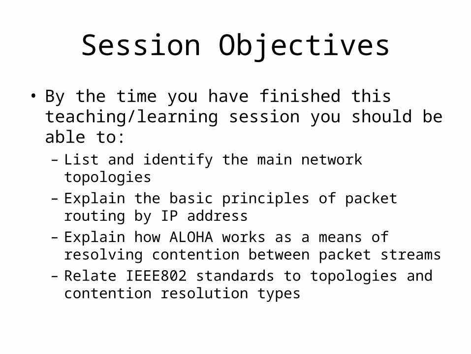
Session Objectives
• By the time you have finished this teaching/learning session you should be able to:– List and identify the main network topologies– Explain the basic principles of packet routing by IP
address– Explain how ALOHA works as a means of resolving
contention between packet streams– Relate IEEE802 standards to topologies and
contention resolution types
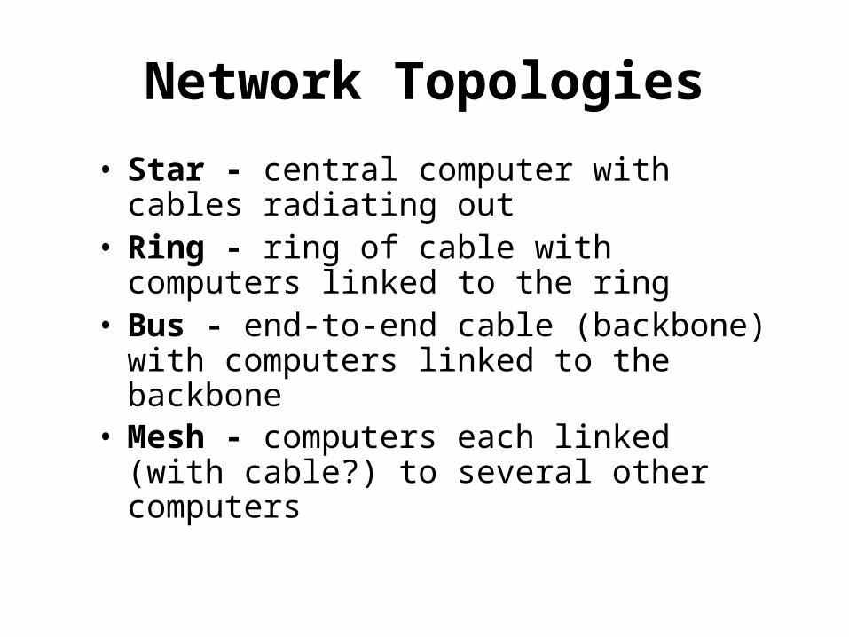
Network Topologies
• Star - central computer with cables radiating out
• Ring - ring of cable with computers linked to the ring
• Bus - end-to-end cable (backbone) with computers linked to the backbone
• Mesh - computers each linked (with cable?) to several other computers
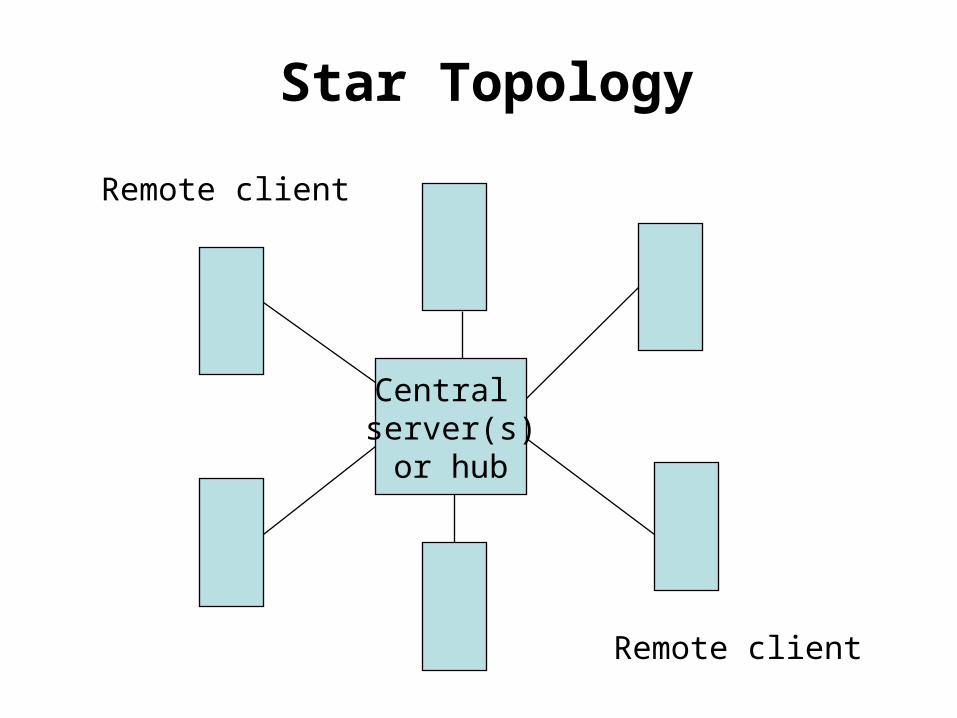
Star Topology
Central server(s)
or hub
Remote client
Remote client
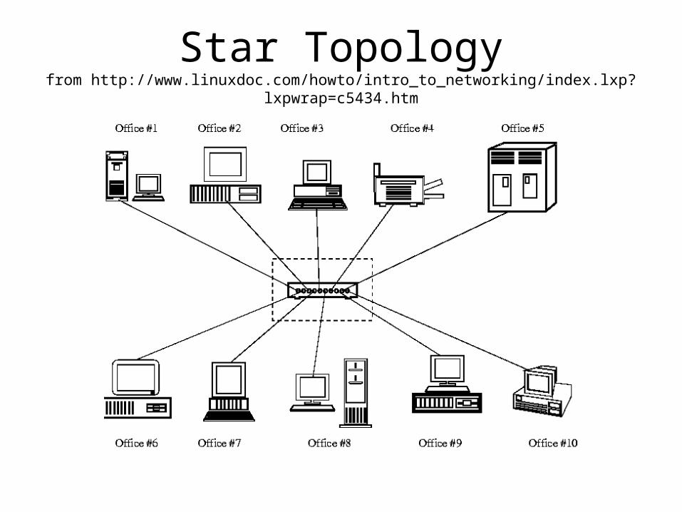
Star Topologyfrom http://www.linuxdoc.com/howto/intro_to_networking/index.lxp?lxpwrap=c5434.htm
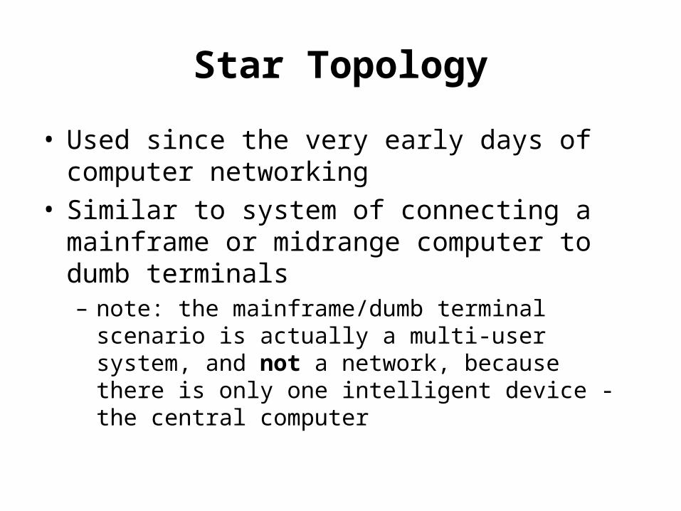
Star Topology
• Used since the very early days of computer networking
• Similar to system of connecting a mainframe or midrange computer to dumb terminals– note: the mainframe/dumb terminal scenario is
actually a multi-user system, and not a network, because there is only one intelligent device - the central computer
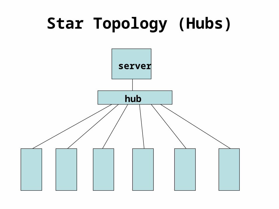
Star Topology (Hubs)
hub
server
Star Topology (Hubs)
• All nodes connected to a common central location, known as a hub
• Hubs can link to other secondary hubs, creating subnets
• All packets of data transferred through the network go through the main hub– Therefore it must have a high
bandwidth
Star Topology (Hubs)
• Quite fault tolerant because:– If one network link fails…– only a single node loses connection
• However, if the hub itself fails then the whole subnet/network fails!
Ring Topology
• no central hub• data from one node:
– passes into a “ring” of cabling– travels round the ring
• Mechanism:– every node receives all network data– takes the data that is addressed to it– passes the rest back to the ring
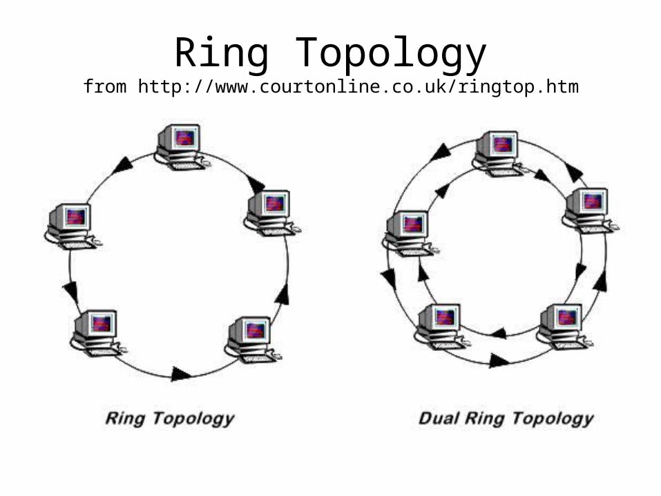
Ring Topologyfrom http://www.courtonline.co.uk/ringtop.htm
Ring Topology
• Evaluation– If a node fails or a cable breaks, the whole
ring could fail– “monitor stations” are therefore used to
quickly detect failures– If data does not find its destination node, it
will pass right round the ring until it returns to its originator
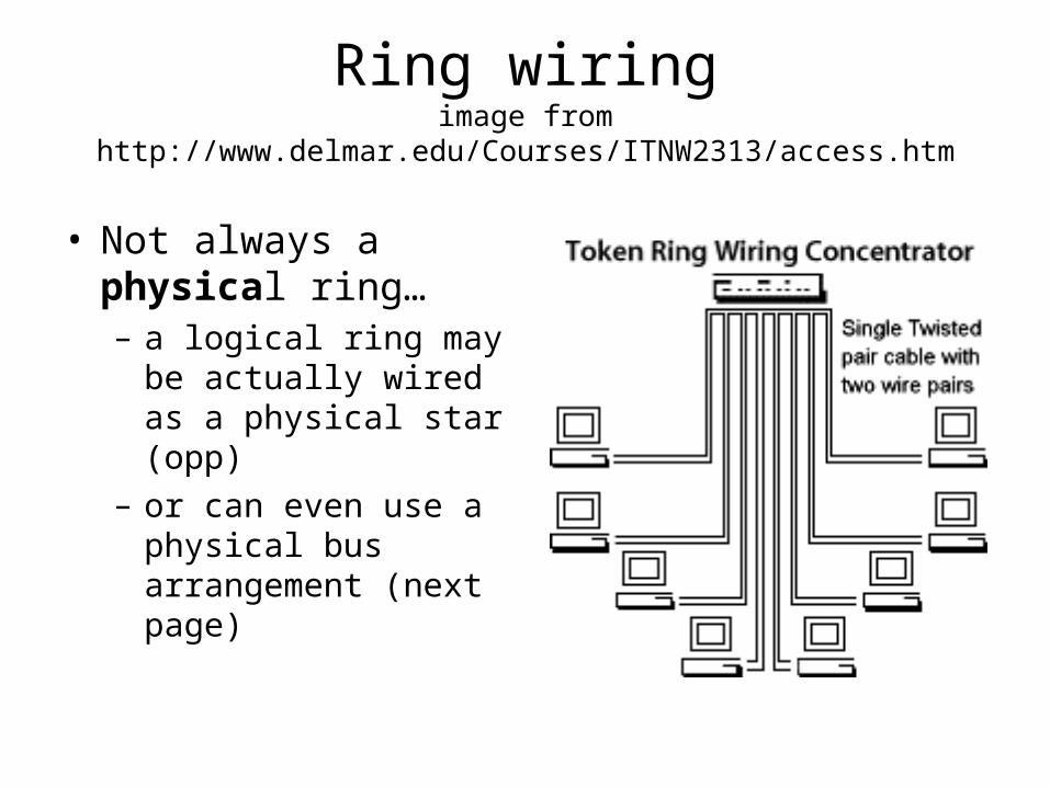
Ring wiringimage from http://www.delmar.edu/Courses/ITNW2313/access.htm
• Not always a physical ring…– a logical ring may be
actually wired as a physical star (opp)
– or can even use a physical bus arrangement (next page)
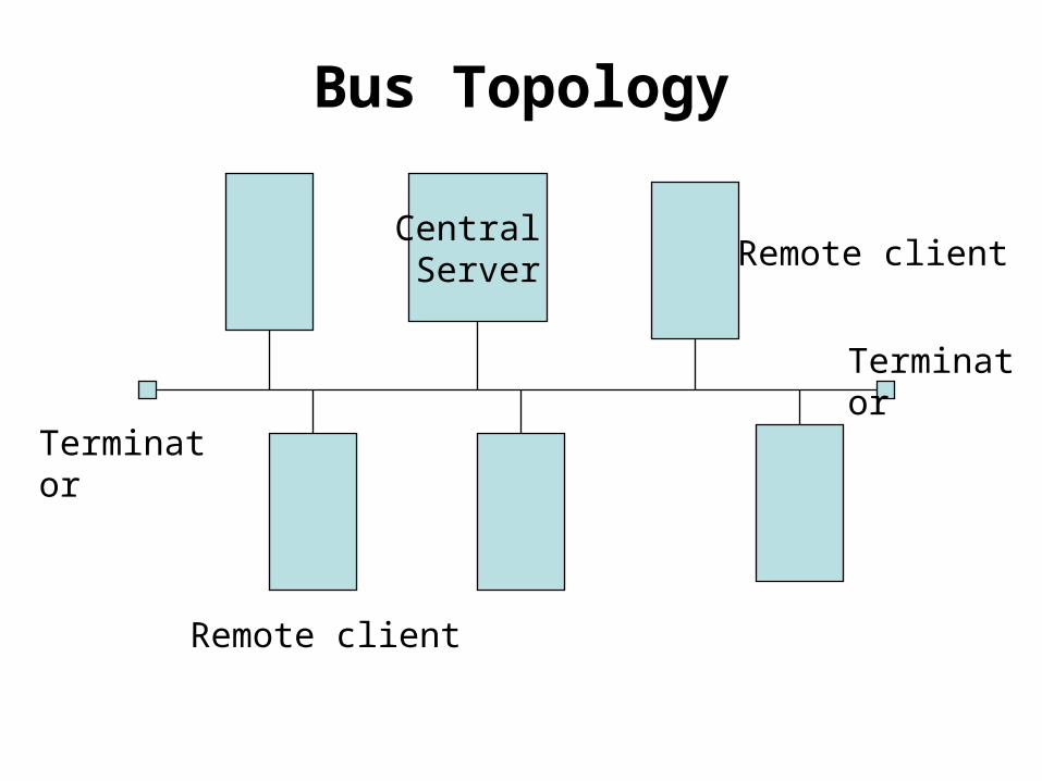
Bus Topology
Central Server
Remote client
Remote client
Terminator
Terminator
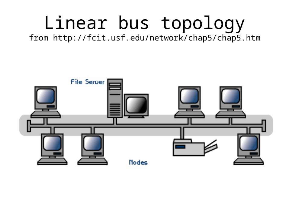
Linear bus topologyfrom http://fcit.usf.edu/network/chap5/chap5.htm
Bus Topology
• Once Popular technology for small (<20 computers) networks
• T-pieces electrically connect computers to the backbone
• Bus carries all network data• All nodes are connected to a single common
cable known as the backbone• The backbone is end-to-end, and a terminator
is needed at each end to prevent signal bounce and to complete the circuit
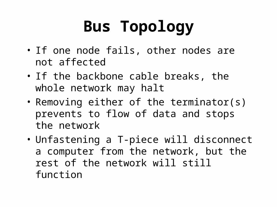
Bus Topology
• If one node fails, other nodes are not affected• If the backbone cable breaks, the whole
network may halt• Removing either of the terminator(s) prevents
to flow of data and stops the network• Unfastening a T-piece will disconnect a
computer from the network, but the rest of the network will still function
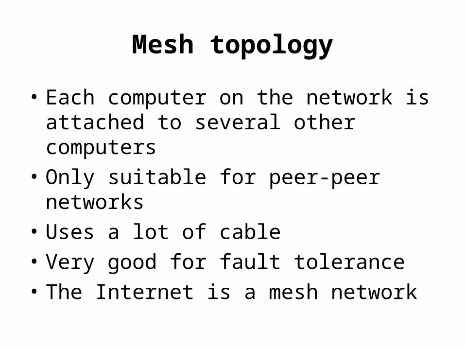
Mesh topology
• Each computer on the network is attached to several other computers
• Only suitable for peer-peer networks
• Uses a lot of cable
• Very good for fault tolerance
• The Internet is a mesh network
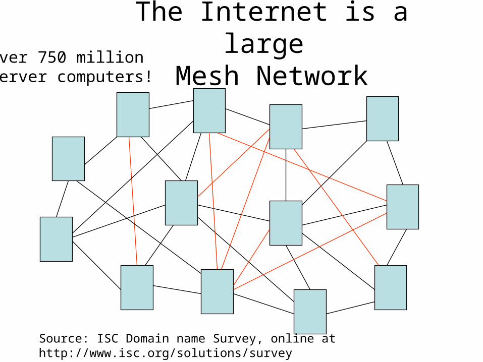
The Internet is a large Mesh NetworkOver 750 million
Server computers!
Source: ISC Domain name Survey, online at http://www.isc.org/solutions/survey
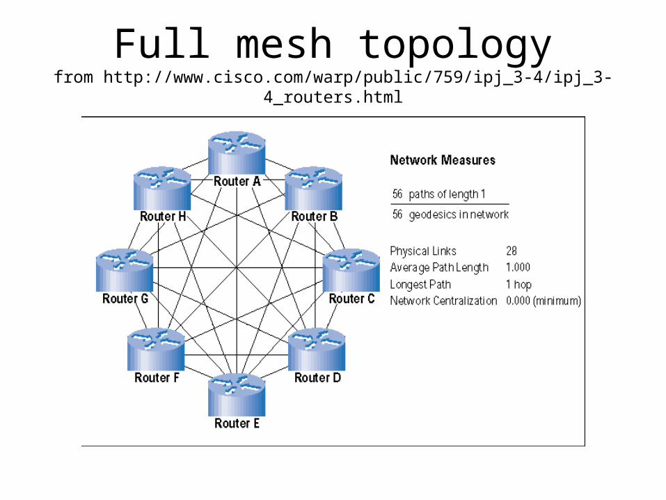
Full mesh topologyfrom http://www.cisco.com/warp/public/759/ipj_3-4/ipj_3-4_routers.html
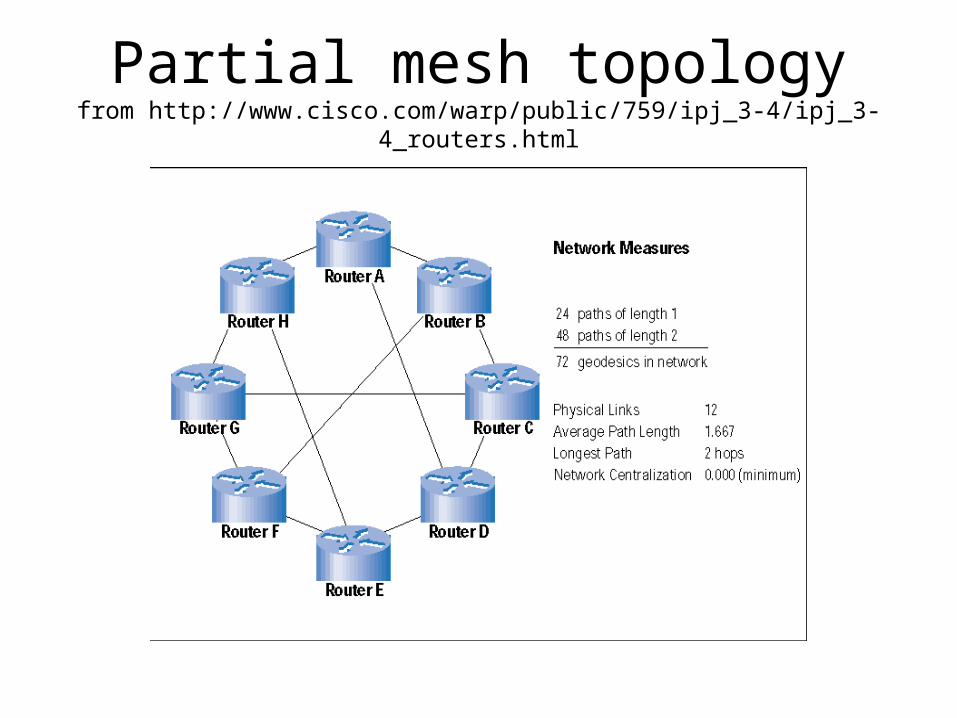
Partial mesh topologyfrom http://www.cisco.com/warp/public/759/ipj_3-4/ipj_3-4_routers.html
Mesh Topology (3)
• How many links are needed to connect together 3 nodes in a full mesh?
• 4 nodes?
• 5 nodes?
• 10 nodes?
• 1000 nodes?
Routing
• Problem: how to get a message from one computer to another
• Needs a means of identifying the destination– IP address, or similar
• And a means of finding that destination– calculating/choosing a pathway to the
destination through the network
Types of routing 1:Broadcast Routing (e.g. Ethernet)
• Message is sent to all computers in the subnet
• Only the computer to which it is addressed bothers to read its contents
• Uses MAC addresses (unique identifier of the NIC, function at OSI layer 2)
• Useful on small local networks• Uses too much bandwidth for large
networks
Types of routing 2:Addressed routing
• Uses IP addresses or something similar
• Each packet has destination address information in its header
• Packet is passed from router to router towards its destination– and eventually arrives…
• Used on the Internet and other large networks
Media Access (OSI layers 1 & 2)
• All network topologies require that network devices use a common carrier medium to access network resources– e.g. copper cabling, optical fibre, radio waves
• If packets from different sources arrive at the carrier simultaneously, there will be big problems…
• This basic media access issue is known as contention– particular problem with broadcast networks
Collisions
• Transmission of a data packet takes a finite time
• Travel of the whole packet to the furthest point on the network takes a further finite time
• If, at any time during this period, another host on the network starts to transmit, there will be other hosts that receive parts of both packets simultaneously
• Result: neither packet can be received properly
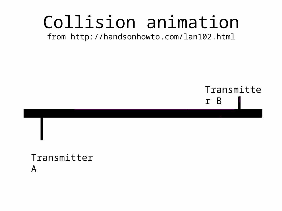
Collision animationfrom http://handsonhowto.com/lan102.html
Transmitter A
Transmitter B
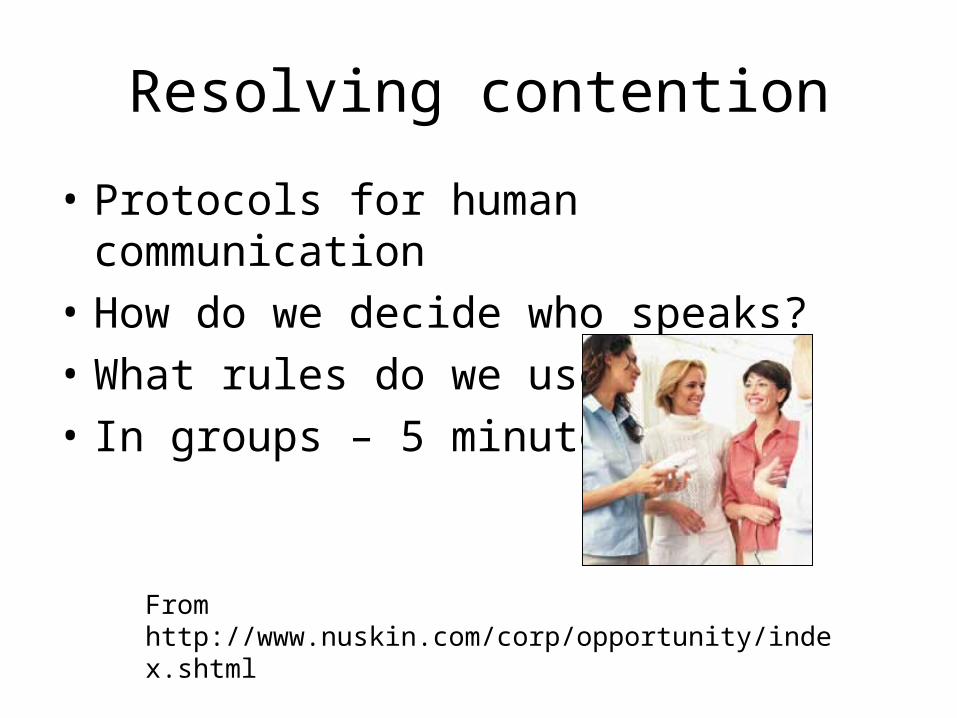
Resolving contention
• Protocols for human communication
• How do we decide who speaks?
• What rules do we use?
• In groups – 5 minutes
From http://www.nuskin.com/corp/opportunity/index.shtml
Resolving Contention
• A number of possible solutions have been devised to ensure packets do not collide:– Polling– Token Passing– ALOHA
Polling
• Central controller interrogates each node in turn and asks if it has a message to send
• If a message is waiting to be sent, it is delivered
• If no message, controller passes on to the next node
Token passing
• Software ‘token’ is passed from node to node in a predetermined order
• Nodes can only send messages when they are in possession of the token
• Token is passed to the next node in sequence when it is no longer needed– if no message is to be sent, or when the
message has been sent
Aloha (1)
• Named after Hawaiian greeting
• First used to connect several computers by radio in Hawaii– hard (cabled) links not practicable between
islands
• Rule:– each station transmits as and when needed
Aloha (2)
• If a collision occurs, messages are retransmitted after a random wait– If both stations retransmitted immediately, or
after a fixed interval, a further collision would occur
• OK for light traffic (and few collisions)
• Maximum efficiency possible about 18% due to collisions
Commercial Aloha – “Ethernet”
• Name derived from “the ether”– a hypothetical invisible substance that was
once thought to exist in space and allowed radio waves to be conducted through it (!)
• Ethernet name invented by Dr Graham Metcalfe, of Xerox– wanted to connect 100 computers together
over a 1km cable– used a system based on pure Aloha to
resolve contention
Ethernet & Network Contention
• Pure ALOHA allows nodes to attempt to broadcast at any time– Then manages the attempted broadcasts to ensure
that collisions are detected and dealt with by resending
• OK for lightly used network• But means that many workstations all working
concurrently on the same network segment can create a lot of collisions
• Result can be a severely reduced response time
Ethernet – reduction in collisions using CSMA (1)
• Carrier Sense Multiple Access (CSMA)
• Strategy used in broadcast systems to reduce the likelihood of collisions
• Each node listens before transmitting– if the medium is busy then the node waits– otherwise it transmits
Ethernet – reduction in collisions using CSMA (2)
• Problem: signals travel at a finite speed– So two nodes could begin to transmit almost
simultaneously– and not detect each other’s transmission
before starting their own message
• Solution: each node listens while transmitting to be sure that no other node starts transmitting
Ethernet and CSMA (3)
• If a collision is detected:– both nodes stop transmitting immediately
• It would be a waste of time to finish message that is corrupted…
– then wait a random time and retry (binary exponential backoff)
Ethernet and CSMA (4)
• Called unslotted or non-persistent CSMA• based on and replaces pure Aloha• Unslotted because any node can transmit at
any time– Some protocols only allow transmissions to start at
certain time – starts of ‘time ‘slots’
• Non-persistent because nodes wait before retrying– if they both tried to transmit again immediately,
they would cause another collision!
Full Ethernet model (CSMA/CD) (1)
• Pre-dated the OSI model!
• Provided an algorithm for the protocol for sending data that could be represented in the following way:
• Carrier Sense– The node “listens” to the carrier medium to
see if anyone is transmitting– If another node is transmitting, wait until it
has finished
Full Ethernet model (CSMA/CD) (2)
• Multiple Access– Many nodes are connected to the same carrier
medium
• Collision Detection– Each node listens during transmission– If a collision is detected during transmission, both
transmitting nodes will stop transmitting immediately and then retry after a random wait
– If collisions continue to occur, nodes extend their wait time
Collision detection?from http://www.dawndreamer.ca/photos_to_ponder.htm
Full Ethernet model (CSMA/CD) (3)
• With good design, this method can deliver 90% efficiency of bandwidth
• Main advantage is that time is not wasted in transmitting whole packets when a collision occurs
• Most bus networks now use CSMA/CD• Collisions can still cause problems if too
many workstations are connected to a single network segment– no means of prioritising
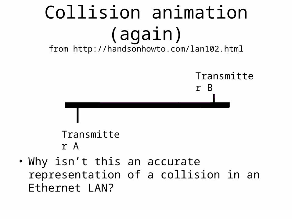
Collision animation (again)from http://handsonhowto.com/lan102.html
• Why isn’t this an accurate representation of a collision in an Ethernet LAN?
Transmitter B
Transmitter A
Ethernet
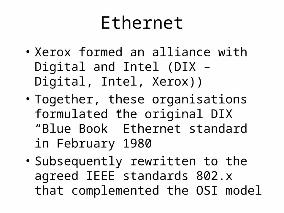
• Xerox formed an alliance with Digital and Intel (DIX – Digital, Intel, Xerox))
• Together, these organisations formulated the original DIX “Blue Book” Ethernet standard in February 1980
• Subsequently rewritten to the agreed IEEE standards 802.x that complemented the OSI model
Ethernet and OSI (1)
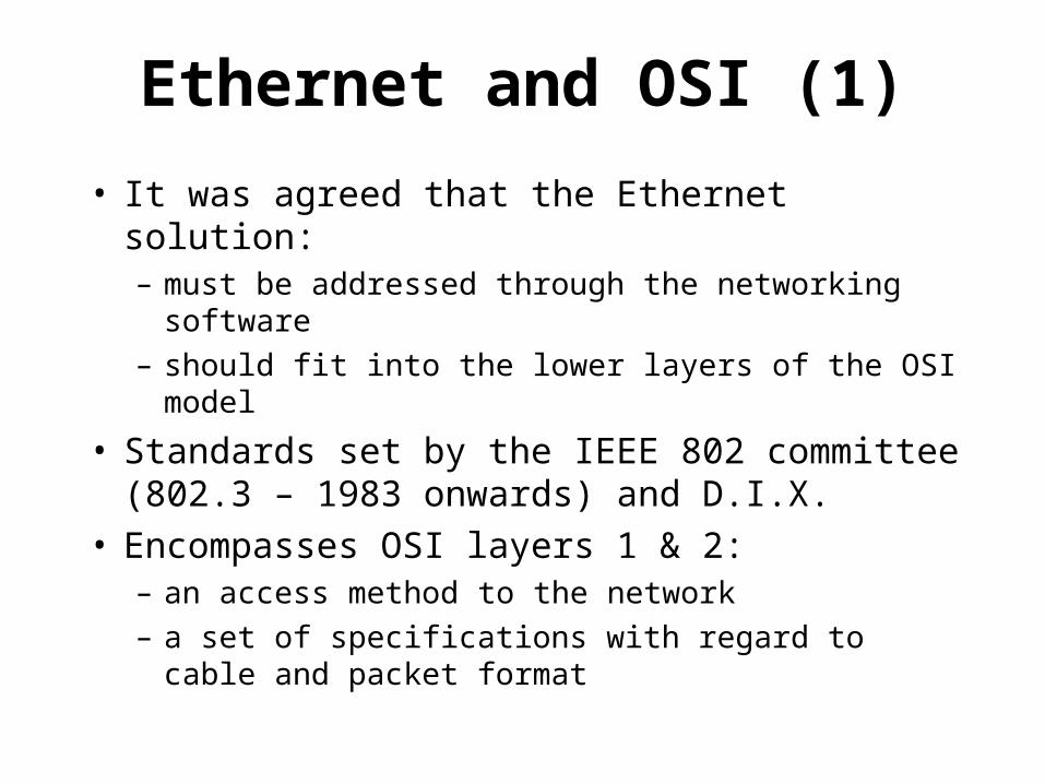
• It was agreed that the Ethernet solution:– must be addressed through the networking
software– should fit into the lower layers of the OSI model
• Standards set by the IEEE 802 committee (802.3 – 1983 onwards) and D.I.X.
• Encompasses OSI layers 1 & 2:– an access method to the network– a set of specifications with regard to cable and
packet format
Ethernet and OSI (2)
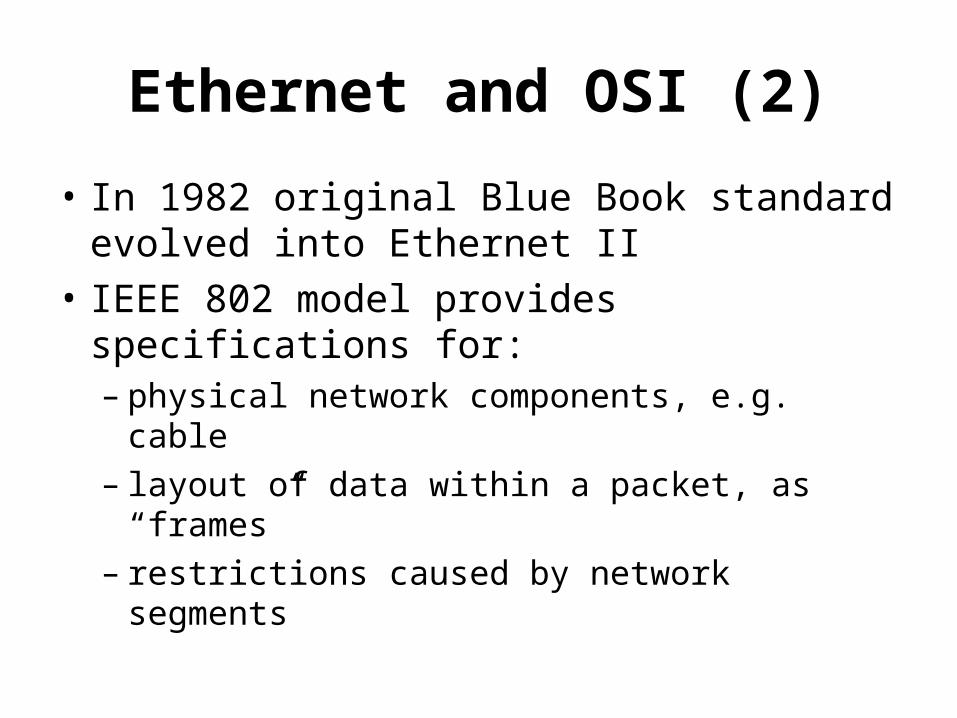
• In 1982 original Blue Book standard evolved into Ethernet II
• IEEE 802 model provides specifications for:– physical network components, e.g. cable– layout of data within a packet, as “frames”– restrictions caused by network segments
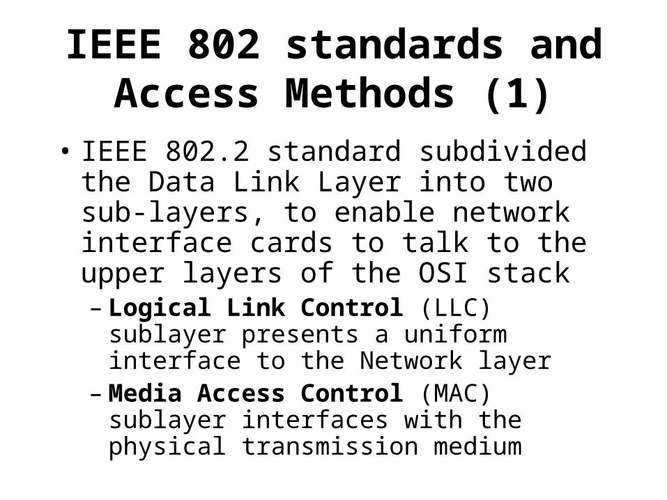
IEEE 802 standards and Access Methods (1)
• IEEE 802.2 standard subdivided the Data Link Layer into two sub-layers, to enable network interface cards to talk to the upper layers of the OSI stack– Logical Link Control (LLC) sublayer
presents a uniform interface to the Network layer
– Media Access Control (MAC) sublayer interfaces with the physical transmission medium
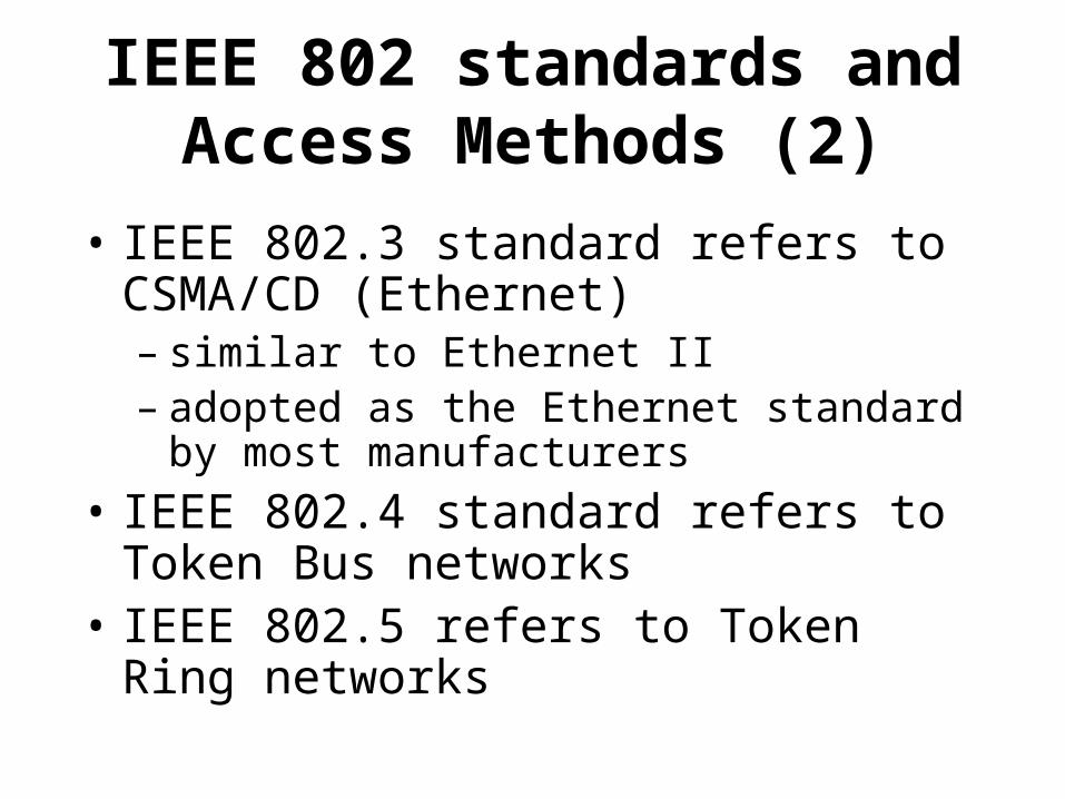
IEEE 802 standards and Access Methods (2)
• IEEE 802.3 standard refers to CSMA/CD (Ethernet) – similar to Ethernet II– adopted as the Ethernet standard by most
manufacturers
• IEEE 802.4 standard refers to Token Bus networks
• IEEE 802.5 refers to Token Ring networks
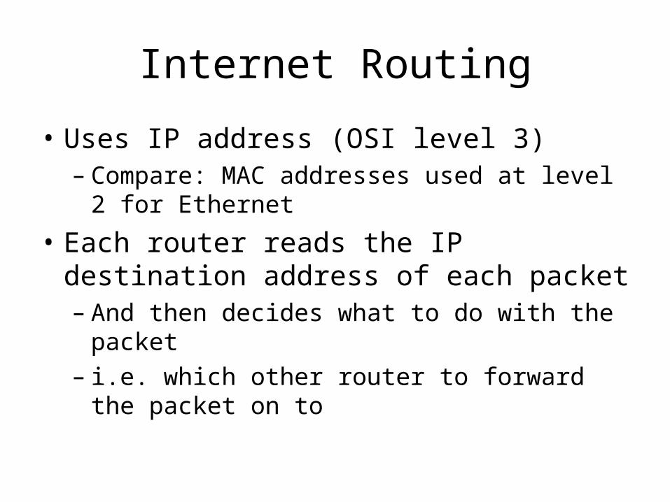
Internet Routing
• Uses IP address (OSI level 3)– Compare: MAC addresses used at level 2 for
Ethernet
• Each router reads the IP destination address of each packet– And then decides what to do with the packet– i.e. which other router to forward the packet
on to
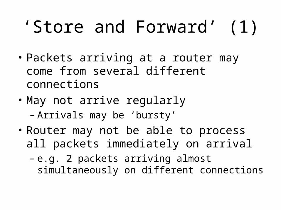
‘Store and Forward’ (1)
• Packets arriving at a router may come from several different connections
• May not arrive regularly– Arrivals may be ‘bursty’
• Router may not be able to process all packets immediately on arrival– e.g. 2 packets arriving almost simultaneously
on different connections
‘Store and Forward’ (2)
• As packets arrive, they are added to a “buffer”– area of memory where packets are stored
temporarily until they can be processed
• Packets are processed in order of arrival– ‘first in, first out’ (FIFO) stack
• Note: if the buffer gets full, further packets are discarded and lost
Routing decisions
• Router uses the destination IP address in the packet IP header to decide what to do with the packet– Maybe send to a local network to which the
router is connected• router must know the IP addresses relevant to its
own local network(s)
– Maybe forward on to another router• But which one?
Routing tables
• Each router has a database of IP addresses (or starts of IP addresses)
• For each IP address, there is a link that a packet for that IP address should be forwarded on
• Router reads the destination IP address, consults the routing table, and forwards the packet on the appropriate link
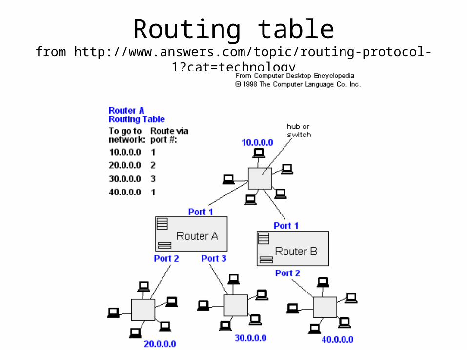
Routing tablefrom http://www.answers.com/topic/routing-protocol-1?cat=technology
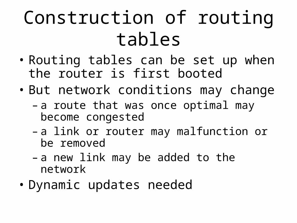
Construction of routing tables
• Routing tables can be set up when the router is first booted
• But network conditions may change– a route that was once optimal may become
congested– a link or router may malfunction or be
removed– a new link may be added to the network
• Dynamic updates needed
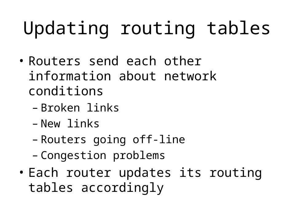
Updating routing tables
• Routers send each other information about network conditions– Broken links– New links– Routers going off-line– Congestion problems
• Each router updates its routing tables accordingly
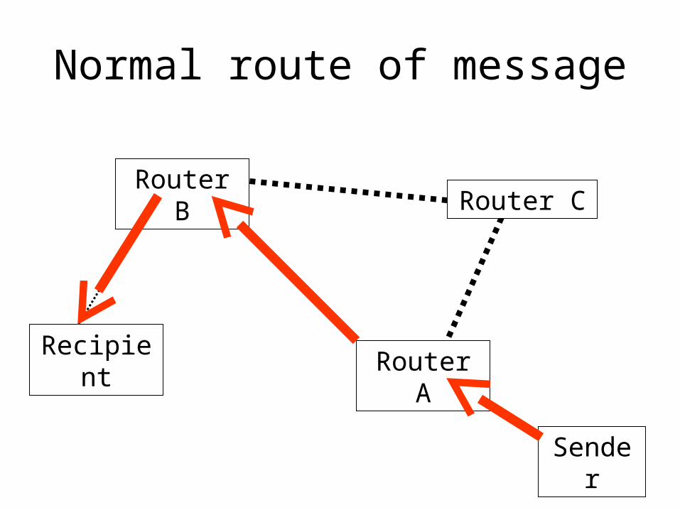
Normal route of message
Recipient
Router BRouter C
Router A
Sender
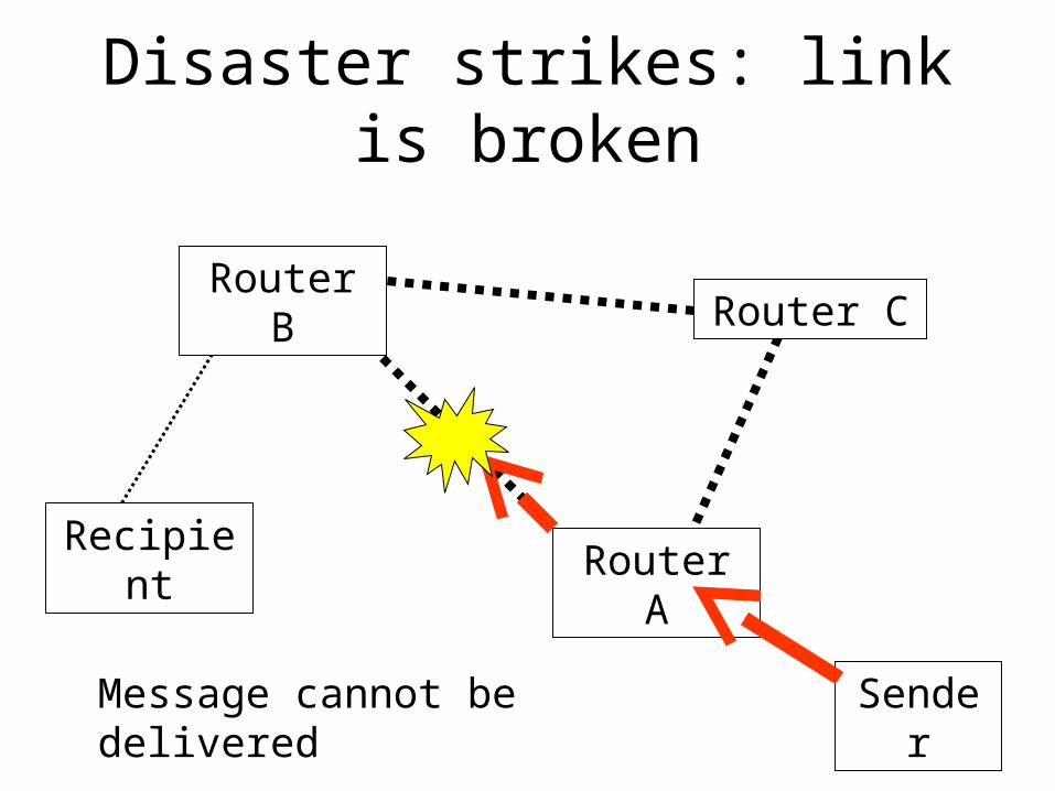
Disaster strikes: link is broken
Recipient
Router BRouter C
Router A
SenderMessage cannot be delivered
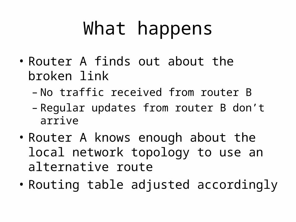
What happens
• Router A finds out about the broken link– No traffic received from router B– Regular updates from router B don’t arrive
• Router A knows enough about the local network topology to use an alternative route
• Routing table adjusted accordingly
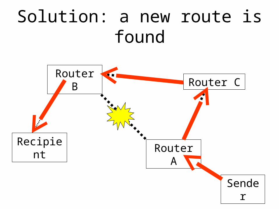
Solution: a new route is found
Recipient
Router BRouter C
Router A
Sender
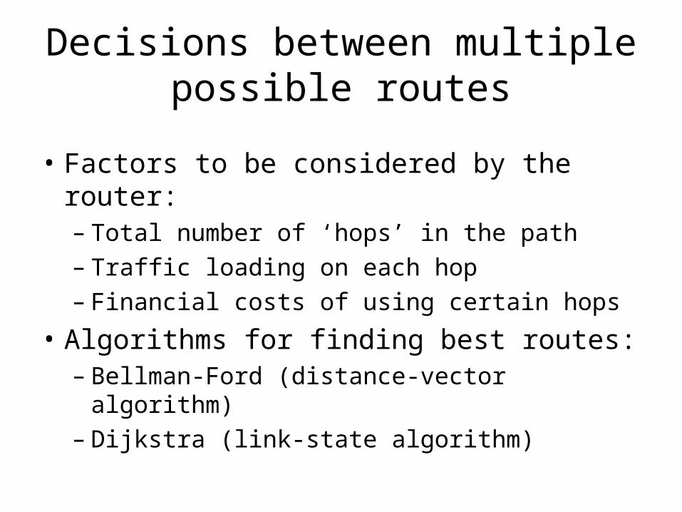
Decisions between multiple possible routes
• Factors to be considered by the router:– Total number of ‘hops’ in the path– Traffic loading on each hop– Financial costs of using certain hops
• Algorithms for finding best routes:– Bellman-Ford (distance-vector algorithm)– Dijkstra (link-state algorithm)
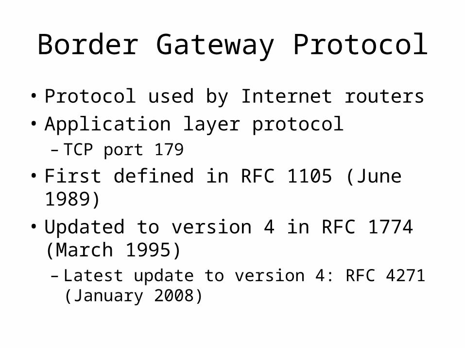
Border Gateway Protocol
• Protocol used by Internet routers
• Application layer protocol– TCP port 179
• First defined in RFC 1105 (June 1989)
• Updated to version 4 in RFC 1774 (March 1995)– Latest update to version 4: RFC 4271
(January 2008)

End