comp2121 avr board setup experiment - computer …cs2121/labs/avrdevboard_2012.pdf · comp2121 avr...
TRANSCRIPT
COMP2121 AVR Board Setup Experiment
1. Objectives
In this lab, you will learn AVR programming on • AVR development board
2. Preparation
Before coming to the laboratory, you should: • Read through the document available upon selecting Board Notes from the left menu at the course page for a general description of the AVR development board and for the system set up; and, • Read through the introduction in the next section and complete the tutorial task.
3. Introduction to AVR Microprocessor Development Board This section gives you a tutorial-like introduction to the AVR Microcontroller Development Board and how to use it. In the subsequent tasks you will use the development board to run your program instead of only simulating it using AVR Studio.
3.1. Equipment Handling Precautions A few precautions are necessary in the Digital System Laboratory: • The Laboratory is an environment where, unfortunately, it is quite easy for you to build up a static electric charge. Electrostatic discharge can destroy electronic equipment, including the circuits used in this Laboratory, without giving any sign of doing so! • Since you may be carrying a static charge without even realizing it, you should always discharge yourself. You can do this painlessly by touching a grounded conductor using a coin, a key or another metallic object instead of your finger. You can use one of the oscillator input connectors as a suitable grounded conductor. • Short circuits may damage certain devices. Please remove any metal watchstraps, buckles, rings and so on before handling the boards. There are no dangerous voltages or currents that will harm you here, but this is a good habit to always act with caution and follow the designed procedure. • Always turn the power off before connecting or disconnecting any I/O subsystems.
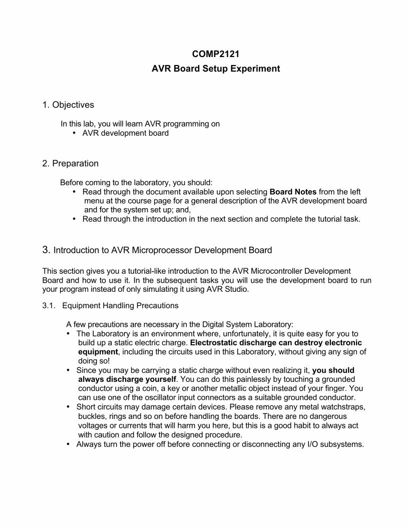
3.2. Examining the AVR Microcontroller Board
Figure 1: AVR Development Board
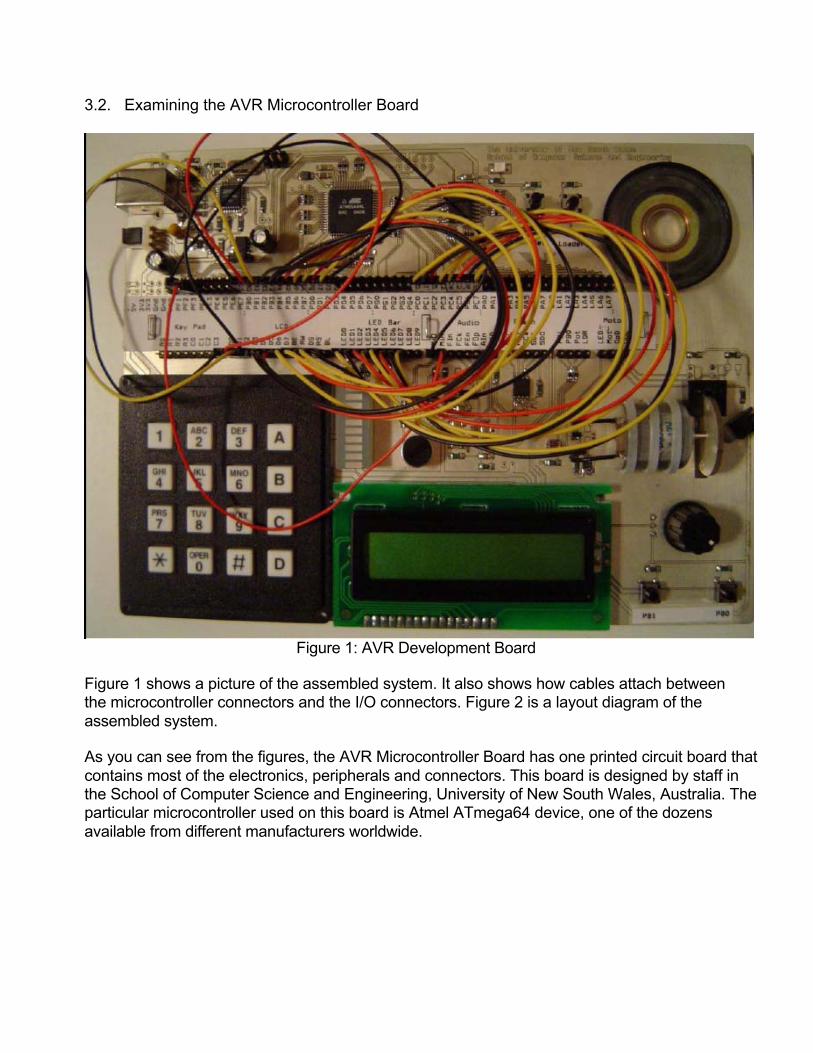
Figure 1 shows a picture of the assembled system. It also shows how cables attach between the microcontroller connectors and the I/O connectors. Figure 2 is a layout diagram of the assembled system.
As you can see from the figures, the AVR Microcontroller Board has one printed circuit board that contains most of the electronics, peripherals and connectors. This board is designed by staff in the School of Computer Science and Engineering, University of New South Wales, Australia. The particular microcontroller used on this board is Atmel ATmega64 device, one of the dozens available from different manufacturers worldwide.
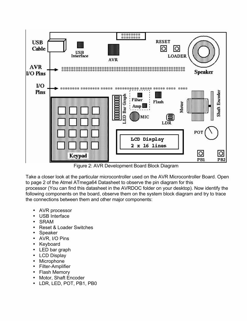
Figure 2: AVR Development Board Block Diagram
Take a closer look at the particular microcontroller used on the AVR Microcontroller Board. Open to page 2 of the Atmel ATmega64 Datasheet to observe the pin diagram for this processor (You can find this datasheet in the AVRDOC folder on your desktop). Now identify the following components on the board, observe them on the system block diagram and try to trace the connections between them and other major components:
• AVR processor • USB Interface • SRAM • Reset & Loader Switches • Speaker • AVR, I/O Pins • Keyboard • LED bar graph • LCD Display • Microphone • Filter-Amplifier • Flash Memory • Motor, Shaft Encoder • LDR, LED, POT, PB1, PB0
; led.asm ; Author: ; Date:
.include "m64def.inc"
.def temp =r16 .equ PATTERN1 = 0x5B .equ PATTERN2 = 0xAA
ser temp out PORTC, temp out DDRC, temp out PORTA, temp clr temp out DDRA, temp
switch0: sbic PINA, 0
rjmp switch1 ldi temp, PATTERN1 out PORTC, temp
switch1: sbic PINA, 1
rjmp switch0 ldi temp, PATTERN2 out PORTC, temp rjmp switch0
; Write ones to all the LEDs ; PORTC is output
; Enable pull-up resistors on PORTA ;
PORTA is input
; Skip the next instruction ; if switch0 is pushed ; If not pushed, check the other switch ; Store PATTERN1 to the LEDs ; if the switch was pushed
; Skip the next instruction ; if switch 1 is pushed ; If not pushed, check the other switch ; Store PATTERN2 to the LEDs ; if the switch was pushed ; Now check switch 1 again
Figure 3: Program led.asm In AVR Studio, create a new file and call it led.asm. Enter the code in Figure 3 and compile it. You are now ready to advance to the next step, which is running the code in simulator mode. 3.3. Simulating the Code At this point you have generated the files needed to simulate the code. To start running the code, select “I/O” tab at the bottom of “Workspace” window. Now double click on “I/O ATMEGA64” tree, or press the “+” next to “I/O ATMEGA64” to expand it. This is used to inspect and modify the contents of the I/O registers in the execution target. The standard configuration gives you a quick overview of the hardware with the ability to expand particular items for more information. Expand PORTC tree in the list. It shows all registers associated with Port C, these are: Port C Data Register (PORTC), Data Direction (DDRC) and Input Pins (PINC).
• PORTC: PORTC register is a read/write register. It is initialized at reset to $00. When programmed as an output, then writing to PORTC will allow you to change the logic state at the PORTC pins. • DDRC: The register is used to control the direction of each of the pins of the PORTC. Writing a “0” (which is also the reset value) in any bit of this register will make the corresponding PORTC bit as input, and writing a “1” will make it an output bit. • PINC: This is a read-only port, and with this you can read the logic at the physical pin of PORTC.
As shown, each bit in the registers is represented by a white square box. A logical zero (0) is represented by a white square box and a logical one (1) is represented by a black square box. These boxes will be updated during program execution, and show the current state of every bit. You may also set and clear these bits by clicking on the appropriate box at any time during the program execution. Now single step down to the last line of the code by repeated pressing the F11 key or by selecting “Step Into” from the “Debug” menu. Notice how the color changes from black to red on the registers that change value. This makes it easier to identify which registers change value on each instruction. Continue pressing the F11 key and see how the binary value in PORT C is changed. 3.4. Download When we have finished simulating the program, we need to download the program to the hardware and run it there. An “Intel Hex Format” file called led.hex has been generated after “Build and Run”. Here are some of the steps you might need to follow: (Note: Don’t have the USB power cable plugged in before performing any wiring)
1. Use the provided patch cables to connect pins PC0-PC7 to the LED0-LED7, and PB0- PB1 to the PA0-PA1. (make sure you have the right order). 2. Plug the USB cable into the board and the PC. 3. Open the downloader nite by double clicking the nite icon on the desktop. 4. Hold the Loader push-button down on the AVR Microcontroller Board. 5. While holding the Loader push-button down push the Reset button and release the Reset button. 6. Release the loader button. The board is now waiting for a program to be downloaded. 7. When you see the logo in the nite window appears, then you can download the new version of the program. 8. Now change the directory by typing :path directory name (ie: :path led). 9. To download the program, type :send file.hex (ie: :send led.hex). This downloads the program to the AVR board, and some output is also generated. 10. Press the Reset switch to execute the program.
Note: every time you are downloading a new or modified program to the AVR Microcontroller Board, you have to RESET the board and repeat steps 4-6.
Now work out the bit patterns. Does a 1 bit turn the LED on or does it turn it off? Which registers change their value? How are the values been changed? Which instruction turns on the LEDs? Run and test the program.