compact hydraulic power packs usma 05 - argo- · pdf fileforms the base of the power pack, ......
TRANSCRIPT

1
Functional Description
Each power pack consists of an electric motor, a pump,a manifold and a tank. The aluminum Die-cast Bodyforms the base of the power pack, on which all the maincomponents, including the hydraulic elements, aremounted. The function of the power packs is apparentfrom the respective hydraulic circuit diagrams. Thedesired combination of particular components andhydraulic elements can be defined by reference to theordering code and the respective tables. The lay-out ofadditional circuits is defined by an application numberwhich determines the manufacturer.The hydraulic circuits can be accomplished in sizes 03,04 and 06. The size 03 is in a form of sectional directionalvalves.
The mounting position of the power pack is eitherhorizontal or vertical - see the Power Pack Dimensionson pages 10 to 15. All ports have 9/16-18 UNF SAEJ1926-1 internal threads.With the standard model the connecting ports A, B of thecomponents of the vertical stacking assembly areoriented onto one side. Orientation of ports A, B eachonto another side is to be agreed with the manufacturer.The basic combinations of electric motors and pumps,as well as their code designations, are shown in tables 1,2 and 3.Information regarding the basic power pack surfacetreatment is on page 3.
� Compact Hydraulic Power Packs for use in Lift- platforms, Lift-tables, Ramps, Presses,Machine Tools, Mobile and other applications
� 3 basic hydraulic circuits integrated in the Die-cast Adapter Block, others per request,also optional double pumps
� Additional circuits can be added in form of manifolds or standard vertical or horizontalstack assemblies
� Usable Reservoir capacities from 0.4 to10.3 Gallon, 1.5 to 39 liter, made of Plasticor Alum.-diecastings. Custom Reservoirs per request.
� Gear pumps with low noise levels
HU 721012/2012
pmax • 3600 PSI (250 bar) • 4.5 GPM (17 L/min)
Compact Hydraulic Power Packs USMA 05Replaces
HA 7211 6/2008

2
HU 7210
Ordering Code
Code of the electric motor(see tables 1, 2 and 3)
Pump displacementin cm3
Series P0.049 (0.8) 080.073 (1.2) 120.098 (1.6) 160.128 (2.1) 210.153 (2.5) 250.201 (3.3) 330.220 (3.6) 360.269 (4.4) 440.293 (4.8) 480.354 (5.8) 580.378 (6.2) 620.482 (7.9) 79
Compact Power-Pack
Solenoid voltage0120002400
12V DC24V DC
12060 120V / 50 (60)HzOther voltages per request -
consult factory
DC electric motorwith Starter Switch R
Single-phase electric motorwithout starting modulewith starting module
0M
3-phase electric motor 0
Foot bracket0 without foot bracketF low foot bracket
Type of filter used0 without filterS suction filterR* return line filter without indicationE* return line filter with el. indicationM* return line filter with manometer
* for tank codes 71 - 74 onlyTank codesee pages 10 - 15
Type of hydraulic circuitsee table on pages 7
Type of stacking assembly0 without stacking assemblyBCDEF
Configuration BConfiguration CConfiguration DConfiguration EConfiguration F
(see page 11)
USMA 05- / . - - . / -
Number of add-on units0 without stacking assembly12345
1Section2 Sections3 Sections4 Sections5 Sections
(see page 11)
Nominal size of stackingassembly elements
0 Without stacking assembly346
Size 03Size D02 (04)Size D03 (06)(see page 11)
3
HU 7210
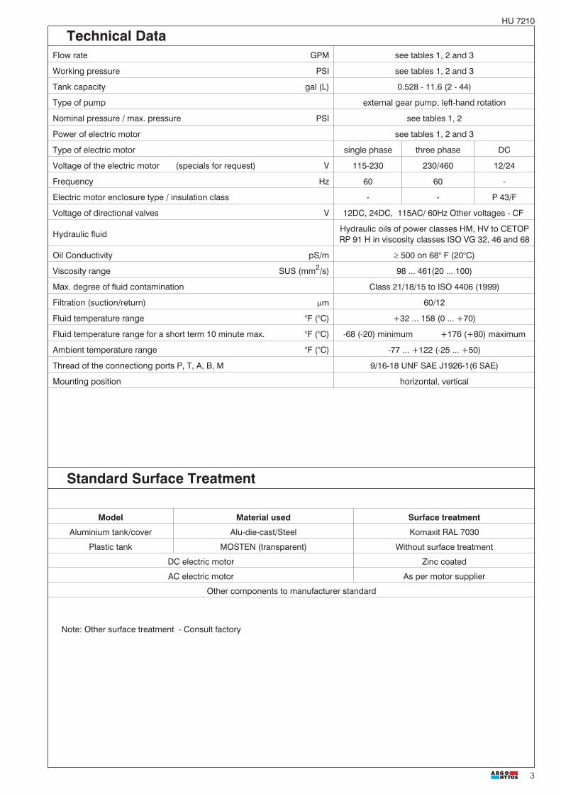
Standard Surface Treatment
Flow rate GPM see tables 1, 2 and 3
Working pressure PSI see tables 1, 2 and 3
Tank capacity gal (L) 0.528 - 11.6 (2 - 44)
Type of pump external gear pump, left-hand rotation
Nominal pressure / max. pressure PSI see tables 1, 2
Power of electric motor see tables 1, 2 and 3
Type of electric motor single phase three phase DC
Voltage of the electric motor (specials for request) V 115-230 230/460 12/24
Frequency Hz 60 60 -
Electric motor enclosure type / insulation class - - P 43/F
Voltage of directional valves V 12DC, 24DC, 115AC/ 60Hz Other voltages - CF
Hydraulic fluidHydraulic oils of power classes HM, HV to CETOPRP 91 H in viscosity classes ISO VG 32, 46 and 68
Oil Conductivity pS/m � 500 on 68° F (20°C)
Viscosity range SUS (mm2/s) 98 ... 461(20 ... 100)
Max. degree of fluid contamination Class 21/18/15 to ISO 4406 (1999)
Filtration (suction/return) �m 60/12
Fluid temperature range °F (°C) +32 ... 158 (0 ... +70)
Fluid temperature range for a short term 10 minute max. °F (°C) -68 (-20) minimum +176 (+80) maximum
Ambient temperature range °F (°C) -77 ... +122 (-25 ... +50)
Thread of the connectiong ports P, T, A, B, M 9/16-18 UNF SAE J1926-1(6 SAE)
Mounting position horizontal, vertical
Note: Other surface treatment - Consult factory
Model Material used Surface treatment
Aluminium tank/cover Alu-die-cast/Steel Komaxit RAL 7030
Plastic tank MOSTEN (transparent) Without surface treatment
DC electric motor Zinc coated
AC electric motor As per motor supplier
Other components to manufacturer standard
Technical Data

4
HU 7210
Table 1a Three-phase motor
* pn. - nominal pressure = the highest working pressure allowed without time restriction** pmax. - maximum pressure = maximum pressure allowed for a short time - max. 20s
Code of theelectric motor
Code of the pump
36 P2-... 44 P2-... 48 P2-... 58 P2-... 62 P2-... 79 P2-...
pmax. ** [PSI] 3626 2901 2320
460V n[R.P.M.] p[HP] Q/pn.* [GPM] / [PSI]
9
1725
1/4
10 1/3
11 1/2 1.6 435 1.9 363
12 3/4 1.6 667 1.9 551 2.1 493 2.5 406 2.7 392
13 1 1.6 885 1.9 725 2.1 667 2.5 551 2.7 508 3.4 406
14 11/2 1.6 1320 1.9 1088 2.1 1001 2.5 827 2.7 769 3.4 609
15 2 1.6 1769 1.9 1450 2.1 1334 2.5 1102 2.7 1030 3.4 812
16 3 1.6 2654 1.9 2176 2.1 2002 2.5 1653 2.7 1537 3.4 1218
17 5 2.1 2901 2.5 2741 2.7 2567 3.4 2016
25
3450
1/3
26 1/2
27 3/4 3.1 334
28 1 3.1 435 3.8 363 4.2 334
29 11/2 3.1 667 3.8 551 4.2 493
30 2 3.1 885 3.8 725 4.2 667
31 3 3.1 1320 3.8 1088 4.2 1001
32 5 3.1 2205 3.8 1813 4.2 1668
Code of theelectric motor
Code of the pump
08 P2-... 12 P2-... 16 P2-... 21 P2-... 25 P2-... 33 P2-...
pmax. ** [PSI] 3626
460V n[R.P.M.] p[HP] Q/pn.* [GPM] / [PSI]
9
1725
1/4 0.4 928 0.6 638 0.7 479 0.9 377
10 1/3 0.4 1233 0.6 841 0.7 638 0.9 508 1.1 421
11 1/2 0.4 1857 0.6 1262 0.7 957 0.9 769 1.1 638 1.4 479
12 3/4 0.4 2785 0.6 1900 0.7 1436 0.9 1146 1.1 957 1.4 725
13 1 0.6 2524 0.7 1915 0.9 1523 1.1 1276 1.4 957
14 11/2 0.7 2886 0.9 2292 1.1 1900 1.4 1436
15 2 0.9 2901 1.1 2538 1.4 1914
16 3 1.4 2886
17 5
25
3450
1/3 0.7 624 1.1 421
26 1/2 0.7 928 1.1 638 1.4 479 1.8 377
27 3/4 0.7 1392 1.1 943 1.4 725 1.8 566 2.2 479 2.9 363
28 1 0.7 1857 1.1 1262 1.4 957 1.8 769 2.2 638 2.9 479
29 11/2 0.7 2785 1.1 1900 1.4 1436 1.8 1146 2.2 957 2.9 725
30 2 1.1 2524 1.4 1914 1.8 1523 2.2 1276 2.9 957
31 3 1.8 2292 2.2 1900 2.9 1436
32 5 2.2 2901 2.9 2393
Table 1b

5
HU 7210
12V 24V HP (kW) Code of the pump 40 - 63Code of the electric motor Q GPM (L/min) /p PSI (bar)
45 / 1 (0.70)
See characteristics on page 6
44 1 (0.80)/ 46 11/2 (1.20)
51 / 2 (1.50)/ 52 21/2 (2.00)/ 63 4 (3.00)
Table 3
* pn. - nominal pressure = the highest working pressure allowed without time restriction** pmax. - maximum pressure = maximum pressure allowed for a short time - max. 20s
Code of theelectric motor
Code of the pump
36 P2-... 44 P2-... 48 P2-... 58 P2-... 62 P2-... 79 P2-...pmax. ** [PSI] 3626 2901 2320
230V n[R.P.M.] p[HP] Q/pn.* [GPM] / [PSI]
1
1725
1/4
2 1/3 1.6 290 1.9 247
3 1/2 1.6 435 1.9 363 2.1 334 2.5 276 2.7 261
4 3/4 1.6 667 1.9 551 2.1 493 2.5 406 2.7 392 3.4 305
5 1 1.6 885 1.9 725 2.1 667 2.5 551 2.7 508 3.4 406
6 11/2 1.6 1320 1.9 1088 2.1 1001 2.5 827 2.7 769 3.4 609
7 2 1.6 1770 1.9 1450 2.1 1334 2.5 1102 2.7 1030 3.4 812
8 3 1.9 2176 2.1 2002 2.5 1653 2.7 1537 3.4 1218
18
3450
1/3
19 1/2
20 3/4 3.1 334 3.8 276
21 1 3.1 435 3.8 363 4.2 334
22 11/2 3.1 667 3.8 551 4.2 493
23 2 3.1 885 3.8 725 4.2 667
24 3 3.1 1320 3.8 1088 4.2 1001
Table 2a Single phase motor
Table 2b
Attention! The DC motors must be loaded, so as to reduce the revolutions! Do not run the motors without pressure loading!
Code of theelectric motor
Code of the pump
08 P2-... 12 P2-... 16 P2-... 21 P2-... 25 P2-... 33 P2-...pmax. ** [PSI] 3626
230V n[R.P.M.] p[HP] Q/pn.* [GPM] / [PSI]
1
1725
1/4 0.4 928 0.6 638 0.7 479 0.9 377 1.1 319
2 1/3 0.4 1233 0.6 841 0.7 638 0.9 508 1.1 421 1.4 319
3 1/2 0.4 1857 0.6 1262 0.7 957 0.9 769 1.1 638 1.4 479
4 3/4 0.6 1900 0.7 1436 0.9 1146 1.1 957 1.4 725
5 1 0.7 1915 0.9 1523 1.1 1276 1.4 957
6 11/2 0.9 2901 1.1 1900 1.4 1436
7 2 1.4 1914
8 3
18
3450
1/3 0.7 624 1.1 421 1.4 319 1.8 261
19 1/2 0.7 928 1.1 638 1.4 479 1.8 377 2.2 319
20 3/4 0.7 1392 1.1 943 1.4 725 1.8 566 2.2 479 2.9 363
21 1 0.7 1857 1.1 1262 1.4 957 1.8 769 2.2 638 2.9 479
22 11/2 0.7 2785 1.1 1900 1.4 1436 1.8 1146 2.2 957 2.9 725
23 2 1.1 2524 1.4 1914 1.8 1523 2.2 1276 2.9 957
24 3 1.4 2886 1.8 2901 2.2 1900 2.9 1436

6
HU 7210
Characteristics
( )2
( )4
( )6
( )8
( )10
( )12
0
( )50 ( )100 ( )150 ( )200
03
0506
12
16
25
33E-motor12V 0,7kW
08121621
33
4448
E-motor24V 1,2kW
36
62
12
21
33
44
58 E-motor12V 1,5kW
36
12162125
44
58
E-motor24V 2kW
36
79
62
2125
44
58
E-motor24V 3kW
36
79
03
06
12
1621
25
33E-motor24V 0,8kW
62
48
33
21
08
04
08
0504
16
25
4858
25
33
48
3.2
2.6
2.1
1.6
1.1
0.5
(3)
(6)
(9)
(12)
(15)
(18) 4.8
4.0
3.2
2.4
1.6
0.8
(4)
(8)
(12)
(16)
(20)
(24) 6.3
5.3
4.2
3.2
2.1
1.1
730 1450 2180 2900
0
( )50 ( )100 ( )150 ( )200
730 1450 2180 2900
0
( )50 ( )100 ( )150 ( )200
730 1450 2180 2900 0
( )50 ( )100 ( )150 ( )200
730 1450 2180 2900
0
( )50 ( )100 ( )150 ( )200
730 1450 2180 2900
0
( )50 ( )100 ( )150 ( )200
730 1450 2180 2900
( )2
( )4
( )6
( )8
( )10
( )12 3.2
2.6
2.1
1.6
1.1
0.5
(3)
(6)
(9)
(12)
(15)
(18) 4.8
4.0
3.2
2.4
1.6
0.8
(4)
(8)
(12)
(16)
(20)
(24) 6.3
5.3
4.2
3.2
2.1
1.1
Pressure p [PSI (bar)]
Pressure p [PSI (bar)]
Pressure p [PSI (bar)] Pressure p [PSI (bar)]
Pressure p [PSI (bar)]
Pressure p [PSI (bar)]
Flow
Q [G
PM (l
/min
)]
Flow
Q [G
PM (l
/min
)]
Flow
Q [G
PM (l
/min
)]
Flow
Q [G
PM (l
/min
)]
Flow
Q [G
PM (l
/min
)]
Flow
Q [G
PM (l
/min
)]
Code 45
Code 46 Code 51
Code 44
Code 63Code 52

7
HU 7210
2.72 69( )
2.89
73,5
()
2.68
68()
M
P T
M
Z
W
M
T P
Z W
2.83(72)
X
M
Y
PTP T
M
2.40 61( )2.68( )68
2.89
73,5
()
2.68
68()
Y
X
M
Z
W
Z W
2.79(71)
YX
X
Y
M
P
M
M
P
2.63
(67)
3.98(101) 3.21(81,5)
2.89
(73,
5)
Z
L
LZ
100
4
Type Ordering No. Symbols
M Starting module 736-2801
0 Plug VSTI G1/4 336 350 000 014
Exact position of the starting module or plug ... ref. page 18 .
Mounted on the side of the pump via thread G1/4
Y
X
Mounted on the side of the pump via thread G1/4
A
CXY
EXY
Basic Hydraulic Circuit Diagrams
3.94(100)
0.16(4)

8
HU 7210
2.83(72)
6.89
(175
)
4.01(102)
0.20(5)
2.76(70)
5SD1M1-A2/SL3
+ lever with micro switch
4SD1M1-A2/SL2
+lever without micro switch
2 SD3E-A2/H2O2
1 SD3E-A2/H2L2
3 SD1M-A2/SL1
0 336312341602
X Type of valve Functional symbolX
2.28(8)
0.33(8,5)
1.18(30)max
0.20(5)
Y
1 VSV1-UNF
0 336 312 341 602 pro X = 0
Y Type of throttle valve Functional symbol
Manually controlled pump – upon request
0 531-0602 pro X = 0
2 SF22A-A2/H*
Z Pilot Operated Pressure Relief Valve SR1A-A2/S - Pressure range see data sheet HU 5063
W Check Valves SC1F-A3/C
L Logical valve SSH1H-A3/C
* The size of the throttle valve corresponds regularly with the flow rateQ of the pump used.Other throttle valve size on request of the customer.
9
HU 7210
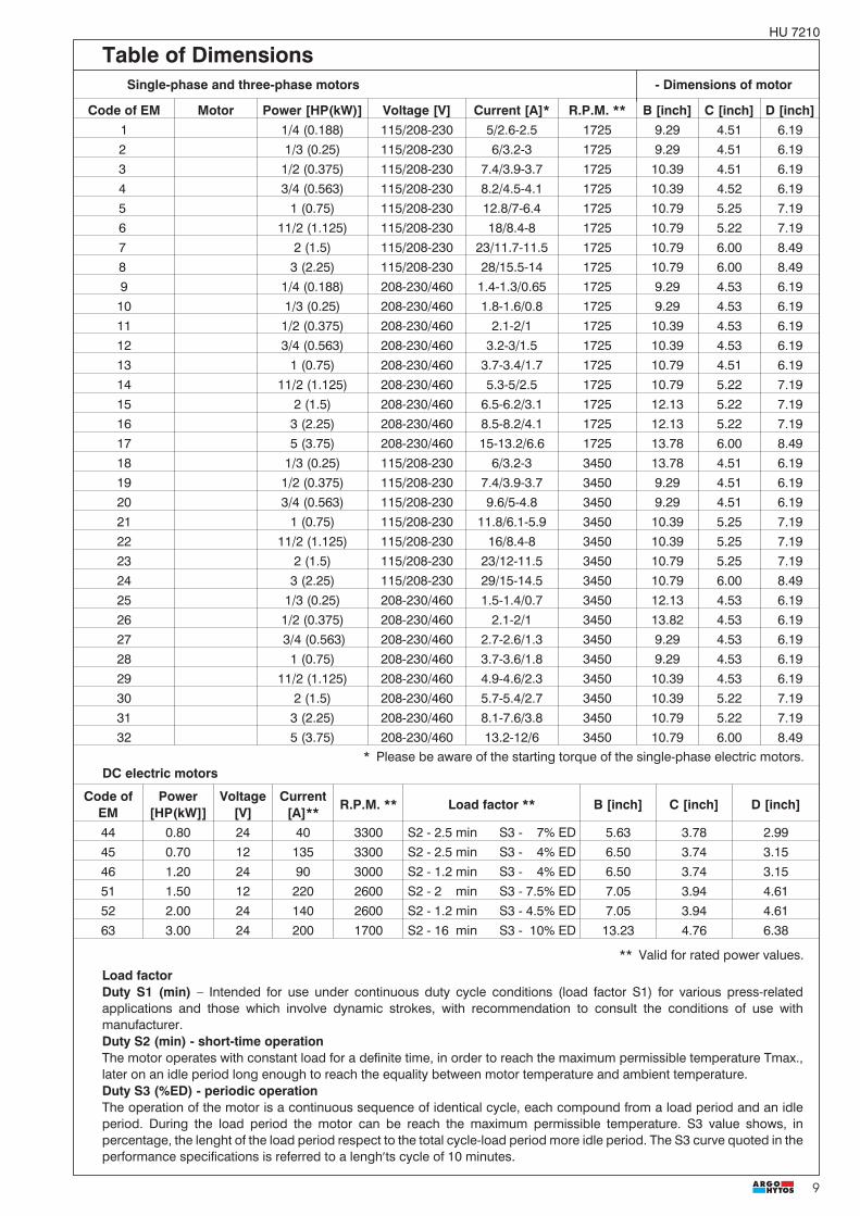
Table of DimensionsSingle-phase and three-phase motors - Dimensions of motor
Code of EM Motor Power [HP(kW)] Voltage [V] Current [A]* R.P.M. ** B [inch] C [inch] D [inch]1 1/4 (0.188) 115/208-230 5/2.6-2.5 1725 9.29 4.51 6.192 1/3 (0.25) 115/208-230 6/3.2-3 1725 9.29 4.51 6.193 1/2 (0.375) 115/208-230 7.4/3.9-3.7 1725 10.39 4.51 6.194 3/4 (0.563) 115/208-230 8.2/4.5-4.1 1725 10.39 4.52 6.195 1 (0.75) 115/208-230 12.8/7-6.4 1725 10.79 5.25 7.196 11/2 (1.125) 115/208-230 18/8.4-8 1725 10.79 5.22 7.197 2 (1.5) 115/208-230 23/11.7-11.5 1725 10.79 6.00 8.498 3 (2.25) 115/208-230 28/15.5-14 1725 10.79 6.00 8.499 1/4 (0.188) 208-230/460 1.4-1.3/0.65 1725 9.29 4.53 6.1910 1/3 (0.25) 208-230/460 1.8-1.6/0.8 1725 9.29 4.53 6.1911 1/2 (0.375) 208-230/460 2.1-2/1 1725 10.39 4.53 6.1912 3/4 (0.563) 208-230/460 3.2-3/1.5 1725 10.39 4.53 6.1913 1 (0.75) 208-230/460 3.7-3.4/1.7 1725 10.79 4.51 6.1914 11/2 (1.125) 208-230/460 5.3-5/2.5 1725 10.79 5.22 7.1915 2 (1.5) 208-230/460 6.5-6.2/3.1 1725 12.13 5.22 7.1916 3 (2.25) 208-230/460 8.5-8.2/4.1 1725 12.13 5.22 7.1917 5 (3.75) 208-230/460 15-13.2/6.6 1725 13.78 6.00 8.4918 1/3 (0.25) 115/208-230 6/3.2-3 3450 13.78 4.51 6.1919 1/2 (0.375) 115/208-230 7.4/3.9-3.7 3450 9.29 4.51 6.1920 3/4 (0.563) 115/208-230 9.6/5-4.8 3450 9.29 4.51 6.1921 1 (0.75) 115/208-230 11.8/6.1-5.9 3450 10.39 5.25 7.1922 11/2 (1.125) 115/208-230 16/8.4-8 3450 10.39 5.25 7.1923 2 (1.5) 115/208-230 23/12-11.5 3450 10.79 5.25 7.1924 3 (2.25) 115/208-230 29/15-14.5 3450 10.79 6.00 8.4925 1/3 (0.25) 208-230/460 1.5-1.4/0.7 3450 12.13 4.53 6.1926 1/2 (0.375) 208-230/460 2.1-2/1 3450 13.82 4.53 6.1927 3/4 (0.563) 208-230/460 2.7-2.6/1.3 3450 9.29 4.53 6.1928 1 (0.75) 208-230/460 3.7-3.6/1.8 3450 9.29 4.53 6.1929 11/2 (1.125) 208-230/460 4.9-4.6/2.3 3450 10.39 4.53 6.1930 2 (1.5) 208-230/460 5.7-5.4/2.7 3450 10.39 5.22 7.1931 3 (2.25) 208-230/460 8.1-7.6/3.8 3450 10.79 5.22 7.1932 5 (3.75) 208-230/460 13.2-12/6 3450 10.79 6.00 8.49
* Please be aware of the starting torque of the single-phase electric motors.DC electric motors
Code ofEM
Power[HP(kW]]
Voltage[V]
Current[A]**
R.P.M. ** Load factor ** B [inch] C [inch] D [inch]
44 0.80 24 40 3300 S2 - 2.5 min S3 - 7% ED 5.63 3.78 2.9945 0.70 12 135 3300 S2 - 2.5 min S3 - 4% ED 6.50 3.74 3.1546 1.20 24 90 3000 S2 - 1.2 min S3 - 4% ED 6.50 3.74 3.1551 1.50 12 220 2600 S2 - 2 min S3 - 7.5% ED 7.05 3.94 4.6152 2.00 24 140 2600 S2 - 1.2 min S3 - 4.5% ED 7.05 3.94 4.6163 3.00 24 200 1700 S2 - 16 min S3 - 10% ED 13.23 4.76 6.38
Load factorDuty S1 (min) – Intended for use under continuous duty cycle conditions (load factor S1) for various press-relatedapplications and those which involve dynamic strokes, with recommendation to consult the conditions of use withmanufacturer.Duty S2 (min) - short-time operationThe motor operates with constant load for a definite time, in order to reach the maximum permissible temperature Tmax.,later on an idle period long enough to reach the equality between motor temperature and ambient temperature.Duty S3 (%ED) - periodic operationThe operation of the motor is a continuous sequence of identical cycle, each compound from a load period and an idleperiod. During the load period the motor can be reach the maximum permissible temperature. S3 value shows, inpercentage, the lenght of the load period respect to the total cycle-load period more idle period. The S3 curve quoted in theperformance specifications is referred to a lengh�ts cycle of 10 minutes.
** Valid for rated power values.

10
HU 7210
Valve Dimensions Dimensions in inches and millimeters (in brackets)
0.47
(12)
0.47
(12)
0.41(10,5) T P
0 0.75
19()
1.42
36()
2.09
53()
2.83
72()
4 x M8 DEPTH 16
1.61(41) 1.61(41)
2 x 3/8-16 UNC DEPTH
0.79
(20)
Connecting Block Connection bracket
Code of the tank Capacity in US gal [L] Working volume US gal [L] A E62 0.528 (2) 0.449 (1.7) 6.850 (174) -64 1.056 (4) 0.792 (3.0) 10.669 (271) 11066 1.585 (6) 1.188 (4.5) 14.213 (361) 15568 2.113 (8) 1.585 (6.0) 17.756 (451) 20070 2.641(10) 1.981 (7.5) 21.299 (541) 245
E
TP
1.56 BA
2.78
(70.
6)5.
57(1
41.5
)
6.69
170
()
2.89
(73.
5)
1.57(40)
E
(39.5)
D
M
P
S
6.30
(60)
0.47(12)
S
Thread of the connecting portsP, T, M - 9/16-18 UNFSAE J1926-1(-6 SAE)
For AC Power units the mounting bracket is suitable for motors up tu 2PH only Please use for larger motors the feetof the electric motor.
Power pack with plastic tank - mouting position horizontal
Lay - out of the Block
S P
Power pack foot bracket
TypDimensionsL [Inch(mm)]
F 1.46 (37)Part No. 23475600
L0.
16(4
)
5.91/5.90 (150 0,2)�
6.89(175)
3.44(87,5)
0.49(12,5)
0.49
1.83
(46,
5)3.
23(8
2)
6x�0.41
6.89
(175
)
5.91
/5.9
0 (1
500,
2)�
(12,
5)
(�10,5)
3.94
(100
)
0.65(16,5)0.22(5,5)R0.14(R3,5)
TANK SUPPORTcode 64-70 with footbracket of Power PackConfiguration F
TANK SUPPORTcode 64-70
Part No. 23479000
withFoot
withoutFoot

11
HU 7210
Configurations of stackingValve Dimensions Dimensions in inches and millimeters (in brackets)
Configuration DSize 03
Thread of the connecting ports A, B, P, T, M - 9/16-18 UNF SAE J1926-1(-6SAE)
Configuration B
FFFFF
1,69(43)
4.09
(104
)
2.17
(55)
EG
1.08(27,5)
1.73
(44)
FF
FF
F
2.17(55)G E
1.22 (31)
1.22 (31)
1.22 (31)
1.22 (31)
0.98 (25)
0.98 (25)
2.21(56)
3.23(82)
EG
1.18
(30)
1.22(31)
1.22(31)
1.22(31)
1.22(31)
0.98(25)
1.69(43)
4.09
(104
)
2.21
(56)
3.23
(82)
1.81(46)
FIRST - ANGLEPROJECTION
Configuration ESize 03
Number ofadd-on units
0 � 5
Configuration FSize D02 (04),
D03 (06)
Configuration BSize D02 (04),
D03 (06)
Configuration CSize D02 (04),
D03 (06)
Dimension E [in (mm)] F [in (mm)] G [in (mm)]Pressure
switchReducing
valvesPressure relief
valvesPilot operated check
valves cartridgeCheckValves
FlowValves
Size D02 (04) 1.38(35) 1.18(30) 1.38(35) 1.18(30) 1.18(30) 1.18(30) 1.57(40) 3.11(79)Size D03 (06) 1.69(43) 1.77(45) 1.57(40) 1.57(40) 1.24(31.4) 1.57(40) 1.97(50) 3.62(92)

12
HU 7210
Valve Dimensions Dimensions in inches and millimeters (in brackets)
Power pack with plastic tank - mounting position vertical
Code of the tank Capacity in US gal [L] Working volume US gal [L] A61 0.528 (2) 0.211 (1.3) 6.850 (174)63 1.056 (4) 0.291 (3.5) 10.669 (271)65 1.585 (6) 0.423 (5.5) 14.213 (361)67 2.113 (8)) 0.528 (7.5) 17.756 (451)69 2.641(10) 2.509 (9.5) 21.299 (541)
MAX
MIN
MIN
MAX
5.45(138,5)
6.30(160) 4.92(125)
1.55
(39,
5)B
A
�D C
TP
For AC Power units the mounting bracket is svitable for motors up tu 2HP only. Please use for larger motorsthe feet of the ectric motor.
Thread of the connecting portsP, T, M - 9/16-18 UNFSAE J1926-1(-6 SAE)
FIRST - ANGLEPROJECTION

13
HU 7210
Valve Dimensions Dimensions in inches and millimeters (in brackets)
Power pack with DC electric motor
Thread of the connecting ports P, T, M - 9/16-18 UNFSAE J1926-1(-6 SAE)
FIRST - ANGLEPROJECTION
Dimensions B, C, D see Page 9.

14
HU 7210
Valve Dimensions Dimensions in inches and millimeters (in brackets)
Power pack with die-cast aluminium tank
�D
A3
B1.
55(3
9,5)
A4
M
A6
4x t DEEP10A5
Sight glass
A1
A7
C
A2
Configuration B
Code ofthe tank
Capacity inUS gal [L]
Workingvolume
US gal [L]A1 A2 A3 A4 A5 A6 A7 t
71 (Al) 3.17 (12) 2.64 (10) 9.53(242) 12.28(312) 8.82(224) 8.86(225) 6.10(155) 4.41(112) 3.58(91) M8
72 (Al) 5.28 (20) 4.23 (16) 11.46(291) 14.53(369) 10(254) 10.63(270) 7.56(192) 4.13(105) 5.35(136) M8
73 (Al) 7.93 (30) 6.60 (25) 13.43(341) 19.33(491) 11.42(290) 12.83(326) 6.93(176) 4.53(115) 6.14(156) M10
74 (Al) 11.62 (44) 10.30 (39) 16.69(424) 20.67(525) 12.60(320) 13.43(341) 9.49(241) 4.53(115) 6.93(176) M10
Note: all units with tank code 71-74 shipped with sight glass and drain plug
Thread of the connecting ports A, B, P, T, M - 9/16-18 UNFSAE J1926-1(-6 SAE)
FIRST - ANGLEPROJECTION

15
HU 7210
Valve Dimensions Dimensions in inches and millimeters (in brackets)
Power pack with die-cast aluminium tank and horizontal stacking assembly RPEK1-03
A3
1.69
(43)
A4
A6
4x t DEEP10A5
Sight glass
A1
A7
C
A2
1.22
(31)
1.22
(31)
1.22
(31)
1.22
(31)
0.94
(24)
3.23(82)
2.21(56)
M
Configuration E
Code ofthe tank
Capacity inUS gal [L]
Workingvolume
US gal [L]A1 A2 A3 A4 A5 A6 A7 t
71 (Al) 3.17 (12) 2.64 (10) 9.53(242) 12.28(312) 8.82(224) 8.86(225) 6.10(155) 4.41(112) 3.58(91) M8
72 (Al) 5.28 (20) 4.23 (16) 11.46(291) 14.53(369) 10(254) 10.63(270) 7.56(192) 4.13(105) 5.35(136) M8
73 (Al) 7.93 (30) 6.60 (25) 13.43(341) 19.33(491) 11.42(290) 12.83(326) 6.93(176) 4.53(115) 6.14(156) M10
74 (Al) 11.62 (44) 10.30 (39) 16.69(424) 20.67(525) 12.60(320) 13.43(341) 9.49(241) 4.53(115) 6.93(176) M10
With the model RPEK1-03 of the vertical stacking assembly the connecting ports A, B, M are only provided with threads9/16-18 UNF; SAE J1926-1 (6 SAE)- orientation of ports is evident from the picture.
Note: all units with tank code 71-74 shipped with sight glass and drain plug
FIRST - ANGLEPROJECTION

16
HU 7210
USMA 05
5
3
10
8
7
9
2a4
1a1
112
66
Plug
Sta
rting
mod
ul
1b
1A
C-M
otor
1aA
C-m
otor
flang
esp
acer
1bA
C-m
otor
coup
ling
(dif.
type
s)2
DC
Mot
or2a
DC
-mot
orco
uplin
g3.
Tank
with
acce
ssor
ies
(dif.
type
s)4.
Cen
terb
lock
vers
ions
A,B
,C,D
,E5.
Pum
pfo
rDC
appl
icat
ions
-cou
plin
g2a
Pum
pfo
rAC
appl
icat
ions
-cou
plin
g1a
+1b
6.S
uctio
nfil
tera
ndpi
pe7.
Ret
urn
line
8.B
ase-
plat
efo
rdiff
eren
ttyp
esof
stac
king
asse
mbl
y9.
Cov
erpl
ate
forh
oriz
onta
lsta
ckin
g10
.S
tack
ing
asse
mbl
yva
lves
� The packing foil is recyclable.� Certified documentation is available per request.
Caution!
Subject to alteration without notice!
ARGO-HYTOS s.r.o. CZ - 543 15 VrchlabíTel.: +420-499-403111, Fax: +420-499-403421E-mail: [email protected]