compact jig for buckling of struts - main body
TRANSCRIPT


Abstract
An effective method for demonstration of buckling in classroom conditions is lacking.
The following project was undertaken to design and develop a lightweight rig to
demonstrate the fundamental principles of buckling in classroom conditions.
Initially the existing products that were used for similar purposes were researched
and their problems outlined. A list of objectives was developed that incorporated
functions that were not available in current products. Buckling theories were used to
calculate the required dimensions for the rig. Research was carried out before the
design process to decide on the most suitable materials to use. The design process
involved developing initial ideas from which the most practical ones were developed
further into the prototype design. The prototype was manufactured and tested which
outlined the problems with the original design. Following the redesign of the
prototype, final design was manufactured and tested. Results demonstrated that the
rig closely conformed to the theoretical buckling principles.
The outcome of the project was a success as it fulfilled all the required objectives set
and provided an accurate visual representation of buckling. A range of
improvements can be made to the design if further work was to be carried out. All the
required drawings and CAD files were produced and attached.

Acknowledgements
I would like to thank Dr Anish Roy of Loughborough University for presenting me with
the opportunity to carry out this project. He always gave helpful feedback and made
great inputs into the project, without his support the project would have been of a
much poorer quality.
I would also like to take this opportunity to thank Professor Vadim Silberschmidt for
pointing out the problems with my initial design during the interim presentation and
the suggestions for the improvements that should be made.
Finally it is my pleasure to thank the Wolfson Technical Staff for providing enormous
support throughout the manufacturing of my product.

Table of Contents CHAPTER 1 ............................................................................................................................................................ 1
1 Introduction ...................................................................................................................................................... 1
1.1 Background .............................................................................................................................................. 1
1.2 Aims and Objectives ............................................................................................................................. 1
1.3 Planning ..................................................................................................................................................... 2
CHAPTER 2 ............................................................................................................................................................ 3
2 Literature review ............................................................................................................................................ 3
2.1 Euler Theory ............................................................................................................................................ 3
2.2 Rankine-‐Gordon Theory ..................................................................................................................... 5
CHAPTER 3 ............................................................................................................................................................ 7
3. Current Products ........................................................................................................................................... 7
3.1 WP121 ........................................................................................................................................................ 7
3.2 WP120 ........................................................................................................................................................ 8
CHAPTER 4 ............................................................................................................................................................ 9
4 Design & Methodology ................................................................................................................................. 9
4.1 Research .................................................................................................................................................... 9
4.1.1 Test Piece Material ...................................................................................................................... 9
4.1.2 Boundary Conditions ............................................................................................................... 10
4.1.3 Frame Material ........................................................................................................................... 11
4.1.4 Loading Masses .......................................................................................................................... 11
4.2 Research Outcome .............................................................................................................................. 12
4.3 Calculations ........................................................................................................................................... 13
4.4 Initial Ideas ............................................................................................................................................ 20
4.4.1 Fixed ................................................................................................................................................ 20
4.4.2 Pinned ............................................................................................................................................ 21
4.4.3 Frame .............................................................................................................................................. 22
4.4.4 Top fixed ........................................................................................................................................ 23
4.4.5 Top pinned ................................................................................................................................... 25
4.4.6 Short strut pinned ..................................................................................................................... 26
4.5 Rig Design Development .................................................................................................................. 28
4.6 Final Idea CAD ...................................................................................................................................... 29

ii
4.6.1 Frame .............................................................................................................................................. 30
4.6.2 Loading plates ............................................................................................................................. 31
4.6.3 Short test piece holder ............................................................................................................ 32
4.6.4 Stands ............................................................................................................................................. 32
4.6.5 Pinned Bottom Bracket ........................................................................................................... 33
4.6.6 Corner Bracket ........................................................................................................................... 33
4.6.7 Top fixed holder ......................................................................................................................... 34
4.6.8 Bottom fixed holder ................................................................................................................. 34
4.6.9 Top pinned bracket .................................................................................................................. 35
4.6.10 Test-‐piece attachment .......................................................................................................... 35
4.7 Engineering Drawings ...................................................................................................................... 36
CHAPTER 5 ......................................................................................................................................................... 38
5 Manufacturing ............................................................................................................................................... 38
5.1 Machinery used .................................................................................................................................... 38
5.1.1 Lathe Machine ............................................................................................................................. 38
5.1.2 Milling machine .......................................................................................................................... 38
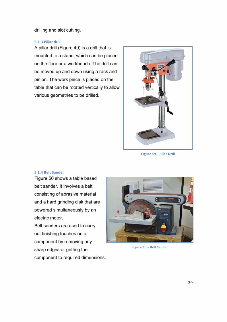
5.1.3 Pillar drill ...................................................................................................................................... 39
5.1.4 Belt Sander ................................................................................................................................... 39
CHAPTER 6 ......................................................................................................................................................... 41
6 Assembly ......................................................................................................................................................... 41
6.1 Exploded View ..................................................................................................................................... 41
6.2 Step by Step Assembly ...................................................................................................................... 42
CHAPTER 7 ......................................................................................................................................................... 45
7 Results and observations ......................................................................................................................... 45
7.1 Prototype ................................................................................................................................................ 45
7.2 Prototype Testing ............................................................................................................................... 48
7.3 Final model ............................................................................................................................................ 49
7.4 Final Model Testing ............................................................................................................................ 51
7.5 Test Results ........................................................................................................................................... 52
CHAPTER 8 ......................................................................................................................................................... 55
8 Discussion ....................................................................................................................................................... 55
8.1 Buckling Forces ................................................................................................................................... 55
Fixed-‐Fixed Strut .................................................................................................................................. 55

iii
Fixed-‐Pinned Strut ............................................................................................................................... 55
Pinned-‐Pinned Strut ............................................................................................................................ 56
Short Pinned-‐Pinned Strut ............................................................................................................... 56
8.2 Rig Mass .................................................................................................................................................. 57
8.3 Problems ................................................................................................................................................. 57
8.4 Design Evaluation ............................................................................................................................... 58
Time ............................................................................................................................................................ 58
Material ..................................................................................................................................................... 58
Safety .......................................................................................................................................................... 58
CHAPTER 9 ......................................................................................................................................................... 60
9 Conclusions .................................................................................................................................................... 60
CHAPTER 10 ...................................................................................................................................................... 62
10 Further work .............................................................................................................................................. 62
10.1 Further Developments and Improvements .......................................................................... 62
10.2 Costs ....................................................................................................................................................... 63
10.3 Distribution ........................................................................................................................................ 64
References .......................................................................................................................................................... 66
Appendix 1 ............................................................................................ Error! Bookmark not defined.
Appendix 2 ............................................................................................ Error! Bookmark not defined.

iv
Table of Figures
Figure 1 -‐ Buckling shapes [5] ...................................................................................................................... 4
Figure 2 -‐ Buckling stress against slenderness ratio [3] ................................................................... 5
Figure 3 – WP121 [7] ........................................................................................................................................ 7
Figure 4 – WP121 Diagram [7] ..................................................................................................................... 7
Figure 5 -‐ WP120 [8] ........................................................................................................................................ 8
Figure 6 -‐ WP120 Diagram [8] ..................................................................................................................... 8
Figure 7 – Aluminium [10] ............................................................................................................................. 9
Figure 8 – Acrylic [11] ...................................................................................................................................... 9
Figure 9 – Brass [14] ...................................................................................................................................... 10
Figure 10 – Spring Steel [13] ...................................................................................................................... 10
Figure 11 – Door Hinge [15] ....................................................................................................................... 10
Figure 12 – Bench Vice [16] ........................................................................................................................ 10
Figure 13 – Slotted Masses [19] ................................................................................................................ 11
Figure 14 -‐ Logarithmic Scale, Overview .............................................................................................. 16
Figure 15 – Linear, Close up ....................................................................................................................... 16
Figure 16 – Fixed Concept 1 ....................................................................................................................... 20
Figure 17 – Fixed Concept 2 ....................................................................................................................... 20
Figure 18 – Fixed Concept 3 ....................................................................................................................... 21
Figure 19 – Pinned Concept 1 .................................................................................................................... 21
Figure 20 – Pinned Concept 2 .................................................................................................................... 22
Figure 21 – Pinned Concept 2.1 ................................................................................................................ 22
Figure 22 – Pinned Concept 2.2 ................................................................................................................ 22
Figure 23 – Frame Concept ......................................................................................................................... 23
Figure 24 – FEA of Top Frame Beam ...................................................................................................... 23
Figure 25 – Top Fixed Concept 1 .............................................................................................................. 24

v
Figure 26 – Top Fixed Concept 2 .............................................................................................................. 24
Figure 27 ............................................................................................................................................................. 24
Figure 28 – Top Fixed Concept 3 .............................................................................................................. 25
Figure 29 – Top Pinned Concept 1 ........................................................................................................... 25
Figure 30 – Top Pinned Concept 2 ........................................................................................................... 25
Figure 31 – Top Pinned Concept 3 ........................................................................................................... 26
Figure 32 – Short Strut Concept 1 ............................................................................................................ 26
Figure 33 – Short Strut Concept 1 ............................................................................................................ 26
Figure 34 – Short Strut Concept 2 ............................................................................................................ 27
Figure 35 – Rendered Rig Assembly ....................................................................................................... 30
Figure 36 – Frame Final CAD ..................................................................................................................... 31
Figure 37 – Loading Plate CAD .................................................................................................................. 31
Figure 38 – Short Test Piece Holder CAD ............................................................................................. 32
Figure 39 – Stands CAD ................................................................................................................................ 32
Figure 40 – Pinned Bottom Bracket CAD .............................................................................................. 33
Figure 41 – Corner Bracket CAD ............................................................................................................... 34
Figure 42 – Top Fixed Holder CAD .......................................................................................................... 34
Figure 43 – Bottom Fixed Holder CAD ................................................................................................... 34
Figure 44 – Top Pinned Bracket CAD ..................................................................................................... 35
Figure 45 -‐ Test Piece Attachment CAD ................................................................................................. 35
Figure 46 -‐ Dimensioned Assembly Drawing ..................................................................................... 37
Figure 47 – Lathe Machine .......................................................................................................................... 38
Figure 48 – Milling Machine ....................................................................................................................... 38
Figure 49 –Pillar Drill .................................................................................................................................... 39
Figure 50 – Belt Sander ................................................................................................................................ 39
Figure 51 -‐ Rig Exploded View .................................................................................................................. 41
Figure 52 -‐ Frame Assembly ....................................................................................................................... 42

vi
Figure 53 -‐ Stand Assembly ........................................................................................................................ 42
Figure 54 -‐ Bracket Assembly .................................................................................................................... 42
Figure 55 -‐ Test Piece Insertion ................................................................................................................ 43
Figure 56 -‐ Test Piece Insertion 2 ............................................................................................................ 43
Figure 57 -‐ Test Piece Insertion 3 ............................................................................................................ 43
Figure 58 -‐ Pin Insertion .............................................................................................................................. 44
Figure 59 – Prototype .................................................................................................................................... 45
Figure 60 – Prototype Top .......................................................................................................................... 46
Figure 61 – Prototype Close-‐up ................................................................................................................ 46
Figure 62 – Test Piece Attachment .......................................................................................................... 46
Figure 63 – Attachment Redesign ............................................................................................................ 47
Figure 64 – Test Piece Comparisons ....................................................................................................... 47
Figure 65 – Fixed/Fixed ............................................................................................................................... 48
Figure 66 – Fixed/Pinned ............................................................................................................................ 48
Figure 67 -‐Pinned/Pinned ........................................................................................................................... 48
Figure 68 – Short Pinned/Pinned ............................................................................................................ 48
Figure 69 – Limiting Bush ........................................................................................................................... 49
Figure 70 -‐ Modified Mass Holder CAD .................................................................................................. 49
Figure 71 -‐ Manufactured bush ................................................................................................................. 50
Figure 72 – Manufactured Weight Plates ............................................................................................. 50
Figure 73 – Rig on Scales ............................................................................................................................. 51
Figure 74 – Scales Readout ......................................................................................................................... 51
Figure 75 – Demonstration of Buckling Shapes ................................................................................. 52
Figure 76 – Short Test Piece Holder Mass ............................................................................................ 53
Figure 77 – Pinned Test Piece Holder Mass ........................................................................................ 53
Figure 78 – Chart Comparing Experimental and Theoretical Results ...................................... 54
Figure 79 – Original Frame ......................................................................................................................... 62

vii
Figure 80 – Proposed Redesign ................................................................................................................ 62
Figure 81 – Original Holder ........................................................................................................................ 63
Figure 82 – Proposed Redesign ................................................................................................................ 63

1
CHAPTER 1
1 Introduction
1.1 Background Buckling is taught in variety of engineering degrees and the fundamentals are
very well established. When lecturing on the topic of buckling there are always
sections that describe the effect different boundary conditions have on the
maximum compressive force that can be applied to the slender member
before it buckles. In addition the maximum compressive force that the
member can be subjected to is length dependent. These principles can be
demonstrated in laboratories where specialized rigs are used which apply
compressive force to members of various lengths until they buckle. However it
is desired to be able to demonstrate similar things in a classroom/lecture
theatre. Smaller demonstration rigs are available on the market but are too
bulky to be carried around.
1.2 Aims and Objectives The aim of the project was to design and manufacture a lightweight and
compact rig to demonstrate the fundamental principles of buckling for use in
classroom conditions. The rig had to be mechanically powered to ensure it
could be used without a power supply.
Following initial research that was carried out on existing products, the
following objectives were set:
• It was decided that the rig must not exceed 5kg in order to be easily
carried around. This however does not take into account the mass of
the weights that will be applied to the struts. [Required]
• The rig must represent Euler bucking [Required]
• Different strut conditions need to be demonstrated to show how the
attachment of the strut affects the buckling when a load is applied.

2
Pinned-pinned, fixed-pinned etc. to show different buckling modes.
[Required]
• Displacement of the struts under load must be measured so numerical
comparison is available along with visual. [Desired]
• Euler buckling can sometimes be inaccurate when slenderness ratio is
less than 50, so demonstration of Rankine-Gordon buckling is desired.
[Desired]
• To prevent the strut from going beyond its elastic limit, safety support is
to be designed to limit the movement and prevent yielding. [Required]
• To fully demonstrate the buckling principles, use of different length bars
must be implemented. [Desired]
1.3 Planning Before the project work commenced, a proposed plan of work was devised:
• Research into existing rigs available for demo – Research and analyse
available products on the market for demonstration of buckling
• Literature review of buckling principles – Review the fundamental
principles of buckling.
• Development of initial design ideas – Research into current designs
and current methods available to realise the objectives and develop
initial ideas. Evaluate initial ideas and develop them into final design.
• Prototyping and manufacture of design – Manufacture and test the
prototype. From testing conclusions and design changes can be made
which can be incorporated into final design.
• Testing – Thorough testing of the design against requirements set.
• Report writing – Report writing to be done progressively as new data
and results are acquired.
After the objectives have been set and the research was carried out a Gantt
chart was produced to ensure that the project was completed on time. The
copy of the Gantt chart can be viewed in Appendix 1.

3
CHAPTER 2
2 Literature review
Buckling – “Long slender members subjected to an axial compressive force
are called columns, and the lateral deflection that occurs is called buckling”.
[1]
2.1 Euler Theory Euler theory is named after a Swiss mathematician Leonhard Euler and is one
of the main buckling theories used to calculate the maximum load that can be
applied to a column before it buckles [2]. This maximum load that can be
supported by a column before it buckles is called the critical load !!.
All calculations are performed on an ideal column, which means the following
assumptions [1, 2, 3] are made:
• The column is made from a homogeneous material i.e. the material
properties are constant throughout
• An ideal column is initially straight when unloaded
• The load is applied directly through the centroid of the cross-section of
the column
• The column is assumed to have a uniform cross-section
• The column behaves in a liner-elastic manner
• Upon buckling the yield stress is not exceeded
The critical load depends on the column cross-sectional dimensions, materials
modulus of elasticity and the length of the column. The greater the length of
the column the less force it takes before it buckles. The dimensions of the
column directly affect the value for the area moment of inertia. Therefore the
higher the moment of inertia ! at the cross-section, the greater the load that
can be supported by the member.

4
Euler critical load (!!) is the maximum load that the column can be subjected
to before it buckles. [1,2,3]
!! = !!!"!"! (2− 1)
Where ! is the modulus of elasticity, ! is the area moment of inertia and !" is
the effective length [4]. As can be seen in Table 1 the value for ! depends on
the boundary condition of the strut and ! is the unsupported length of the
column.
Table 1 – Effective Length [3]
Boundary Conditions Effective Length !"
Fixed - Fixed 0.5!
Fixed - Pinned 0.699!
Pinned - Pinned !
Fixed - Free 2!
Figure 1 shows the different buckling
shapes of the column depending on
the boundary conditions.
Even though Euler theory can provide
an accurate representation of the
buckling load there are some
limitations. Euler theory predicts that no deflection of the column occurs until
the critical load is reached, also the theory predicts that there is infinite
deflection possible at the critical load, and does not take yielding into account.
Figure 1 -‐ Buckling shapes [5]

5
2.2 Rankine-‐Gordon Theory
Rankine-Gordon theory
is typically used for
shorter bars with
slenderness ratio (!)
less than 50. Figure 2
shows Euler, Rankine-
Gordon and
experimental buckling
stresses plotted against
slenderness ratio. It can
be seen that Euler theory
predicts a higher buckling stress than the experimental and the Rankine-
Gordon theory. As the slenderness ratio increases the predictions obtained
from Euler and Rankine-Gordon tend to equal each other.
Slenderness ratio (!) is the ratio of effective length (!!"") of a member to its
radius of gyration (!). [3]
! = !!""! (2− 2)
Where
! = !! (2− 3)
Figure 2 -‐ Buckling stress against slenderness ratio [3]

6
Where ! is the cross-sectional area of the member and ! is the area moment
of inertia.
The Rankine-Gordon formula [3,6] for critical load (!!) is:
!! = !!!
1+ !!! (2− 4)
Where !! is the yield stress of the material, ! is the cross-sectional area, ! is
the slenderness ratio and ! is a constant depending on the material.
! = !!!!!

7
CHAPTER 3
3. Current Products As was mentioned earlier there are some products existing on the market for
basic demonstration of the buckling principles. These products are made by
GUNT Hamburg, which is a German based company that produces
equipment for engineering education. Following are some of their products.
3.1 WP121 This product demonstrates four cases of
Euler buckling. As can be seen in Figure
3 the maximum mass that each strut can
be subjected to before it buckles depends
on the boundary condition. The white
backing provides a clear view of the
buckling shapes. The test bars are made
from stainless spring steel and remain
within the elastic range throughout the
experiment. The product comes with a set of graduated weights, which allow
a precise increase in mass until the
critical load is reached.
The strut length used in this product is
180mm and the dimensions of the
frame are 380x110x270mm (l x w x h).
The approximate weight of the rig is
10kg, not including the weight set.
Figure 41 shows the components that
the rig consists of.
1 1 weight, 2 pinned support, 3 bar, 4 backing wall with grid pattern, 5 fixed support, 6 mount for weights
Figure 3 – WP121 [7]
Figure 4 – WP121 Diagram [7]

8
3.2 WP120 This product demonstrates all cases of Euler
buckling, but can only do so for one
boundary condition at a time. The lateral
deflection of the member is measured
throughout the loading. The product allows
the stresses in the member to remain within
the elastic limit. The bar lengths supplied
with the product range from 350-700mm and
can be accommodated by adjusting the
height of the load-carrying arm. The test bars
supplied also come in a variety of materials
such as aluminium, copper, brass and steel.
The hand-operated spindle allows for progressive application of compressive
load to the bar. The load cell measures the applied force and displays the
value on the pressure gauge. Traverse loads can be applied to the test piece
to generate additional shear force
on the test piece. This lateral
deflection can be measured. The
dimensions for this product are
620 x 450 x 1150 mm (l x w x h)
and the approximate weight is
63kg. Additional sets allow
investigations of various cross-
sectional geometries, eccentric
application of force and also additional traverse loading. Figure 62 shows the
components the rig consists of.
2 1 spindle, 2 height-adjustable load-carrying cross-arm, 3 dial gauge for lateral deflection of test bar, 4 load cell, 5 frame, 6 pressure gauge, 7 device to generate a transverse load, 8 test bar
Figure 5 -‐ WP120 [8]
Figure 6 -‐ WP120 Diagram [8]

9
CHAPTER 4
4 Design & Methodology
4.1 Research Before any initial design ideas were developed, research was carried out into
existing products. The product functionality and the materials used for each
part were studied carefully. One of the most demanding parts of the research
and design phase was developing methods of fixing the test pieces to the
frame and still allow for the end conditions to the attained. GUNT products
used steel for their frames and that made them somewhat heavy [7,8]. None
of the products researched compared different length test pieces side by side.
That had to be incorporated into the design, as that was one of the objectives
set. A suitable size for the frame had to be designed so it can easily be seen
from a distance.
4.1.1 Test Piece Material There were various different materials that could
have been chosen for the test pieces. Aluminium
(Figure 7) was a very easy material to acquire
but due to low Young’s Modulus of 69GPa [9] it
was not suited for use as a test piece.
Aluminium yields under low forces and it is not
very flexible. Aluminium was not suited for this
application.
Acrylic (Figure 8)
was another material that was looked into for use
as a test piece. Young’s Modulus of 3.2GPa [9]
could have caused it to yield under low forces. It
could yield before noticeable deflection of the test
piece occurs.
Figure 7 – Aluminium [10]
Figure 8 – Acrylic [11]

10
Brass (Figure 9) was also considered. With
Young’s Modulus of 100-125GPa [9] it can
provide effective demonstration buckling. One
material that was
suited for such an
application was
spring steel (Figure
10). It has a high
Young’s Modulus of
210GPa [12], which suggested that it will not
yield as easily as the materials discussed above.
In the existing products that are available on the market spring steel was used
as the material for the test pieces.
4.1.2 Boundary Conditions Research for the boundary conditions involved
methods that are in use today to achieve similar
things. For pinned boundary condition a
common door hinge (Figure 11) was considered.
This is a simple yet very effective design that is
used in various applications. It involves two
separate parts rotating around a common fixed
axis.
For a fixed boundary condition means of clamping
could be used. Available methods that currently
exist which provide clamping are vices (Figure 12)
and clamps. By implementing the same technique
into the design, a fixed boundary condition can be
attained by clamping the test piece and prevent it
rotating around the end point.
Figure 9 – Brass [14]
Figure 10 – Spring Steel [13]
Figure 12 – Bench Vice [16]
Figure 11 – Door Hinge [15]

11
4.1.3 Frame Material There was a selection of materials that were considered for use in the frame
design. Aluminium has a density of 2712kg/m3 [17]. This is low compared to
steel, which has a density of 7850kg/m3 [17]. Carbon fiber was also
considered as the material for the frame as it would have made it very light
due to its density of 1740kg/m3 [18]. However carbon fiber was exceptionally
expensive and because of that was excluded from the material selection for
the frame. The frame had to be less than 5kg, as stated in the objectives.
Aluminium had a much lower density than steel therefore it was a more
favorable choice to be used as the material for the frame.
4.1.4 Loading Masses The test pieces had to be loaded to display the
maximum force that a strut could take before
buckling. This could be done using slotted
masses (Figure 13), which are available to
purchase from science equipment suppliers. The
maximum total mass of each set totals up to 1kg,
which is reached in 100g increments.
Figure 13 – Slotted Masses [19]

12
4.2 Research Outcome Before the design ideas were developed some key design decisions were
made. For the rig to be less than 5kg the frame dimensions had to be
designed so that the mass did not exceed this value, for this reason
aluminium was chosen to be the material for the frame due to its low density.
The material for the test pieces had to be spring steel in order to prevent them
yielding under low force. The test pieces had to be dimensioned correctly so
that a reasonable amount of force had to be applied to cause buckling. After
further research and meeting the workshop staff it was noted that the test
piece holders would be under considerable stress. Therefore the rest of the
components had to be designed using mild steel as aluminium would not be
suited for such an application. For the rig to be easily seen a decision was
made that the height of the frame would approximately be 400mm and the
width of 500mm. Spring steel was the chosen material for the test pieces. The
available dimensions for spring steel strips were 0.5mm thick and 16mm wide
[20].

13
4.3 Calculations Using the decisions that were made during research, some basic calculations
were carried out to get the initial dimensions for the design. The design brief
stated that the jig had to demonstrate Euler buckling; therefore this theory was
used to calculate the test piece dimensions. The material used for test pieces
was spring steel with the following properties [12]:
Young’s modulus (!) – 210Gpa
Yield Strength (!!) – 1100Mpa
The strut cross-sectional dimensions remained as discussed earlier.
ℎ = 0.0005 !
! = 0.016 !
! = 0.4 !
The sample calculations were carried out for the strut with fixed-fixed
boundary conditions. So the effective length !!"" was
!!"" = !2 = 0.2 !
x
y

14
Worked out first was the area moment of inertia in x and y directions for a
rectangular cross-section [21,22]
!!! = !ℎ!
12
!!! = 0.016×0.0005!
12 = 1.667×10!!" !!
!!! = !!ℎ12 = 1.067×10!! !!
Therefore the strut will buckle about the x-axis as it has the lower value of !.
Next validity of Euler theory had to be worked out so the slenderness ratio
had to be calculated.
Using the cross-sectional dimensions that were stated earlier, the cross-
sectional area was calculated
! = !×ℎ
! = 0.016×0.0005 = 8×10!! !!
To calculate the radius of gyration ! equation (2− 3) was used
! = !!!!

15
! = 1.667×10!!"
8×10!! = 1.444×10!! !
Therefore the slenderness ratio ! was
! = !!""!
! = 0.2
1.444×10!! = 1385
A graph was plotted of slenderness ratio against the Euler [3] and Rankine-
Gordon [6] buckling forces using slenderness ratio (!) as the variable.
!! =!!!"!!
!! = !!!
1+ !! !!!×!!
The following graphs show the variation in buckling force with slenderness
ratio (!) for Euler and Rankine-Gordon theories. Figure 14 shows a wide
range for the slenderness ratio and it can be seen how Euler and Rankine-

16
Gordon curves correspond to each other up until the slenderness ratio (!)
drops below 150. This can be viewed in greater detail in Figure 15.
Figure 14 -‐ Logarithmic Scale, Overview
Figure 15 – Linear, Close up
1
10
100
1000
10000
100000
1000000
10000000
100000000
0 500 1000 1500 2000 2500 3000
Buckling Force
(N)
Slenderness Ratio (k)
Graph Showing Buckling Force Variation with Slenderness Ratio
Euler
Rankine-‐Gordon
0
2000
4000
6000
8000
10000
0 50 100 150 200 250
Buckling Force
(N)
Slenderness Ratio
Graph Showing Buckling Force Variation with Slenderness Ratio
Euler
Rankine-‐Gordon

17
As can be seen in Figure 15, Euler theory began to deviate from the Rankine-
Gordon theory at a slenderness ratio ! of approximately 150. This means that
for this particular case the Euler theory should not be used for ! < 150. To
make the results more presentable a logarithmic scale was used for ‘Buckling
Force’ in Figure 14.
Since the calculated slenderness ratio ! for the fixed-fixed strut exceeded the
value of 150 it is accurate to use the Euler theory.
! = 210!"#
Using equation (2− 1)
!! = !!!"!!""!
!! = !!×210×10!×1.667×10!!"
0.2! = 8.638!
Next to ensure that yielding of strut did not occur under applied force
!!"# = !!"! =
8.6388×10!! = 1.08!"#
!!"# < !! And the ratio of !! !!"#
= 1019: 1 suggested the strut is extremely
unlikely to yield at any point during its operation lifecycle.

18
The validity of Euler theory was verified even further by calculating the
Rankine-Gordon critical force using equation (2− 4)
!! = !!!
1+ !! !!!×!!=
1100×10!×8×10!!
1+ 1100×10! !!×210×10!×1385!= 8.635!
The values obtained for the Euler buckling and the Rankine-Gordon buckling
loads are the same. Therefore Euler theory is valid for the chosen strut
dimensions.
The following calculations were carried out for all four struts. The results are
shown below in Table 2.
Table 2 – Theoretical Critical Loads
! (!) !!"" (!) !!! (!!) !!! (!!) ! !! (!) !!(!) Mass (kg)
0.4 0.2 1.667x10⁻¹³ 1.067x10⁻⁸ 1385 8.64 8.64 0.88
0.4 0.28 1.667x10⁻¹³ 1.067x10⁻⁸ 1937 4.42 4.42 0.45
0.4 0.4 1.667x10⁻¹³ 1.067x10⁻⁸ 2771 2.16 2.16 0.22
0.3 0.3 1.667x10⁻¹³ 1.067x10⁻⁸ 2078 3.84 3.84 0.39

19
The longest test piece length was designed to be 400mm so the frame would
have to be built around that maximum dimension. The width was kept at
500mm. An excel spread sheet was created to calculate the final theoretical
mass of the frame depending on the inputs for the dimensions. The material
density for aluminium was taken to be 2700kg/m3 [17]. The chosen
dimensions were put into the spread sheet giving the theoretical mass of the
frame. Only the mass of the frame was calculated because it would contribute
the most to the mass of the rig.
The calculations involved basic equations such as
!"## = !"#$%&' × !"#$%&
And
!"#$%& =!"#$ℎ × !"#$ℎ! × !"#$%ℎ
Table 3 – Frame Dimensions and Predicted Mass
Side Side Top Bottom
Width (m) 0.03 0.03 0.03 0.03
Length (m) 0.43 0.43 0.5 0.05
Thickness (m) 0.015 0.015 0.02 0.015
Volume (m3) 0.000194 0.000194 0.0003 0.000225
Mass (kg) 0.522 0.522 0.810 0.610
Total Theoretical Mass of Frame – 2.464kg

20
4.4 Initial Ideas The initial design process started out with some rough sketches of ideas.
These sketches were dimensionless but showed the basic functionality of
each part.
4.4.1 Fixed Figure 16 shows a basic method of
how a fixed boundary condition can be
attained. The block is cut in half and
slot is milled out in each half to hold
the test piece. The block is screwed
together. The test piece is clamped in
a block, which prevents it from
pivoting thus creating a fixed boundary
condition. One of the problems with
this design was that the holes that
were required to fix the block to the frame will have to be off-centre so
manufacturing would be complex. Figure 17 shows another alternative to
fixing the test piece. Instead of cutting the block in half and milling a slot in
both halves, a slot is simply milled
into the block near the edge.
However after some research on
tool sizes it was discovered that a
small enough diameter tool was
not available to mill out a slot that
wide, particularly through the whole
block.
So another variation of this design
was developed which also involved
clamping of the test piece.
Figure 16 – Fixed Concept 1
Figure 17 – Fixed Concept 2

21
As can be seen in
Figure 18 this is done
by milling out a slot in
the side of the block
and then clamping it
with a plate. The block
is securely attached to
the frame. This design
is relatively easy to
manufacture.
4.4.2 Pinned Figure 19 displays a simple way of
recreating a pinned boundary
condition experimentally. A
triangular dip is made on the top
surface of the block. This can be
done by approaching the surface
of the block at a 45° angle with a
milling machine and milling into it.
The test piece can rest inside the
dip and pivot about the point
where it rests. The test piece will
be under compression so it will not slip out of the dip. The manufacture of this
design requires very proficient use of workshop equipment. While the test
piece will remain in the groove during operation of the rig it can easily fall out
when the rig is being transported.
Figure 18 – Fixed Concept 3
Figure 19 – Pinned Concept 1

22
To ensure the test piece remains fixed during transportation another method
was developed. This method can be seen in Figures 20,21&22.
Figure 20 shows a pinned
boundary. This method uses a
door hinge type mechanism
where the test piece pivots
around the pin, which is
stationary inside the block thus
creating a pinned boundary
condition. This is done by fitting
a bracket to the end of the test piece
(Figure 21), which has a hole in it for the
pin to fit through.
An alternative method for attaching the
test piece to the block can be seen in
Figure 22. This involves bending the end
of the test piece so a pin can fit through it
and be able to pivot. However because
the preferred
material for the test
piece is spring steel this would be difficult.
The only way that this could be achieved is by using
untreated spring steel and then heat-treating it once the
shaping procedure has been carried out. Fulfillment of
this idea was likely to be very time consuming.
4.4.3 Frame
Figure 20 – Pinned Concept 2
Figure 21 – Pinned Concept 2.1
Figure 22 – Pinned Concept 2.2

23
Figure 23 shows a simplified idea
for a frame. The frame will hold
together all the components, which
will be fixed to it. The blocks are
fixed at the bottom and the top
beam will support the loading
plates as well as the mass that will
be applied to them. This means
that the top beam will need to be
thick enough to prevent any
deflection. To increase the frame
stability stands are added to it. An FEA simulation was carried out to
determine if the top beam was thick enough to support the mass of the
weights that were going to be applied to the rig. The result is shown in Figure
24 below. The thickness of the top beam was taken to be 0.02m. It can be
seen that when a load of 100N is applied evenly over the beam it deflects.
The simulation shows that the maximum deflection that occurs is 0.0228mm.
This ensures that the top beam is thick enough as the load is not going to be
as high as 100N at any point of the rigs operation.
4.4.4 Top fixed
Figure 23 – Frame Concept
Figure 24 – FEA of Top Frame Beam

24
This section will talk about various methods that a
fixed boundary condition can be realised. It was
somewhat harder to recreate boundary condition for
the top of the test piece than the bottom since it
moves up and down. The idea was to use a round
bar as the starting point for the holder. This meant
that a hole can be drilled in the top part of the frame
and the holder can fit through it.
Figure 25 shows one of the initial ideas that was
originated. The holder uses a round bar and the end
is machined into a semi-circular shape. A hole is
drilled in the test piece and is then screwed to the
holder. This prevents the test piece pivoting and
therefore acts as a fixed joint.
Next idea (Figure 27) uses a similar concept
except the holder consists of two diameters. The
slot is milled into the larger diameter, which
provides side support
for the test piece. The
test piece is also bolted
to the holder, which
prevents pivoting. This
meant that it could be
easily manufactured
because there are only
a few basic turning and
milling operations that
needed to be carried
out.
Figure 25 – Top Fixed Concept 1
Figure 26 – Top Fixed Concept 2
Figure 27
!

25
Possible problems that can occur with these
designs is that the test piece is not completely
fixed when it is bolted down. As the test piece is
loaded it might move away from the holder. This
is shown exaggerated in Figure 26. It will result
in the joint becoming a mixture of fixed and
pinned. To prevent this from happening the
whole area of the test piece inside the holder
would have to be pressed down. Figure 28
demonstrates the method that will permit this. It
consisits of two parts and both have a semi-
circular shape. A slot is milled out in each part to
house the test piece and two parts are bolted
together pressing on the test piece, similar to a vice.
4.4.5 Top pinned Similar to the previous section this will discuss the
various ideas for realising a pinned boundary condition
at the top of the strut. Figure 29 shows an idea similar
to the one for the bottom pinned holder. It involves
milling a slot in the same way by approaching the
surface at a 45° angle. This however is not as effective
because the holder will
have to constantly apply
pressure to the test piece
to prevent it from
dropping out.
Figure 28 – Top Fixed Concept 3
Figure 30 – Top Pinned Concept 2
Figure 29 – Top Pinned Concept 1

26
Consequently another method had to be developed. Next idea (Figure 30)
was developed from a door hinge. It involves a circular bar similar to that from
previous ideas. The end of the bar is machined into a hinge. The circular end
fits through the frame and the other end attaches to a test piece. The hole in
the hinged piece allows for a nut and bolt to be used to secure the test piece.
This design would work very well but could be difficult and excessively time
consuming to manufacture. Another idea involved a similar method of using a
hinge, but in a much simpler way from a
manufacturing point of view.
This idea is seen in Figure 31 and it involves milling
out a slot in the wider end of the holder with a hole
drilled straight through. An attachment is fixed to
the test piece and a pin is then inserted through
which allows the test piece to pivot. This design will
be easy to manufacture as it involves a few basic
operations on the lathe and milling machine.
4.4.6 Short strut pinned The shorter strut had to have an extended top holder. Because of the
increased length of the holder some lateral support had to be provided to
prevent it from tilting, which can result in jamming. As can be seen in Figures
32&33 a bracket is fixed to the frame, which
provides support for the test piece holder.
One part of
the bracket is
secured to the
frame and the
other has a
hole through
which the
holder fits. This
Figure 31 – Top Pinned Concept 3
Figure 32 – Short Strut Concept 1
Figure 33 – Short Strut Concept 1

27
provides two axially aligned points that support the holder forcing it to move
strictly in the vertical direction.
This is an excellent idea however if during the manufacturing process the
bracket is misaligned with the top hole, the
holder will jam and the rig will not function
properly. For this reason another idea was
produced, which can be seen in Figure 34.
This idea follows the same principle of
providing support for the holder but does it in
a slightly different way. The original hole in
the frame is made bigger and a bush is
inserted with the same internal diameter as
the diameter of the holder. This provides lateral support for the holder.
Concept 2 is simple to manufacture and does not require as much accuracy
as manufacturing a bracket.
Figure 34 – Short Strut Concept 2

28
4.5 Rig Design Development Following evaluation of initial ideas, they then underwent a number of
revisions with added dimensions. The rig had to be self manufactured so
every part of the design had to be simplified to ensure that it was not too
complex to fabricate. This meant that every part had to be made using only
basic workshop machinery and in a realistic period of time.
The materials for the manufacture of the rig were provided by the university
workshop, so the available raw material dimensions had to be considered
when finalising the dimensions for the rig. This was to ensure that minimum
material wastage occurred and also to cut down the fabrication time, which
could increase if a lot of material had to be removed in order to end up with a
part.
Throughout the design process the simplicity of assembly was always
considered. All the parts had to be assembled with ease. The test pieces had

29
to be easily replaced for whatever reason, such as yielding or changing the
material.
4.6 Final Idea CAD Figure 35 shows the final rig assembly from two different angles. As can be
seen there are four test pieces each with a different boundary condition. The
masses are placed on the loading plates at the top. A detailed breakdown of
the components follows.

30
Figure 35 – Rendered Rig Assembly
4.6.1 Frame The frame (Figure 36) had to support the mass that was going to be applied to
it and also house all the components, so it had to be rigid. The top part of the
frame was made thicker, 20mm compared to 15mm for the sides and the
bottom. This was in order to prevent noticeable deflection occurring. Another
way of achieving this would have been to place a support in the middle, hence
reducing the effective length of the top beam. But simply increasing the
thickness was enough to achieve this. The results acquired from FEA analysis
2
3
6
5
4
8
7
1
9

31
(Figure 24) showed that this thickness was enough to prevent the top beam
from deflecting under load. The frame was going to be assembled together by
bolting through the holes that can be seen in the image. The frame had all the
holes designed in precise positions so that all the components are aligned to
ensure accurate operation of the rig, for this reason the frame was designed
last.
Figure 36 – Frame Final CAD
4.6.2 Loading plates The loading plates (Figure 37) were designed
to hold the mass that was going to be applied
to the test pieces. This had to be done so
that the weights did not fall off if the rig was
nudged. The plate was designed to be made
from one part and had a threaded rod at the
Figure 37 – Loading Plate CAD

32
bottom of it so it can be attached to the test piece holders. Splitting the plate
and the holder into two parts was done in order to achieve easy assembly;
otherwise it would have been impossible to assemble it.
4.6.3 Short test piece holder As discussed in the initial design section the short test piece had to have extra
support in order to prevent it jamming inside the hole. There were two
alternatives for this application. One made use of the bracket, which attached
to the side of the frame and an alternative was a bush that had to be inserted
into the top beam of the frame.
The concept with the bush was
chosen (Figure 38). This was
done because the bracket
concept would have been
difficult to accomplish and
required use of different
manufacturing methods such
as welding, bending and drilling.
This simple concept shown only
required the use of a lathe.
This idea was chosen for its simplicity. The bush uses an aluminium rod with
an outside diameter of 14mm and a 10mm hole inside it. Which is press fitted
into the frame.
4.6.4 Stands Evidently the rig had to stand by
itself on a flat surface and needed
to be stable. However due to the
mass limitation that was set, the
stands had to be low weight but
still provide a wide base. For this
Figure 38 – Short Test Piece Holder CAD
Figure 39 – Stands CAD

33
reason a triangular stand was chosen and it was made from aluminium
(Figure 39).
It has a wide base and all the excess material is removed to reduce the mass
while still remaining rigid. The stands are made from 3mm thick aluminium
sheet and are manufactured using a milling machine. Alternatively this could
be done using CAM. The stands are attached to the frame using thee M3
screws.
4.6.5 Pinned Bottom Bracket Initial design of the bracket considered the
use of aluminium. The final design (Figure
40) used mild steel as the material. This was
due to the fact that after discussions with
project supervisor it was decided that the
bracket would be under stress and aluminium
might not be suited for this. For safety and
durability of the part it was decided to use
mild steel. This design was chosen over
others because it was much easier to realise.
It allowed easy replacement of test pieces and didn’t require changing the
shape of the test piece in order to attach it to the bracket. Additionally it
provided a pinned condition and it could be easily fixed to the frame.
4.6.6 Corner Bracket The corner brackets (Figure 41) were made
from aluminium and were added to the
frame to increase its rigidity. They are fixed
to the corners where the horizontal and
vertical beams of the frame meet. The
brackets were made from 3mm thick
Figure 40 – Pinned Bottom Bracket CAD

34
aluminium and attached to the frame using two M2 screws.
Theoretically the brackets do not weight much but significantly improve the
rigidity of the frame.
4.6.7 Top fixed holder Figure 42 shows the top fixed holder. It uses
a steel rod of 20mm diameter on which the
top part is turned to 10mm.
The big end is milled to give a semi-circular
shape and the small part is manufactured
separately from a round bar. Two parts aren’t
exactly symmetrical and the removable side
has a slot milled in it. Because of this the
centre is slightly offset but this allowed the
test piece remain in line with the centre-line of
the holder. Initial idea of this design involved a slot being milled out in both
sides, but this was impractical because it was impossible to mill a rectangular
groove on the main part of the holder. That would have resulted in a circular
corner. The semi circular shape acts as a clamp, which locks the test piece.
This holder was made from mild steel since a lot of stress would be applied at
the point where the test piece is clamped. The top of the holder had a
threaded hole, which as discussed earlier allowed easy assembly for the
loading plate to be screwed in.
4.6.8 Bottom fixed holder Similar to the pinned bottom bracket
this bracket (Figure 43) was made from
mild steel for the same reason. This
was chosen over other designs due to
its practicality. The holder consists of
two parts, the main block with a 10mm
wide slot milled out and a plate, which
Figure 41 – Corner Bracket CAD
Figure 42 – Top Fixed Holder CAD
Figure 43 – Bottom Fixed Holder CAD

35
is bolted to it using two M3 screws. The dimensions of the block are 30x20x15
mm, which are the same as pinned bracket block. This was to simplify the
design and allow faster manufacture since making a square bar the right
dimension and splitting it into four small blocks is more productive than
making them individually.
4.6.9 Top pinned bracket The top bracket (Figure 44) has a 10mm slot milled out to accommodate the
test piece and the attachment that is
bolted to it. It is made from mild steel
and has a 2mm pin going through
around which the test piece pivots. At
the top it has a threaded hole in which
the loading plate is screwed. It was
designed to be turned from a round
bar of 20mm diameter. This was
selected over other ideas due to ease
of fabrication and simplicity.
4.6.10 Test-‐piece attachment The part shown in Figure 45 attaches
to the test piece that will require a
pinned boundary condition. A slot was
milled out to accommodate the test
piece that was firmly secured by an M3
nut and bolt. And a 2mm hole for the
pin around which the test piece will
Figure 44 – Top Pinned Bracket CAD
Figure 45 -‐ Test Piece Attachment CAD

36
pivot. This part is fabricated from mild steel to increase its durability.
4.7 Engineering Drawings

37
Because the design had to be manufactured engineering drawings of each
part were also produced from the CAD design. Figure 46 shows useful
dimension of the final rig design.
Figure 46 -‐ Dimensioned Assembly Drawing
The remainder of the drawings can be viewed in Appendix 2.

38
CHAPTER 5
5 Manufacturing Because the outcome of this project depended on the quality of manufacturing
the main equipment used for manufacture will be briefly covered in this
section.
5.1 Machinery used This section describes the machinery that was used throughout the
manufacturing process
5.1.1 Lathe Machine A lathe operates by rotating
the work piece about its axis.
The work piece is clamped
between self centering jaws
as can be seen in Figure 47
and is rotated at various
speeds depending of the work
piece dimensions. The tool is
moved in two horizontal axes
to remove the material about
the axis of rotation.
5.1.2 Milling machine The milling machine (Figure
48) operates by clamping the
work piece in the vice, which
is fixed to a table. This table
can be moved in x, y and z
axes. Milling machines are
typically used for planning,
Figure 47 – Lathe Machine
Figure 48 – Milling Machine
39
drilling and slot cutting.
5.1.3 Pillar drill A pillar drill (Figure 49) is a drill that is
mounted to a stand, which can be placed
on the floor or a workbench. The drill can
be moved up and down using a rack and
pinion. The work piece is placed on the
table that can be rotated vertically to allow
various geometries to be drilled.
5.1.4 Belt Sander Figure 50 shows a table based
belt sander. It involves a belt
consisting of abrasive material
and a hard grinding disk that are
powered simultaneously by an
electric motor.
Belt sanders are used to carry
out finishing touches on a
component by removing any
sharp edges or getting the
component to required dimensions.
Figure 49 –Pillar Drill
Figure 50 – Belt Sander

40
Table 4 shows the equipment used during manufacturing of specific components.
Table 4 – Machinery Used
M
illin
g M
achi
ne
Lath
e M
achi
ne
Pill
ar D
rill
Bel
t San
der
Ban
d S
aw
Frame O
O O
Loading Plates
O
Short Test Piece Holder
O
O
Stands O
O
Pinned Bottom Bracket O
O O
Corner Bracket O
O
Top Fixed Holder O O O O
Bottom Fixed Holder O
O
Top Pinned Bracket O O O O
Test Piece Attachment O
O O O

41
CHAPTER 6
6 Assembly This section will briefly describe the assembly process of the rig.
6.1 Exploded View Figure 51 below shows the exploded view of the rig before its assembly.
Figure 51 -‐ Rig Exploded View

42
6.2 Step by Step Assembly In this section the
assembly process of the rig
will be briefly illustrated.
The assembly of the rig
must begin with the frame
(Figure 52). The frame will
house all the components
hence it is the first thing
that must be assembled.
Care must be taken while
assembling the frame
because it is very easy to
get the left and right side
beams mixed up. Three
holes on the on the side
beams have to be at the
bottom and facing outwards.
This is so the stands
(Figure 53) can be attached
to the frame.
While assembling the rig
attention must be paid to
the force that is used to
tighten the screws.
Because the frame is
made from aluminium it is
very easy to shred the
threads. As soon as
resistance is felt the
tightening can be stopped.
Figure 52 -‐ Frame Assembly
Figure 53 -‐ Stand Assembly
Figure 54 -‐ Bracket Assembly

43
Next step is to attach the bottom brackets to the frame (Figure 54). There is
no preferred orientation
to how this is done
because the brackets are
symmetrical. The main
thing to pay attention to
while attaching brackets
to the frame is the order
in which they go in. If the
frame is viewed from the
front, the order in which the
brackets attach in is fixed,
fixed, pinned, and pinned.
This will ensure that upon
completion the boundary
conditions turn out as
planned.
Once the bottom brackets
are in place the test piece
can be attached to holders
and attached to the frame.
Figure 55 shows how the
holders are inserted into
the frame. This is done
by deflecting the test
piece to the side while
inserting the holder into
the top part of the frame
(Figure 56). Lubricant
must be applied to the
holder prior to assembly.
Figure 55 -‐ Test Piece Insertion
Figure 57 -‐ Test Piece Insertion 3
Figure 56 -‐ Test Piece Insertion 2

44
This will ensure smooth movement and reduce friction of the holder. Next step
is to insert the bottom of the test piece into the bottom holder. This can be
done in two ways. One way is to rest it inside the slot and screw the plate to it
or another way is to semi assemble the block and fit the test piece inside. This
can be seen in Figure 57. After that the screws are tightened to fix the test
piece in place. The process is repeated for other test pieces and the only
difference being that instead of the test piece being clamped a pin is inserted.
Figure 58 shows the pin
being inserted through
the block and the test
piece. Once all the test
pieces are in place the
mass holders are
attached to the top.
The rig took in the region of 5 minutes to assemble and only required two
Allen keys and a screwdriver. The attachment of components was very good
and no problems were encountered during assembly.
Figure 58 -‐ Pin Insertion

45
CHAPTER 7
7 Results and observations This section will discuss the prototype and the final model and their
corresponding testing results
7.1 Prototype The prototype was made four weeks after the drawings were completed. This
closely conformed to the time plan that was created at the beginning of the
project. A few design
modifications were made
during the manufacturing
process. Figure 59 shows
the finished prototype. It
tested whether the design
works, how each
boundary condition
affected the shape of the
test piece. The prototype
was made with test
pieces from different
material, mild steel. There
was a limited supply of
spring steel strips so if anything needed to be redesigned, not enough
material would be available for the fabrication of additional test pieces. These
mild steel test pieces could have been heat treated to provide a closer
behavior to the spring steel however that was not necessary because these
test pieces were scrapped. The mild steel test pieces were a different
dimension to the test pieces that were going to be used in the final model. For
this reason it was meaningless testing how much force it took to buckle them.
The sole purpose of the prototype was to test correct function of all the
components. Because the material used was mild steel, it can be seen that
Figure 59 – Prototype

46
the some of the test pieces have yielded. This is because the rig was
designed for the spring steel members in mind.
As can be seen in Figure 60,
there are no loading plates
attached to the test piece
holders. As stated earlier,
they were not required at
this point.
Throughout the
manufacturing process one
the parts that underwent
modification was the small
steel component that
attached to the pinned test
pieces (Figure 61).
Figure 62 shows the part that was discussed in the
paragraph above. As can be seen it is slightly
different from the final design (Figure 45). During
the manufacturing process some of the tools
required to make this were not available, therefore
the design was revised in the workshop and was
Figure 61 – Prototype Close-‐up
Figure 60 – Prototype Top
Figure 62 – Test Piece Attachment

47
decided that instead of milling a thin slot in the test piece it was easier to take
one side off and simply bolt the test piece to it (Figure 63). This also ensured
quick manufacture as the main profile was milled out in steel plate and then it
was split into five parts.
Figure 64 shows the comparison of the
spring steel test piece (left) and the
mild steel test piece (right). As can be
seen the spring steel test piece is half
the thickness of the mild steel test
piece. For this reason no extensive
testing was done on the prototype of
the rig
Figure 63 – Attachment Redesign
Figure 64 – Test Piece Comparisons

48
7.2 Prototype Testing
As can be seen the experimental buckling modes corresponded to the
theoretical modes. Also at this stage the force that took to buckle each strut
was roughly tested. The fixed-fixed took the most force, followed by fixed-
pinned, short pinned-pinned and pinned-pinned.
There were a few modifications that were made to the prototype in order to
make it work properly. The top fixed-fixed support jammed inside the frame,
which provided inaccurate representation of the load that can be applied. The
holes drilled at the top of the frame were not very smooth, so a bush was
designed to be inserted which extended beyond the frame to provide more
lateral support in the same way as it is was for the short test piece.
Figure 67 -‐Pinned/Pinned
Figure 68 – Short Pinned/Pinned
Figure 66 – Fixed/Pinned
Figure 65 – Fixed/Fixed

49
7.3 Final model After some basic tests on the prototype were carried out some additions and
changes were made to the design.
One of the main problems with the prototype was that when force was applied
to the strut it would jam and not return to its initial position. So a bush (Figure
69) was designed to solve this problem. The initial hole was bored out from a
10mm to a 14mm diameter and the
bush was pressed inside from the top.
The bush played two roles. It
prevented the strut from buckling too
much by limiting the downward
movement of the mass and also
provided more lateral support for the
weight plate. This prevented the
weight plate tilting and jamming
inside the hole.
Another modification that
was added was an
extended bolt that
prevents the loading
masses from slipping off
as they are being loaded
on. It can be seen in
(Figure 70) how the bush
protrudes from the top
beam.
Figure 70 -‐ Modified Mass Holder CAD
Figure 69 – Limiting Bush

50
By protruding it provides
more support and limits
the amount by which the
mass holder travels.
Figure 71&72 show the
final manufactured bushes
and weight plates.
Figure 71 -‐ Manufactured bush
Figure 72 – Manufactured Weight Plates

51
7.4 Final Model Testing After the final model was completed, testing was carried out to determine
whether the rig operated correctly and accurately. The objective of the testing
was to compare the practical results of loading the test pieces with the
theoretical results that were calculated before the design stage. Also the total
mass of the rig was measured, as one of the main required objectives was
that the rig does not exceed 5kg.
The rigs mass was measured. This was
done by simply placing the rig on scales
and recording the mass.
As can be seen in Figure 74 the total mass of the rig is 3.3kg not including the
loading masses.
Next to determine the experimental critical load the testing procedure was as
follows:
1. Gradually apply load to the strut in small increments. Increments
depend on the end condition of the strut.
2. Record the force at which the strut buckled
3. Repeat 1&2 until ten sets of readings were acquired
Figure 73 – Rig on Scales Figure 74 – Scales Readout

52
7.5 Test Results
Table 5-‐ Testing Results
Test Number Fixed-Fixed (kg)
Fixed-Pinned (kg)
Pinned-Pinned (kg)
Short Pinned-Pinned (kg)
1 0.80 0.40 0.20 0.27
2 0.85 0.45 0.21 0.26
3 0.80 0.45 0.19 0.28
4 0.75 0.45 0.20 0.28
5 0.78 0.45 0.20 0.27
6 0.76 0.40 0.20 0.30
7 0.83 0.40 0.19 0.28
8 0.8 0.39 0.19 0.28
9 0.8 0.39 0.19 0.28
10 0.8 0.39 0.19 0.28
Average 0.797 0.417 0.196 0.278
Std Deviation 0.029 0.029 0.007 0.010
Theoretical 0.88 0.45 0.22 0.39
Figure 75 shows the masses
under which each strut buckles
and the buckling modes for
each boundary condition.
Figure 75 – Demonstration of Buckling Shapes

53
The results were then edited to
include the mass of the test
piece holders because the
holders contribute to the force
that is needed to buckle the
strut. As can be seen in Figure
76 the mass of the holder for
the short pinned-pinned strut is
111.5g. This means that the
actual average mass applied to
the strut on is
0.278+ 0.112 = 0.39!"
Same applies for the struts with
other boundary conditions. As can
be seen in Figure 77 the other test
piece holder’s weight was around
49g. And the mass of the top fixed
holder was around 70g.
Table 6 shows the average
experimental mass with the mass
of the test piece holders included being compared to theoretical mass.
Table 6 – Results including test piece holder mass
Fixed-Fixed
(kg)
Fixed-
Pinned (kg)
Pinned-
Pinned (kg)
Short Pinned-
Pinned (kg)
Experimental 0.867 0.466 0.245 0.39
Theoretical 0.88 0.45 0.22 0.39
Figure 77 – Pinned Test Piece Holder Mass
Figure 76 – Short Test Piece Holder Mass

54
Figure 78 – Chart Comparing Experimental and Theoretical Results
Fixed-‐Fixed Fixed-‐Pinned Pinned-‐Pinned
Short Pinned-‐Pinned
Experimental 0,867 0,466 0,245 0,39 Theoretical 0,88 0,45 0,22 0,39
0 0,1 0,2 0,3 0,4 0,5 0,6 0,7 0,8 0,9 1
Load
(kg)
Chart Comparing Experimental and Theoretical Results

55
CHAPTER 8
8 Discussion
8.1 Buckling Forces As can be seen from the results obtained in testing, the actual buckling forces
for each strut were within 0.03kg of the theoretical values that were calculated.
This part of the discussion referred to Figure 78
Fixed-‐Fixed Strut The experimental value for the fixed-fixed test piece was 0.867kg, which was
slightly lower than the theoretical value of 0.88kg. This was not unusual
because the results predicted by buckling theories are slightly higher than the
actual. Euler theory predicts that the strut is perfectly straight when unloaded.
The struts used in the rig are constantly under load due to the holder’s mass
acting down on them, this means that the struts already have some initial
deflection prior to loading. The load on the struts could have deviated from the
centroid of the cross-section, which negates another calculation assumption
that the load is applied directly through the centroid of the cross-section.
There is also a possibility that the materials properties aren’t constant
throughout the test piece. Some or all of these factors could have been the
cause of the lower experimental buckling force.
Fixed-‐Pinned Strut The actual value for the fixed-pinned test piece was 0.466kg, which is greater
than the predicted value of 0.45kg. The reasons for this could be that there
was a frictional force due to the top holders sliding inside the bushes. This
caused an increase in the force that was needed to buckle the strut because
that frictional force had to be overcome. This greater frictional force was due
to manufacturing imperfections, which were mainly caused by the operator. In
this case the when holder was inserted inside the bush and moved some
resistance could be felt, this resistance was higher than that of the fixed-fixed
holder. Another possible reason for the greater actual load could be due to the

56
test piece length and cross-sectional dimension variation. The test piece
attachment that was used to allow the test piece to be pinned adds height to
the cross-sectional area of the test piece. The length of the actual test piece
not including the attachment is 385mm compared to the length of 400mm
used in the calculations. It is known from the buckling theory that increasing
cross-sectional area increases the area moment of inertia, which increases
the buckling force that is required to buckle the strut. And decreasing the
length furthermore increases the maximum buckling force that the test piece
can be subjected to. Each one of these could have contributed to the higher
experimental buckling load.
Pinned-‐Pinned Strut The experimental buckling load obtained from testing of the pinned-pinned
strut was 0.245kg. This was also higher than the predicted value of 0.22kg,
mainly for the same reasons as those discussed for the fixed-pinned strut.
This was due to friction and different strut length. The pinned-pinned strut
however has two test piece attachments because both the ends are pinned.
For this reason the actual length of the test piece is 370mm.
Short Pinned-‐Pinned Strut For the short pinned-pinned strut the actual buckling force equals the
predicted force. For this case it was believed that the change in the strut
length directly balances out the errors due to the assumptions made. The
actual length of the strut was 270mm compared to 300mm that was used for
the theoretical calculation. Because the holder moved really smoothly it can
be said that it had very low frictional force, similar to that of the fixed-fixed
holder. The loading could have been eccentric and the strut could have been
initially deflected prior to mass loading. This brings the actual buckling force
below the theoretical. The decrease in the actual length of the strut will bring
the value of the buckling force up therefore balancing out and making the
actual buckling force equal to the theoretical.

57
8.2 Rig Mass It can be seen from the test results that the mass of the rig was 3.3kg. This
differed from the initial predictions of the mass because for the calculations
only the mass of the frame was considered and they were done as a rough
guideline to what the mass would be. The predicted mass of the frame was
2.464kg. The design objective stated that the rig needed to be less than 5kg.
8.3 Problems Throughout the manufacturing process some complications were encountered
which changed the final outcome of the design.
The test pieces that were initially chosen were not available to purchase at the
necessary time as they were out of stock. So as an alternative, the strips of
steel that are used to wrap wooden parcel crates were used as the test pieces.
They had the same dimensions as the researched test pieces. However one
of the problems was that the test pieces were not perfectly straight so they
had to be hammered into shape. This could have changed the mechanical
properties of the material, which in turn could have affected the test results
that were obtained.
The fabrication of the pinned top holder (Fig 44, page 34) proved to be very
challenging. After the slot has been milled a hole had to be drilled
perpendicular to the slot in order for the pin to go through. This proved
problematic, as there were no exact ways of making sure that the hole was
going to be perpendicular to the slot. The solution to that was to use a spirit
level to ensure the slot is in horizontal orientation and drill the hole vertically
downwards, however the accuracy of that method depended on the skills of
the operator. The affect that a non-perpendicular hole had on the strut
behavior is that it caused rotation, which interfered with the desired results.
Similar problems were encountered while manufacturing the test piece
attachments for the pinned joint (Fig 45, page 35). Because the attachments
were cut on a band saw meant the edges were not exactly perpendicular to

58
the hole for the pin. Also some material had to be left spare to allow room for
the width of the blade, so this had to be removed. The method for removing
material used a belt sander. This provided efficient removal but it was not the
most accurate and because of this the attachment shapes were not consistent
and the edges were not always perpendicular to the hole.
8.4 Design Evaluation The test pieces used in the design all had a slenderness ratio greater than
one thousand. That made it safe to assume that the rig represented both
Euler and Rankine-Gordon buckling theories.
Time The manufacture of the design was very time-consuming, taking between
120-130 hours to complete the final product. This time could have been
greatly reduced if the experience level was greater at the planning and design
stage of the project. Due to the lack of experience in manufacturing and
equipment operation some parts designed were impossible to fabricate with
the available equipment. By solely designing each component to allow it to be
easily manufactured, time spent in the workshop could have been reduced
considerably.
Material The choice of material for the rig was successful; the aluminium frame was
very durable but still light enough to be under specified weight. Spring steel
that was used as the test piece material did not yield and provided a good
representation of buckling. The remainder of components that were
manufactured from mild steel could have been redesigned using a different
material to make them lighter. This mainly applies to the top test piece holders
as they had significant masses that provided constant loads on the test pieces.
Safety Operation of the rig necessitated in precautions to be taken. Even though
overall it was safe to operate care had to be taken to ensure the top loading
plates were secured firmly, to prevent the masses falling off and causing
injury to digits and toes. It was advised to wear hard footwear for protection.

59
The rig was designed so that the test pieces remained within the elastic limit,
the bushes (Fig 69, page 48) aided this by limiting the amount by which the
struts deflect. Every boundary condition was demonstrated except the fixed-
free condition, this was left out because this would have made the rig wider
and heavier in order to accommodate five struts instead of four. Because the
fixed-free buckling shape is the simplest to understand it was replaced with a
short pinned-pinned strut. One of the desired objectives was to include the
demonstration of different length bars so the pinned-pinned condition was
used to demonstrate the effect that length has on the buckling force.
Another desired objective was to measure the lateral displacement of the
struts. This feature however was left out from the final design, as it would
have provided no advantageous feedback.

60
CHAPTER 9
9 Conclusions The design fulfilled all the required objectives set by the project supervisor.
The rig successfully demonstrated the fundamentals of buckling since each
boundary condition was represented effectively and showed the
corresponding buckling shapes.
The buckling loads for the fixed-fixed and fixed-pinned struts were within 1.5%
and 3.4% of the theoretical values respectively. The error for the pinned-
pinned buckling load was 10% of the theoretical; this was due to the fact load
applied was small, so even small deviations from the theoretical values gave
high percentage errors. The short pinned-pinned strut gave the buckling load
value that was exactly the same as the predicted buckling load. While the
practical results obtained were averaged from ten sets of readings, it can be
seen how greatly they fluctuated. The buckling load greatly depended on the
way that the operator loaded the strut.
The errors were caused due to defects in the design that were created during
the manufacturing process. These errors could have been greatly reduced if
the rig was made to a greater accuracy.
The main objective that was set stated that the rig could not exceed 5kg. The
final model weighed 3.3kg and even if the loading masses (1kg3) that were
required for demonstration were considered the total mass was still less than
5kg. When this was compared to the products that are currently on the market
it was seen that produced rig was 50% lighter than competing product.
In conclusion a mechanically powered rig was designed and manufactured
that was under 5kg, represented Euler buckling, demonstrated the effect of
3 (500g) x 1, (200g) x 1, (100g) x 2, (50g) x 2

61
different boundary conditions on the buckling load and allowed different length
bars to be subjected to testing.

62
CHAPTER 10
10 Further work
10.1 Further Developments and Improvements
After the design was finished a few ideas have come up that could have
improved the final outcome. So the following are some ideas that could be
incorporated in the design if it is to be manufactured again.
White backing can be added to provide a clear view of the struts behavior
while buckling. A grid can also be added to the backing in order to show how
boundary conditions affect at which point the strut deflects laterally.
Different test piece materials can be selected for demonstration purposes.
The materials that were covered in the research section such as brass,
aluminium and acrylic can be used to display their behavior under
compression. However the strut dimensions would have to be kept the same
in order to show how changing the material affects the value for critical force.
The mass of the rig can be reduced to around 2.5kg and still maintain the
rigidity of the current design. Reducing the dimensions of the frame as can be
seen in Figures 79&80 below can do this. Cutting down the dimensions would
mean that one screw would
have to be used to attach the
beams to each other.
However the bracket at the
back of the frame would
provide the extra support
required.
Figure 80 – Proposed Redesign
Figure 79 – Original Frame

63
Additional improvement that can be made is to reduce the mass of the top test
piece holders by making them out of a combination of materials. Stronger
material can be used where more stress is present and lighter material where
minimal stress is present. So a top pinned holder would
be made of a combination of steel and aluminium. As
shown the Figure 81 the highlighted part should be
made from steel and the smaller diameter to be made
from aluminium to reduce its mass. In addition this will
reduce the initial load on the struts.
To take the demonstration of buckling principles further,
various additions can be
incorporated into the rig such as
adding a torsion element to the compression. This can be
integrated by milling a slot across the surface of the
holder as shown in Figure 82 by a red line. Then a grub
screw can be screwed in to fit in the slot. As the holder
moves downwards the slot will force the holder to rotate
due to the grub screw sitting in it. This will add torsion to
the strut being compressed.
10.2 Costs If the rig was to be manufactured again the cost of materials for one rig are
shown in Table 7 below. All prices quoted from MetalsDepot [23]. Table 7 – Material Costs
Material Cost Estimate
Aluminium Bar – 30x20mm £4
Steel Square Bar – 30x30mm £0.3
Steel Round Bar – 20mm £0.5
Aluminium Plate – 3mm £6
Spring Steel (Test Pieces) £6
Total Cost £16.8
Figure 81 – Original Holder
Figure 82 – Proposed Redesign

64
A sample business plan has been written to show the possibilities if this
design is introduced into the market. The business plan can be accessed from
the CD supplied with the report. The file is titled ‘Compact Jig for Buckling of
Struts Business Plan’.
10.3 Distribution If the rig is going to be distributed to other universities in order to assist with
lecturing then an instruction manual will have to be written to outline the
assembly procedure and operation instructions. A brief operation instruction is
outlined below:
The rig will be supplied with custom made masses that range from 500g to
50g. (500g x 1, 200g x 1, 100g x 2, 50g x 2)
Fixed – Fixed
1. Place 500g mass on
the weight plate
2. Carefully add 200g
on top, some
movement of the
strut should be seen
3. Place 100g mass on
top and the strut
should give way and
buckle. If it does not
then follow step 4
4. Place a further 50g
on top.

65
Fixed – Pinned
1. Place 200g mass on the weight plate
2. Add 100g mass on top, some deflection of the strut should be observed
3. Add a further 100g mass on top and the strut should buckle, if it does
not then follow step 4
4. Place 50g on top
Pinned – Pinned
1. Place 100g mass on the weight plate
2. Add another 100g and the strut should buckle, however if it does not,
follow step 3
3. Place a further 50g on top
Short Pinned – Pinned
1. Place 200g mass on the weight pate
2. Place a further 100g on the weight plate, the strut should buckle. If
buckling does not occur then follow step 3
3. Place 50g on top
The drawings and dimensions for the masses can be viewed in Appendix 2.
66
References
1. Hibbeler R. C. Mechanics of Materials. Third Edition. New Jersey:
Prentice Hall; 1997. p. 654-656
2. Logan D. L. Mechanics of Materials. New York: Harper Collins; 1991. p.
563-565
3. Roy A. Buckling: Bars in Compression [Lecture Notes]. Loughborough:
Loughborough University. [Accessed November 2010]
4. Hibbeler R. C. Mechanics of Materials. Third Edition. New Jersey:
Prentice Hall; 1997. p. 659
5. Logan D. L. Mechanics of Materials. New York: Harper Collins; 1991. p.
573
6. Hearn E. J. Mechanics of Materials 2. Third Edition. Oxford:
Butterworth-Heinemann; 1997. p.28
7. GUNT Hamburg. Company Website:
http://www.gunt.de/static/s3246_1.php?p1=&p2=&pN=#. [Accessed
April 2011]
8. GUNT Hamburg. Company Website:
http://www.gunt.de/static/s3248_1.php?p1=&p2=&pN=;;#. [Accessed
April 2011]
9. Engineering Toolbox Database. Website:
http://www.engineeringtoolbox.com/young-modulus-d_417.html .
[Accessed April 2011]
10. Image: Globo Supply. Website:
http://globosupply.com/index.php?main_page=index&cPath=50_150 .
[Accessed April 2011]
11. Image: http://www.signsbynature.co.uk/images/acrylic-sheet-.jpg .
[Accessed May 2011]
12. Matbase. Material Database. Website:
http://www.matbase.com/material/ferrous-metals/spring-
steel/55si7/properties. [Accessed April 2011]

67
13. Image: http://www.tsmods.com/images/spring_steel.jpg . [Accessed
May 2011]
14. Image: Quick Ship Metals;
http://www.quickshipmetals.com/brass/Brass-sheet.jpg. [Accessed May
2011]
15. Image: http://product-image.esuppliersindia.com/00269746/b/0/Genset-
Canopy-Door-Hinge.jpg. [Accessed May 2011]
16. Image: http://image.made-in-china.com/2f0j00mBdaMoRJlGue/Bench-
Vice-Vise-3-4-5-6-8-.jpg. [Accessed May 2011]
17. Engineering Toolbox Database. Website:
http://www.engineeringtoolbox.com/metal-alloys-densities-d_50.html.
[Accessed April 2011]
18. Carbon Fiber Properties. Website: http://www.carbon-fiber-hood.net/cf-
information. [Accessed May 2011]
19. Image: http://www.philipharris.co.uk/primary/physical-processes/forces-
and-energy/slotted-masses-1kg/?ev=search . [Accessed April 2011]
20. Supplier. Website: http://springsteelstrip.co.uk/2009/11/04/spring-steel-
strip/. [Accessed March 2011]
21. Logan D. L. Mechanics of Materials. New York: Harper Collins; 1991.
[properties of plane areas]
22. Hibbeler R. C. Mechanics of Materials. Third Edition. New Jersey:
Prentice Hall; 1997. [geometric properties of area elements]
23. Supplier. Website: http://www.metalsdepot.com. [Accessed May 2011]


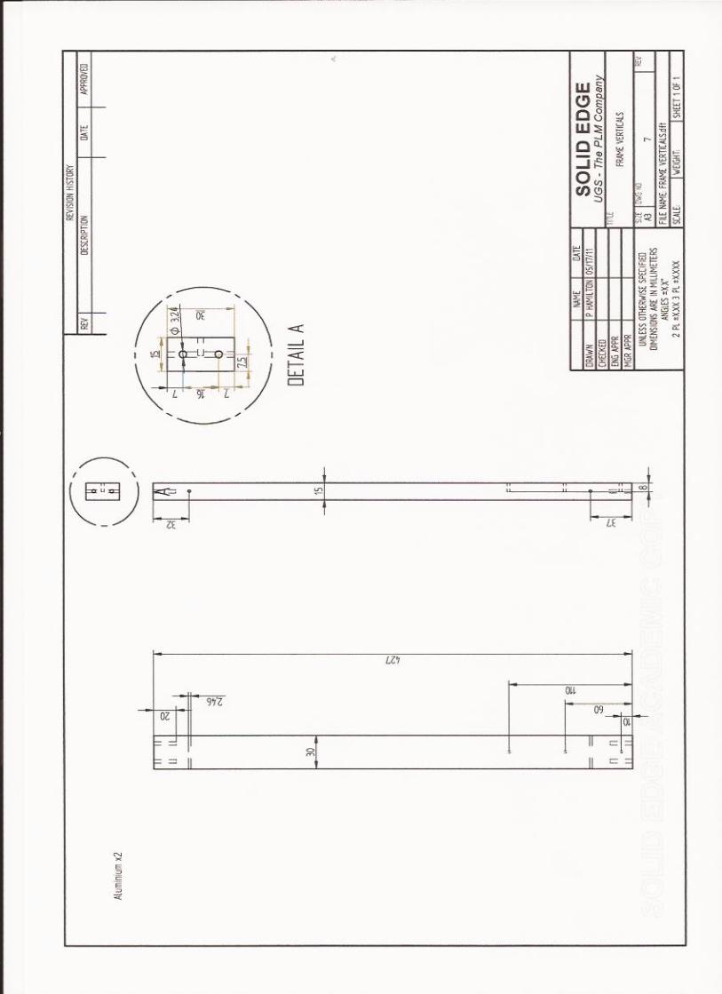


Individual Project Gannt Chart
Compact Jig for Buckling of Beams - Peter Hamilton
Start Date 4.10.2010
Week Number 1 2 3 4 5 6 7 8 9 10
11 Christmas
12
13
14
15 1 2 3 4 5 6 7 Easter 8 9
10
11
12
Week Starting 04.1
0.2
010
11.1
0.2
010
18.1
0.2
010
25.1
0.2
010
01.1
1.2
010
08.1
1.2
010
15.1
1.2
010
22.1
1.2
010
29.1
1.2
010
06.1
2.2
010
13.1
2.2
010
20.1
2.2
010
27.1
2.2
010
03.0
1.2
011
10.0
1.2
011
17.0
1.2
011
24.0
1.2
011
31.0
1.2
011
07.0
2.2
011
14.0
2.2
011
21.0
2.2
011
28.0
2.2
011
07.0
3.2
011
14.0
3.2
011
21.0
3.2
011
28.0
3.2
011
04.0
4.2
011
11.0
4.2
011
18.0
4.2
011
25.0
4.2
011
02.0
5.2
011
09.0
5.2
011
16.0
5.2
011
23.0
5.2
011
30.0
5.2
011
Hand in Objectives Form
Literature Review
Products Review
Workshop Meeting
Generating Initial Design Ideas
Interim Report
Evaluation of Ideas
Interim Presentation
Design Development
Design Documentation
Manufacturing
Testing
Report Writing
Viva voce/Poster
Work Plan
Deadline