compact laser tweezers - opto.cz
TRANSCRIPT
Compact laser tweezers
Mojmır Sery1, Zdenek Lost’ak2, Milan Kalman2, Petr Jakl1, Pavel Zemanek1
1Institute of Scientific Instruments, Academy of Sciences of the Czech Republic,Kralovopolska 147, 612 64 Brno, Czech Republic
2Meopta-optika, s.r.oKabelıkova 1, 750 02 Prerov, Czech Republic
ABSTRACT
In this article we present laser diode based tool for optical manipulation with microobjects. This tool is verysuitable for micromanipulations with large spectrum of speciments in the diameter range 0.5 - 30 µm. Adapteris directly mounted to the microscope without any aditional improvements and fits to many comercially availablemicroscopes. Key feature of this adapter is compactness, usability and simple handling. With this adapteruser takes advantage of wide spectrum of comercially available laser diodes with different wavelengths. For thisreason the tool can be used in many areas such as biology, medicine and measurements.
Keywords: laser tweezers, laser diode, optical manipulation
1. INTRODUCTION
Optical manipulations with light are very popular techniques in many areas of science.1–5 Basic tool is basedon strongly focused laser beam emanating from many types of laser sources – solid state, gas and semiconductor.6
For creation of stable, spatially localized optical trap is necessary to obtain high spatial gradient of light intenzityof trapping beam in the vicinity of focal point. In standard instrument for optical manipulations, e. g. opticaltweezers, this is done by focusing of laser beam by optical system with high numerical aperture. Classicalcomponent suitable for this condition is high-quality microscope objective (water or oil immersion with NAhigher than 1). Commonly used are infinity-corrected types, where collimated laser beam enters back focalplane of microscope objective and overfills back aperture. Standard systems use mainly epi-fluorescent portof the light microscope as an entrance for this beam. Lasers emitting in near-infrared part of optical spectra aremostly used for optical trapping of biological objects due to small influence on environment of these objects.However optical parts of microscopes are optimized for working in visible part of spectra. Main problem iscoating of optical elements of microscope which is optimized for observing image in visible or in some cases inultraviolet region of optical spectra.
Compact optical tweezers (COP) presented in this article overcome this problem by inserting light generatorstraightforward between microscope body and microscope objective. For optical trap generation, the microscopebody is not necessary and instrument can work standalone, the microscope body acts only as support. COPdoes not affect construction of microscope and all features of observing images are well-kept. Presented COPdoes not need presence of epi-fluorescencent port in the microscope body, it is suitable for creating optical trapin low cost types of microscopes. If ultraviolet laser diode is used as laser light source, COP can by used asa optical scissors7–10 or for photopolymerization techniques. COP can act as source for excitation of spectrallines with another types of laser diodes.
Further author information: (Send correspondence to P.Z.)P.Z.: E-mail: [email protected], Telephone: +420 541 514 202, Fax: +420 541 514 402
15th Czech-Polish-Slovak Conference on Wave and Quantum Aspects of Contemporary Optics,edited by Miroslav Miler, Dagmar Senderáková, Miroslav Hrabovský, Proc. of SPIE Vol. 6609, 66090N, (2007)
0277-786X/07/$18 · doi: 10.1117/12.739515
Proc. of SPIE Vol. 6609 66090N-1
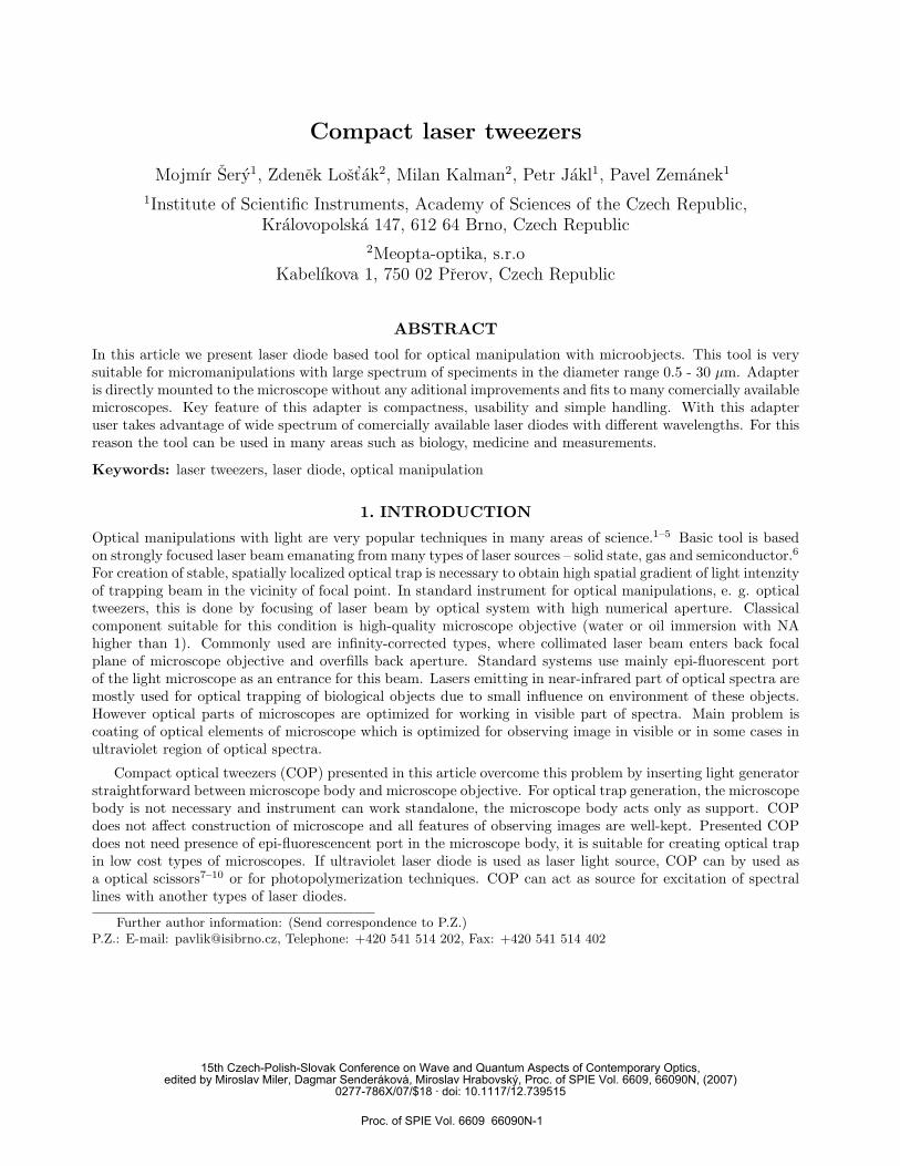
2. CONSTRUCTIONWe used laser diode (Sanyo DL-8031-031A) as a laser radiation source of emitted light with wavelength 808nm and base transversal profile TEM00, maximal output power 200 mW. Emanated beam was collimatedby aspherical lens with focal length 8 mm (Geltech 352240-B) and eliptical beam profile was corrected byanamorphic prism pair (Thorlabs PS871-B).11 This improved beam was than retroreflected by pair of mirrorsinto infinity-corrected microscope objective. The first mirror is coated with multilayer for maximum reflectancefor wavelength of laser diode. The second mirror has multilayer with maximum reflectance for laser diode in onedirection and maximum transmittance for visible light in opposite direction. This optical system was enteredto Zemax optical program (Fig. 1) and optimization was performed. From figures is clearly seen that beam isdiffraction limited, e.g. focus is smaller than Airy disk of optical system. Mechanical construction of the COP
Figure 1. Spot diagram (left), through focus spot diagram (right) from Zemax optical program.
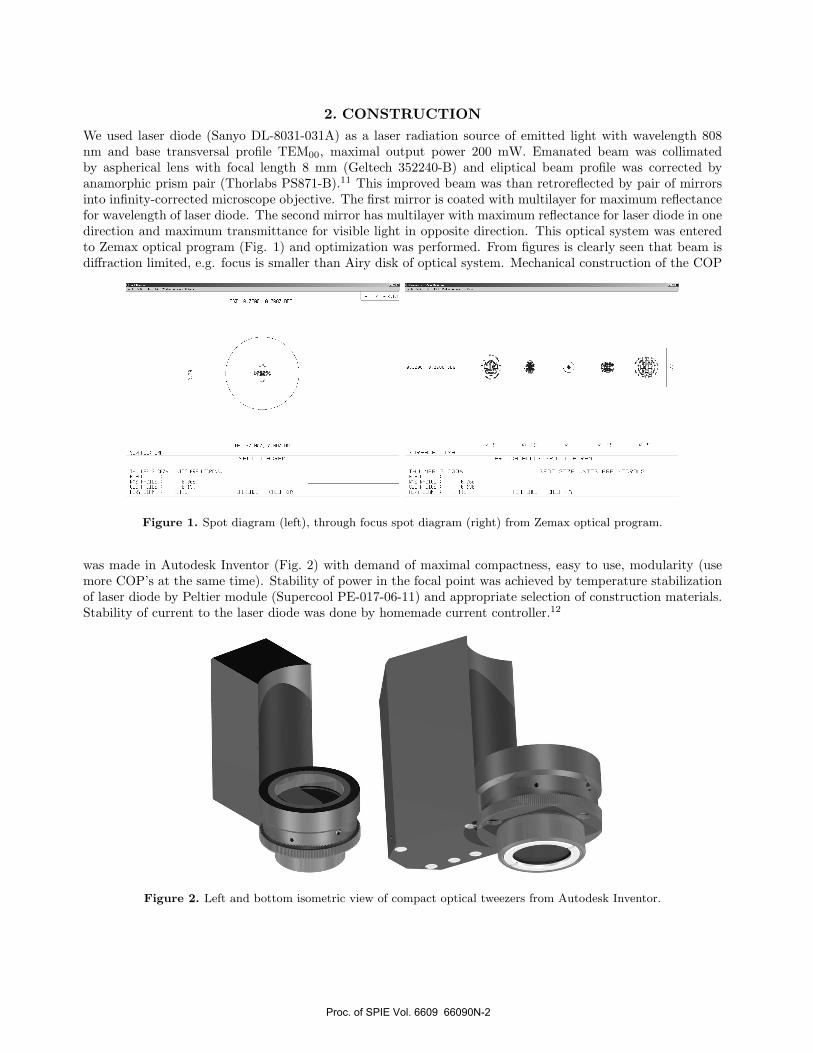
was made in Autodesk Inventor (Fig. 2) with demand of maximal compactness, easy to use, modularity (usemore COP’s at the same time). Stability of power in the focal point was achieved by temperature stabilizationof laser diode by Peltier module (Supercool PE-017-06-11) and appropriate selection of construction materials.Stability of current to the laser diode was done by homemade current controller.12
Figure 2. Left and bottom isometric view of compact optical tweezers from Autodesk Inventor.
Proc. of SPIE Vol. 6609 66090N-2
3. EXPERIMENTS
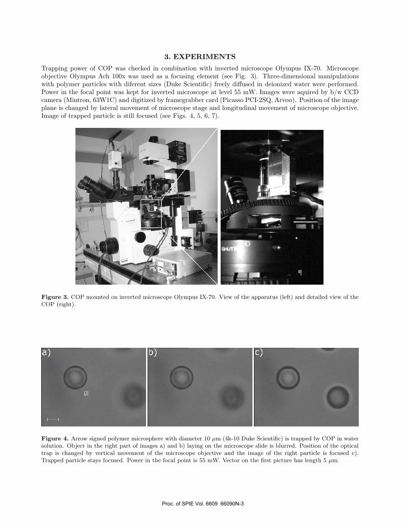
Trapping power of COP was checked in combination with inverted microscope Olympus IX-70. Microscopeobjective Olympus Ach 100x was used as a focusing element (see Fig. 3). Three-dimensional manipulationswith polymer particles with diferent sizes (Duke Scientific) freely diffused in deionized water were performed.Power in the focal point was kept for inverted microscope at level 55 mW. Images were aquired by b/w CCDcamera (Mintron, 63W1C) and digitized by framegrabber card (Picasso PCI-2SQ, Arvoo). Position of the imageplane is changed by lateral movement of microscope stage and longitudinal movement of microscope objective.Image of trapped particle is still focused (see Figs. 4, 5, 6, 7).
Figure 3. COP mounted on inverted microscope Olympus IX-70. View of the apparatus (left) and detailed view of theCOP (right).
Figure 4. Arrow signed polymer microsphere with diameter 10 µm (4k-10 Duke Scientific) is trapped by COP in watersolution. Object in the right part of images a) and b) laying on the microscope slide is blurred. Position of the opticaltrap is changed by vertical movement of the microscope objective and the image of the right particle is focused c).Trapped particle stays focused. Power in the focal point is 55 mW. Vector on the first picture has length 5 µm.
Proc. of SPIE Vol. 6609 66090N-3
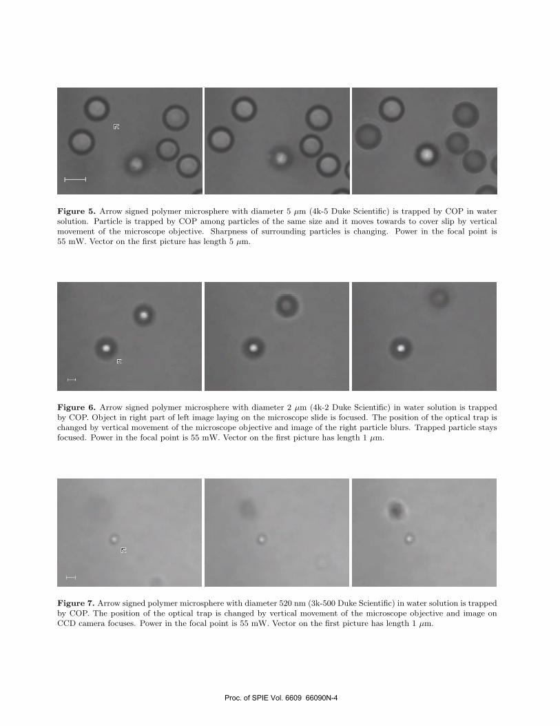
Figure 5. Arrow signed polymer microsphere with diameter 5 µm (4k-5 Duke Scientific) is trapped by COP in watersolution. Particle is trapped by COP among particles of the same size and it moves towards to cover slip by verticalmovement of the microscope objective. Sharpness of surrounding particles is changing. Power in the focal point is55 mW. Vector on the first picture has length 5 µm.
Figure 6. Arrow signed polymer microsphere with diameter 2 µm (4k-2 Duke Scientific) in water solution is trappedby COP. Object in right part of left image laying on the microscope slide is focused. The position of the optical trap ischanged by vertical movement of the microscope objective and image of the right particle blurs. Trapped particle staysfocused. Power in the focal point is 55 mW. Vector on the first picture has length 1 µm.
Figure 7. Arrow signed polymer microsphere with diameter 520 nm (3k-500 Duke Scientific) in water solution is trappedby COP. The position of the optical trap is changed by vertical movement of the microscope objective and image onCCD camera focuses. Power in the focal point is 55 mW. Vector on the first picture has length 1 µm.
Proc. of SPIE Vol. 6609 66090N-4
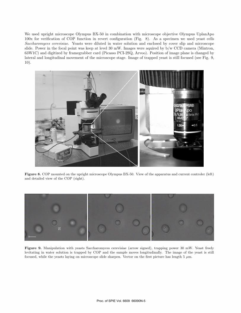
We used upright microscope Olympus BX-50 in combination with microscope objective Olympus UplanApo100x for verification of COP function in revert configuration (Fig. 8). As a specimen we used yeast cellsSaccharomyces cerevisiae. Yeasts were diluted in water solution and enclosed by cover slip and microscopeslide. Power in the focal point was keep at level 30 mW. Images were aquired by b/w CCD camera (Mintron,63W1C) and digitized by framegrabber card (Picasso PCI-2SQ, Arvoo). Position of image plane is changed bylateral and longitudinal movement of the microscope stage. Image of trapped yeast is still focused (see Fig. 9,10).
Figure 8. COP mounted on the upright microscope Olympus BX-50. View of the apparatus and current controler (left)and detailed view of the COP (right).
Figure 9. Manipulation with yeasts Saccharomyces cerevisiae (arrow signed), trapping power 30 mW. Yeast freelylevitating in water solution is trapped by COP and the sample moves longitudinally. The image of the yeast is stillfocused, while the yeasts laying on microscope slide sharpen. Vector on the first picture has length 5 µm.
Proc. of SPIE Vol. 6609 66090N-5
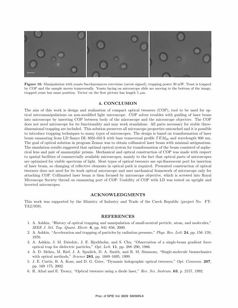
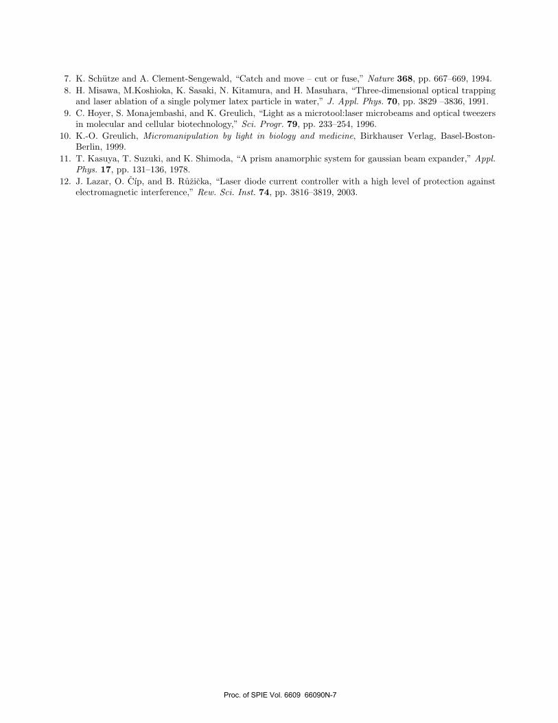
Figure 10. Manipulation with yeasts Saccharomyces cerevisiae (arrow signed), trapping power 30 mW. Yeast is trappedby COP and the sample moves transversally. Yeasts laying on microscope slide are moving to the bottom of the image,trapped yeast has same position. Vector on the first picture has length 5 µm.
4. CONCLUSION
The aim of this work is design and realization of compact optical twezeers (COP), tool to be used for op-tical micromanipulations on non-modified light microscope. COP solves troubles with guiding of laser beaminto microscope by inserting COP between body of the microscope and the microscope objective. The COPdoes not need microscope for its functionality and may work standalone. All parts necessary for stable three-dimensional trapping are included. This solution preserves all microscope properties untouched and it is possibleto introduce trapping techniques to many types of microscopes. The design is based on transformation of laserbeam emanating from LD Sanyo DL 8031-031A with base transversal profile TEM00 and wavelength 808 nm.The goal of optical solution in program Zemax was to obtain collimated laser beam with minimal astigmatism.The simulation results suggested that optimal optical system for transformation of the beam consisted of asphe-rical lens and pair of anamorphic prisms. Mechanical and optical construction of COP was made with respectto spatial facilities of commercially available microscopes, mainly to the fact that optical parts of microscopesare optimized for visible spectrum of light. Most types of optical tweezers use epi-fluorescent port for insertionof laser beam, so changing of reflective elements in optical path is required. Presented construction of opticaltweezers does not need for its work optical microscope and uses mechanical framework of microscope only forattaching COP. Collimated laser beam is then focused by microscope objective, which is screwed into RoyalMicroscope Society thread on emanating port of COP. Usability of COP with LD was tested on upright andinverted microscopes.
ACKNOWLEDGMENTS
This work was supported by the Ministry of Industry and Trade of the Czech Republic (project No. FT-TA2/059).
REFERENCES1. A. Ashkin, “History of optical trapping and manipulation of small-neutral perticle, atom, and molecules,”
IEEE J. Sel. Top. Quant. Electr. 6, pp. 841–856, 2000.2. A. Ashkin, “Acceleration and trapping of particles by radiation pressure,” Phys. Rev. Lett. 24, pp. 156–159,
1970.3. A. Ashkin, J. M. Dziedzic, J. E. Bjorkholm, and S. Chu, “Observation of a single-beam gradient force
optical trap for dielectric particles,” Opt. Lett. 11, pp. 288–290, 1986.4. A. D. Mehta, M. Rief, J. A. Spudich, D. A. Smith, and R. M. Simmons, “Single-molecule biomechanics
with optical methods,” Science 283, pp. 1689–1695, 1999.5. J. E. Curtis, B. A. Koss, and D. G. Grier, “Dynamic holographic optical tweezers,” Opt. Commun. 207,
pp. 169–175, 2002.6. R. Afzal and E. Treacy, “Optical tweezers using a diode laser,” Rev. Sci. Instrum. 63, p. 2157, 1992.
Proc. of SPIE Vol. 6609 66090N-6
7. K. Schutze and A. Clement-Sengewald, “Catch and move – cut or fuse,” Nature 368, pp. 667–669, 1994.8. H. Misawa, M.Koshioka, K. Sasaki, N. Kitamura, and H. Masuhara, “Three-dimensional optical trapping
and laser ablation of a single polymer latex particle in water,” J. Appl. Phys. 70, pp. 3829 –3836, 1991.9. C. Hoyer, S. Monajembashi, and K. Greulich, “Light as a microtool:laser microbeams and optical tweezers
in molecular and cellular biotechnology,” Sci. Progr. 79, pp. 233–254, 1996.10. K.-O. Greulich, Micromanipulation by light in biology and medicine, Birkhauser Verlag, Basel-Boston-
Berlin, 1999.11. T. Kasuya, T. Suzuki, and K. Shimoda, “A prism anamorphic system for gaussian beam expander,” Appl.
Phys. 17, pp. 131–136, 1978.12. J. Lazar, O. Cıp, and B. Ruzicka, “Laser diode current controller with a high level of protection against
electromagnetic interference,” Rew. Sci. Inst. 74, pp. 3816–3819, 2003.
Proc. of SPIE Vol. 6609 66090N-7