compacteurs hydraulique 1a
TRANSCRIPT

PTR BALER AND COMPACTOR COMPANY
2207, ONTARIO E. PHILIDELPHIA, PA 19134 www PTRCO.com
COMPACTEURS HYDRAULIQUE CONÇUE POUR UNE DURABILITÉ SUPÉRIEURE ,
HAUTE QUALITÉ ET SÉCURITÉ MAXIMUM
COMPACTEUR STATIONNAIRE
Compacteur intégré
la sécurité est modèle #______
notre priorité série #_______

TABLES DES MATIÈRES
Introduction......................................................................................................................... 1
Généralités........................................................................................................................... 2
Consignes de sécurité…………………………………………………………………….. 3
Guide de dépannage……………………………………………………………………… 4
Information électrique........................................................................................................ 11
Disposition du tableau de contrôle….…………………………………………………… 23
Instructions d’opération…………………………………………………………………. 25
Information hydraulique...……………………………………………………………….. 26
Renseignements de maintenance…….………………………………………………….. 34
Liste de contrôle de sécurité…………………………………………………………...… 36
Vignette de sécurité mise en page………………………………………………………... 38
Information pièces de rechange………………………………………………………..….. 40
Dispositifs optionnels……………………………………………………………………... 55
Information sur la garantie……………………………………………………………….. 56
Information contrôleur……………………………………………………………………. 57
Contrôleur électrique……………………………………………………………………… 61
CE électrique………………………………………………………………………………. 63

1
INTRODUCTION
Le compacteur hydraulique stationnaire et le compacteur intégré de la PTR Baler and Compactor, sont reconnus dans l’industrie comme étant des produits de haute qualité et de conception supérieure.
Les compacteurs de la PTR Baler and Compactor sont reconnus par l’Underwriters Laboratory et portent le seau d’approbation d’UL, CE et CUL.
Toutes les unités sont inspectées et testées en usine afin de maintenir un niveau élevé de qualité et de s’assurer d'une haute performance à long terme dans le domaine. Plusieurs caractéristiques de conception avancées sur nos compacteurs rendre les operations faciles sans toutefois sacrifier la sécurité. La sécurité de l'opérateur est la priorité numéro un de la PTR Baler and Compactor Co. Nous demandons que tous les opérateurs lisent et comprennent entièrement ce manuel et qu'ils visionnent la vidéo opérationnelle pour votre compacteur. Merci d'avoir choisi un des produits de compacteur Hydraulique de la PTR Baler and Compactor Co.


a) enlever la clef du commutateur de serrure ON-OFF b) éteindre, mettre hors tension, et cadenassé, en s’assurant que le commutateur soit en position OFF, c)
3. Equipment isolation shall be verified by activating the normal operating controls,
ensuring first that no personnel are exposed (insure operating controls are returned to the neutral or “off” position after verifying the isolation of the equipment).
4. When the servicing or maintenance is completed, only after checking that the equipment is ready to operate, ensuring that the surrounding area is clear, that employees are safely positioned or removed from the area, and verifying that controls are in neutral, shall the lockout devices be removed and the equipment be re-energized. Tags and locks must be removed by the same person who attached them.
5. Affected employees shall be notified that the servicing or maintenance has been completed and the equipment is ready for use.
• PTR Baler and Compactor strongly recommends that current and applicable ANSI and OSHA standards be made available to operators at all times. At time of writing the applicable standard is OSHA Standard 29 CFR 1910.147 / 1910.147 appendix A. Also reference ANSI Z245.2, others may also apply. .

PTR Baler and Compactor TO BE COMPLETED BY INSTALLER 2207 E Ontario St.
Please complete and mail/fax this form along with the completed Philadelphia, PA, 10134 Compactor Safety Checklist, immediately after installation Fax: (215) 533 - 8907
PTR Baler and CompactorInformation d'Installation du Compacteur
Information Compacteur :
Model No: . Serial No: .
Installed By: Date: .
Signature of Installer: .
Customer Information:
Customer and Store No: Address: Phone No: Operation and Maintenance Manual Received By: Name & Signature:
Individuals Instructed In Safety Procedures And Operation Of Machine: Names & Signatures:
Keys Received By:
Name & Signature: Operation Video Tape Received By: Title, Name & Signature:
SEE ALSO: COMPACTOR SAFETY CHECKLIST LOCATED IN MANUAL

PTR Baler and Compactor TO BE COMPLETED BY INSTALLER 2207 E Ontario St.
Please complete and mail/fax this form along with the completed Philadelphia, PA, 10134 Compactor Safety Checklist, immediately after installation Fax: (215) 533 - 8907
PTR Baler and CompactorInformation d'Installation du Compacteur
InformationCompacteur :
Model No: . Serial No: .
Installed By: Date: .
Signature of Installer: .
Customer Information:
Customer and Store No: Address: Phone No: Operation and Maintenance Manual Received By: Name & Signature:
Individuals Instructed In Safety Procedures And Operation Of Machine: Names & Signatures:
Keys Received By:
Name & Signature: Operation Video Tape Received By: Title, Name & Signature:
SEE ALSO: COMPACTOR SAFETY CHECKLIST LOCATED IN MANUAL

Compaction Equipment (Continued) Reference Excerpts from American National Standard Z245.2-2004
l) Protecting any person by one of the methods in 5.9.1, or by other means as effective as those means of protection. m) For stationary compactors fed by means of a loading pit conveyor, reciprocating floor, or push pit that is flush with or
below the facility floor, providing:
1) Protection for employees by means of:
i) Limiting access within 6 feet (183 cm) of the edge of the pit to authorized employees; ii) Training authorized employees to recognize and avoid the hazards associated with the pit area; iii) Requiring that others whose employees use the pit area provide assurance of such training; and iv) Limiting access by unauthorized persons by installing signs, such as: "RESTRICTED AREA — AUTHORIZED EMPLOYEES ONLY"
2) Providing a device to the extent practicable, which prevents trucks or other motor vehicles that unload directly into the loading pit from rolling into the pit;
n) When stationary compactors equipped with automatic start/cycling controls are provided, allowing their use only in
locations where a startup alarm is utilized or it is demonstrated that automatic starting does not result in a risk of injury to persons;
o) Providing guard railings for dock ramps that meet U.S. Occupational Safety and Health Administration requirements.
These shall be located around the loading chamber opening if walk-on ramps are used to deposit refuse into the loading chamber. Guard railings and toe boards shall be provided on the sides of docks and ramps;
p) Providing for an adequate work area around the stationary compactor for safe maintenance, servicing, and cleaning
procedures; q) Keeping all surrounding walking areas and floors free from obstructions, and accumulations of waste matter, grease, oil,
and water; r) Maintaining records or employee reports of malfunctions; s) Specifically inspecting safety interlocks, switches, and other protective devices to ensure that these devices are not
disabled or bypassed, and not to permit the stationary compactor to be operated unless these devices are fully functional. These inspections shall be in accordance with g);
t) Ensuring that containers supplied are capable of withstanding the maximum forces generated by the compacting system; u) Ensuring that loaders are aware of hazards and safety requirements; v) Ensuring that only authorized employees (18 years old or older) operate, inspect, or maintain stationary compactors; w) Ensuring that only authorized employees (16 years old or older) load, but do not operate stationary compactors; and x) Incorporating stationary compactors into the employer's safety program (see Section 8). 7.2 Operator and employee responsibilities.
Operators who work on and around the stationary compactor shall be responsible for the items listed below: a) Using all applicable safety features provided on the stationary compactor; b) Using the stationary compactor only after receiving instruction;

Compaction Equipment (Continued) Reference Excerpts from American National Standard Z245.2-2004 c) Reporting any damage to, or malfunction of, the stationary compactor by submitting a report to the employer or
responsible authority when the damage or malfunction occurs; d) Ensuring that access doors and service opening covers are in place, secure, and/or locked before operations begin; e) Ensuring that the area of operation around container/cart lifting systems and the container will be clear of persons during
all phases of the lifting operation prior to energizing the dumping system; f) Ensuring that all persons are clear of the stationary compactor point of operation before actuating any compaction cycle
controls or container/cart lifting system controls and being prepared to stop the compaction cycle or container dumping operation if necessary;
g) Ensuring that all persons are clear of the tailgate (on compactor-container combinations so equipped) before the tailgate
is opened or shut. The operator shall warn all persons not to cross behind or under an open tailgate; h) Using the stationary compactor in accordance the manufacturer’s instructions, including ensuring the proper position of
all locks, doors, guards, etc.; i) Ensuring that no one disables or bypasses safety interlocks, switches, or other protective devices and that the stationary
compactor is not operated unless these devices are fully functional; j) Locking out the unit when inspecting malfunctions, jams, or other problems arising from daily operations; servicing; or
performing maintenance (except maintenance testing). The affected employee shall identify the type and magnitude of the energy that the stationary compactor uses, shall understand the hazards, and know the methods to control the energy (see 7.3);
k) Coupling and securing a compatible container to a compactor frame as specified by the compactor and container
manufacturer(s); l) Operating, inspecting, and maintaining the stationary compactor only if 18 years old or older and after being properly
instructed and trained; and m) Loading, but not operating, the stationary compactor only if 16 years old or older. 7.3 Procedures for the control of hazardous energy sources (lockout/tagout) 7.3.1 The owner/employer shall have a hazardous energy control (lockout/tagout) procedure to follow when performing
servicing and maintenance on stationary compactors where the unexpected energization or start up of equipment, or release of stored energy could cause injury to employees.
7.3.2 The owner/employer shall utilize the instructions provided by the manufacturer for the control of hazardous energy
sources. The lockout/tagout procedure shall isolate and render safe all energy sources, including electrical, mechanical, hydraulic, pneumatic, chemical, thermal or other potential sources of energy (e.g., gravity, kinetic, etc.). It shall be used to ensure that the compactor is stopped, isolated from all potentially hazardous energy sources and locked out before employees perform any servicing or maintenance where the unexpected energization or start-up of the compactor or release of stored energy could cause injury.

Compaction Equipment (Continued) Reference Excerpts from American National Standard Z245.2-2004
7.3.3 The lockout/tagout procedure shall include but is not limited to the following:
a) Shutting down all power sources; b) Removing keys or other devices that enable the stationary compactor; c) Installing a tag on an appropriate location, using a non-reusable fastener, or installing a similar warning device; d) Placing operating components in such a position so as not to be subject to possible free fall and/or installation of
additional blocking devices to prevent such free fall of any raised or elevated component; and e) Relieving stored hydraulic or pneumatic pressure, after blocking devices are installed, if maintenance is to be done
to the hydraulic or pneumatic system.
7.3.4 The procedure shall address the following:
a) Sequence of lockout for the compactor:
1) Notify all affected employees that servicing or maintenance is required on a compactor and that the compactor must be shut down and locked out to perform the servicing or maintenance.
2) The authorized employee shall refer to the company procedure to identify the type and magnitude of the energy that the compactor utilizes, shall understand the hazards of the energy, and shall know the methods to control the energy.
3) If the compactor is operating, it must be shut down by the normal stopping procedure (depress stop button, open switch, close valve, etc.).
4) De-activate the energy isolating device(s) so that compactor is isolated from the energy source(s). 5) Lock out the energy isolating device(s) with assigned individual lock(s). 6) Stored or residual energy must be dissipated or restrained by methods such as grounding, repositioning,
blocking, bleeding down, etc. 7) Ensure that the compactor is disconnected from the energy source(s) by first checking that no personnel are
exposed, then verify the isolation of the equipment by operating the push button or other normal operating control(s) or by testing to make certain the equipment will not operate.
Caution: Return operating control(s) to neutral or “off” position only after verifying the isolation of the equipment.
NOTE: The machine or equipment is now locked out.
b) Restoring the compactor to service. When the servicing or maintenance is completed and the compactor is ready to return to normal operating condition, the following steps shall be taken:
1) Check the machine or equipment and the immediate area around the machine or equipment to ensure that
nonessential items have been removed and that the machine or equipment components are operationally intact.
2) Check the work area to ensure that all employees have been safely positioned or removed from the area. 3) Verify that the controls are in neutral. 4) Remove the lockout devices and reenergize the machine or equipment.
NOTE: The removal of some forms of blocking may require re-energizing of the machine before safe removal. 5) Notify affected employees that the servicing or maintenance is completed and the machine or equipment is ready for use.

Compaction Equipment (Continued) Reference Excerpts from American National Standard Z245.2-2004
7.4 Procedures for work in confined spaces 7.4.1 The owner/employer shall have a written procedure for work in confined spaces meeting the criteria of “permit
required confined spaces," such as integrated power units. The procedure shall utilize the manufacturer’s instructions for the hazardous energy control (lockout/ tagout) procedure which shall isolate and render safe energy sources, including electrical, mechanical, hydraulic, pneumatic, chemical, thermal or other potential sources of energy (e.g., gravity, kinetic, etc.), which may create a hazard during entry into each of those confined spaces.
a) These instructions shall include the requirement to affix a sign to the compactor, at or near the entrances to
those confined spaces for which hazardous energy control procedures are provided, such as, “Warning — Follow lockout/tagout procedures.”
b) These instructions shall include the requirement to affix a sign to the stationary compactor, at or near the
entrances to those confined spaces for which hazardous energy control procedures are provided, such as, “Danger — Confined Space.”
8 Safety and training program 8.1 General 8.1.1 Employers shall evaluate and manage safety issues related to the operation of stationary compaction equipment as part of their safety program. 8.2 Safety program 8.2.1 The employer’s program shall include at a minimum the following elements:
a) A hazard assessment in which the employer conducts a review of the various types of stationary compaction equipment that the employer utilizes and the hazards associated with them and, review and assess the capabilities, qualifications and training of any person who may potentially encounter these hazards.
b) An evaluation of the means and methods of controlling the hazards identified in the hazard assessment, including
information such as industry and regulatory requirements; instructions for the operation, inspection, and maintenance of stationary compactors, and other information appropriate to the hazards that are identified
c) A written program, based upon the hazard assessment and evaluation, to include procedures for the operation,
inspection, and maintenance of stationary compactors, prohibited practices, record keeping, training requirements, and normative references to documents, such as operating manuals, that are relied upon and may be required as part of that program;
d) A program, conforming to 8.2, for the implementation of the written program; and
e) Periodic review and program revisions as necessary to ensure the effectiveness of the safety program.
8.3 General training 8.3.1 Employers shall ensure all employees, including supervisors, contract laborers, and all other persons engaged in the
operation, cleaning, maintenance, service or repair of stationary compacting equipment are properly trained appropriate for their assigned jobs and tasks. Contractors who may be engaged to operate or maintain the employer’s stationary compactors shall be advised of the unique hazards related to the equipment that may affect the activities in which the contractor’s employees will engage.

Compaction Equipment (Continued) Reference Excerpts from American National Standard Z245.2-2004 8.3.2 Training frequency 8.3.2.1 Training shall be provided upon initial assignment to a job or task, with periodic refresher training to maintain the
required level of competence. Retraining shall be provided for employees whenever their job assignments change, or an equipment change occurs that presents a new hazard. Additional retraining shall be provided whenever the employer has reason to believe, or periodic inspections reveal, that employee deviations from procedures have occurred, or inadequacies in the employee's knowledge of procedures become evident.
8.3.3 Instructional information 8.3.3.1 Employers are required to refer employees to, and have readily available, the manufacturer's instructions to ensure
correct operating and maintenance procedures and work practices are understood and followed. Employers are required to ensure employees possess knowledge and skills to safely operate the stationary compactor.
8.3.4 Contract labor 8.3.4.1 Employers shall ensure for each job or task performed that training is provided either by the contract laborer's parent
employer or by the employer. 8.3.5 Training records 8.3.5.1 Employers are required to maintain training records to include the date(s) of the training and the type of training
received. Records are required to be maintained as required by applicable regulations. Contractors and contract laborers are required to provide the employer with appropriate training records upon demand.
8.3.6 Equipment-specific training 8.3.6.1 Training shall be tailored for individual operations and the type of equipment utilized including detailed, equipment-
specific training for machine operators, as well as maintenance personnel and supervisors who must operate equipment as part of their job duties. Training shall include practical demonstration of equipment operation knowledge and skills by the employee, as appropriate to the requirements of the employee’s job duties.
8.4 Training requirements 8.4.1 Training is required to include at a minimum:
a) The necessary training as identified in the hazard assessment [see 8.2.1 a)]; b) The training required by laws and regulations, such as those of federal and state Occupational Safety and Health
Administrations, the Departments of Transportation, and other applicable regulatory agencies; and c) Operational instruction on each specific type of equipment used by the employee, including the instructions
provided with the equipment.


TROUBLE SHOOTING GUIDE (Continued) STATIONARY & SELF-CONTAINED COMPACTORS
RAM WILL NOT MOVE
POSSIBLE CAUSE POSSIBLE REMEDY I. Hydraulic System Pressure is Low 1. Check system pressure
2. Check relief valve for malfunction 3. Worn pump 4. Check for loose intake fittings
J. Pressure Switch 1. Improper pressure setting
2. Bad electrical contact K. Cylinder 1. Check for internal/external cylinder leakage L. Solenoid 1. Check for shifting of solenoid (check light)
HYDRAULIC PRESSURE NOT OBTAINABLE A. Worn Pump B. Cylinder Bypass C. Relief Valve Malfunction D. Improper Pressure Setup E. Loose Fitting

TROUBLE SHOOTING GUIDE (Continued)
UNIT IS NOISY POSSIBLE CAUSE POSSIBLE REMEDY A. Ram Rubbing 1. Cylinder or ram may have material caught
2. Cylinder pin may need grease B. Noise at Directional Valve 1. Directional valve worn
2. Check for broken springs inside valve C. Fan Hitting Shroud 1. Remove shroud & align fan on shaft
- Tighten 2. Realign shroud & tighten shroud bolts . PUMP NOISE POSSIBLE CAUSE POSSIBLE REMEDY A. Oil reservoir level low 1. Check oil level gauge on reservoir (add oil if necessary) B. Worn Pump 1. Check Hydraulic system pressure
C. Restricted Inlet Strainer 1. Replace strainer D. Air leakage in Oil 1. Check for foamy hydraulic fluid in reservoir oil level gauge

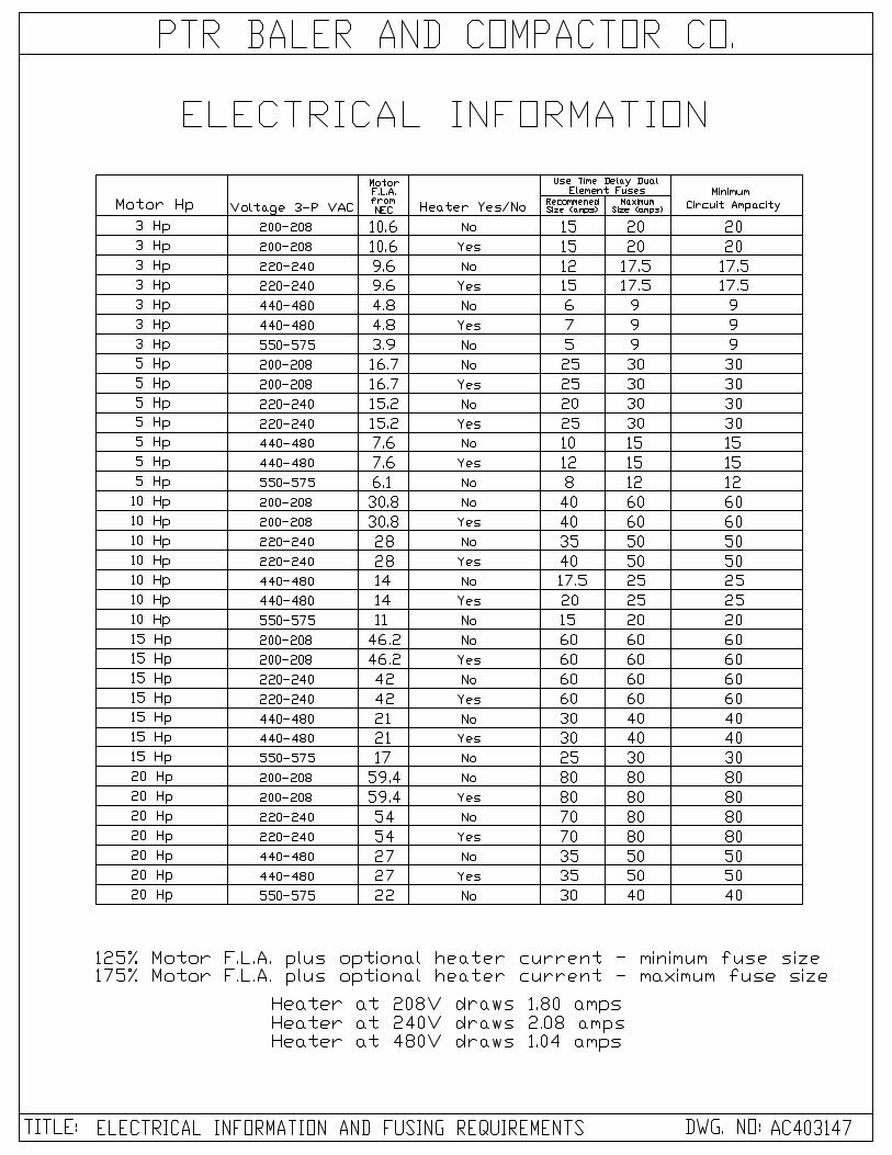
ELECTRICAL INFORMATION
The unit “as shipped” is pre-wired to a specific voltage, as shown on the cover of its’ control panel. The compactor, power unit, and controls may be installed either indoors or outdoors.
CAUTION If your power supply voltage does not agree with the voltage stated on the Compactor control panel cover, DO NOT CONNECT THEM; damage may occur. Have an authorized electrician reset the unit to match your power supply voltage. By “code”, the control panel wire harness must be connected to a properly sized fused disconnect switch. The disconnect switch should be “time delay fuse type” and must be located less than 15 feet and adjacent to the compactor while always within clear view of its operator.
MINIMUM SIZING REQUIRED * “Wire size” denotes wire to be used from power supply to disconnect switch, use heavier wire if distance is more than 25 feet. CONVERSION VOLTAGE: In order to convert the compactor from high to low
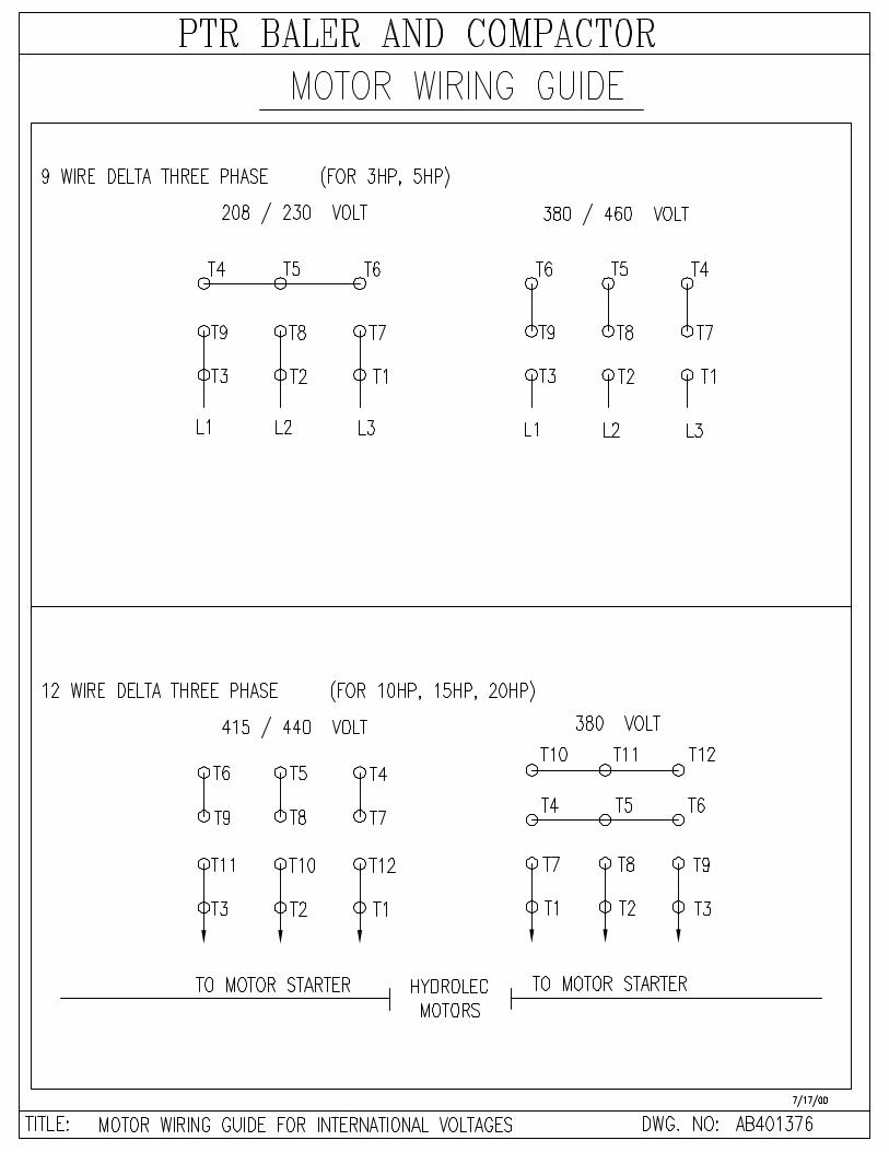
voltage, or vise versa, the following components must be changed: Motor connection as indicated by diagram on motor. Transformer connection as indicated by diagram on transformer. Overload size as indicated by voltage requirements.
IMPORTANT MOTOR ROTATION
When power has been properly connected, press the START button momentarily and observe the direction of the rotation of the motor. Look at the motor fan, proper rotation is clockwise. (If fan rotation is not clockwise, interchange any two of the three power conductors). This should correct the rotation.
CHECK OPERATION Check by following the operating instructions listed on the cover plate of the unit’s control panel.

ELECTRICAL INFORMATION
GROUNDING INSTRUCTIONS
The compactor must be connected to a grounded, metal, permanent wiring system; or an equipment-grounding conductor must be run
with the circuit conductors and connected to the equipment- grounding terminal or lead on the compactor. A qualified electrician
should be consulted if there is any doubt as to whether an outlet box or the machine is properly grounded.
3 HP MOTOR, 3 PHASE, 60 CYCLE Voltage F.L.A. Type Fuse Wire Size Disconnect Switch
200V-208V 10 amp Time Delay 14 30 amp 220V-230V 9 amp Time Delay 14 30 amp 440V-460V 5 amp Time Delay 14 20 amp 550V-575V 4 amp Time Delay 14 20 amp
5 HP MOTOR, 3 PHASE, 60 CYCLE 200V-208V 16 amp Time Delay 12 30 amp 220V-230V 14 amp Time Delay 12 30 amp 440V-460V 7 amp Time Delay 14 30 amp 550V-575V 6 amp Time Delay 14 30 amp
10 HP MOTOR, 3 PHASE, 60 CYCLE 200V-208V 29 amp Time Delay 8 60 amp 220V-230V 26 amp Time Delay 8 60 amp 440V-460V 14 amp Time Delay 12 30 amp 550V-575V 11 amp Time Delay 12 30 amp
15 HP MOTOR, 3 PHASE, 60 CYCLE 200V-208V 43 amp Time Delay 6 60 amp 220V-230V 39 amp Time Delay 6 60 amp 440V-460V 20 amp Time Delay 8 60 amp 550V-575V 16 amp Time Delay 10 30 amp
20 HP MOTOR, 3 PHASE, 60 CYCLE 200V-208V 57 amp Time Delay 4 100 amp 220V-230V 51 amp Time Delay 4 100 amp 440V-460V 30 amp Time Delay 8 60 amp 550V-575V 21 amp Time Delay 8 60 amp


Electrical Information For 50Hz power
GROUNDING INSTRUCTIONS
The compactor must be connected to a grounded, metal, permanent wiring system; or an equipment-grounding conductor must be run
with the circuit conductors and connected to the equipment- grounding terminal or lead on the compactor. A qualified electrician
should be consulted if there is any doubt as to whether an outlet box or the machine is properly grounded.
3 HP MOTOR – 3 PHASE – 50 CYCLE
Voltage F.L.A. Type Fuse Wire Size* Disconnect Switch 380V 5.4 amp Time Delay 14 30 amp 415V 5.2 amp Time Delay 14 30 amp 440V 5.0 amp Time Delay 14 30 amp
5 HP MOTOR – 3 PHASE – 50 CYCLE
380V 8.7 amp Time Delay 12 30 amp 415V 8.0 amp Time Delay 12 30 amp 440V 7.8 amp Time Delay 14 30 amp
10 HP MOTOR – 3 PHASE – 50 CYCLE
380V 17 amp Time Delay 8 30 amp 415V 16.1 amp Time Delay 8 30 amp 440V 15 amp Time Delay 12 30 amp
15 HP MOTOR – 3 PHASE – 50 CYCLE
380V 23.1 amp Time Delay 8 60 amp 415V 22 amp Time Delay 8 60 amp 440V 21.5 amp Time Delay 8 60 amp
20 HP MOTOR – 3 PHASE – 50 CYCLE
380V 29.2 amp Time Delay 8 60 amp 415V 28 amp Time Delay 8 60 amp 440V 27.5 amp Time Delay 8 60 amp
* - “Wire Size” denotes minimum wire size required to be used from power supply to disconnect switch. Use a heavier wire if distance is more than 25 feet.


COMPACTOR OPERATING INSTRUCTIONS 1. Close and latch Security Door. 2. Insert Power On/Off Key and turn to ON position. 3. Press Start Button. Stop Button must be pressed for all “Emergency System Shut Downs” NOTE: I. Optional 80% light will come on when container is 80% Full. II. Unit will shut down when container is Full. Optional 100% Full light will come on at this time. Unit may be restarted by pressing the Stop Button to clear the circuit and restarting as given above. --- Note: Unit will shut down again if full pressure is achieved on any following cycle. III. Emergency Stop Button will stop the unit at any time.
a. On Restart -Ram will retract to fully retracted position and stop. Unit will start normally after this initial restart.
IV. Some options such as “photo-eye” start and others may affect machine operation. Review the optional components section of the manual if any options are included with the machine.
Max Force
PTR BALER AND COMPACTOR COMPANY SERIAL NO. MODEL NO. MFG. DATE
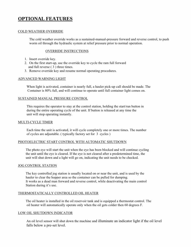
OPTIONAL FEATURES COLD WEATHER OVERRIDE The cold weather override works as a sustained-manual-pressure forward and reverse control, to push
worm oil through the hydraulic system at relief pressure prior to normal operation. OVERRIDE INSTRUCTIONS
1. Insert override key. 2. On the first start-up, use the override key to cycle the ram full forward
and full reverse ( 3 ) three times. 3. Remove override key and resume normal operating procedures.
ADVANCED WARNING LIGHT When light is activated, container is nearly full, a hauler pick-up call should be made. The Container is 80% full, and will continue to operate until full container light comes on. SUSTAINED MANUAL PRESSURE CONTROL This requires the operator to stay at the control station, holding the start/run button in during the entire operating cycle of the unit. If button is released at any time the unit will stop operating instantly. MULTI-CYCLE TIMER Each time the unit is activated, it will cycle completely one or more times. The number of cycles are adjustable. ( typically factory set for 3 cycles ) PHOTOELECTRIC START CONTROL WITH AUTOMATIC SHUTDOWN The photo eye will start the unit when the eye has been blocked and will continue cycling the unit until the eye is cleared. If the eye is not cleared after a predetermined time, the unit will shut down and a light will go on, indicating the unit needs to be checked. JOG CONTROL STATION The key controlled jog station is usually located on or near the unit, and is used by the hauler to clear the hopper area so the container can be pulled for dumping. It works as a dead man forward and reverse control, while deactivating the main control Station during it’s use. THERMOSTATICALLY CONTROLLED OIL HEATER The oil heater is installed in the oil reservoir tank and is equipped a thermostat control. The oil heater will automatically operate only when the oil gets colder then 60 degrees F. LOW OIL SHUTDOWN INDICATOR An oil level sensor will shut down the machine and illuminate an indicator light if the oil level falls below a pre-set level.

Revised 9-27-06
Crouzet Controller General Machine Set Up
Note: The following procedure is intended only for properly trained and authorized service
personnel. The controller, pressure switches, and relief cartridge are all factory set and are NOT user-operated controls.
1) PS-1 operates as both the “stop” pressure switch and the “full” pressure switch. This pressure switch must be plumbed into the pressure port such that it will see pressure both as the ram extends and as it retracts.
2) PS-2, if required, is the 80% light and may be plumbed into either the extend port or the pressure port.
3) To set the pressures: (Note: Both inputs and outputs are 120V)
a) Set the pressure switch to a high pressure and back the relief off to a low pressure. b) Power up and start the machine. The ram will bottom out on the retract stroke
and the pump will continue to run. c) Adjust the relief pressure to the intended full pressure. d) Slowly back off on the pressure switch until the motor either stops or the ram
starts to run forward. e) The pressure switch is now set. f) Adjust the reverse timer to a time in excess of the normal reverse time. (Push the
“A” button to access this screen. Push the “OK” button to enter editing mode. Use the up and down arrows to adjust the time. Push the “OK” button again to enter the new value.)
g) Start the machine. The ram will run all the way forward and bottom out. The full light (and 80% light if present) will come on and the machine will stop. (This double checks the full pressure setting and the functioning of the bulb)
h) If present, the 80% light can now be set by backing off the relief and once again starting the machine. Adjust the relief to the intended 80% pressure and restart the machine if necessary to bottom out the ram on the forward stroke. On the forward stroke only, adjust the 80% pressure switch till the 80% light comes on.
i) Disconnect the pressure switch wire and once again start the machine. j) After the ram bottoms out on either the forward or reverse stroke, adjust the relief
valve to the intended relief pressure. k) Re-attach the pressure switch wire. l) Set the reverse timer to the correct time.
Note on Operation: Once a safe stop condition occurs, the machine may only be started using the manual start push button or start key switch. Only after the machine is cycled once with the manual start will any optional auto-start circuit become active. Conditions that will cause a safe stop include e-stop, power failure, full pressure, interlock opening while ram is in motion, optional photo-eye blocked for excessive time, etc. Also, Multi-Cycle (if present) will be disabled for the first start after a safe stop.

Last Revised 9-27-06
Crouzet Program Operation AC4025274 & AC402987
Features: Multi-cycle, 100% light
• The machine will reverse after traveling forward for a factory preset period of time and detect the fully retracted home position by pressure.
• The controller is not an operator control. It is located inside the electrical control box and should
only be accessed or adjusted by properly trained and authorized service personnel.
• The multi-cycle will automatically cycle the machine a set number of cycles every time the machine is started except when following a “Safe Stop”. See “Safe Stop” below. The Multi-cycle counter is factory pre-set.
• The initial machine start after any “safe stop” shut down can only be accomplished by manually
pressing the start button. The multi-count start circuit will only become active after the machine has run the initial “return home” cycle.
• If the ram is stopped in any position other than the fully retracted position, then the start button
will only cause the ram to retract and stop. The start button will need to be pressed again in order to start a normal machine cycle.
• A “safe stop” shut down will occur if the e-stop is pressed, the key switch is turned off, power is
lost, or full pressure is achieved while the ram is in any other position besides the “home position” (fully retracted). A “Safe Stop” will also occur if the feed door is opened while the machine is cycling, or if the pressure switch fails (watch-dog timer)
• A “safe stop” condition will reset the multi-count back to zero.
• The multi-counter screen can be viewed by pressing button “B” on the controller face. This will
allow both the present count and the preset count to be viewed. Pressing the “OK” button while in this screen will enter the programming mode and allow the preset count to be adjusted with the up and down arrows. After the desired count is shown, press the “OK” button again to enter the count and update the program. Pressing “B” again will return to the main monitoring screen.
• The reverse timer is pre-set in the program from the factory. This setting may be viewed or
altered by pressing button “A” on the controller face. This will allow both the present time and the preset time to be viewed. Pressing the “OK” button while in this screen will enter the programming mode and allow the preset time to be adjusted with the up and down arrows. After the desired time is shown, press the “OK” button again to enter the count and update the program. Pressing “A” again will return to the main monitoring screen. Note: Time units are in 100 mille-second increments. IE 46.5 seconds is entered as 465 and 18 seconds is entered as 180.

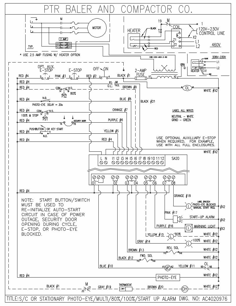
Revised 9-27-06 Photo-Eye Start
Program Operation AC402097x
Features: 100% light standard, 80% light optional, and Photo-eye start.
• The photo-eye will automatically start the machine each time it is blocked for the set time period. If the photo-eye is continuously blocked for this time period, the contact will close and send a signal to the controller. The warning light will flash continuously as long as the photo-eye start circuit is active. Note: For field changes, consult photo-eye documentation for setting the delay. The photo-eye is not a user operator control.
• Once the controller received the start signal from the either the photo-eye or the start
button, the audible alarm will sound for twenty seconds prior to the machine auto starting. If the photo-eye is uncovered during this time or the start button released, the machine will not start up. The audible alarm will stop sounding once the machine starts while the visible warning will continue to flash while the machine is running and while the photo-eye start circuit is active. Total delay of approximately 21 seconds.
• The initial machine start after any “safe stop” shut down can only be accomplished by
manually pressing the start button or turning the start key. The auto-start circuit will only become active after the machine has run the initial cycle.
• A “safe stop” shut down will occur if the e-stop is pressed, the key switch is turned off,
power is lost, full pressure is achieved, the feed door is opened while the machine is cycling, if the photo-eye remains blocked for more than the photo-eye blocked timer setting, if the first watch-dog timer detects a pressure switch or directional valve failure, if the machine runs continuously for more time than the second watchdog timer is set for, or other error condition occurs.
• To re-initialize the auto-start circuit, first clear the shut down condition. I.E. Pull the e-
stop out, restore power, close the feed door, etc. Then manually start the machine using the start push-button or key start switch. The “Photo-Eye Blocked / Manual Start Req.” light will blink to indicate that a manual start is required or will stay constantly lit if the Photo-Eye is blocked. The warning light will also stop flashing if the photo-eye start circuit becomes inactive. Note: The delay and alarm will be active even in the case of a manual start. The start button MUST be held in for 20 seconds before the machine will start. The machine will not start if the start button is released before this time.

Revised 9-27-06
The warning light and audible alarm must be audible and visible at the compactor. Also, a machine control such as a jog station or disconnect must be visible from the discharge end of the compactor.
Apply “This Machine Starts Automatically” label to the hopper at the photo-eye, to the front of the hopper so it is visible when the container is pulled (except TP-33 where container is manually pulled and the sticker on the side of the machine is clearly visible at the binder attachment), on the auxiliary clean out door if present, and on the security door if present (ship loose with security door stickers). A total of four is required except where two of the locations are close enough together that one sticker will suffice for both or if one of the options is not present. Note: For field install apply stickers to any of these locations where this sticker does not already exist.
Apply “Before Opening Door, Turn Control Panel Key to Off Position, Remove Key, and Block Off Trash Chute” label to the auxiliary clean out door on the hopper (if present).
Apply “Light On: Photo-Eye Blocked / Light Blinking: Manual Start Req.” label to the control panel at the photo-eye blocked light.
An interlock switch is required on all hopper loading doors.
No limit switches are required. Unit shifts from reverse to forward on pressure and from forward to reverse on a timer.
The controller is not a user operated control. It is located inside the control panel and should only be accessed or adjusted by properly trained and authorized service personnel.
The reverse timer can be set by pressing the “A” button on the front controller panel to access the reverse timer set up screen. Once in this screen hit the “OK” button to unlock the set value then use the up and down arrows to enter the desired timer setting. Press the “OK” button again to enter the new value. Note: This setting is in 1/10th seconds so 305 will actually be 30.5 seconds. Pushing the “A” button again will return to the main screen.


MAINTENANCE INSTRUCTIONS LOCKOUT PROCEDURES
1. All affected employees shall be notified that equipment must be shut down and locked
out prior to performing service or maintenance. 2. The equipment if operating, shall be shut down by normal means and the energy-
isolating device shall be deactivated to isolate the equipment from the energy source. Isolation shall include: a. Removing the key from the key-lock ON/OFF switch b. Installing a tag at the lockout station (disconnect) and on the compactor control
panel c. Placing operating equipment in such a position as not to be subject to possible
freefall and/or installing additional blocking devices to prevent freefall d. Relieving stored hydraulic or pneumatic pressure, after blocking devices are
installed 3. Equipment isolation shall be verified by activating the normal operating controls
insuring first that no personnel are exposed (insure operating controls are returned to the neutral or “OFF” position after verifying the isolation of the equipment).
4. When the servicing or maintenance is completed, only after checking that the equipment is ready to operate, insuring that the surrounding area is clear and that employees are safely positioned or removed from the area and verifying that controls are in neutral, shall the lockout devices be removed and the equipment be re-energized.
5. Affected employees shall be notified that the servicing or maintenance has been completed and the equipment is ready for use.
6. See also OSHA 29 CFR 1910.147 Appendix A .
CLEAN OUT PROCEDURES
The authorized service technician performing “Clean Out” work on the Self-Contained and Stationary Compactor must follow the LOCKOUT PROCEDURE described above.
ACCESS COVER
When access covers are removed for any reason, follow “LOCKOUT PROCEDURES" as described above, with the fuses removed by a qualified person. When replacing access covers, caulk all edges to ensure liquid tight seal.
CONFINED SPACE
Use lockout procedure prior to entry onto CHUTE, DOGHOUSE, HOPPER, or CYLINDER AREA of this unit.

Safety And Periodic Maintenance Inspection Only periodic maintenance is required to keep your compactor in top operating order. Maintain oil level so that it rests half way in gauge on the side of tank when ram is fully extended. The self-contained unit does require lubrication and should be greased every 90 days. The 3/16” grease fittings require ultra light URN MDEP or equal grease and can be found:
a. In end of all roller axles b. In end of all wheel axles c. Center of all cylinder mount tubes d. In rear door hinge tubes
It is recommended that the cylinder area of your compactor be cleaned twice a year (Spring and Fall). At this time a full safety inspection of entire unit should be performed. After cleaning, check hoses for wear, check cylinders and all hydraulic fittings for oil leaks. Check functionality of all safety interlocks switches and other protective devices daily. Perform full safety inspection of entire unit at least once a year. Be sure to reseal rear panel with Form A Gasket No.2 Sealant or equal on self-contained units. First remove all of the old sealant residue, and then apply a new continuous bead of Gasket No. 2 Sealant to the inside outer edge of the rear panel before bolting it back in place.
Replace Fuses Always replace blown fuses with proper amp fuses. After replacing a fuse, always observe operation in an effort to determine what caused the fuse to blow. Refer to Electrical Installation Sheet for size of power fuses. Oil Change Over a period of time the oil will become contaminated from dirt and dust. Therefore, it is recommended that the oil be changed every two to three years. At this time, the suction strainer should be removed and cleaned. If the area around the compactor is particularly dirty and dusty, the reservoir should be drained, the cover removed and the bottom of the reservoir should be thoroughly cleaned about once every three years. Low temperature oil (5w-20) may be used in areas of the country subject to cold winters. Depending on the severity of the cold weather this oil can be used on its own or in conjunction with an oil heater. Note: The power unit will be marked to indicate low temperature oil if it is factory filled with this type of oil. It is recommended that low temperature oil be changed every one to two years.


DOGHOUSE ON UNITS
With this method the refuse is fed through a doghouse located over the charging opening. A. Disconnect - the mainline disconnect switch must be located either on the compactor
or on a wall adjacent to the compactor, but in no case more than 15’ from the charging opening and always within view of an operator feeding the compactor.
The control station including the Emergency Stop Button must be located within 3’ of the doghouse charging opening so that the operator can operate the controls and at the same time see the entire operation.
Warning Decals and Instruction Plates
Read and follow the warning instructions of each decal, it is for the operators’ safety that each decal is in place. Make certain that each decal is obeyed at all times. Notify the proper authority of any missing decal. Replacements can be ordered from:
PTR Baler and Compactor Company 2207 E. Ontario Street Philadelphia, PA 19134
(800) 523-3654 (800) 523-1155 (215) 533-5100
(215) 537-8536 - Fax


WARRANTY PTR BALER AND COMPACTOR COMPANY warrants that all new machinery and equipment manufactured, and sold, by it, except as hereinafter set forth, when operated, maintained and installed, and used in normal service and in accordance with provisions of the operator’s manual in which this warranty is expressly included and made a part of, that for a period of three hundred sixty-five (365) days from and after the date of installation, said equipment, in whole or in part, will be free from defects in material and workmanship. The responsibility of PTR BALER AND COMPACTOR COMPANY, under this warranty to the purchaser, except as to title, shall not in any case exceed the cost of correcting defects in the equipment of part thereof, except as hereinafter set forth. Warranty repair or replacements shall not extend in any instance beyond the initial warranty period. PTR BALER AND COMPACTOR COMPANY shall under no circumstances be responsible for any loss of business or profit to the purchaser or any other consequential damages in connection with the sale of such equipment or any obligation under this warranty. The foregoing shall constitute the sole remedy of the purchaser, and the responsibility of PTR BALER AND COMPACTOR COMPANY. Warranty repairs and/or replacements (at our option), will be made for both parts and labor. The authorized service center must use PTR BALER AND COMPACTOR authorized parts. Labor will be allowed at a maximum of thirty ($40.) hourly rate. Premium rates will be at the customer’s accountability. All parts, components or accessories requiring repair or replacement, within the warranty period, shall be returned PREPAID, to the PTR BALER AND COMPACTOR COMPANY at the expense of the buyer, lessee, or consignee. The PTR BALER AND COMPACTOR COMPANY will return at its expense replacement parts, components or accessories found to be defective. Shipment of parts under warranty shall be made via United Parcel Service or Parcel Post. Cost of any other means or transportation shall be paid by the equipment user. PTR BALER AND COMPACTOR COMPANY does not assume any responsibility of liability for improper use of the equipment or improper installation of any unit, part or accessory which may cause damage to the unit. The installation of parts or accessories manufactured or sold by any other supplier shall be deemed to void all warranties. Warranty claims for equipment will not be processed unless a properly completed and signed warranty card (attached to the installation checklist) has been received. NOTE: Always have Serial Number and Model Number of unit ready when calling for service
NON-WARRANTABLE REPAIRS 1. Adjustments required as the result of routine operations; limit switches, pressure switch. relief valve. 2. Tightening of hydraulic fittings and terminal connections 3. Electrical fuses (Tripped overloads or breakers, etc.) 4. Power to the unit (Changing phase, motor rotation, or damage by customer hooking-up electric, etc.) 5. Addition of hydraulic oil 6. Repairs necessitated by improper use, failure to follow instructions, and abuse of the equipment 7. Proper authorization from PTR Baler and Compactor Company 8. Operator error (door not closed and /or latched etc.) 9. Damage or error from hauler 10. Installer error, and/or customer site problems at time of installation.

Some more common replacement parts
PTR Number Description500196 C4 Control Valve155529 C7 Control Valve603198 Contactor, 22A603196 Contactor, 40A603200 Contactor, 75A603520 Fuse, 1.5A Time-Delay320209 Fuse, 2 amp 250V500528 Fuse, 2 amp 600V155408 Key, On/Off Switch320046 Limit Switch320045 Limit Switch Arm603199 Overload, 20A603197 Overload, 40A603201 Overload, 80A500515 Pressure Switch155393 Relay base, 11-pin155392 Relay, 11-pin602391 Relay, Programmable500041 Safety Interlock500822 Safety Interlock HD only630223 Service Manual500555 Timer


