compaq dlt user guide - ge janssengejanssen.com/howto/dlt2000/dlt_install_guide.pdfcompaq dlt user...
TRANSCRIPT
Compaq DLT User GuideUser Guide
Second Edition (March 1998)Part Number 185292-002Compaq Computer Corporation
. . . . . . . . . . . . . . . . . . . . . . . . . . . . . .
C
Writer: Jim Belew Project: Compaq DLT Drive User Guide Comments:File Name:A-NOTICE.DOC Last Saved On:3/13/97 7:36 AM
NOTICE
The information in this publication is subject to change without notice.
COMPAQ COMPUTER CORPORATION SHALL NOT BE LIABLE FOR TECHNICAL OREDITORIAL ERRORS OR OMISSIONS CONTAINED HEREIN, NOR FOR INCIDENTAL ORCONSEQUENTIAL DAMAGES RESULTING FROM THE FURNISHING, PERFORMANCE, ORUSE OF THIS MATERIAL.
This publication contains information protected by copyright. No part of this publication may bephotocopied or reproduced in any form without prior written consent from Compaq ComputerCorporation.
The software described in this guide is furnished under a license agreement or non disclosureagreement. The software may be used or copied only in accordance with the terms of the agreement.
This publication does not constitute an endorsement of the product or products that were tested. Theconfiguration or configurations tested or described may or may not be the only available solution. Thistest is not a determination of product quality or correctness, nor does it ensure compliance with anyfederal, state, or local requirements. Compaq does not warrant products other than its own strictly asstated in Compaq product warranties.
Product names mentioned herein may be trademarks and/or registered trademarks of their respectivecompanies.
1997 Compaq Computer Corporation.All rights reserved. Printed in the U.S.A.
Compaq, Compaq Insight Manager, and SmartStart,Registered United States Patent and Trademark Office.
ProLiant, ProSignia, and Systempro/XL are trademarks of Compaq Computer Corporation.
Microsoft and Windows are registered trademarks of Microsoft Corporation.Windows NT and Windows 95 are trademarks of Microsoft Corporation.
Compaq DLT Drive User Guide
Second Edition (March 1997)Part Number 185292-002
. . . . . . . . . . . . . . . . . . . . . . . . . . . . . .iii
Compaq DLT Drive User Guide
Writer: Jim Belew Project: Table of Contents Comments: 185292.002 Final
File Name:B-TOC.DOC Last Saved On:6/26/98 9:43 AM
Contents
Preface
About This Guide
How This Guide is Organized..................................................................................vii
Conventions Used in This Guide.............................................................................viii
Symbols on Equipment...........................................................................................viii
General Warnings and Cautions................................................................................ ix
Chapter 1Overview
Tape Formats ..........................................................................................................1-1
Data Compression...................................................................................................1-1
SCSI-2 Controller Requirements.............................................................................1-2
Chapter 2Installing an Internal DLT Drive
SCSI-2 Controller Requirements.............................................................................2-1
Software and Tool Requirements.............................................................................2-1
Setting the SCSI ID.................................................................................................2-2
Preparing the Server ...............................................................................................2-3
Installing the DLT Drive.........................................................................................2-4
Reassembling the Server.........................................................................................2-5
Completing the Installation.....................................................................................2-6
. . . . . . . . . . . . . . . . . . . . . . . . . . . . . .iv
Writer: Jim Belew Project: Table of Contents Comments: 185292.002 Final
File Name:B-TOC.DOC Last Saved On:3/13/97 7:36 AM
Chapter 3Connecting an External DLT Drive
Preparing the Drive.................................................................................................3-1
SCSI-2 Controller Requirements.............................................................................3-2
Setting the SCSI ID.................................................................................................3-2
Connecting the Drive ..............................................................................................3-4
Daisy Chaining .......................................................................................................3-5
Daisy-Chaining Storage Devices Together........................................................3-5
Chapter 4Installing the Software Drivers
Device Drivers........................................................................................................4-1
NetWare.................................................................................................................4-2
ASPI Support..........................................................................................................4-3
Microsoft Windows NT...........................................................................................4-5
Microsoft Windows 95............................................................................................4-6
SCO UNIX.............................................................................................................4-7
UnixWare...............................................................................................................4-8
OS/2.......................................................................................................................4-9
Banyan VINES.....................................................................................................4-10
Chapter 5Operating the DLT Drive
Front Panel .............................................................................................................5-1
Front Panel Indicators.............................................................................................5-3
Front Panel Controls ...............................................................................................5-5
Power-On Self-Test (POST)....................................................................................5-6
Loading and Unloading a Tape Cartridge...............................................................5-6
Selecting Drive Density...........................................................................................5-8
Density Select Example....................................................................................5-9
. . . . . . . . . . . . . . . . . . . . . . . . . . . . . .v
Compaq DLT Drive User Guide
Writer: Jim Belew Project: Table of Contents Comments: 185292.002 Final
File Name:B-TOC.DOC Last Saved On:3/13/97 7:36 AM
Operating the DLT Drive continued
Tape Cartridge Write-Protect Switch.....................................................................5-10
Cartridge Compatibility ........................................................................................5-11
Cartridge Handling and Storage............................................................................5-11
Chapter 6Tape Drive Cleaning
Chapter 7Troubleshooting
Updating the Firmware on the DLT TapeDrive ................................................7-3
Interpreting the Results of Firmware Update....................................................7-5
Appendix APower Cord Set Requirements
General Requirements...........................................................................................A-1
Country-Specific Requirements..............................................................................A-2
Appendix BElectrostatic Discharge
Preventing Electrostatic Damage........................................................................... B-1
Grounding Methods .............................................................................................. B-1
Appendix CGetting Help
Compaq Web Site................................................................................................. C-1
Telephone Numbers.............................................................................................. C-1
. . . . . . . . . . . . . . . . . . . . . . . . . . . . . .vi
Writer: Jim Belew Project: Table of Contents Comments: 185292.002 Final
File Name:B-TOC.DOC Last Saved On:3/13/97 7:36 AM
Appendix DSupplemental Information About SCO UNIX
Configuration Requirements .................................................................................D-1
Appendix ERegulatory Compliance Notices
Federal Communications Commission Notice....................................................... E-1
Modifications................................................................................................. E-1
Cables............................................................................................................ E-2
Canadian Notice (Avis Canadien) ......................................................................... E-2
Class B Equipment......................................................................................... E-2
European Union Notice......................................................................................... E-2
Japanese Notice..................................................................................................... E-3
Index
. . . . . . . . . . . . . . . . . . . . . . . . . . . . . .vii
Compaq DLT Drive User Guide
Writer: Jim Belew Project: About This Guide Comments: 185292.002 final
File Name:C-PREF.DOC Last Saved On:3/13/97 7:35 AM
Preface
About This Guide
This user guide provides information for installing, configuring, operating andcleaning the Compaq DLT Drive. For instructions on using the DLT Drive,please refer to the manual that came with your drive.
How This Guide is OrganizedChapter 1, “Introduction,” provides an overview of the DLT Drive andinstallation requirements.
Chapter 2, “Installing an Internal DLT Drive,” provides instructions for theinstallation of the Compaq DLT Drive in Compaq servers.
Chapter 3, “Connecting an External DLT Drive,” provides instructions for theinstallation of the Compaq DLT Drive as an external unit.
Chapter 4, “Installing the Software Drivers,” covers procedures for theinstallation of software drivers to complete the drive installation.
Chapter 5, “Tape Drive Operations,” provides instructions for operating theDLT Drive efficiently.
Chapter 6, “Tape Drive Cleaning,” describes the cleaning procedure.
Chapter 7, “Troubleshooting,” provides suggestions for problem solvingbefore and after tape drive installation.
Appendix A,“Power Cord Requirements,” provides the power cordset requirements.
Appendix B, “Electrostatic Discharge,” provides information on avoidingelectrostatic damage and suggestions for grounding methods.
Appendix C, “Getting Help,” has additional information on the CompaqForum of CompuServe and QuickFind.
Appendix D, “Supplemental Information About SCO UNIX,” covers SCOUNIX configuration requirements and using Legato under SCO UNIX.
Appendix E, “Regulatory Compliance Notices,” contains the compliancestatements from the various worldwide agencies regulating this product.
. . . . . . . . . . . . . . . . . . . . . . . . . . . . . .viii About This Guide
Writer: Jim Belew Project: About This Guide Comments: 185292.002 final
File Name:C-PREF.DOC Last Saved On:3/13/97 7:35 AM
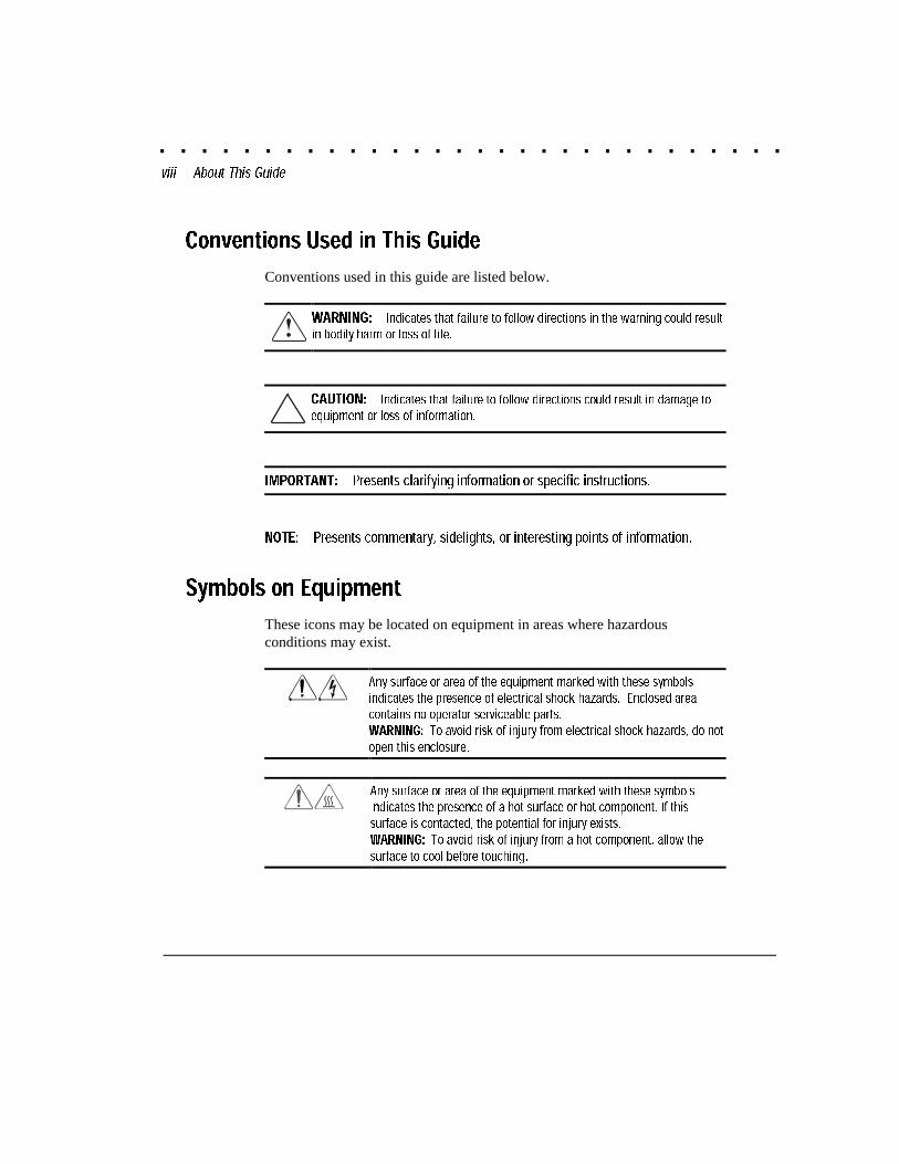
Conventions Used in This Guide
Conventions used in this guide are listed below.
WARNING: Indicates that failure to follow directions in the warning could resultin bodily harm or loss of life.
CAUTION: Indicates that failure to follow directions could result in damage toequipment or loss of information.
IMPORTANT: Presents clarifying information or specific instructions.
NOTE: Presents commentary, sidelights, or interesting points of information.
Symbols on Equipment
These icons may be located on equipment in areas where hazardousconditions may exist.
Any surface or area of the equipment marked with these symbolsindicates the presence of electrical shock hazards. Enclosed areacontains no operator serviceable parts.WARNING: To avoid risk of injury from electrical shock hazards, do not
open this enclosure.
Any surface or area of the equipment marked with these symbolsindicates the presence of a hot surface or hot component. If thissurface is contacted, the potential for injury exists.WARNING: To avoid risk of injury from a hot component, allow the
surface to cool before touching.
. . . . . . . . . . . . . . . . . . . . . . . . . . . . . .ix
Compaq DLT Drive User Guide
Writer: Jim Belew Project: About This Guide Comments: 185292.002 finalFile Name:C-PREF.DOC Last Saved On:3/13/97 7:35 AM
General Warnings and Cautions
WARNING: Compaq ProLiant 2000, 4000, 4500 and 5000 are capableof producing energy levels that are considered hazardous. Users shouldnot remove enclosures nor should they bypass the interlocks provided forremoval of these hazardous conditions.
Installation of accessories and options in areas other than front hot plugbays should be performed by individuals who are both qualified in theservicing of computer equipment and trained in the hazards associatedwith products capable of producing hazardous energy levels.
WARNING: To reduce the risk of personal injury from hot surfaces,allow the internal system components to cool before touching them.
WARNING: To reduce the risk of electric shock or damage to theequipment:
■ Do not disable the power cord grounding plug. The grounding plug isan important safety feature.
■ Plug the power cord into a grounded (earthed) electrical outlet that iseasily accessible at all times.
Disconnect power from the product by unplugging the power cord fromeither the electrical outlet or the computer or other product
. . . . . . . . . . . . . . . . . . . . . . . . . . . . . .x About This Guide
Writer: Jim Belew Project: About This Guide Comments: 185292.002 finalFile Name:C-PREF.DOC Last Saved On:3/13/97 7:35 AM
WARNING: To reduce the risk of electric shock or damage to theequipment:
■ Do not place anything on power cords or cables. Arrange them so thatno one may accidentally step or trip over them.
■ Do not pull on a cord or cable. When unplugging from the electricaloutlet, grasp the cord by the plug.
CAUTION: Placing a hand or object other than a tape cartridge into theDLT Drive may damage the tape drive.
. . . . . . . . . . . . . . . . . . . . . . . . . . . . . .1-1
Compaq DLT Drive User Guide
Writer: Jim Belew Project: Overview Comments: 185292.002 final
File Name:D-CH1.DOC Last Saved On:3/13/97 7:35 AM
Chapter 1
Overview
This chapter provides information on tape formats, data compression, andsystem and controller requirements for all Compaq DLT Drives and formats.
For information on tape software, refer to the “readme” card enclosed with thedrive. More information may also be obtained by accessing the Compaq WebSite on the Internet at http://www. compaq.com.
Tape Formats
The Compaq DLT Drive is a high-capacity, high-performance streaming tapedrive designed for use with Compaq servers. The DLT Drive is a full-heighttape drive with a 5-1/4-inch form factor. The DLT Drive has a multi-channelread/write head, utilizes a Digital Lempel-Ziv (DLZ) high efficiency datacompression algorithm, and has a filing system to maximize data andminimize data access time.
The DLT Drive uses a half-inch tape cartridge compatible with the DLT Tape,DLT Tape II, DLT Tape III, DLT Tape IIIXT and DLT Tape IV..
Data Compression
The DLT Drive reads and writes both uncompressed (native) and DLZcompressed data. The 15/30 DLT model features a native formatted capacity of15 gigabytes and a sustained native data transfer rate of 1.25 megabytes persecond (MB/s). The 35/70 DLT model has a native formatted capacity of35 gigabytes and a sustained native data transfer rate of 5.0 MB/s.
When operating in compressed mode, data capacity is affected by how muchthe data can be compressed. Most data can be compressed at an approximate2:1 ratio. For instance, data compressed at a 2:1 ratio would provide a totaldrive capacity of 30 GB for the 15/30 DLT Drive and 70 GB for the 35/70DLT Drive.
. . . . . . . . . . . . . . . . . . . . . . . . . . . . . .1-2 Overview
Writer: Jim Belew Project: Overview Comments: 185292.002 final
File Name:D-CH1.DOC Last Saved On:3/13/97 7:35 AM
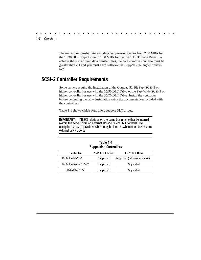
The maximum transfer rate with data compression ranges from 2.50 MB/s forthe 15/30 DLT Tape Drive to 10.0 MB/s for the 35/70 DLT Tape Drive. Toachieve these maximum data transfer rates, the data compression ratio must begreater than 2:1 and you must have software that supports the higher transferrate.
SCSI-2 Controller Requirements
Some servers require the installation of the Compaq 32-Bit Fast-SCSI-2 orhigher controller for use with the 15/30 DLT Drive or the Fast-Wide SCSI-2 orhigher controller for use with the 35/70 DLT Drive. Install the controllerbefore beginning the drive installation using the documentation included withthe controller.
Table 1-1 shows which controllers support DLT drives.
IMPORTANT: All SCSI devices on the same bus must either be internal(within the server) or in an external storage device, but not both. Theexception is a CD-ROM drive which may be internal when other devices areexternal or vice versa.
Table 1-1Supporting Controllers
Controller 15/30 DLT Drive 35/70 DLT Drive
32-Bit Fast-SCSI-2 Supported Supported (not recommended)
32-Bit Fast-Wide SCSI-2 Supported Supported
Wide-Ultra SCSI Supported Supported
. . . . . . . . . . . . . . . . . . . . . . . . . . . . . .2-1
Compaq DLT Drive User Guide
Writer: Jim Belew Project: Installing an Internal DLT Drive Comments: 185292.002 finalFile Name:E-CH2.DOC Last Saved On:3/13/97 7:35 AM
Chapter 2
Installing an InternalDLT Drive
This chapter describes the procedure to install a Compaq DLT Drive in aCompaq Server.
Installation involves the following steps:
■ Setting the SCSI ID
■ Preparing the server
■ Installing the DLT Drive
■ Reassembling the server
■ Completing the installation
SCSI-2 Controller Requirements
It is recommended that the server be equipped with a 32-Bit Fast-SCSI-2 orhigher controller for a 10/15 or 15/30-GB DLT Drive.
A 32-Bit Fast-Wide SCSI Controller is recommended for the 35/70-GB DLTDrive.
Software and Tool Requirements
The following items are required for Compaq DLT Tape Drive installation:
■ Torx-T15 screwdriver
■ Compaq SmartStart and Support Software CD
. . . . . . . . . . . . . . . . . . . . . . . . . . . . . .2-2 Installing an Internal DLT Drive
Writer: Jim Belew Project: Installing an Internal DLT Drive Comments: 185292.002 finalFile Name:E-CH2.DOC Last Saved On:3/13/97 7:35 AM
Setting the SCSI ID
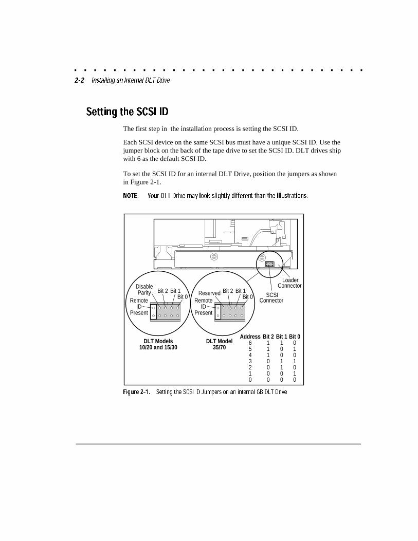
The first step in the installation process is setting the SCSI ID.
Each SCSI device on the same SCSI bus must have a unique SCSI ID. Use thejumper block on the back of the tape drive to set the SCSI ID. DLT drives shipwith 6 as the default SCSI ID.
To set the SCSI ID for an internal DLT Drive, position the jumpers as shownin Figure 2-1.
NOTE: Your DLT Drive may look slightly different than the illustrations.
DLT
3-00
5.EP
S
SCSIConnector
LoaderConnector
RemoteID
Present
Bit 2DisableParity
DLT Models10/20 and 15/30
Bit 1Bit 0
RemoteID
Present
Bit 2Reserved
DLT Model35/70
Bit 1Bit 0
Bit 21110000
Bit 11001100
Address6543210
Bit 00101010
Figure 2-1. Setting the SCSI ID Jumpers on an internal GB DLT Drive
. . . . . . . . . . . . . . . . . . . . . . . . . . . . . .2-3
Compaq DLT Drive User Guide
Writer: Jim Belew Project: Installing an Internal DLT Drive Comments: 185292.002 finalFile Name:E-CH2.DOC Last Saved On:3/13/97 7:35 AM
Preparing the Server
To prepare the server:
1. Perform a normal system shutdown according to your network andoperating system requirements.
2. Turn OFF the server and then all peripheral devices.
3. Disconnect the AC power cord from the outlet, then from the server andall peripheral devices.
CAUTION: Electrostatic discharge (ESD) can damage electroniccomponents. Be sure you are properly grounded before beginning thisprocedure. See Appendix B, �Electrostatic Discharge,� for furtherinformation.
. . . . . . . . . . . . . . . . . . . . . . . . . . . . . .2-4 Installing an Internal DLT Drive
Writer: Jim Belew Project: Installing an Internal DLT Drive Comments: 185292.002 finalFile Name:E-CH2.DOC Last Saved On:3/13/97 7:35 AM
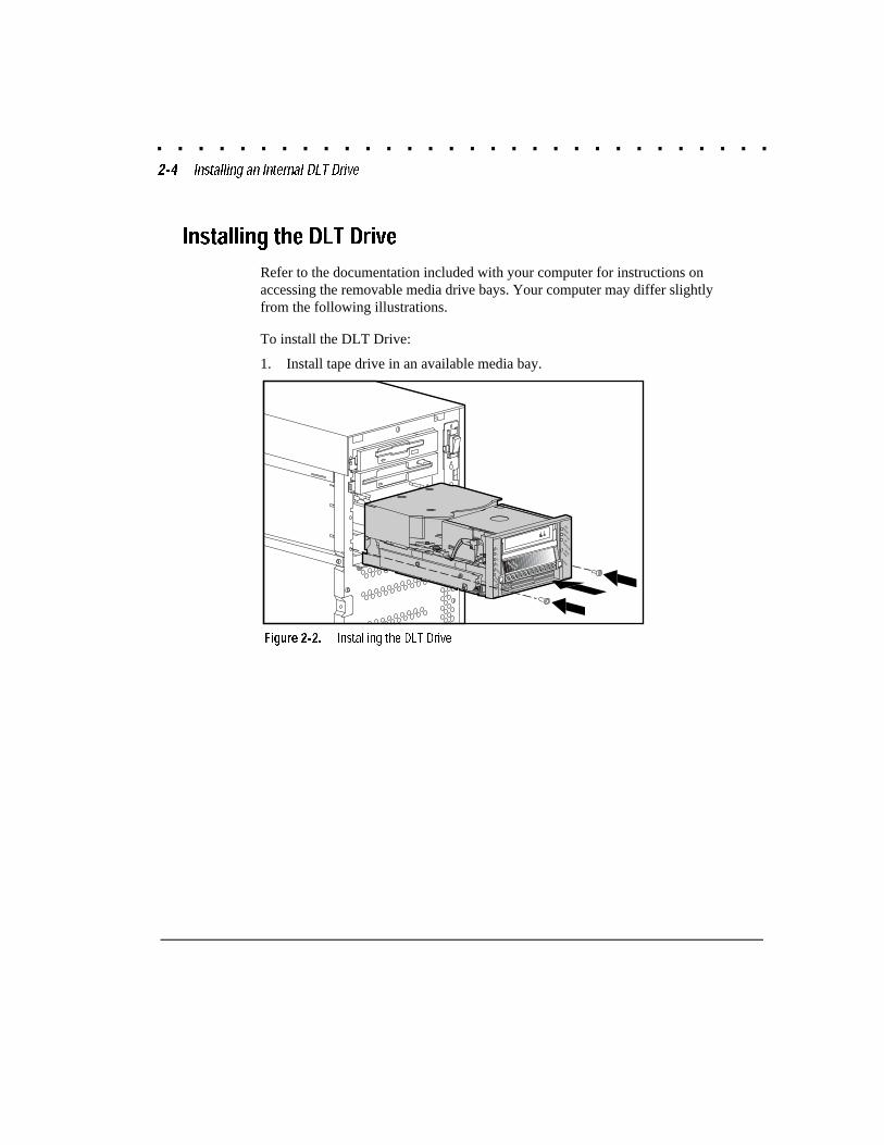
Installing the DLT Drive
Refer to the documentation included with your computer for instructions onaccessing the removable media drive bays. Your computer may differ slightlyfrom the following illustrations.
To install the DLT Drive:
1. Install tape drive in an available media bay.
DLT_059.EPS
WriteProtectedTape in UseUseCleaning TapeOperateHandle
DensityOverideDensitySelect
6.0
15.0
30.0
Compress
2.6
Unload
Figure 2-2. Installing the DLT Drive
. . . . . . . . . . . . . . . . . . . . . . . . . . . . . .2-5
Compaq DLT Drive User Guide
Writer: Jim Belew Project: Installing an Internal DLT Drive Comments: 185292.002 finalFile Name:E-CH2.DOC Last Saved On:3/13/97 7:35 AM
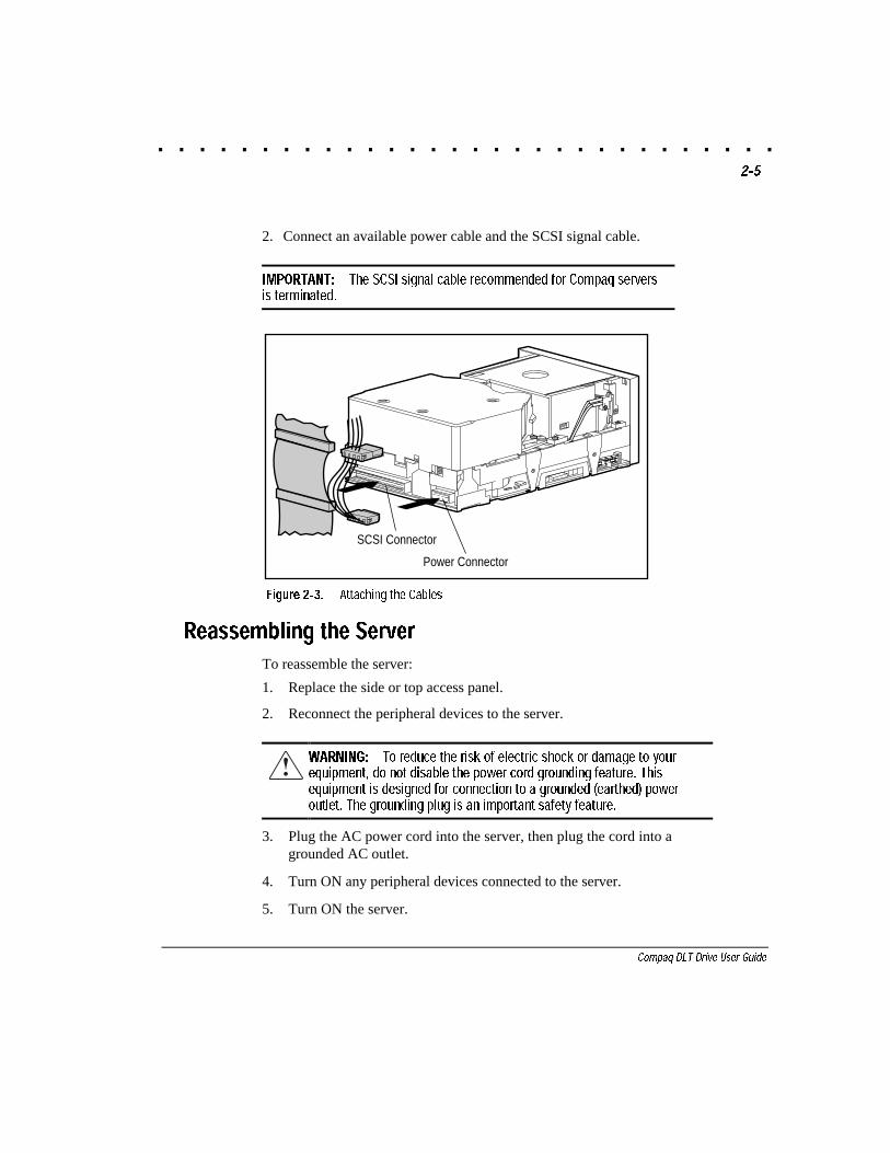
2. Connect an available power cable and the SCSI signal cable.
IMPORTANT: The SCSI signal cable recommended for Compaq serversis terminated.
DLT_039.EPS
Power Connector
SCSI Connector
Figure 2-3. Attaching the Cables
Reassembling the Server
To reassemble the server:
1. Replace the side or top access panel.
2. Reconnect the peripheral devices to the server.
WARNING: To reduce the risk of electric shock or damage to yourequipment, do not disable the power cord grounding feature. Thisequipment is designed for connection to a grounded (earthed) poweroutlet. The grounding plug is an important safety feature.
3. Plug the AC power cord into the server, then plug the cord into agrounded AC outlet.
4. Turn ON any peripheral devices connected to the server.
5. Turn ON the server.
. . . . . . . . . . . . . . . . . . . . . . . . . . . . . .2-6 Installing an Internal DLT Drive
Writer: Jim Belew Project: Installing an Internal DLT Drive Comments: 185292.002 finalFile Name:E-CH2.DOC Last Saved On:3/13/97 7:35 AM
Completing the Installation
Follow the procedure in Chapter 4, “Installing the Software Drivers,” to installthe driver supported by your operating system.
. . . . . . . . . . . . . . . . . . . . . . . . . . . . . .3-1
Compaq DLT Drive User Guide
Writer: Jim Belew Project: Connecting an External DLTDrive Comments: 185292.002 FinalFile Name:F-CH3.DOC Last Saved On:3/13/97 7:33 AM
Chapter 3
Connecting an ExternalDLT Drive
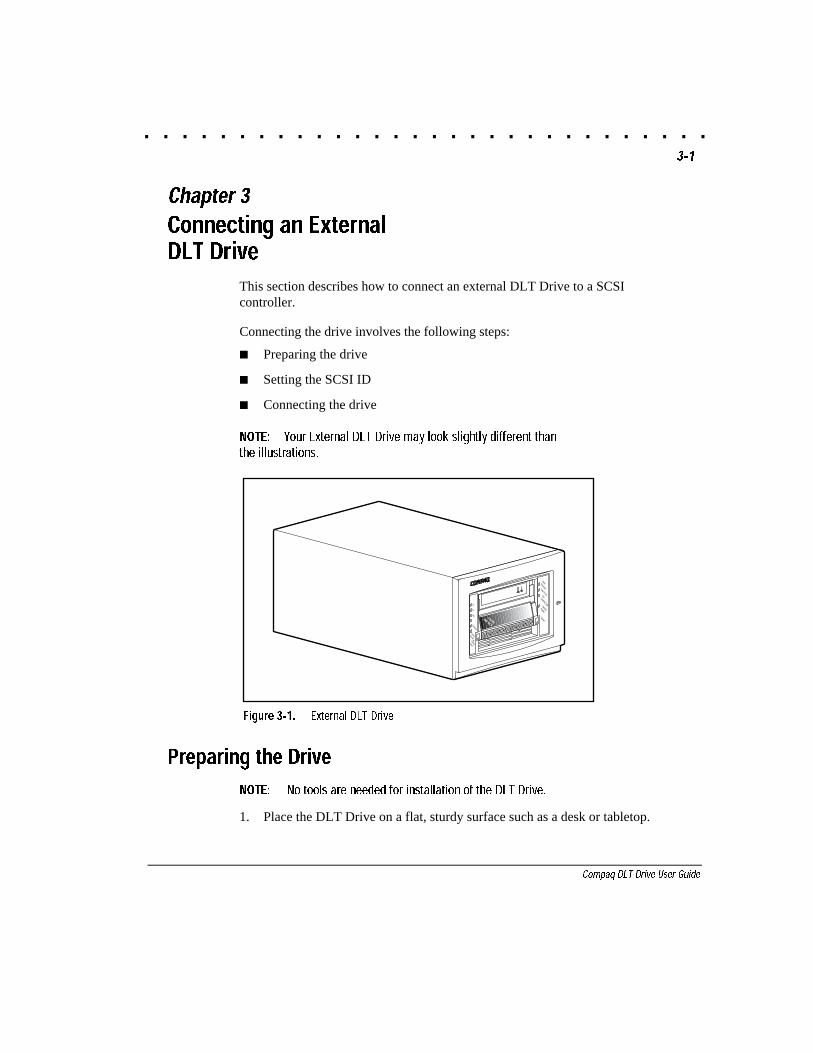
This section describes how to connect an external DLT Drive to a SCSIcontroller.
Connecting the drive involves the following steps:
■ Preparing the drive
■ Setting the SCSI ID
■ Connecting the drive
NOTE: Your External DLT Drive may look slightly different thanthe illustrations.
DLT_001.EPS
WriteProtectedTape in UseUseCleaning TapeOperateHandle6.0
15.0
Compress
DensityOverideDensitySelect
Unload
2.6
Figure 3-1. External DLT Drive
Preparing the Drive
NOTE: No tools are needed for installation of the DLT Drive.
1. Place the DLT Drive on a flat, sturdy surface such as a desk or tabletop.

. . . . . . . . . . . . . . . . . . . . . . . . . . . . . .3-2 Connecting an External DLTDrive
Writer: Jim Belew Project: Connecting an External DLTDrive Comments: 185292.002 Final
File Name:F-CH3.DOC Last Saved On:3/13/97 7:33 AM
NOTE: Do not place the unit on the floor. Allow enough space for properventilation and easy access to the front and rear of the DLT Drive. Allow atleast 3 inches (7.6 cm) between rear of unit and wall.
2. Check the SCSI ID.
NOTE: The drive is factory set to SCSI ID 6.
SCSI-2 Controller Requirements
It is recommended that the server be equipped with a 32-Bit Fast-SCSI-2 orhigher Controller for a 10/20-GB DLT or 15/30-GB DLT Drive.
A 32-Bit Fast-Wide SCSI-2 or higher controller is recommended for the35/70-GB DLT Drive.
IMPORTANT: All SCSI devices on the same bus must either be internal (within theserver) or in an external storage device, but not both. The exception is a CD-ROM drivewhich may be internal when other devices are external or vice versa.
Setting the SCSI ID
Each SCSI device on the same SCSI bus must have a unique SCSI ID. Youmust avoid duplicating SCSI ID when assigning the ID for the DLT Drive.Using the factory-set SCSI ID with Compaq storage devices is an effective wayto prevent ID duplication. The DLT Drive ships with 6 as the defaultSCSI ID.
WARNING: Risk of electrical shock. Do not attempt to open thisproduct. There are no user serviceable parts inside. Refer allservice to an Authorized Service Provider.
!
. . . . . . . . . . . . . . . . . . . . . . . . . . . . . .3-3
Compaq DLT Drive User Guide
Writer: Jim Belew Project: Connecting an External DLTDrive Comments: 185292.002 FinalFile Name:F-CH3.DOC Last Saved On:3/13/97 7:33 AM
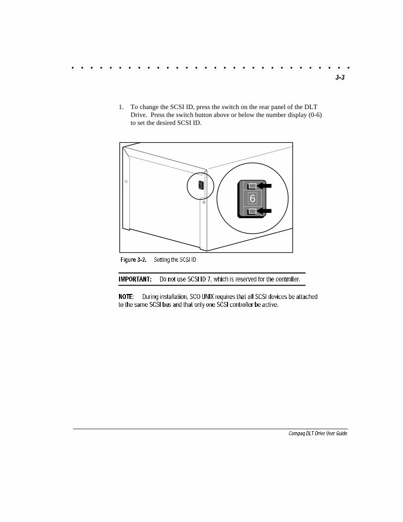
1. To change the SCSI ID, press the switch on the rear panel of the DLTDrive. Press the switch button above or below the number display (0-6)to set the desired SCSI ID.
DLT-004.EPS
0
6
Figure 3-2. Setting the SCSI ID
IMPORTANT: Do not use SCSI ID 7, which is reserved for the controller.
NOTE: During installation, SCO UNIX requires that all SCSI devices be attachedto the same SCSI bus and that only one SCSI controller be active.
. . . . . . . . . . . . . . . . . . . . . . . . . . . . . .3-4 Connecting an External DLTDrive
Writer: Jim Belew Project: Connecting an External DLTDrive Comments: 185292.002 Final
File Name:F-CH3.DOC Last Saved On:3/13/97 7:33 AM
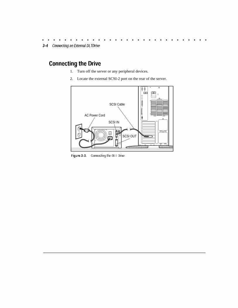
Connecting the Drive1. Turn off the server or any peripheral devices.
2. Locate the external SCSI-2 port on the rear of the server.
DLT_003.EPS
SCSI Cable
AC Power Cord
SCSI OUTI
0
0
SCSI IN
Figure 3-3. Connecting the DLT Drive
. . . . . . . . . . . . . . . . . . . . . . . . . . . . . .3-5
Compaq DLT Drive User Guide
Writer: Jim Belew Project: Connecting an External DLTDrive Comments: 185292.002 FinalFile Name:F-CH3.DOC Last Saved On:3/13/97 7:33 AM
3. Attach the SCSI signal cable to one of the SCSI connectors located onthe rear panel of the DLT drive and then to the external SCSI-2 port onthe server.
NOTE: A wide SCSI signal cable and a narrow SCSI signal cable have beenincluded with this drive option kit. Select the cable that matches the SCSIconnector on the rear of your server.
4. Snap the wire cable clamps into place to secure the cable to theconnector.
WARNING: To reduce the risk of electric shock or damage to yourequipment, do not disable the power cord grounding feature. Thisequipment is designed for connection to a grounded (earthed) poweroutlet. The grounding plug is an important safety feature.
5. Plug the drive's AC power cord first into the drive and then into agrounded AC outlet.
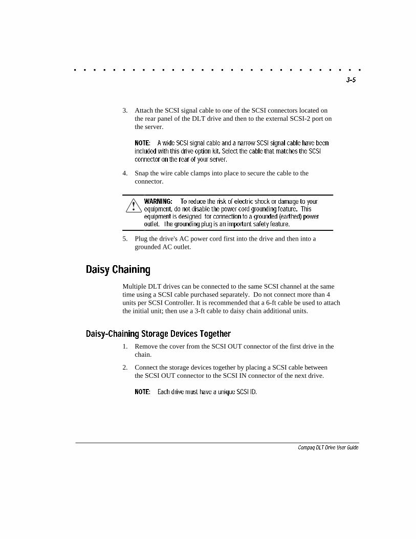
Daisy Chaining
Multiple DLT drives can be connected to the same SCSI channel at the sametime using a SCSI cable purchased separately. Do not connect more than 4units per SCSI Controller. It is recommended that a 6-ft cable be used to attachthe initial unit; then use a 3-ft cable to daisy chain additional units.
Daisy-Chaining Storage Devices Together
1. Remove the cover from the SCSI OUT connector of the first drive in thechain.
2. Connect the storage devices together by placing a SCSI cable betweenthe SCSI OUT connector to the SCSI IN connector of the next drive.
NOTE: Each drive must have a unique SCSI ID.
. . . . . . . . . . . . . . . . . . . . . . . . . . . . . .3-6 Connecting an External DLTDrive
Writer: Jim Belew Project: Connecting an External DLTDrive Comments: 185292.002 Final
File Name:F-CH3.DOC Last Saved On:3/13/97 7:33 AM
I
0
0
I
0
0
DLT_004.EPS
SCSI IN
SCSI OUT
SCSI IN
SCSI OUT
Figure 3-4. Daisy-chaining SCSI storage devices
. . . . . . . . . . . . . . . . . . . . . . . . . . . . . .4-1
Compaq DLT Drive User Guide
Writer: Jim Belew Project: Installing the Software Drivers Comments: 185292.002 finalFile Name:G-CH4.DOC Last Saved On:3/13/97 7:35 AM
Chapter 4
Installing the Software Drivers
The DLT Drives are supported by the following operating environments:
■ NetWare
■ Microsoft Windows NT
■ Microsoft Windows 95
■ SCO UNIX
■ UnixWare
■ OS/2
■ Banyan VINES
Device Drivers
Drivers are located on the Support Software Diskettes and on the CompaqSmartStart and Support Software CD. The drivers on the Support SoftwareDiskettes may be newer versions with new functionality and upgraded utilities.You can use SmartStart to create Support Software Diskettes for specificoperating systems.
IMPORTANT: Always check �README� files on any software SupportDiskettes or CDs. If present, these files may contain information aboutimportant software updates.
. . . . . . . . . . . . . . . . . . . . . . . . . . . . . .4-2 Installing the Software Drivers
Writer: Jim Belew Project: Installing the Software Drivers Comments: 185292.002 finalFile Name:G-CH4.DOC Last Saved On:3/13/97 7:35 AM
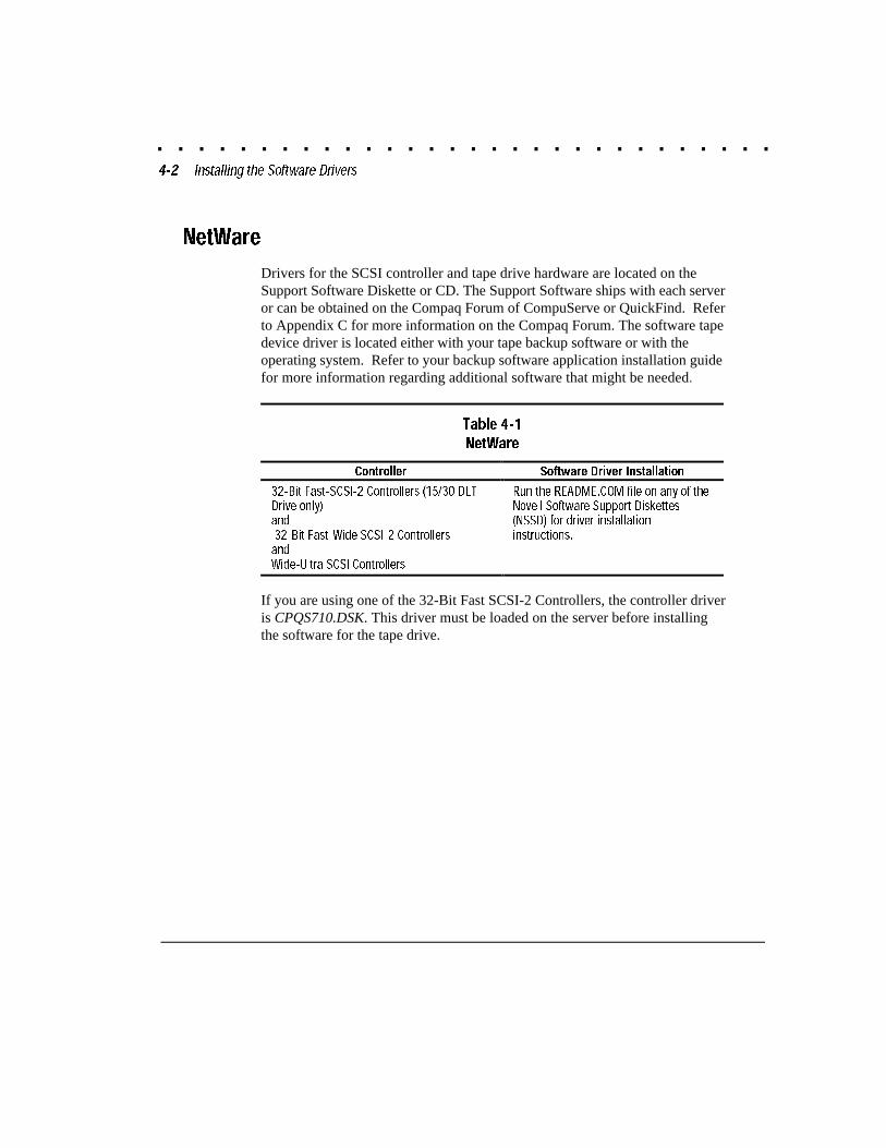
NetWare
Drivers for the SCSI controller and tape drive hardware are located on theSupport Software Diskette or CD. The Support Software ships with each serveror can be obtained on the Compaq Forum of CompuServe or QuickFind. Referto Appendix C for more information on the Compaq Forum. The software tapedevice driver is located either with your tape backup software or with theoperating system. Refer to your backup software application installation guidefor more information regarding additional software that might be needed.
Table 4-1
NetWare
Controller Software Driver Installation
32-Bit Fast-SCSI-2 Controllers (15/30 DLTDrive only)and32-Bit Fast-Wide SCSI-2 ControllersandWide-Ultra SCSI Controllers
Run the README.COM file on any of theNovell Software Support Diskettes(NSSD) for driver installationinstructions.
If you are using one of the 32-Bit Fast SCSI-2 Controllers, the controller driveris CPQS710.DSK. This driver must be loaded on the server before installingthe software for the tape drive.
. . . . . . . . . . . . . . . . . . . . . . . . . . . . . .4-3
Compaq DLT Drive User Guide
Writer: Jim Belew Project: Installing the Software Drivers Comments: 185292.002 finalFile Name:G-CH4.DOC Last Saved On:3/13/97 7:35 AM
ASPI Support
The README.COM on the Novell Software Support Diskette (NSSD)outlines the specific drivers you need to support ASPI tape backupapplications.
If you are using a tape backup application that uses the Advanced SCSIProgramming Interface (ASPI), such as ARCserve from Compaq, refer to theinformation provided with your application NLM to determine whether it usesASPI.
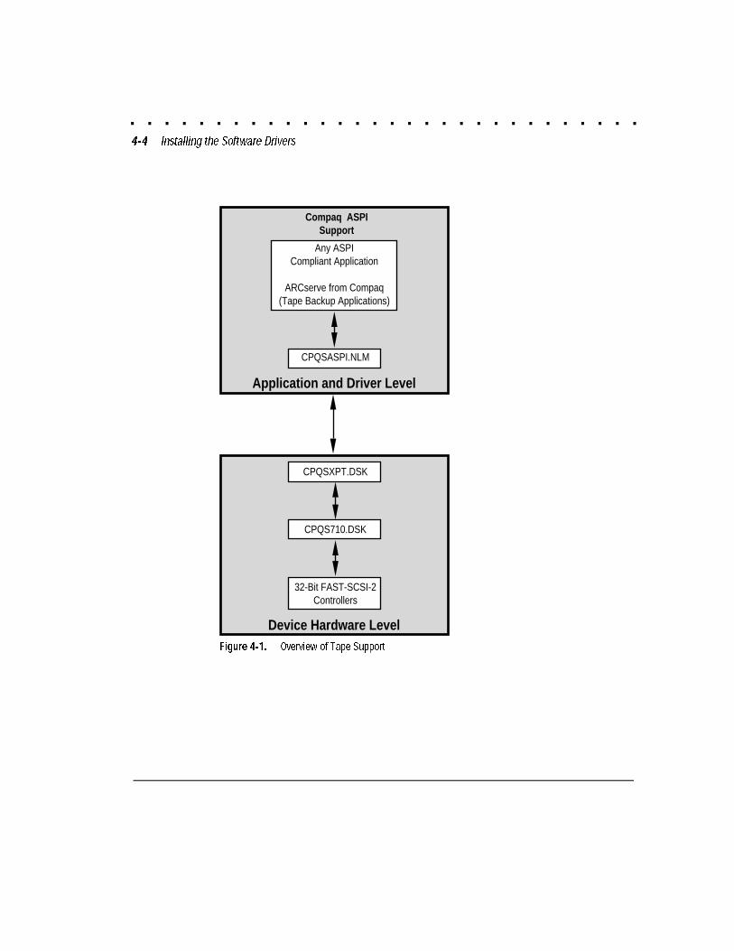
The Compaq ASPI driver, CPQSASPI.NLM, provides ASPI support for theCompaq SCSI architecture for applications that require this interface.Figure 4-1 shows the relationship of the ASPI-based tape application, CompaqASPI support, and components in the device hardware level.
All of the required drivers for ASPI tape support are provided on the NovellSoftware Support Diskette (NSSD). This diskette or CD ships with each serveror can be obtained on the Compaq Forum of CompuServe or QuickFind (SeeAppendix C).
The SCSI.RDM file on the NSSD diskette gives complete instructions on howto load these drivers and troubleshoot any problems.
. . . . . . . . . . . . . . . . . . . . . . . . . . . . . .4-4 Installing the Software Drivers
Writer: Jim Belew Project: Installing the Software Drivers Comments: 185292.002 finalFile Name:G-CH4.DOC Last Saved On:3/13/97 7:35 AM
Application and Driver Level
Device Hardware Level
32-Bit FAST-SCSI-2Controllers
Compaq ASPISupport
Any ASPICompliant Application
ARCserve from Compaq(Tape Backup Applications)
CPQSASPI.NLM
CPQS710.DSK
CPQSXPT.DSK
Figure 4-1. Overview of Tape Support
. . . . . . . . . . . . . . . . . . . . . . . . . . . . . .4-5
Compaq DLT Drive User Guide
Writer: Jim Belew Project: Installing the Software Drivers Comments: 185292.002 finalFile Name:G-CH4.DOC Last Saved On:3/13/97 7:35 AM
Microsoft Windows NT
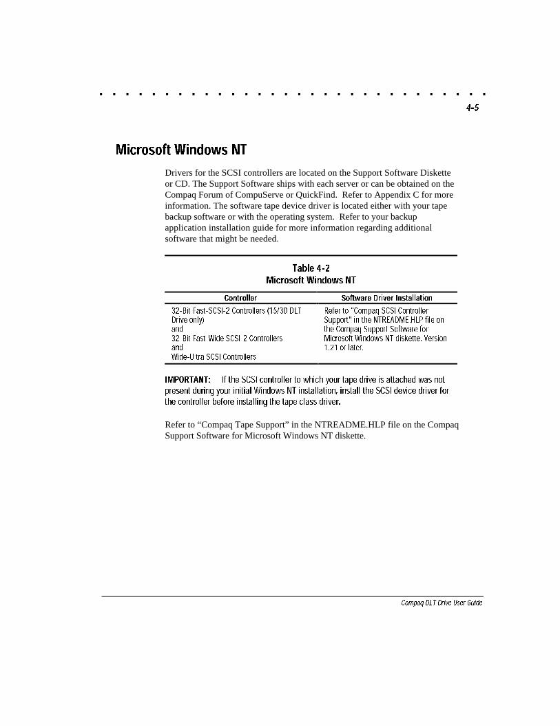
Drivers for the SCSI controllers are located on the Support Software Disketteor CD. The Support Software ships with each server or can be obtained on theCompaq Forum of CompuServe or QuickFind. Refer to Appendix C for moreinformation. The software tape device driver is located either with your tapebackup software or with the operating system. Refer to your backupapplication installation guide for more information regarding additionalsoftware that might be needed.
Table 4-2Microsoft Windows NT
Controller Software Driver Installation
32-Bit Fast-SCSI-2 Controllers (15/30 DLTDrive only)and32-Bit Fast-Wide SCSI-2 ControllersandWide-Ultra SCSI Controllers
Refer to "Compaq SCSI ControllerSupport" in the NTREADME.HLP file onthe Compaq Support Software forMicrosoft Windows NT diskette, Version1.21 or later.
IMPORTANT: If the SCSI controller to which your tape drive is attached was notpresent during your initial Windows NT installation, install the SCSI device driver forthe controller before installing the tape class driver.
Refer to “Compaq Tape Support” in the NTREADME.HLP file on the CompaqSupport Software for Microsoft Windows NT diskette.
. . . . . . . . . . . . . . . . . . . . . . . . . . . . . .4-6 Installing the Software Drivers
Writer: Jim Belew Project: Installing the Software Drivers Comments: 185292.002 finalFile Name:G-CH4.DOC Last Saved On:3/13/97 7:35 AM
Microsoft Windows 95
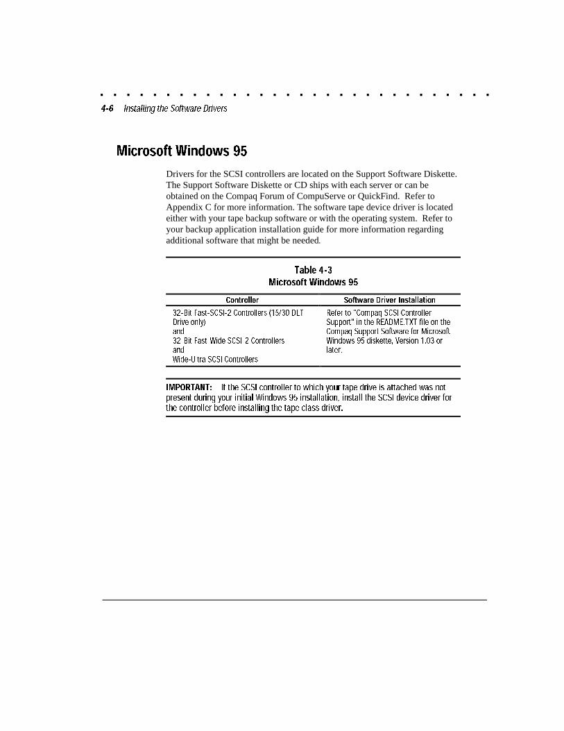
Drivers for the SCSI controllers are located on the Support Software Diskette.The Support Software Diskette or CD ships with each server or can beobtained on the Compaq Forum of CompuServe or QuickFind. Refer toAppendix C for more information. The software tape device driver is locatedeither with your tape backup software or with the operating system. Refer toyour backup application installation guide for more information regardingadditional software that might be needed.
Table 4-3Microsoft Windows 95
Controller Software Driver Installation
32-Bit Fast-SCSI-2 Controllers (15/30 DLTDrive only)and32-Bit Fast-Wide SCSI-2 ControllersandWide-Ultra SCSI Controllers
Refer to "Compaq SCSI ControllerSupport" in the README.TXT file on theCompaq Support Software for MicrosoftWindows 95 diskette, Version 1.03 orlater.
IMPORTANT: If the SCSI controller to which your tape drive is attached was notpresent during your initial Windows 95 installation, install the SCSI device driver forthe controller before installing the tape class driver.
. . . . . . . . . . . . . . . . . . . . . . . . . . . . . .4-7
Compaq DLT Drive User Guide
Writer: Jim Belew Project: Installing the Software Drivers Comments: 185292.002 finalFile Name:G-CH4.DOC Last Saved On:3/13/97 7:35 AM
SCO UNIX
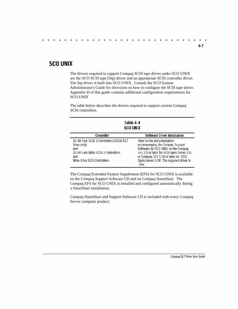
The drivers required to support Compaq SCSI tape drives under SCO UNIXare the SCO SCSI tape (Stp) driver and an appropriate SCSI controller driver.The Stp driver is built into SCO UNIX. Consult the SCO SystemAdministrator's Guide for directions on how to configure the SCSI tape driver.Appendix D of this guide contains additional configuration requirements forSCO UNIX
The table below describes the drivers required to support current CompaqSCSI controllers.
Table 4-4SCO UNIX
Controller Software Driver Installation
32-Bit Fast-SCSI-2 Controllers (15/30 DLTDrive only)and32-Bit Fast-Wide SCSI-2 ControllersandWide-Ultra SCSI Controllers
Refer to the documentationaccompanying the Compaq SupportSoftware for SCO UNIX, or the CompaqEFS 3.X or later for SCO Open Server 3.0,or Compaq EFS 5.1X or later for SCOOpen Server 5.0X. The required driver is"cha".
The Compaq Extended Feature Supplement (EFS) for SCO UNIX is availableon the Compaq Support Software CD and on Compaq SmartStart. TheCompaq EFS for SCO UNIX is installed and configured automatically duringa SmartStart installation.
Compaq SmartStart and Support Software CD is included with every CompaqServer computer product.
. . . . . . . . . . . . . . . . . . . . . . . . . . . . . .4-8 Installing the Software Drivers
Writer: Jim Belew Project: Installing the Software Drivers Comments: 185292.002 finalFile Name:G-CH4.DOC Last Saved On:3/13/97 7:35 AM
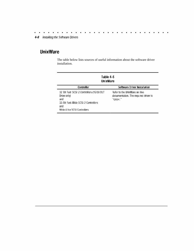
UnixWare
The table below lists sources of useful information about the software driverinstallation.
Table 4-5UnixWare
Controller Software Driver Installation
32-Bit Fast-SCSI-2 Controllers (15/30 DLTDrive only)and32-Bit Fast-Wide SCSI-2 ControllersandWide-Ultra SCSI Controllers
Refer to the UnixWare on-linedocumentation. The required driver is�cpqsc."
. . . . . . . . . . . . . . . . . . . . . . . . . . . . . .4-9
Compaq DLT Drive User Guide
Writer: Jim Belew Project: Installing the Software Drivers Comments: 185292.002 finalFile Name:G-CH4.DOC Last Saved On:3/13/97 7:35 AM
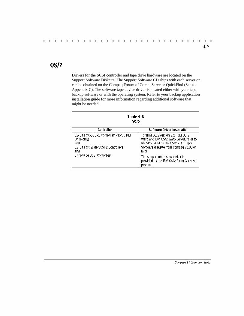
OS/2
Drivers for the SCSI controller and tape drive hardware are located on theSupport Software Diskette. The Support Software CD ships with each server orcan be obtained on the Compaq Forum of CompuServe or QuickFind (See toAppendix C). The software tape device driver is located either with your tapebackup software or with the operating system. Refer to your backup applicationinstallation guide for more information regarding additional software thatmight be needed.
Table 4-6OS/2
Controller Software Driver Installation
32-Bit Fast-SCSI-2 Controllers (15/30 DLTDrive only)and32-Bit Fast-Wide SCSI-2 ControllersandUltra-Wide SCSI Controllers
For IBM OS/2 version 2.X, IBM OS/2Warp and IBM OS/2 Warp Server, refer tofile SCSI.RDM on the OS/2 2.X SupportSoftware diskette from Compaq v2.00 orlater.
The support for this controller isprovided by the IBM OS/2 2.x or 3.x baseproduct.
. . . . . . . . . . . . . . . . . . . . . . . . . . . . . .4-10 Installing the Software Drivers
Writer: Jim Belew Project: Installing the Software Drivers Comments: 185292.002 finalFile Name:G-CH4.DOC Last Saved On:3/13/97 7:35 AM
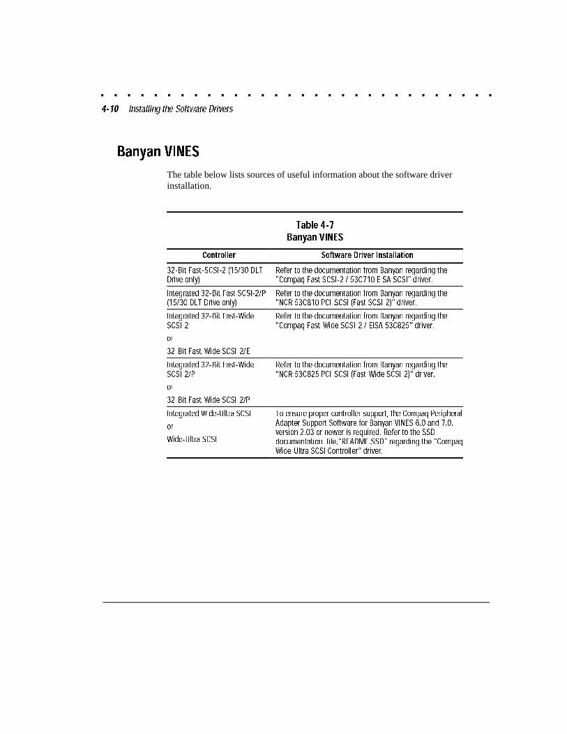
Banyan VINES
The table below lists sources of useful information about the software driverinstallation.
Table 4-7Banyan VINES
Controller Software Driver Installation
32-Bit Fast-SCSI-2 (15/30 DLTDrive only)
Refer to the documentation from Banyan regarding the�Compaq Fast SCSI-2 / 53C710 EISA SCSI� driver.
Integrated 32-Bit Fast SCSI-2/P(15/30 DLT Drive only)
Refer to the documentation from Banyan regarding the"NCR 53C810 PCI-SCSI (Fast SCSI-2)� driver.
Integrated 32-Bit Fast-WideSCSI-2
or
32-Bit Fast-Wide SCSI-2/E
Refer to the documentation from Banyan regarding the"Compaq Fast-Wide SCSI-2 / EISA 53C825� driver.
Integrated 32-Bit Fast-WideSCSI-2/P
or
32-Bit Fast-Wide SCSI-2/P
Refer to the documentation from Banyan regarding the"NCR 53C825 PCI-SCSI (Fast-Wide SCSI-2)� driver.
Integrated Wide-Ultra SCSI
or
Wide-Ultra SCSI
To ensure proper controller support, the Compaq PeripheralAdapter Support Software for Banyan VINES 6.0 and 7.0,version 2.03 or newer is required. Refer to the SSDdocumentation file,�README.SSD� regarding the �CompaqWide-Ultra SCSI Controller� driver.
. . . . . . . . . . . . . . . . . . . . . . . . . . . . . .5-1
Compaq DLT Drive User Guide
Writer: Jim Belew Project: Operating the DLT Drive Comments: 185292.002 finalFile Name:H-CH5.DOC Last Saved On:3/13/97 10:36 AM
Chapter 5
Operating the DLT Drive
This section describes the DLT Drive and its operation.
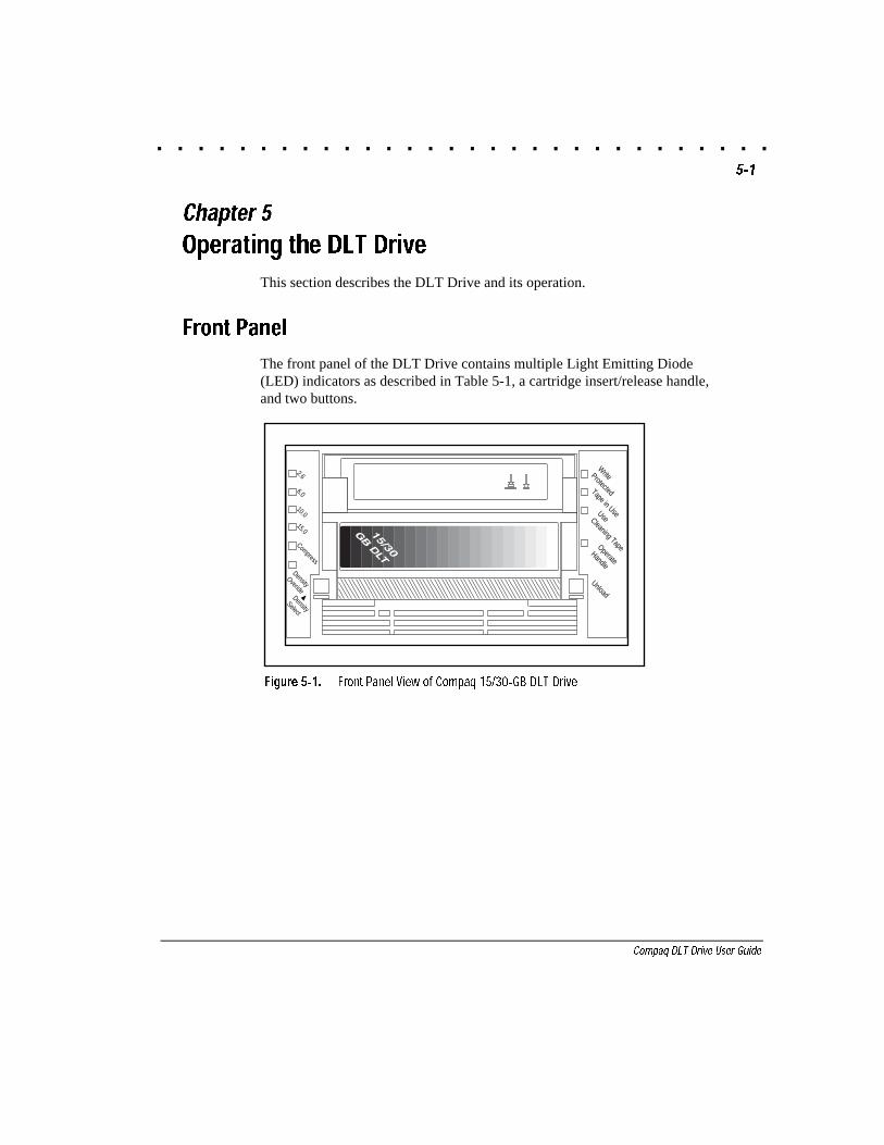
Front Panel
The front panel of the DLT Drive contains multiple Light Emitting Diode(LED) indicators as described in Table 5-1, a cartridge insert/release handle,and two buttons.
WriteProtectedTape in UseUseCleaning TapeOperateHandle
10.0
Compress
DensityOveride
DensitySelect
2.6
6.0
Unload
DLT_049.EPS
15.0
Figure 5-1. Front Panel View of Compaq 15/30-GB DLT Drive
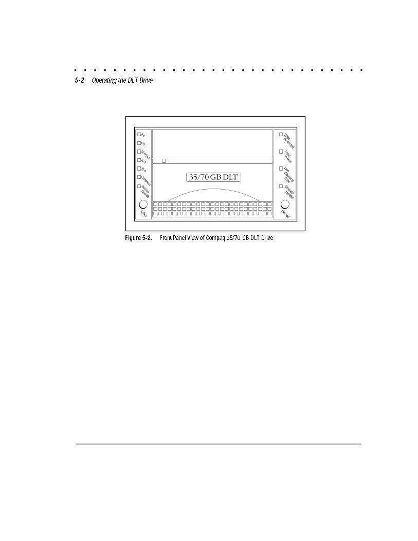
. . . . . . . . . . . . . . . . . . . . . . . . . . . . . .5-2 Operating the DLT Drive
Writer: Jim Belew Project: Operating the DLT Drive Comments: 185292.002 finalFile Name:H-CH5.DOC Last Saved On:3/13/97 10:36 AM
Write ProtectedTape in Use
Use Cleaning
TapeOperate
Handle
20.0
35.0
CompressDensity Overide
6.0
2.6
10.0/15.0
Unload
Select
DLT3-001.EPS
Figure 5-2. Front Panel View of Compaq 35/70-GB DLT Drive
. . . . . . . . . . . . . . . . . . . . . . . . . . . . . .5-3
Compaq DLT Drive User Guide
Writer: Jim Belew Project: Operating the DLT Drive Comments: 185292.002 finalFile Name:H-CH5.DOC Last Saved On:3/13/97 10:36 AM
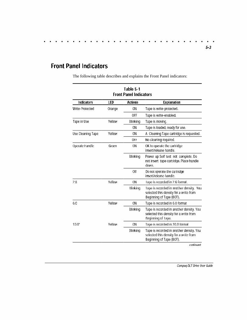
Front Panel Indicators
The following table describes and explains the Front Panel indicators:
Table 5-1Front Panel Indicators
Indicators LED Actions Explanation
Write-Protected Orange ON Tape is write-protected.
OFF Tape is write-enabled.
Tape in Use Yellow Blinking Tape is moving.
ON Tape is loaded; ready for use.
Use Cleaning Tape Yellow ON A Cleaning Tape cartridge is requested.
OFF No cleaning required.
Operate Handle Green ON OK to operate the cartridgeinsert/release handle.
Blinking Power-up Self-test not complete. Donot insert tape cartridge. Place handledown.
Off Do not operate the cartridgeinsert/release handle.
2.6 Yellow ON Tape is recorded in 2.6 format.
Blinking Tape is recorded in another density. Youselected this density for a write fromBeginning of Tape (BOT).
6.0 Yellow ON Tape is recorded in 6.0 format
Blinking Tape is recorded in another density. Youselected this density for a write fromBeginning of Tape.
10.0* Yellow ON Tape is recorded in.10.0 format.
Blinking Tape is recorded in another density. Youselected this density for a write fromBeginning of Tape (BOT).
continued
. . . . . . . . . . . . . . . . . . . . . . . . . . . . . .5-4 Operating the DLT Drive
Writer: Jim Belew Project: Operating the DLT Drive Comments: 185292.002 finalFile Name:H-CH5.DOC Last Saved On:3/13/97 10:36 AM
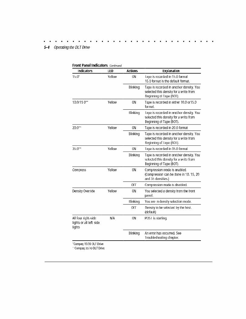
Front Panel Indicators Continued
Indicators LED Actions Explanation
15.0* Yellow ON Tape is recorded in 15.0 format.15.0 format is the default format.
Blinking Tape is recorded in another density. Youselected this density for a write fromBeginning of Tape (BOT).
10.0/15.0** Yellow ON Tape is recorded in either 10.0 or15.0format.
Blinking Tape is recorded in another density. Youselected this density for a write fromBeginning of Tape (BOT).
20.0** Yellow ON Tape is recorded in 20.0 format.
Blinking Tape is recorded in another density. Youselected this density for a write fromBeginning of Tape (BOT).
35.0** Yellow ON Tape is recorded in 35.0 format
Blinking Tape is recorded in another density. Youselected this density for a write fromBeginning of Tape (BOT).
Compress Yellow ON Compression mode is enabled.(Compression can be done in 10, 15, 20and 35 densities.)
OFF Compression mode is disabled.
Density Override Yellow ON You selected a density from the frontpanel.
Blinking You are in density selection mode.
OFF Density to be selected by the host.(default)
All four right-sidelights or all left-sidelights
N/A ON POST is starting.
Blinking An error has occurred. SeeTroubleshooting chapter.
*Compaq 15/30 DLT Drive
**Compaq 35/70 DLT Drive
. . . . . . . . . . . . . . . . . . . . . . . . . . . . . .5-5
Compaq DLT Drive User Guide
Writer: Jim Belew Project: Operating the DLT Drive Comments: 185292.002 finalFile Name:H-CH5.DOC Last Saved On:3/13/97 10:36 AM
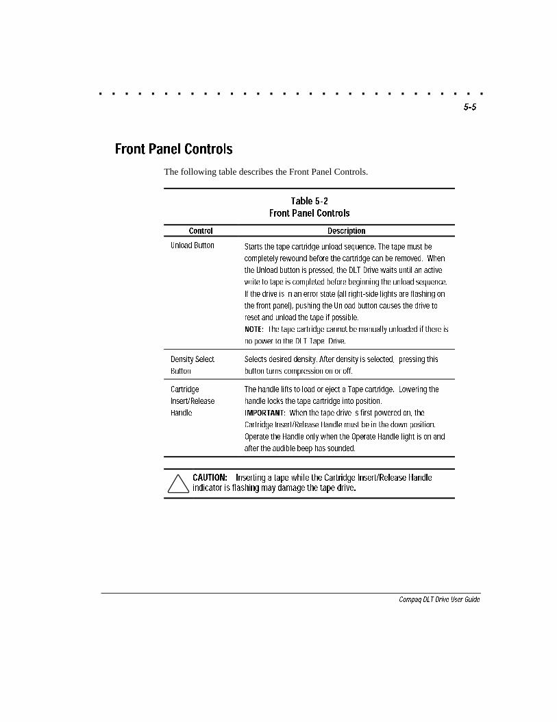
Front Panel Controls
The following table describes the Front Panel Controls.
Table 5-2Front Panel Controls
Control Description
Unload Button Starts the tape cartridge unload sequence. The tape must be
completely rewound before the cartridge can be removed. When
the Unload button is pressed, the DLT Drive waits until an active
write to tape is completed before beginning the unload sequence.
If the drive is in an error state (all right-side lights are flashing on
the front panel), pushing the Unload button causes the drive to
reset and unload the tape if possible.
NOTE: The tape cartridge cannot be manually unloaded if there is
no power to the DLT Tape Drive.
Density Select
Button
Selects desired density. After density is selected, pressing this
button turns compression on or off.
Cartridge
Insert/Release
Handle
The handle lifts to load or eject a Tape cartridge. Lowering the
handle locks the tape cartridge into position.
IMPORTANT: When the tape drive is first powered on, the
Cartridge Insert/Release Handle must be in the down position.
Operate the Handle only when the Operate Handle light is on and
after the audible beep has sounded.
CAUTION: Inserting a tape while the Cartridge Insert/Release Handleindicator is flashing may damage the tape drive.
. . . . . . . . . . . . . . . . . . . . . . . . . . . . . .5-6 Operating the DLT Drive
Writer: Jim Belew Project: Operating the DLT Drive Comments: 185292.002 finalFile Name:H-CH5.DOC Last Saved On:3/13/97 10:36 AM
Power-On Self-Test (POST)
When power is initially applied, the DLT Tape Drive performs a Power-OnSelf-Test (POST). This starts a sequence of events indicated by the front panelLED indicators.
1. Turn the DLT Drive on.
2. All left-side indicators turn on for approximately three seconds, thenturn off.
3. The green Operate Handle, the orange Write Protect, and the yellowUse Cleaning Tape lights turn off.
4. The yellow Tape in Use indicator blinks while the tape drive initializes.
5. After initializing, if a tape cartridge is not loaded, the yellow Tape inUse indicator turns off, the green Operate Handle indicator turns on,and an audible beep occurs.
NOTE: POST will not complete until the Operate Handle is in the downposition. If POST is waiting for the handle to be put down, the Operate Handleindicator will flash.
The drive is now ready for operation.
Loading and Unloading aTape Cartridge
IMPORTANT: When loading or unloading a tape cartridge, the greenOperate Handle indicator must be on.
To load a tape cartridge, follow these steps, referring to Figure 4-3:
1. When the green Operate Handle indicator is on, lift the cartridgeinsert/release handle up.
2. Insert the cartridge.
3. Push the cartridge completely into the drive.
. . . . . . . . . . . . . . . . . . . . . . . . . . . . . .5-7
Compaq DLT Drive User Guide
Writer: Jim Belew Project: Operating the DLT Drive Comments: 185292.002 finalFile Name:H-CH5.DOC Last Saved On:3/13/97 10:36 AM
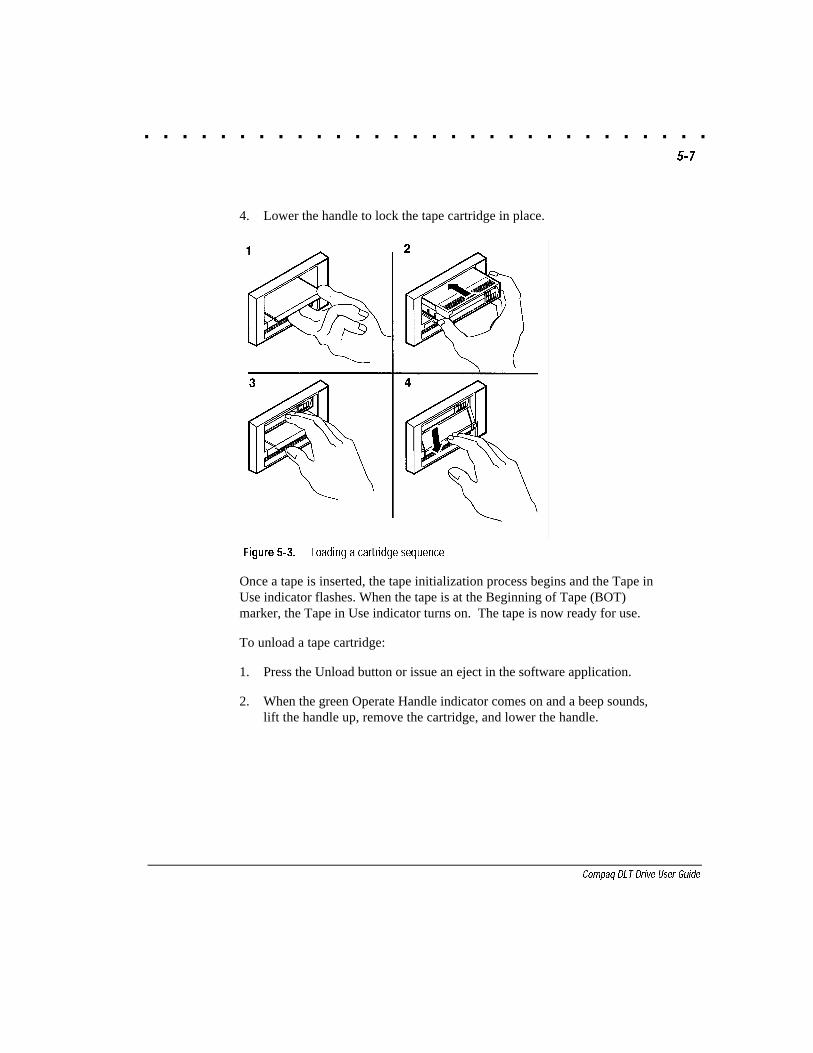
4. Lower the handle to lock the tape cartridge in place.
Figure 5-3. Loading a cartridge sequence
Once a tape is inserted, the tape initialization process begins and the Tape inUse indicator flashes. When the tape is at the Beginning of Tape (BOT)marker, the Tape in Use indicator turns on. The tape is now ready for use.
To unload a tape cartridge:
1. Press the Unload button or issue an eject in the software application.
2. When the green Operate Handle indicator comes on and a beep sounds,lift the handle up, remove the cartridge, and lower the handle.
. . . . . . . . . . . . . . . . . . . . . . . . . . . . . .5-8 Operating the DLT Drive
Writer: Jim Belew Project: Operating the DLT Drive Comments: 185292.002 finalFile Name:H-CH5.DOC Last Saved On:3/13/97 10:36 AM
Selecting Drive Density
You can select the density by using any of the following:
■ On a write from Beginning of Tape (BOT), change the tape density by:
❏ Pressing the Density Select button multiple times until the desiredDensity indicator flashes. Using the Density Select button alwaysoverrides a host selection.
❏ Making a programmable host selection via your operating system.(The Density Override indicator is off, indicating automatic or hostdensity selection.)
❏ Allowing the drive to default to density of cartridge being loadedusing compression (assuming the Density Select button or the hostselection was not used.) If previous written tape is inserted, drivedefaults to previous density.
■ On a prerecorded tape, the drive uses the recorded density for all readoperations and appended write operations.
CAUTION: If you reuse a prerecorded tape and write from the beginningof tape (BOT), all prerecorded data is lost. Density changes are also lostsince they only occur when writing from BOT.
Refer to Table 5-3 for the results of density selection.
. . . . . . . . . . . . . . . . . . . . . . . . . . . . . .5-9
Compaq DLT Drive User Guide
Writer: Jim Belew Project: Operating the DLT Drive Comments: 185292.002 finalFile Name:H-CH5.DOC Last Saved On:3/13/97 10:36 AM
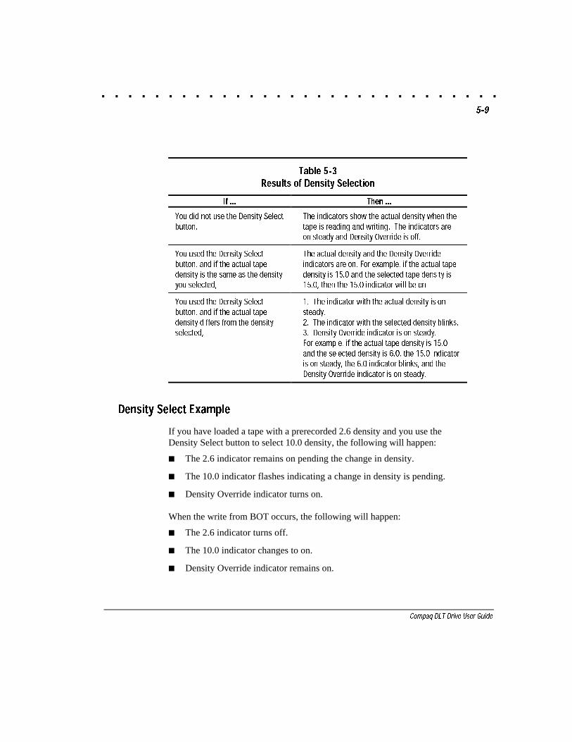
Table 5-3Results of Density Selection
If ... Then ...
You did not use the Density Selectbutton,
The indicators show the actual density when thetape is reading and writing. The indicators areon steady and Density Override is off.
You used the Density Selectbutton, and if the actual tapedensity is the same as the densityyou selected,
The actual density and the Density Overrideindicators are on. For example, if the actual tapedensity is 15.0 and the selected tape density is15.0, then the 15.0 indicator will be on.
You used the Density Selectbutton, and if the actual tapedensity differs from the densityselected,
1. The indicator with the actual density is onsteady.2. The indicator with the selected density blinks.3. Density Override indicator is on steady.For example, if the actual tape density is 15.0and the selected density is 6.0, the 15.0 indicatoris on steady, the 6.0 indicator blinks, and theDensity Override indicator is on steady.
Density Select Example
If you have loaded a tape with a prerecorded 2.6 density and you use theDensity Select button to select 10.0 density, the following will happen:
■ The 2.6 indicator remains on pending the change in density.
■ The 10.0 indicator flashes indicating a change in density is pending.
■ Density Override indicator turns on.
When the write from BOT occurs, the following will happen:
■ The 2.6 indicator turns off.
■ The 10.0 indicator changes to on.
■ Density Override indicator remains on.
. . . . . . . . . . . . . . . . . . . . . . . . . . . . . .5-10 Operating the DLT Drive
Writer: Jim Belew Project: Operating the DLT Drive Comments: 185292.002 finalFile Name:H-CH5.DOC Last Saved On:3/13/97 10:36 AM
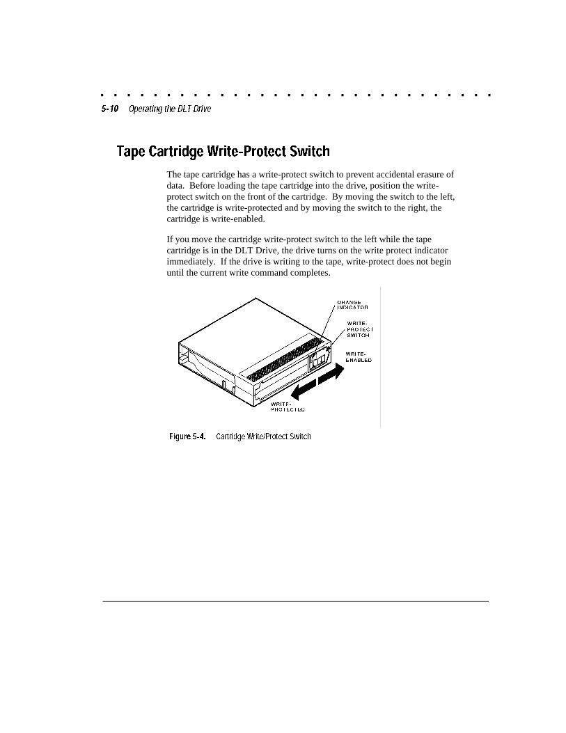
Tape Cartridge Write-Protect Switch
The tape cartridge has a write-protect switch to prevent accidental erasure ofdata. Before loading the tape cartridge into the drive, position the write-protect switch on the front of the cartridge. By moving the switch to the left,the cartridge is write-protected and by moving the switch to the right, thecartridge is write-enabled.
If you move the cartridge write-protect switch to the left while the tapecartridge is in the DLT Drive, the drive turns on the write protect indicatorimmediately. If the drive is writing to the tape, write-protect does not beginuntil the current write command completes.
Figure 5-4. Cartridge Write/Protect Switch
. . . . . . . . . . . . . . . . . . . . . . . . . . . . . .5-11
Compaq DLT Drive User Guide
Writer: Jim Belew Project: Operating the DLT Drive Comments: 185292.002 finalFile Name:H-CH5.DOC Last Saved On:3/13/97 10:36 AM
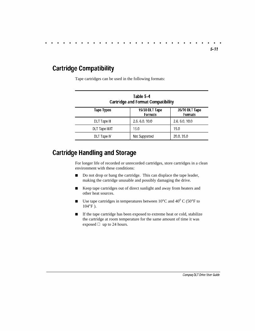
Cartridge Compatibility
Tape cartridges can be used in the following formats:
Table 5-4Cartridge and Format Compatibility
Tape Types 15/30 DLT TapeFormats
35/70 DLT TapeFormats
DLT Tape III 2.6, 6.0, 10.0 2.6, 6.0, 10.0
DLT Tape IIIXT 15.0 15.0
DLT Tape IV Not Supported 20.0, 35.0
Cartridge Handling and Storage
For longer life of recorded or unrecorded cartridges, store cartridges in a cleanenvironment with these conditions:
■ Do not drop or bang the cartridge. This can displace the tape leader,making the cartridge unusable and possibly damaging the drive.
■ Keep tape cartridges out of direct sunlight and away from heaters andother heat sources.
■ Use tape cartridges in temperatures between 10°C and 400 C (50°F to104°F ).
■ If the tape cartridge has been exposed to extreme heat or cold, stabilizethe cartridge at room temperature for the same amount of time it wasexposed up to 24 hours.
. . . . . . . . . . . . . . . . . . . . . . . . . . . . . .5-12 Operating the DLT Drive
Writer: Jim Belew Project: Operating the DLT Drive Comments: 185292.002 finalFile Name:H-CH5.DOC Last Saved On:3/13/97 10:36 AM
■ Do not place cartridges near electromagnetic interference sources, suchas terminals, motors, and video or X-ray equipment. Data on the tapecan be altered.
■ Store tape cartridges in a dust-free environment where the relativehumidity is between 20% and 80%. For longer cartridge life, store thecartridge at 20% to 40% relative humidity.
Place an identification label only in the slide-in slot on the front of thecartridge. Do not adhere labels to a cartridge anywhere except in the slide-inslot.
. . . . . . . . . . . . . . . . . . . . . . . . . . . . . .6-1
Compaq DLT Drive User Guide
Writer: Jim Belew Project: Tape Drive Cleaning Comments: 185292.002 finalFile Name:I-CH6.DOC Last Saved On:3/13/97 7:39 AM
Chapter 6
Tape Drive Cleaning
When the yellow “Use Cleaning Tape” indicator turns on, the drive head needscleaning. To clean the tape drive, insert the cleaning cartridge (Compaq kitPN 199704-001). When the cleaning is complete, a beep sounds and a greenindicator located by the Operate Handle comes on alerting you to remove thecleaning cartridge.
To clean the drive:
1. Wait for the green indicator to be on, lift the cartridge insert/releasehandle up.
2. Insert the cartridge.
3. Push the cartridge completely into the drive.
4. Lower the handle to lock the cleaning cartridge in place.
NOTE: The green light turns off and the yellow light continues to blink until itautomatically unloads the cleaning tape
If inserting a data cartridge again lights the cleaning indicator, it may mean adamaged data cartridge. However, the DLT Drive will still try to read the tapeand may even be able to do so successfully. If you think the tape is damaged,back up the data onto another cartridge, and discard the old cartridge.
NOTE: A damaged cartridge may cause unnecessary use of thecleaning cartridge.
IMPORTANT: To clean the heads of the DLT Drive, use only cleaningcartridges compatible with the DLT Drives.
. . . . . . . . . . . . . . . . . . . . . . . . . . . . . .6-2 Tape Drive Cleaning
Writer: Jim Belew Project: Tape Drive Cleaning Comments: 185292.002 finalFile Name:I-CH6.DOC Last Saved On:3/13/97 7:39 AM
If the “Use Cleaning Tape” indicator stays lit after the cleaning cartridge hasbeen used and unloaded, the cleaning has not been done and the cartridge hasexpired. Replace the cleaning cartridge and discard the old one.
NOTE: The cleaning cartridge expires after 20 uses.
If the “Use Cleaning Tape” indicator still lights after you have cleaned thedrive head, your data cartridge may be causing the problem. Back up yourdata onto another data cartridge.
. . . . . . . . . . . . . . . . . . . . . . . . . . . . . .7-1
Compaq DLT Tape Drive User Guide
Writer: Jim Belew Project: Troubleshooting Comments: 185292.002 finalFile Name:J-CH7.DOC Last Saved On:3/13/97 7:39 AM
Chapter 7
Troubleshooting
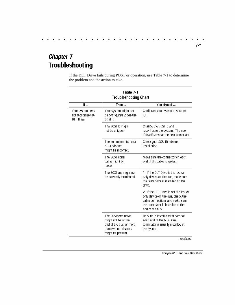
If the DLT Drive fails during POST or operation, use Table 7-1 to determinethe problem and the action to take.
Table 7-1Troubleshooting Chart
If ... Then ... You should ...
Your system doesnot recognize theDLT Drive,
Your system might notbe configured to see theSCSI ID.
Configure your system to see theID.
The SCSI ID mightnot be unique.
Change the SCSI ID andreconfigure the system. The newID is effective at the next power-on.
The parameters for yourSCSI adaptermight be incorrect.
Check your SCSI ID adapterinstallation.
The SCSI signalcable might beloose.
Make sure the connector on eachend of the cable is seated.
The SCSI bus might notbe correctly terminated.
1. If the DLT Drive is the last oronly device on the bus, make surethe terminator is installed on thedrive.
2. If the DLT Drive is not the last oronly device on the bus, check thecable connections and make surethe terminator is installed at theend of the bus.
The SCSI terminatormight not be at theend of the bus, or morethan two terminatorsmight be present.
Be sure to install a terminator ateach end of the bus. Oneterminator is usually installed atthe system.
continued
. . . . . . . . . . . . . . . . . . . . . . . . . . . . . .7-2 Troubleshooting
Writer: Jim Belew Project: Troubleshooting Comments: 185292.002 finalFile Name:J-CH7.DOC Last Saved On:3/13/97 7:39 AM
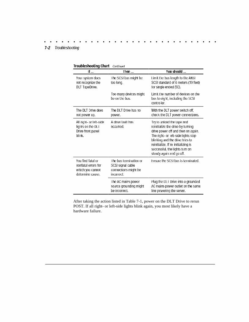
Troubleshooting Chart Continued
If ... Then ... You should ...
Your system doesnot recognize theDLT TapeDrive,
The SCSI bus might betoo long.
Limit the bus length to the ANSISCSI standard of 6 meters (19 feet)for single ended (SE).
Too many devices mightbe on the bus.
Limit the number of devices on thebus to eight, including the SCSIcontroller.
The DLT Drive doesnot power up,
The DLT Drive has nopower.
With the DLT power switch off,check the DLT power connections.
All right- or left-sidelights on the DLTDrive front panelblink,
A drive fault hasoccurred.
Try to unload the tape andreinitialize the drive by turningdrive power off and then on again.The right- or left-side lights stopblinking and the drive tries toreinitialize. If re-initializing issuccessful, the lights turn onsteady again and go off.
You find fatal ornonfatal errors forwhich you cannotdetermine cause,
The bus termination orSCSI signal cableconnections might beincorrect.
Ensure the SCSI bus is terminated.
The AC mains powersource grounding mightbe incorrect.
Plug the DLT Drive into a groundedAC mains power outlet on the sameline powering the server.
After taking the action listed in Table 7-1, power on the DLT Drive to rerunPOST. If all right- or left-side lights blink again, you most likely have ahardware failure.
. . . . . . . . . . . . . . . . . . . . . . . . . . . . . .7-3
Compaq DLT Tape Drive User Guide
Writer: Jim Belew Project: Troubleshooting Comments: 185292.002 finalFile Name:J-CH7.DOC Last Saved On:3/13/97 7:39 AM
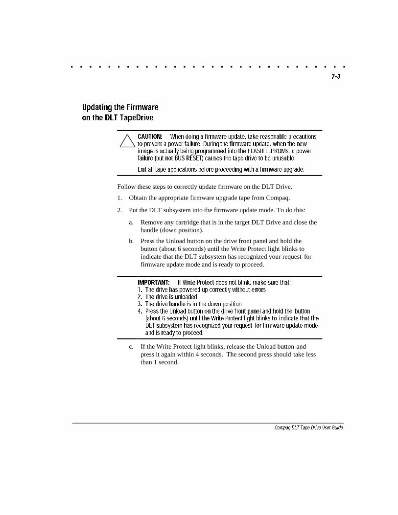
Updating the Firmwareon the DLT TapeDrive
CAUTION: When doing a firmware update, take reasonable precautionsto prevent a power failure. During the firmware update, when the newimage is actually being programmed into the FLASH EEPROMs, a powerfailure (but not BUS RESET) causes the tape drive to be unusable.
Exit all tape applications before proceeding with a firmware upgrade.
Follow these steps to correctly update firmware on the DLT Drive.
1. Obtain the appropriate firmware upgrade tape from Compaq.
2. Put the DLT subsystem into the firmware update mode. To do this:
a. Remove any cartridge that is in the target DLT Drive and close thehandle (down position).
b. Press the Unload button on the drive front panel and hold thebutton (about 6 seconds) until the Write Protect light blinks toindicate that the DLT subsystem has recognized your request forfirmware update mode and is ready to proceed.
IMPORTANT: If Write Protect does not blink, make sure that:1. The drive has powered up correctly without errors2. The drive is unloaded3. The drive handle is in the down position4. Press the Unload button on the drive front panel and hold the button
(about 6 seconds) until the Write Protect light blinks to indicate that theDLT subsystem has recognized your request for firmware update modeand is ready to proceed.
c. If the Write Protect light blinks, release the Unload button andpress it again within 4 seconds. The second press should take lessthan 1 second.
. . . . . . . . . . . . . . . . . . . . . . . . . . . . . .7-4 Troubleshooting
Writer: Jim Belew Project: Troubleshooting Comments: 185292.002 finalFile Name:J-CH7.DOC Last Saved On:3/13/97 7:39 AM
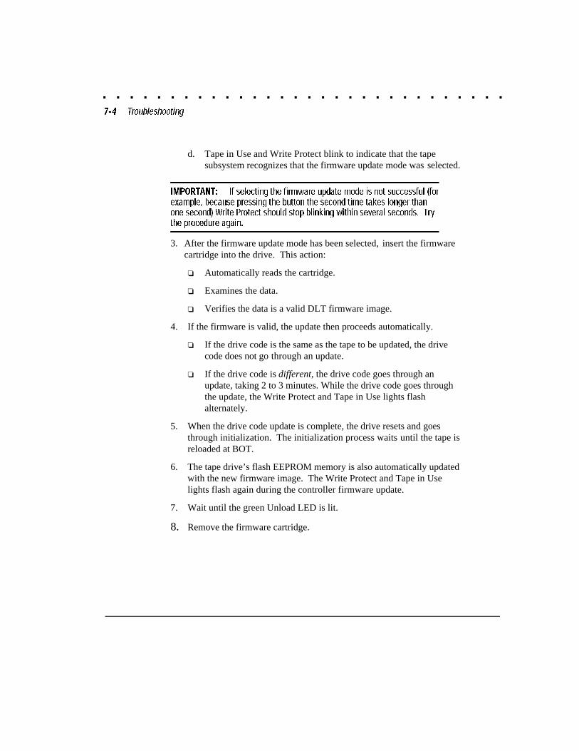
d. Tape in Use and Write Protect blink to indicate that the tapesubsystem recognizes that the firmware update mode was selected.
IMPORTANT: If selecting the firmware update mode is not successful (forexample, because pressing the button the second time takes longer thanone second) Write Protect should stop blinking within several seconds. Trythe procedure again.
3. After the firmware update mode has been selected, insert the firmwarecartridge into the drive. This action:
❏ Automatically reads the cartridge.
❏ Examines the data.
❏ Verifies the data is a valid DLT firmware image.
4. If the firmware is valid, the update then proceeds automatically.
❏ If the drive code is the same as the tape to be updated, the drivecode does not go through an update.
❏ If the drive code is different, the drive code goes through anupdate, taking 2 to 3 minutes. While the drive code goes throughthe update, the Write Protect and Tape in Use lights flashalternately.
5. When the drive code update is complete, the drive resets and goesthrough initialization. The initialization process waits until the tape isreloaded at BOT.
6. The tape drive’s flash EEPROM memory is also automatically updatedwith the new firmware image. The Write Protect and Tape in Uselights flash again during the controller firmware update.
7. Wait until the green Unload LED is lit.
8. Remove the firmware cartridge.
. . . . . . . . . . . . . . . . . . . . . . . . . . . . . .7-5
Compaq DLT Tape Drive User Guide
Writer: Jim Belew Project: Troubleshooting Comments: 185292.002 finalFile Name:J-CH7.DOC Last Saved On:3/13/97 7:39 AM
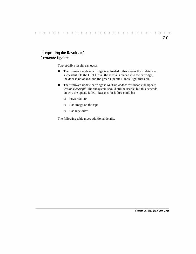
Interpreting the Results ofFirmware Update
Two possible results can occur:
■ The firmware update cartridge is unloaded − this means the update wassuccessful. On the DLT Drive, the media is placed into the cartridge,the door is unlocked, and the green Operate Handle light turns on.
■ The firmware update cartridge is NOT unloaded: this means the updatewas unsuccessful. The subsystem should still be usable, but this dependson why the update failed. Reasons for failure could be:
❏ Power failure
❏ Bad image on the tape
❏ Bad tape drive
The following table gives additional details.
. . . . . . . . . . . . . . . . . . . . . . . . . . . . . .7-6 Troubleshooting
Writer: Jim Belew Project: Troubleshooting Comments: 185292.002 finalFile Name:J-CH7.DOC Last Saved On:3/13/97 7:39 AM
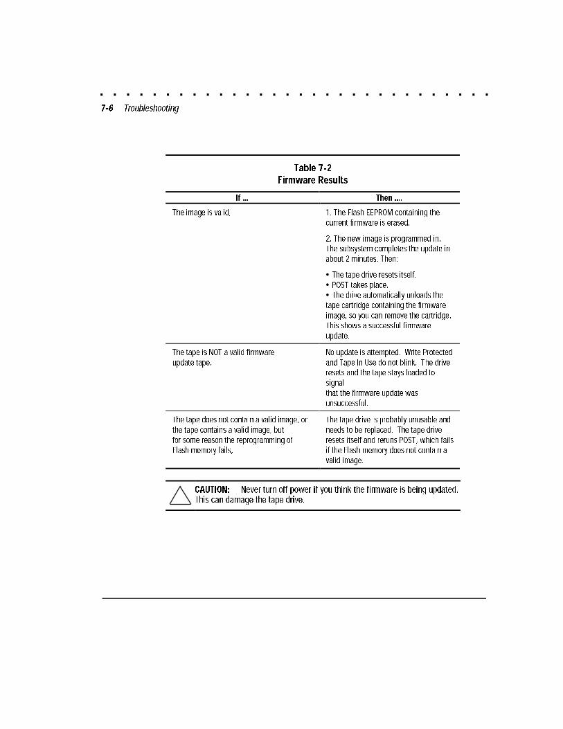
Table 7-2
Firmware Results
If ... Then ....
The image is valid, 1. The Flash EEPROM containing thecurrent firmware is erased.
2. The new image is programmed in.The subsystem completes the update inabout 2 minutes. Then:
• The tape drive resets itself.• POST takes place.• The drive automatically unloads thetape cartridge containing the firmwareimage, so you can remove the cartridge.This shows a successful firmwareupdate.
The tape is NOT a valid firmwareupdate tape,
No update is attempted. Write Protectedand Tape In Use do not blink. The driveresets and the tape stays loaded tosignalthat the firmware update wasunsuccessful.
The tape does not contain a valid image, orthe tape contains a valid image, butfor some reason the reprogramming ofFlash memory fails,
The tape drive is probably unusable andneeds to be replaced. The tape driveresets itself and reruns POST, which failsif the Flash memory does not contain avalid image.
CAUTION: Never turn off power if you think the firmware is being updated.This can damage the tape drive.
. . . . . . . . . . . . . . . . . . . . . . . . . . . . . .A-1
Compaq DLT Tape Drive User Guide
Writer: Jim Belew Project: Power Cord Set Requirements Comments: 185292.002 Walk-thruFile Name:K-APPA.DOC Last Saved On:3/13/97 7:39 AM
Appendix APower Cord Set Requirements
The wide-range input feature of your Compaq DLT Tape Drive permits it tooperate from any line voltage between 100 to 240 volts AC.
The power cord set (appliance coupler, flexible cord, and wall plug) youreceived with your Compaq DLT Tape Drive meets the requirements for usein the country where you purchased your equipment.
Power cord sets for use in other countries must meet the requirements of thecountry where you use the Compaq DLT Tape Drive. For more informationon power cord set requirements, contact your Authorized Compaq Dealer.
General Requirements
The requirements listed below are applicable to all countries:
1. The length of the power cord set must be at least 5.00 feet (1.5 m) anda maximum of 14.7 feet (4.5 m).
2. All power cord sets must be approved by an acceptable accreditedagency responsible for evaluation in the country where the power cordset will be used.
3. The power cord set must have a minimum current capacity of 10A anda nominal voltage rating of 125 or 250 volts AC, as required by eachcountry’s power system.
4. The appliance coupler must meet the mechanical configuration of anEN 60 320/IEC 320 Standard Sheet C13 connector, for mating with theappliance inlet.
. . . . . . . . . . . . . . . . . . . . . . . . . . . . . .A-2 Power Cord Set Requirements
Writer: Jim Belew Project: Power Cord Set Requirements Comments: 185292.002 Walk-thruFile Name:K-APPA.DOC Last Saved On:3/13/97 7:39 AM
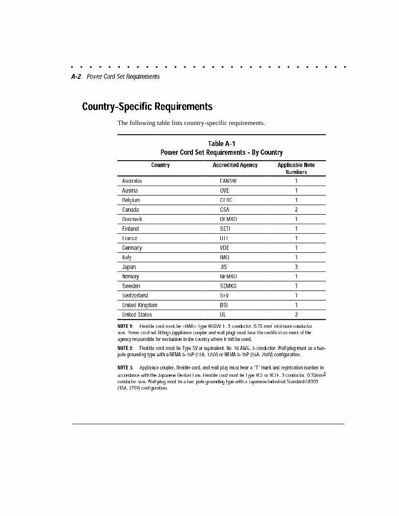
Country-Specific Requirements
The following table lists country-specific requirements.
Table A-1
Power Cord Set Requirements - By Country
Country Accredited Agency Applicable NoteNumbers
Australia EANSW 1
Austria OVE 1
Belgium CEBC 1
Canada CSA 2
Denmark DEMKO 1
Finland SETI 1
France UTE 1
Germany VDE 1
Italy IMQ 1
Japan JIS 3
Norway NEMKO 1
Sweden SEMKO 1
Switzerland SEV 1
United Kingdom BSI 1
United States UL 2
NOTE 1: Flexible cord must be <HAR> Type HO5VV-F, 3-conductor, 0.75 mm2
minimum conductor
size. Power cord set fittings (appliance coupler and wall plug) must bear the certification mark of theagency responsible for evaluation in the country where it will be used.
NOTE 2: Flexible cord must be Type SV or equivalent, No. 18 AWG, 3-conductor. Wall plug must be a two-
pole grounding type with a NEMA 5-15P (15A, 125V) or NEMA 6-15P (15A, 250V) configuration.
NOTE 3: Appliance coupler, flexible cord, and wall plug must bear a "T" mark and registration number in
accordance with the Japanese Dentori Law. Flexible cord must be Type VCT or VCTF, 3 conductor, 0.75mm2
conductor size. Wall plug must be a two-pole grounding type with a Japanese Industrial Standard C8303
(15A, 125V) configuration.
. . . . . . . . . . . . . . . . . . . . . . . . . . . . . .B-1
Compaq DLT Drive User Guide
Writer: Jim Belew Project: Electrostatic Discharge Comments: 185292.002 finalFile Name:L-APPB.DOC Last Saved On:3/13/97 7:53 AM
Appendix BElectrostatic Discharge
A discharge of static electricity from a finger or other conductor can damageprinted circuit boards or other static-sensitive devices. This type of damagemay reduce the life expectancy of the device.
Preventing Electrostatic Damage
To prevent electrostatic damage, observe the following precautions:
■ Avoid hand contact by transporting and storing parts instatic-safe containers.
■ Keep electrostatic-sensitive parts in their containers until they arrive atstatic-free workstations.
■ Place parts on a grounded surface before removing them fromtheir containers.
■ Avoid touching pins, leads, or circuitry.
■ Always be properly grounded when touching a static-sensitivecomponent or assembly.
Grounding Methods
You must be properly grounded when handling or installing electrostatic-sensitive parts. Use one or more of the following methods:
■ Use a wrist strap connected by a ground cord to a groundedworkstation or server chassis. Wrist straps are flexible straps with aminimum of one meg. ohm +/-10 percent resistance in the groundcords. To provide a proper ground, wear the strap snugly against yourskin.
■ If you are standing on conductive floors or dissipating floor mats, wearheelstraps, toestraps, or bootstraps on both feet.
■ Use conductive field service tools.
Use a portable field service kit with a folding static-dissipating workmat.

. . . . . . . . . . . . . . . . . . . . . . . . . . . . . .C-1
Compaq DLT Drive User Guide
Writer: Jim Belew Project: Getting Help Comments: 185292.002 finalFile Name:M-APPC.DOC Last Saved On:3/11/97 11:57 AM
Appendix CGetting Help
If you have a problem and have exhausted the information in this guide, youcan get further information and other help in the following locations.
Compaq Web Site
The Compaq Web Site has information on these products as well as the latestdrivers and Flash ROM images. You can access the Compaq Web Site bylogging on to the Internet at http://www.compaq.com.
Telephone Numbers
Contact your nearest Compaq Authorized Reseller or Service Provider formore information.
■ For the name of your nearest Compaq Authorized Reseller:
❏ In the United States, call 1-800-345-1518
❏ In Canada, call 1-800-263-5868
■ For Compaq technical support:❏ In the United States and Canada, call 1-800-386-2172
❏ Elsewhere, call one of the numbers listed below
Compaq Worldwide Technical Support Telephone Numbers
Location Voice FAX
APD 65-7503030 65-7504909
Argentina 54-1 313 3100 54-1 313 3100 Ext 21
Australia 61-2-9911-1955 61-2-9911-1900
Austria 0222-87816-16 0222-87816-82
Bahrain 973-210-214
Belgium (02) 716-96-96 (02) 725-22-13
Brazil 55 11 5505-3600 55 11 5505-3922 Ext 4336
Canada 1-800-386-2172
Caribbean 1-800-345-1518
Central America 281-378-2206
Continued
. . . . . . . . . . . . . . . . . . . . . . . . . . . . . .C-2 Getting Help
Writer: Jim Belew Project: Getting Help Comments: 185292.002 finalFile Name:M-APPC.DOC Last Saved On:3/11/97 11:57 AM
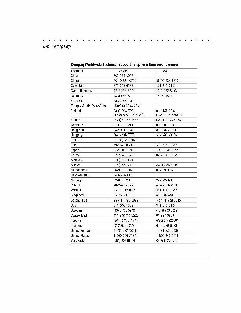
Compaq Worldwide Technical Support Telephone Numbers Continued
Location Voice FAX
Chile 562-274-3007
China 86-10-834-6721 86-10-834-6713
Colombia 571-345-0266 571-312-0157
Czech Republic 42-2-232-8772 42-2-232-8773
Denmark 45-90-4545 45-90-4595
Equador 593-2504540
Europe/Middle East/Africa (49) 089-9933-2891
Finland 9800-206-720(+358-800-1-206720)
90-6155-9899(+358-0-61559899
France (33 1) 41-33-4455 (33 1) 41-33-4263
Germany 0180-5-212111 089-9933-3399
Hong Kong 852-90116633 852-28671734
Hungary 36-1-201-8776 36-1-201-9696
India (91-80) 559-6023
Italy 392-57-90300 392-575-00686
Japan 0120-101589 +81 3-5402-5959
Korea 82-2-523-3575 82-2-3471-0321
Malaysia (603) 718-1636
Mexico (525) 229-7910 (525) 229-7988
Netherlands 06-91681616 06-8991116
New Zealand 649-307-3969
Norway 22-072-020 22-072-021
Poland 48-2-630-3535 48-2-630-3553
Portugal 351-1-4120132 351-1-4120654
Singapore 65-7503030 65-7504909
South Africa +27-11-728-6999 +27-11-728-3335
Spain 341-640-1302 341-640-0124
Sweden (46) 8 703 5240 (46) 8 703 5222
Switzerland 411 838 410/2222 01-837-0969
Taiwan (886) 2-3761170 (886) 2-7322660
Thailand 62-2-679-6222 62-2-679-6220
United Kingdom 44-81-332-3888 44-81-332-3409
United States 1-800-386-2172 1-800-345-1518
Venezuela (582) 953.69.44 (582) 952.86.70
. . . . . . . . . . . . . . . . . . . . . . . . . . . . . .D-1
Compaq DLT Drive User Guide
Writer: Jim Belew Project: Supplemental Information About SCO UNIX Comments: 185292.002 finalFile Name:N-APPD.DOC Last Saved On:3/11/97 11:57 AM
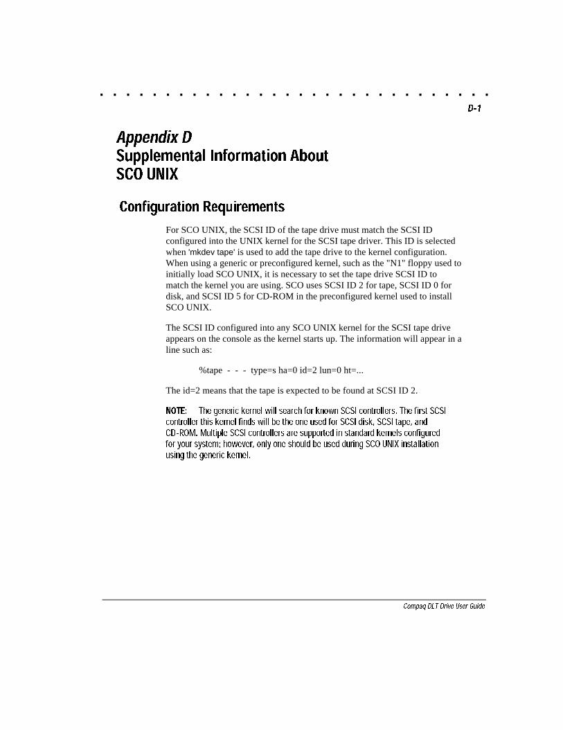
Appendix DSupplemental Information AboutSCO UNIX
Configuration Requirements
For SCO UNIX, the SCSI ID of the tape drive must match the SCSI IDconfigured into the UNIX kernel for the SCSI tape driver. This ID is selectedwhen 'mkdev tape' is used to add the tape drive to the kernel configuration.When using a generic or preconfigured kernel, such as the "N1" floppy used toinitially load SCO UNIX, it is necessary to set the tape drive SCSI ID tomatch the kernel you are using. SCO uses SCSI ID 2 for tape, SCSI ID 0 fordisk, and SCSI ID 5 for CD-ROM in the preconfigured kernel used to installSCO UNIX.
The SCSI ID configured into any SCO UNIX kernel for the SCSI tape driveappears on the console as the kernel starts up. The information will appear in aline such as:
%tape - - - type=s ha=0 id=2 lun=0 ht=...
The id=2 means that the tape is expected to be found at SCSI ID 2.
NOTE: The generic kernel will search for known SCSI controllers. The first SCSIcontroller this kernel finds will be the one used for SCSI disk, SCSI tape, andCD-ROM. Multiple SCSI controllers are supported in standard kernels configuredfor your system; however, only one should be used during SCO UNIX installationusing the generic kernel.
. . . . . . . . . . . . . . . . . . . . . . . . . . . . . .E-1
Compaq DLT Drive User Guide
Writer: Jim Belew Project: Regulatory Compliance Notices Comments: 185292.002 finalFile Name:O-APPE.DOC Last Saved On:3/11/97 11:58 AM
Appendix ERegulatory Compliance Notices
Federal Communications
Commission Notice
This equipment has been tested and found to comply with the limits for aClass B digital device, pursuant to Part 15 of the FCC Rules. These limits aredesigned to provide reasonable protection against harmful interference in aresidential installation. This equipment generates, uses, and can radiate radiofrequency energy and, if not installed and used in accordance with theinstructions, may cause harmful interference to radio communications.However, there is no guarantee that interference will not occur in a particularinstallation. If this equipment does cause harmful interference to radio ortelevision reception, which can be determined by turning the equipment offand on, the user is encouraged to try to correct the interference by one or moreof the following measures:
■ Reorient or relocate the receiving antenna.
■ Increase the separation between the equipment and receiver.
■ Connect the equipment into an outlet on a circuit different from that towhich the receiver is connected.
■ Consult the dealer or an experienced radio or television technician forhelp.
Modifications
The FCC requires the user to be notified that any changes or modificationsmade to this device that are not expressly approved by Compaq ComputerCorporation may void the user's authority to operate the equipment.
. . . . . . . . . . . . . . . . . . . . . . . . . . . . . .E-2 Regulatory Compliance Notices
Writer: Jim Belew Project: Regulatory Compliance Notices Comments: 185292.002 finalFile Name:O-APPE.DOC Last Saved On:3/11/97 11:58 AM
Cables
Connections to this device must be made with shielded cables with metallicRFI/EMI connector hoods in order to maintain compliance with FCC Rulesand Regulations.
Canadian Notice (Avis Canadien)
This Class B digital apparatus meets all requirements of the CanadianInterference-Causing Equipment Regulations.
Cet appareil numérique de la classe B respecte toutes les exigences duRèglement sur le matériel brouilleur du Canada.
European Union Notice
Products with the CE Marking comply with both the EMC Directive(89/336/EEC) and the Low Voltage Directive (73/23/EEC) issued by theCommission of the European Community.
Compliance with these directives implies conformity to the followingEuropean Norms (in brackets are the equivalent international standards):
■ EN55022 (CISPR 22) - Electromagnetic Interference
■ EN50082-1 (IEC801-2, IEC801-3, IEC801-4) - ElectromagneticImmunity
■ EN60950 (IEC950) - Product Safety
. . . . . . . . . . . . . . . . . . . . . . . . . . . . . .E-3
Compaq DLT Drive User Guide
Writer: Jim Belew Project: Regulatory Compliance Notices Comments: 185292.002 finalFile Name:O-APPE.DOC Last Saved On:3/11/97 11:58 AM
Japanese Notice
. . . . . . . . . . . . . . . . . . . . . . . . . . . . . .I-1
Compaq DLT Tape Drive User Guide
Writer: Jim Belew Project: Index Comments: 185292.002 Walk-thru
File Name:P-INDEX.DOC Last Saved On:3/11/97 11:57 AM
Index
A
Advanced SCSI ProgrammingInterface (ASPI) 4-3
Appliance couplerrequirements A-1
ARCserve from Compaq 4-3ASPI driver 4-3Automatic voltage sensing
feature A-1
B
Banyandrivers for hardware 4-10drivers for SCSI controller 4-10drivers for software 4-10
Beginning of Tape (BOT) 5-7
C
Cable terminator 2-5Cartridge
loading and unloading 5-6Cartridges
compatible modes 5-11handling and storage 5-11number of uses 6-2
Cleaning Cartridgehow to use 6-1troubleshooting 6-2
Cleaning Tapeuseful life 6-2when to use 6-1
Cleaning the drive 6-1Compaq EFS for SCO UNIX 4-7
Compaq SmartStart and SupportSoftware CD 2-1
Compatibility of cartridge and tapetypes 1-1
Compatibility of tape formats andtape types 5-11
Completing the Installation 2-6Compressed mode 1-1Compression algorithm 1-1Controller drivers
Banyan 4-10Netware 4-2OS/2 4-9SCO UNIX 4-7UnixWare 4-8Windows 95 4-6Windows NT 4-5
Controller requirements 1-2Country-specific power cord
requirements A-2
D
Daisy chaining 3-5Data compression
default 5-8selecting 5-8
Data compression ratio 1-1Data transfer rate 1-1Density
override indicator 5-8select button 5-8selecting 5-8
Digital Lempel-Ziv (DLZ)algorithm 1-1
DLT Drive SCSI ID default 2-2
. . . . . . . . . . . . . . . . . . . . . . . . . . . . . .I-2 Index
Writer: Jim Belew Project: Index Comments: 185292.002 Walk-thru
File Name:P-INDEX.DOC Last Saved On:3/11/97 11:57 AM
E
EFS for SCO UNIX 4-7Electrostatic Discharge B-1EPROM 7-3External DLT Drive
connecting 3-1SCSI ID default 3-1SCSI ID setting 3-2
F
Features of DLT drive 1-1Firmware
Interpreting results ofupgrade 7-5
Part Number 7-3troubleshooting 7-5updating 7-3
Form factor 1-1Formats 5-11Formatted capacity 1-2Front Panel Controls
described 5-5Front panel indicators 5-1
G
Getting HelpCompaq Website C-1Telephone numbers C-1
H
How to load/unload a tape cartridgeillustrated 5-6steps 5-6
I
Indicator s front panel 5-3Indicators
Use Cleaning Tape 6-1Initialization 5-7Installing DLT Drive
External 3-1Installing the DLT Drive
Internal 2-4
L
LEDsdescription 5-1operation 5-3
Loading a cartridge 5-6
M
Multiple drives (daisy chaining) 3-5
N
NetWaredrivers for hardware 4-2drivers for SCSI controller 4-2drivers for software 4-2
Non-compressed mode 1-2NTREADME.HLP 4-5
O
Operating the DLT Drive 5-1OS/2
drivers for hardware 4-9drivers for SCSI controller 4-9drivers for software 4-9
. . . . . . . . . . . . . . . . . . . . . . . . . . . . . .I-3
Compaq DLT Tape Drive User Guide
Writer: Jim Belew Project: Index Comments: 185292.002 Walk-thru
File Name:P-INDEX.DOC Last Saved On:3/11/97 11:57 AM
P
Power cord set requirements A-1Power cord set requirements,
country-specific A-2Power cord set requirements, general
A-1Power-On Self-Test (POST) 5-6Preparing the server 2-3Prerecorded tapes
caution for loss of data 5-8
R
Reassembling the server 2-5
S
SCO UNIXconfiguration requirements D-1drivers for hardware 4-7drivers for SCSI controller 4-7drivers for software 4-7
SCSI IDdefault setting 2-2, 3-2
SCSI-2 Controllers32-Bit Fast-SCSI 2 2-1, 3-2Wide-Ultra-SCSI Controller
2-1, 3-2Setting the SCSI ID 2-2
SCO UNIX D-1with ID switch 2-2with jumper blocks 2-2
Software and Tool Requirements 2-1
Software driversBanyan 4-10installing 4-1NetWare 4-2
OS/2 4-9SCO UNIX 4-7UnixWare 4-8Windows 95 4-6Windows NT 4-5
Support Software Diskette 4-2,4-5, 4-6
T
Tape formats 1-1, 5-11Transfer rates 1-2Troubleshooting 7-1
U
UnixWaredrivers for hardware 4-8drivers for SCSI controller 4-8drivers for software 4-8
Unloading a cartridge 5-6, 5-7Use Cleaning Tape indicator 6-1
V
Voltage for operation A-1
W
Windows 95drivers for hardware 4-6drivers for SCSI controller 4-6drivers for software 4-6
Windows NTdrivers for hardware 4-5drivers for SCSI controller 4-5drivers for software 4-5
Write-Protect Switch, operation 5-10