compaq pro ups 500 - gfk etilizecontent.etilize.com › user-manual › 1018992401.pdf · the...
TRANSCRIPT

Compaq Pro UPS 500Operation and Reference Guide
First Edition (February 2000)Part Number 146293-001Compaq Computer Corporation
NoticeThe information in this publication is subject to change without notice.
COMPAQ COMPUTER CORPORATION SHALL NOT BE LIABLE FOR TECHNICAL OREDITORIAL ERRORS OR OMISSIONS CONTAINED HEREIN, NOR FOR INCIDENTAL ORCONSEQUENTIAL DAMAGES RESULTING FROM THE FURNISHING, PERFORMANCE, ORUSE OF THIS MATERIAL. THIS INFORMATION IS PROVIDED “AS IS” AND COMPAQCOMPUTER CORPORATION DISCLAIMS ANY WARRANTIES, EXPRESS, IMPLIED ORSTATUTORY AND EXPRESSLY DISCLAIMS THE IMPLIED WARRANTIES OFMERCHANTABILITY, FITNESS FOR PARTICULAR PURPOSE, GOOD TITLE AND AGAINSTINFRINGEMENT.
This publication contains information protected by copyright. No part of this publication may bephotocopied or reproduced in any form without prior written consent from Compaq ComputerCorporation.
© 2000 Compaq Computer Corporation.
All rights reserved. Printed in the U.S.A.
The software described in this guide is furnished under a license agreement or nondisclosure agreement.The software may be used or copied only in accordance with the terms of the agreement.
Compaq, Deskpro, Fastart, Compaq Insight Manager, Systempro, Systempro/LT, ProLiant, ROMPaq,QVision, SmartStart, NetFlex, QuickFind, PaqFax, ProSignia, registered United States Patent andTrademark Office.
Netelligent, Systempro/XL, SoftPaq, QuickBlank, QuickLock are trademarks and/or service marks ofCompaq Computer Corporation.
NeoServer is a trademark of Compaq Information Technologies Group.
Microsoft, MS-DOS, Windows, and Windows NT are registered trademarks of Microsoft Corporation.
Pentium is a registered trademark and Xeon is a trademark of Intel Corporation.
Other product names mentioned herein may be trademarks and/or registered trademarks of theirrespective companies.
Compaq Pro UPS 500 Operation and Reference GuideFirst Edition (January 2000)Part Number 146293-001
Contents
About This GuideText Conventions....................................................................................................... viSymbols in Text....................................................................................................... viiSymbols on Equipment............................................................................................ viiPrecautions............................................................................................................... viiGetting Help ............................................................................................................ viii
Compaq Technical Support ...............................................................................viiiCompaq Website ...............................................................................................viiiCompaq Authorized Reseller...............................................................................ix
Chapter 1Introduction
Compaq Pro UPS 500 Models ................................................................................. 1-2Front Panels ............................................................................................................. 1-3Rear Panels .............................................................................................................. 1-4Compaq Pro UPS 500 Features ............................................................................... 1-6
Communications Port ....................................................................................... 1-6Power Management Software........................................................................... 1-6Phone/Fax Surge Protector ............................................................................... 1-7
Warranties................................................................................................................ 1-8$25,000 Computer Load Protection Guarantee ................................................ 1-8Pre-Failure Battery Warranty ........................................................................... 1-8
Chapter 2Installation
Installation Requirements ........................................................................................ 2-2Items Not Supplied with the UPS Kit............................................................... 2-2Items Supplied with the UPS Kit...................................................................... 2-2

iv Compaq Pro UPS 500 Operation and Reference Guide
Installation (continued)Before Starting the UPS........................................................................................... 2-3
UPS Requirements............................................................................................ 2-3Connecting the UPS Communications Port ...................................................... 2-4Connecting the UPS Phone/Fax Surge Protector .............................................. 2-5Verifying a Safe UPS Load............................................................................... 2-6
Starting the UPS....................................................................................................... 2-7Connecting Devices to the UPS........................................................................ 2-7Circuit Requirements ...................................................................................... 2-10Connecting the UPS to Utility Power: 120VA and 100VA Models ............... 2-10Connecting the UPS to Utility Power: 230VA Model .................................... 2-11Connecting the UPS to an AC Generator........................................................ 2-11
Completing the Installation.................................................................................... 2-14Installing Compaq Power Manager Pro UPS Software ................................. 2-14Selecting the UPS Operating Mode ................................................................ 2-14
Chapter 3Operation
Operation Precautions .............................................................................................. 3-2Front Panel Overview .............................................................................................. 3-3Front Panel Controls ................................................................................................ 3-4
ON/STANDBY Button..................................................................................... 3-4TEST/ALARM RESET Button ........................................................................ 3-8
Front Panel Indicators and Audio Alarms.............................................................. 3-10LINE STATUS Indicator (Green)................................................................... 3-10ON BATTERY Indicator (Yellow)................................................................. 3-10BATTERY LOW/REPLACE Indicator (Red)................................................ 3-11UPS LOAD Indicator (Red)............................................................................ 3-11
Rear Panel Overview ............................................................................................. 3-12Rear Panel Features................................................................................................ 3-13
Battery-and-Surge-Protected Receptacles....................................................... 3-13RJ11 Phone/Fax Surge Protector .................................................................... 3-14Communications Port ..................................................................................... 3-14Surge-Protected Receptacle(s) ........................................................................ 3-14AC Power Input Receptacle (230VA Model Only) ........................................ 3-14Battery Replacement Door.............................................................................. 3-14
Chapter 4Software
Software Overview .................................................................................................. 4-2Software Functions .................................................................................................. 4-2
Displaying UPS Status...................................................................................... 4-2UPS Control Functions ..................................................................................... 4-3
Configuration Parameters ........................................................................................ 4-3

About This Guide v
Chapter 5Battery Maintenance
Battery Precautions.................................................................................................. 5-2Charging Batteries ................................................................................................... 5-2When to Replace Batteries....................................................................................... 5-3Pre-Failure Battery Warranty................................................................................... 5-3Obtaining New Batteries.......................................................................................... 5-4Care and Storage of Batteries .................................................................................. 5-4Disposing of Used Batteries .................................................................................... 5-4
Chapter 6Troubleshooting
Troubleshooting During UPS Start.......................................................................... 6-2Troubleshooting After UPS Start............................................................................. 6-3Repairing the UPS ................................................................................................... 6-4
Appendix ARegulatory Compliance Notices
Federal Communications Commission Notice ........................................................A-1Class B Equipment ...........................................................................................A-1Modifications....................................................................................................A-3Cables ...............................................................................................................A-3FCC Part 68 Notice ..........................................................................................A-3
Canadian Notice (Avis Canadien) ...........................................................................A-3Class B Equipment ...........................................................................................A-3
European Union Notice ...........................................................................................A-4Japanese Notice .......................................................................................................A-4China Taiwan Notice...............................................................................................A-5Battery Replacement Notice ....................................................................................A-5
Appendix BSpecifications
Physical Specifications ............................................................................................B-2Input Specifications .................................................................................................B-2Output Specifications...............................................................................................B-3Output Specifications (continued) ...........................................................................B-4Battery Specifications ..............................................................................................B-5Environmental Specifications ..................................................................................B-5
Index

About This Guide
This guide is designed to be used as step-by-step instructions for installationand as a reference for operation, troubleshooting, and future upgrades.
Text ConventionsThis document uses the following conventions to distinguish elements of text:
Keys Keys appear in boldface. A plus sign (+) betweentwo keys indicates that they should be pressedsimultaneously.
USER INPUT User input appears in a different typeface and inuppercase.
FILENAMES File names appear in uppercase italics.
Menu Options,Command Names,Dialog Box Names
These elements appear in initial capital letters.
COMMANDS,DIRECTORY NAMES,and DRIVE NAMES
These elements appear in uppercase.
Type When you are instructed to type information, typethe information without pressing the Enter key.
Enter When you are instructed to enter information, typethe information and then press the Enter key.

vii Compaq Pro UPS 500 Operation and Reference Guide
Symbols in TextThese symbols may be found in the text of this guide. They have the followingmeanings.
WARNING: Text set off in this manner indicates that failure to follow directions
in the warning could result in bodily harm or loss of life.
CAUTION: Text set off in this manner indicates that failure to follow directions
could result in damage to equipment or loss of information.
IMPORTANT: Text set off in this manner presents clarifying information or specific
instructions.
NOTE: Text set off in this manner presents commentary, sidelights, or interesting points
of information.
Symbols on EquipmentThese icons may be located on equipment in areas where hazardous conditionsmay exist.
Any surface or area of the equipment marked with these symbols
indicates the presence of electrical shock hazards. Enclosed area
contains no operator serviceable parts.
WARNING: To reduce the risk of injury from electrical shock hazards,
do not open this enclosure.
Precautions
WARNING: There is a risk of personal injury from the hazardous energy levels
associated with handling the UPS battery. The maintenance and replacement of
the battery must be carried out by qualified service personnel.
IMPORTANT: Please refer to the Important Safety Information guide (included with the
UPS kit) before installing this product.
About This Guide viii
Getting HelpIf you have a problem and have exhausted the information in this guide, youcan get further information and other help in the following locations.
Compaq Technical Support
In North America, call the Compaq Technical Phone Support Center at1-800-OK-COMPAQ (1-800-652-6672)1. This service is available 24 hours aday, 7 days a week.
Outside North America, call the nearest Compaq Technical Support PhoneCenter. Telephone numbers for world wide Technical Support Centers arelisted on the Compaq website. Access the Compaq website at:http://www.compaq.com.
Be sure to have the following information available before calling Compaq:
� Technical support registration number (if applicable)
� Product serial number(s)
� Product model name(s) and number(s)
� Applicable error messages
� Add-on boards or hardware
� Third-party hardware or software
� Operating system type and revision level
� Detailed, specific questions
Compaq Website
For more information on Compaq products, access the Compaq website at:http://www.compaq.com.
1 For continuous quality improvement, calls may be recorded or monitored.
ix Compaq Pro UPS 500 Operation and Reference Guide
Compaq Authorized Reseller
For the name of the nearest Compaq authorized reseller:
� In the United States, call 1-800-345-1518.
� In Canada, call 1-800-263-5868.
� Elsewhere, access the Compaq website at:http://www.compaq.com.

Chapter 1Introduction
This chapter provides information on the following topics:
� Compaq Pro UPS 500 models
� Compaq Pro UPS 500 features
� Warranties

1-2 Compaq Pro UPS 500 Operation and Reference Guide
Compaq Pro UPS 500 Models The Compaq Pro UPS 500 includes the following models and part numbers:
Table 1-1Compaq Pro UPS 500 Model Descriptions
UPS Model UPS KitPart Number
Comments
500 136386-001 120VA; North America; Tower
500 136386-291 100VA; Japan; Tower
500 136386-B31 230VA; International; Tower
Table 1-2Compaq Pro UPS 500 Model – Additional Part Information
UPS Model Spare PartsKit Number
RJ11 Phone/Fax Surge ProtectorCable Part Number
500 155373-1 112666-010
500 155373-291 112666-010
500 155373-2 Not Applicable

Introduction 1-3
Front Panels The Compaq Pro UPS 500 models feature the following front panelconfiguration:
5 62 3 41
Figure 1-1. Front panel configuration
Symbol
� ON/STANDBY button
� LINE STATUS indicator
� ON BATTERY indicator
� BATTERY LOW/REPLACE indicator
� UPS LOAD indicator
� TEST/ALARM RESET button

1-4 Compaq Pro UPS 500 Operation and Reference Guide
Rear Panels The Compaq Pro UPS 500 models feature the following rear panelconfigurations:
25
6
43
1
Figure 1-2. Rear panel configuration - 100VA and 120VA models
� Communications port � Battery compartment
� Noise and surge-protectedreceptacles
� Battery, noise, and surge-protectedreceptacles
� Non-detachable input powercord with NEMA 5-15 plug
� RJ11 Phone/Fax Surge Protectors

Introduction 1-5
5
4
3
1
2
Figure 1-3. Rear panel configuration - 230VA model
� Communications port � Battery compartment
� Noise and surge-protectedreceptacle
� Battery, noise, and surge-protectedreceptacles
� IEC-320 power inlet

1-6 Compaq Pro UPS 500 Operation and Reference Guide
Compaq Pro UPS 500 Features� 500VA of reliable battery backup supports critical loads, such as
computers and monitors.
� Special surge-protected receptacle(s) safeguard non-critical equipmentwithout devoting battery power for their support.
� Automatic Voltage Regulation (Boost) supports connected equipmentthrough periods of low voltage (brownouts) without using batterypower.
� Intelligent communications port and Compaq Power Manager Pro UPSsoftware provide unattended shutdown and power monitoring.
� Surge-protected RJ11 Phone/Fax connection (available on selectmodels) safeguards equipment on-line.
Communications Port
The Compaq Pro UPS 500 includes a communications port for data exchangewith the host computer. Compaq Power Manager Pro UPS software (suppliedwith the UPS) enables the user to access status reporting and powermanagement features.
Compaq Power Manager Pro UPS Software
Compaq supplies Compaq Power Manager Pro UPS software with eachCompaq Pro UPS 500. This power management software allows systemadministrators to monitor and manage the power being supplied to an entirenetwork of servers and workstations.
Software capabilities include:
� Monitoring utility power, and the power supplied by the UPS.
� Logging events.
� Setting up messaging and protective actions in response to events.
� Checking and resetting alarms.
� Saves work-in-progress and initiates orderly shutdown of operatingsystems when an extended utility power failure occurs.
� Powering down battery-protected devices.

Introduction 1-7
For example, if the software detects an extended utility power blackout, theprogram will initiate messaging across the system and will start an operatingsystem shutdown.
For more information on using the Compaq Power Manager Pro UPSsoftware, see Chapter 4, “Software.”
NOTE: Select Compaq NeoServers have UPS power management software preinstalled.Some NeoServer customers may not need to install Compaq Power Manager Pro UPSsoftware. Please see the NeoServer documentation included with the NeoServer unit forspecific power management software installation requirements.
RJ11 Phone/Fax Surge Protector
Select Compaq Pro UPS 500 models include a Phone/Fax Surge Protector thatsafeguards communications equipment (such as a fax machine or a modem)from spikes and surges from transients present on telephone lines.

1-8 Compaq Pro UPS 500 Operation and Reference Guide
Warranties
$25,000 Computer Load Protection Guarantee
To back up the wide range of features offered with the UPS, Compaq providesa two-year limited warranty. In addition, Compaq offers a $25,000 ComputerLoad Protection Guarantee.
The $25,000 Computer Load Protection Guarantee only applies in thefollowing circumstances:
� The UPS is plugged into a suitably grounded and wired outlet using noextension cords, adapters, other ground wires, or other electricalconnections.
� The UPS installation complies with all applicable electrical and safetycodes specified by the National Electrical Code (NEC).
� The UPS is used under normal operating conditions. (Users comply withall instructions and labels.)
� The UPS is not damaged by accident (other than a utility powertransient), misuse, or abuse.
Pre-Failure Battery Warranty
The Pre-Failure Battery Warranty, standard on all Compaq UninterruptiblePower Systems, extends the advantage of a Compaq two-year limited warrantyby applying warranty coverage to the battery before the battery actually fails.Specifically, the Pre-Failure Battery Warranty ensures that when customersreceive notification from Compaq Power Manager Pro UPS software that thebattery may fail, the unit is replaced free of charge under the warranty.
Compaq maintains the highest standards in the industry, as evidenced by theCompaq Pre-Failure Battery Warranty. The Pre-Failure Battery Warranty isbeneficial in at least two significant ways:
� Reduced total cost of ownership
� Reduced downtime

Chapter 2Installation
This chapter provides information on the following topics:
� Installation requirements
� Procedures to complete before starting the UPS
� UPS requirements
� Connecting the UPS communications port
� Connecting the UPS Phone/Fax Surge Protector
� Verifying a safe UPS load
� Starting the UPS
� Connecting devices to the UPS
� Circuit requirements
� Connecting the UPS to utility power
� Connecting the UPS to an AC generator
� Completing the installation
� Installing Compaq Power Manager Pro UPS software
� Selecting the UPS operating mode

2-2 Compaq Pro UPS 500 Operation and Reference Guide
Installation Requirements
Items Supplied with the UPS Kit
The UPS kit should contain the following components:
Software/Reference Material
� The Compaq Power Manager Pro UPS Software and Documentation CDcontaining the:
� Compaq Power Manager Pro UPS software
� Compaq Pro UPS 500 Operation and Reference Guide
� The Software Installation Instructions (insert included with the CompaqPower Manager Pro UPS software CD) containing information on theinstallation requirements for Compaq Power Manager Pro UPS software
� Important Safety Information guide (included with the UPS kit) to bereviewed before installing this product
Hardware
The UPS ships with one or more of the following:
� The 120VA and 100VA models ship with a non-detachable input powercord with a NEMA 5-15 plug, and an RS-232 UPS/computer interfacecable, Compaq part number 159074-001.
� The 230VA model ships with an IEC-320 jumper cord (for loadequipment power), and an RS-232 UPS/computer interface cable,Compaq part number 159074-001.
Compaq Pro UPS 500 models ship with an RS-232 UPS/computer interfacecable. The computer interface cable is not needed for normal operation. Ifpower management of the UPS is desired, connect the interface cable betweenthe UPS communications port and the serial port on the host computer.
IMPORTANT: If the UPS does not include a power cord that is suitable for the application,contact an authorized Compaq service representative to obtain the appropriate powercord. Please refer to the “Precautions for Power Products” section of the Important SafetyInformation guide (included with the UPS kit).

Installation 2-3
Battery
Compaq Pro UPS 500 models are shipped with the battery already installed.
Before Starting the UPSThis section provides procedures to be carried out before starting the UPS.
Determine the steps required for the application:
� Understanding the UPS requirements
� Connecting the UPS communications port to the host computer
� Connecting the UPS Phone/Fax Surge Protector (select models only)
� Verifying a safe UPS load
NOTE: Although some of these steps can be carried out after the UPS is installed, the UPSwill need to be powered down to safely perform these tasks.
UPS Requirements� Confirm that the UPS power, at the outlet, does not routinely get turned
off. The UPS interprets any AC line failure as a blackout, and willoperate accordingly. Even with the connected load equipment turnedoff, if the UPS inverter is enabled, the battery charge would slowlydeplete.
� For best performance, keep the indoor temperature between 32°F and104°F (between 0°C and 40°C).
� Compaq Pro UPS 500 models are intended for installation in atemperature-controlled, indoor area free of conductive contamination.The unit must be kept dry at all times. Avoid exposing the UPS to highheat or humidity.
� Do not block the cooling vents on the UPS unit. These vents must beopen for the UPS to operate properly.
� Position the UPS at least 6 inches away from any monitors or floppydisks. Small magnetic fields present during backup operation can causemonitor interference, and can disrupt information on disks.

2-4 Compaq Pro UPS 500 Operation and Reference Guide
Connecting the UPS Communications Port
The Compaq Pro UPS 500 includes a communications port for data exchangewith the host computer.
Connect the RS-232 UPS/computer interface cable (supplied) from thecommunications port on the UPS to the appropriate communications port onthe host computer.
CAUTION: The Compaq Pro UPS 500 uses a standard RS-232 cable. To avoiddamage to the equipment, do not use the communications cables supplied withother UPS models.
IMPORTANT: The Compaq Power Manager Pro UPS software requires the use of thecommunications port.
NOTE: Communications port connection is optional. The UPS will function properlywithout communications port connection. However, without this connection, the CompaqPower Manager Pro UPS software will not be able to shut down connected equipment inthe event of a blackout.
Figure 2-1. Connecting the UPS/computer interface cable

Installation 2-5
Connecting the UPS Phone/Fax Surge Protector
Select Compaq Pro UPS 500 models include a Phone/Fax Surge Protector thatallows the UPS to protect a communications device from surges on a singlephone line.
Connect a phone cord (user supplied) from the wall outlet to the UPSconnection labeled “IN” (�). Connect a phone cord from your equipment tothe UPS connection labeled “OUT” (�).
CAUTION: To avoid damage to the equipment, connect the Phone/Fax SurgeProtector with an analog phone line or network only—not with a digital PBX.
NOTE: Phone/Fax Surge Protector connection is optional. The UPS will function properlywithout this connection.
1 2
Figure 2-2. Connecting the UPS Phone/Fax Surge Protector
2-6 Compaq Pro UPS 500 Operation and Reference Guide
Verifying a Safe UPS Load
Before connecting any devices, verify that the Battery-and-Surge-Protectedreceptacles of the UPS will not overload. The cumulative VA rating of alldevices (the load) to be connected to the Battery-and-Surge-Protectedreceptacles cannot exceed the 500VA rating.
Use the following conversion equation:
� For devices listing the power in amperes:
Volts x Amps = VA per device
� For devices listing the power in watts:
Watts x 1.35 = VA per device
NOTE: Verifying a safe load does not include the devices connected to theSurge-Protected receptacle(s).

Installation 2-7
Starting the UPSStarting the UPS for the first time requires the following procedures:
� Connecting devices to the UPS
� Understanding circuit requirements
� Connecting the UPS to utility power
� Powering up the UPS
Connecting Devices to the UPS
After verifying that the UPS will not overload, connect the power cords fromthe devices to the appropriate receptacles of the UPS. Observe the followingprecautions:
WARNING: Risk of electric shock or personal injury. This device has not beenevaluated for use with medical equipment. Do not use this UPS in conjunctionwith any medical equipment application.
WARNING: To reduce the risk of electric shock, the combined earth conductorleakage current from all connected devices must not exceed 3.5 mA.
CAUTION:
� Do not plug laser printers into the Battery-and Surge-Protected receptaclesof the Compaq Pro UPS 500. The instantaneous current drawn by this typeof printer may overload the UPS circuit.
� Never plug a UPS into itself. This WILL result in damage to the unit.
� Always use the 3-prong grounding type plug, if the device is equippedaccordingly. Do not use an adapter or otherwise bypass the ground pin.
� The use of an external surge protector plugged into the OUTPUT of the UPSmay cause the UPS to become overloaded when operating from batterypower. Since the UPS already has surge suppression circuitry, adding extrasurge suppression is not recommended.
� The load equipment must be turned OFF before plugging into the UPS.

2-8 Compaq Pro UPS 500 Operation and Reference Guide
Connecting Devices to theBattery-and-Surge-Protected Receptacles
Plug the equipment that needs battery backup support in the event of ablackout (such as the computer, monitor, and external modem) into theBattery-and-Surge-Protected receptacles (�) on the UPS rear panel. The100VA/120VA (left) and 230VA (right) models are illustrated below.
1 1
Figure 2-3. Connecting devices to the Battery-and-Surge-Protectedreceptacles (�)

Installation 2-9
Connecting Devices to theSurge-Protected Receptacle(s)
Plug non-critical equipment into the Surge-Protected receptacle(s) on the UPSrear panel, as illustrated in the following figure. The Surge-Protectedreceptacle(s) (�) will provide connected peripherals with surge protectionwithout committing valuable battery power to support the peripherals duringblackouts. The 100VA/120VA (left) and 230VA (right) models are illustratedbelow.
2
2
Figure 2-4. Connecting devices to the Surge-Protected receptacles (�)
NOTE: When the UPS is connected to utility power for the first time, all receptacles areenergized regardless of the UPS mode of operation selected. All receptacles provide ACline power (during normal operating conditions) and complete surge and line noiseprotection.
2-10 Compaq Pro UPS 500 Operation and Reference Guide
Connecting the UPS to Utility Power:120VA and 100VA Models
WARNING: To reduce the risk of personal injury resulting from electric shock orto avoid damage to the equipment:
� Plug the input line cord into a grounded (earthed) electrical outlet that isinstalled near the equipment and is easily accessible.
� Do not disable the grounding plug on the input line cord. The groundingplug is an important safety feature.
� Do not use an extension cord.
CAUTION: Some motor-powered AC generators have voltage and frequencyoutputs that can fluctuate beyond nominal accepted ranges and can causedamage to the UPS if connected to the generator output. Consult the generatormanufacturer before connecting the UPS to a generator.
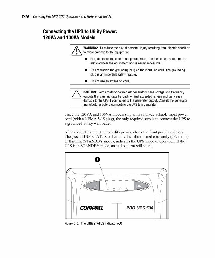
Since the 120VA and 100VA models ship with a non-detachable input powercord (with a NEMA 5-15 plug), the only required step is to connect the UPS toa grounded utility wall outlet.
After connecting the UPS to utility power, check the front panel indicators.The green LINE STATUS indicator, either illuminated constantly (ON mode)or flashing (STANDBY mode), indicates the UPS mode of operation. If theUPS is in STANDBY mode, an audio alarm will sound.
1
Figure 2-5. The LINE STATUS indicator (�)
Installation 2-11
IMPORTANT: When the UPS is connected to utility power, all receptacles willimmediately be energized regardless of the UPS operating mode selected (using the UPSON/STANDBY button).
IMPORTANT: If any of the indicators on the front panel are red (indicating an alarmcondition), press the TEST/ALARM RESET button to clear the red indicators. If this doesnot clear the red indicators, see Chapter 6, “Troubleshooting.”
IMPORTANT: If the UPS does not include a power cord that is suitable for the application,contact an authorized Compaq service representative to obtain the appropriate powercord.
For more information on the front panel indicators and controls, see Chapter 3,“Operation.”
Connecting the UPS to Utility Power:230VA Model
WARNING: To reduce the risk of personal injury resulting from electric shock orto avoid damage to the equipment:
� Plug the input line cord into a grounded (earthed) electrical outlet that isinstalled near the equipment and is easily accessible.
� Do not disable the grounding plug on the input line cord. The groundingplug is an important safety feature.
� Do not use an extension cord.
CAUTION: Some motor-powered AC generators have voltage and frequencyoutputs that can fluctuate beyond nominal accepted ranges and can causedamage to the UPS if connected to the generator output. Consult the generatormanufacturer before connecting the UPS to a generator.
2-12 Compaq Pro UPS 500 Operation and Reference Guide
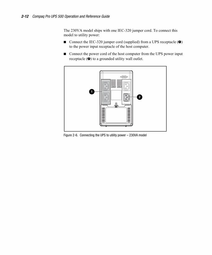
The 230VA model ships with one IEC-320 jumper cord. To connect thismodel to utility power:
� Connect the IEC-320 jumper cord (supplied) from a UPS receptacle (�)to the power input receptacle of the host computer.
� Connect the power cord of the host computer from the UPS power inputreceptacle (�) to a grounded utility wall outlet.
1
2
Figure 2-6. Connecting the UPS to utility power – 230VA model
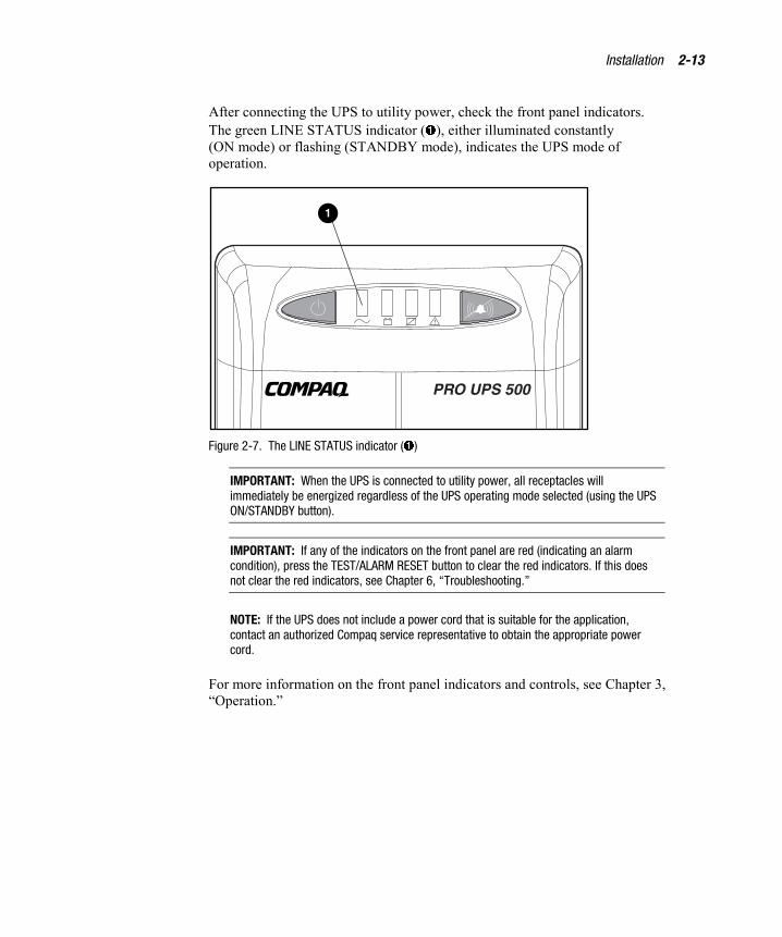
Installation 2-13
After connecting the UPS to utility power, check the front panel indicators.The green LINE STATUS indicator (�), either illuminated constantly(ON mode) or flashing (STANDBY mode), indicates the UPS mode ofoperation.
1
Figure 2-7. The LINE STATUS indicator (�)
IMPORTANT: When the UPS is connected to utility power, all receptacles willimmediately be energized regardless of the UPS operating mode selected (using the UPSON/STANDBY button).
IMPORTANT: If any of the indicators on the front panel are red (indicating an alarmcondition), press the TEST/ALARM RESET button to clear the red indicators. If this doesnot clear the red indicators, see Chapter 6, “Troubleshooting.”
NOTE: If the UPS does not include a power cord that is suitable for the application,contact an authorized Compaq service representative to obtain the appropriate powercord.
For more information on the front panel indicators and controls, see Chapter 3,“Operation.”

2-14 Compaq Pro UPS 500 Operation and Reference Guide
Completing the InstallationWith the UPS in STANDBY mode, allow the battery to charge before puttingthe UPS into service.
IMPORTANT: The battery will charge to 90% of their capacity within approximately4 hours. Compaq recommends allowing the battery to charge for 12 hours before usingthem to supply backup power to devices.
Installing Compaq Power ManagerPro UPS Software
Refer to Software Installation Instructions (insert included in the CDpackaging) for information on the installation requirements for the CompaqPower Manager Pro UPS software.
Selecting the UPS Operating Mode
Select the appropriate UPS operating mode using the ON/STANDBYbutton (�). For more information, see “Front Panel Controls” in Chapter 3.
The ON/STANDBY button is a momentary switch that toggles between twoUPS operating modes (ON and STANDBY). To toggle back and forthbetween the two operating modes, press and hold the ON/STANDBYbutton (�) for 2 seconds, until you hear a beep.
21
Figure 2-8. Selecting the UPS operating mode

Installation 2-15
“ON” Mode
� Function: ENABLES battery backup.
� UPS Conditions: The UPS battery is charging. Power is ON at the UPSreceptacles. The green LINE STATUS indicator (�) is illuminated.
� Setting Advantages: Provides battery backup in the event of a blackoutor brownout.
“STANDBY” Mode
� Function: DISABLES battery backup.
� UPS Conditions: The UPS battery is charging. Power is ON at the UPSreceptacles. The green LINE STATUS indicator (�) is flashing. TheUPS audio alarm is sounding once per minute.
� Setting Advantages: Continues to charge the battery when power ispresent, while turning OFF the inverter to prevent battery backupoperation when equipment is not in use.
CAUTION: When the UPS is in the STANDBY mode, the UPS will not providebattery backup during a blackout or brownout.
NOTE: The Compaq Pro UPS 500 can be used as a standalone power source when utilitypower is not present. For more information, see “Start-On-Battery Operation” inChapter 3.
The installation is now complete
� For information on operating the UPS, see Chapter 3, “Operation.”
� Use the Compaq website as an additional information source:http://www.compaq.com.
Chapter 3Operation
This chapter provides information on the following topics:
� Precautions to be observed when using the UPS
� Front panel overview
� Front panel controls
� ON/STANDBY button
� TEST/ALARM RESET button
� Front panel indicators and audio alarms
� Rear panel overview
� Rear panel features
3-2 Compaq Pro UPS 500 Operation and Reference Guide
Operation PrecautionsObserve these precautions when using the UPS.
WARNING: To reduce the risk of personal injury from earth conductor leakagecurrent:
� Do not operate a UPS that is disconnected from the utility power source.
� Disconnect protected devices from the UPS before disconnecting the UPSfrom utility power.
� Use the TEST/ALARM RESET button to test the battery rather thanunplugging the UPS. For more information, see “Initiating a UPS Self-Test,”in this chapter.

Operation 3-3
Front Panel OverviewCompaq Pro UPS 500 models feature the same front panel, which includesindicator lights that alert you to UPS operating conditions and controlsrequired to:
� Select the UPS operating mode.
� Initiate a self-test of the UPS battery.
� Silence an audio alarm.
5 62 3 41
Figure 3-1. Front panel indicators and button controls
Symbol
� ON/STANDBY button
� LINE STATUS indicator
� ON BATTERY indicator
� BATTERY LOW/REPLACE indicator
� UPS LOAD indicator
� TEST/ALARM RESET button
3-4 Compaq Pro UPS 500 Operation and Reference Guide
Front Panel Controls
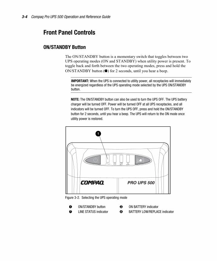
ON/STANDBY Button
The ON/STANDBY button is a momentary switch that toggles between twoUPS operating modes (ON and STANDBY) when utility power is present. Totoggle back and forth between the two operating modes, press and hold theON/STANDBY button (�) for 2 seconds, until you hear a beep.
IMPORTANT: When the UPS is connected to utility power, all receptacles will immediatelybe energized regardless of the UPS operating mode selected by the UPS ON/STANDBYbutton.
NOTE: The ON/STANDBY button can also be used to turn the UPS OFF. The UPS batterycharger will be turned OFF. Power will be turned OFF at all UPS receptacles, and allindicators will be turned OFF. To turn the UPS OFF, press and hold the ON/STANDBYbutton for 2 seconds, until you hear a beep. The UPS will return to the ON mode onceutility power is restored.
1
Figure 3-2. Selecting the UPS operating mode
� ON/STANDBY button � ON BATTERY indicator� LINE STATUS indicator � BATTERY LOW/REPLACE indicator
Operation 3-5
“ON” Mode
� Function: ENABLES battery backup.
� UPS Conditions: The UPS battery is charging. Power is ON at the UPSreceptacles. The green LINE STATUS indicator (�) is illuminated.
� Setting Advantages: Provides battery backup in the event of a blackoutor brownout.
“STANDBY” Mode
� Function: DISABLES battery backup.
� UPS Conditions: The UPS battery is charging. Power is ON at the UPSreceptacles. The green LINE STATUS indicator (�) is flashing. TheUPS audio alarm is sounding once per minute.
� Setting Advantages: Continues to charge the battery when power ispresent, while turning OFF the inverter to prevent battery backupoperation when equipment is not in use.
CAUTION: When the UPS is in the STANDBY mode, the UPS will not providebattery backup during a blackout or brownout.
Other Modes of Operation
The ON and STANDBY UPS operating modes can be manually selected bythe user. There are, however, three additional UPS operating modes whichoccur automatically.
� Battery Operate Mode: While the UPS is in the ON mode and ablackout or severe brownout occurs, the UPS will automatically switchto battery power. The yellow ON BATTERY indicator (�) will beilluminated. AC power from the UPS battery is available at theBattery-and-Surge-Protected receptacles. AC power is not available atthe Surge-Protected receptacles. An audio alarm sounds (the alarm canbe muted).
� Automatic Shutdown Mode: When the UPS detects that less than2 minutes of battery power is available during a prolonged blackout orbrownout at approximately full load, the UPS will automatically enterAutomatic Shutdown mode. The red BATTERY LOW/REPLACEindicator (�) is illuminated. Less than 2 minutes of AC Power isavailable at the Battery-and-Surge-Protected receptacles. Anon-silenceable alarm sounds as the UPS prepares for shutdown.

3-6 Compaq Pro UPS 500 Operation and Reference Guide
� Automatic Voltage Regulation (Boost) Mode: When an undervoltageoccurs, the UPS will automatically correct the voltage level withoutswitching to battery power. When this occurs, the UPS may emit aclicking sound. The more the UPS adjusts the voltage level, the morethe UPS will click. This is a normal, automatic operation of the UPS,and no action is required.
Start-On-Battery Operation
Compaq Pro UPS 500 models have special circuitry that allows them to beused as standalone power sources when utility power is not present. TheBattery-and-Surge-Protected receptacles will supply AC power for the timelimits of the internal battery. The Surge-Protected receptacles, however, willnot supply AC power until utility power returns.
� To perform the UPS Start-On-Battery operation when you first plug inthe unit and power is not present, momentarily press the ON/STANDBYbutton (�) and release the button after the UPS emits a beep.
� To perform the UPS Start-On-Battery operation when the unit isplugged in and operating in the STANDBY mode, press theON/STANDBY button (�) and release the button after the UPS emits abeep; press the ON/STANDBY button a second time and release thebutton after the UPS emits a beep.
1
Figure 3-3. Selecting Start-On-Battery Operation using the ON/STANDBYbutton (�)
Operation 3-7
WARNING: To reduce the risk of personal injury resulting from electric shock orto avoid damage to the equipment:
� Plug the input line cord into a grounded (earthed) electrical outlet that isinstalled near the equipment and is easily accessible.
� Do not disable the grounding plug on the input line cord. The groundingplug is an important safety feature.
� Do not use an extension cord.
IMPORTANT:
� Performing a UPS Start-On-Battery with load present requires more power thankeeping an already-operating load running. You may not be able to start as large aload as usual when performing a UPS Start-On-Battery using theCompaq Pro UPS 500.
� After performing a UPS Start-On-Battery, the UPS drains the charge on the battery;runtime is very limited.
� If utility power returns, power WILL BE SUPPLIED at the Surge-Protected receptaclesif the unit is connected to the utility outlet.
3-8 Compaq Pro UPS 500 Operation and Reference Guide
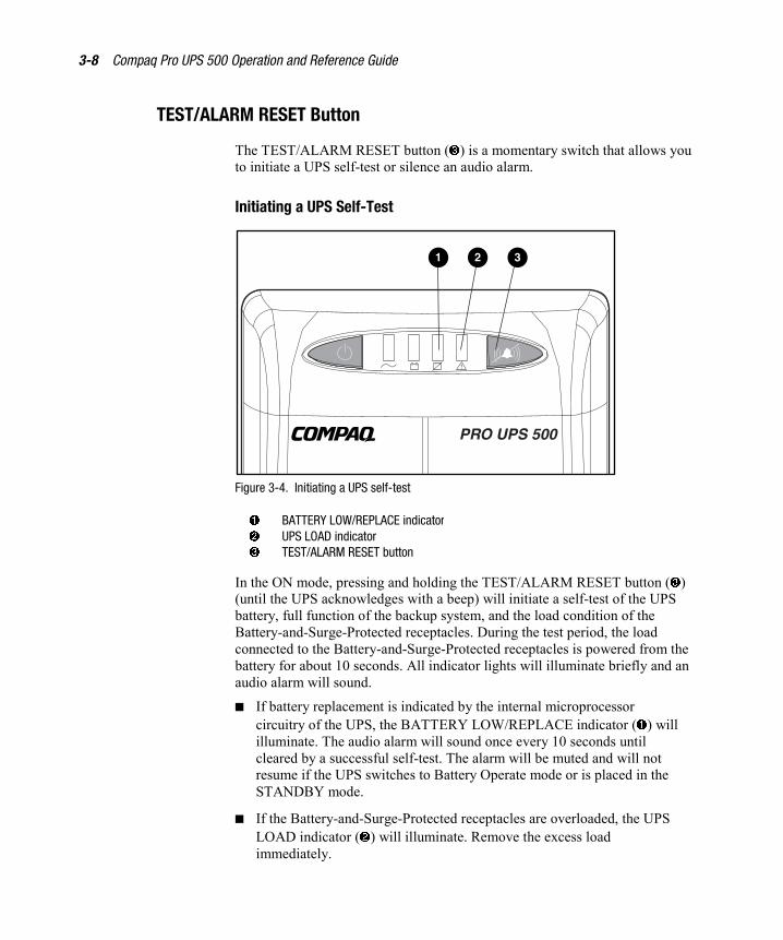
TEST/ALARM RESET Button
The TEST/ALARM RESET button (�) is a momentary switch that allows youto initiate a UPS self-test or silence an audio alarm.
Initiating a UPS Self-Test
2 31
Figure 3-4. Initiating a UPS self-test
� BATTERY LOW/REPLACE indicator� UPS LOAD indicator� TEST/ALARM RESET button
In the ON mode, pressing and holding the TEST/ALARM RESET button (�)(until the UPS acknowledges with a beep) will initiate a self-test of the UPSbattery, full function of the backup system, and the load condition of theBattery-and-Surge-Protected receptacles. During the test period, the loadconnected to the Battery-and-Surge-Protected receptacles is powered from thebattery for about 10 seconds. All indicator lights will illuminate briefly and anaudio alarm will sound.
� If battery replacement is indicated by the internal microprocessorcircuitry of the UPS, the BATTERY LOW/REPLACE indicator (�) willilluminate. The audio alarm will sound once every 10 seconds untilcleared by a successful self-test. The alarm will be muted and will notresume if the UPS switches to Battery Operate mode or is placed in theSTANDBY mode.
� If the Battery-and-Surge-Protected receptacles are overloaded, the UPSLOAD indicator (�) will illuminate. Remove the excess loadimmediately.

Operation 3-9
CAUTION: Do not initiate the self-test procedures while critical computer orload functions are being performed.
IMPORTANT: For the Compaq Pro UPS 500, the only method of checking the battery andcircuitry functionality is by performing a UPS self-test on a routine basis.
Silencing an Audio Alarm
The UPS may sound an audio alarm to warn the user that an alarm conditionexists. To silence the alarm, momentarily press and release the TEST/ALARMRESET button (�).
1
Figure 3-5. Silencing an audio alarm using theTEST/ALARM RESET button (�)
IMPORTANT:
� While an audio alarm may be silenced, the condition that caused the alarm may stillexist. See Chapter 6, “Troubleshooting,” for information on procedures if the UPSdetects an alarm condition.
� When the UPS is operating from the battery and battery power is nearly depleted,the alarm cannot be silenced. This alerts the user to immediately shut downconnected equipment.

3-10 Compaq Pro UPS 500 Operation and Reference Guide
Front Panel Indicators and Audio AlarmsThe front panel indicators signal the status of the UPS.
LINE STATUS Indicator (Green)
The LINE STATUS indicator illuminates whenever the UPS is connected toacceptable AC utility line power.
While the UPS is in the ON mode, the LINE STATUS indicator will remainconstantly illuminated to indicate that battery backup is enabled and will beavailable at the Battery-and-Surge-Protected receptacles in the event of ablackout or brownout.
While the UPS is in the STANDBY mode, this indicator will flash (and analarm will sound once per minute) to indicate that battery backup is disabledand will not be available at the Battery-and-Surge-Protected receptacles in theevent of a blackout or brownout. The alarm can be silenced by momentarilypressing the TEST/ALARM RESET button.
NOTE: If the UPS is disconnected from utility power, the UPS will return to the mode (ONor STANDBY) the UPS was in when power was lost.
ON BATTERY Indicator (Yellow)
The ON BATTERY indicator illuminates whenever the UPS is operating frominternal battery. After 10 seconds of continuous battery operation, an audioalarm will sound consisting of 4 short beeps, followed by an 8-second pause.The alarm can be silenced by momentarily pressing the TEST/ALARMRESET button. When the battery is nearly depleted, the ON BATTERY andBATTERY LOW/REPLACE indicators will both be illuminated and the alarmwill resume (and cannot be silenced) to alert the user to immediately shutdown connected equipment.
Operation 3-11
BATTERY LOW/REPLACE Indicator (Red)
The BATTERY LOW/REPLACE indicator illuminates when the internalprocessor detects a low or weak battery.
The BATTERY LOW/REPLACE indicator will illuminate constantly toindicate low battery charge. This indicator will flash, after a self-test isinitiated, to indicate the need to replace the battery. An audio alarm will soundonce per 10 seconds. The alarm can be silenced by momentarily pressing theTEST/ALARM RESET button. If the BATTERY LOW/REPLACE indicatorflashes, allow the UPS to recharge for 12 hours and repeat the self-test. See“Initiating a UPS Self-Test” in this chapter.
UPS LOAD Indicator (Red)
The UPS LOAD indicator illuminates automatically under the followingconditions: utility power is absent, the UPS is operating from the battery, andan overload condition exists. This indicator flashes when the UPS detectsoverload conditions of 100 percent of rated load. The UPS will shut down andthe indicator will illuminate continuously if the UPS load exceeds 100 percentof rating. Remove excess load immediately and initiate a self-test to clear theshutdown latch.
You can detect the presence of an overload by conducting a self-test. See“Initiating a UPS Self-Test” in this chapter.

3-12 Compaq Pro UPS 500 Operation and Reference Guide
Rear Panel Overview Compaq Pro UPS 500 models have the following rear panel configurations:
WARNING: To reduce the risk of personal injury resulting from electric shock,do not open the UPS for any reason. There are no user-serviceable parts insidethe UPS.
25
6
43
1
Figure 3-6. Rear panel configuration - 100VA and 120VA models
� Communications port � Battery compartment
� Noise and surge-protectedreceptacles
� Battery, noise, and surge-protectedreceptacles
� Non-detachable input powercord with NEMA 5-15 plug
� Phone/Fax Surge Protectors
Operation 3-13
5
4
3
1
2
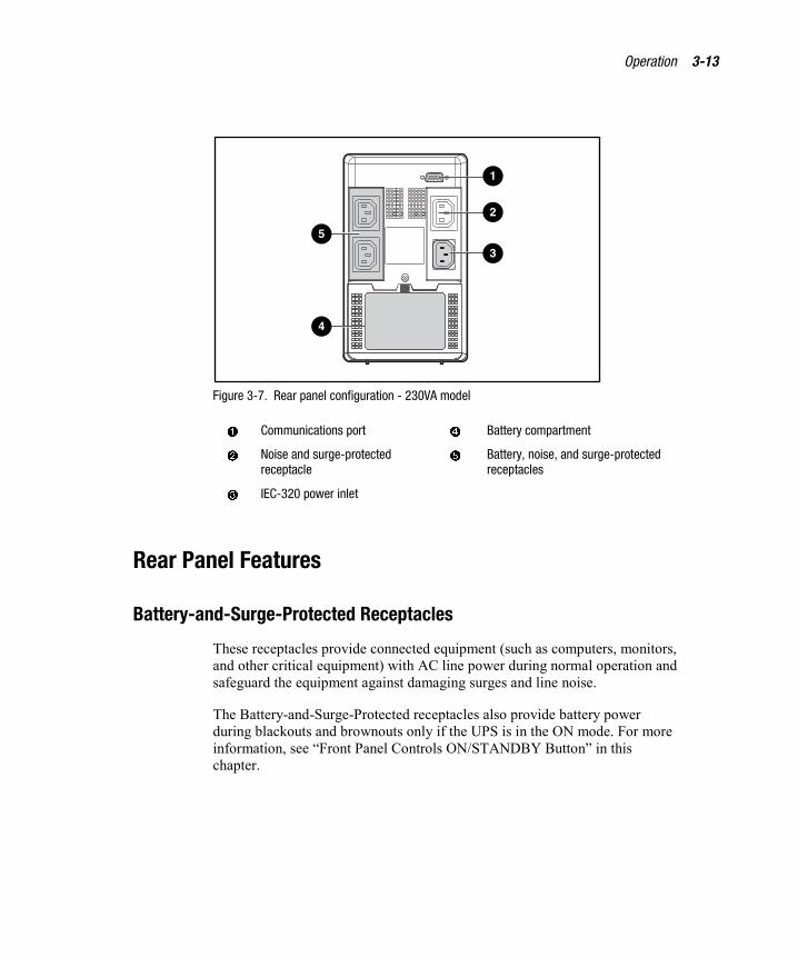
Figure 3-7. Rear panel configuration - 230VA model
� Communications port � Battery compartment
� Noise and surge-protectedreceptacle
� Battery, noise, and surge-protectedreceptacles
� IEC-320 power inlet
Rear Panel Features
Battery-and-Surge-Protected Receptacles
These receptacles provide connected equipment (such as computers, monitors,and other critical equipment) with AC line power during normal operation andsafeguard the equipment against damaging surges and line noise.
The Battery-and-Surge-Protected receptacles also provide battery powerduring blackouts and brownouts only if the UPS is in the ON mode. For moreinformation, see “Front Panel Controls ON/STANDBY Button” in thischapter.
3-14 Compaq Pro UPS 500 Operation and Reference Guide
RJ11 Phone/Fax Surge Protector
Select Compaq Pro UPS 500 models include a Phone/Fax Surge Protector tosafeguard communications equipment (such as a fax machine or a modem)from spikes and surges from transients present on telephone lines.
Communications Port
The communications port connects the UPS to any computer or workstation.Use the communications port with Compaq Power Manager Pro UPS softwareto enable automatic shutdown and power management functionality.
Surge-Protected Receptacle(s)
These receptacles provide connected equipment with AC line power duringnormal operation. They also safeguard equipment against damaging surges andline noise. Connect non-critical peripherals to these receptacles.
The Surge-Protected receptacles will not provide battery backup duringblackouts and brownouts. They always supply AC power, when present,regardless of the UPS operating mode selected by the ON/STANDBY button.
AC Power Input Receptacle (230VA Model Only)
This receptacle accepts a detachable IEC-320 power cord. For moreinformation, see Chapter 2, “Installation.”
Battery Replacement Door
Under normal conditions, the battery supplied in the UPS will last severalyears. Only qualified service personnel should perform battery replacement.

Chapter 4Software
This chapter provides information on the following topics:
� Software overview
� Software functions
� Configuration parameters
� Installation procedures
4-2 Compaq Pro UPS 500 Operation and Reference Guide
Software OverviewCompaq Power Manager Pro UPS software is a web-based interface. Usingeither Netscape Navigator 3.0 or later, or Microsoft Internet Explorer 4.0 orlater, system administrators can monitor and manage power being supplied byUPS units.
Software FunctionsCompaq Power Manager Pro UPS software performs the following functions:
� Displays UPS status.
� Manages orderly shutdown of operating systems when an extendedutility power failure occurs.
� Executes messaging functions to operators, system administrators, andusers.
Displaying UPS Status
View the status of any UPS on the network, including:� UPS communications.
� Line state.
� Operating system shutdown countdown.
� Battery state.
� Battery capacity.
� Input voltage state.
� Load state.
� UPS self-test results.
� Event log summary.
Software 4-3
UPS Control Functions
Perform the following UPS control functions, using the software securityfeatures to:
� Protect access.
� Execute a UPS self-test.
� Shut down the operating system and UPS.
Configuration ParametersSystem administrators and operators can configure Compaq Power ManagerPro UPS software parameters through the web-based interface, including:
� Communications setting.
� Poll rate
� Broadcast settings.
� Wait time before broadcasting message
� Enable/disable broadcasting
� Shutdown settings.
� Configured time delay before system shut down when on battery
� Configured time delay before system shut down due to low battery
� Enable/disable shutdown
� Security settings.
� Password protection
� Enable/disable password
4-4 Compaq Pro UPS 500 Operation and Reference Guide
Installation ProceduresTo install Compaq Power Manager Pro UPS software:
1. Install Compaq Pro UPS 500 models. (For detailed installationinstructions, please see Chapter 2, “Installation,” or refer to the QuickInstallation Guide for Compaq Pro UPS 500, supplied with the UPSkit.)NOTE: Select Compaq NeoServers have UPS power management software preinstalled.Some NeoServer customers may not need to install Compaq Power Manager Pro UPSsoftware. Please see the NeoServer documentation included with the NeoServer unit forspecific power management software installation requirements.
2. For Novell NetWare, log in to the NetWare system, using an accountwith administrative privileges, on a client machine running MicrosoftWindows with a drive mapped to the SYS: volume on the targetNetWare server.
3. Insert the CD-ROM into the drive. If your operating system has theautomatic installation feature enabled, the Install Wizard startsautomatically. (See “Installation Wizard Notification” in this chapter.)
IMPORTANT: When installing Compaq Power Manager Pro UPS software on a NetWaresystem, the CD should be place in the client workstation.
For systems without automatic installation, select the CD drive icon inthe directory list (Drive D, for example) and double-click SETUP.EXEin the root directory.
4. Follow the Install Wizard instructions to set installation andconfiguration options.
Software 4-5
Installation Wizard Notification
Compaq Power Manager Pro UPS software takes advantage of the MicrosoftAutoPlay feature. To install Compaq Power Manager Pro UPS software usingthis Install Wizard, follow the steps below:
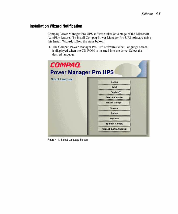
1. The Compaq Power Manager Pro UPS software Select Language screenis displayed when the CD-ROM is inserted into the drive. Select thedesired language.
Figure 4-1. Select Language Screen

4-6 Compaq Pro UPS 500 Operation and Reference Guide
2. After a language is selected, the Compaq Power Manager Pro UPSsoftware Option screen will display. Select the Install Software button.
Figure 4-2. Option Screen

Software 4-7
3. From the Installation Selection screen, select the desired application toinstall.
Figure 4-3. Installation Selection screen
4. Follow the Install Wizard instructions to set installation andconfiguration options.
For detailed installation and configuration requirements and procedures andusage options, please see the README.TXT file on the Compaq PowerManager Pro UPS Software and Documentation CD (included with the UPSkit).

Chapter 5Battery Maintenance
This chapter provides information on the following topics:
� Battery precautions
� Charging the battery
� When to replace the battery
� Pre-Failure Battery Warranty
� Obtaining a new battery
� Care and storage of batteries
� Disposing of used batteries

5-2 Compaq Pro UPS 500 Operation and Reference Guide
Battery PrecautionsThere are no user-serviceable parts to the Compaq Pro UPS 500. Do not openthe UPS for any reason. Contact an authorized Compaq service provider.
WARNING: There is a risk of personal injury from the hazardous energy levelsassociated with UPS batteries. The maintenance and replacement of batteriesmust be carried out by qualified service personnel who understand theprocedures, hazards, and precautions involved.
WARNING: The UPS contains a sealed lead-acid battery. To reduce the risk offire or chemical burns, Compaq authorized service personnel must take thefollowing precautions:
� Set the UPS on a flat, level surface and unplug the UPS.
� Remove watches, rings, or other metal objects.
� Use tools with insulated handles.
� Do not attempt to recharge the battery.
� Battery replacement is to be performed only by a Compaq authorizedservice provider using the Compaq spare designated for this product.
� Do not disassemble, crush, puncture, short external contacts, or dispose ofthe battery in fire or water.
Charging the BatteryThe UPS automatically charges the battery while the UPS is connected toutility power at nominal voltage levels. No user intervention is required whilethe UPS is in use.
For information on keeping the battery charged while the UPS is in extendedstorage, see “Care and Storage of Batteries,” in this chapter.
Battery Maintenance 5-3
When to Replace the Battery
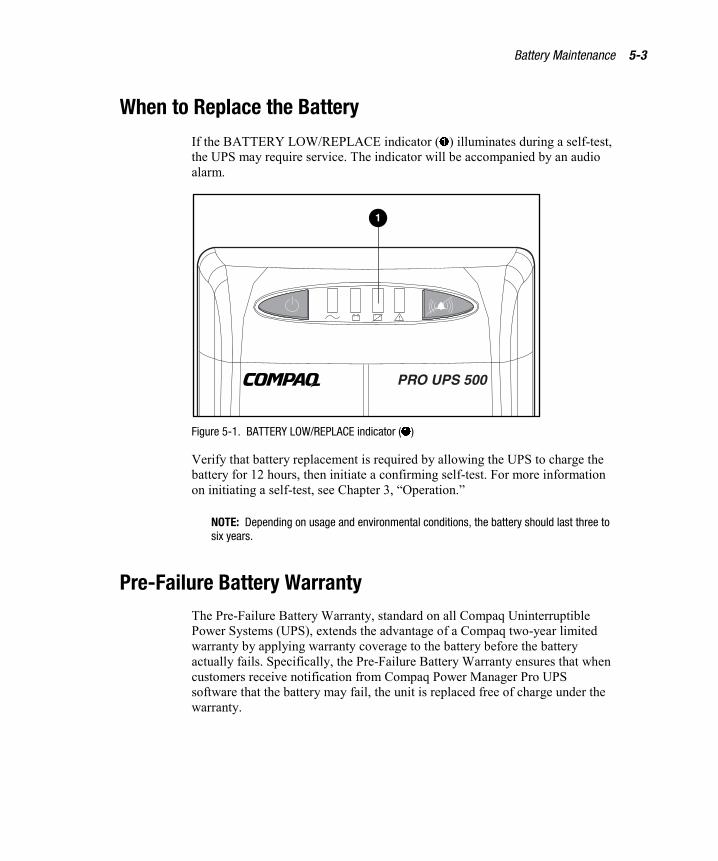
If the BATTERY LOW/REPLACE indicator (�) illuminates during a self-test,the UPS may require service. The indicator will be accompanied by an audioalarm.
1
Figure 5-1. BATTERY LOW/REPLACE indicator (�)
Verify that battery replacement is required by allowing the UPS to charge thebattery for 12 hours, then initiate a confirming self-test. For more informationon initiating a self-test, see Chapter 3, “Operation.”
NOTE: Depending on usage and environmental conditions, the battery should last three tosix years.
Pre-Failure Battery WarrantyThe Pre-Failure Battery Warranty, standard on all Compaq UninterruptiblePower Systems (UPS), extends the advantage of a Compaq two-year limitedwarranty by applying warranty coverage to the battery before the batteryactually fails. Specifically, the Pre-Failure Battery Warranty ensures that whencustomers receive notification from Compaq Power Manager Pro UPSsoftware that the battery may fail, the unit is replaced free of charge under thewarranty.

5-4 Compaq Pro UPS 500 Operation and Reference Guide
Compaq maintains the highest standards in the industry, as evidenced by theCompaq Pre-Failure Battery Warranty. The Pre-Failure Battery Warranty isbeneficial in at least two significant ways:
� Reduced total cost of ownership
� Reduced downtime
Obtaining a New BatteryContact an authorized Compaq service provider when the BATTERYLOW/REPLACE indicator (�) illuminates during the confirming self-test,indicating that a new battery will be required.
Care and Storage of BatteriesTo maximize the life of the battery:
� Minimize the amount of time the UPS is using battery power.
� Keep the area around the UPS clean and dust-free. If the environment isvery dusty, clean the outside of the UPS regularly with a vacuumcleaner.
� Maintain the ambient temperature at 25oC (77oF).
� If storing a UPS for an extended period, recharge the battery every sixmonths:
� Connect the UPS to utility power.
� Allow the UPS to charge the battery for 12 hours.
Disposing of Used BatteriesReplacement equipment includes the instructions and packaging required toreturn used batteries/units to the appropriate location for disposal.
Do not dispose of used batteries with general office or householdwaste. Return the used module for proper disposal to either:
� Compaq, authorized Compaq Partners, or their agents.
� A recycling center that meets all local environmentalstandards.

Chapter 6Troubleshooting
This chapter provides information on the following topics:
� Troubleshooting during UPS start
� Troubleshooting after UPS start
� Repairing the UPS

6-2 Compaq Pro UPS 500 Operation and Reference Guide
Troubleshooting During UPS StartIf problems occur when starting the Compaq Pro UPS 500, select theappropriate symptom for possible causes and suggested actions.
Table 6-1Troubleshooting Guide (UPS Start)
Symptom Possible Cause Suggested Action
UPS power cord disconnected. Connect power cord.Indicators:none
Alarm:none
No utility power. Contact a qualifiedelectrician to check powerat the utility powerreceptacle.
If desired, the UPS can beused as a stand-alonepower source. See “Start-On-Battery Operation” inChapter 3.
Battery voltage is low because the UPShas been stored for an extended periodof time without charging.
Indicators:BATTERYLOW/REPLACE
LINE STATUS
Alarm:none
Battery voltage is low because UPSsupported a load (and performedshutdown) during a blackout.
Allow the UPS to chargethe battery for 12 hours.Initiate a self-test. Ifindicators illuminate again,replace the battery.
Troubleshooting 6-3
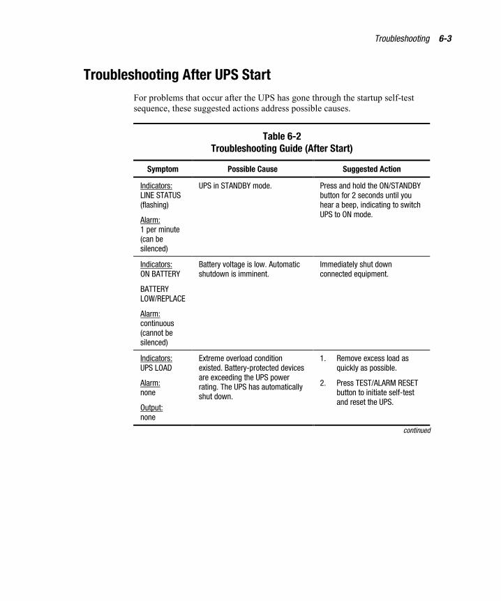
Troubleshooting After UPS StartFor problems that occur after the UPS has gone through the startup self-testsequence, these suggested actions address possible causes.
Table 6-2Troubleshooting Guide (After Start)
Symptom Possible Cause Suggested Action
Indicators:LINE STATUS(flashing)
Alarm:1 per minute(can besilenced)
UPS in STANDBY mode. Press and hold the ON/STANDBYbutton for 2 seconds until youhear a beep, indicating to switchUPS to ON mode.
Indicators:ON BATTERY
BATTERYLOW/REPLACE
Alarm:continuous(cannot besilenced)
Battery voltage is low. Automaticshutdown is imminent.
Immediately shut downconnected equipment.
Indicators:UPS LOAD
Alarm:none
Output:none
Extreme overload conditionexisted. Battery-protected devicesare exceeding the UPS powerrating. The UPS has automaticallyshut down.
1. Remove excess load asquickly as possible.
2. Press TEST/ALARM RESETbutton to initiate self-testand reset the UPS.
continued

6-4 Compaq Pro UPS 500 Operation and Reference Guide
Table 6-2Troubleshooting Guide (After Start) continued
Symptom Possible Cause Suggested Action
Indicators:UPS LOAD(flashing)
ON BATTERY(continuous)
Alarm:1 per 10seconds (canbe silenced)
Output:available
Battery-protected devices areloaded to the maximum UPSpower rating.
Reduce load on UPS as quicklyas possible until indicatorsextinguish.
Indicators:LINE STATUS
BATTERYLOW/REPLACE
Alarm:none
Battery voltage is low, but linepower is present and the battery ischarging.
No action is required.
Indicators:LINE STATUS
BATTERYLOW/REPLACE(flashing)
Alarm:1 per 10seconds (canbe silenced)
Battery has failed a UPS self-test,indicating low voltage or a weakbattery.
1. Press TEST/ALARM RESETbutton to silence alarm.
2. Allow battery to charge for12 hours, then initiate asecond self-test. IfBATTERY LOW/REPLACEindicator illuminates again,arrange for batteryreplacement.
Repairing the UPSThe UPS has no user-serviceable parts. All repairs to the UPS, includingbattery replacement, must be carried out by Compaq or a Compaq authorizedservice provider.

Appendix ARegulatory Compliance Notices
Federal CommunicationsCommission Notice
Part 15 of the Federal Communications Commission (FCC) Rules andRegulations has established Radio Frequency (RF) emission limits to providean interference-free radio frequency spectrum. Many electronic devices,including computers, generate RF energy incidental to their intended functionand are, therefore, covered by these rules. These rules place computers andrelated peripheral devices into two classes, A and B, depending upon theirintended installation. Class A devices are those that may reasonably beexpected to be installed in a business or commercial environment. Class Bdevices are those that may reasonably be expected to be installed in aresidential environment (that is, personal computers). The FCC requiresdevices in both classes to bear a label indicating the interference potential ofthe device as well as additional operating instructions for the user.
All Compaq Pro UPS 500 models are Class B devices.
Class B Equipment
This equipment has been tested and found to comply with the limits for aClass B digital device, pursuant to Part 15 of the FCC Rules. These limits aredesigned to provide reasonable protection against harmful interference in aresidential installation. This equipment generates, uses, and can radiate radiofrequency energy and, if not installed and used in accordance with the
A-2 Compaq Pro UPS 500 Operation and Reference Guide
instructions, may cause harmful interference to radio communications.However, there is no guarantee that interference will not occur in a particularinstallation. If this equipment does cause harmful interference to radio ortelevision reception, which can be determined by turning the equipment offand on, the user is encouraged to try to correct the interference by one or moreof the following measures:
� Reorient or relocate the receiving antenna.
� Increase the separation between the equipment and receiver.
� Connect the equipment into an outlet on a circuit different from that towhich the receiver is connected.
� Consult the dealer or an experienced radio or television technician forhelp.
Declaration of Conformity for Products Markedwith the FCC logo - United States Only
This device complies with Part 15 of the FCC Rules. Operation is subject tothe following two conditions: (1) this device may not cause harmfulinterference, and (2) this device must accept any interference received,including interference that may cause undesired operation.
For questions regarding your product, contact:
Compaq Computer CorporationP. O. Box 692000, Mail Stop 530113Houston, Texas 77269-2000
or call 1-800-652-6672 (1-800-OK-COMPAQ1).
For questions regarding this FCC declaration, contact:
Compaq Computer CorporationP. O. Box 692000, Mail Stop 510101Houston, Texas 77269-2000
or call (281) 514-3333.
To identify this product, refer to the part, series, or model number found on theproduct.
1 For continuous quality improvement, calls may be recorded or monitored.

Regulatory Compliance Notices A-3
Modifications
The FCC requires the user to be notified that any changes or modificationsmade to this device that are not expressly approved by Compaq ComputerCorporation may void the user's authority to operate the equipment.
Cables
Connections to this device must be made with shielded cables with metallicRFI/EMI connector hoods in order to maintain compliance with FCC Rulesand Regulations.
FCC Part 68 Notice
If the Fax Modem Protector causes harm to the telephone network, theTelephone Company may temporarily discontinue your service. If possible,they will provide advance notification. If advance notice is not practical,notification will be provided as soon as possible. You will be advised of yourright to file a complaint with the FCC. The Telephone Company may makechanges in its facilities, equipment, operations or procedures that could affectthe proper operation of your equipment. If the Telephone Company does,advance notice will be given to provide an opportunity to maintainuninterrupted service. If trouble with this equipment is experienced, FaxModem Protector, please contact Compaq for repair/warranty information. TheTelephone Company may request that the equipment be disconnected from thenetwork until the problem has been corrected or until the equipment is notmalfunctioning. There are no repairs that can be made by the customer to theFax Modem Protector. This equipment may not be used on coin serviceprovided by the Telephone Company. Connection to party lines is subject tostate tariffs. (Contact the state public utility commission or corporationcommission for information.)
Canadian Notice (Avis Canadien)
Class B Equipment
This Class B digital apparatus meets all requirements of the CanadianInterference-Causing Equipment Regulations.
Cet appareil numérique de la classe B respecte toutes les exigences duRèglement sur le matériel brouilleur du Canada.

A-4 Compaq Pro UPS 500 Operation and Reference Guide
European Union NoticeProducts with the CE Marking comply with both the EMC Directive(89/336/EEC) and the Low Voltage Directive (73/23/EEC) issued by theCommission of the European Community.
Compliance with these directives implies conformity to the followingEuropean Norms (in brackets are the equivalent international standards):
� EN55022 (CISPR 22) - Electromagnetic Interference
� EN50082-1 (IEC801-2, IEC801-3, IEC801-4) - ElectromagneticImmunity
� EN60950 (IEC950) - Product Safety
Japanese NoticeJuly 14 version
Regulatory Compliance Notices A-5
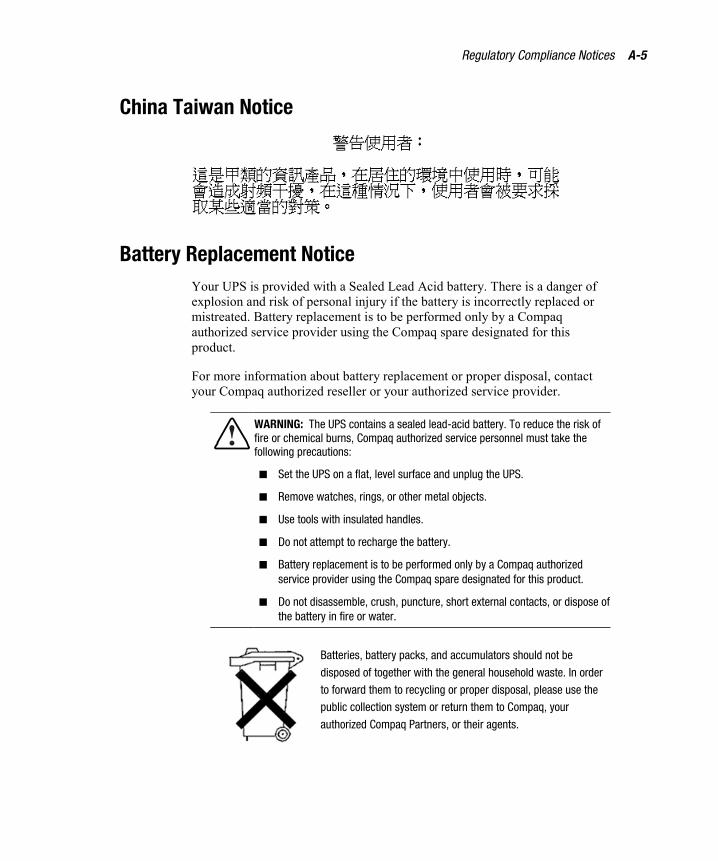
China Taiwan Notice
Battery Replacement Notice Your UPS is provided with a Sealed Lead Acid battery. There is a danger ofexplosion and risk of personal injury if the battery is incorrectly replaced ormistreated. Battery replacement is to be performed only by a Compaqauthorized service provider using the Compaq spare designated for thisproduct.
For more information about battery replacement or proper disposal, contactyour Compaq authorized reseller or your authorized service provider.
WARNING: The UPS contains a sealed lead-acid battery. To reduce the risk offire or chemical burns, Compaq authorized service personnel must take thefollowing precautions:
� Set the UPS on a flat, level surface and unplug the UPS.
� Remove watches, rings, or other metal objects.
� Use tools with insulated handles.
� Do not attempt to recharge the battery.
� Battery replacement is to be performed only by a Compaq authorizedservice provider using the Compaq spare designated for this product.
� Do not disassemble, crush, puncture, short external contacts, or dispose ofthe battery in fire or water.
Batteries, battery packs, and accumulators should not be
disposed of together with the general household waste. In order
to forward them to recycling or proper disposal, please use the
public collection system or return them to Compaq, your
authorized Compaq Partners, or their agents.

Appendix BSpecifications
This appendix provides specifications that apply to the Compaq Pro UPS 500:
� Physical specifications
� Input specifications
� Output specifications
� Battery specifications
� Environmental specifications
B-2 Compaq Pro UPS 500 Operation and Reference Guide
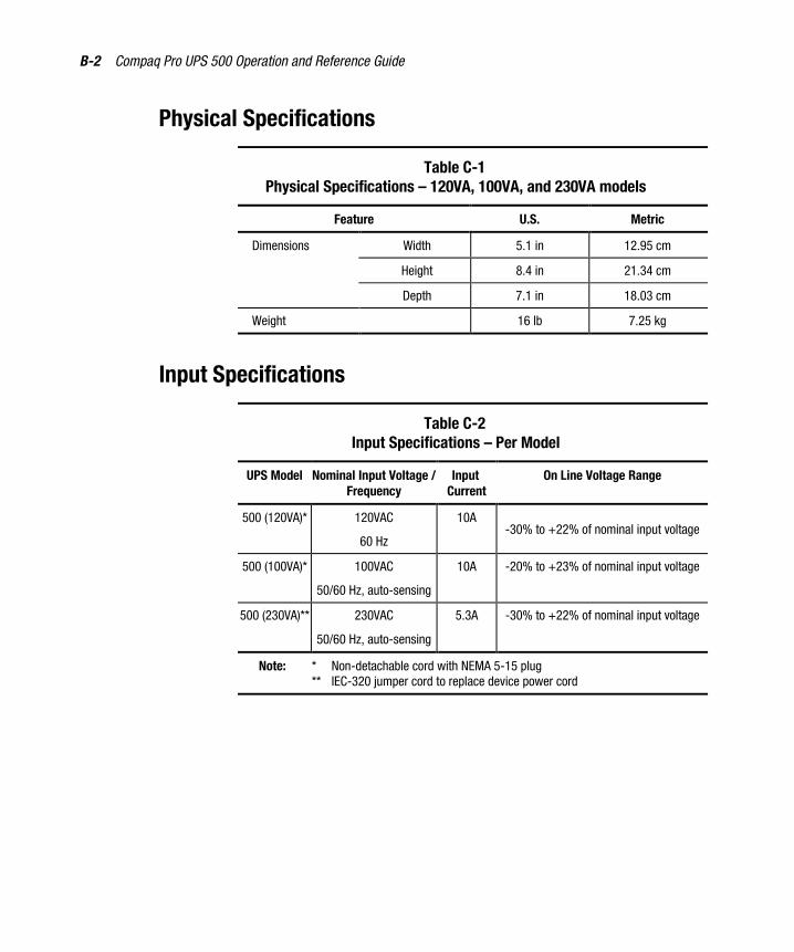
Physical Specifications
Table C-1Physical Specifications – 120VA, 100VA, and 230VA models
Feature U.S. Metric
Dimensions Width 5.1 in 12.95 cm
Height 8.4 in 21.34 cm
Depth 7.1 in 18.03 cm
Weight 16 lb 7.25 kg
Input Specifications
Table C-2Input Specifications – Per Model
UPS Model Nominal Input Voltage /Frequency
InputCurrent
On Line Voltage Range
500 (120VA)* 120VAC
60 Hz
10A-30% to +22% of nominal input voltage
500 (100VA)* 100VAC
50/60 Hz, auto-sensing
10A -20% to +23% of nominal input voltage
500 (230VA)** 230VAC
50/60 Hz, auto-sensing
5.3A -30% to +22% of nominal input voltage
Note: * Non-detachable cord with NEMA 5-15 plug** IEC-320 jumper cord to replace device power cord

Specifications B-3
Output Specifications
Table C-3Battery-and-Surge-Protected Output Specifications - Per Model
Output Receptacles
ModelCapacity
(VA/Watts) Battery-and-Surge-Protected
Surge-Protected
500 (120VA) 500 / 300 3 x 5-15R 3 x 5-15R
500 (100VA) 500 / 300 3 x 5-15R 3 x 5-15R
500 (230VA) 500 / 300 2 x IEC-320 (10A) 1 x IEC-320 (10A)
Table C-4Output Current Specifications - Per Model
Output Current
Model Battery-and-Surge-ProtectedReceptacles
Surge-Protected Receptacles
500 (120VA) 2.5A 7.25A
500 (100VA) 3A 5.6A
500 (230VA) 1.3A 7.25A

B-4 Compaq Pro UPS 500 Operation and Reference Guide
Output Specifications (continued)
Table C-5Output Specifications - 120VA, 100VA, and 230VA models
Source of Power Regulation
Automatic voltageregulated outputduring on lineoperation
Output is increased by 14% in thefollowing voltage ranges: 83V to 104V(120VA model); 80V to 91V (100VAmodel); 159V to 199V (230VA model)
Battery power output ±5% RMS
Feature Specification
Other Features On-line efficiency 96%
Transfer time 2-4 ms (typical)
Voltage wave shape Simulated sine wave
Surge suppression Up to 6,000V spikes at current levelsup to 27,000A. Spike suppressionstarts at voltages above nominal peakline values. Handles up to 240 joules(120VA and 100VA models) or340 joules (230VA model). Clampingresponse time: less than 1 ns. Spikesuppression in all three modes: Hot toNeutral, Hot to Ground, and Neutral toGround
Meets the requirements of UL 1449and ANSI C62.41 Category B (formerlyIEEE 587)
Noise filtering Full time EMI/RFI noise suppressionwith attenuation exceeding 40dB at1MHz
Phone/Fax SurgeProtection
(Available on selectmodels)
Clamping voltage: 235V peak ±10%.Response time: 5 ns. Peak transientinput voltage: 6Kv 10 ms. Single-linemodem/fax protection covers centertwo wires of RJ11 connection

Specifications B-5
Battery Specifications
Table C-6Battery Specifications - 120VA, 100VA, and 230VA models
Feature Specification
Type Sealed lead-acid; maintenance-free
Voltage Internal batteries - 12 VDC
Battery Recharge Rate(discharged with 50%load)
2 to 4 hours
Environmental Specifications
Table C-7Environmental Specifications - 120VA, 100VA, and 230VA models
Feature Specification
Operating temperature 0o to 40oC (32o to 104oF)
UL-tested at 25oC (77oF)
Relative humidity 0% to 95%; non-condensing
Operating altitude Up to 3000 m (10,000 ft) above sea level
Audible noise Less than 45 dBA
Index
Aalarm See audio alarm
Automatic Shutdownmode 3-6
audio alarmability to disable 3-9Battery Operate mode 3-5features 3-9how to respond 6-3silencing 3-3, 3-9
requirement to address alarmcondition 3-9
Automatic Shutdown mode 3-5alarm 3-6explained 3-5
Bbattery
care and storage See care andstorage of batteries
changingwarning on risk of personal
injury 5-2warning to use qualified service
personnel 5-2warnings on risk of fire or
burns 5-2charging 5-4
disposing See disposing ofused batteries
maintainingcare and storage 5-4warning on risk of personal
injury 5-2warning to use qualified service
personnel 5-2warnings on risk of fire or
burns 5-2new
when to obtain 5-4when to replace See when to
replace batteryBATTERY LOW/ALARM
indicator 3-11Automatic Shutdown
mode 3-5illuminated 3-5troubleshooting alarm
conditions 6-2Battery Operate mode 3-5
explained 3-5ON BATTERY indicator 3-5
Battery-and-Surge-Protectedreceptaclesfeatures 2-8illustrated 2-8plugging in equipment 2-8warning against connecting
laser printers 2-7

2 Compaq Pro UPS 500 Operation and Reference Guide
Ccare and storage of batteries 5-4
ambient temperature 5-4charging stored batteries 5-4preventive maintenance 5-4
changing battery 5-1charging the battery
after installation 2-14in storage 5-4
communications portconnecting to the host
computer 2-4caution against using other
communications cables 2-4connecting to the host
computer, illustrated 2-4features 1-6overview 1-6
Compaq Power Managementsoftwareconfiguration 4-3
Compaq Power Manager Pro UPSsoftwareobtaining information on
installationrequirements 2-2, 2-14
Compaq Pro UPS 500features 1-6front panel 1-3
illustrated 1-3models 1-2rear panels 1-4, 3-12
illustrated 1-4, 3-12connecting
devices to the UPS 2-7Phone/Fax Surge
Protector 2-5RS-232 communications
cable 2-4serial communications
cable 2-4UPS to utility power 2-10UPS/computer interface
cable 2-4
controls and indicatorsfront panel See front panel,
indicatorsconverting Watts to VA 2-6
Ddisposing of used batteries
instructions 5-4precautions to be observed 5-4
Ffeatures 1-6front panel
display See front panel,indicators
indicators 3-10, 3-13illustrated 1-3, 3-3
front panel display See front panel,indicatorsindicator colors 3-13
front panel indicatorsmeaning of colors 3-10
Gguarantee See warranties
Iindicators See front panel,
indicatorsinstalling a UPS
checking the load 2-7completing the
installation 2-14connecting the communications
port 2-4caution against using other
communications cables 2-4illustrated 2-4
connecting the devicesturning equipment off 2-7warning concerning laser
printers 2-7

Index 3
connecting the Phone/FaxSurge Protector 2-5
requirementshardware 2-2software 2-2tools 2-2
starting the UPS 2-7
LLINE STATUS indicator 3-10load
calculating total load(VA) 2-6
overload 2-6
Mmode of operation
Automatic Shutdownmode 3-5
Automatic Voltage Regulation(Boost mode) 3-6
Battery Operate mode 3-5ON mode 3-5STANDBY mode 3-5
OON BATTERY indicator 3-10
Battery Operate mode 3-5illuminated 3-5
ON mode 3-5Operating mode
selecting 3-3operating the UPS
BATTERY LOW/ALARMindicator illuminated 3-5
ON BATTERY indicatorilluminated 3-5
warning on earth leakagehazards 3-2
warning on operating whiledisconnected from utilitypower 3-2
overload
conditions and indicator 3-11starting a UPS Start-On-Battery
load 3-7overview
battery maintenance 5-1installation 2-1operating the UPS 3-1troubleshooting 6-1UPS 1-1
PPBX
connecting to a digitalPBX 2-5
Phone/Fax Surge Protectorconnecting 2-5features 1-7, 3-14
plugalways using three prong
grounded plug 2-7precaution against use of
adapters 2-7power cord
cords shipped with theUPS 2-10
requirement for additionalcord 2-11, 2-13
shipped with the UPS 2-2solution for additional
cord 2-11, 2-13powering down the UPS 3-4problems See troubleshooting
Rrear panels
features 1-4, 3-12illustrated 1-4, 3-12
reference materialCompaq Power Manager Pro
UPS software installationinstructions 2-2
4 Compaq Pro UPS 500 Operation and Reference Guide
Compaq Power ProductsSoftware ReferenceGuide 2-2
Compaq Pro UPS 500Operation and ReferenceGuide 2-2
repairing the UPS 6-4RJ11 Phone/Fax Surge
Protector See Phone/Fax SurgeProtector
Sself-test
audio alarm 3-8BATTERY LOW/ALARM
indicator 3-8initiating 3-8use of battery backup 3-8
softwareconfiguration 4-3functions explained 4-2overview 4-1using the UPS communication
port 2-4STANDBY mode 3-5
power supplied when utilitypower returns 3-7
Start-On-Battery 3-6starting 3-7
storage See care and storage ofbatteries
surge protectors, externalprecaution against use 2-7
Surge-Protected receptaclesfeatures 2-9illustrated 2-9plugging in equipment 2-9
TTEST/ALARM RESET button
initiating a self-test 3-8troubleshooting
after start 6-3during start 6-2
turning OFF the UPS 3-4
UUPS
turning OFF 3-4UPS kit contents
hardware 2-2reference material 2-2software 2-2
UPS/computer interface cableconnecting from the UPS to the
host computer 2-4
VVA rating
UPS and devices 2-6
Wwarranties
$25,000 Computer LoadProtection Guarantee 1-8
applicability 1-8limited warranty 1-8pre-failure battery 1-8, 5-3two-year limited 1-8
when to replace battery 5-3Error! Cannot open file referenced
on page 5