comparative analysis of modulation schemes using adaptive …
TRANSCRIPT

International Journal of Electronics Signals and Systems International Journal of Electronics Signals and Systems
Volume 2 Issue 1 Article 5
July 2012
COMPARATIVE ANALYSIS OF MODULATION SCHEMES USING COMPARATIVE ANALYSIS OF MODULATION SCHEMES USING
ADAPTIVE EQUALIZATION AS FADING MITIGATION TECHNIQUE ADAPTIVE EQUALIZATION AS FADING MITIGATION TECHNIQUE
SABITA NAHATA Department of Electronics Engineering, Indian School of Mines, Dhanbad, India, [email protected]
SUBRATA BHATTACHARYA Department of Electronics Engineering, Indian School of Mines, Dhanbad, India, [email protected]
Follow this and additional works at: https://www.interscience.in/ijess
Part of the Electrical and Electronics Commons
Recommended Citation Recommended Citation NAHATA, SABITA and BHATTACHARYA, SUBRATA (2012) "COMPARATIVE ANALYSIS OF MODULATION SCHEMES USING ADAPTIVE EQUALIZATION AS FADING MITIGATION TECHNIQUE," International Journal of Electronics Signals and Systems: Vol. 2 : Iss. 1 , Article 5. DOI: 10.47893/IJESS.2012.1060 Available at: https://www.interscience.in/ijess/vol2/iss1/5
This Article is brought to you for free and open access by the Interscience Journals at Interscience Research Network. It has been accepted for inclusion in International Journal of Electronics Signals and Systems by an authorized editor of Interscience Research Network. For more information, please contact [email protected].

25
COMPARATIVE ANALYSIS OF MODULATION SCHEMES USING ADAPTIVE EQUALIZATION AS FADING MITIGATION TECHNIQUE
1SABITA NAHATA & 2SUBRATA BHATTACHARYA
1&2Department of Electronics Engineering, Indian School of Mines, Dhanbad, India E-mail : [email protected], [email protected]
Abstract - Inter-symbol interference (ISI) due to multipath fading is a vital problem in high-speed wireless communication which restricts communication quality and capacity. Therefore, in addition to choosing a fading mitigation technique, it is also important to strategically select a modulation scheme for effective data transmission. Recent literature review on wireless standards, such as 3G and 4G indicates that QAM and QPSK are suitable choices for data transmission. In this paper, a comparative analysis on selected modulation schemes is performed in a fading environment. The mitigation of fading is done using adaptive equalization technique. Also, we show that the signal to noise ratio (SNR) is an important parameter to choose. It is observed that, even when an adaptive equalizer is used at the receiver, a very low SNR gives very high symbol error rate (SER). We derive some important conclusions from our simulation result: QPSK shows minimum SER, whereas 256-PSK and 256-PAM perform worse. Given its spectral efficiency and a low SER, the best choice is 256-QAM.
Key words - Adaptive equalization; QAM; fading mitigation; SER; spectral efficiency.
I. INTRODUCTION Wireless communication has evolved into a new generation every decade. From 1G to 2G to 3G, the current generation has revolutionized the world. It is expected that by 2012 4G, a super enhanced version of 3G, will rule over the market [1,2]. On one hand, the evolution of wireless communication is taking place very fast, on the other, urbanization is also taking place at a rapid rate. Therefore, at this critical juncture, maintaining the reliability of the signal is critically important. Signal unreliability in an urban setting can be highly attributed to small-scale fading which causes amplitude and phase distortions in the received signal. Frequency selective fading, a type of small–scale fading, introduces severe ISI due to which both quality and capacity of the communication system degrades [3,4]. Therefore, fading mitigation is one of the most challenging problems in any wireless communication system [5]. Various fading mitigation techniques such as, diversity, OFDM, and adaptive equalization can be used to address this problem. However, before that could be done, a crucial step is to select a suitable modulation technique which gives high spectral efficiency and low SER at the receiver.
In this work, a comparative analysis of selected modulation schemes is performed in a fading environment using adaptive equalization as the fading mitigation technique. We have used adaptive equalizer to overcome the effects of Rayleigh and Rician fading channels. Because of its adaptive nature, this method is suitable for a highly dynamic environment. From the experiments with the same equalizer we also conclude that selection of proper signal to noise ratio is an important parameter. Even
after using of an equalizer at the receiver, very low SNR can cause a high SER.
From recent literature survey it can be concluded that M-QAM is the most widely used modulation techniques nowadays due to its high spectral efficiency [1,2]. We use 256-QAM for transmitting the data over the channel. In order to justify the selection of QAM, a comparative analysis of few modulation techniques, such as 256-Pulse Amplitude Modulation(PAM), Quadrature Phase Shift Keying(QPSK), 256-Phase Shift Keying(PSK) and 256-Quadrature Amplitude Modulation(QAM), is done [6,7,8-12]. SNR and SER are used as the performance measures. We find that 256-QAM is the most suitable choice considering both its SER at the receiver and its spectral efficiency. The main contribution of the current work is that, even after selecting a very high value for M (in M-QAM) we get SER within limits of an efficient wireless communication. Also, our simulation results are in good agreement with theory [13].
The rest of the paper is organized as follows. Section II deals with related work. Section III describes some theoretical background i.e., small scale fading, modulation schemes compared in this paper, adaptive equalization and LMS algorithm. Section IV describes the system model and various system specifications adopted for the simulation. This is followed by the simulation results and discussions in Section V. Finally, Section VI concludes the paper.
II. RELATED WORK
A significant amount of previous research is done on designing adaptive equalization technique and its (de)merits [14,15]. Some comparative analysis
International Journal of Electronics Signals and Systems (IJESS) ISSN: 2231-5969, Vol-2, Iss-1

Comparative Analysis of Modulation Schemes Using Adaptive Equalization as Fading Mitigation Technique
26
is also done on various kinds of adaptive equalizers [18]. Based on this analysis, we decide to choose LMS Linear equalizer for an easy implementation of fading mitigation technique. Although, other efficient techniques such as OFDM, MIMO and diversity are there to mitigate fading, our choice of adaptive equalizer is motivated from the objective of working on fading mitigation at the receiver side. Moreover, an adaptive equalizer is simple to design as there is no overhead at the transmitter side. Also, it can track the fast changing characteristics of a time varying channel.
There are previous works on performance analysis of various modulation schemes in fading and noisy channels using techniques, such as OFDM and Diversity [6,7,8-12]. However, to our knowledge, there has been no study on comparative analysis of modulation schemes in fading environment that justifies the choice of QAM. As QPSK, PSK and QAM are the techniques which are generally used in upcoming wireless standards like 4G [1,2], we perform a comparative analysis of these modulation schemes (M-ary) to justify the use of QAM in 4G. A major contribution of the current study is the choice of a rather large value of M, i.e., 256. Although, 256-QAM is widely used in cable networks, its high symbol error probability restricts its usage in wireless communication. 16-QAM and 64-QAM are preferable schemes in wireless systems. However, in this work we could reach the acceptable limits of SER for an efficient wireless communication system using 256-QAM.
III. THEORETICAL BACKGROUND
A. Small- Scale fading
In a wireless mobile communication system due to multipath propagation there occurs rapid fluctuations in the amplitude, phases or angle of arrival of a radio signal referred to as multipath fading. The important effects are rapid changes in signal strength over a short travel distance or time interval, random frequency modulation due to varying Doppler shifts on different multipath signals, and time dispersion caused by multipath propagation delays.
Small fading manifests itself in two mechanisms, namely, time spreading of the signal and time variant behavior of the channel. Mobile radio channels are considered as time variant because transmitters and receivers are not stationary. The channel can be modeled as a linear filter with a time varying impulse response. For a fixed position d, the impulse response can be expressed as h(d,t). If x(t) represents a transmitted signal, then the received faded signal y(d, t) can be expressed as given in Equation (1).
( , ) ( ) ( , )y d t x t h d t (1)
There are various models that can be considered reasonable to account for this fading effect. If there are large numbers of multiple reflective paths and there is no line-of-sight component, the received signal envelope is statistically described by a Rayleigh pdf which can be represented as given in Equation (2).
2 22
( ) ( ) { exp( )for 0
0 otherwise
r rp r f x r
(2)
where, r is the envelope amplitude of the received signal and 22 is the pre-detection mean power of the multipath signal. When there is a dominant component present in addition to the multiple reflective path, the received signal envelope has a Rician pdf.
The channel we have considered is a slow and flat fading channel i.e., over the period of use the amplitude and phase change imposed by the channel can be considered almost constant and all the frequency components fade equally[3-5].
B. Modulation Schemes
Quadrature Amplitude Modulation
QAM is a method of combining amplitude-modulated (AM) signals into a single channel, thereby doubling the effective bandwidth. There are two carriers in QAM, both have the same frequency but they differ in phase by 90 degrees. This scheme allows changing of both the amplitude and the phase. QAM can be represented as given in Equation (3).
2 20 0( ) cos(2 ) sin(2 )E E
s t a fct b fctk k kT T
(3)
0 ≤ t ≤T; k = 0, ±1, ±2 …; E0=dmin/2
dmin = minimum distance between any two message points in the constellation diagram; ai and bi are the integers and i=1, 2, …, M. Symbol error rate for M-ary QAM is given in Equation (4).
1 3
2 11 0
EsP QSC M NM
(4)
where, Es= average value of the transmitted energy [7,13].
Pulse Amplitude Modulation
In PAM, in proportion to the corresponding sample values of a continuous message signal, the amplitudes of regularly spaced pulses are varied. These pulses can either be of rectangular form or some other appropriate shape. If s(t) denote the
International Journal of Electronics Signals and Systems (IJESS) ISSN: 2231-5969, Vol-2, Iss-1
Comparative Analysis of Modulation Schemes Using Adaptive Equalization as Fading Mitigation Technique
27
sequence of flat-top pulses then the PAM signal can be expressed as given in Equation (5).
( ) ( ) ( )s sn
s t m nT h t nT
(5)
where, TS is the sample period and m(nTS) is the sample value of the message signal m(t) obtained at time t = nTS. h(t) is the standard rectangular pulse of unit amplitude and duration T [13].
Phase Shift Keying
In PSK all points lie on a circle so that I and Q values are related to each other causing the signals to be have constant envelope. In M-ary PSK, the phase of the carrier can take any of the M possible values
2( 1) /i i M , where i=1,2,….,M. The transmitted signal is represented as given in Equation 6.
22( ) cos[2 ( 1)] 0Ei cT Ms t f t i t T (6)
where i=1,2,….,M. In each signaling interval of the duration T, any of the M possible symbols si(t) is sent. E is the transmitted signal energy per symbol and fc is the carrier frequency. The average probability of symbol error for M-ary PSK signal is given in Equation 7.
0sinE
e N MP erfc
(7)
where, it is assumed that 4M and 0 / 2N is the noise spectral density [6,13].
Quadrature Phase Shift Keying
Equi-spaced around a circle QPSK has four points on the signal constellation diagram. With four phases two bits can be encoded per symbol. From the mathematical analysis it can be inferred that while maintaining the same bandwidth, QPSK can be used to double the data rate compared with a BPSK system or it can maintain the data rate of BPSK but reducing the bandwidth by factor of half. The transmitted signal can be defined as given in Equation 8.
2( ) cos[2 (2 1) / 4], 0 ....(8)
Ei cTs t f t i t T
where, i=1,2,3,4; E is the transmitted signal energy per symbol, fc is the carrier frequency and T is the symbol duration. The BER of QPSK is given in Equation 9.
0
12
bEBER erfc
N
(9)
where, Eb is the transmitted signal energy per bit and N0/2 is the noise spectral density [6,13].
C. Adaptive Equalization
ISI occurs when the bandwidth of the signal exceeds the coherence bandwidth of the radio channel as in frequency selective fading. The effect is the spreading of the modulation pulses in time into the adjacent symbols. Equalization is the technique to overcome this problem. In case of mobile radio channels the equalizer used should be adaptive. Before equalization of the signal at the receiver, the channel should be estimated so that the received signal can be scaled using the estimated channel coefficient. Channel estimation can be done by sending a fixed training sequence prior to the actual data over the channel as in Pilot Symbol Assisted Modulation (PSAM) or by using the data symbols itself as in blind channel estimation [14,15]. In this estimation process an adaptive algorithm like Least Mean Square algorithm (LMS) is generally used [16,17].
D. Least Mean Square Algorithm
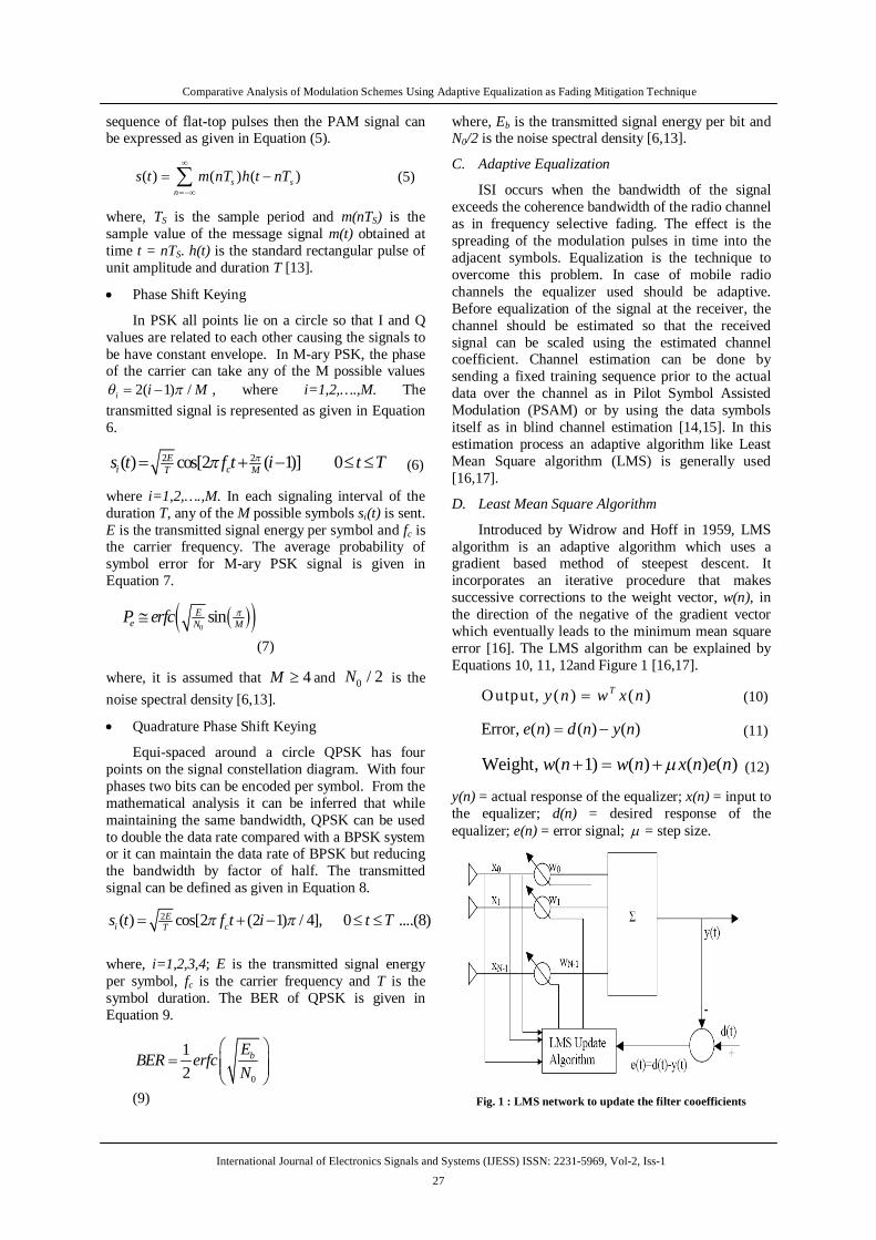
Introduced by Widrow and Hoff in 1959, LMS algorithm is an adaptive algorithm which uses a gradient based method of steepest descent. It incorporates an iterative procedure that makes successive corrections to the weight vector, w(n), in the direction of the negative of the gradient vector which eventually leads to the minimum mean square error [16]. The LMS algorithm can be explained by Equations 10, 11, 12and Figure 1 [16,17].
Output, ( ) ( )Ty n w x n (10)
Error, ( ) ( ) ( )e n d n y n (11)
Weight, ( 1) ( ) ( ) ( )w n w n x n e n (12)
y(n) = actual response of the equalizer; x(n) = input to the equalizer; d(n) = desired response of the equalizer; e(n) = error signal; = step size.
Fig. 1 : LMS network to update the filter cooefficients
International Journal of Electronics Signals and Systems (IJESS) ISSN: 2231-5969, Vol-2, Iss-1

Comparative Analysis of Modulation Schemes Using Adaptive Equalization as Fading Mitigation Technique
28
TABLE I. SYSTEM SPECIFICATION
Parameters Value M-ary level 256 SNR 35dB Phase Noise (frequency offset=200Hz)
-66dBc/Hz
Doppler Spectrum type for Rayleigh Fading Channel
Jakes
Discrete path delay vector [0 2e-6] Average path gain vectors [0 -3] K-factor 1 Numbe of taps 2 Number of samples per symbol 1 Leekage factor 1
IV. SYSTEM MODEL AND SPECIFICATION In this work, the software platform used is MATLAB and SIMULINK. The input to the model comes from a Random Integer Generator. The output of this block is fed to the Rectangular QAM Modulator Baseband block, where the modulation takes place. This modulated signal is passed through Multipath Rayleigh/Rician Fading Channel Block. To this faded signal both AWGN and phase noise is added through AWGN and Phase noise blocks. Phase noise is the frequency domain representation of the rapid, short-term, random fluctuations in the phase of a waveform caused by the time domain instabilities (jitter). This instability occurs due to the non-ideal behavior of oscillators. At the receiver this impaired signal is equalized using LMS Linear Equalizer Block. Finally, using the Rectangular QAM Demodulator Baseband Block the signal is demodulated. The symbol error rate is calculated using the Error Rate Calculation block. The final block diagrams are given in Figure 5 and 6, for Rayleigh and Rician channel, respectively. For Performance comparison, we have used the same Rayleigh fading model and inter-changed the modulation schemes with 256-QAM. Important system specifications are given Table 1.
V. SIMULATION RESULTS AND DISCUSSIONS
A. Effects of AWGN and Phase noise without Fading
Initially, a Simulink model is implemented where the effect of AWGN and phase noise is considered. 256-QAM is chosen as the modulation scheme. The signal constellation diagram of 256-QAM is shown in Figure 2. After demodulation of the signal at the receiver, BER is 0.0092.
Fig. 2 : 256-QAM constellation diagram
B. Effects of Fading in Addition to Noise
Now, the effect of fading channels in the presence of noise is considered. The Doppler shift is considered to be very less i.e. almost a flat fading channel. The SER after the introduction of the Rayleigh fading channel goes as high as 0.9848. In case of Rician fading channel the SER is almost 1. Hence, it can be concluded that due to the fading effect almost all the bits are erroneous. Therefore, suitable mitigation technique is required at the receiver. The Simulink models for Rayleigh and Rician fading are given in Figures 3 and 4, respectively.
C. Post Equalization
The final model in which we implemented adaptive equalizer is given in Figures 5 and 6 for Rayleigh and Rician fading channels, respectively. In the current implementation the filter weights are updated once for each symbol.
The desired input is used for training the equalizer which expects complex constellation points. The leekage factor 1 corresponds to the conventional weight update algorithm. We observe that after the received signal is equalized using this adaptive equalizer the SER drops to 0.036 and 0.0248 for Rayleigh and Rician fading channels, respectively. The signal constellation diagrams of 256-QAM before and after equalization is given in Figures 7 and 8 for Rayleigh and Rician fading channels, respectively.
Fig. 3 : Rayleigh Fading Model
International Journal of Electronics Signals and Systems (IJESS) ISSN: 2231-5969, Vol-2, Iss-1

Comparative Analysis of Modulation Schemes Using Adaptive Equalization as Fading Mitigation Technique
29
Fig. 4 : Rician Fading Model
Fig. 5: Adaptive Equalizer model for Rayleigh fading channel
Fig. 6 : Adaptive Equalizer model for Rician fading channel
Fig. 7 : (left) Before and (right) After Equalizer model for Rayleigh faching channel
Fig. 8 : (left) Before and (right) After Equalizer model for Rician faching channel
Moreover, it is observed that, although an equalizer is used, the SER is very high at low SNR. This implies that SNR should be wisely chosen. It should not be very low, and at the same time it cannot be very high due to the power constraints. Figure 9 for Rayleigh and Rician fading channels illustrate this point.
Fig. 9: SER vs SNR for (left) Rayleigh and (right) Rician fading channels
D. Performance Comparison of Modulation Schemes
We know that there are various digital modulation schemes that can be used for the transmission of data in wireless communication like QPSK, GMSK, PAM, PSK, FSK, QAM, etc. [6,7,8-12].
Adhering to some of the performance criteria like signaling speed, complexity of hardware, spectral efficiency etc, a comparative analysis of some modulation techniques (256-QAM, QPSK, 256-PAM and 256-PSK) is done to justify the decision of selecting 256-QAM. The comparison is based on Rayleigh fading channel, same equalizer model implemented for 256-QAM, and SNR=35dB.
When 256-PAM is used instead of 256-QAM, SER becomes 0.4718. The signal constellation diagrams of 256-PAM before and after equalization are given in Figure 10.
International Journal of Electronics Signals and Systems (IJESS) ISSN: 2231-5969, Vol-2, Iss-1

Comparative Analysis of Modulation Schemes Using Adaptive Equalization as Fading Mitigation Technique
30
Fig. 10 : Signal constellation diagram of 256-PAM (left) before
and (right) after equalization.
Using QPSK as the modulation technique for transmitting the data, the SER at the receiver goes to the minimum value of 0.0004. The Signal constellation diagram before and after equalization are given in Figure 11.
Fig.11: Signal constellation diagram of QPSK (left) before and (right) after equalization
Fig. 12 : Signal constellation of 256-PSK (left) before and
(right) after equalization
The value of M is chosen as 256. Using this scheme the SER becomes very high giving a value of 0.6464. The signal constellation diagrams before and after equalization are given in Figure 12.
From Table 2 we see that the performance of PSK is worst since 256-PSK is taken and therefore symbols lie very close to each other in the signal space diagram. Therefore, M less than 256 would be a better choice. PAM’s performance is also poor. Although, QPSK gives the best result in terms of SER, 256-QAM is chosen because of its spectral efficiency and comparable SER. The simulation results are in good agreement with the theory.
The plot given in Figure 13 illustrates the effect of SNR on symbol error probability for all the modulation schemes we have chosen. From the graph, it can be seen that QPSK gives the best performance. As SNR increases, 256-QAM’s performance is also comparable to QPSK. The advantage it gives is high bandwidth efficiency because each symbol consists of 8 bits. This spectral efficiency is nowadays the primary requirement of wireless communication. 256-PSK and 256-PAM does not perform satisfactorily even at higher levels of SNR.
TABLE II. SYMBOL ERROR RATES FOR VARIOUS MODULATION SCHEMES
Modulation Scheme SER at 35dB SNR 256-PAM 0.5688
QPSK 0.0004 256-PSK 0.6568 256-QAM 0.036
Fig. 13 : SER Comparison
VI. CONCLUSION
In this paper, using the same adaptive equalization technique and Rayleigh fading condition at an SNR of around 35dB, comparative performance analysis of some modulation techniques is performed. Results show that QPSK gives minimum SER. Although, QAM’s SER is little higher than QPSK, considering its spectral efficiency it is the best scheme to choose. Here, even after using M=256 (in M-QAM) the proposed equalizer performs fairly good to lower the SER to the accepted limits of wireless communication system. Thus, we justify our decision of selecting 256-QAM as the modulation scheme for data transmission.
International Journal of Electronics Signals and Systems (IJESS) ISSN: 2231-5969, Vol-2, Iss-1

Comparative Analysis of Modulation Schemes Using Adaptive Equalization as Fading Mitigation Technique
31
REFERENCES
[1] M. Rumney, "IMT-Advanced: 4G Wireless Takes Shape in an Olympic Year", Agilent Measurement Journal, September 2008.
[2] S. Ortiz Jr., “4G wireless begins to take shape,” Computer, vol. 40, no. 11, pp. 18–21, 2007.
[3] B. Sklar, "Rayleigh fading channels in mobile digital communication systems. I. Characterization," Communications Magazine, IEEE, vol. 35, pp. 90-100, 1997.
[4] T. S. Rappaport, Wireless communications: principles and practice vol. 207: Prentice Hall PTR New Jersey, 1996.
[5] B. Sklar, "Rayleigh fading channels in mobile digital communication systems. II. Mitigation," Communications Magazine, IEEE, vol. 35, pp. 90-100, 1997.
[6] V. Chauhan, M. Arora and R. S. Chauhan, “Comparative BER Performance of PSK based modulation Techniques under Multipath Fading” Adv. Appl. Sci. Res., 2011, 2 (4):521-527.
[7] Md. E. Haque, Md. G. Rashed and M. H. Kabir, “A Comprehensive Study and Performance Comparison of m-ary Modulation Schemes for an Efficient Wireless Mobile Communication System” International Journal of Computer Science, Engineering and Applications (IJCSEA) vol.1, no.3, June 2011.
[8] G. A. Mahdiraji and E. Zahedi, “Comparison of Selected Digital Modulation Schemes (OOK, PPM and DPIM) for Wireless Optical Communications” 4th Student Conference on Research and Development (SCOReD2006), Shah Alam, Selangor, Malaysia, 27-28 June, 2006.
[9] H.X. Wang, Y.B. Zhu, and T.Y. Zhang, "Performance Study of Modulation for Optical Wireless Communication", Laser & Optoelectronics Progress, vol.43, no.6, June 2006.
[10] G. Carron, R. Ness, L. Deneire, L. Van der Perre and M. Engels, “Comparison of Two Modulation Techniques Using Frequency Domain Processing for In-House” IEEE Transactions on Consumer Electronics, vol. 47, no. 1, February 2001.
[11] Z.Y. Pang, D.Z. Piao and C.Y. Zou, "Performance Comparisons of Several Modulation Schemes for Optical Wireless Communication", Journal of Guilin Institute of Electronic Technology, vol.22, no.5, pp.1-4, October 2002.
[12] B. Hashem and M. S. El-Hennawey, “Performance of the π/4-DQPSK, GMSK, and QAM Modulation Schemes in Mobile Radiowith Multipath Fading and Nonlinearities” IEEE Transactions on Vehicular Technology, vol.46, no. 2, May 1997.
[13] S. Haykin, Communication systems: Wiley-India, 2008.
[14] V. Prapulla, A. Mitra, R. Bhattacharjee and S. Nandi, “A Simplified Adaptive Decision Feedback Equalization Technique for π/4-DQPSK Signals” World Academy of Science, Engineering and Technology, 2008.
[15] M. S. Radenkovic, T. Bose, and B. Ramkumar, “Blind Adaptive Equalization of MIMO Systems: New Recursive Algorithms and Convergence Analysis”, IEEE Transactions on Circuits and Systems—I: Regular Papers, vol. 57, no. 7, July 2010.
[16] G. Malik and A. S. Sappal, “Adaptive Equalization Algorithms: An Overview”, (IJACSA) International Journal of Advanced Computer Science and Applications, vol. 2, no.3, March 2011.
[17] B. Widrow and M. E. Hoff, "Adaptive switching circuits," pp. 96-104, 1960.
[18] J. Bhalani, T.I. Trivedi and Y.P. Kosta, “Performance comparison of non-linear and adaptive equilization algorithms for wireless digital communication”, First Asian Himalayas International Conference on Internet, 2009.
International Journal of Electronics Signals and Systems (IJESS) ISSN: 2231-5969, Vol-2, Iss-1