comparative performance & simulation study of single...
TRANSCRIPT

International Journal of Current Engineering and Technology E-ISSN 2277 – 4106, P-ISSN 2347 – 5161 ©2015INPRESSCO®, All Rights Reserved Available at http://inpressco.com/category/ijcet
Research Article
2308| International Journal of Current Engineering and Technology, Vol.5, No.4 (Aug 2015)
Comparative Performance & Simulation Study of Single Phase Induction Motor using Multilevel Inverter
Shivpal Verma†*, Ankita Pande‡ and Hardik Daveϯ
†Electrical Engineering, RTMNU, D.B.A.C.E.R Nagpur India ‡Electrical Engineering RTMNU, R.G.C.E.R Nagpur India ϯMechanical Engineering, RTMNU, S.R.P.C.E Nagpur India
Accepted 30 June 2015, Available online 02 July 2015, Vol.5, No.4 (Aug 2015)
Abstract
This paper deals with the analysis of induction motor supplied by multilevel inverter (MLI). Generally, the poor quality of voltage and current of a conventional inverter fed induction motor is obtained due to the presence of harmonics and hence there is a significant level of energy losses. These losses can be reduced using multilevel inverter. In inverters by increasing the number of steps it generates the very high quality of the output voltage and current. By increasing the number of steps in output voltage, harmonics is reduces and significant level of energy losses is also reduced. A constant frequency multicarrier phase disposition PWM technique is implemented for the Cascaded MLI. Phase Disposition Sinusoidal Pulse Width Modulation (SPWM) technique is used for controlling frequency and voltage of MLI. The simulation is carried out using MATLAB/SIMULINK.
Keyword: SPWM, MLI, Induction motor, Total Harmonics Distortion (THD).
1. Introduction
1 All DC motors have been used during the last century in industries for variable speed applications, because its flux and torque can be controlled easily by means of changing the field and armature currents respectively. Furthermore, operation in the four quadrants of the torque speed plane including temporary standstill was achieved. Almost for a century, induction motor has been the workhorse of industry due to its robustness, low cost high efficiency and less maintenance. The induction motors were mainly used for essentially constant speed applications because of the unavailability of the variable- frequency voltage supply. The advancement of power electronics has made it possible to vary the frequency of the voltage supplies relatively easy, thus extending the use of the induction motor in variable speed drive applications. But due to the inherent coupling of flux and torque components in induction motor, it could not provide the torque performance as good as the DC motor (B. Biswas et al, 2009). In recent years, industry has begun to demand higher power equipment, which now reaches as the megawatt level. Controlled Ac drives in the megawatt range are usually connected to the medium voltage grids (2.3, 3.3, 4.16, or 6.9kv). For these reasons, a new family of multilevel inverters as emerged as the solution for working with higher voltage levels (B.
*Corresponding author: Shivpal Verma
Biswas et al, 2009). In a medium voltage and high power applications two level inverter have some limitations in operating at high frequency mainly due to switching loses and constraints of devices voltage\ power ratings (Alessandro Luiz et al, 2012) For a medium voltage grid it is troublesome to connect only one power semiconductor switches directly. As a result, multilevel power converter structure has been introduced as an alternative in high power and medium voltage situations (K.Srinivas et al, 2012). The most attractive features of multilevel inverters are as follows. They can generate output voltage with extremely low distortion (K.Srinivas et al, 2012). They draw input current with very low distortion. The multi level inverters are mainly classified as Diode clamped, Flying capacitor inverter and cascaded multi level inverter. The cascaded multilevel control method is very easy when compare to other multilevel inverter because it doesn’t require any clamping diode and flying capacitor (K.Srinivas et al, 2012). 2. Cascaded Multilevel Inverter Topology
A cascaded multilevel inverter made up of series connected single full H-bridge inverter, each with their own isolated dc bus. This multilevel inverter can generate almost sinusoidal waveform voltage from several separate dc sources, which may be obtained from solar cells, fuel cells, batteries, etc. This type of converter does not need any transformer or clamping diodes or flying capacitors. Each level can generate
Ankita Pande et al Comparative Analysis of Different SPWM Techniques for Modular Multilevel Inverter
2309| International Journal of Current Engineering and Technology, Vol.5, No.4 (Aug 2015)
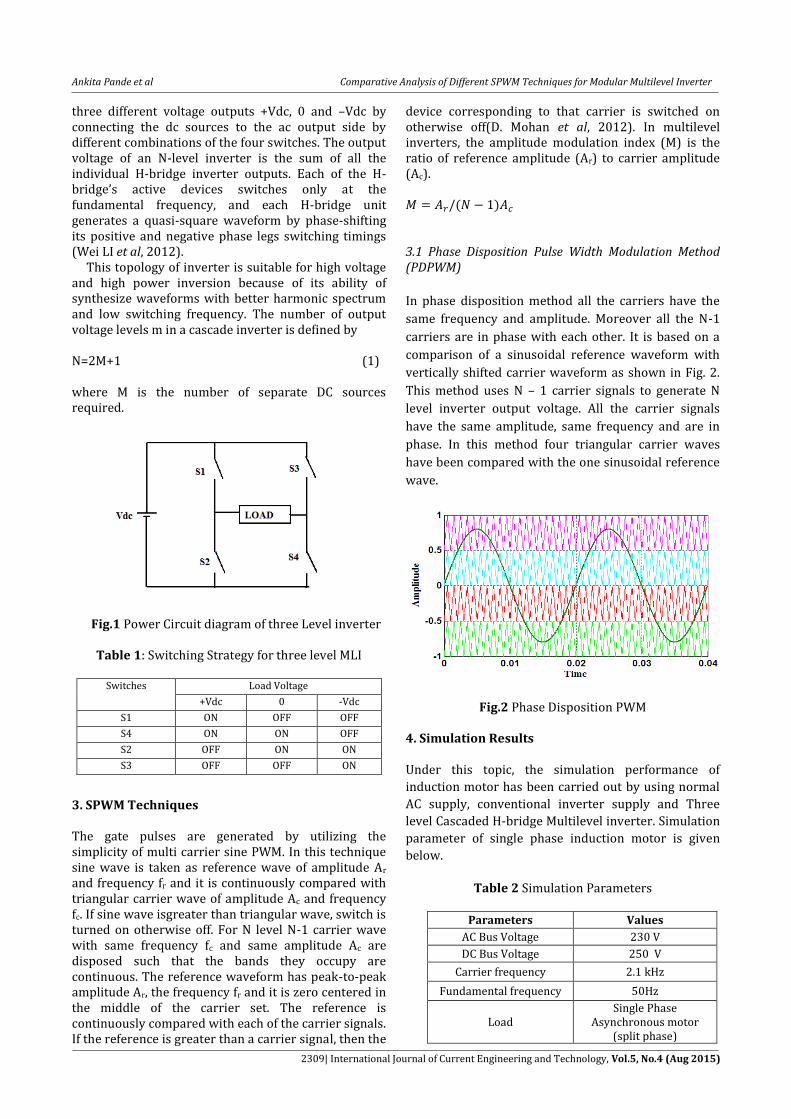
three different voltage outputs +Vdc, 0 and –Vdc by connecting the dc sources to the ac output side by different combinations of the four switches. The output voltage of an N-level inverter is the sum of all the individual H-bridge inverter outputs. Each of the H-bridge’s active devices switches only at the fundamental frequency, and each H-bridge unit generates a quasi-square waveform by phase-shifting its positive and negative phase legs switching timings (Wei LI et al, 2012). This topology of inverter is suitable for high voltage and high power inversion because of its ability of synthesize waveforms with better harmonic spectrum and low switching frequency. The number of output voltage levels m in a cascade inverter is defined by N=2M+1 (1) where M is the number of separate DC sources required.
Fig.1 Power Circuit diagram of three Level inverter
Table 1: Switching Strategy for three level MLI
3. SPWM Techniques The gate pulses are generated by utilizing the simplicity of multi carrier sine PWM. In this technique sine wave is taken as reference wave of amplitude Ar and frequency fr and it is continuously compared with triangular carrier wave of amplitude Ac and frequency fc. If sine wave isgreater than triangular wave, switch is turned on otherwise off. For N level N-1 carrier wave with same frequency fc and same amplitude Ac are disposed such that the bands they occupy are continuous. The reference waveform has peak-to-peak amplitude Ar, the frequency fr and it is zero centered in the middle of the carrier set. The reference is continuously compared with each of the carrier signals. If the reference is greater than a carrier signal, then the
device corresponding to that carrier is switched on otherwise off(D. Mohan et al, 2012). In multilevel inverters, the amplitude modulation index (M) is the ratio of reference amplitude (Ar) to carrier amplitude (Ac).
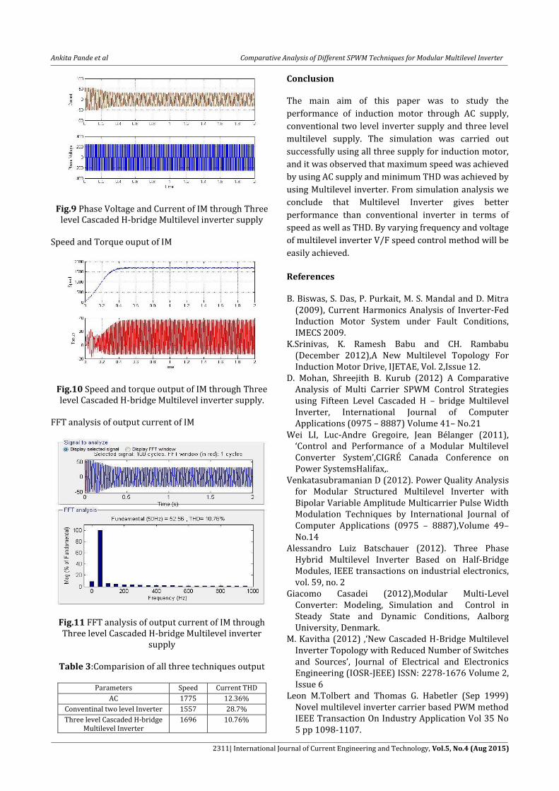
3.1 Phase Disposition Pulse Width Modulation Method (PDPWM)
In phase disposition method all the carriers have the
same frequency and amplitude. Moreover all the N-1
carriers are in phase with each other. It is based on a
comparison of a sinusoidal reference waveform with
vertically shifted carrier waveform as shown in Fig. 2.
This method uses N – 1 carrier signals to generate N
level inverter output voltage. All the carrier signals
have the same amplitude, same frequency and are in
phase. In this method four triangular carrier waves
have been compared with the one sinusoidal reference
wave.
Fig.2 Phase Disposition PWM
4. Simulation Results Under this topic, the simulation performance of
induction motor has been carried out by using normal
AC supply, conventional inverter supply and Three
level Cascaded H-bridge Multilevel inverter. Simulation
parameter of single phase induction motor is given
below.
Table 2 Simulation Parameters
Parameters Values
AC Bus Voltage 230 V
DC Bus Voltage 250 V
Carrier frequency 2.1 kHz
Fundamental frequency 50Hz
Load Single Phase
Asynchronous motor (split phase)
Switches Load Voltage
+Vdc 0 -Vdc
S1 ON OFF OFF
S4 ON ON OFF
S2 OFF ON ON
S3 OFF OFF ON

Ankita Pande et al Comparative Analysis of Different SPWM Techniques for Modular Multilevel Inverter
2310| International Journal of Current Engineering and Technology, Vol.5, No.4 (Aug 2015)
4.1 Simulation performance of induction motor through AC supply Output Voltage and Current of motor is given below
Fig.3 Phase Voltage and Current of IM through AC supply
Speed and Torque ouput of IM
Fig.4 Speed and torque output of IM through AC supply
FFT analysis of output current of IM
Fig.5 FFT analysis of output current of IM through AC supply
4.2 Simulation performance of induction motor through Conventional two level inverter supply Output Voltage and Current of motor is given below.
Fig.6: Phase Voltage and Current of IM through Conventional two level inverter supply
Speed and Torque ouput of IM
Fig.7 Speed and torque output of IM through Conventional two level inverter supply
FFT analysis of output current of IM
Fig.8 FFT analysis of output current of IM through Converntional two level inverter supply
4.3 Simulation performance of induction motor through three level Cascaded H-Bridge Multilevel Inverter two level inverter supply Output Voltage and Current of motor is given below.
Ankita Pande et al Comparative Analysis of Different SPWM Techniques for Modular Multilevel Inverter
2311| International Journal of Current Engineering and Technology, Vol.5, No.4 (Aug 2015)
Fig.9 Phase Voltage and Current of IM through Three level Cascaded H-bridge Multilevel inverter supply
Speed and Torque ouput of IM
Fig.10 Speed and torque output of IM through Three level Cascaded H-bridge Multilevel inverter supply.
FFT analysis of output current of IM
Fig.11 FFT analysis of output current of IM through Three level Cascaded H-bridge Multilevel inverter
supply
Table 3:Comparision of all three techniques output
Parameters Speed Current THD
AC 1775 12.36%
Conventinal two level Inverter 1557 28.7%
Three level Cascaded H-bridge Multilevel Inverter
1696 10.76%
Conclusion The main aim of this paper was to study the
performance of induction motor through AC supply,
conventional two level inverter supply and three level
multilevel supply. The simulation was carried out
successfully using all three supply for induction motor,
and it was observed that maximum speed was achieved
by using AC supply and minimum THD was achieved by
using Multilevel inverter. From simulation analysis we
conclude that Multilevel Inverter gives better
performance than conventional inverter in terms of
speed as well as THD. By varying frequency and voltage
of multilevel inverter V/F speed control method will be
easily achieved.
References B. Biswas, S. Das, P. Purkait, M. S. Mandal and D. Mitra
(2009), Current Harmonics Analysis of Inverter-Fed Induction Motor System under Fault Conditions, IMECS 2009.
K.Srinivas, K. Ramesh Babu and CH. Rambabu (December 2012),A New Multilevel Topology For Induction Motor Drive, IJETAE, Vol. 2,Issue 12.
D. Mohan, Shreejith B. Kurub (2012) A Comparative Analysis of Multi Carrier SPWM Control Strategies using Fifteen Level Cascaded H – bridge Multilevel Inverter, International Journal of Computer Applications (0975 – 8887) Volume 41– No.21
Wei LI, Luc-Andre Gregoire, Jean Bélanger (2011), ‘Control and Performance of a Modular Multilevel Converter System’,CIGRÉ Canada Conference on Power SystemsHalifax,.
Venkatasubramanian D (2012). Power Quality Analysis for Modular Structured Multilevel Inverter with Bipolar Variable Amplitude Multicarrier Pulse Width Modulation Techniques by International Journal of Computer Applications (0975 – 8887),Volume 49– No.14
Alessandro Luiz Batschauer (2012). Three Phase Hybrid Multilevel Inverter Based on Half-Bridge Modules, IEEE transactions on industrial electronics, vol. 59, no. 2
Giacomo Casadei (2012),Modular Multi-Level Converter: Modeling, Simulation and Control in Steady State and Dynamic Conditions, Aalborg University, Denmark.
M. Kavitha (2012) ,‘New Cascaded H-Bridge Multilevel Inverter Topology with Reduced Number of Switches and Sources’, Journal of Electrical and Electronics Engineering (IOSR-JEEE) ISSN: 2278-1676 Volume 2, Issue 6
Leon M.Tolbert and Thomas G. Habetler (Sep 1999) Novel multilevel inverter carrier based PWM method IEEE Transaction On Industry Application Vol 35 No 5 pp 1098-1107.