comparative study of pid and fuzzy tuned pid …ijiet.com/wp-content/uploads/2013/09/39.pdf ·...
TRANSCRIPT
�
� � �
Comparative study of PID and Fuzzy tuned PID
controller for speed control of DC motor
Mohammed Shoeb Mohiuddin
Assistant Professor, Department of Electrical Engineering
Mewar University, Chittorgarh, Rajasthan, India
Abstract- In this paper we have designed a separately excited DC motor whose speed can be controlled using PID and
fuzzy tuned PID controller first, the fuzzy logic controller is designed according to fuzzy rules so that the systems are
fundamentally robust. There are 25 fuzzy rules for self-tuning of each parameter of PID controller. The FLC has two
inputs. One is the motor speed error second is change in speed error and the output of the FLC i.e. the parameters of PID
controller are used to control the speed of the separately excited DC Motor. The fuzzy self-tuning approach implemented
on a conventional PID structure was able to improve the dynamic as well as the static response of the system. Comparison
between the conventional output and the fuzzy self-tuning output was done on the basis of the simulation result obtained
by MATLAB. The simulation results demonstrate that the designed self-tuned PID controller realize a good dynamic
behavior of the DC motor, a perfect speed tracking with less rise and settling time, minimum overshoot, minimum steady
state error and give better performance compared to conventional PID controller.
Keywords – DC motor: Fuzzy tuned PID: Speed control
I. INTRODUCTION
The speed of DC motors can be adjusted within wide boundaries so that this provides easy controllability and high
performance. DC motors used in many applications such as still rolling mills, electric trains, electric vehicles,
electric cranes and robotic manipulators require speed controllers to perform their tasks. Speed controller of DC
motors is carried out by means of voltage control in 1981 firstly by Ward Leonard
The proportional – integral – derivative (PID) controller operates the majority of the control system in the world. It
has been reported that more than 95% of the controllers in the industrial process control applications are of PID type
as no other controller match the simplicity, clear functionality, applicability and ease of use offered by the PID
controller [3], [4]. PID controllers provide robust and reliable performance for most systems if the PID parameters
are tuned properly.
The major problems in applying a conventional control algorithm (PI, PD, PID) in a speed controller are the effects
of non-linearity in a DC motor. The nonlinear characteristics of a DC motor such as saturation and fiction could
degrade the performance of conventional controllers [1], [2].Generally, an accurate nonlinear model of an actual DC
motor is difficult to find and parameter obtained from systems identification may be only approximated values. The
field of Fuzzy control has been making rapid progress in recent years. Fuzzy logic control (FLC) is one of the most
successful applications of fuzzy set theory, introduced by L.A Zadeh in 1973 and applied (Mamdani 1974) in an
attempt to control system that are structurally difficult to model.
II. PROPOSED ALGORITHM
A. Motor model –
When a separately excited motor is excited by a field current of if and an armature current of ia flows in the circuit,
the motor develops a back emf and a torque to balance the load torque at a particular speed.
The if is independent of the ia .Each windings are supplied separately. Any change in the armature current has no
effect on the field current. The if is normally much less than the ia.
� � � � � � � � � � � � � � � � � � � � � � � � � � � � � � � � � � � � � � � � � � � � � � � � � � � � � � � � � � � � � �
� � � � � � � � � � � � � � � � � � � ! " � � � � # � � $ %
�����������������������������
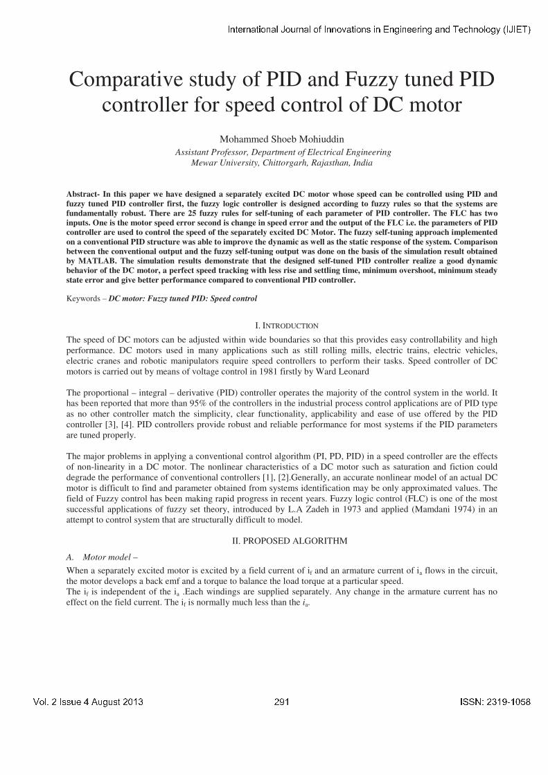
Figure1: Separately excited DC motor
Where
Va is the armature voltage. (In volt)
Eb is back emf the motor (In volt)
Ia is the armature current (In ampere)
Ra is the armature resistance (In ohm)
La is the armature inductance (In Henry)
Tm is the mechanical torque developed (In Nm)
Jm is moment of inertia (In kg/m²)
Bm is friction coefficient of the motor (In Nm/ (rad/sec))
� is angular velocity (In rad/sec)
The armature voltage equation is given by:
Va =Eb+ IaRa+ La (dIa/dt) -------------------(1)
Now the torque balance equation will be given by:
Tm = Jmd�/dt +Bm�+TL --------------------(2)
Where: TL is load torque in Nm.
Friction in rotor of motor is very small (can be neglected),so Bm=0
Therefore, new torque balance equation will be given by:
Tm = Jmd�/dt + TL ---------------------------(3)
Taking field flux as � and Back EMF Constant as K. Equation for back emf of motor will be:
Eb = K � � ------------------(4)
Also, Tm = K � Ia-------------------------------------(5)
Taking Laplace transform of the motor’s armature voltage equation we get
Ia(s) = (Va – K��)/ Ra (1+ LaS/Ra) ---------------(6) and
�(s) = (Tm - TL) /JS = (K�Ia - TL) /JmS ------------(7)
(Armature Time Constant) Ta= La/Ra
� � � � � � � � � � � � � � � � � � � � � � � � � � � � � � � � � � � � � � � � � � � � � � � � � � � � � � � � � � � � � �
� � � � � � � � � � � � � � � � � � � ! " � � � � # � � $ %

�����������������������������
Figure 2: Block Model of Separately Excited DC Motor
TABLE I. DC MOTOR PARAMETERS
Parameters Value
Armature resistance (Ra) 0.5�
Armature inductance (La) 0.02 H
Armature voltage (Va) 200 V
Mechanical inertia (jm) 0.1 Kg.m2
Friction coefficient (Bm) 0.008 N.m/rad/sec
Back emf constant (k) 1.25 V/rad/sec
Rated speed 1500r.p.m
III. FUZZY LOGIC CONTROLLER
The fuzzy logic foundation is based on the simulation of people’s opinions and perceptions to control any system.
One of the methods to simplify complex systems is to tolerate to imprecision, vagueness and uncertainty up to some
extent [10]. An expert operator develops flexible control mechanism using words like “suitable, not very suitable,
high, little high, much and far too much that are frequently used words in people’s life. Fuzzy logic control is
constructed on these logical relationships. Fuzzy sets are used to show linguistic variables. Fuzzy Sets Theory is first
introduced in 1965 by Zadeh to express and process fuzzy knowledge [11, 12]. There is a strong relationship
between fuzzy logic and fuzzy set theory that is similar relationship between Boolean logic and classic set theory.
Fig.3 shows a basic FLC structure.
Figure 3: Structure of fuzzy logic controller
The input to the Self-tuning Fuzzy PID Controller are speed error "e(t)" and Change-in-speed error "de(t)". The
input shown in figure are described by
� � � � � � � � � � � � � � � � � � � � � � � � � � � � � � � � � � � � � � � � � � � � � � � � � � � � � � � � � � � � � �
� � � � � � � � � � � � � � � � � � � ! " � � � � # � � $ %
�����������������������������
e (t)=wr(t)-wa(t)
de (t)=e(t)-e(t-1)
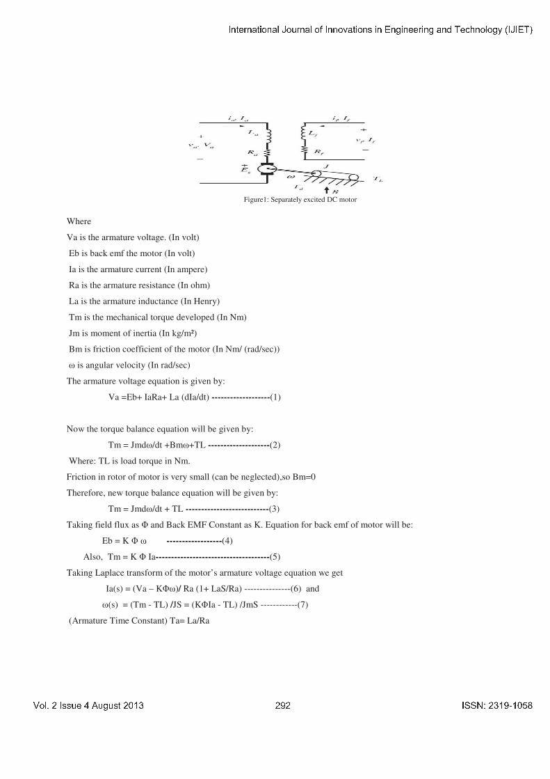
Using fuzzy control rules on-line, PID parameters “KP",” KI",” KD" are adjusted, which constitute a self-
tuning fuzzy PID controller as shown in Figure4.
Figure 4: The structure of self-tuning fuzzy PID controller
PID parameters fuzzy self-tuning is to find the fuzzy relationship between the three parameters of PID and "e" and
"de", and according to the principle of fuzzy control, to modify the three parameters in order to meet different
requirements for control parameters when "e" and "de" are different, and to make the control object a good dynamic
and static performance
In order to improve the performance of FLC, the rules and membership functions are adjusted. The membership
functions are adjusted by making the area of membership functions near ZE region narrower to produce finer control
resolution. On the other hand, making the area far from ZE region wider gives faster control response. Also the
performance can be improved by changing the severity of rules [14]. An experiment to study the effect of rise time
(Tr), maximum overshoot (Mp) and steady-state error (SSE) when varying KP, KI and KD was conducted. The
results of the experiment were used to develop 25-rules for the FLC of KP, KI and KD.
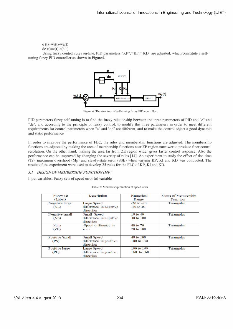
3.1 DESIGN OF MEMBERSHIP FUNCTION (MF)
Input variables: Fuzzy sets of speed error (e) variable
Table 2: Membership function of speed error
� � � � � � � � � � � � � � � � � � � � � � � � � � � � � � � � � � � � � � � � � � � � � � � � � � � � � � � � � � � � � �
� � � � � � � � � � � � � � � � � � � ! " � � � � # � � $ %
�����������������������������
Figure 5: Membership function for input variable “e”
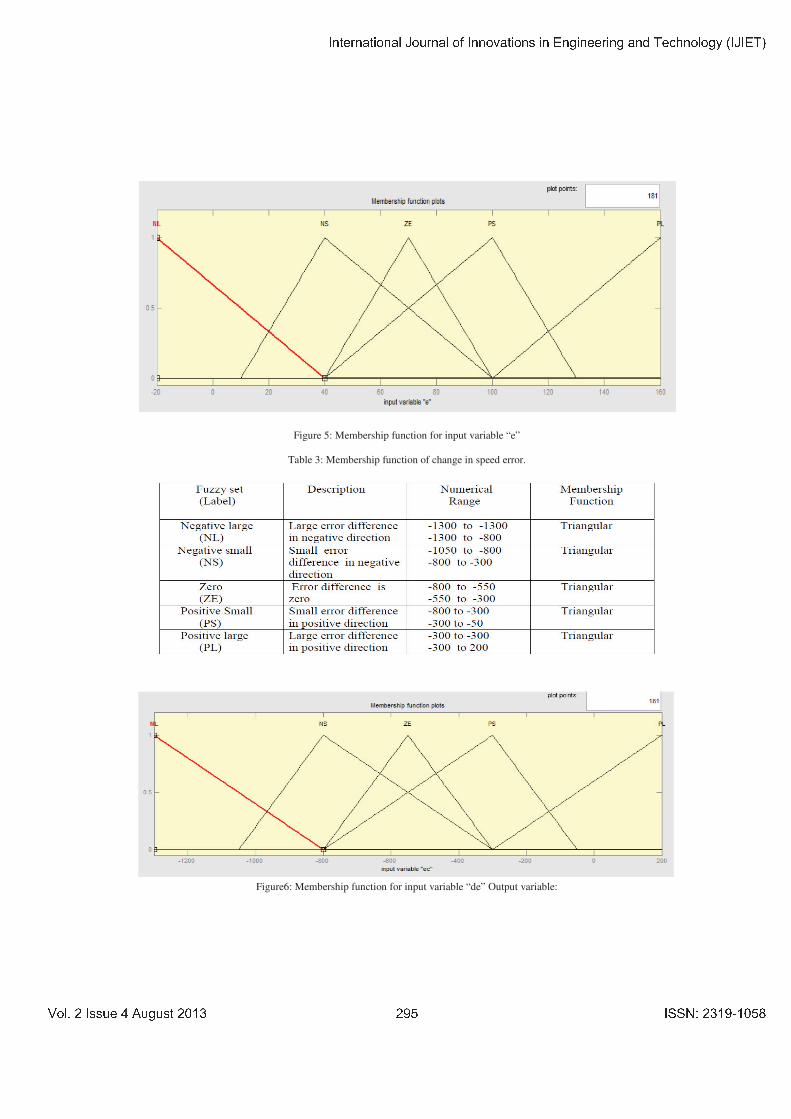
Table 3: Membership function of change in speed error.
Figure6: Membership function for input variable “de” Output variable:
� � � � � � � � � � � � � � � � � � � � � � � � � � � � � � � � � � � � � � � � � � � � � � � � � � � � � � � � � � � � � �
� � � � � � � � � � � � � � � � � $ � ! " � � � � # � � $ %
�����������������������������
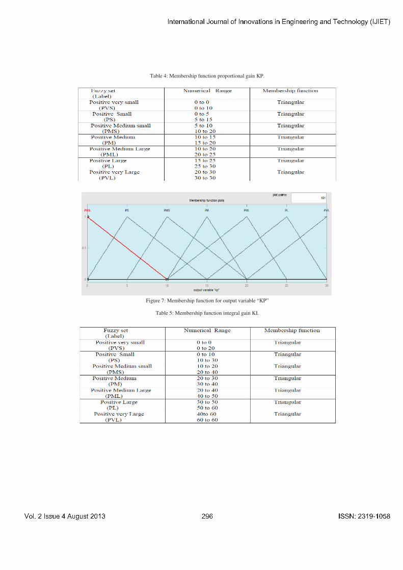
Table 4: Membership function proportional gain KP.
Figure 7: Membership function for output variable “KP”
Table 5: Membership function integral gain KI.
� � � � � � � � � � � � � � � � � � � � � � � � � � � � � � � � � � � � � � � � � � � � � � � � � � � � � � � � � � � � � �
� � � � � � � � � � � � � � � � � & � ! " � � � � # � � $ %
�����������������������������
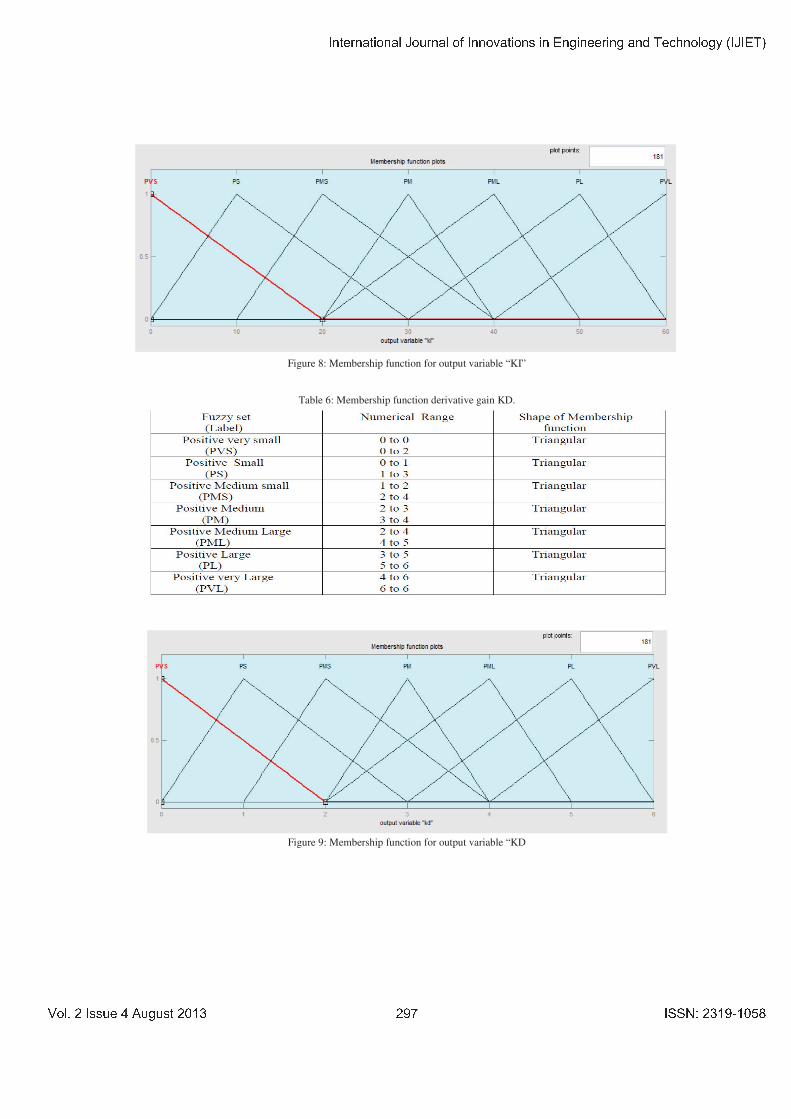
Figure 8: Membership function for output variable “KI”
Table 6: Membership function derivative gain KD.
Figure 9: Membership function for output variable “KD
� � � � � � � � � � � � � � � � � � � � � � � � � � � � � � � � � � � � � � � � � � � � � � � � � � � � � � � � � � � � � �
� � � � � � � � � � � � � � � � � ' � ! " � � � � # � � $ %

�����������������������������
3.2. DESIGN OF FUZZY RULES
Table 7: Fuzzy rule table for KP
Table 8: Fuzzy rule table for KI
Table 9: Fuzzy rule table for KD
� � � � � � � � � � � � � � � � � � � � � � � � � � � � � � � � � � � � � � � � � � � � � � � � � � � � � � � � � � � � � �
� � � � � � � � � � � � � � � � � % � ! " � � � � # � � $ %
�����������������������������
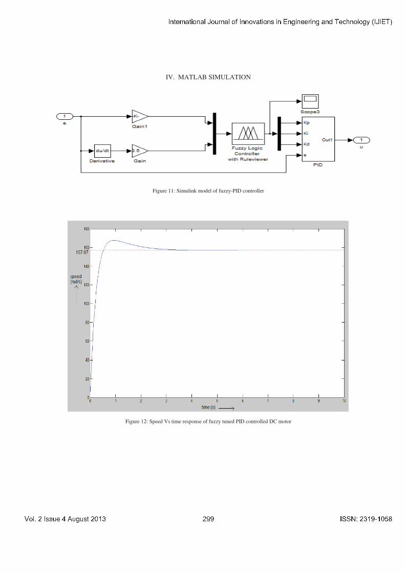
IV. MATLAB SIMULATION
Figure 11: Simulink model of fuzzy-PID controller
Figure 12: Speed Vs time response of fuzzy tuned PID controlled DC motor
� � � � � � � � � � � � � � � � � � � � � � � � � � � � � � � � � � � � � � � � � � � � � � � � � � � � � � � � � � � � � �
� � � � � � � � � � � � � � � � � � � ! " � � � � # � � $ %
�����������������������������
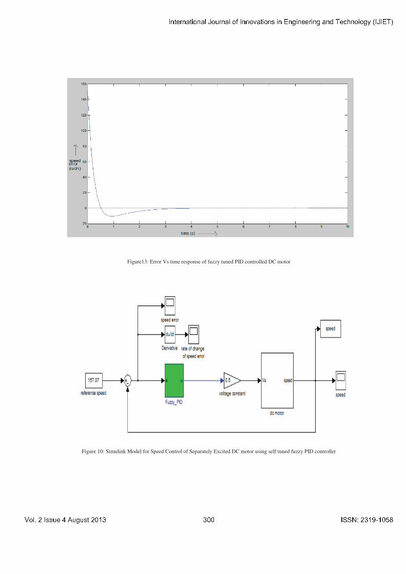
Figure13: Error Vs time response of fuzzy tuned PID controlled DC motor
Figure 10: Simulink Model for Speed Control of Separately Excited DC motor using self tuned fuzzy PID controller
� � � � � � � � � � � � � � � � � � � � � � � � � � � � � � � � � � � � � � � � � � � � � � � � � � � � � � � � � � � � � �
� � � � � � � � � � � � � � � � � � � ! " � � � � # � � $ %
�����������������������������
V. CONCLUSION
Comparison between self tuned fuzzy PID and conventional PID controller Self-tuned tuning PID controller is less
compared to conventional PID controller.
The three parameters "KP", "KI", "KD" of conventional PID control need to be constantly adjust adjusted online in
order to achieve better control performance. Fuzzy self-tuning PID parameters controller can automatically adjust
PID parameters in accordance with the speed error and the rate of speed error-change, so it has better self-adaptive
capacity fuzzy PID parameter controller has smaller overshoot and less rising and settling time than conventional
PID controller and has better dynamic response properties and steady-state properties. Steady state error in case of
self tuned fuzzy PID is less compared to conventional PID controller.
The fuzzy controller adjusted the proportional, integral and derivate (KP, KI, KD) gains of the PID controller
according to speed error and change in speed error .From the simulation results it is concluded that ,compared with
the conventional PID controller, self-tuning PID controller has a better performance in both transient and steady
state response. The self tuning FLC has better dynamic response curve, shorter response time, small overshoot,
small steady state error (SSE), high steady precision compared to the conventional PID controller.
REFERENCES
[1] B.J. Chalmers, “Influence of saturation in brushless permanent magnet drives.” IEE proc. B, Electr.Power Appl, vol.139, no.1, 1992.
[2] C.T. Johnson and R.D. Lorenz, “Experimental identification of friction and its compensation in precise, position controlled mechanism.”
IEEE Trans. Ind ,Applicat, vol.28, no.6, 1992.
[3] J. Zhang, N. Wang and S. Wang, “A developed method of tuning PID controllers with fuzzy rules for integrating process,” Proceedings of
the American Control Conference, Boston, 2004, pp. 1109-1114.
[4] K.H. Ang, G. Chong and Y. Li, “PID control system analysis, design and technology,” IEEE transaction on Control System Technology,
Vol.13, No.4, 2005, pp. 559-576
[5] H.X.Li and S.K.Tso, "Quantitative design and analysis of Fuzzy Proportional-Integral-Derivative Control- a Step towards Auto tuning",
International journal of system science, Vol.31, No.5, 2000, pp.545-553.
[6] Thana Pattaradej, Guanrong Chen and PitikhateSooraksa, "Design and Implementation of Fuzzy PID Control of a bicycle robot", Integrated
computer-aided engineering, Vol.9, No.4, 2002.
[7] Weiming Tang, Guanrong Chen and Rongde Lu, “A Modified Fuzzy PI Controller for a Flexible-joint Robot Arm with Uncertainties”,
Fuzzy Set and System, 118 (2001) 109-119.
[8] PavolFedor, Daniela Perduková, “A Simple Fuzzy Controller Structure,”ActaElectrotechnica ET Informatica No. 4, Vol. 5, 2005
[9] Maher M.F. Algreer andYhyaR.M.Kuraz, “Design Fuzzy Self Tuning of PID Controller for Chopper-Fed DC Motor drive.” Kuraz
[10] J.Klir. George, Yuan, Bo. “Furry Sets and Fuzzy Logic- Theory and Applications”
[11] L. A. Zadeh, ‘‘Fuzzy Sets“Informal Control, vol.8, pp 338- 353, 1965
[12] L. A. Zadeh, ‘Outline of a new approach to the analysis Complex systems and decision processes” IEEE Trans. Syst. Man Cybem, vol.
SMC-3, pp. 2844, I973
[13] Y. Tipsuwan, Y. Chow, “Fuzzy Logic Micmcontroller Implementation for DC Motor Speed Control”. IEEE. 1999
[14] M.Chow and A. Menozzi ,”on the comparison of emerging and conventional techniques for DC motor control” proc.IECON ,PP.1008-
1013, 1992.
[15] Ogata, K., Modern Control Engineering. Englewood Cliffs, NJ: Prentice Hall, 2001
[16] P.S Bhimbhra, electrical machinery, New Delhi, Khanna Publishers.
� � � � � � � � � � � � � � � � � � � � � � � � � � � � � � � � � � � � � � � � � � � � � � � � � � � � � � � � � � � � � �
� � � � � � � � � � � � � � � � � � � ! " � � � � # � � $ %