comparators (1)
TRANSCRIPT
1
Metrology
Mr. Amit Pancharya MNIT Jaipur
Inspection by Measurement
Direct Measurement
◦ Vernier Caliper, Vernier Height gauge, Verneir Depth gauge
◦Outside Micrometer, Inside Micrometer, Depth Micrometer,
◦ Slip gauges (gauge blocks), length
bars,etc.
Indirect Measurement
◦ Comparators
2
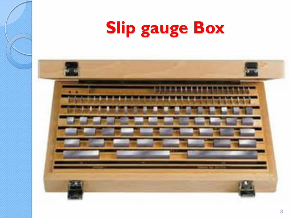
Slip gauge Box
3
Comparators
Comparing the manufactured part to the master part envisaged by the designer
Dimensional variation from the master part can be amplified and measured so as to get the deviation and the instruments for doing that are called comparators
◦ Mechanical Comparators
◦ Optical Comparators
◦ Pneumatic Comparators
4
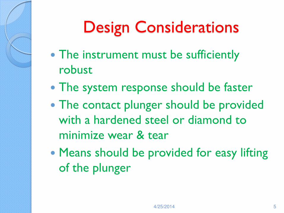
Design Considerations
The instrument must be sufficiently robust
The system response should be faster
The contact plunger should be provided with a hardened steel or diamond to minimize wear & tear
Means should be provided for easy lifting of the plunger
4/25/2014 5
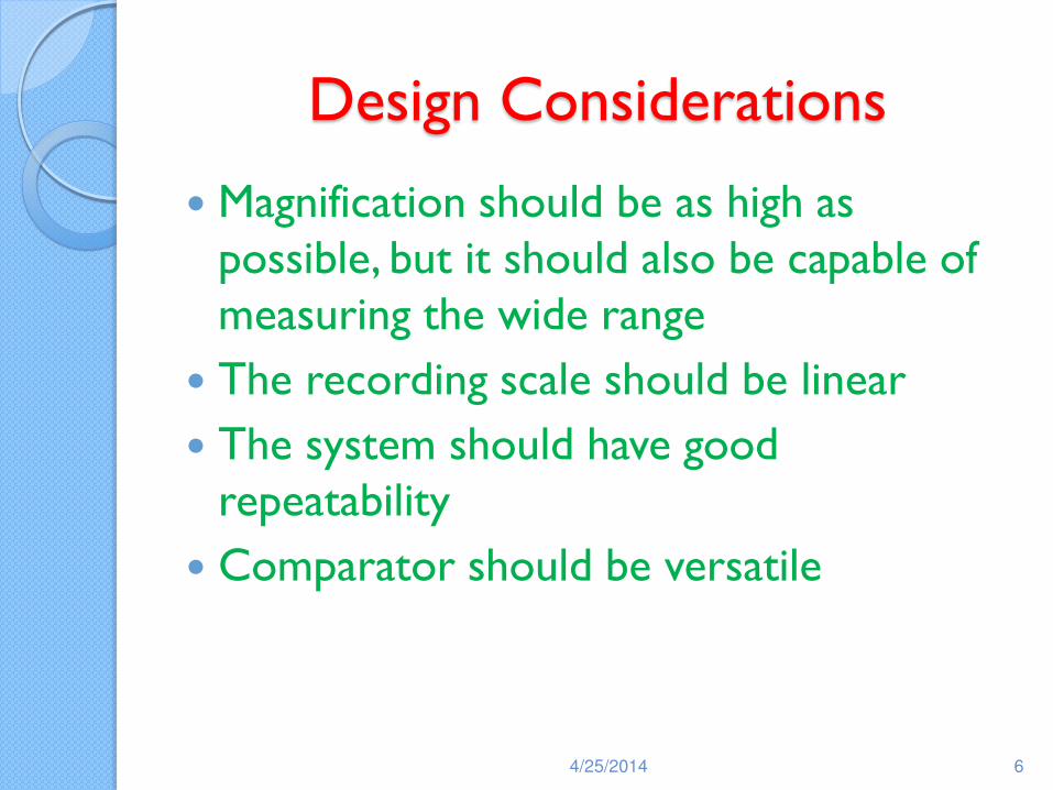
Design Considerations
Magnification should be as high as possible, but it should also be capable of measuring the wide range
The recording scale should be linear
The system should have good repeatability
Comparator should be versatile
4/25/2014 6
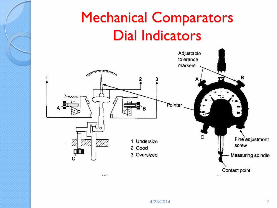
Mechanical Comparators Dial Indicators
4/25/2014 7
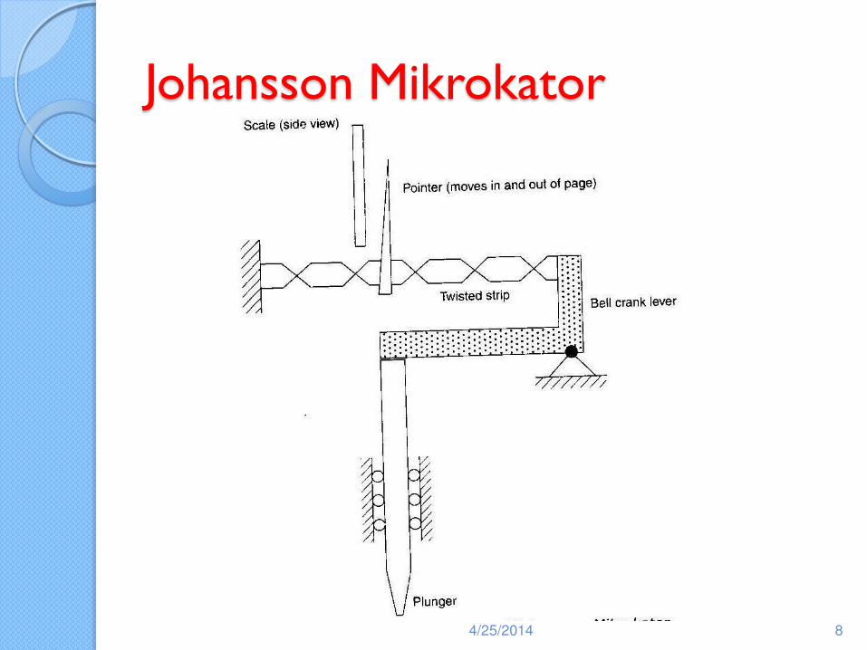
Johansson Mikrokator
4/25/2014 8
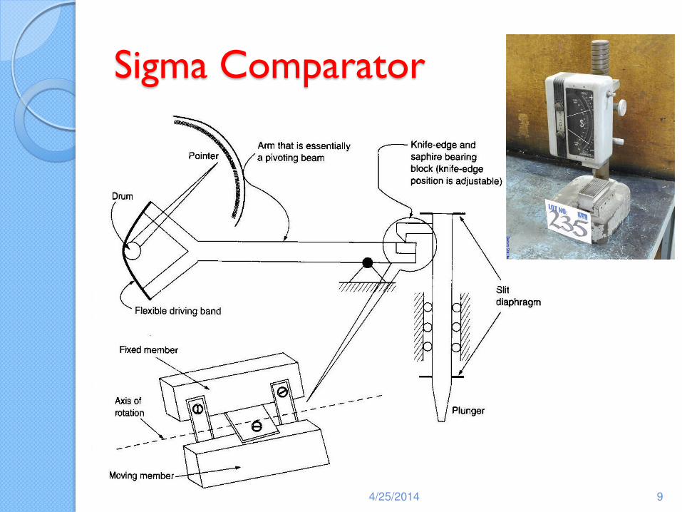
Sigma Comparator
4/25/2014 9
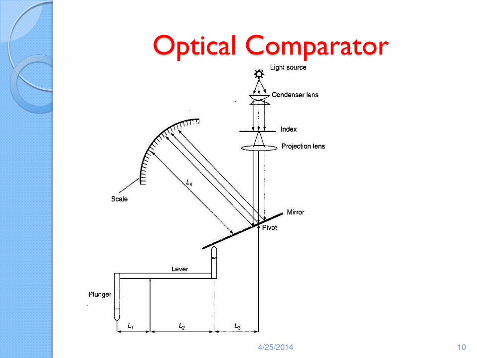
Optical Comparator
4/25/2014 10
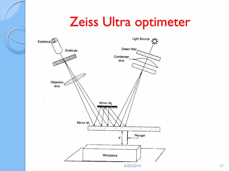
Zeiss Ultra optimeter
4/25/2014 11
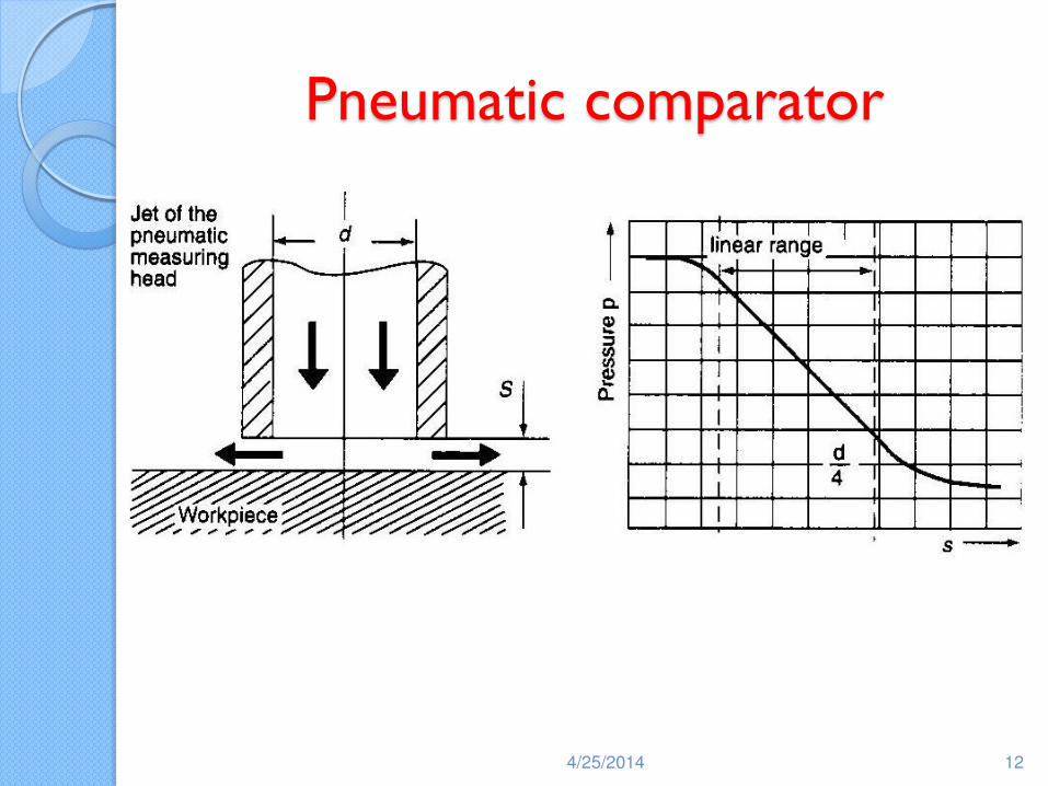
Pneumatic comparator
4/25/2014 12
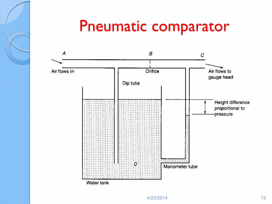
Pneumatic comparator
4/25/2014 13
Angular Measurements
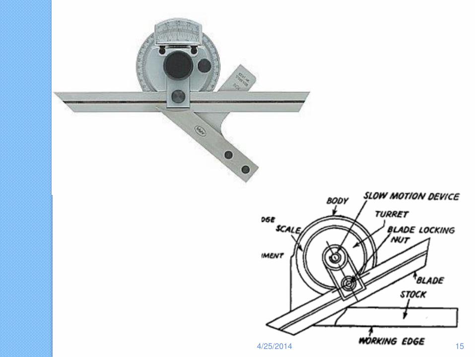
Angle Measuring Devices: Bevel Protractors & Angle Gauges measure the angle between the surfaces of a part or assembly
Bevel Protractor: It normally can read about 5 minutes of a degree. It consists of a sliding blade which can be set at some with respect to the stock. The reading can be obtained with the help of main scale and Vernier scale.
4/25/2014 14
4/25/2014 15
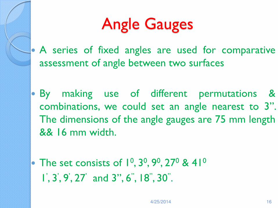
Angle Gauges
A series of fixed angles are used for comparative assessment of angle between two surfaces
By making use of different permutations & combinations, we could set an angle nearest to 3”. The dimensions of the angle gauges are 75 mm length && 16 mm width.
The set consists of 10, 30, 90, 270 & 410
1’, 3’, 9’, 27’ and 3”, 6”, 18”, 30”.
4/25/2014 16
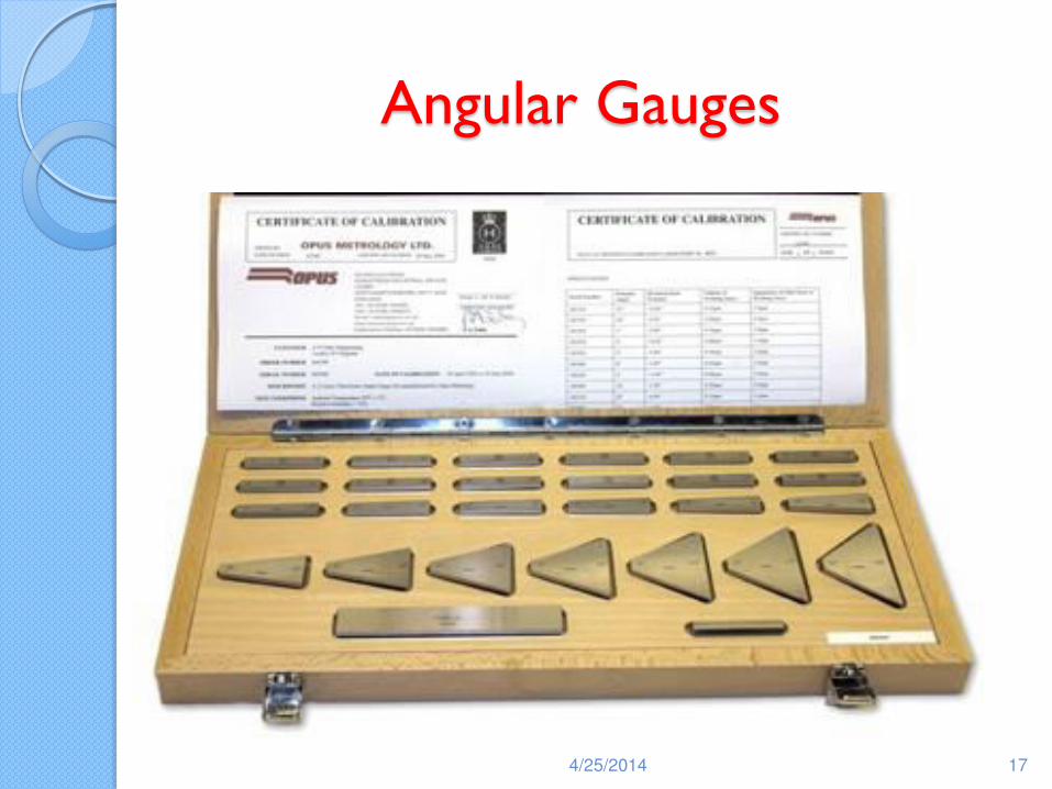
Angular Gauges
4/25/2014 17
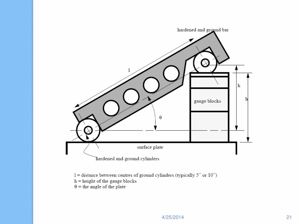
Sine Bar
A sine bar is a high precision angle measuring instrument. It is used in conjunction with other accessories such as slip gauges, angle gauges, etc.
It consists of a bar carrying two rollers set at a known centre distance. The options are 100 mm, 250 mm, etc.
They are available in several designs.
4/25/2014 18
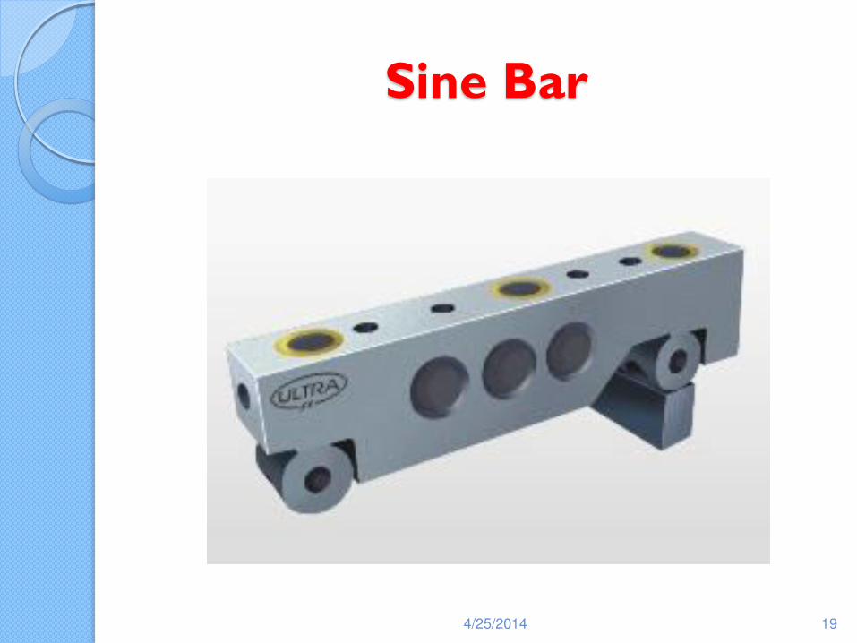
Sine Bar
4/25/2014 19
Sine Bar Contd..
Design Requirements are:
◦ The rollers must be of equal diameters and true geometric cylinders
◦ The distance between the roller axes must be precisely known and it should be same
◦ The upper surface of the bar must be flat , parallel with the roller axes and equidistant from each other
◦ The accuracy of the sine Bar depends on the above factors.
4/25/2014 20
4/25/2014 21
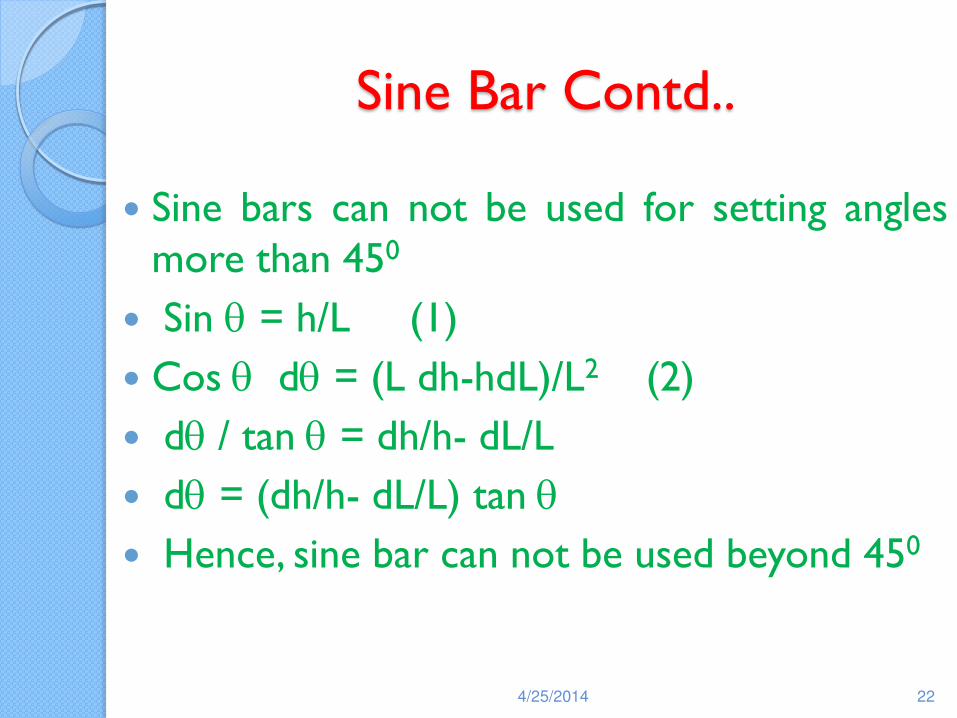
Sine Bar Contd..
Sine bars can not be used for setting angles more than 450
Sin q = h/L (1)
Cos q dq = (L dh-hdL)/L2 (2)
dq / tan q = dh/h- dL/L
dq = (dh/h- dL/L) tan q
Hence, sine bar can not be used beyond 450
4/25/2014 22
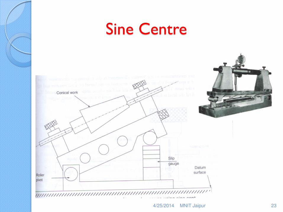
Sine Centre
4/25/2014 MNIT Jaipur 23
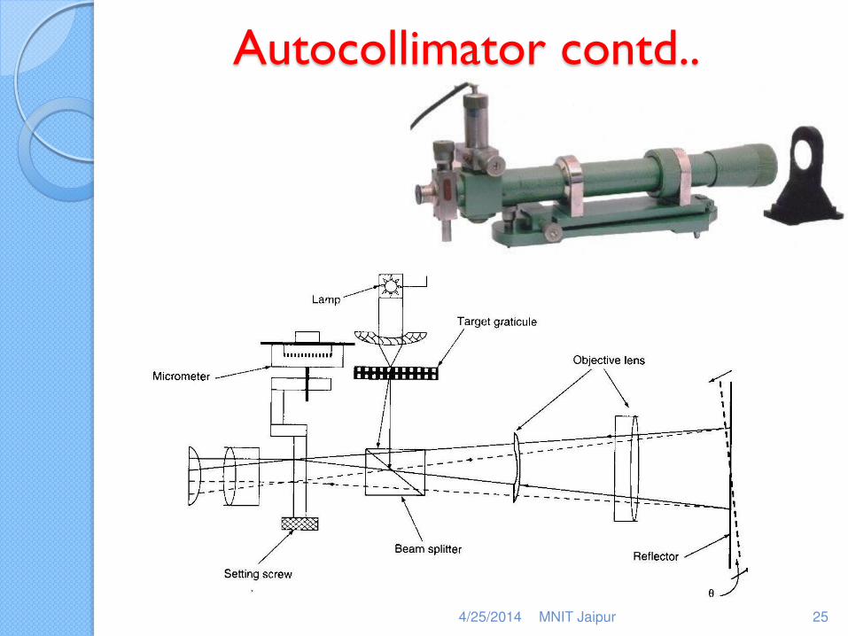
Autocollimator
Autocollimators are used to detect small misalignments
If a parallel beam of light is projected from the collimating lens and if a plane reflector R is set up normal to the direction of the beam, light will be reflected back along the same path and light will be brought back to focus exactly at the position of the light source
4/25/2014 MNIT Jaipur 24
Autocollimator contd..
4/25/2014 MNIT Jaipur 25
Autocollimator contd..
If the reflector is tilted through a small angle (q), the parallel beam will be reflected through twice the angle (2q) and would be brought to focus in the same plane as the light source but to one side of it. The image will not coincide but there will be a distance equal to focal length times the angle of reflection (2f q) where f is the focal length of the collimating lens.
4/25/2014 MNIT Jaipur 26
Autocollimator contd..
The distance between the reflector and the lens has no effect on the separation between the source and the image.
For high sensitivity, a long focal length is required
Although the distance of the reflector does not effect the reading, if it is moved too far back, reflected rays will miss the lens completely and no image will be formed.
4/25/2014 MNIT Jaipur 27
Types of Gear Inspection
Element by Element Inspection of Gear: Laborious, useful in error analysis, can’t be used by the gear manufacturers.
◦ Tooth thickness measurement
◦ Base pitch measurement
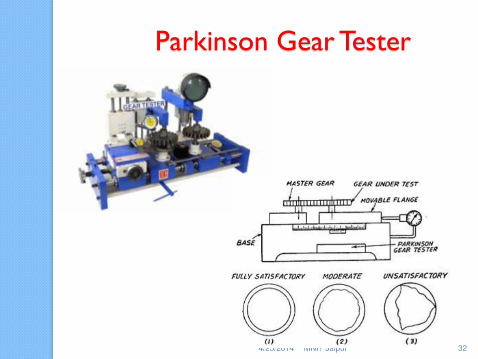
Composite Error Checking: Used in Gear Inspection by conducting only one test
Parkinson Gear Tester
4/25/2014 MNIT Jaipur 28
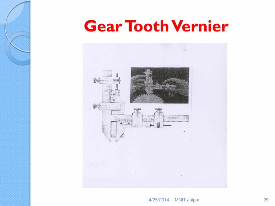
Gear Tooth Vernier
4/25/2014 MNIT Jaipur 29
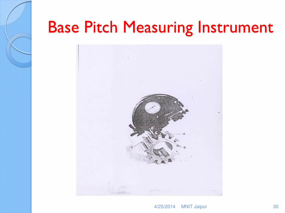
Base Pitch Measuring Instrument
4/25/2014 MNIT Jaipur 30
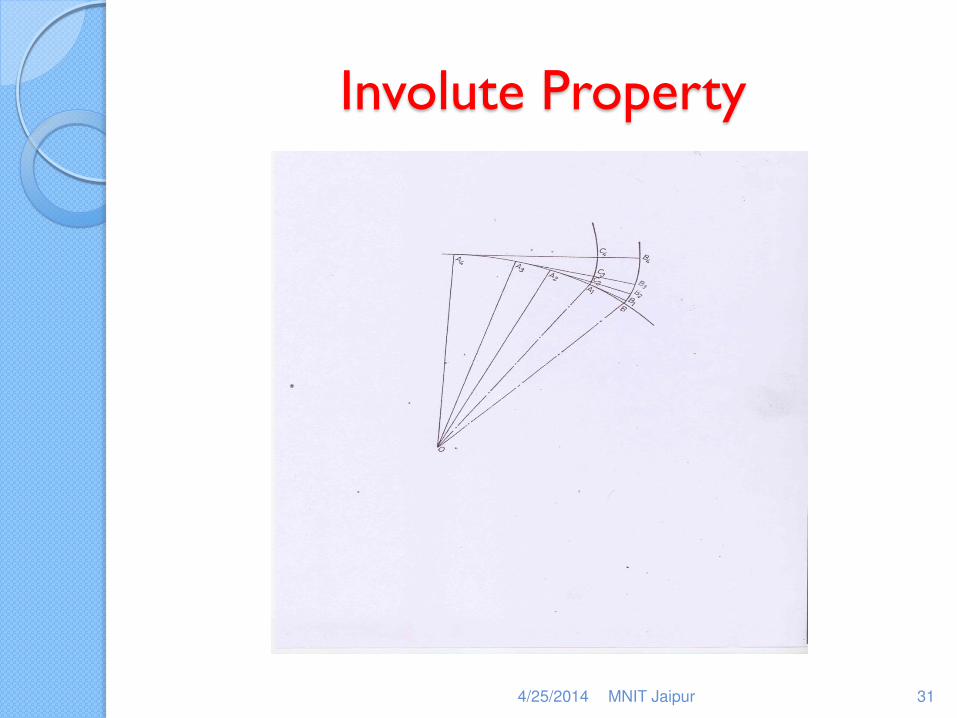
Involute Property
4/25/2014 MNIT Jaipur 31
4/25/2014 MNIT Jaipur 32
Parkinson Gear Tester
Thread Inspection - Terminology
Pitch: It is the distance measured parallel to the axis between the corresponding points on adjacent surfaces in the same axial plane.
Lead: It is the axial distance advanced by the thread in one revolution. Lead is equal to the same multiples of pitches as the number of starts.
4/25/2014 MNIT Jaipur 33
Thread Terminology Contd..
Included angle: It is the angle between the flanks of the thread measured in an axial plane.
Pitch diameter: It is the diameter of tee imaginary coaxial cylinder which intersects the surface of the thread in such a manner that the intercept on the generator of the cylinder is equal to half the pitch.
4/25/2014 MNIT Jaipur 34
Thread Terminology Contd..
Major Diameter: It is the diameter of imaginary coaxial cylinder that just touches the crests
Minor Diameter: It is the diameter of imaginary coaxial cylinder that just touches the roots
Helix Angle (q): tan q = p/p d
4/25/2014 MNIT Jaipur 35
Thread Inspection
Measurement of Major Diameter: Bench micrometer is normally used for this measurement.
It has measuring anvils so that the thread can be held between them.
It has fiducial indicator so that the required pressure can be applied for all the measurements
4/25/2014 MNIT Jaipur 36
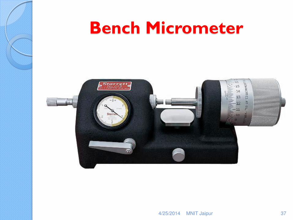
Bench Micrometer
4/25/2014 MNIT Jaipur 37
Thread Inspection
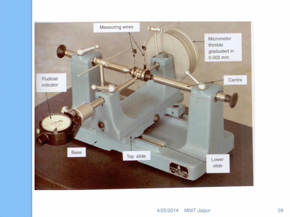
Measurement of Minor Diameter: Bench micrometer can not be used for Minor Diameter. So, another one, Floating Carriage micrometer is normally used for this measurement.
In this instrument, the thread is held between the centres so that the influence of helix angle can be nullified in this arrangement.
4/25/2014 MNIT Jaipur 38
4/25/2014 MNIT Jaipur 39
Thread Inspection
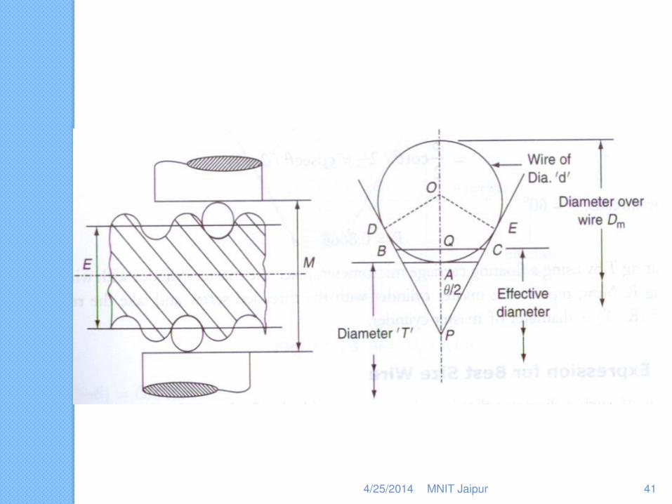
Measurement of Pitch (effective) Diameter: Again Floating Carriage micrometer is normally used for this measurement.
Here, the prisms used in the measurement of minor diameter are replaced by the steel wires whose size is chosen such that they pitch at the effective diameter.
4/25/2014 MNIT Jaipur 40
4/25/2014 MNIT Jaipur 41
Thread Inspection
Two wire Method: The two wires used should be identical in diameter and should pitch properly between the flanks.
Reading of the floating carriage micrometer is taken over these two wires so that the effective diameter can be calculated using the formula developed.
4/25/2014 MNIT Jaipur 42
Thread Inspection
Diameter of the best wires: If the wires used make contact exactly at the pitch diameter, then such wire is called the best wire. The diameter of such wire can be estimated from the formula.
Compression & Rake correction.
4/25/2014 MNIT Jaipur 43
Thread Inspection
Measurement of flank angle: Flank angle may be measured using Tool Maker’s Microscope with a goniometric head. This consists of glass screen with datum lines which can be rotated through 3600. The thread is mounted on centers and illuminated from below.
The microscope is mounted above the thread in such a way it can be swiveled to be in line with the thread helix and avoid interference of the image
4/25/2014 MNIT Jaipur 44
Thread Inspection
The datum lines in the microscope head are set to zero and the table is rotated until the crests of the thread coincide with the horizontal datum and the angle is measured.
4/25/2014 MNIT Jaipur 45
Measurement of Internal Threads
Measurement of Major Diameter: The major diameter of internal thread is normally measured using horizontal comparator fitted with ball end styli of radius less than the root radius of the thread to be measured.
When the thread is mounted on a comparator, it aligns itself with the axis of the machine and measurement would be done along the helix of the thread as indicated above.
4/25/2014 MNIT Jaipur 46
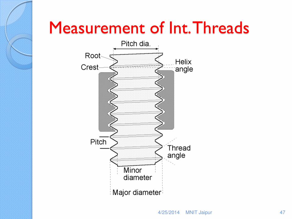
Measurement of Int. Threads
4/25/2014 MNIT Jaipur 47
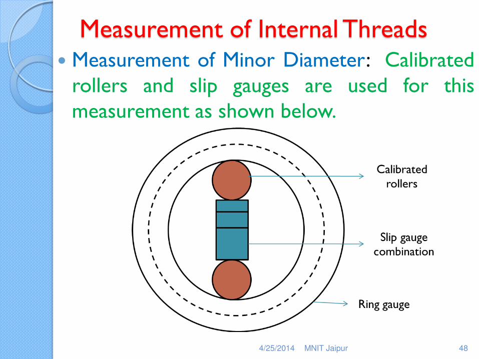
Measurement of Internal Threads Measurement of Minor Diameter: Calibrated
rollers and slip gauges are used for this measurement as shown below.
4/25/2014 MNIT Jaipur 48
Measurement of Internal Threads
Measurement of Effective Diameter: The effective diameter of internal thread is measured using the horizontal comparator using ball ended styli of the best size wire.
Measurement of Flank angle: The semi cast of the thread form may be made using dental plaster and measurement is obtained as done for external thread.
4/25/2014 MNIT Jaipur 49
Thread Gauges
Thread inspection can also be carried out using gauges designed according to the Taylors Principles:
Limit gauges for Internal threads:
◦ Full form Go Gauge
◦ Truncated Effective Diameter NOGO gauge
◦ Minor Diameter NOGO gauge
4/25/2014 MNIT Jaipur 50
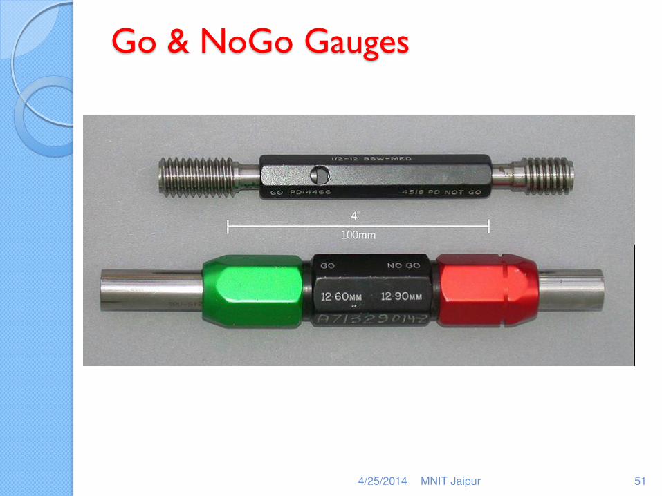
Go & NoGo Gauges
4/25/2014 MNIT Jaipur 51
Thread Gauges
Limit gauges for External threads:
◦ This is usually carried out using caliper type gauges
◦ Full form Go Gauge
◦ Truncated Effective Diameter NOGO gauge
◦ Major Diameter NOGO gauge
4/25/2014 MNIT Jaipur 52
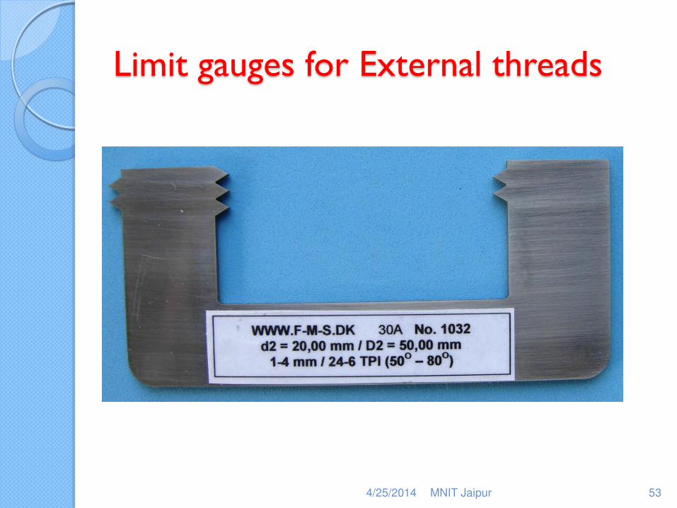
Limit gauges for External threads
4/25/2014 MNIT Jaipur 53
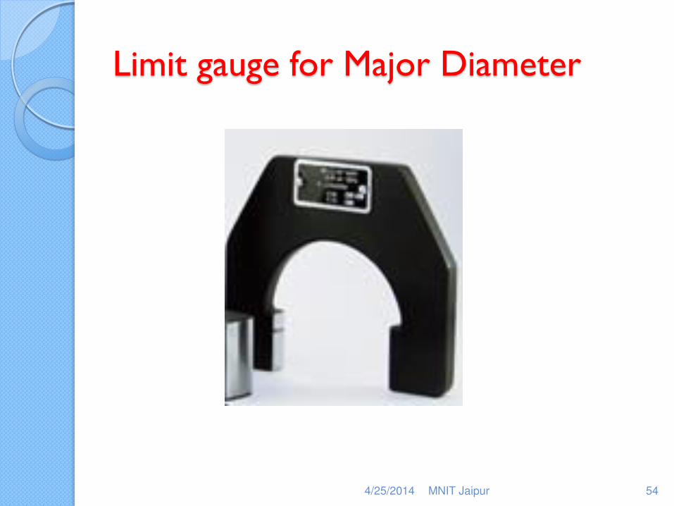
Limit gauge for Major Diameter
4/25/2014 MNIT Jaipur 54
Interferometry
Huygens theory proposes that light is considered as an electro-magnetic wave of sinusoidal form. The maximum disturbance is called amplitude and the velocity of transmission is represented by frequency.
4/25/2014 MNIT Jaipur 55
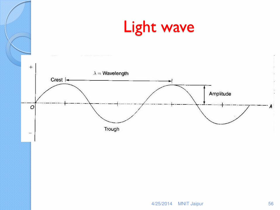
Light wave
4/25/2014 MNIT Jaipur 56
Interferometry Contd..
Interferometry is the branch of science which deals with the manner in which the monochromatic rays of light are combined by the lens system, usually the eye.
Let us see the effect of combining two rays A & B which are of same wave length
4/25/2014 MNIT Jaipur 57
Interferometry Contd..
4/25/2014 MNIT Jaipur 58
Interferometry Contd..
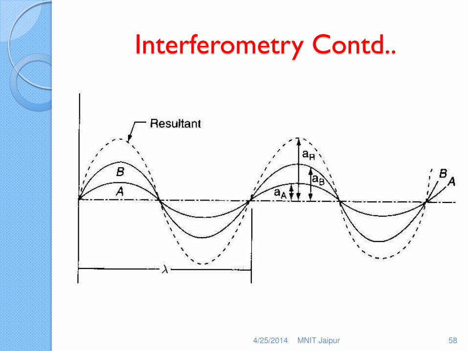
When they happen to be in phase, it results into the increased amplitude i.e. if the two rays of equal intensity are in phase, they augment each other and produce increased brightness.
If they are out of phase i.e. the path differs by the half the wave length, the combined effect is zero if the amplitudes are equal which results in darkness. This situation refers to the occurrence of interference.
4/25/2014 MNIT Jaipur 59
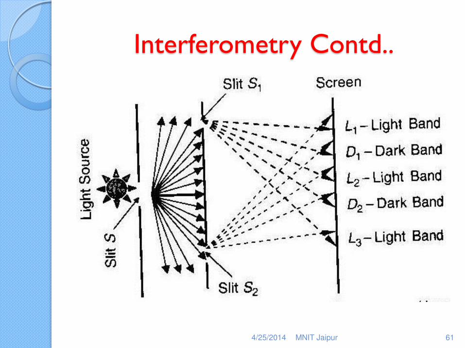
Interferometry Contd..
Interference of two rays may be demonstrated by considering the two rays emanating from the same source and travelled different distances so as to create the required path differences as shown below:
4/25/2014 MNIT Jaipur 60
Interferometry Contd..
4/25/2014 MNIT Jaipur 61
Interferometry Contd..
Another simple method of obtaining fringes is by illuminating an optical flat over a plane reflecting surface.
An optical flat is a disc of glass or quartz whose faces are highly polished and within few microns
4/25/2014 MNIT Jaipur 62
Interferometry Contd..
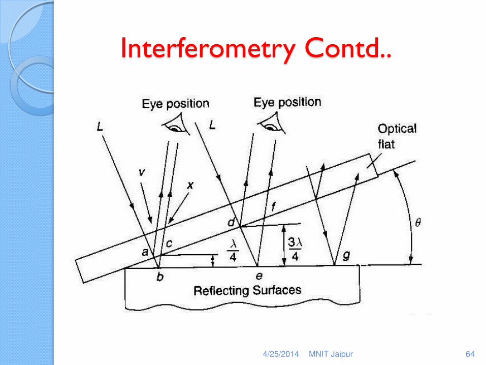
Consider a case when an optical flat is kept on the surface of a workpiece.
Due to some reason, it would not make an intimate contact but rests at some angle to the surface. If the optical flat is illuminated by monochromatic light, interference fringes would be observed.
4/25/2014 MNIT Jaipur 63
Interferometry Contd..
4/25/2014 MNIT Jaipur 64
Interferometry Contd..
Consider the two rays, one reflected from the bottom of the optical flat and other reflected from the top of the surface. If the path difference is half the wave length, then dark fringe is formed and again the dark fringe is formed when the path difference is 3 times half the wave length.
4/25/2014 MNIT Jaipur 65
Interferometry Contd..
The fringe pattern consists of alternate dark & bright straight bands in case of flat surface.
If the angle of inclination is small, ab=bc=l/4 and de=ef=3l/4
Change in separation between the optical flat and the surface is the difference between ab & de i.e. l/2.
Total change in elevation from the point of contact to the outer fringe= n l/2.
4/25/2014 MNIT Jaipur 66
Interferometry Contd..
When the optical flat is kept on a spherically convex/ concave surface, the fringe pattern consists of concentric circles. To distinguish between these two conditions, optical flat is pressed at a point away from the centre and if the centre of the fringe pattern gets shifted, then it is convex or if the fringe spacing reduces, it is convex.
4/25/2014 MNIT Jaipur 67
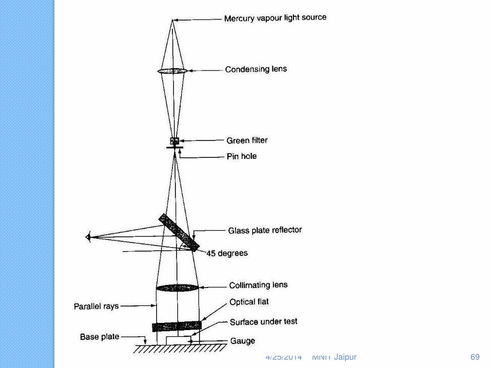
NPL Flatness Interferometer
The flatness of the surface under testing is measured by comparing it with an optical flat as discussed.
Mercury 198 is used as Mono-chromatic source of light.
The system consisting of optical flat, the surface under test, base plate, etc. are shown below:
4/25/2014 MNIT Jaipur 68
4/25/2014 MNIT Jaipur 69
NPL Flatness Interferometer
The instrument was designed by National Physical Laboratory.
It consists of Mercury vapor lamp whose radiations are passed through a green filter giving a monochromatic light. This light is focused on to a pin hole giving an intense point source of light which is the focal plane of collimating ;lens.
4/25/2014 MNIT Jaipur 70
NPL Flatness Interferometer
The parallel beam is directed on to the component to be tested via an optical flat so that interference fringes are formed which can be viewed directly above by means of thick glass plate semi-reflector set at 450 to the optical axis.
It should be noted that the optical flat is mounted on an adjustable tripod.
4/25/2014 MNIT Jaipur 71
NPL Flatness Interferometer
This instrument can be used to test parallelism between the two surfaces of the components.
The component to be tested is wrung on the surface plate.
The interference fringes are formed due to the rays reflected from the underside of the optical flat and due to those reflected from the surface of the component.
4/25/2014 MNIT Jaipur 72

NPL Flatness Interferometer
The fringes are also formed due to the rays reflected from the underside of the optical flat and due to those reflected from the surface of the base plate.
If the component is flat and parallel, the optical flat being equally inclined to both the surfaces, the fringe pattern from both the component & base plate are similar & equally spaced.
4/25/2014 MNIT Jaipur 73
NPL Flatness Interferometer
When the component is flat but not parallel to the base plate, fringe pattern is straight, parallel but not equally spaced.
4/25/2014 MNIT Jaipur 74