comparison of fcc and 3gpp requirements for 3.5 ghz of fcc and 3gpp requirements for 3.5 ghz •...
TRANSCRIPT

1 © Nokia 2015
Comparison of FCC and 3GPP requirements for 3.5 GHz
• Petri Vasenkari • 10-09-2015 • V1.0

2
Studying use of 3GPP TD-LTE bands 42 & 43
E-UTRA Operating
Band
Uplink (UL) operating band BS receive UE transmit
Downlink (DL) operating band BS transmit UE receive
Duplex Mode
FUL_low – FUL_high FDL_low – FDL_high
33 1900 MHz – 1920 MHz 1900 MHz – 1920 MHz TDD
34 2010 MHz – 2025 MHz 2010 MHz – 2025 MHz TDD
35 1850 MHz – 1910 MHz 1850 MHz – 1910 MHz TDD
36 1930 MHz – 1990 MHz 1930 MHz – 1990 MHz TDD
37 1910 MHz – 1930 MHz 1910 MHz – 1930 MHz TDD
38 2570 MHz – 2620 MHz 2570 MHz – 2620 MHz TDD 39 1880 MHz – 1920 MHz 1880 MHz – 1920 MHz TDD 40 2300 MHz – 2400 MHz 2300 MHz – 2400 MHz TDD 41 2496 MHz 2690 MHz 2496 MHz 2690 MHz TDD 42 3400 MHz – 3600 MHz 3400 MHz – 3600 MHz TDD 43 3600 MHz – 3800 MHz 3600 MHz – 3800 MHz TDD 44 703 MHz – 803 MHz 703 MHz – 803 MHz TDD
Table 5.5-1 E-UTRA operating bands
3GPP TDD bands 42 and 43 overlap the 3.5 GHz frequency range which in US is inteded for mobile broadband use. FCC calls this band as “Citizens Broadband Radio Service (CBRS)” and it is regulated under new Part 96 of FCC’s Rules.

3
Receiver requirements

4
FCC receiver requirement for 3.5 GHz band
(f) Reception Limits: Priority Access Licensees must accept adjacent channel and in-band blocking interference (emissions from other authorized Priority Access or GAA CBSDs transmitting between 3550 and 3700 MHz) up to a power spectral density level not to exceed -40 dBm in any direction with greater than 99% probability when integrated over a 10 megahertz reference bandwidth, with the measurement antenna placed at a height of 1.5 meters above ground level, unless the affected Priority Access Licensees agree to an alternative limit and communicates that to the SAS.

5
3GPP ACS and blocking
Adja
cent
cha
nnel
/ AC
S
Seco
nd A
djac
ent c
hann
el /
In-b
and
bloc
king
Cas
e 1
Third
Adj
acen
t cha
nnel
/ In
-ban
d bl
ocki
ng C
ase
2
BandEdge
OOB BlockingRange 1
OOB BlockingRange 2
OOB BlockingRange 3
Min 85 MHz
Min 60 MHz
Min15
MHz
Pinterferer
10 MHz LTE Carrier
-56 dbm /5 MHz
-44 dbm /5 MHz
-30 dbm /5 MHz
-15 dbm /5 MHz
7.5 M12.5 M
2.5 M
2.5 M
Wanted signalREFSENS + 6 dB
= -91 dBm for band 4
-58 dbm /5 MHz
Up to 12.75 G
FCC and 3GPP ACS and blocking requirements cannot be fully compared as there are some difference how they are defined. However some conlusions can be derived. Firstly FCC requirements apply to all wanted signal levels as 3GPP has some offset to RESENS. Offset dependes on requirement. Secondly FCC interferer is 10 MHz as for 3GPP it is typically 5 MHz.

6
3GPP ACS
In 3GPP specifications user terminal has to be able to tolerate adjacent channel interference which has 31.5 dB higher power. There are 2 different test points where this is verified. Case 1 where wanted signal is REFSENS + 14 dB and Case 2 where interferer is -25 dBm. Neither of these is aligned with FCC requirement. It is anyway clear that FCC requirement is much tighter than 3GPP requirement.
Rx Parameter Units Channel bandwidth 1.4 MHz 3 MHz 5 MHz 10 MHz 15 MHz 20 MHz
Power in Transmission Bandwidth Configuration
dBm
REFSENS + 14 dB
PInterferer
dBm REFSENS +45.5dB
REFSENS +45.5dB
REFSENS +45.5dB
REFSENS +45.5dB
REFSENS +42.5dB
REFSENS
+39.5dB BWInterferer MHz 1.4 3 5 5 5 5 FInterferer (offset) MHz 1.4+0.0025
/ -1.4-0.0025
3+0.0075 /
-3-0.0075
5+0.0025 /
-5-0.0025
7.5+0.0075 /
-7.5-0.0075
10+0.0125 /
-10-0.0125
12.5+0.0025
/ -12.5-0.0025
Table 7.5.1-2: Test parameters for Adjacent channel selectivity, Case 1
Example for Band 42 Case 1: Wanted 10 MHz signal power level = - 96 dBm + 14 dB = - 82 dBm Interferer = -50.5 dBm Case 2: Wanted 10 MHz = -56.5 dBm Interferer = - 25 dbm

7
In-band blocking
E-UTRA band
Parameter Unit Case 1 Case 2 Case 3 Case 4 PInterferer dBm -56 -44
Void Void
FInterferer (offset) MHz
=-BW/2 – FIoffset,case
1 &
=+BW/2 + FIoffset,case
1
≤-BW/2 – FIoffset,case 2 &
≥+BW/2 + FIoffset,case
2
All bands FInterferer MHz (Note 2) FDL_low – 15
to FDL_high + 15
NOTE 1: For certain bands, the unwanted modulated interfering signal may not fall inside the UE receive band, but within the first 15 MHz below or above the UE receive band
NOTE 2: For each carrier frequency the requirement is valid for two frequencies: a. the carrier frequency -BW/2 - FIoffset, case 1 and b. the carrier frequency +BW/2 + FIoffset, case 1
NOTE 3: FInterferer range values for unwanted modulated interfering signal are interferer center frequencies.
3GPP has defined two different in-band blocking requirements. Case 1 represents second adjacent channel (5 MHz) interferer which has -56 dBm level. Case 2 interferer has power level of -44 dbm and can be located in frequency range spaning from third adjacent up to a frequency where out-of band blocking requirement strarts. Wanted signal level is REFSENS +6 dB. FCC requirement is much tighter than 3GPP requirement
Table 7.6.1.1-2: In-band blocking

8
Out-of-band blocking
Table 7.6.2.1-2: Out of band blocking
3GPP out-of-band blocking range 1 requirement starts 15 MHz out of band edge with an interferer level of -44 dBm. Range 2 interferer with – 30 dBm power level starts from 60 MHz out of band edge up to 85 MHz. When interferer offset is larger than 85 MHz then the power level is 15 dBm. For 3.5 GHz bands 3GPP has relaxed range 3 interferer level (note 2) to allow UE implementation using a single filter for bands 42 and 43. Wanted signal level is REFSENS + 6 dB. FCC requirement is tighter than 3GPP range 1 reguirement. 3GPP out of band range 2 and range 3 requirements are tighter than FCC ACS and in-band requirement.
E-UTRA band
Parameter Units Frequency Range 1 Range 2 Range 3 Range 4
PInterferer dBm -44 -30 -15 -15 1, 2, 3, 4, 5, 6, 7, 8, 9, 10, 11, 12, 13, 14, 17, 18, 19, 20, 21, 22, 23, 24, 25, 26, 27, 28, 30, 31, 33, 34, 35, 36, 37, 38, 39, 40, 41, 42 (NOTE 2), 43 (NOTE 2), 44
FInterferer (CW) MHz
FDL_low -15 to FDL_low -60
FDL_low -60 to FDL_low -85
FDL_low -85 to 1 MHz -
FDL_high +15 to FDL_high + 60
FDL_high +60 to FDL_high +85
FDL_high +85 to +12750 MHz -
2, 5, 12, 17 FInterferer MHz - - - FUL_low - FUL_high
NOTE 1: For the UE which supports both Band 11 and Band 21 the out of blocking is FFS. NOTE 2: The power level of the interferer (PInterferer) for Range 3 shall be modified to -20 dBm for FInterferer > 2800
MHz and FInterferer < 4400 MHz.

9
Applicability of 3GPP blocking requirements for US 3.5 GHz frequency range

10
Conclusions
•FCC Blocking requirement is quite much tighter than what GPP has for UE
•Currently 3GPP blocking requirements are same for all bands (small deviation for bands 42/43 to enable multiple filtering soltions to be used)
•Creating a new band does not solve the blocking issue as current RF ICs are not linear enough and filtering does not help as requirement is for inband
•If the requirement is not changes RF IC vendors need to develop dedicated RF IC with better linearity and filtering (not sure if feasible)
•Even in case of new band it would be extremely important to be able to use same RF IC technology as for any other band and same filtering solution as for bands 42/43. This would enable faster deployment and more affordable prices due to economics of scale.

11
Transmitter requirements

12
Emission Limits for EUDs (Rule Part 96.41(e))
Part 96.41(e) 3.5 GHz Emissions and Interference Limits: (1) General protection levels. Except as otherwise specified below, for channel and frequency assignments made by the SAS to CBSDs, the power of any emission outside the fundamental emission (whether in or outside of the authorized band) shall not exceed: •-13 dBm/MHz from 0 to 10 MHz from the assigned channel edge •-25 dBm/MHz beyond 10 MHz from the assigned channel edge down to 3530 MHz and up to 3720 MHz •-40 dBm/MHz below 3530 MHz and above 3720 MHz
13
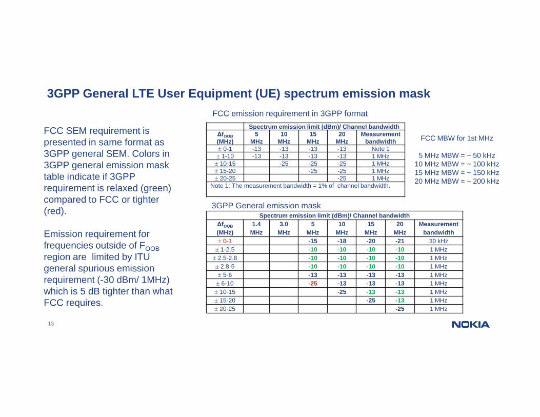
3GPP General LTE User Equipment (UE) spectrum emission mask
Spectrum emission limit (dBm)/ Channel bandwidth ΔfOOB (MHz)
1.4 MHz
3.0 MHz
5 MHz
10 MHz
15 MHz
20 MHz
Measurement bandwidth
0-1 -15 -18 -20 -21 30 kHz 1-2.5 -10 -10 -10 -10 1 MHz
2.5-2.8 -10 -10 -10 -10 1 MHz 2.8-5 -10 -10 -10 -10 1 MHz 5-6 -13 -13 -13 -13 1 MHz
6-10 -25 -13 -13 -13 1 MHz 10-15 -25 -13 -13 1 MHz 15-20 -25 -13 1 MHz 20-25 -25 1 MHz
Spectrum emission limit (dBm)/ Channel bandwidth ΔfOOB (MHz)
5 MHz
10 MHz
15 MHz
20 MHz
Measurement bandwidth
0-1 -13 -13 -13 -13 Note 1 1-10 -13 -13 -13 -13 1 MHz
10-15 -25 -25 -25 1 MHz 15-20 -25 -25 1 MHz 20-25 -25 1 MHz
Note 1: The measurement bandwidth = 1% of channel bandwidth.
3GPP General emission mask
FCC emission requirement in 3GPP format
FCC MBW for 1st MHz
5 MHz MBW = ~ 50 kHz 10 MHz MBW = ~ 100 kHz 15 MHz MBW = ~ 150 kHz 20 MHz MBW = ~ 200 kHz
FCC SEM requirement is presented in same format as 3GPP general SEM. Colors in 3GPP general emission mask table indicate if 3GPP requirement is relaxed (green) compared to FCC or tighter (red). Emission requirement for frequencies outside of FOOB region are limited by ITU general spurious emission requirement (-30 dBm/ 1MHz) which is 5 dB tighter than what FCC requires.

14
Frequency band (MHz)
Channel bandwidth / Spectrum emission limit (dBm)
MBW
5, 10, 15, 20 MHz
3400 ≤ f ≤ 3800 -23 (NOTE 1, NOTE 3) 5 MHz -40 (NOTE 2) 1 MHz
NOTE 1: This requirement applies within an offset between 5 MHz and 25 MHz from the lower and from the upper edge of the channel bandwidth, whenever these frequencies overlap with the specified frequency band.
NOTE 2: This requirement applies from 3400 MHz to 25 MHz below the lower E-UTRA channel edge and from 25 MHz above the upper E-UTRA channel edge to 3800 MHz.
NOTE 3: This emission limit might imply risk of harmful interference to UE(s) operating in the protected operating band
3GPP Additional spurious emissions for existing NS_22
If general emission mask does not provide enough protection it is possible to define tighter emission requirements which are indicated with network signalling. Currently for bands 42 and 43 there is one NS signalling defined i.e. NS_22. 3GPP NS_22 requirement which is intended for band 42 and 43 coexistence cases and also can be used when networks are not synchronized inside the bands 42 and 43. UE is allowed to use Additional transmission power reduction (A-MPR) when NS_22 is signaled.
Additional-Maximum Power Reduction (A-MPR) for NS_22

15
Carrier
51 25
-13 dBm / 1 MHz
-25 dBm / 1 MHz
-40 dBm / 1 MHz
FCC
3GPP
Offsets 5 -25 MHz3GPP requirement for NS_22
Is -23 dBm / 5 MHz (~-30 dBm / 1 MHz)
FCC limits
3GPP Offsets 1 -5MHz
General SEM-10 dBm / 1 MHz
3GPP Offsets 0-1 MHzGeneral SEM
Depends on CH BW3530 MHz or 3720
MHz
10
FCC Offsets 0-1 MHzMeasurement BW = 1% of
channel bandwidth
Comparison of FCC Emission requirement to 3GPP NS 22 requirement
FCC mask is tighter than 3GPP mask for: 0 - 5 MHz offset and below 3530 / above 3720MHz.
When "NS 22" is indicated in the cell, the power of any UE emission shall not exceed the levels specified by the red curve

16
Full 10 MHz LTE carrier at lowest frequency position
No A-MPR is required for full 10 MHz carrier when 1% MBW is used for first MHz outside channel edge. 4 dB margin to -40 dBm requirement.

17
10 MHz LTE carrier with PUCCH (1RB) at lowest frequency position
No A-MPR is required 1.7 dB margin to -13 dBm requirement.

18
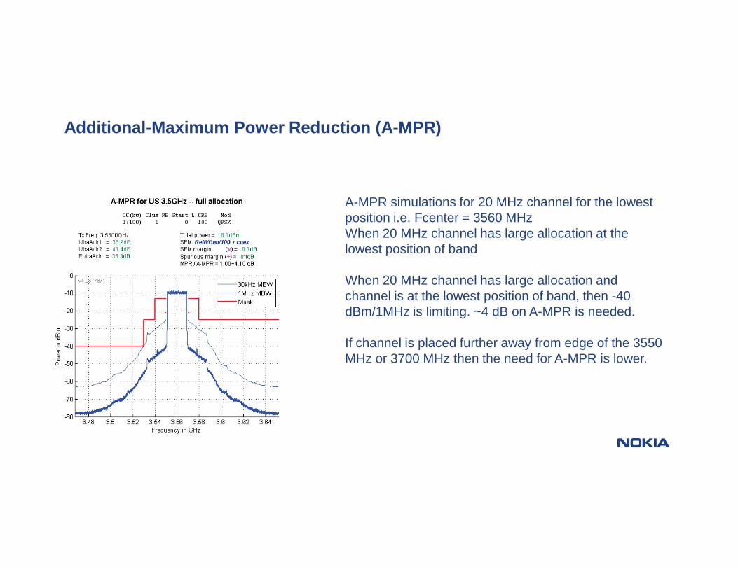
Additional-Maximum Power Reduction (A-MPR)
A-MPR simulations for 20 MHz channel for the lowest position i.e. Fcenter = 3560 MHz 1 RB transmission at the edge of the channel For 20 MHz channel with 1 RB transmission at the edge of the channel, the -25 dBm/1MHz requirement is the limiting factor. 3 dB of power reduction is needed.
19
Additional-Maximum Power Reduction (A-MPR)
A-MPR simulations for 20 MHz channel for the lowest position i.e. Fcenter = 3560 MHz When 20 MHz channel has large allocation at the lowest position of band When 20 MHz channel has large allocation and channel is at the lowest position of band, then -40 dBm/1MHz is limiting. ~4 dB on A-MPR is needed. If channel is placed further away from edge of the 3550 MHz or 3700 MHz then the need for A-MPR is lower.

20
• It is possible to define new NS-value for bands 42/43 to accommodate FCC emission requirements if those are different from what 3GPP has now defined for bands 42/43.
• Only new UE designs can understand new NS-value
Conclusions
