comparison of multi-storey cross-laminated timber and timber frame ... · comparison of...
TRANSCRIPT

Comparison of multi-storey cross-laminated timber and timber frame buildingsby in-situ modal analysis
This is the author’s accepted version - Full paper athttp://dx.doi.org/10.1016/j.conbuildmat.2015.09.056
Thomas Reynoldsa,, Daniele Casagrandeb, Roberto Tomasib
aUniversity of Cambridge, Department of Architecture, 1 Scroope Terrace, Cambridge CB2 1PXbDepartment of Civil, Environmental and Mechanical Engineering, University of Trento
Abstract
The dynamic properties of two common structural systems for multi-storey timber buildings are compared throughin-situ testing of completed buildings. The two five-storey buildings examined are identical except for their structuralsystem, which in one is sheathed stud-and-rail timber construction, and in the other a cross-laminated timber panelsystem. Both also have a reinforced-concrete core located at the centre of one edge of the rectangular plan of eachbuilding. An output-only modal analysis method was used to identify the modal properties of the buildings: therandom decrement technique was applied to the stochastic measured response, and then the time-domain randomdecrement signature was used for modal analysis by the Ibrahim Time Domain method. The natural frequencies,damping ratios and mode shapes of the first three vibration modes of the buildings were identified, and comparedwith those modeled based on the properties of the core and timber walls. The variations in properties between the twobuildings are discussed. The two structures show very similar natural frequencies and damping ratios, suggesting thatthey could perhaps be considered as the same class of building in design for lateral movement.
Keywords: timber, multi-storey, modal anlaysis, damping
1. Introduction
Timber construction systems have in recent yearsbeen increasingly used in multi-storey residential con-struction in Europe, which represents a change from theone- and two-storey houses responsible for the bulk ofstructural use of timber over the last century. An ex-ample of this is the choice of the Trentino social hous-ing company ITEA to build two five-storey multi-familyapartment buildings in Trento (Italy) using two differenttimber wall systems: timber frame (TF) and cross lami-nated timber (CLT). An external view of the two build-ings is shown in Figure 1. The design and the construc-tion of these two buildings are the result of an interna-tional collaboration between ITEA and the Canadian so-cial housing company Quebec Societe D’Habitation inorder to evaluate and compare timber construction sys-tems for social housing from the two countries. Sincethe two buildings have identical floor plans, layouts and
Email address: [email protected] (Thomas Reynolds)
finishes and differ only in their structural system, theypresent a unique opportunity for comparison of the twokey forms of timber construction in economic and en-gineering terms. One parameter for comparison is theirdynamic behaviour under lateral loads.
For the construction of larger and taller timber build-ings, it is necessary to understand the dynamic be-haviour of timber structural systems. This is becausemovements, which may be acceptable for small heightsand spans, are magnified in large structures, and maycause discomfort to building occupants, damage to non-structural elements, or increased loads on elements.These structures behave nonlinearly, due to the embed-ment behaviour of the nails and screws in their connec-tions, as well as the rigid-body rotations of panels, andso their dynamic behaviour depends on the amplitudeof the exciting force. Research must therefore addressdynamic behaviour in both the serviceability limit state,under loads such as wind and footfall, and for the ulti-mate limit state, under seismic or wind loads. In order tomodel and predict the response of structures to such dy-
Preprint submitted to Construction and Building Materials January 11, 2016
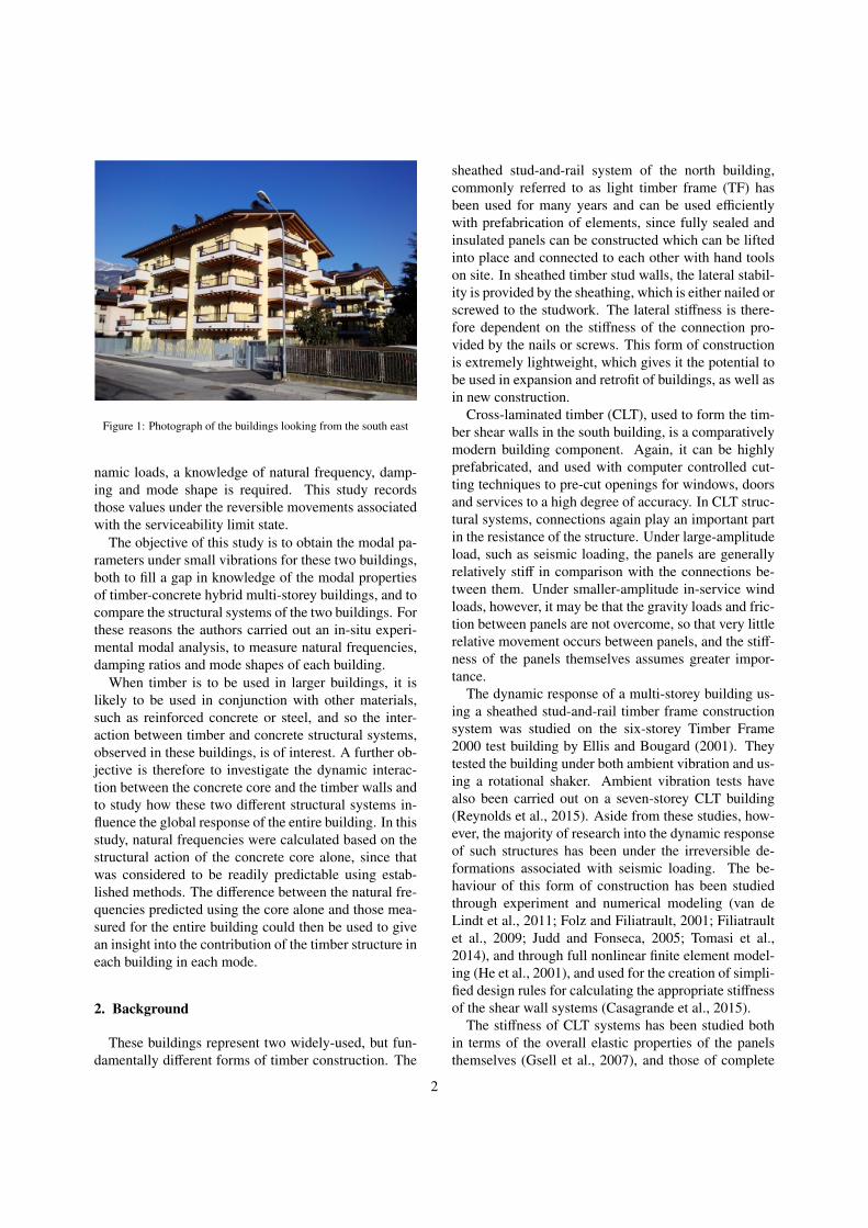
Figure 1: Photograph of the buildings looking from the south east
namic loads, a knowledge of natural frequency, damp-ing and mode shape is required. This study recordsthose values under the reversible movements associatedwith the serviceability limit state.
The objective of this study is to obtain the modal pa-rameters under small vibrations for these two buildings,both to fill a gap in knowledge of the modal propertiesof timber-concrete hybrid multi-storey buildings, and tocompare the structural systems of the two buildings. Forthese reasons the authors carried out an in-situ experi-mental modal analysis, to measure natural frequencies,damping ratios and mode shapes of each building.
When timber is to be used in larger buildings, it islikely to be used in conjunction with other materials,such as reinforced concrete or steel, and so the inter-action between timber and concrete structural systems,observed in these buildings, is of interest. A further ob-jective is therefore to investigate the dynamic interac-tion between the concrete core and the timber walls andto study how these two different structural systems in-fluence the global response of the entire building. In thisstudy, natural frequencies were calculated based on thestructural action of the concrete core alone, since thatwas considered to be readily predictable using estab-lished methods. The difference between the natural fre-quencies predicted using the core alone and those mea-sured for the entire building could then be used to givean insight into the contribution of the timber structure ineach building in each mode.
2. Background
These buildings represent two widely-used, but fun-damentally different forms of timber construction. The
sheathed stud-and-rail system of the north building,commonly referred to as light timber frame (TF) hasbeen used for many years and can be used efficientlywith prefabrication of elements, since fully sealed andinsulated panels can be constructed which can be liftedinto place and connected to each other with hand toolson site. In sheathed timber stud walls, the lateral stabil-ity is provided by the sheathing, which is either nailed orscrewed to the studwork. The lateral stiffness is there-fore dependent on the stiffness of the connection pro-vided by the nails or screws. This form of constructionis extremely lightweight, which gives it the potential tobe used in expansion and retrofit of buildings, as well asin new construction.
Cross-laminated timber (CLT), used to form the tim-ber shear walls in the south building, is a comparativelymodern building component. Again, it can be highlyprefabricated, and used with computer controlled cut-ting techniques to pre-cut openings for windows, doorsand services to a high degree of accuracy. In CLT struc-tural systems, connections again play an important partin the resistance of the structure. Under large-amplitudeload, such as seismic loading, the panels are generallyrelatively stiff in comparison with the connections be-tween them. Under smaller-amplitude in-service windloads, however, it may be that the gravity loads and fric-tion between panels are not overcome, so that very littlerelative movement occurs between panels, and the stiff-ness of the panels themselves assumes greater impor-tance.
The dynamic response of a multi-storey building us-ing a sheathed stud-and-rail timber frame constructionsystem was studied on the six-storey Timber Frame2000 test building by Ellis and Bougard (2001). Theytested the building under both ambient vibration and us-ing a rotational shaker. Ambient vibration tests havealso been carried out on a seven-storey CLT building(Reynolds et al., 2015). Aside from these studies, how-ever, the majority of research into the dynamic responseof such structures has been under the irreversible de-formations associated with seismic loading. The be-haviour of this form of construction has been studiedthrough experiment and numerical modeling (van deLindt et al., 2011; Folz and Filiatrault, 2001; Filiatraultet al., 2009; Judd and Fonseca, 2005; Tomasi et al.,2014), and through full nonlinear finite element model-ing (He et al., 2001), and used for the creation of simpli-fied design rules for calculating the appropriate stiffnessof the shear wall systems (Casagrande et al., 2015).
The stiffness of CLT systems has been studied bothin terms of the overall elastic properties of the panelsthemselves (Gsell et al., 2007), and those of complete
2
structural systems including connections (Vessby et al.,2009). The seismic performance of the components andsystems in CLT buildings was widely studied (Gavricet al., 2015; Fragiacomo et al., 2011), and full-scaleshaking table tests of buildings were carried out underthe SOFIE project (Ceccotti et al., 2013). Under seismicloads, the movement is dominated by deformation in theconnections, which are relatively flexible in comparisonwith the panels themselves. The response of the build-ings can be expected to be different under the smallervibration due to wind load since, in these conditions,the forces are transferred between panels primarily byfriction and normal edge forces, and connections maybe much more lightly loaded. Further research is there-fore required to determine those parameters.
Modal analysis of structures can be carried out usingrecords of both excitation force and output vibration, ex-pressed as either acceleration, displacement or velocity.In these tests, however, the building owners were notwilling to allow a shaker or other device to be attachedto the structure to provide the necessary excitation force,and so for this test series, an output-only modal analysistechnique was used. Such techniques have been appliedto buildings and bridges (Brownjohn et al., 2010; Cunhaand Caetano, 2006; Magalhaes et al., 2012; Foti et al.,2012), and rely on the stochastic excitation produced bythe ambient conditions of wind.
In this study, we focus on the small-amplitude vi-bration observed in these buildings under ambient windconditions. The modal properties observed under suchconditions are most directly applicable as an indicationof the sensitivity of these buildings, and taller multi-storey buildings of similar form, to wind-induced vi-bration. They also provide an estimate of the as-builtdynamic properties of the structure which, bearing inmind the expected variation in deformation mechanismsdescribed above, may be a useful indication of the dy-namic properties relevant to seismic excitation. Sincetests on completed structures must be limited to re-versible deformations, this type of test is an importanttool for assessment of their sensitivity to earthquakes.
3. Description of test buildings
The tested buildings have 5 storeys with a total heightof 15.6 m and are approximately rectangular in plan(14.7 m x 18.5 m) , with the reinforced concrete staircore at the centre of the long edge. A plan of the build-ings, indicating their structure, is shown in Figure 2, andan elevation showing the floor levels is given in Figure3.
In the north (TF) building, the walls are made with120 mm x 180 mm solid timber studs at a spacing of625 mm. Oriented Strain Board (OSB/3) sheathing pan-els, 18 mm thick, on both sides of the wall were used toprovide lateral stability, connected to the wood frame bymeans of ring nails (3.1 mm x 60 mm) with a spacing onthe panel perimeter of 50 mm. A timber-concrete com-posite structure was used for the floors, connecting 100mm x 200 mm glulam beams (with a spacing of 58 cm)to a 50 mm thick concrete slab with vertical screws. Thefloors are connected to the core by steel bars designed totransfer seismic forces. The bars are cast into the 50 mmconcrete slab on top of the floor, and into the concretecore.
In the south (CLT) building, the walls were made with5-layer CLT panels with a thickness of 153 mm for theground and the first floor and of 133 mm for the upperfloors. Floors were made with 5-layer CLT panel witha height of 153 mm and a width of 1.70 m transversallyconnected by 45°inclined screws. The CLT floor panelswere screwed to 10x24 cm glulam beam which in turnwere bolted to the concrete core.
Both buildings may be described as having plat-form construction, since each wall is interrupted at eachstorey level. In the CLT building, the floors are loadedperpendicular to the grain at each storey. In the TFbuilding, the timber beams of the floor are not placedon the top plate of timber frame walls, but are con-nected to it with screws inclined at 45°. Perpendicu-lar to grain loading therefore only occurs in the top andbottom plate of the walls.
In both buildings, the rigid-body rotation and the slid-ing of each walls were prevented by hold-downs, on thecorner of the walls, and angle brackets respectively, de-signed to bear both wind load and seismic load. Bothbuildings have a 5.20 m x 5.60 m reinforced concretecore (wall thickness 200 mm), which contributes to theresistance of vertical and lateral loads working togetherwith the timber shear walls. The buildings can thereforebe described as timber-concrete hybrid structures.
The total length of shear walls running in a particulardirection may be considered as an indication of the stiff-ness of the building in that direction. The total lengthof shear walls in both buildings is 22.8 m and 17.1 malong the y (north-south) and x (east-west) directionsrespectively. In the north-south direction, the greater to-tal length of the two concrete walls (11.20 m) and thegreater total length of the timber shear wall (22.8 m)suggests that the building would be stiffer, and thereforehave a higher natural frequency, than in the east-westdirection. Moreover, because of the eccentric locationof the concrete core, it is expected than the translation
3

Reinforced concrete wall
Vertical timber column or studGrain orientation in outer layerof CLT panels
Timber structural wall
N
Figure 2: Plan sections of the TF (left) and CLT (right) tested buildings, showing structural elements
2.98m
2.98m
2.98m
2.98m
15.60m
4th
3rd
2nd
1st
Figure 3: Schematic elevation of a building showing the levels for measurement of acceleration
4
Table 1: Weight of CLT building
Floors Walls Total Area(kN) (kN) (kN) (m2)
Ground Floor 944.1 271.9 1216.0 223P1 944.1 244.9 1189.0 223P2 944.1 252.1 1196.2 223P3 843.5 218.9 1062.4 223
Roof 366.4 84.9 451.3 352
Total weight 5114.9 kN
Table 2: Weight of TF building
Floors Walls Total Area(kN) (kN) (kN) (m2)
Ground Floor 1030.9 220.3 1251.2 223P1 1030.9 204.4 1235.4 223P2 1030.9 155.8 1186.8 223P3 931.7 125.4 1057.1 223
Roof 345.5 71.8 417.2 352
Total weight 5147.6 kN
mode shape in the east-west direction will be coupledwith the torsional mode shape. Because the symmetryof the building in the north-south direction, no torsionaleffect was expected in this direction.
The weight of each building is summarised in Table1 and Table 2. It can be seen that the mass of the twobuildings is almost identical, but the distribution of themass is slightly different. The two buildings have thesame non-structural elements in the floor, so any dif-ference in mass is due to the structure and the walls.The higher mass in the walls of the CLT building, andtherefore at its perimeter, would be expected to reducethe frequency of the first torsional mode of vibration.The mass in the TF building is also biased slightly moretowards the higher levels, which would be expected toreduce the lateral and torsional frequencies.
4. Methods
The tests used a set of 10 piezoelectric accelerome-ters, mounted to measure acceleration in 2 perpendicu-lar horizontal directions in 5 locations. The accelerome-ters had a sensitivity of 10 V/g, a frequency range from0.2 Hz to 1500 Hz and a measurement range of ± 4.9m/s2. Two pairs of accelerometers (A1 to A4) were kept
in position to provide a pair of possible reference loca-tions, while the other three pairs (from A5 to A10) weremoved to measure at the four corners of the buildings ateach of the four above-ground floors. In order to recordthe signals from all four corners in both direction for allthe floors (the roof was excluded), 5 tests were carriedout for each building. A sampling frequency of 600 Hzwas adopted with an appropriate anti-aliasing filter. Themean signal duration was approximately 30 minutes.
In Table 3 the location and the direction of each chan-nel is shown for all 5 test set-ups. In Figure 4 the ac-celerometer locations and directions for test set-up num-ber 2 are shown. The measured data from each of thesetests was first filtered using a 5-pole Butterworth band-pass filter, with pass band between 0.1 Hz and 30 Hz.It was then analysed using the random decrement tech-nique. This resulted in a set of coordinated randomdecrement signatures for each test.
The random decrement technique (H Cole, 1968) av-erages a group of data segments, each starting at thepoint where the signal crosses a chosen trigger level.Segments of data were rejected, and not used in the av-eraging process, if their standard deviation was morethan 10% higher or lower than the standard deviationof the complete signal. This helped to ensure stationar-ity of modal properties in the segments being averaged,since the segments being averaged all had similar ampli-tude, and would therefore be expected to exhibit similarmodal properties.
The Ibrahim Time Domain (ITD) method was thenused to extract modal parameters from the set of randomdecrement signatures, giving a set of natural frequen-cies, damping ratios and partial mode shapes for eachtest. The partial mode shapes could then be combined,by scaling them so that the amplitude of the referencechannels in that mode was the same for the partial modeshapes from each test.
The sensitivity of the results to the random decrementtrigger level was investigated to choose an appropriatelevel. Figure 5 shows the set of results for the first 10channels measured for the CLT building. The randomdecrement trigger level was set as a multiple of the stan-dard deviation for that record. It can be seen in the fig-ure that a change in the multiplier has an effect on thenatural frequency and damping ratio calculated by theITD method. First, the modal confidence factor deviatessubstantially from unity for a multiplier larger than 1.6,which, along with the low number of samples for av-eraging, suggests these data are unreliable. Below 1.6,the MCF is consistently very close to unity, the num-ber of averages is over 2000 until below 0.7, and theestimates of natural frequency are stable. This suggests
5

Table 3: The five tests carried out on each building (C: Corner, F: Floor, D: Direction, SW: South-West, NW: North-West, SE: South-East, NE:North-East, S: South, E: East, W: west, N: North
Test SetupAccel. #1 #2 #3
C F D C F D C F D
A1 SW 3rd S SW 3rd S SW 3rd SA2 SW 3rd W SW 3rd W SW 3rd WA3 SW 4th S SW 4th S SW 4th SA4 SW 4th W SW 4th W SW 4th WA5 SE 4th S SE 3rd S SE 2nd SA6 SE 4th W SE 3rd W SE 2nd WA7 NE 4th S NE 3rd S NE 2nd SA8 NE 4th W NE 3rd W NE 2nd WA9 NW 4th S NW 3rd S NW 2nd SA10 NW 4th W NW 3rd W NW 2nd W
Test SetupAccel. #4 #5
C F D C F D
A1 SW 3rd S SW 3rd SA2 SW 3rd W SW 3rd WA3 SW 4th S SW 4th SA4 SW 4th W SW 4th WA5 SW 2nd S SW 2nd SA6 SW 2nd W SW 2nd WA7 SW 1st S SE 1st SA8 SW 1st W SE 1st WA9 NW 1st S NE 1st S
A10 NW 1st W NE 1st W
12
9
10
78
5
6
34
3rd Floor 4rd Floor
N
Figure 4: Accelerometer locations and directions for test setup #2
6

that the data are reliable. The damping estimates risefor these lower multipliers, and this may be genuinelyshowing that the damping ratio in this building rises forvery low amplitudes. The purpose of this work is toprovide data relevant to higher-amplitude wind-inducedvibration, which might result in discomfort to buildingoccupants, as well as pointers towards elastic propertiesfor seismic design. It was therefore decided to use val-ues at the upper end of the range of reliable data, whichalso corresponds to a region of consistent damping esti-mates. Thus, 1.5 times the standard deviation was cho-sen, which also corresponds to that recommended byRodrigues and Brincker (2005) to give a balance be-tween obtaining sufficient segments for averaging, andusing data with amplitude above the noise floor.
5. Modeling
The behaviour of timber structural systems and theirconnections is substantially nonlinear. This is true atlow loads as well as high, since mechanical timber con-nections using screws or nails require a certain level offorce to overcome the initial slip in a connection, andmobilise its full stiffness. Detailed modeling of this be-haviour is an important topic for future research into theserviceability behaviour of timber structures, but wasbeyond the scope of this study. Instead, a model ofthe more predictable concrete core was used to inves-tigate the relative contribution of the concrete core andthe timber structure.
A finite element model including both the concretecore and timber walls has been used for comparisonwith the measured mode shapes. There is not currentlya suitable empirical basis to model the timber walls un-der serviceability loads, so the natural frequencies cal-culated by this model are not reported, but the modeshapes are presented to validate those measured experi-mentally.
The material properties used in modeling are given inTable 4. The layout of the structural walls in the coreis shown in Figure 6, along with an image of the walls,modeled as shell elements in the finite element model.The second moment of area of the core is 1.97 m4 aboutthe north-south axis, and 6.30 m4 about the east-westaxis.
Using the building mass distribution given in Table 1,the natural frequency of the building in the two lateraldirections was estimated using just the stiffness of theconcrete core. The resulting natural frequencies are 2.4Hz in the east-west direction, and 4.3 Hz in the north-south direction. These calculated frequencies form the
Table 4: Material properties used for modeling (BSI, 2009, 2014)
Material Elastic Modulus Shear Modulus(N/mm2) (N/mm2)
Concrete 30000 12500Timber 9000 560
basis of a the discussion, in Section 7, of the additionaldynamic stiffness added by the timber shear walls.
A finite element analysis of the buildings was carriedout using SAP2000 software. The concrete core and alltimber walls were modeled by shell elements, and theelastic properties of the materials were as in Table 4.Both the shear deformation and the bending deforma-tion of the walls was taken into account. Each floor wasmodeled with a diaphragm constraint. The masses givenin Table 1 were applied, with the rotational mass at eachlevel modeled.
6. Results
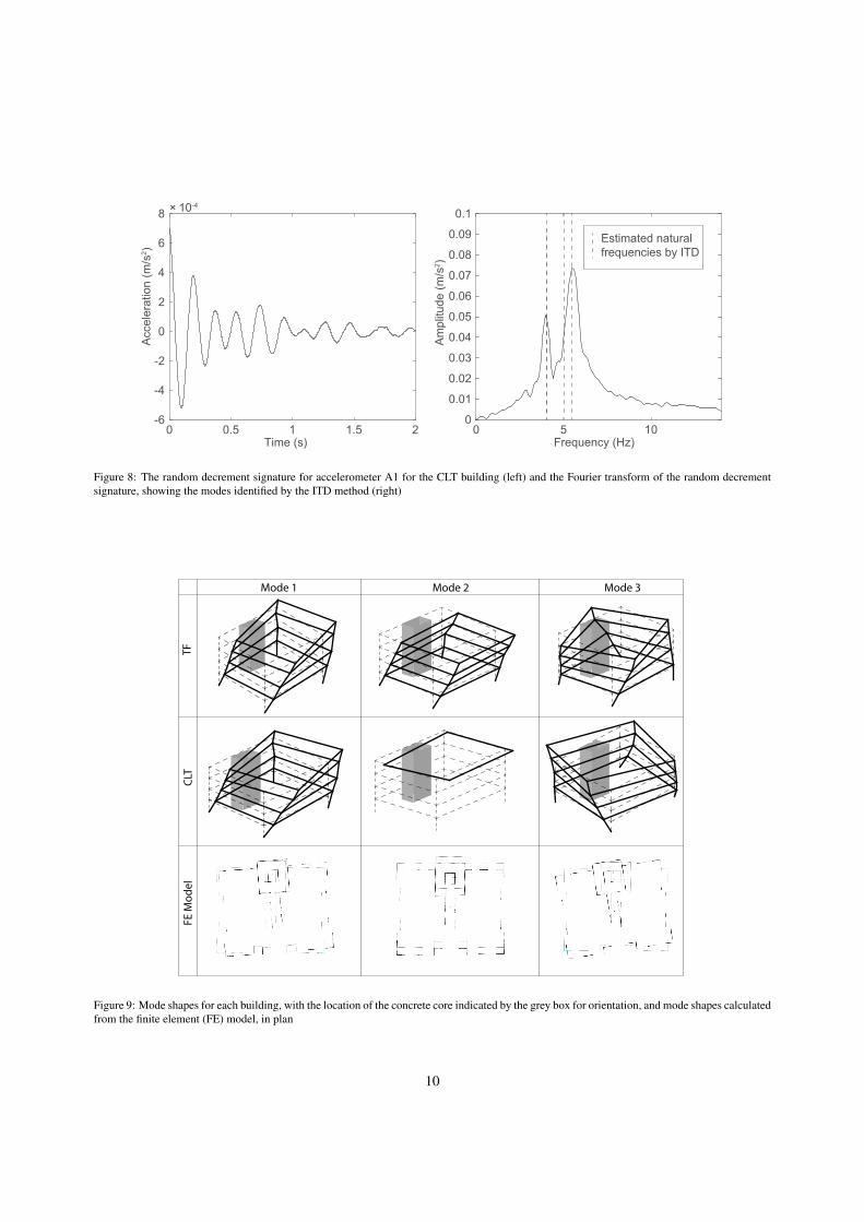
An example of the steps in the process used to extractthe modal properties is shown in Figures 7 and 8. A10-second segment of the 30-minute time-history of ac-celeration is shown in Figure 7, in which can be seen theperiodicity in the response. The periodicity is broughtout much more clearly by the averaging process of therandom decrement method, as can be seen in the ran-dom decrement signature in Figure 8.
In the frequency domain, the peaks corresponding totwo modes of vibration are evident. The ITD methoduses this random decrement signature along with theother 9, which have been generated from the other ac-celerometers, using the same triggering times. Super-imposed on the frequency spectrum in Figure 8, it canbe seen that the ITD method identifies the two modescorresponding to clear peaks on this spectrum, and an-other, which may be more clearly seen on the spectrumfrom another accelerometer.
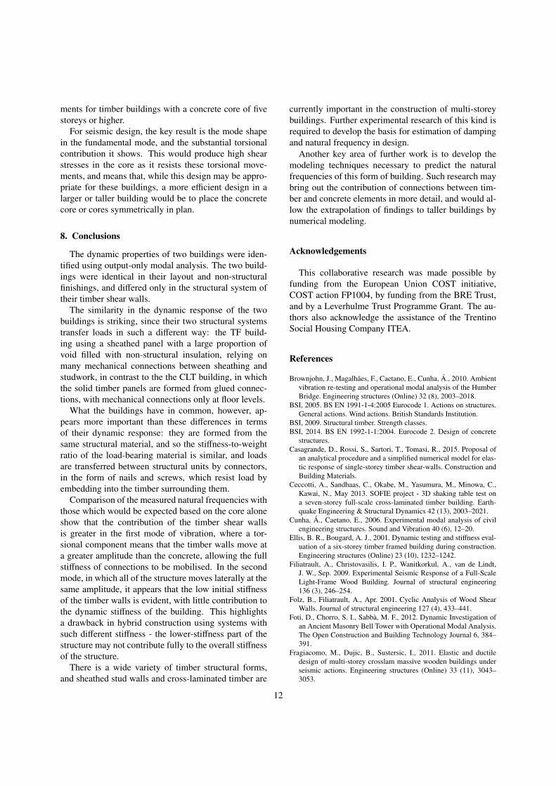
Three modes of vibration were identified for eachbuilding: two with predominantly lateral movement andone of torsional movement in plan. The mode shapesare shown in Figure 9, along with those calculated byfinite element analysis. In one lateral mode, the con-crete core is in the centre of the building in the directionof movement, while in the other, the core is off-centre.It is evident that the concrete core represents a partic-ularly stiff part of the structure, since the mode shapewith the core off-centre includes a substantial rotationaround the core, with the greatest movement at the edge
7

Multiplier for Standard Deviation0. 5 1 1. 5 2 2. 5
Nat
ural
Freq
uenc
y (H
z)
3.8
4
4.2
4.4
Multiplier for Standard Deviation0. 5 1 1. 5 2 2. 5
Dam
ping
(%)
0
10
20
Multiplier for Standard Deviation0. 5 1 1. 5 2 2. 5M
odal
Con
fiden
ceFa
ctor
0
1
2
3
Multiplier for Standard Deviation0. 5 1 1. 5 2 2. 5
Num
ber o
fAv
erag
es
0
2000
4000
6000
Chosen value
Figure 5: Study of the sensitivity of modal parameters to the chosen random decrement trigger level
3.22
2.00
4.59
0.39 0.74
5.59
1.89 1.42 1.89N
0.20
Figure 6: Layout of structural walls in the concrete core, with all dimensions in metres, and of the walls in the finite element model
8
1000 1001 1002 1003 1004 1005 1006 1007 1008 1009 1010
Acc
eler
atio
n (m
/s2 )
×10-3
-1.5
-1
-0.5
0
0.5
1
1.5
Time (s)
Figure 7: A 10-second segment of the time-history of accelerationrecorded by accelerometer A1 for the CLT building
of the building opposite the core, and the least at thecore itself.
The damping ratios and natural frequencies may becalculated separately from the results of each test, andso there is a range of natural frequency and damping es-timates for each mode. The first mode was identifiedusing accelerometer A2 as the trigger channel, and thefollowing two modes using accelerometer A1. This wasthe same for the analysis of each building, with the ex-ception of the second mode in the CLT building, whichwas difficult to identify due to its proximity to the thirdmode. It was found that using accelerometer A5 in test1 as the trigger channel brought out the properties of thismode. Since this accelerometer location was not presentin the other tests, it was only possible to draw a partialmode shape for this mode, as can be seen in Figure 9.
The reliability of the results for each mode from eachtest was assessed by calculating a modal confidence fac-tor (MCF) (He and Fu, 2001), by using the same datawith a time delay of 0.1 s to recalculate the residualfor that mode, allowing for the exponential decay in itsmagnitude. For a true mode, the magnitude of the ratioof the two residuals should be close to unity. This ratiois the MCF. For the TF building, in the case of the fun-damental mode, it was possible to use the first four tests,whereas for modes two and three, only the first two testswere suitably reliable.
The order of the modes is the same in each building:the two lowest-frequency modes consist predominantlyof lateral movement, and the next one predominantlyrotation. Table 5 shows the estimated modal propertiesusing the ITD method for each building. The frequen-cies and damping ratios for the first two modes of vibra-tion were very similar, while the TF building exhibiteda higher frequency in the third, torsional, mode.
The significance of these results in terms of wind-induced vibration can be put into context based on a
calculation using Eurocode 1 (BSI, 2005). Accordingto this standard, the peak acceleration correspondingto a 1-year return period storm may be calculated, andthis may be compared with criteria for human comfortgiven in (ISO, 2007). Based on the measured naturalfrequency and damping ratios, these buildings comfort-ably meet these criteria, with a peak acceleration of0.024 m/s2, well below the limit of 0.082 m/s2 at thisfrequency. In Figure 10, the calculation has been ex-trapolated, with the natural frequency of the buildingassumed to be inversely proportional to the square of theheight, as for a vertical cantilever with constant bendingstiffness. The similarity in the properties of the funda-mental mode in each building means that this calcula-tion applies equally well to each timber structural sys-tem, and can be considered a statement about timberstructural systems with a concrete core in general. Fig-ure 10 shows that, using these structural properties, thelimit for human comfort is quickly exceeded for even afew metres extra height over the 15.6 m of these build-ings.
7. Discussion
The principal effect of the concrete core on the globalresponse of the buildings is that it forms the stiffest partof the structure, and since it is asymmetrically located, itcreates torsion in one of the modes of vibration. Figure9 shows that, in Mode 1 for each building, the off-centreconcrete core causes a torsional element to this predom-inantly lateral mode shape. In Mode 2, for which thebuilding is symmetrical about the core, the mode shapeis one of pure lateral sway.
Comparing the measured natural frequencies withthose calculated using the core alone, it appears thatthe contribution of the timber shear walls is differentin each of the lateral modes of vibration. In the firstmode, a combination of lateral movement in the east-west direction and torsion, the stiffness of the core alonewould suggest a natural frequency of 2.4 Hz, accordingto the calculation in Section 5. The real measured fre-quency of around 4.1 Hz therefore appears to include asubstantial contribution from the timber walls, which isconsistent with the substantial movement of the timberwalls seen in the mode shape. In the second mode, forlateral movement in the north-south direction, the corealone was expected to give a natural frequency of 4.3Hz. The measured natural frequency of around 4.9Hzis therefore only slightly higher. In this mode, the tim-ber walls may only deform as far as the core, and so itappears they do not develop sufficient stiffness at that
9
Frequency (Hz)0 5 10
Am
plitu
de (m
/s2 )
0
0.01
0.02
0.03
0.04
0.05
0.06
0.07
0.08
0.09
0.1
Estimated naturalfrequencies by ITD
0 0.5 1 1.5 2
Acc
eler
atio
n (m
/s2 )
× 10-4
-6
-4
-2
0
2
4
6
8
Time (s)
Figure 8: The random decrement signature for accelerometer A1 for the CLT building (left) and the Fourier transform of the random decrementsignature, showing the modes identified by the ITD method (right)
Mode 1 Mode 2 Mode 3
TFCL
TFE
Mod
el
Figure 9: Mode shapes for each building, with the location of the concrete core indicated by the grey box for orientation, and mode shapes calculatedfrom the finite element (FE) model, in plan
10

Table 5: Ranges of natural frequency and damping ratio for each building, and the range of root mean square (RMS) magnitude of acceleration,measured at the south east corner of the fourth floor, at which the parameters were measured
Mode Natural Frequency Damping Ratio RMS(Hz) (%) (mm/s2)
TF Building1 4.10-4.16 5.8-6.6 5.1-8.82 4.87-4.97 7.3-8.7 5.1-8.83 6.29-6.34 4.6-4.7 5.1-8.8
CLT Building1 4.03-4.08 4.9-6.9 2.5-10.22 4.80-4.99 6.5-8.3 2.5-10.23 5.51-5.63 4.7-7.0 2.5-10.2
Building Height (m)10 20 30 40 50
1-ye
ar R
etur
n Pe
riod
Peak
Acc
eler
atio
n (m
/s2 )
0
0.05
0.1
0.15
0.2
0.25
Response
for 4
.9% d
ampin
g
Response
for 6
.9% damping
ISO 10137:2007 limit
Figure 10: Extrapolating the calculation of peak acceleration for ataller building with the same structural system - this applies to eitherthe CLT or TF building
amplitude to make a substantial contribution to the nat-ural frequency. With the timber walls included with arepresentative elastic modulus, the mode shapes givenby the finite element model show good agreement withthose measured experimentally, as shown in Figure 9.
The similarity in the measured properties between thetwo buildings is notable. The solid timber panels of theCLT building, formed by stiff glue lines, might be ex-pected to be more stiff in isolation than the sheathedstud walls of the TF building, with their more flexiblenailed connections. In the complete structural system,however, there are various features described in Sec-tion 3 which may make the CLT building less stiff. TheTimber frame building has a direct concrete-to-concreteconnection from the wall to the floor, while the CLT re-lies on a screwed connection from the timber floor toa glulam beam loaded perpendicular to grain, and thenbolted to the core - since the core is a particularly stiffelement in the building, this may be expected to be asubstantial difference It may also be that the insulationfilling the voids in the TF panels causes them, underlight wind loads, to behave as solid panels, and there-fore provide a stiffness closer to that of the CLT panels.
The significant difference between the two buildingsis in the frequency of the third mode of vibration. Thismode is characterised by rotation of the building in plan,and it is possible that the greater mass of the walls in theCLT building, located further from the centre of rota-tion, is responsible for the lower frequency of this modein that building.
The theoretical calculation of the response of thesebuildings to higher wind loads, and the response of tallerbuildings with the same system, shows the potential forwind-induced vibration to be a key design criterion inbuildings of this form. These measurements representto the authors’ knowledge, the only damping measure-
11
ments for timber buildings with a concrete core of fivestoreys or higher.
For seismic design, the key result is the mode shapein the fundamental mode, and the substantial torsionalcontribution it shows. This would produce high shearstresses in the core as it resists these torsional move-ments, and means that, while this design may be appro-priate for these buildings, a more efficient design in alarger or taller building would be to place the concretecore or cores symmetrically in plan.
8. Conclusions
The dynamic properties of two buildings were iden-tified using output-only modal analysis. The two build-ings were identical in their layout and non-structuralfinishings, and differed only in the structural system oftheir timber shear walls.
The similarity in the dynamic response of the twobuildings is striking, since their two structural systemstransfer loads in such a different way: the TF build-ing using a sheathed panel with a large proportion ofvoid filled with non-structural insulation, relying onmany mechanical connections between sheathing andstudwork, in contrast to the the CLT building, in whichthe solid timber panels are formed from glued connec-tions, with mechanical connections only at floor levels.
What the buildings have in common, however, ap-pears more important than these differences in termsof their dynamic response: they are formed from thesame structural material, and so the stiffness-to-weightratio of the load-bearing material is similar, and loadsare transferred between structural units by connectors,in the form of nails and screws, which resist load byembedding into the timber surrounding them.
Comparison of the measured natural frequencies withthose which would be expected based on the core aloneshow that the contribution of the timber shear wallsis greater in the first mode of vibration, where a tor-sional component means that the timber walls move ata greater amplitude than the concrete, allowing the fullstiffness of connections to be mobilised. In the secondmode, in which all of the structure moves laterally at thesame amplitude, it appears that the low initial stiffnessof the timber walls is evident, with little contribution tothe dynamic stiffness of the building. This highlightsa drawback in hybrid construction using systems withsuch different stiffness - the lower-stiffness part of thestructure may not contribute fully to the overall stiffnessof the structure.
There is a wide variety of timber structural forms,and sheathed stud walls and cross-laminated timber are
currently important in the construction of multi-storeybuildings. Further experimental research of this kind isrequired to develop the basis for estimation of dampingand natural frequency in design.
Another key area of further work is to develop themodeling techniques necessary to predict the naturalfrequencies of this form of building. Such research maybring out the contribution of connections between tim-ber and concrete elements in more detail, and would al-low the extrapolation of findings to taller buildings bynumerical modeling.
Acknowledgements
This collaborative research was made possible byfunding from the European Union COST initiative,COST action FP1004, by funding from the BRE Trust,and by a Leverhulme Trust Programme Grant. The au-thors also acknowledge the assistance of the TrentinoSocial Housing Company ITEA.
References
Brownjohn, J., Magalhaes, F., Caetano, E., Cunha, A., 2010. Ambientvibration re-testing and operational modal analysis of the HumberBridge. Engineering structures (Online) 32 (8), 2003–2018.
BSI, 2005. BS EN 1991-1-4:2005 Eurocode 1. Actions on structures.General actions. Wind actions. British Standards Institution.
BSI, 2009. Structural timber. Strength classes.BSI, 2014. BS EN 1992-1-1:2004. Eurocode 2. Design of concrete
structures.Casagrande, D., Rossi, S., Sartori, T., Tomasi, R., 2015. Proposal of
an analytical procedure and a simplified numerical model for elas-tic response of single-storey timber shear-walls. Construction andBuilding Materials.
Ceccotti, A., Sandhaas, C., Okabe, M., Yasumura, M., Minowa, C.,Kawai, N., May 2013. SOFIE project - 3D shaking table test ona seven-storey full-scale cross-laminated timber building. Earth-quake Engineering & Structural Dynamics 42 (13), 2003–2021.
Cunha, A., Caetano, E., 2006. Experimental modal analysis of civilengineering structures. Sound and Vibration 40 (6), 12–20.
Ellis, B. R., Bougard, A. J., 2001. Dynamic testing and stiffness eval-uation of a six-storey timber framed building during construction.Engineering structures (Online) 23 (10), 1232–1242.
Filiatrault, A., Christovasilis, I. P., Wanitkorkul, A., van de Lindt,J. W., Sep. 2009. Experimental Seismic Response of a Full-ScaleLight-Frame Wood Building. Journal of structural engineering136 (3), 246–254.
Folz, B., Filiatrault, A., Apr. 2001. Cyclic Analysis of Wood ShearWalls. Journal of structural engineering 127 (4), 433–441.
Foti, D., Chorro, S. I., Sabba, M. F., 2012. Dynamic Investigation ofan Ancient Masonry Bell Tower with Operational Modal Analysis.The Open Construction and Building Technology Journal 6, 384–391.
Fragiacomo, M., Dujic, B., Sustersic, I., 2011. Elastic and ductiledesign of multi-storey crosslam massive wooden buildings underseismic actions. Engineering structures (Online) 33 (11), 3043–3053.
12
Gavric, I., Fragiacomo, M., Ceccotti, A., 2015. Cyclic behaviour oftypical metal connectors for cross-laminated (CLT) structures. Ma-terials and Structures 48 (6), 1841–1857.
Gsell, D., Feltrin, G., Schubert, S., Steiger, R., Motavalli, M., Jan.2007. Cross-Laminated Timber Plates: Evaluation and Verificationof Homogenized Elastic Properties. Journal of structural engineer-ing 133 (1), 132–138.
H Cole, J. R., 1968. On-the-line analysis of random vibrations. In: 9thStructural Dynamics and Materials Conference. American Instituteof Aeronautics and Astronautics.
He, J., Fu, Z.-F., 2001. Modal Analysis. Butterworth-Heinemann, Ox-ford.
He, M., Lam, F., Foschi, R. O., Aug. 2001. Modeling Three-Dimensional Timber Light-Frame Buildings. Journal of structuralengineering 127 (8), 901–913.
ISO, 2007. Bases for design of structures - Serviceability of build-ings and walkways against vibrations. International Organizationfor Standardization.
Judd, J. P., Fonseca, F. S., Feb. 2005. Analytical Model for Sheathing-to-Framing Connections in Wood Shear Walls and Diaphragms.Journal of structural engineering 131 (2), 345–352.
Magalhaes, F., Caetano, E., Cunha, A., Flamand, O., Grillaud, G.,2012. Ambient and free vibration tests of the Millau Viaduct: Eval-uation of alternative processing strategies. Engineering structures(Online) 45 (0), 372–384.
Reynolds, T., Harris, R., Chang, W.-S., Bregulla, J., Bawcombe, J.,2015. Ambient vibration tests of a cross-laminated timber building.Proceedings of the ICE - Construction Materials.
Rodrigues, J., Brincker, R., 2005. Application of the random decre-ment technique in operational modal analysis. In: 1st Int. Opera-tional Modal Analysis Conf. (IOMAC). Aalborg Universitet, Aal-borg, Denmark.
Tomasi, R., Sartori, T., Casagrande, D., Piazza, M., Dec. 2014.Shaking table testing of a full scale prefabricated three-storytimber framed building. Journal of Earthquake Engineering,141217131810008.
van de Lindt, J. W., Pryor, S. E., Pei, S., 2011. Shake table testing of afull-scale seven-story steel-wood apartment building. Engineeringstructures (Online) 33 (3), 757–766.
Vessby, J., Enquist, B., Petersson, H., Alsmarker, T., 2009. Experi-mental study of cross-laminated timber wall panels. Holz als Roh-und Werkstoff 67 (2), 211–218.
13