comparison of numerical investigation on airfoil and flat ... · pdf fileintroduction air...
TRANSCRIPT

Procedia Engineering 41 ( 2012 ) 1761 – 1768
1877-7058 © 2012 Published by Elsevier Ltd.doi: 10.1016/j.proeng.2012.07.380
International Symposium on Robotics and Intelligent Sensors 2012 (IRIS 2012) Comparison of Numerical Investigation on Airfoil and Flat Louvers
on the Air Duct Intake Mohd Hafiz Mohd Noha, Helmi Rashidb, Ahmad Hussein Abdul Hamidb, Muhammad Faisal
Iskandarb aFaculty of Mechanical Engineering, UiTM Shah Alam, 40450 Shah Alam, Malaysi
aFaculty of Mechanical Engineering, UiTM Shah Alam, 40450 Shah Alam, Malaysia
Abstract
Louver’s design are play important role in designing an air intake system. On a gas turbine power plant application, this louver will redirect the air flow path into the compressor and for the system’s internal cooling. However, the shape and design of the louvers will influence the performance of a gas turbine. Disturbed airflow across the louvers may cause pressure drop of the intake air, which leads to reduction of the turbine work output. In this research, the effect of varying the angle of attack on the airfoil and flat shape louvers are investigated. Airfoil louvers were based on the symmetrical 4-digit NACA airfoil shape, with its maximum thickness of 10mm. CFD analysis was conducted by using the built-in Solidworks Flow Simulation to visualize the air flow behavior across the louvers at the angles of attack of 25o, 35 o and 45 o. The results revealed that the pressure drop is more prevalent in flat louvers as compared to airfoil louvers. Furthermore, the pressure of the airflow reduced more with higher angle of attack due to vortex formation. © 2012 The Authors. Published by Elsevier Ltd. Selection and/or peer-review under responsibility of the Centre of Humanoid Robots and Bio-Sensor (HuRoBs), Faculty of Mechanical Engineering, Universiti Teknologi MARA. Keywords: Air intake system, flat louvers, airfoil louvers, pressure drop, angle of attack
1. Introduction
Air intake system is essential for a gas turbine operation. Air suctioned into the system is used as oxidizing agent for engine combustion and as a cooling medium for turbomachineries component of a gas turbine. Poor air intake system will result in poor overall performance of the gas turbine. For that reason, it is important to ensure that the airflow in the system to be “as smooth as” possible. An air intake system may consist of weather hood with an array of louvers, multiple stages of filter and inlet duct with silencer. Ambient air with atmospheric pressure is first entering the weather hood, where it bypasses the filters before travelling further downstream into the inlet duct into the compressor. The air may experience the reduction of air pressure, due to the disturbances and friction present throughout the intake system. Large pressure drop across the system will increase the engine’s fuel consumption and reduce the turbine work output due to low air inlet mass flow and engine’s combustion temperature.
Weather hood is installed upstream of the air inlet system, where it function to deflect large particles including rain and snow droplets from the inlet air stream, and at the same time, directing ambient air into the system. It is built by an array of 2-dimensional flat louvers pointed upward at an angle with relative to the flow direction. An efficient weather hood should be able to remove large particles from the flow stream and at the same time limit the large scale of pressure loss in the airflow across its louvers. As compression ratio is fixed for a gas turbine compressor, therefore low air pressure at the compressor inlet will result in relatively low air pressure into the combustion chamber which consequently will produce low work output.
Common louvers installed in the weather hood are of flat geometry. Although some ventilation systems for building have employed airfoil louvers for an aerodynamic purpose, weather hood on gas turbine has not yet follow the same method. Theoretically, airfoil louvers should be able to provide smoother airflow due to its streamlined geometry, recording lower pressure losses and as a result producing more efficient air ventilation in the gas turbine air intake system. This research investigates the effect of airfoil and flat louvers and angle of attack onto the pressure drop across weather hood. A
Available online at www.sciencedirect.com
Open access under CC BY-NC-ND license.
Open access under CC BY-NC-ND license.

1762 Mohd Hafi z Mohd Noh et al. / Procedia Engineering 41 ( 2012 ) 1761 – 1768
sub-scaled weather hood model with three different louvers arrangement was developed using commercial design software Solidworks. Louvers with angle of attack of 25o, 35o and 45o was designed for airfoil geometry and CFD analysis was conducted by the built-in Solidworks Flow Simulation software with airflow velocity was set as the inlet boundary condition and static pressure for the outlet. The behavior of airflow passing through the louvers were analyzed and tabulated to search for the optimum louvers’ angle of attack and geometry that resulted in less pressure drop throughout the weather hood model. This research will only focus on the pressure drop across weather hood model with NACA 4-digit symmetrical airfoil louvers arranged with angle of attack of 25o, 35o and 45o, whereby the flow velocity and pressure inside the weather hood model were being the major consideration. Generally, louvers for air ventilation of building have been studied consistently, but very little effort has been put on gas turbine weather hood.
2. Literature Review
An air intake system is a section in gas turbine that draws ambient air and route it into the compressor. Air is an essential consumables for a gas turbine operation, thus air ingested into the device must be of high quality, clean and have sufficient pressure. To meet these criteria, the air intake system is often equipped with components including weather hood, a series of filters, ductwork, and silencer. All of the components must be designed with as little flow disruption as possible to the air entering the system because large disruption on the airflow will result in large pressure drop, consequently reducing the combustion temperature hence increasing the engine’s fuel consumption and producing less work from the turbine [14]. Air first enter the weather hood at local pressure and velocity, and continue downstream to multiple stages of filters which normally includes insect screen, anti-icing, inertial separator, pre-filter, and high efficiency filter. The airflow continues into the ductwork which convoys the air into the gas turbine compressor. In each of these stages pressure drop occurs due to formation of vortices, friction and turbulence airflow. Numerous studies have been conducted to investigate the pressure drop across these components.
Khorshand et al. [7] investigates the flow pattern and pressure loss of Khoramshar Power Plant v94.2.5 Gas Turbine air intake units. Its aim is to improve the pressure loss and flow characteristics of the gas turbine compressor inlet. The components involved in the study are weather hood, filter house, bending duct and silencers, and transition piece and compressor inlet cone. The model used in the analysis for this research is as shown in figure 1 (b). A 3-dimensional simulation of flow past components in air intake system was conducted by using commercial numerical CFD software, FLUENT. Simulation on weather hood shows vortex formation in louvered part of the weather hood, where caused the flow velocity to increase, reducing the pressure of air pass through the weather hood. Although pressure loss in intake system is more significant across filter and ductwork, the inlet louvers of weather hood also record a considerable amount pressure differential. He also found that vortex formed in the angled louvers of weather hood as in figure 1, which contribute to flow pressure loss.
(a) (b)
Fig. 1. (a)Velocity vector of airflow inside weather hood louvers [7] and (b) Air intake system of Khoramshar Power Plant A V94.2.5 Gas Turbine [7]
Nevertheless, Nakanishi et al. [6] conducted a study on the behavior of airflow passing through flat louvers and analyzed the generation mechanism of pressure loss. Three sets of louver models were used in the experiment; planar louver board of 45o, 35o, and 25o. The objective of the research is to obtain the design direction for louver shape that minimizes pressure loss when air passes through louvers while satisfying its necessary function. Three methods were used. Wind tunnel measurement was conducted on the sample models to get the pressure loss characteristics as a parameter of the louver angle.
1763 Mohd Hafi z Mohd Noh et al. / Procedia Engineering 41 ( 2012 ) 1761 – 1768
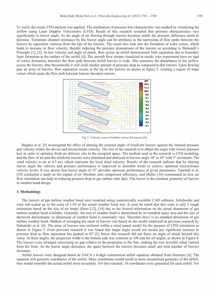
To verify the result, CFD analysis was applied. The mechanism of pressure loss characteristic was studied by visualizing the airflow using Laser Doppler Velocimetry (LVD). Result of this research revealed that pressure characteristics vary significantly to louver angle. As the angle of air flowing through louvers becomes small, the pressure difference tends to decrease. Variations channel resistance by the louver angle can be attributes to the narrowing of flow paths between the louvers by separation vortexes from the tips of the louvers. The result also look into the formation of wake vortex, which leads to increase in flow velocity, thereby reducing the pressure downstream of the louvers as according to Bernoulli’s Principle [1], [2]. At low velocity and angle of attack, flow across an airfoil demonstrates little separation due to boundary layer formation at the surface of the airfoil [4]. The smooth flow stream visualized in smoke wire experiment have no sign of vortex formation, therefore the flow path between airfoil louvers is wide. This minimize the disturbance to the airflow across the louvers, thus theoretically it will yield smaller amount of pressure drop as compared to flat louvers. Upon flowing past an array of louvers, flow separation occurs at the tip of the louvers as shown in figure 2, creating a region of wake vortex which cause the flow path between louvers becomes narrow.
Fig. 2. Velocity vector of airflow across flat louvers [6]
Hughes et al. [5] investigated the effect of altering the external angle of windvent louvers against the internal pressure and velocity within the device and microclimate velocity. The aim of the research is to obtain the angle with lowest pressure loss in order to optimize fresh air delivery rate to the occupied space. The method used in the research is CFD modeling, and the flow of air past the windvent louvers were simulated and analyzed at louvers angle 10o to 45o with 5o increment. The wind velocity is set at 4.5 m/s which represent the local wind velocity. Results of the research indicate that by altering louver angle the velocity and pressure performance is improved to desirable levels to achieve optimum microclimate velocity levels. It was shown that louver angle of 35o provides optimum performance at given parameters. Turnbull et al. [10] conducted a study on the impact of air filtration onto compressor efficiency, and Muller [16] commented on how air flow simulation can help in reducing pressure drop in gas turbine inlet duct. Flat louver is the common geometry of louvers in weather hood design.
3. Methodology
The louvers of gas turbine weather hood were modeled using commercially available CAD software, Solidworks and were sub-scaled up to the scale of 1:50 of the actual weather hood size. It must be noted that this scale is only a rough estimation based on the size of air intake filters [12], [14] due to the limited information on the actual dimension of gas turbine weather hood available. Generally, the size of weather hood is determined by its installed space area and the size of ductwork downstream, so dimension of weather hood is commonly vary. Therefore there is no standard dimension of gas turbine weather hood. Method of arranging the stack of louvers was based on the model employed in previous research by Nakanishi et al. [6]. The array of louvers was enclosed within a wind tunnel model for the purpose of CFD simulation as shown in Figure 3. From previous research it was found that larger angle would not record any significant increase in pressure drop as flow separation has peaked at 45o [5], hence this research did not focus on angle of attack beyond this value. At these angles, the projection width to the bottom side was common at 100 mm for all angles, as shown in Figure 4. The louvers were arranged concerning no gap relative to the projection to the fore, making the rear invisible when viewed from the front. As the louver angle decreases, the space between the louvers becomes small and total number of louvers increases.
Airfoil louvers were designed based on NACA’s 4-digit symmetrical airfoil equation obtained from literature [4]. The equation will generate coordinates of the airfoil. More coordinates would result in more streamlined geometry of the airfoil, thus would resemble the actual airfoil more accurately. For this research, 10 coordinates were generated for each airfoil. For

1764 Mohd Hafi z Mohd Noh et al. / Procedia Engineering 41 ( 2012 ) 1761 – 1768
prior calculation, the parameters were taken the same as flat louvers of the similar angle in order to make a reliable comparison where the value of chord length for 25o flat louvers is 115 mm and its maximum thickness is 10 mm. As with the flat louvers, airfoil louvers were modeled at three angles of attack, 25o, 35o, and 45o, all inclined upward relative to the flow stream. The projection width of the bottom side was common at 100 mm. Method of configuration of airfoil louvers is the same as flat louvers, as shown in figure 3(a). On the other hand, flat louvers model were designed based on the planar louver board used in the research by Nakanishi et al. [6]. Three types of model were used with different angles of attack, similar as airfoil louvers. The louvers were inclined upwards relative to the flow stream, so that air flow directed upward upon contact with the louvers. This is a common configuration in weather hood design, intended to deflect rain and large particles from entering the air intake system of the gas turbine.
(a) (b)
Fig. 3 The arrangement of the respective louvers (a) Airfoils louver models (b) Flat louver models
The number of louvers in a stack for airfoil louvers model was identical to create uniform face area for the inlet of airflow into the weather hood. Difference in face area would result in difference of inlet pressure and velocity condition. The arranged louvers were enclosed inside a box-shaped geometry representing weather hood model for CFD simulation. Side view of sectioned arranged airfoil louvers are as in figure 4(a) and 4(b).
(a) (b)
Fig. 4 Complete computational model (a) 250 Airfoils louver models (b) 250 Flat louver models
The side wall thickness was designed at 15 mm. Lid of 5 mm thickness was created at the entrance and exit of the weather hood model, in order to specify the boundary condition in Solidworks Flow Simulation. To increase the accuracy of the simulation analysis, the lowest louver was designed attached to the floor of the weather hood so that all of the air entering the system flows past through the stack of louvers. Flow analysis of the model was conducted on Solidworks Flow Simulation, a built-in CFD interface in Solidworks. The turbulent nature of the flow is modeled by the standard k-ε model

1765 Mohd Hafi z Mohd Noh et al. / Procedia Engineering 41 ( 2012 ) 1761 – 1768
as in previous researches [5], [6], [7], where k refers to turbulent kinetic energy and the term ‘ε’ refers to turbulent energy dissipation rate [7]. The governing equations used were 2-dimensional Navier-Stokes equation and continuity equation [1]. Since the flow is less than the compressibility Mach number of 0.3, the effect of flow compressibility was not considered hence the airflow in this research was treated as incompressible flow [1]. The whole structure of weather hood model was taken as the computational domain for CFD simulation. Boundary conditions were specified at the front and rear surface of the weather hood model with respect to flow direction. Flow velocity of 5 m/s was set as the inlet boundary condition while static pressure was set as the outlet boundary condition. The velocity set was the average offshore wind velocity in east coast Malaysia, the region where many gas turbines are in operation for oil and gas industry [19]. The overall set up of boundary condition for the weather hood model is as shown in figure 5.
Fig. 5 Sectioned view on set up of boundary conditions at weather hood model with 25o airfoil louvers
The points were plotted within 200 mm of the louvers, which is estimation that the flow within this region characterized the flow between the narrow channels between louvers. Pressure at upstream and downstream of the louvers was obtained by averaging all four points at respective location. Difference between pressure at points upstream and downstream of the louvers cannot be considered as the pressure drop of the overall model, because within this region the flow might not yet be stabilized. In some louvers arrangement the wake due to separation can be very significant, and may take longer time to reattach. This will result in unstable flow properties, and the measurement might not picture the actual properties of the flow. Because there is no experimental work of the same scale was conducted, validation of results for this research relies solely on previous reliable works. The method of which CFD simulation was carried out in this research followed closely to the works by Nakanishi et al. [6], Hughes et al. [5], and Khorshand et al. [7] by using the same k-ε turbulence model and comparable boundary conditions and assumptions. The scale of louvers model used in this research however is different from the stated works, thus the results obtained were ineligible for direct comparison. Therefore validation of results was made by comparison of trend in pressure drop and velocity profile throughout the louvers with the findings of previous works as mentioned.
4. Result and Discussion
The aim of the CFD simulation was mainly to investigate the pattern of air flowing across louvers of gas turbine weather hood in different louvers angle. Pressure drop across the weather hood model was the main consideration in this research, thus discussion will only focus on flow behavior that contributed towards the differential pressure within the calculation domain. Factors that contribute towards the pressure drop within the weather hood model were examined from the visual output of Solidworks Flow Simulation. Table 1 and 2 summarized the results calculated by Solidworks Flow Simulation for pressure at flow inlet and outlet of the weather hood model, pressure difference across the model and the average velocity throughout for angle of 25, 35 and 45o.
The relation between flow velocity and pressure can be deduced from Bernoulli’s Principle and the occurrence of pressure drag of flow around a body which can be applied throughout the narrow region between louvers [1]. If the region around the louvers arrangement is taken as a sub-domain, the flow around them can be considered as external flow. From Bernoulli’s principle for steady, incompressible flow, increase in velocity within a flow region would result in decrease in pressure in the same region [1]. The result shows that increase in louver angle results in larger velocity, and hence greater pressure drop. The results in table 1 also shows that higher louver angle induce higher pressure drop and velocity. This also supported by the work of Nakanishi et. al. [6] and Hughes [5].
Inlet Velocity 5m/s
Outlet Static Pressure

1766 Mohd Hafi z Mohd Noh et al. / Procedia Engineering 41 ( 2012 ) 1761 – 1768
TABLE 1. Results for airfoil louvers
Angle (0) Inlet Pressure (Pa) Outlet Pressure (Pa) ΔP Velocity (m/s)
25 101371.56 101325 46.56 5.63 35 101407.82 101325 82.82 5.93 45 101512.41 101325 187.41 6.58
TABLE 2. Results for flat louvers
Angle (0) Inlet Pressure (Pa) Outlet Pressure (Pa) ΔP Velocity (m/s)
25 101396.62 101325 71.62 5.86 35 101441.51 101325 116.51 6.18 45 101580.23 101325 255.23 6.93
Pressure drop increases with increasing louver angle, producing quite identical percentage of increment relative to 25o
louver model. However pressure drop recorded across all three louver angles in weather hood models were lower as compared to flat louvers due to streamlined airfoil geometry [4]. The streamlined airfoil geometry results in less significant vortex formation between louvers arrangement due to the fact that flow separates in lower magnitude around streamlined body compared to blunt geometry for the same angle of attack [1]. Flow velocity calculated throughout the entire domain also yield similar trend to flat louvers model, where higher angle of attack resulted in higher flow velocity.
(a) (b) (c)
Fig. 6 Velocity counters for airfoil louvers model (a) 250 (b) 350 (c) 450
Figure 6(a), 6(b) and 6(c) shows the velocity counters for different angle of attack for airfoil louvers. Form all the
figures, it can be observed that as increase the louvers angle, the airflow within the narrow region between louvers can be represented by Bernoulli’s principle. Formation of vortex induced by flow separation of the flow current result in increasing velocity through the region, thus decrease in pressure. From the velocity vector, it can be visualized that upon contact with the frontal surface of the louvers, a small region of separated flow at the leading edge is observed, a phenomenon known as flow separation [1], [2], [5]. The separated flow reattaches to the surface downstream, forming a bubble in the region near the leading edge of the louvers known as vortex [1], [2], [5]. As the louver angle increases, flow separation occurs in greater magnitude and the reattachment point moves further downstream, resulting in larger vortex. As shown in figure 6(b) and 6(c), flow separate below the louver for both 35o and 45o model, but it reattach almost immediately at the rear edge of 35o louver, whereas the flow taking longer distance to reattach in 45o louver.

1767 Mohd Hafi z Mohd Noh et al. / Procedia Engineering 41 ( 2012 ) 1761 – 1768
(a) (b) (c)
Fig. 7 Velocity counters for flat louvers model (a) 250 (b) 350 (c) 450
From the velocity vector, it can be concluded that flow velocity increases as the flow path between louvers was narrowed down due to vortex formation. When the louver angle increases, flow separation caused larger vortex thus increasing the pressure difference due to the pressure loss by the increasing velocity. This trend confirms the finding of previous researches on the relation of louver angle with vortex formation and subsequent pressure drop [5], [6]. The relation between flow velocity and pressure can be deduced from Bernoulli’s Principle and the occurrence of pressure drag of flow around a body which can be applied throughout the narrow region between louvers [1]. If the region around the louvers arrangement is taken as a sub-domain, the flow around them can be considered as external flow. From Bernoulli’s principle for steady, incompressible flow, increase in velocity within a flow region would result in decrease in pressure in the same region [1]. Formation of vortex induced by flow separation of the flow current result in increasing velocity through the the region, thus decrease in pressure. A sample of pressure contour for weather hood with 25o airfoil louver was taken for example as in figure 8(a) and 8(b) showing the difference in pressure concentration upstream and downstream of the louvers arrangement. As discussed, pressure drop is significant between air flows upstream and downstream of the louvers arrangement.
(a) (b)
Fig. 8 Pressure counters (a) 250 airfoil louvers model (b) 250 flat louvers model
5. Conclusion
From the result obtained, it was found that higher louver angle induce larger pressure drop across the louvers for both flat and airfoil geometry. This trend has been supported by previous research on similar study. By visualizing the velocity vector of all models, formation of vortex due to flow separation was found to be the cause for pressure drop across the louvers. Larger angle of attack results in higher magnitude of flow separation with increased distance for reattachment point, creating larger vortex below the louver. This vortex narrowed down the flow path between louvers causing increased velocity within that region, reducing the pressure as stated by Bernoulli’s Principle. In the investigation onto louvers geometry, it was found that airfoil louvers induce lower pressure drop than flat louvers due to its streamlined geometry. This

1768 Mohd Hafi z Mohd Noh et al. / Procedia Engineering 41 ( 2012 ) 1761 – 1768
encouraged flow separation point to move further downstream on the louver, creating less significant vortex compared to flat louvers. Beside, the finding also shows that at higher angle the difference become less significant due to the increasing stalling effect of the louver. For airfoil louvers, the flow separation point is tend to move further downstream on the louver, creating less significant vortex compared to flat louvers. This shows that at higher angle the difference become less significant due to the increasing stalling effect of the louver. Several aspects can be introduced into further research with similar scope of study to generate more accurate and reliable result. The experimental study which was not conducted in this research to validate the CFD simulation results is encourage to be done in the future.
Acknowledgment The authors greatly acknowledge the Computer Lab at Faculty of Mechanical Engineering, Universiti Technology
MARA (UiTM), Malaysia for all the facilities and also RMI UiTM for financial support through Dana Kecemerlangan.
References [1] Cengel, Y. A.; M. Cimbala, J.M. (2006). “Fluid mechanics fundamentals and applications”. 1st ed. New York, US; McGraw-Hill. [2] Cengel, Y. A.; Boles, M. A. (2007). “Thermodynamics; An engineering approach”. 6th ed. New York, US; McGraw-Hill.. [3] White, F. M. (2008). “Fluid Mechanics”, 6th ed. New York, US. McGraw-Hill. [4] Houghton, E.; Carpenter, P. W. (2003). “Aerodynamics for engineering student”, 5th ed. New York, US. Elsevier. [5] Hughes, B. R.; Ghani, S. A. A. (2010). “A Numerical Investigation into the Effect of Windvent Louver External Angle on Passive Stack Ventilation
Performance”, The Journal of Building and Environment 45: 1025-1036. [6] Nakanishi, T.; Nakamura, T.; Watanabe, Y.; Handou, K.; and Kiwata, T. (2007).” Investigation of air flow passing through louvers”, Komatsu
Technical Report. Japan. Komatsu Inc. [7] Khorsand, K.; Karimian, S. M.; Varmaziar, M.; and Sarjami, S. (2008). “Investigation of Flow Pattern and Pressure Loss of Av94.2.5 Gas Turbine
Air Intake System Using 3D Numerical Modeling”, Department of Engineering.; Department of Aerospace. Amir Kabir University. Tehran, Iran. [8] Bertolami, U. A.; Hill, D. G. (1993). “Gas turbine inlet air treatment: A new technology”, International Gas Turbine and Aeroengine Congress and
Exposition. The American Society of Mechanical Engineers. New York. [9] Ward, T. A. (2010). “Aerospace propulsion systems”, 1st ed. Singapore. John Wiley & Sons (Asia) [10] Turnbull, G.; Clement, E.; and Ekberg, Tord.; “Gas Turbine Combustion Air Filtration: Its Impact on Compressor Efficiency and Hot End
Component Life”, Position Paper. European Turbine Network A.I.S.B.L [11] Loud, R. L.; Slaterpryce, A. A.; “Gas Turbine Inlet Air Treatment”, New York, US. GE Company. [12] Wilkes, C. (2007)”. Power Plant Layout Planning: Gas Turbine Inlet Air Quality Considerations”, New York. GE Energy. [13] Langston, L. S.; Opdyke, G. (1997). “Introduction to Gas Turbine for Non-Engineers. Global Gas Turbine” News 37. [14] Wilcox, M.; Baldwin, R.; Garcia-Hernandez, A.; and Brun, K. (2010). “Guideline for Gas Turbine Inlet Air Filtration Systems”, Release 1.0. New
York, US. Gas Machinery Research Council. [15] Sutherland, K. (2008). “Gas Turbine Intake Air Filtration. Filtration + Separation”, January-February 2008. [16] Muller, F. (2006). Simulation Helps Reduce Pressure Drop on Gas turbine Inlet Duct by 50%. Texas, US. Mueller Environmental Design Inc. [17] Rolls-Royce Technical Publication Departments. “The Jet Engine”, 5th ed. England. Rolls-Royce Plc. [18] Badran, O. O. (1999). “Gas Turbine Performance Improvements”, Journal of Applied Energy 64: 263-273. Elsevier [19] Khadijah, S.; Zaharim, M.; Razali, A. M.; Zainol, M. S.; Ibrahim, K.; Sopian, K. (2009). “Analyzing the East Coast Malaysia Wind Speed”, Data.
The International Journal of Energy and Environment 2(3): 53-60.