comparison of obstacle avoidance behaviors for a … · comparison of obstacle avoidance behaviors...
TRANSCRIPT
Comparison of Obstacle Avoidance Behaviors for aHumanoid Robot in Real and Simulated Environments
Stephen G. McGill∗, Yida Zhang∗, Larry Vadakedathu∗,Aditya Sreekumar∗, Seung-Joon Yi∗, and Daniel D. Lee∗
Abstract—RoboCup soccer is still host to frequent collisionsbetween robots that lead to unsavory gameplan that is typicallynot allowed in human soccer. In the Standard Platform leaguewhere ultrasonic sensors are employed, these collisions areforbidden, but there is still leniency in the Humanoid League.Additionally, advanced behaviors, such as dribbling, requirerobust obstacle avoidance strategies to keep possession of theball. Challenges in the RoboCup competition seek to demon-strate ways to dribble around static obstacles, but it can behard to replicate conditions for the sake of iteratively tuningrobot behavior. We present a method for evaluating policiesin simulation and on the real robot for obstacle avoidancebehaviors.
Keywords : Obstacle avoidance, robot soccer
I. INTRODUCTION
The RoboCup humanoid soccer competition strives toproduce humanoid robots that will someday be able toplay soccer against the human soccer team that wins theWorld Cup. To accomplish this, rules in the league graduallyresemble more closely those of FIFA. One of the outstand-ing issues, however, is that contact between players is notpenalized much.
In the Standard Platform League, contact is alreadybanned, but in the Humanoid League, inevitably, this le-niency will be removed. It is important to have a frame-work for preventing contact for current Standard Platformteams and for future Humanoid League teams. Teams havealready demonstrated obstacle avoidance and dribbling in theobstacle avoidance challenges extraneous of actual matches.However, this avoidance has not been practically used inreal matches. In order to integrate obstacle avoidance anddribbling into real matches, the obstacle avoidance must beproven to be reliable through extensive testing.
One useful testing platform is simulation, where poli-cies are iterated in simulation, and then evaluated on realhardware. We are striving to have real time solution, whereparticular fail cases on the real hardware can be duplicatedimmediately in simulation and debugging can happen atthe same time on the simulator and the real robot. Thisrequires analysis of the consistency between simulation andreal hardware at a high level.
Previous work in analyzing consistencies between sim-ulation and real environment has been examined primarilyfor motions. If certain sets of parameters yield the same
∗ GRASP Laboratory, University of Pennsylvania, Philadelphia, PA 19104{smcgill3,yida,vlarry}@seas.upenn.edu{adityasr,yiseung,ddlee}@seas.upenn.edu
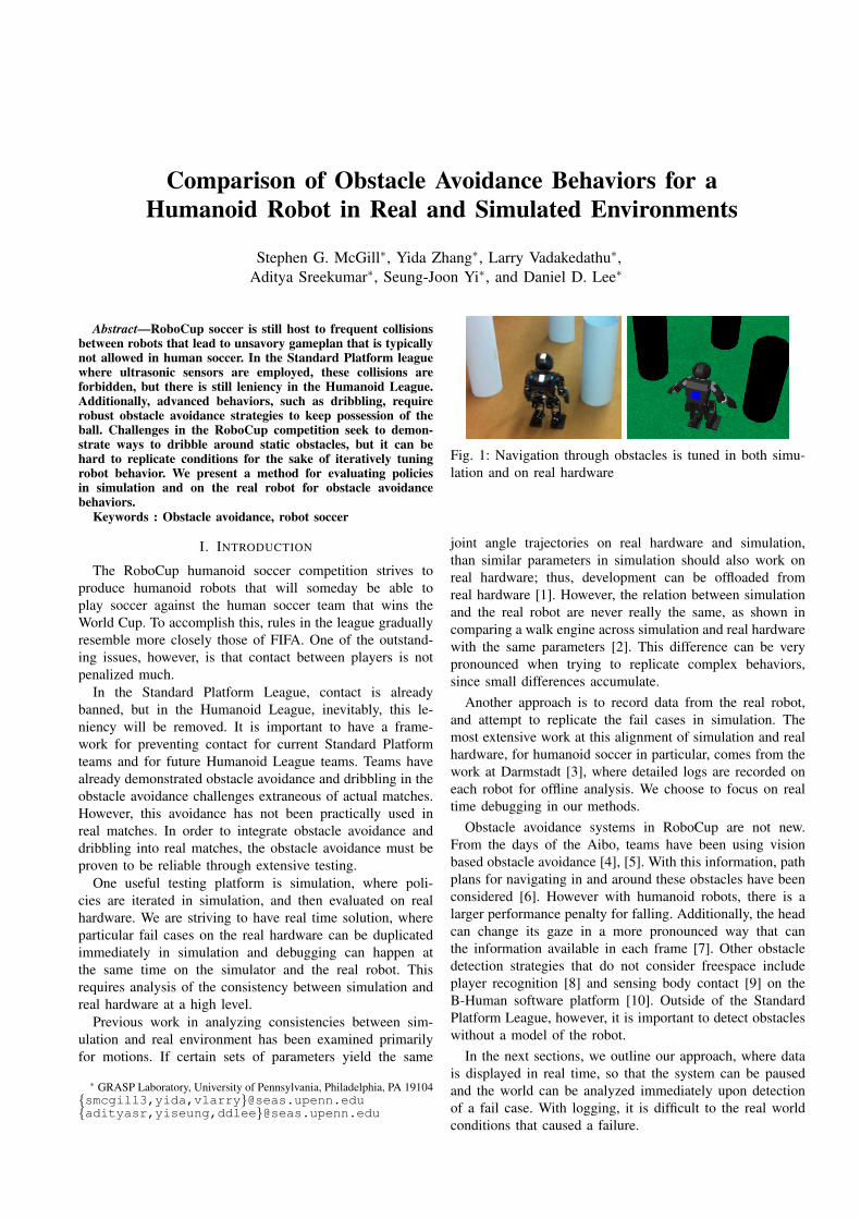
Fig. 1: Navigation through obstacles is tuned in both simu-lation and on real hardware
joint angle trajectories on real hardware and simulation,than similar parameters in simulation should also work onreal hardware; thus, development can be offloaded fromreal hardware [1]. However, the relation between simulationand the real robot are never really the same, as shown incomparing a walk engine across simulation and real hardwarewith the same parameters [2]. This difference can be verypronounced when trying to replicate complex behaviors,since small differences accumulate.
Another approach is to record data from the real robot,and attempt to replicate the fail cases in simulation. Themost extensive work at this alignment of simulation and realhardware, for humanoid soccer in particular, comes from thework at Darmstadt [3], where detailed logs are recorded oneach robot for offline analysis. We choose to focus on realtime debugging in our methods.
Obstacle avoidance systems in RoboCup are not new.From the days of the Aibo, teams have been using visionbased obstacle avoidance [4], [5]. With this information, pathplans for navigating in and around these obstacles have beenconsidered [6]. However with humanoid robots, there is alarger performance penalty for falling. Additionally, the headcan change its gaze in a more pronounced way that canthe information available in each frame [7]. Other obstacledetection strategies that do not consider freespace includeplayer recognition [8] and sensing body contact [9] on theB-Human software platform [10]. Outside of the StandardPlatform League, however, it is important to detect obstacleswithout a model of the robot.
In the next sections, we outline our approach, where datais displayed in real time, so that the system can be pausedand the world can be analyzed immediately upon detectionof a fail case. With logging, it is difficult to the real worldconditions that caused a failure.
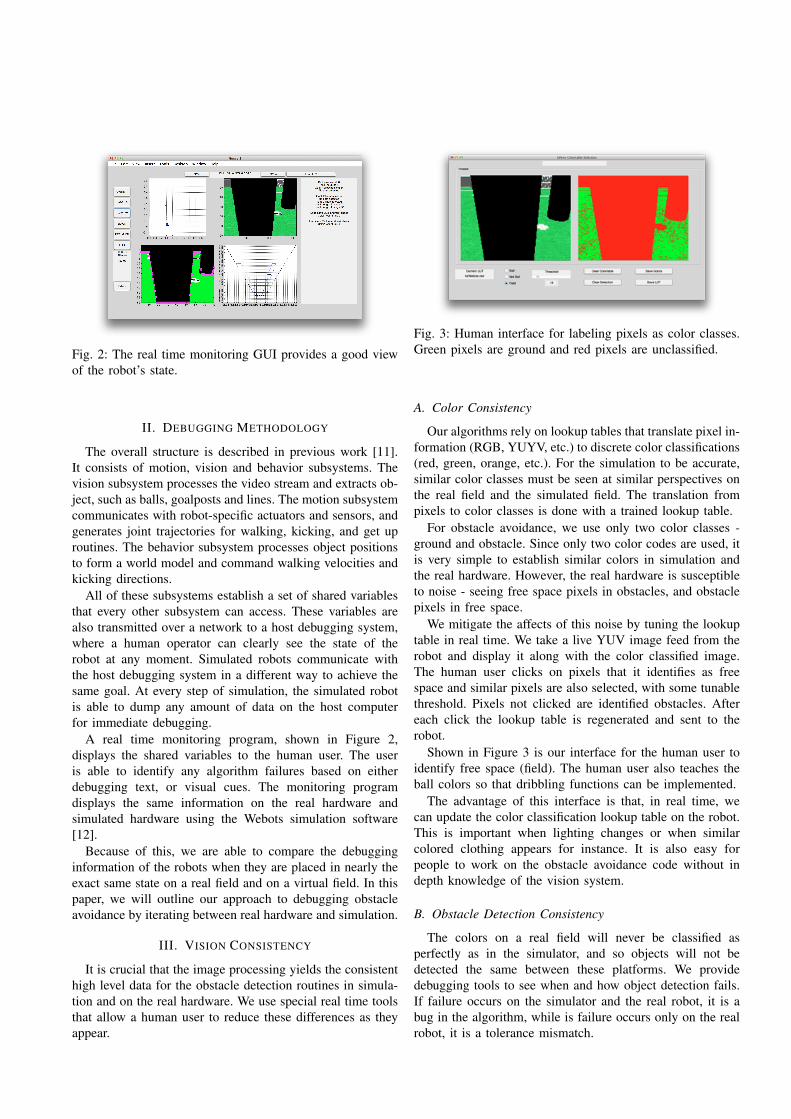
Fig. 2: The real time monitoring GUI provides a good viewof the robot’s state.
II. DEBUGGING METHODOLOGY
The overall structure is described in previous work [11].It consists of motion, vision and behavior subsystems. Thevision subsystem processes the video stream and extracts ob-ject, such as balls, goalposts and lines. The motion subsystemcommunicates with robot-specific actuators and sensors, andgenerates joint trajectories for walking, kicking, and get uproutines. The behavior subsystem processes object positionsto form a world model and command walking velocities andkicking directions.
All of these subsystems establish a set of shared variablesthat every other subsystem can access. These variables arealso transmitted over a network to a host debugging system,where a human operator can clearly see the state of therobot at any moment. Simulated robots communicate withthe host debugging system in a different way to achieve thesame goal. At every step of simulation, the simulated robotis able to dump any amount of data on the host computerfor immediate debugging.
A real time monitoring program, shown in Figure 2,displays the shared variables to the human user. The useris able to identify any algorithm failures based on eitherdebugging text, or visual cues. The monitoring programdisplays the same information on the real hardware andsimulated hardware using the Webots simulation software[12].
Because of this, we are able to compare the debugginginformation of the robots when they are placed in nearly theexact same state on a real field and on a virtual field. In thispaper, we will outline our approach to debugging obstacleavoidance by iterating between real hardware and simulation.
III. VISION CONSISTENCY
It is crucial that the image processing yields the consistenthigh level data for the obstacle detection routines in simula-tion and on the real hardware. We use special real time toolsthat allow a human user to reduce these differences as theyappear.
Fig. 3: Human interface for labeling pixels as color classes.Green pixels are ground and red pixels are unclassified.
A. Color Consistency
Our algorithms rely on lookup tables that translate pixel in-formation (RGB, YUYV, etc.) to discrete color classifications(red, green, orange, etc.). For the simulation to be accurate,similar color classes must be seen at similar perspectives onthe real field and the simulated field. The translation frompixels to color classes is done with a trained lookup table.
For obstacle avoidance, we use only two color classes -ground and obstacle. Since only two color codes are used, itis very simple to establish similar colors in simulation andthe real hardware. However, the real hardware is susceptibleto noise - seeing free space pixels in obstacles, and obstaclepixels in free space.
We mitigate the affects of this noise by tuning the lookuptable in real time. We take a live YUV image feed from therobot and display it along with the color classified image.The human user clicks on pixels that it identifies as freespace and similar pixels are also selected, with some tunablethreshold. Pixels not clicked are identified obstacles. Aftereach click the lookup table is regenerated and sent to therobot.
Shown in Figure 3 is our interface for the human user toidentify free space (field). The human user also teaches theball colors so that dribbling functions can be implemented.
The advantage of this interface is that, in real time, wecan update the color classification lookup table on the robot.This is important when lighting changes or when similarcolored clothing appears for instance. It is also easy forpeople to work on the obstacle avoidance code without indepth knowledge of the vision system.
B. Obstacle Detection Consistency
The colors on a real field will never be classified asperfectly as in the simulator, and so objects will not bedetected the same between these platforms. We providedebugging tools to see when and how object detection fails.If failure occurs on the simulator and the real robot, it is abug in the algorithm, while is failure occurs only on the realrobot, it is a tolerance mismatch.
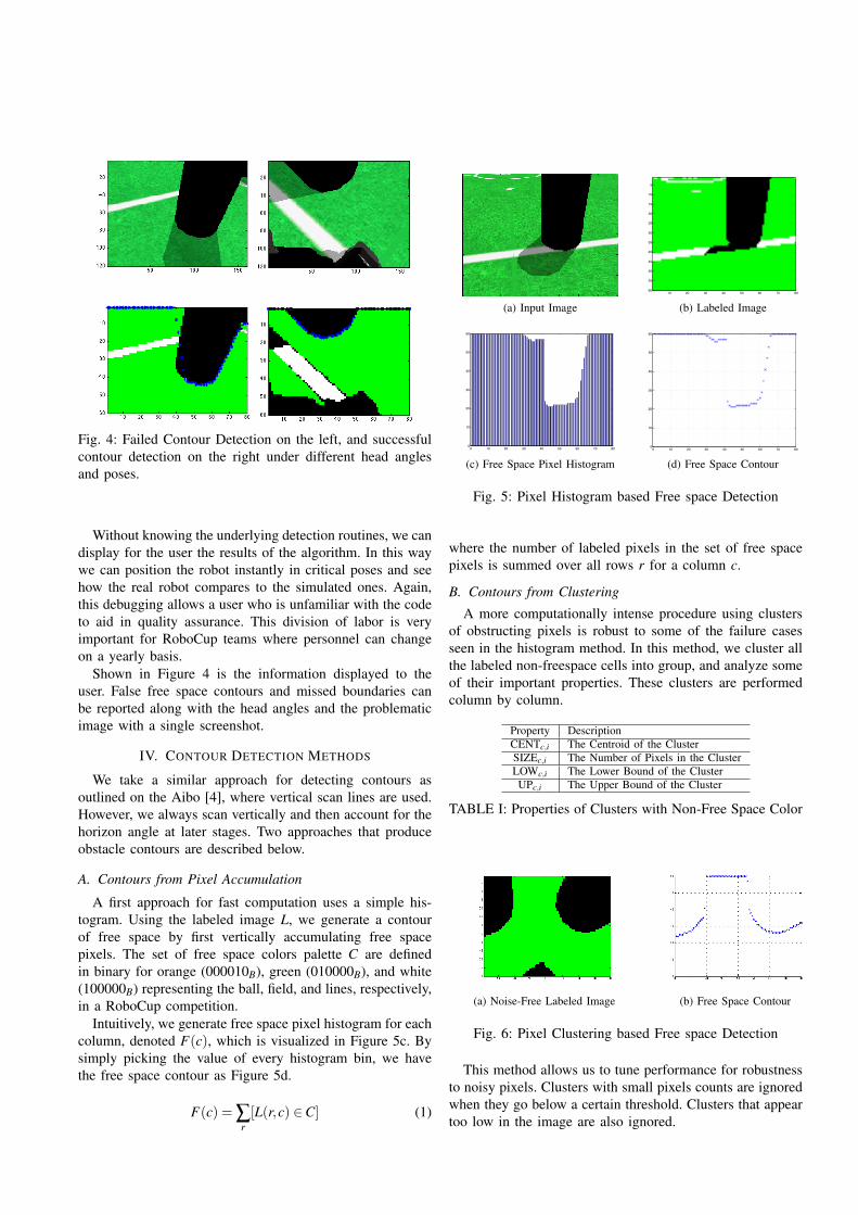
Fig. 4: Failed Contour Detection on the left, and successfulcontour detection on the right under different head anglesand poses.
Without knowing the underlying detection routines, we candisplay for the user the results of the algorithm. In this waywe can position the robot instantly in critical poses and seehow the real robot compares to the simulated ones. Again,this debugging allows a user who is unfamiliar with the codeto aid in quality assurance. This division of labor is veryimportant for RoboCup teams where personnel can changeon a yearly basis.
Shown in Figure 4 is the information displayed to theuser. False free space contours and missed boundaries canbe reported along with the head angles and the problematicimage with a single screenshot.
IV. CONTOUR DETECTION METHODS
We take a similar approach for detecting contours asoutlined on the Aibo [4], where vertical scan lines are used.However, we always scan vertically and then account for thehorizon angle at later stages. Two approaches that produceobstacle contours are described below.
A. Contours from Pixel Accumulation
A first approach for fast computation uses a simple his-togram. Using the labeled image L, we generate a contourof free space by first vertically accumulating free spacepixels. The set of free space colors palette C are definedin binary for orange (000010B), green (010000B), and white(100000B) representing the ball, field, and lines, respectively,in a RoboCup competition.
Intuitively, we generate free space pixel histogram for eachcolumn, denoted F(c), which is visualized in Figure 5c. Bysimply picking the value of every histogram bin, we havethe free space contour as Figure 5d.
F(c) = ∑r[L(r,c) ∈C] (1)
(a) Input Image10 20 30 40 50 60 70 80
5
10
15
20
25
30
35
40
45
50
55
60
(b) Labeled Image
0 10 20 30 40 50 60 70 800
10
20
30
40
50
60
(c) Free Space Pixel Histogram0 10 20 30 40 50 60 70 800
10
20
30
40
50
60
(d) Free Space Contour
Fig. 5: Pixel Histogram based Free space Detection
where the number of labeled pixels in the set of free spacepixels is summed over all rows r for a column c.
B. Contours from Clustering
A more computationally intense procedure using clustersof obstructing pixels is robust to some of the failure casesseen in the histogram method. In this method, we cluster allthe labeled non-freespace cells into group, and analyze someof their important properties. These clusters are performedcolumn by column.
Property DescriptionCENTc,i The Centroid of the ClusterSIZEc,i The Number of Pixels in the ClusterLOWc,i The Lower Bound of the ClusterUPc,i The Upper Bound of the Cluster
TABLE I: Properties of Clusters with Non-Free Space Color
(a) Noise-Free Labeled Image (b) Free Space Contour
Fig. 6: Pixel Clustering based Free space Detection
This method allows us to tune performance for robustnessto noisy pixels. Clusters with small pixels counts are ignoredwhen they go below a certain threshold. Clusters that appeartoo low in the image are also ignored.

V. WORLD COORDINATE PROJECTION
Given any contour producing method, we project theoutput contour into world coordinates for use in avoidancebehaviors. The free space contour CONT(Ix, Iy) is detected inthe image coordinate frame in terms of pixels. We considerthe problem of projecting the pixel based free space contourto robot body coordinate as CONT(xb,yb,zb).
Using a monocular camera mounted on a set of servos, wemust make the assumption that all pixels seen in the frameoccupy the z = 0 plane. We can then project all points tox,y space, and transform those x,y points from the frame ofthe physical camera to the frame of the robot’s foot for apractical frame of reference.
We depict the coordinate transform problem in Figure 7.Our goal is to compute the position P2 in the frame OB whengiven a pixel point P1 with image coordinates (xI ,yI). Wedefine the origin of the camera coordinate frame as P0. Pointsin the camera (non-image) coordinate frame are specifiedas rays P1
b (x1,y1,z1,w), where w can constraint the length.Points in the body coordinate coordinate frame are specifiedas P2
b (x2,y2,z2,1).
P0b = T c
b ×P0
P1b = T c
b ×T Ic P1
(2)
OBXB
YB
ZB
OC
XC
YC
ZC
P2
P1
P0
P3
P4
R
Fig. 7: Projective Transformation Schematic
Consider the ray starting from P0b passing through P1
b . Itintersects the ground plane R at the point P2
b with the relationin Equation 3 where t is chosen such that z2 = 0 for P2
b .
P2b = P0
b − t · (P1b −P0
b ) (3)
We project each point along the free space contour in theimage coordinate frame, CONT(Ix, Iy) using the describedmethod to generate the free space contour CONT(xb,yb) inthe robot’s body frame. This is computationally tractable forthe robot to run at 30fps, since only the boundary pixels areconsidered.
VI. LOCAL CONTOUR TRACKING
For dynamic environments in which the robot also moves,it is important to keep track of the contour as it changes overtime. We initially employed a polar occupancy grid basedon previous work [5] to keep track of the local space of therobot, but decided to switch to a clustering approach for aset of discrete obstacles.
A. Probabilistic Occupancy Grid
We need to account for both odometry and newly per-ceived contours at each timestep. Our approach is to updatethe cartesian occupancy map using log odds ratios, wherenew observations of a grid cell lead to additions, and freespace observations of a cell lead to subtractions. Additionally,for every cell that is not observed, there is a decay of theprobability that that cell is occupied.
The probalistic approach allows for the map to adaptive tochanging environments, since uncertainty in each cell growsover time. This means that our grid is robust to kidnappingof the robot and, potentially, moving obstacles.
An example of this occupancy grid pipeline from imageto occupancy grid is shown in Figure 8.
(a) Global View20 40 60 80 100 120 140 160
20
40
60
80
100
120
(b) YUV Image
10 20 30 40 50 60 70 80
5
10
15
20
25
30
35
40
45
50
55
60
(c) Noise Free Labeled Image−0.5 −0.4 −0.3 −0.2 −0.1 0 0.1 0.2 0.3 0.4 0.5
−0.2
−0.1
0
0.1
0.2
0.3
0.4
0.5
0.6
0.7
0.8
(d) Occupancy Map
Fig. 8: The full pipeline of the occupancy grid systemincluding contour detection.
VII. OBSTACLE AVOIDANCE STRATEGIES
Given the data from the occupancy map, we can generatea host of obstacle avoidance strategies. It is important to beable to rapidly develop and tune these behaviors for optimalperformance in RoboCup. It is very time consuming to dothis with real hardware, as opponents must be operated,and fail cases must be replicated often. We thus wish toevaluate policies in simulation as much as possible. Sinceour vision system can be validated between real hardware

and simulation using the debugging tools described, the nextstep is to validate the behaviors generated.
A. Initial Navigation Strategy
Given an occupancy grid of points, we set up a potentialfield, where the repulsiveness of the field is the summation ofall repulsive effects of the occupied grid cells. The center ofthe goal posts (for our testing strategy) is the lone attractiveforce, with the occupied points providing repulsive forces.
(a) Occupancy Map (b) Occupancy Repulsion
Fig. 9: Modifying the initial trajectory (Dashed arrow) ofthe robot based on a potential field to avoid obstacles (solidarrow)
B. Data Collection
To do this, we compare the paths chosen in identicalscenarios on real hardware and the simulated robot. If thepaths chosen are similar, then we can expect that behaviorsfound in simulation will perform the same on real hardware.The scenario includes 10 cylindrical posts spaced .8 metersapart in the configuration shown in Figure 10. There is a pairof green goalposts on one end of the barrier posts, and therobot on the other end.
We log data on an offboard computer from wirelessdebugging data sent from the robot. We record at 8 Hz thepose of the robot. We show the path points for 3 types ofpaths – starting from the center, starting from the left cornerof the barrier posts, and starting from the right. The testshave been conducted only once to show the working system,however, multiple runs are required for a sound basis ofcomparison.
In Figure 11, the real robot stopped short of the goalposition (3 meters forward, zero meters) in front of theobstacle in front of it. This behavior was observed in thesimulator, where there is a large cluster of blue pose pointsaround the (1,-0.5) mark; however, in the simulator, the roboteventually wandered past the barrier. We would like to runmore trials to capture this behavior where the robot is “stuck”at an impasse, because it shows how the algorithm is notrobust to certain conditions. In other tests, the simulatorbecame stuck but also eventually wandered away, whereasthis case from the left was the one instance where the robotin real life stayed in a stuck position for a prolonged period.
In Figure 12, one difference that we saw was that therobot can choose the left or right at the first obstacle. This
Fig. 10: The configuration of the posts is identical in simu-lation and for real hardware.
Fig. 11: Path comparison between simulation (blue) andreal hardware (red) when starting from the left, where thecoordinates are measured in meters and the goal is (3,0)
makes comparison of the path generation difficult, since eachpath has essentially the same behavior, but there is littleoverlap. One way to remedy this problem is to reduce thesymmetry in the obstacles, as there can be many optimalpaths in environments that are symmetric.
In Figure 13, we find that the reported odometry fromthe real hardware does not match the simulated hardwarein scale. This is to be expected, since there can be more
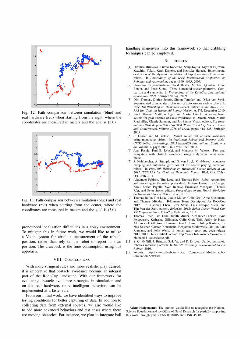
Fig. 12: Path comparison between simulation (blue) andreal hardware (red) when starting from the right, where thecoordinates are measured in meters and the goal is (3,0)
Fig. 13: Path comparison between simulation (blue) and realhardware (red) when starting from the center, where thecoordinates are measured in meters and the goal is (3,0)
pronounced localization difficulties in a noisy environment.To mitigate this in future work, we would like to utilizea Vicon system for absolute measurement of the robot’sposition, rather than rely on the robot to report its ownposition. The drawback is the time consumption using thisapproach.
VIII. CONCLUSIONS
With more stringent rules and more realistic play desired,it is imperative that obstacle avoidance become an integralpart of the RoboCup landscape. With our framework forevaluating obstacle avoidance strategies in simulation andon the real hardware, more intelligent behaviors can beimplemented at a faster rate.
From our initial work, we have identified ways to improvetesting conditions for better capturing of data. In addition tocollecting data from external sources, we also would liketo add more advanced behaviors and test cases where thereare moving obstacles. For instance, we plan to integrate ball
handling maneuvers into this framework so that dribblingtechniques can be employed.
REFERENCES
[1] Hirohisa Hirukawa, Fumio Kanehiro, Shuji Kajita, Kiyoshi Fujiwara,Kazuhito Yokoi, Kenji Kaneko, and Kensuke Harada. Experimentalevaluation of the dynamic simulation of biped walking of humanoidrobots. In Proceedings of the IEEE International Conference onRobotics and Automation, pages 1640–1645, 2003.
[2] Shivaram Kalyanakrishnan, Todd Hester, Michael Quinlan, YinonBentor, and Peter Stone. Three humanoid soccer platforms: Com-parison and synthesis. In Proceedings of the RoboCup InternationalSymposium 2009. Springer Verlag, 2009.
[3] Dirk Thomas, Dorian Scholz, Simon Templer, and Oskar von Stryk.Sophisticated ofine analysis of teams of autonomous mobile robots. InProc. 5th Workshop on Humanoid Soccer Robots at the 2010 IEEE-RAS Int. Conf. on Humanoid Robots, Nashville, TN, December 2010.
[4] Jan Hoffmann, Matthias Jngel, and Martin Ltzsch. A vision basedsystem for goal-directed obstacle avoidance. In Daniele Nardi, MartinRiedmiller, Claude Sammut, and Jos Santos-Victor, editors, 8th Inter-national Workshop on RoboCup 2004 (Robot World Cup Soccer Gamesand Conferences), volume 3276 of LNAI, pages 418–425. Springer,2005.
[5] S. Lenser and M. Veloso. Visual sonar: fast obstacle avoidanceusing monocular vision. In Intelligent Robots and Systems, 2003.(IROS 2003). Proceedings. 2003 IEEE/RSJ International Conferenceon, volume 1, pages 886 – 891 vol.1, oct. 2003.
[6] Juan Fasola, Paul E. Rybski, and Manuela M. Veloso. Fast goalnavigation with obstacle avoidance using a dynamic local visualmodel.
[7] S. Kohlbrecher, A. Stumpf, and O. von Stryk. Grid-based occupancymapping and automatic gaze control for soccer playing humanoidrobots. In Proc. 6th Workshop on Humanoid Soccer Robots at the2011 IEEE-RAS Int. Conf. on Humanoid Robots, Bled, Oct. 26th -Oct. 28th 2011.
[8] Alexander Fabisch, Tim Laue, and Thomas Rfer. Robot recognitionand modeling in the robocup standard platform league. In ChangiuZhou, Enrico Pagello, Sven Behnke, Emanuele Menegatti, ThomasRfer, and Peter Stone, editors, Proceedings of the Fourth Workshopon Humanoid Soccer Robots. o.A., 2010.
[9] Thomas Rofer, Tim Laue, Judith Muller, Colin Graf, Arne Bockmann,and Thomas Munder. B-Human Team Description for RoboCup2012. In Xiaoping Chen, Peter Stone, Luis Enrique Sucar, andTijn Van der Zant, editors, RoboCup 2012: Robot Soccer World CupXV Preproceedings. RoboCup Federation, 2012.
[10] Thomas Rofer, Tim Laue, Judith Muller, Alexander Fabisch, FynnFeldpausch, Katharina Gillmann, Colin Graf, Thijs Jeffry de Haas,Alexander Hartl, Arne Humann, Daniel Honsel, Philipp Kastner, To-bias Kastner, Carsten Konemann, Benjamin Markowsky, Ole Jan LarsRiemann, and Felix Wenk. B-human team report and code release2011, 2011. Only available online: http://www.b-human.de/downloads/bhuman11 coderelease.pdf.
[11] S. G. McGill, J. Brindza, S.-J. Yi, and D. D. Lee. Unified humanoidrobotics software platform. In The 5th Workshop on Humanoid SoccerRobots, 2010.
[12] Webots. http://www.cyberbotics.com. Commercial Mobile RobotSimulation Software.
Acknowledgements: The authors would like to recognize the NationalScience Foundation and the Office of Naval Research for partially supportingthis work through grants CNS 0958406 and ONR 45006.