comparison of two types of dual layer … of two types of dual layer generator in field assisted...
TRANSCRIPT

Progress In Electromagnetics Research B, Vol. 23, 293–309, 2010
COMPARISON OF TWO TYPES OF DUAL LAYERGENERATOR IN FIELD ASSISTED MODE UTILIZING3D-FEM AND EXPERIMENTAL VERIFICATION
E. Afjei and H. Torkaman
Department of Electrical and Computer EngineeringShahid Beheshti University, G.C.Tehran, Iran
Abstract—This paper presents the comparison results between twonew generator configurations. These generator units are namely afield assisted switched reluctance generator (SRG) and a brushless dc(BLDC) generator. No permanent magnets are used in either unit.The field assisted SR generator consists of two magnetically dependentstator and rotor sets (layers), where each stator set includes twelvesalient poles with windings wrapped around them, while the rotorcomprises of eight salient poles without any winding or permanentmagnet. There is a stationary reel, which has the field coil wrappedaround it and is placed between the two-stator sets. The BLDCgenerator is also made up of two magnetically dependent stator androtor sets, but each stator set includes nine salient poles with windingswrapped around them while, the rotor comprises of six salient poleswithout any windings or permanent magnets. There is also a stationaryreel between the two layers to produce the magnetic field through themotor assembly. This magnetic field travels through a guide to therotor then the stator and finally completes its path via the generatorhousing. The generator phase windings for each layer are connect suchthat all the stator poles in that set can have either north or southpole configuration while the stator poles in the other layer have theopposite pole arrangement. This type of connection can be used inmotoring mode as well. To evaluate the performance of the generators,two types of analysis, namely, numerical technique and experimentalstudy have been utilized. In the numerical analysis, three dimensionalfinite element analysis is employed, whereas in the experimental study,proto-types have been built and tested.
Received 8 June 2010, Accepted 19 July 2010, Scheduled 25 July 2010Corresponding author: H. Torkaman (h [email protected]).

294 Afjei and Torkaman
1. INTRODUCTION
Nowadays, various parameters such as variable load flexibility, highreliability, low investment cost and maintenance, small transmissionloss leads to have more attention in the area of distributed powergeneration systems. As a result of several researches to achieve thispurpose, well-developed technologies in the area of reluctance andbrushless dc generators have now evolved. Whereas, both generatortypes offer a number of advantages and supply proportionate toapplications demands [1, 2].
Moreover, with the quick and wide development of the controltechnologies and power electronic instruments, the brushless electricmachines are replacing with the brush electric machines, and alsomechanical switches are replaced with much faster and more reliablesolid state electronic switches [3–5]. Consequently, the switchedreluctance and brushless dc generators have been developed for variousshapes and sizes in different power ratings and used in industry [6, 7].
The reluctance machine has begun to realize its potential inthe new era of power electronics and computer-aided electromagneticdesign. The machine development has matured to the pointthat its impact is now evident in the industry. The typesof reluctance machines available in the marketplace today areprimarily of the regular cylindrical geometry although the disc andmulti layer geometries have been proposed in limited use [8, 9].SR Generator (SRG) is also an attractive solution for worldwideincreasing demands for electrical energy. It is low cost, faulttolerant with a rugged structure and operates with high efficiencyover a wide speed range. The SRG have been utilized for someapplications like starter/generator for gas turbine of aircrafts [10, 11]wind power generator [12, 13] and as an alternator for automotiveapplications [14, 15]. These machines provide several advantagesincluding simplicity in construction, cooling, geometric versatility,durability, and higher permissible rotor temperature.
The BLDC machines have gained popularity due to thedevelopment of high flux density and reliable and permanent magnets.BLDCMs are used in industries for different applications suchas, automotive, aerospace, home appliances, and many industrialequipment and instrumentation [16, 17]. The construction of modernBLDC machines is very similar to the ac machine, known as thepermanent magnet synchronous machine. Out of these, 3-phasemachines are the most popular and widely used. The stator of aBLDCM consists of stacked steel laminations with windings placedin the slots that are axially cut along the inner periphery or around

Progress In Electromagnetics Research B, Vol. 23, 2010 295
stator salient poles. The rotor is made of permanent magnet and canvary from two to eight pole pairs with alternate north (N) and south(S) poles.
The standard BLDC generator lacks field control due to use ofpermanent magnet in the rotor assembly. The output voltage can becontrolled by either variation in generator speed or use of some kind ofdrive circuit to hold the output voltage at a desirable level for differentspeeds. A standard SRG can only produce power during the decreasingphase inductance profile which limits its output power production.
The new generators use a field assisted scheme to produce themagnetic flux through the machine assembly. It also does not use anykinds of brushes for the stationary field coil placed between the twostator sets. The current flows into the coil by simply connecting thefield terminals to a dc voltage source, and it can be controlled easily toproduce the desired output voltage at almost any speed. The currentthrough the field can be reduced to zero in case of any malfunctioningof the drive circuit in order to protect the generator load from highvoltage production at high speeds.
In this paper, the comparison results of a new brushlessDC generator, with a switched reluctance generator in their newconfigurations have been studied. These generators are goodcandidates for hybrid vehicles applications and wind energy conversionsystems in low voltage applications. The proposed generators areconstructed with two layers and a field assisted unit. The design andoptimization of the machines for comparative study was performedwith the aid of a three dimensional finite element magnetic fieldpackage.
This paper is organized as follows: Section 2 briefly explains thedouble layer machines design and calculated geometrical parametersin both of them. The three dimensional finite element results ofthe generators electromagnetic profiles are obtained and compared inSection 3. Section 4 contains the discussion about generated voltagein machines and Section 5 includes the physical assembly of thetwo machines as well as the experimental results obtained from thenew dual layer switched reluctance and brushless dc generators, andfollowed by conclusions in Section 6.
2. THE DESIGN FEATURES OF PROPOSED DUALLAYER MACHINES
In design procedure of the generators, for achieving maximum outputvoltage as well as power for a certain machine volume, a newconstruction in their geometries are considered. The generator

296 Afjei and Torkaman
configurations for brushless dc and switched reluctance units aremodified and designed based on having double layers of the stator/rotorand a stationary field assisted coil placed between them. Thesemodifications caused significant improvements in both generator unitswhich makes them distinct from other types of generators. Theseconfigurations consist of two layers and a field coil which produceSouth Pole in one layer and the North Pole in the other layer. Inaddition, due to existence of a field assisted coil between the two layersan independent field is produced in the generator units, which canproduce higher output power than a standard self excited generator.The design details are briefly explained below.
2.1. Dual Layer dc Generatr (DLDCG)
The brushless generator consists of two magnetically dependent statorand rotor layers (sets), where each stator set includes nine salient poleswith windings wrapped around them while, the rotor comprises of sixsalient poles. Every stator and rotor pole arc is about 30. The twolayers are exactly symmetrical with respect to a plane perpendicularto the middle of the generator shaft. This is a three phase generator,therefore, three coil windings from one layer is connected in series withthe other three coil windings in the other layer. These coils togethermake one of the generator phases.
There is a stationary reel, which has the field coils wrapped aroundit and is placed between the two-stator sets. This reel has a rotatingcylindrical core, which guides the magnetic field. The magnetic fluxproduced by the coils travels through the guide and the shaft to therotor and then to the stator poles, and finally closes itself throughthe generator housing. Therefore, one set of the rotor poles hasmagnetically North Pole while the other set is magnetically South Poleconfiguration. In this generator, the magnetic field has been inducedto the rotor without using any brushes to inject the current into thefield winding.
In order to get a better view of the generator configurations, thecomplete generator assembly without coils winding is shown in Fig. 1.
The proposed DLDC generator dimensions are listed in Table 1.
2.2. Dual Layer Switched Reluctance Generator (DLSRG)
The switched reluctance generator consists of two magneticallydependent stator and rotor layers, where each stator set includes twelvesalient poles with windings wrapped around them while, the rotorcomprises of eight salient poles. Every stator and rotor pole arcs are14 and 16, respectively. The two layers are exactly symmetrical with

Progress In Electromagnetics Research B, Vol. 23, 2010 297
(a)
(b)
2nd layer of stator
Machine housing
1st layer of stator
1st layer of rotor
2nd layer of rotor
Field core
Figure 1. The DLDC generator; (a) different parts, (b) completeassembly (without coil windings).
Table 1. DLDC generator dimensions.
Parameter ValueStator core outer diameter 78 mmStator core inner diameter 68 mmRotor core outer diameter 35.5 mm
Length of air gap 0.25mmShaft diameter 15mmRotor pole arc 30
Stator pole arc 30
Number of turns per stator pole 120Number of turns in assistant field 300
respect to a plane perpendicular to the middle of the generator shaft.This is a three phase generator, therefore, four coil windings from onelayer is connected in series with the other four coil windings in the otherlayer. The coil windings in each layer are such that the stator poles gaineither North or South Pole configuration for the generator mode. Inthe machine operation each layer can operate independently, in seriesor parallel with each other. In another words, each layer consist of atwelve by eight cylindrical switched reluctance generator configurationsharing common shaft and can be connected to each other in threepossible ways. There is a stationary reel, which has the field coilswrapped around it and is placed between the two-stator sets. This reelhas a rotating cylindrical core, which guides the magnetic field. Themagnetic flux produced by the coils travels through the guide and the

298 Afjei and Torkaman
generator shaft to the rotor and then to the stator poles, and finallycloses itself through the generator housing. Therefore, one set of rotorpoles is magnetically north and the other set is magnetically south. Inthis generator, the magnetic field has been induced in the rotor withoutusing any brushes to inject current in to the field winding.
For a better illustration of the proposed generator configurations,the complete assembly without coils winding is presented in Fig. 2.
The DLSR generator specifications calculated for the study isshown in Table 2.
It must be pointed out that the machines have different diametersbut they have the same volume and the same amount of iron instators and rotors are used. This is note worthy to mention thatthese generators can operate in two modes of operation namely; filed
(a)
(b)
2nd layer of stator
Machine housing
1st layer of stator
1st layer of rotor
2nd layer of rotor
Field core
Figure 2. The DLSR generator; (a) different parts, (b) completeassembly (without coil windings).
Table 2. DLSR generator dimensions.
Parameter ValueStator core outer diameter 72 mmStator core inner diameter 62 mmRotor core outer diameter 41.5 mm
Length of air gap 0.25mmShaft diameter 15mmRotor pole arc 16
Stator pole arc 14
Number of turns per stator pole 100Number of turns in assistant field 300

Progress In Electromagnetics Research B, Vol. 23, 2010 299
assisted mode and self excited mode. In this study field assisted modeis considered for the comparative study in this paper. Two types ofanalysis namely numerical and experimental have been performed.
3. COMPARISON OF ELECTROMAGNETICPROPERTIES
To properly evaluate the generator design and performance, a reliablemodel is required [18–20]. Finite element analysis (FEA) is beingused to determine the magnetic field distribution in and around thegenerator [21, 22]. In order to present the operation of the generatorand to determine the main profiles and parameters at differentpositions of the rotor, the field solutions are obtained. The threedimensional field analysis has been performed using a Magnet CADpackage [23] to consider the end effects and axial fringing fields effectfor simulating reliable model which is based on the T -Ω technique.
In the finite element analysis, second order triangular elementswith dense meshes at places where the variation of fields are greaterhave been used.
In this analysis, the usual assumptions such as the magnetic fieldoutside of an air box in which the generator is placed, is consideredto be zero. The comparison results for 9/6 DLDCG and 12/8 DLSRGincluding magnetic flux density, flux-linkages, terminal inductance perphase, mutual inductances and produced voltage for various excitationin one complete rotor rotation are obtained and discussed below.
3.1. Magnetic Flux Density
The design of the generator becomes complicated due to complexgeometry and material saturation. Moreover an accurate knowledgeof the flux distribution inside the generator for different excitationcurrents and rotor positions are essential for the prediction of generatorperformance. These generators can be highly saturated under normaloperating conditions. Fig. 3 shows the magnetic flux density arrowsfor fully-aligned case when the generators operates in the field assistedmode, which produce north pole in one layer and south pole in theopposite layer. Hence for proper operation of the generator, thetwo layers should be working simultaneously. The field current isconsidered to be at 0.5 A for this study.
As shown in Fig. 3, the majority of flux distribution isconcentrated in aligned stator and corresponding rotor poles. Theamplitude of magnetic flux densities in aligned stator poles is 0.95 and

300 Afjei and Torkaman
1.42 Tesla for DLDCG and DLSRG, respectively. These values showthe DLSR generator operates in nonlinear or saturation region.
(a) (b)
Figure 3. The magnetic flux density for fully-aligned cases in: (a)DLDCG, (b) DLSRG.
(a)(b)
(c)
Figure 4. The magnetic flux density for half-aligned cases in DLDCG:(a) without stators and housing, (b) without housing, (c) completeassembly.

Progress In Electromagnetics Research B, Vol. 23, 2010 301
The plots of magnetic flux density for the generators in half-aligned case for different generators parts are shown in Fig. 4 andFig. 5.
Figures 4 and 5 show the aligned corner of rotor and stator polesare in saturation and maximum magnetic flux density is about 1.02Tesla in reluctance generator. Also, the maximum magnetic fluxdensity in dc generator is about 0.95 Tesla at some small local points onthe very tip of the stator pole. For assessing the generators operation,the assisted field is excited under different current amplitudes (If ) inboth of machines. Maximum flux density in stator pole for variouscurrent excitations in fully alignment (Bfa) and half alignment (Bha)positions are listed in Table 3.
(a) (b)
(c)
Figure 5. The magnetic flux density for half-aligned cases in DLSRG:(a) without stators and housing, (b) without housing, (c) completeassembly.
Table 3. Maximum flux density in stator pole.
Machine Type DLDCG DLSRGIf (A) 0.25 0.5 0.75 0.25 0.5 0.75
Bfa (T) 0.40 0.79 0.99 0.71 1.02 1.09Bha (T) 0.56 0.95 1.18 1.07 1.42 1.50

302 Afjei and Torkaman
As depicted in Table 3, with an increase in field current theamplitude of flux densities in fully and half alignment rotor positionsare increased in both generators. On the other side, the flux densityof DLSRG in fully alignment has 43%, 22% and 9% higher amplitudethan DLDCG under 0.25, 0.5 and 0.75A field current, respectively. Inaddition, these values go up to 47%, 33% and 21% when the machineis in half alignment rotor position which causes more magnetic forcebetween rotor and stator poles. The differences between flux densitiesin both machines are due to their geometries in terms of the numberof stator and rotor poles. Since the numbers of poles in fully alignedposition as well as the amount of overlapping in SR generator are morethan the dc generator, then the flux magnitude is higher in SRG. Inother words, complete aligned position in dc generator accompaniedby more mutual flux due to stator poles configuration compared to SRgenerator. From another point of view, the higher flux amplitude ofreluctance generator can be disadvantageous when the asymmetricallydisturbance occurs because that leads the generator to face with morenoise and vibration.
3.2. Flux Linkage and Inductance
In this study, the analysis includes a 360 degree rotation of the rotor toanalyze the generators behaviors at the different rotor positions. Dueto symmetrical shape of the stator/rotor assembly, the rotor movementfrom fully aligned to unaligned position is considered (phase A) forevaluating the performance of the generators. Fig. 6 shows the fluxlinkage for phase A in DLDCG that includes 6 series coils from twostator assembly.
Figure 7 illustrates the flux linkage from phase A in DLSRG whichincludes 8 series coils from two stator layers. The mutual inductancehas been defined as the ratio of each phase flux linkage to the excitingcurrent of the assisted field (Eq. (9)). Therefore, the variation ofmutual inductance is proportional to variation of flux linkage whenthe current is considered to be constant.
L = λ(θ)/If (1)
As shown in Fig. 6 and Fig. 7, the amplitude of flux linkage as wellas the phase inductance will go up in both machines with raising thefield current. As shown in these figures, the maximum amplitude ofterminal inductance in DLSR generator is 1.9, 1.6 and 1.3 times higherthan those of inductance amplitude in DLDC generator, with 0.25, 0.5and 0.75 A of field current, respectively.

Progress In Electromagnetics Research B, Vol. 23, 2010 303
0
0.01
0.02
0.03
0.04
0.05
0.06
0.07
0.08
0 4 8 12 16 20 24 28 32
Flu
xL
ink
ag
e_A
(W
b)
(DL
DC
G)
I=0.75A
I=0.5A
I=0.25A
Rotor Position (Deg)
Figure 6. The flux linkage forphase A in DLDCG.
0
0.01
0.02
0.03
0.04
0.05
0.06
0.07
0.08
0.09
0.1
0 4 8 12 16 20
Flu
xL
ink
ag
e_A
(W
b)
(DL
SR
G)
I=0.75A
I=0.5A
I=0.25A
Rotor Position (Deg)
Figure 7. The flux linkage forphase A in DLSRG.
4. COMPARISON OF VOLTAGE PRODUCTION
As seen from Fig. 1 and Fig. 2, the DLDCG has nine stator poles as wellas six rotor poles, while DLSRG has twelve stator poles as well as eightrotor poles which will be engaged in the voltage production mechanism.In this analysis the produced voltages in proposed generators areobtained based on Faraday’s law of induction (Eq. (2)) which explainsthat the induced voltage (V ), in the generator depends on the numberof turns (N) and the time derivative of magnetic flux. It is expressedas follow,
V = −Ndϕ
dt= −N
dϕ
dθ· dθ
dt= −N
dϕ
dθω (2)
In order to estimate the shape of the generated voltage, the obtainedsimulated flux linkage data are estimated by a fourth order equation.The voltage produced in each coil is computed using Eq. (2). Coils1,2,3 from 1st layer, and coils 4,5,6 from 2nd layer are in series andthey are belong to phase A then, the equivalent voltage is calculatedfrom summing the produced voltage in each individual coil for DLDCG.The same procedure is applied for DLSRG, coils 1,2,3,4 from 1st layer,and coils 5,6,7,8 from 2nd layer are in series and they belong to phaseA.
The terminal voltage belonging to phase A under different loadsare calculated in appropriate switching cycle and presented in Fig. 8and Fig. 9 for dc and reluctance generators, respectively.
In these figures, the produced voltages in negative and positiveperiod are clearly shown. It is worth mentioning here that, the statorand rotor cores are made of a non-oriented silicon steel lamination.The magnetization curve is taken from manufacturer’s data sheet forM-27 steel.

304 Afjei and Torkaman
-4
-3
-2
-1
0
1
2
3
4
0.00 0.14 0.28 0.42 0.59 0.73 0.87 1.01 1.15
Vo
ltag
e_A
(v
) (D
LD
CG
)
I=0.75A
I=0.5A
I=0.25A
Rotor Position (rad)
Figure 8. The terminal voltagefor phase A in DLDCG.
-10
-8
-6
-4
-2
0
2
4
6
8
10
0.00 0.07 0.14 0.21 0.28 0.35 0.42 0.52 0.59 0.66
Vo
ltag
e_A
(v
) (D
LS
RG
)
I=0.75A
I=0.5A
I=0.25A
Rotor Position (rad)
Figure 9. The terminal voltagefor phase A in DLSRG.
As seen from Fig. 8 the maximum amplitude of generated voltagein DLDCG is 1.25, 2.5 and 3.5 volt under field currents of 0.25, 0.5and 0.75 (A), respectively. On the other side, it is shown that, themagnitude of produced voltage in phase A has 2 and 3 times highervalue when the field current has increased by factors of 2 and 3. Itmeans the percentage of increasing output voltage is proportional topercentage variation of filed current (Eq. (3)).
∆V = ∆If (3)
Figure 9 shows the generated voltage waveform in DLSR generatorthat has its maximum value at 4.5, 7.3 and 8.1 volts under differentmentioned field currents, respectively. The test condition for thismachine is similar to the dc generator. Moreover, it is observed thatthe amount of produced voltage in phase A has 1.63 and 1.8 timeshigher values when the field current has increased by factors of 2 and3. On other hands, the percentage of increasing in output voltage isnot proportional to percentage variation of filed current such as the dcmachine. It has linear relation that can be expressed in the form of:
∆V = 0.1739∆If + 1.2869 (4)
Consequently, it can be concluded that the achieved terminal voltagein reluctance generator is higher than that of the dc generator underdifferent loadings for the same conditions.
One of the major factors in obtaining different generated voltagebetween the two generator models is due to the different number ofpoles participating in voltage production. In SR generator eight polesand in DC generator six poles are joined to produce output voltage inone phase.
Progress In Electromagnetics Research B, Vol. 23, 2010 305
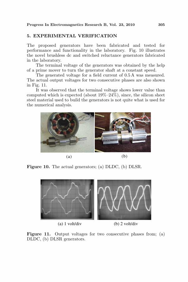
5. EXPERIMENTAL VERIFICATION
The proposed generators have been fabricated and tested forperformance and functionality in the laboratory. Fig. 10 illustratesthe novel brushless dc and switched reluctance generators fabricatedin the laboratory.
The terminal voltage of the generators was obtained by the helpof a prime mover to turn the generator shaft at a constant speed.
The generated voltage for a field current of 0.5 A was measured.The actual output voltages for two consecutive phases are also shownin Fig. 11.
It was observed that the terminal voltage shows lower value thancomputed which is expected (about 19%–24%), since, the silicon sheetsteel material used to build the generators is not quite what is used forthe numerical analysis.
(a) (b)
Figure 10. The actual generators; (a) DLDC, (b) DLSR.
(a) 1 volt/div (b) 2 volt/div
Figure 11. Output voltages for two consecutive phases from; (a)DLDC, (b) DLSR generators.

306 Afjei and Torkaman
0
5
10
15
20
25
0.2 0 .5 1.1 2 .3 2.7 3 .7 7 14
Vo
ltag
e (v
) (D
LD
CG
)
I=0.75A
I=0.5A
I=0.25A
I=1A
(a)
0
2
4
6
8
10
12
14
16
18
20
0.5 1 2 4 6 12
Vo
ltag
e (v
) (D
LS
RG
)
I=2A
I=1A
(b)
Power (p) Power (p)
Figure 12. Output voltage vs. power (2500 rpm) from; (a) DLDC,(b) DLSR generators.
Figure 11(a) clearly shows the harmonics in dc generator outputvoltage which is due to slot harmonics as well as saturation in therotor/stator poles. Fig. 11(b) depicts saturation in the SRG outputvoltage.
The speed of the motor is kept at 2500 rpm under different loadsfor various field currents. The output power versus the rectifiedoutput voltage is measured. The results of these tests are shown inFigs. 12(a), (b) for DLDC and DLSR generators respectively. Thepower curve fitting has been used for the data points.
6. CONCLUSION
In this paper, two new generator units were tested numerically andexperimentally and then some of the generator parameters are obtainedand compared. The experimental output voltage for SRG shows clearlythe effect of saturation on the waveform which has a high content ofthird harmonics while the Brushless dc shows more tooth harmonicsdue to variation of the airgap. The average power obtained from thebrushless dc generator for the same amount of field current magnitudeis 10% higher than that of SRG. Comparing the plots of output voltagewaveforms developed by the generator units, it can be seen that theDLDCG show about 50% higher voltages (in maximum value) thanSRG. Since no permanent magnet is used in either of the generatorunits then they are very rugged and durable and have the potential tobe used in very harsh environments. The output voltage magnitudesfrom the generator units are easily controlled by controlling the fieldcurrent. The comparative study on the above two machines shows the

Progress In Electromagnetics Research B, Vol. 23, 2010 307
DLSR machine has better electromagnetic property and the DLDCmachine has better mechanical behavior.
ACKNOWLEDGMENT
This work was supported by vice-presidency of research and technologyof Shahid Beheshti University.
REFERENCES
1. Schofield, N. and S. Long, “Generator operation of a switchedreluctance starter/generator at extended speeds,” IEEE Transac-tions on Vehicular Technology, Vol. 58, No. 1, 48–56, 2009.
2. Lee, H., et al., “Practical control for improving power density andefficiency of the BLDC generator,” IEEE Transactions on PowerElectronics, Vol. 20, No. 1, 192–199, 2005.
3. Lee, H. W., T. H. Kim, and M. Ehsani, “Maximum powerthroughput in the multiphase brushless DC generator,” IEEProceedings Electric Power Applications, Vol. 152, No. 3, 501–508,2005.
4. Kim, T., H. W. Lee, and M. Ehsani, “Position sensorless brushlessDC motor/generator drives: Review and future trends,” IETElectric Power Applications, Vol. 1, No. 4, 557–564, 2007.
5. Chen, H. C., T. Y. Tsai, and C. K. Huang, “Low-speed performance comparisons of back-EMF detection circuitswith position-dependent load torque,” IET Electric PowerApplications, Vol. 3, No. 2, 160–169, 2009.
6. Zhang, Z., Y. Yan, S. Yang, et al., “Development of a newpermanent-magnet BLDC generator using 12-phase half-waverectifier,” IEEE Transactions on Industrial Electronics, Vol. 56,No. 6, 2023–2029, 2009.
7. Chen, H. and J. J. Gu, “Implementation of the three-phaseswitched reluctance machine system for motors and generators,”IEEE Transactions on Mechatronics, Vol. 15, No. 3, 421–432,2010.
8. Torkaman, H. and E. Afjei, “FEM analysis of angularmisalignment fault in SRM magnetostatic characteristics,”Progress In Electromagnetics Research, Vol. 104, 31–48, 2010.
9. Afjei, E., A. Seyadatan, and H. Torkaman, “A new two phasebidirectional hybrid switched reluctance motor/field-assistedgenerator,” Journal of Applied Sciences, Vol. 9, No. 4, 765–770,2009.

308 Afjei and Torkaman
10. Ding, W. and D. Liang, “Dynamic modeling and control fora switched reluctance starter/generator system,” InternationalConference on Electrical Machines and Systems, 3315–3320, 2008.
11. Ferreira, C. A., S. R. Jones, W. S. Heglund, et al., “Detailed designof a 30-kW switched reluctance starter/generator system for agas turbine engine application,” IEEE Transactions on IndustryApplications, Vol. 31, No. 3, 553–561, 1995.
12. Echenique, E., J. Dixon, R. Cardenas, et al., “Sensorless controlfor a switched reluctance wind generator, based on currentslopes and neural networks,” IEEE Transaction on IndustrialElectronics, Vol. 56, No. 3, 817–825, 2009.
13. Cardenas, R., R. Pena, M. Perez, et al., “Control of a switchedreluctance generator for variable-speed wind energy applications,”IEEE Transaction on Energy Conversion, Vol. 20, No. 4, 781–791,2005.
14. Fahimi, B., A. Emadi, and R. B. Sepe, Jr., “A switched reluctancemachine-based starter/alternator for more electric cars,” IEEETransactions on Energy Conversion, Vol. 19, No. 1, 116–124, 2004.
15. Afjei, E. and H. Torkaman, “The novel two phase field-assisted hybrid SRG: Magnetio static field analysis, simulation,and experimental confirmation,” Progress In ElectromagneticsResearch B, Vol. 18, 25–42, 2009.
16. Hanselman, D. C., Brushless Permanent Magnet Motor Design,McGraw-Hill, New York, 1994.
17. Afjei, E. and H. Toliyat, “A novel hybrid brushless dcmotor/generator for hybrid vehicles applications,” InternationalConference on Power Electronics, Drives and Energy Systems, 1–6, 2006.
18. Ravaud, R., G. Lemarquand, V. Lemarquand, and C. Depollier,“The three exact components of the magnetic field createdby a radially magnetized tile permanent magnet,” Progress InElectromagnetics Research, Vol. 88, 307–319, 2008.
19. Ravaud, R., G. Lemarquand, V. Lemarquand, S. I. Babic, andC. Akyel, “Mutual inductance and force exerted between thickcoils,” Progress In Electromagnetics Research, Vol. 102, 367–380,2010.
20. Ravaud, R., G. Lemarquand, V. Lemarquand, S. Babic, andC. Akyel, “Mutual inductance and force exerted between thickcoils,” Progress In Electromagnetics Research, Vol. 102, 367–380,2010.
21. Torkaman, H. and E. Afjei, “Magnetio static field analysis

Progress In Electromagnetics Research B, Vol. 23, 2010 309
regarding the effects of dynamic eccentricity in switched reluctancemotor,” Progress In Electromagnetics Research M, Vol. 8, 163–180,2009.
22. Torkaman, H. and E. Afjei, “Hybrid method of obtaining degreesof freedom for radial airgap length in SRM under normal andfaulty conditions based on magnetiostatic model,” Progress InElectromagnetics Research, Vol. 100, 37–54, 2010.
23. Magnet CAD package, User Manual, Infolytica Corporation Ltd.,2007.